

Page 1
Page 2

Page 3

SINAMICS
SINAMICS DCP
Operating Instructions
05/2016
A5E34382853K
Preface
Introduction
1
Safety notes
2
Description
3
Preparations for use
4
Mounting
5
Electrical connection
6
Commissioning
7
Operation
8
Servicing
9
Spare parts
10
Disposal
11
Service and Support
A
Technical data
B
Quality documents
C
Additional documents
D
Checklists and forms
E
Assembly documents
F
Index
G
Page 4

Siemens AG
Division Process Industries and Drives
Postfach 48 48
90026 NÜRNBERG
GERMANY
Document order number: A5E34382853K
Ⓟ
Copyright © Siemens AG 2014 - 2016.
All rights reserved
Legal information
Warning notice system
DANGER
indicates that death or severe personal injury will result if proper precautions are not taken.
WARNING
may
CAUTION
indicates that minor personal injury can result if proper precautions are not taken.
NOTICE
indicates that property damage can result if proper precautions are not taken.
Qualified Personnel
personnel qualified
Proper use of Siemens products
WARNING
Siemens products may only be used for the applications described in the catalog and in the relevant technical
maintenance are required to ensure that the products operate safely and without any problems. The permissible
ambient conditions must be complied with. The information in the relevant documentation must be observed.
Trademarks
Disclaimer of Liability
This manual contains notices you have to observe in order to ensure your personal safety, as well as to prevent
damage to property. The notices referring to your personal safety are highlighted in the manual by a safety alert
symbol, notices referring only to property damage have no safety alert symbol. These notices shown below are
graded according to the degree of danger.
indicates that death or severe personal injury
If more than one degree of danger is present, the warning notice representing the highest degree of danger will
be used. A notice warning of injury to persons with a safety alert symbol may also include a warning relating to
property damage.
result if proper precautions are not taken.
The product/system described in this documentation may be operated only by
task in accordance with the relevant documentation, in particular its warning notices and safety instructions.
Qualified personnel are those who, based on their training and experience, are capable of identifying risks and
avoiding potential hazards when working with these products/systems.
Note the following:
documentation. If products and components from other manufacturers are used, these must be recommended
or approved by Siemens. Proper transport, storage, installation, assembly, commissioning, operation and
All names identified by ® are registered trademarks of Siemens AG. The remaining trademarks in this publication
may be trademarks whose use by third parties for their own purposes could violate the rights of the owner.
We have reviewed the contents of this publication to ensure consistency with the hardware and software
described. Since variance cannot be precluded entirely, we cannot guarantee full consistency. However, the
information in this publication is reviewed regularly and any necessary corrections are included in subsequent
editions.
for the specific
05/2016 Subject to change
Page 5

Preface
Device software version
Older software versions
Newer software versions
SINAMICS DCP documentation available
SINAMICS DCP Operating Instructions
Contains all information on
ordering, installation, connecting, commissioning, maintaining, description of functions,
and service
SINAMICS DCP List Manual
Contains
parameter list, function diagrams, list of faults and alarms
SINAMICS Free Function Blocks, Commissioning Manual
Contains a general description, the list of parameters, the function diagrams as well as
the list of faults and alarms.
SINAMICS DCP DVD Documentation
Contains, among others:
•
•
When these Operating Instructions went to print, SINAMICS DCP units were being supplied
from the factory with the software release specified on Page 3. However, these Operating
Instructions can, in principle, also apply to other software versions.
●
It is possible that not all of the functions described here may be available.
●
It is possible that the SINAMICS DCP may feature additional functions that are not
described in these Operating Instructions. Do not change any parameters that you cannot
find in the List Manual from their factory setting, and do not give parameters any values
that are not specified in the List Manual.
The software release is displayed using r50060[6].
Example:
01010203 displayed on the BOP20 means 01.01.02.03 → Version 1.1, Service Pack 2,
Hotfix 3
Downloading the latest software version
(https://support.industry.siemens.com/cs/ww/en/view/109474935
All the manuals mentioned above in all the available languages
The function diagrams in VISIO format
)
SINAMICS DCP
Operating Instructions, 05/2016, A5E34382853K
5
Page 6

Preface
Manuals in the Internet
Further Internet links
The manuals are also available in the Internet:
Manuals (https://support.industry.siemens.com/cs/ww/en/ps/13302
The list of general conditions available there include current supplements to the manuals.
The notes included in the general condition lists have a higher priority than the statements
made in the manuals.
)
Generic station description file (GSD) for
PROFIBUS (https://support.industry.siemens.com/cs/ww/en/view/98206128
PROFINET (https://support.industry.siemens.com/cs/at/en/view/98207877)
)
SINAMICS DCP
6 Operating Instructions, 05/2016, A5E34382853K
Page 7

Table of contents
Preface ................................................................................................................................................... 5
1 Introduction ........................................................................................................................................... 13
2 Safety notes .......................................................................................................................................... 15
3 Description ............................................................................................................................................ 23
4 Preparations for use .............................................................................................................................. 25
5 Mounting ............................................................................................................................................... 31
6 Electrical connection ............................................................................................................................. 35
7 Commissioning ..................................................................................................................................... 71
2.1 Safety concept ........................................................................................................................ 17
2.2 Notes on operator protection .................................................................................................. 18
2.2.1 Information about electromagnetic fields ................................................................................ 20
2.3 Notes on plant safety .............................................................................................................. 21
2.4 ESD-sensitive components ..................................................................................................... 22
4.1 Device order numbers............................................................................................................. 25
4.2 Rating plate ............................................................................................................................. 26
4.3 Ordering information for options and accessories .................................................................. 28
6.1 EMC-compliant installation ..................................................................................................... 36
6.1.1 Basic information about EMC ................................................................................................. 36
6.1.2 EMC-compliant installation of SINAMICS DCP (installation instructions) .............................. 38
6.2 Block diagram with connection suggestion ............................................................................. 40
6.3 Components ............................................................................................................................ 43
6.4 Terminals and connectors ...................................................................................................... 45
6.5 Additional system components ............................................................................................... 57
6.5.1 Option Board: Communication Board EtherNet CBE20 ......................................................... 57
6.5.1.1 Description .............................................................................................................................. 57
6.5.1.2 Safety instructions ................................................................................................................... 57
6.5.1.3 Interface description ................................................................................................................ 58
6.5.1.4 Meaning of the LEDs .............................................................................................................. 59
6.5.1.5 Assembling the 30 kW device ................................................................................................. 62
6.5.1.6 Assembling the 120 kW device ............................................................................................... 64
6.5.1.7 Technical data ......................................................................................................................... 65
6.5.2 Terminal Module Cabinet TMC (option G63) .......................................................................... 65
7.1 Switching on ............................................................................................................................ 73
7.1.1 BOP20 status display during ramp-up .................................................................................... 73
SINAMICS DCP
Operating Instructions, 05/2016, A5E34382853K
7
Page 8

Table of contents
8 Operation ............................................................................................................................................. 107
7.2 Commissioning using the BOP20 operator panel .................................................................. 75
7.2.1 Requirements ......................................................................................................................... 75
7.2.2 Commissioning steps ............................................................................................................. 75
7.3 Commissioning with the STARTER commissioning tool ....................................................... 78
7.3.1 STARTER commissioning tool ............................................................................................... 78
7.3.1.1 Description ............................................................................................................................. 78
7.3.1.2 Installing the STARTER commissioning tool ......................................................................... 78
7.3.1.3 Layout of the STARTER user interface ................................................................................. 79
7.3.2 Procedure for commissioning with STARTER ....................................................................... 79
7.3.2.1 Basic procedure when using STARTER ................................................................................ 79
7.3.2.2 Creating the project ................................................................................................................ 80
7.3.2.3 The STARTER project wizard ................................................................................................ 81
7.3.2.4 Configuring a drive unit .......................................................................................................... 88
7.3.2.5 Starting the drive project ........................................................................................................ 95
7.3.2.6 Connection through a serial interface .................................................................................... 99
7.4 Activating function modules ................................................................................................. 102
7.4.1 Activating offline via STARTER ........................................................................................... 102
7.4.2 Activating online via parameters
.......................................................................................... 103
8.1 Operation ............................................................................................................................. 107
8.1.1 Basics ................................................................................................................................... 107
8.1.1.1 Parameters ........................................................................................................................... 107
8.1.1.2 Data sets .............................................................................................................................. 110
8.1.1.3 Drive objects ........................................................................................................................ 111
8.1.1.4 Memory card functions ......................................................................................................... 113
8.1.1.5 BICO technology: Interconnecting signals ........................................................................... 118
8.1.2 Parameter assignment via the BOP20 (Basic Operator Panel 20) ...................................... 122
8.1.2.1 General information on the BOP20 ...................................................................................... 122
8.1.2.2 Display and operation with the BOP20 ................................................................................ 126
8.1.2.3 Displaying faults and alarms ................................................................................................ 131
8.1.2.4 Controlling the drive using the BOP20 ................................................................................. 132
8.2 Inputs/outputs....................................................................................................................... 133
8.2.1 Overview of the inputs/outputs ............................................................................................. 133
8.2.2 Digital inputs/outputs ............................................................................................................ 133
8.2.3 Analog inputs ....................................................................................................................... 133
8.2.4 Analog outputs ..................................................................................................................... 134
8.3 Communication, IT security .................................................................................................
135
8.4 Communication according to PROFIdrive ........................................................................... 136
8.4.1 General Information ............................................................................................................. 136
8.4.2 Application classes .............................................................................................................. 138
8.4.3 Cyclic communication .......................................................................................................... 139
8.4.3.1 Telegrams and process data ............................................................................................... 139
8.4.3.2 Description of the control word ............................................................................................ 142
8.4.3.3 Description of the status word .............................................................................................. 143
8.4.3.4 Diagnostics channels for cyclic communication ................................................................... 144
8.4.4 Parallel operation of communication interfaces ................................................................... 145
SINAMICS DCP
8 Operating Instructions, 05/2016, A5E34382853K
Page 9

Table of contents
8.4.5 Acyclic communication.......................................................................................................... 148
8.4.5.1 General information about acyclic communication ............................................................... 148
8.4.5.2 Structure of requests and responses .................................................................................... 150
8.4.5.3 Determining the drive object numbers .................................................................................. 155
8.4.5.4 Example 1: Read parameter ................................................................................................. 156
8.4.5.5 Example 2: Writing parameters (multi-parameter request)................................................... 158
8.5 Communication via PROFIBUS DP ...................................................................................... 162
8.5.1 PROFIBUS connection ......................................................................................................... 162
8.5.2 General information about PROFIBUS ................................................................................. 164
8.5.2.1 General information about PROFIBUS for SINAMICS ......................................................... 164
8.5.2.2 Example of a telegram structure for acyclic data acquisition ............................................... 166
8.5.3 Commissioning PROFIBUS .................................................................................................. 168
8.5.3.1 Setting the PROFIBUS interface .......................................................................................... 168
8.5.3.2 PROFIBUS interface in operation ......................................................................................... 169
8.5.3.3 Commissioning PROFIBUS .................................................................................................. 170
8.5.3.4 Diagnostics options ............................................................................................................... 171
8.5.3.5 SIMATIC HMI addressing ..................................................................................................... 171
8.5.3.6
Monitoring telegram failure ................................................................................................... 172
8.5.4 Direct data exchange ............................................................................................................ 174
8.5.4.1 Direct data exchange ............................................................................................................ 174
8.5.4.2 Setpoint assignment in the subscriber .................................................................................. 176
8.5.4.3 Activating/parameterizing direct data exchange ................................................................... 176
8.5.4.4 Commissioning the PROFIBUS direct data exchange ......................................................... 178
8.5.4.5 GSD during operation ........................................................................................................... 190
8.5.4.6 Diagnosing the PROFIBUS slave-to-slave communication in STARTER ............................ 191
8.5.5 Messages via diagnostics channels ..................................................................................... 191
8.6 Communication via PROFINET IO ....................................................................................... 194
8.6.1 Establishing online operation: STARTER via PROFINET IO ............................................... 194
8.6.2 General information about PROFINET IO ............................................................................ 200
8.6.2.1 Real-time (RT) and isochronous real-time (IRT) communication ......................................... 201
8.6.2.2 Addresses ............................................................................................................................. 202
8.6.2.3 Data transfer ......................................................................................................................... 204
8.6.2.4 Communication channels for PROFINET ............................................................................. 205
8.6.3 Drive control with PROFINET ............................................................................................... 205
8.6.3.1 Media redundancy ................................................................................................................ 207
8.6.4 RT classes for PROFINET IO ............................................................................................... 208
8.6.5 PROFINET GSDML .............................................................................................................. 214
8.6.6 Communication with CBE20 ................................................................................................. 214
8.6.7 Messages via diagnostics channels ..................................................................................... 215
8.7 EtherNet/IP ........................................................................................................................... 218
8.7.1 Connection of SINAMICS DCP with EtherNet/IP to EtherNet networks ............................... 218
8.7.1.1 Connection of SINAMICS DCP with EtherNet/IP to EtherNet networks ............................... 218
8.7.2 Configuration of SINAMICS DCP for EtherNet/IP ................................................................ 218
8.7.2.1 Setting the IP address and activating the EtherNet/IP protocol ........................................... 218
8.7.3 Configuration of a Rockwell controller with SINAMICS DCP ................................................ 225
8.7.4 Writing and reading parameters with Class 4xx ................................................................... 228
SINAMICS DCP
Operating Instructions, 05/2016, A5E34382853K
9
Page 10

Table of contents
9 Servicing .............................................................................................................................................. 271
10 Spare parts .......................................................................................................................................... 279
11 Disposal ............................................................................................................................................... 281
A Service and Support ............................................................................................................................ 283
B Technical data ..................................................................................................................................... 285
8.8 Switch on, switch off, enable ................................................................................................ 230
8.8.1 Switch on / switch off (ON/OFF1) - control word bit 0 .......................................................... 230
8.8.2 OFF2 (disconnection) - control word bit 1 ............................................................................ 230
8.8.3 OFF3 (quick stop) - control word bit 2.................................................................................. 231
8.8.4 Operation enable (enable) - control word bit 3 .................................................................... 231
8.9 Closed-loop control .............................................................................................................. 232
8.10 Precharging of the DC links ................................................................................................. 240
8.11 Device fan ............................................................................................................................ 243
8.12 Derating ................................................................................................................................ 244
8.13 Runtime (operating hours counter) ...................................................................................... 246
8.14 Diagnostics ........................................................................................................................... 247
8.14.1 Diagnostic memory .............................................................................................................. 247
8.14.2 Description of the LEDs on the CUD ................................................................................... 247
8.14.3 Faults and alarms................................................................................................................. 251
8.14.3.1 General information ............................................................................................................. 251
8.14.3.2 Buffer for faults and alarms .................................................................................................. 252
8.14.3.3 Configuring messages .........................................................................................................
255
8.14.3.4 Parameters and function diagrams for faults and alarms .................................................... 257
8.14.3.5 Forwarding faults and alarms ............................................................................................... 258
8.15 Drive Control Chart (DCC) for SINAMICS DCP ................................................................... 259
8.16 Technological functions ....................................................................................................... 264
8.16.1 MPP Tracker ........................................................................................................................ 264
8.16.2 Battery charging characteristic ............................................................................................. 268
8.17 Parallel connection of multiple SINAMICS DCPs ................................................................ 269
9.1 Upgrading software releases ............................................................................................... 272
9.1.1 Upgrading the device software ............................................................................................ 273
9.1.1.1 Backup the configuration ..................................................................................................... 273
9.1.1.2 Update the SINAMICS DCP software .................................................................................. 273
9.1.1.3 Update the STARTER project .............................................................................................. 274
9.1.1.4 Download to target system, RAM to ROM ........................................................................... 274
9.2 Replacing the fans ............................................................................................................... 275
9.2.1 Replacing the fan of a 30 kW device ................................................................................... 276
9.2.2 Replacing the fans for the 120 kW device ........................................................................... 277
11.1 Environmental compatibility ................................................................................................. 281
B.1 Ambient conditions ............................................................................................................... 285
B.2 Device data .......................................................................................................................... 287
B.3 Standards and certifications ................................................................................................. 290
SINAMICS DCP
10 Operating Instructions, 05/2016, A5E34382853K
Page 11

Table of contents
C Quality documents .............................................................................................................................. 291
D Additional documents .......................................................................................................................... 293
E Checklists and forms ........................................................................................................................... 301
F Assembly documents .......................................................................................................................... 303
G Index................................................................................................................................................... 305
Index................................................................................................................................................... 307
D.1 List of abbreviations .............................................................................................................. 293
SINAMICS DCP
Operating Instructions, 05/2016, A5E34382853K
11
Page 12

Table of contents
SINAMICS DCP
12 Operating Instructions, 05/2016, A5E34382853K
Page 13

1
Note
SINAMICS DCP is a member of the Sin
mainly comprises components for electric drives. This is the reason that in these operating
instructions in chapters which are applicable for several SINAMICS components (for
example PROFIBUS), the terms "Dri
system" are used. In these operating instructions, "drive", "drive unit" or "drive system"
always refers to the SINAMICS DCP.
The objective of these Operating Instructions is to convey know-how necessary to enable
instructed persons to operate the system professionally and safely.
Knowledge of the Operating Instructions and descriptions of the associated components is
required for all work on the various components. In case of doubt, request support from the
Siemens Customer Support.
Only appropriately trained and instructed personnel is permitted to operate the system.
These Operating Instructions are intended to inform and instruct defined target groups,
safeguard the manufacturer against liability, observe the product, provide traceability and
reproducibility, as well as the long-term or legally required archiving of the relevant
information content.
The individual sections of the Operating Instructions provide information about the product
itself, the handling of the product, and the actions of users.
This document includes safety information and the most important technical details of the
SINAMICS DCP.
amics family of devices. This series of devices
ve", "Master/leading drive", "Drive device" or "Drive
SINAMICS DCP
Operating Instructions, 05/2016, A5E34382853K
13
Page 14

Introduction
SINAMICS DCP
14 Operating Instructions, 05/2016, A5E34382853K
Page 15

2
Note
In the interests of cla
information for all product types and cannot take into account every possible aspect of
installation, operation, or maintenance.
Should further information be desired or should particul
covered sufficiently in the Operating Instructions for the purchaser’s purposes, please
contact your local SIEMENS office.
We also draw your attention to the fact that the contents of these Operating Instructions are
not par
relationship. The Purchase Agreement contains the complete and exclusive obligations of
Siemens, including the warranty provisions. Any statements contained in these Operating
Ins
WARNING
Note the safety instructions
WARNING
Qualified personnel
Note
In addition
manuals for the individual devices are also observed and followed at all times when working
with different components.
rity, these Operating Instructions do not contain full details of all
ar problems arise which are not
t of and do not modify any prior or existing agreement, commitment, or legal
tructions neither expand nor restrict the scope of these contractual warranty conditions.
Operating, servicing, maintaining or installing the SINAMICS DCP may result in property
damage, serious injury, and even death if the safety instructions are not observed.
You must strictly comply with all notes regarding intended use. Different operating modes,
overloads, load cycles, and differing ambient conditions are permitted only after special
arrangement with the manufacturer.
The system is at a hazardous voltage. Failure to comply with these Operating Instructions
can lead to death, serious injury and material damage.
Only qualified personnel are permitted to work on this system. Such personnel must be
thoroughly acquainted with all the warnings and maintenance procedures referred to in
these Operating Instructions.
Perfect, safe and reliable operation of the system assumes that it has been professionally
transported, stored, mounted and installed as well as correct operation and servicing.
to the safety instructions stated here, make sure that the safety instructions in the
SINAMICS DCP
Operating Instructions, 05/2016, A5E34382853K
15
Page 16

Safety notes
DANGER
Grounding the SINAMICS DCP
High voltages that could cause death or serious injury may be still present in the SINAMICS
DCP even after the system has been shut down.
Work on the power units is only permitted when steps have been taken to ensure proper
grounding.
SINAMICS DCP
16 Operating Instructions, 05/2016, A5E34382853K
Page 17

Safety notes
2.1
Safety concept
Safety components for personnel protection
External components for the safety concept
Enclosure
Protection and monitoring functions of internal components
2.1 Safety concept
The SINAMICS DCP is subject to a comprehensive safety concept which, when properly
implemented, ensures safe installation, operation, servicing, and maintenance.
The safety concept encompasses safety components and functions to protect the device and
operators.
●
Power contactors and fuses
●
The touch protection is ensured according to EN 61800-5-1
● Current converter protection by means of monitoring systems:
– Current monitoring
– Voltage monitoring
– Temperature monitoring of the heat sink
– Monitoring of the surrounding air temperature in the fan block
● Shutdown at a communication failure between the SINAMICS DCP and the higher-level
controller
SINAMICS DCP
Operating Instructions, 05/2016, A5E34382853K
17
Page 18

Safety notes
2.2
Notes on operator protection
Note
Qualified personnel
All work associated with the transport, installation, commissioning, operation or maintenance
must be performed by qualified specialist personnel (skilled electricians according to EN
50110
For the purpose of these basic safety instructions, "skilled technical personnel" means
people who are familiar
product. They must be properly qualified for the tasks with which they are charged.
The personnel must also be thoroughly familiar with all safety
measures in thi
Safety-relevant instructions for work on SINAMICS DCP devices
The five safety rules:
Operation of electrical installations according to the low-voltage directive 2006/95/EC
WARNING
Dangerous parts
2.2 Notes on operator protection
-1 "Operation of electrical installations").
with the installation, mounting, commissioning and operation of the
-related instructions and
s documentation.
Read the following information about personal protection.
This standard applies to the operation of and all work on, with or in the vicinity of electrical
installations.
Observe the five safety rules when performing any work
1. Disconnect the system
2. Protect against reconnection
3. Make sure that the equipment is in a no voltage condition
4. Ground and short-circuit
5. Cover or fence off adjacent components that are still live
The SINAMICS DCP may have live parts during operation.
Unauthorized removal of required covers, improper use, or incorrect installation or
operation may lead to death and serious injury or property damage.
Always take the appropriate precautions before touching any components.
SINAMICS DCP
18 Operating Instructions, 05/2016, A5E34382853K
Page 19

Safety notes
WARNING
Dangerous voltages
DANGER
Capacitor discharge / dangerous voltages
CAUTION
Hot surfaces
2.2 Notes on operator protection
High voltages can cause death or serious injury if the safety rules are not observed or if the
equipment is handled improperly.
As soon as the DC link or the battery is connected, dangerous DC voltages are present.
When the SINAMICS DCP is in operation, high voltages occur, and can remain present for
a longer period after the equipment is switched off.
Make sure that work is only carried out by qualified personnel under strict observance of
the five safety rules, the warning notices in this documentation, and the safety-relevant
instructions.
After disconnection of the supply voltage, voltages are still present in the SINAMICS DCP
devices that could result in death or serious injury.
After you have switched off the power supply, strictly observe the discharge time of the DC
link capacitors of 5 minute before you perform any maintenance work or repair work and do
not touch the device during this period.
Measure the voltage once the discharge time has elapsed.
During operation, the temperature of some components increases significantly; for
example, heat sinks, reactors, semiconductor modules etc.
These components can remain very hot for some time after operation. Serious injury
(scalding) may occur if you come into contact with these components.
Do not touch hot components even after you have switched off the SINAMICS DCP.
SINAMICS DCP
Operating Instructions, 05/2016, A5E34382853K
19
Page 20
Safety notes
2.2.1
Information about electromagnetic fields
WARNING
Electromagnetic radiation during operation of the plant
2.2 Notes on operator protection
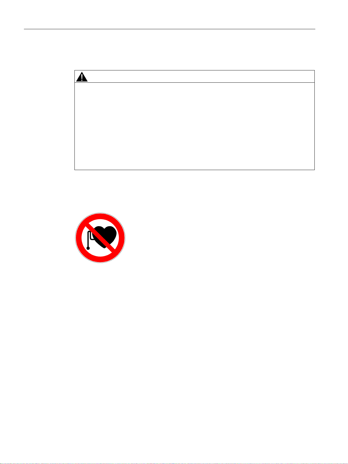
Electromagnetic fields are generated during operation of electrical power engineering
equipment, such as transformers, converters, and motors.
Electromagnetic fields can interfere with electronic devices, which could cause them to
malfunction.
For example, the operation of heart pacemakers can be impaired, potentially leading to
damage to a person's health or even death. Steps must be taken, therefore, to ensure that
persons with heart pacemakers cannot enter these areas.
The plant operator is responsible for taking appropriate measures (labels and hazard
warnings) to adequately protect operating personnel and others against any possible risk.
● Observe the relevant nationally applicable health and safety regulations or the applicable
national regulations in the country of installation.
● Display adequate hazard warning notices on the installation.
● Place barriers around hazardous areas.
● Take measures, e.g. using shields, to reduce electromagnetic fields at their source.
● Make sure that personnel are wearing the appropriate protective gear.
SINAMICS DCP
20 Operating Instructions, 05/2016, A5E34382853K
Page 21

Safety notes
2.3
Notes on plant safety
Requirements
2.3 Notes on plant safety
The operating company is responsible for the plant safety.
Ensure that:
● Basic planning activities and all work associated with transport, assembly, installation,
commissioning, maintenance and repair are performed exclusively by qualified personnel
or by experts assigned responsibility.
● The entire product documentation must always be available for all of the work that is
performed.
● The technical data and specifications regarding the permissible installation, connection,
environmental and operating conditions are always consequentially observed.
● The setup and safety regulations specific to this machine are observed and personal
safety precautions taken.
● It is prohibited for unqualified persons to work on these devices or in their vicinity.
SINAMICS DCP
Operating Instructions, 05/2016, A5E34382853K
21
Page 22
Safety notes
2.4
ESD-sensitive components
NOTICE
Electrostatic discharge
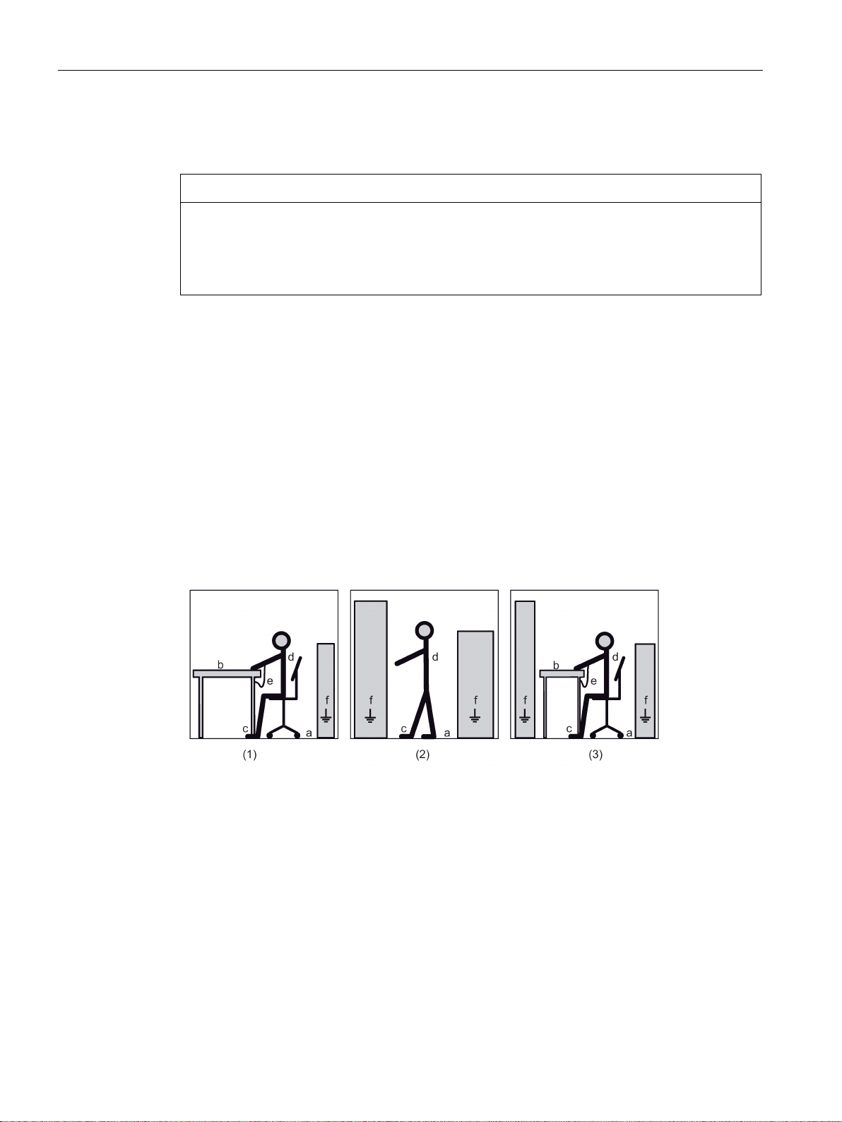
(1) = sitting
(2) = standing
(3) = standing/sitting
ESD protective measures
a = conductive floor surface
b = ESD table
c = ESD shoes
d = ESD overall
e = ESD wristband
f = cabinet ground connection
2.4 ESD-sensitive components
Electronic modules contain components that can be destroyed by electrostatic discharge.
These modules can be easily destroyed if they are not handled properly.
To protect your equipment against damage, follow the instructions given below.
● Never touch electronic modules unless absolutely necessary in the course of
maintenance and repair procedures.
● If the modules have to be touched, the body of the person concerned must be
electrostatically discharged immediately beforehand and be grounded.
● Electronic modules should not be brought into contact with electrically insulating materials
such as plastic foil, plastic parts, insulating table supports or clothing made of synthetic
fibers.
● Always place electrostatic sensitive devices on conductive bases.
● Always store and transport electronic modules or components in conductive packaging
(e.g. metallized plastic or metal containers).
The necessary ESD protective measures for electrostatically sensitive devices are illustrated
once again in the following drawings:
Image 2-1 ESD protective measures
SINAMICS DCP
22 Operating Instructions, 05/2016, A5E34382853K
Page 23

3
Area of application
Design
A SINAMICS DCP is used to control the electrical power flow between two direct current
systems. The device can be operated with current control or voltage control.
The main application of the SINAMICS DCP is to control the electrical power flow:
● from a DC link (the input side, terminals P1 and N1) into a stationary battery (the output
● from a battery (the output side, terminals P2 and N2) back to the DC link (the input side,
The power flow in both directions (from the DC link to the battery and from the battery to the
DC link) is called bidirectional.
side, terminals P2 and N2).
terminals P1 and N1).
The voltages in the two DC circuits are independent of one another.
The electrical power flow, controlled by a signed current setpoint specification, is possible
irrespective of the voltages in the two DC circuits (in the nominal range).
The integration of a SINAMICS DCP in a complete technical system is illustrated in Chapter
Block diagram with connection suggestion (Page 40).
The SINAMICS DCP are compact devices and contain power units and open-loop/closedloop control electronics.
The open-loop/closed-loop control electronics comprise several modules.
The module visible when the front plate is removed is called CUD (Control Unit DC).
LEDs are fitted on the CUD and other modules. They are not visible externally. They are not
relevant for the user, they are only used for diagnostics by SIEMENS experts.
The power units are made up of semiconductor switches; the heat sink is grounded.
The devices are forced-ventilated, the air flow is from the bottom to the top.
The minus cable is led from the input to the output, the current is controlled in the plus
branch.
The devices are only approved for cabinet mounting, vertical installation.
Communication with the devices is via fieldbus (PROFIBUS or PROFINET) during normal
operation and STARTER for the parameter assignment and diagnostics.
SINAMICS DCP
Operating Instructions, 05/2016, A5E34382853K
23
Page 24

Description
Additional components
CBE20 additional module
PROFINET
Memory card
For communication between two Control Units via DRIVE-CLiQ
●
– The CBE20 additional module is inserted in the option module slot of the CUD. It
enables the SINAMICS DCP to participate in a
●
– The memory card enables the functions described in Chapter Memory card functions
(Page 113).
●
seeOALINK Function Manual:
https://support.industry.siemens.com/cs/ww/en/view/109477831)
(
network as a slave.
,
SINAMICS DCP
24 Operating Instructions, 05/2016, A5E34382853K
Page 25

4
4.1
Device order numbers
Rated output
Rated direct current
Rated DC voltage
Order number
MLFB
120 kW
200 A
600 V
6RP0010-1AA32-0AA0
30 kW 50 A 600 V 6RP0000-0AA25-0AA0
SINAMICS DCP
Operating Instructions, 05/2016, A5E34382853K
25
Page 26
Preparations for use
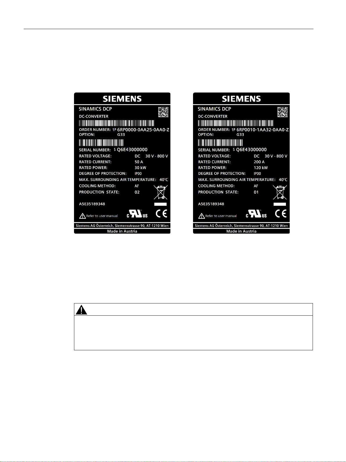
4.2
Rating plate
Symbolic illustration of a rating plate for
a 30 kW device
Symbolic illustration of a rating plate for
a 120 kW device
Explanation:
WARNING
Hazardous Voltage
4.2 Rating plate
The rating plate contains the most important technical data and the serial number.
It is attached to the front cover.
(1P) ... Article number
(S) ... Serial number
A5E ... SIEMENS-internal article number
There is a warning notice below the rating plate on the front cover about the hazardous
voltage present for up to 5 minute at the device after it has been disconnected from the
power supply.
SINAMICS DCP
26 Operating Instructions, 05/2016, A5E34382853K
Page 27

Preparations for use
4.2 Rating plate
Image 4-1 Symbolic illustration of the warning label
SINAMICS DCP
Operating Instructions, 05/2016, A5E34382853K
27
Page 28

Preparations for use
4.3
Ordering information for options and accessories
Option
Order codes
directly on the CUD.
CBE20 PROFINET
G33
Memory card
S03
Option
Order codes
Coated modules
Relative/absolute humidity 5% to 95% / 1 to 29 g/m3 for ambient or coolant temperature ≤
(2 years) after being delivered
(2½ years) after being delivered
(3 years) after being delivered
(3½ years) after being delivered
(4 years) after being delivered
(5 years) after being delivered
Power connections from below
M792)
1)
2)
Can only be ordered for the 120 kW device.
4.3 Ordering information for options and accessories
Ordering information for options with order codes
Table 4- 1 Control Unit CUD options
Terminal Module Cabinet (TMC) can be snapped onto a 35 mm mounting rail. Enables the
simple connection of the CUD standard signals (X177) via spring-loaded terminals in an easily accessible area of the control cabinet. The CUD is equipped with an adapter board. Terminal Module Cabinet and connecting cable (3 m) are supplied as separate items.
Note:
In the device version with option G63, the X177 terminal connections are no longer available
Table 4- 2 Further options
Coated modules increase the robustness against climate influences:
•
30° C.
• ≤ 60% when SO2 and H2S is present and/or for ambient or coolant temperature 30° C to
40° C.
• Oil mist, salt mist, ice formation, condensation, dripping water, spraying water, splashing
water and water jets are not permitted.
Extension of the warranty conditions by 12 months to a total of 24 months
G63
M08
Q80
*1)
Extension of the warranty conditions by 18 months to a total of 30 months
Extension of the warranty conditions by 24 months to a total of 36 months
Extension of the warranty conditions by 30 months to a total of 42 months
Extension of the warranty conditions by 36 months to a total of 48 months
Extension of the warranty conditions by 48 months to a total of 60 months
Can be ordered as an option for 30 kW devices, included in the standard scope of delivery for 120 kW devices.
SINAMICS DCP
28 Operating Instructions, 05/2016, A5E34382853K
Q81
Q82
Q83
Q84
Q85
Page 29

Preparations for use
Ordering information for accessories
Item
Order number
CBE20 PROFINET
6SL3055-0AA00-2EB0
STARTER commissioning tool
6SL3072-0AA00-0AG0
4.3 Ordering information for options and accessories
Table 4- 3 Order numbers for accessories
Memory card (corresponds to spare part for option S03) 6RX1800-0AS50
SINAMICS DCP
Operating Instructions, 05/2016, A5E34382853K
29
Page 30

Preparations for use
4.3 Ordering information for options and accessories
SINAMICS DCP
30 Operating Instructions, 05/2016, A5E34382853K
Page 31

5
The SINAMICS DCP is only designed for cabinet mounting. It must be mounted vertically.
The mandatory cooling clearances are indicated by the dotted line. The arrangement of the
fixing positions is shown in the following:
Image 5-1 Dimensions and fixing positions for 30 kW device (from product version 02)
SINAMICS DCP
Operating Instructions, 05/2016, A5E34382853K
31
Page 32

Mounting
Image 5-2 Dimensions and fixing positions for 120 kW device
The area below the device must be unobstructed and allow sufficient supply air.
The area above the device must allow the air outlet and the air outlet openings of the device
must be unobstructed.
For the 30 kW device, the lateral clearance to other components (also for the attachment of
further SINAMICS DCPs) must be at least 20 mm. This is not required for the 120 kW
device.
SINAMICS DCP
32 Operating Instructions, 05/2016, A5E34382853K
Page 33

Mounting
Note
For cabinet
if the power rating is fully utilized. This fan must be designed for the "fan air flow" (seeDevice
data
The customer must ensure that power cables are clamped nor further than 300 mm from
their termination.
designs with degree of protection greater than IP20, an additional fan is required
(Page 287)) of the device in question.
Image 5-3 120 kW device with mounted transport aid
The 120 kW device is delivered with 3 metal brackets, which are used as a transport aid (in
figure 5-3, shown in red). These have to be removed before mounting and disposed of as
scrap metal.
SINAMICS DCP
Operating Instructions, 05/2016, A5E34382853K
33
Page 34

Mounting
SINAMICS DCP
34 Operating Instructions, 05/2016, A5E34382853K
Page 35

6
WARNING
DANGER
The devices are operated with hazardous voltages.
All connection work must be carried out while the cabinet is de-energized.
Only qualified personnel who are familiar with all the safety instructions in these Operating
Instructions, as well as the assembly, installation, operating, and maintenance instructions,
should carry out work on these units.
Failure to observe this warning information can result in death, serious injury, or extensive
material damage.
Connecting the unit incorrectly can lead to it being damaged or destroyed.
When handling the unit while it is open, remember that live parts are exposed. The unit
must only be operated with the front covers provided by the factory fitted. When required,
additional covers should be provided in the control cabinet.
This product can cause a direct current in the protective ground conductor. When a residual
current device (RCD) or a residual current monitor (RCM) is used for protection in the event
of direct or indirect contact, only an RCD or RCM of type B is permissible on the power
supply side of this product.
SINAMICS DCP
Operating Instructions, 05/2016, A5E34382853K
35
Page 36

Electrical connection
6.1
EMC-compliant installation
6.1.1
Basic information about EMC
What is EMC?
Interference emissions and interference immunity
Product standard EN 61800-3
first environment
second environment
6.1 EMC-compliant installation
EMC stands for "electromagnetic compatibility" and describes "the capability of a device to
function satisfactorily in an electromagnetic environment without itself causing interference
unacceptable for other devices in the environment". Therefore, the various units used should
not cause interference to one another.
Within the context of the EMC Directive, the SINAMICS DCP units described in this
document are not "units" at all, but are instead "components" that are intended to be
installed in an overall system or overall plant. For reasons of clarity, however, the generic
term "units" is used in many cases.
EMC is dependent upon two properties demonstrated by the units involved in the system:
interference emissions and interference immunity. Electrical units may be sources of
interference (senders) and/or potentially susceptible equipment (receivers). Electromagnetic
compatibility is ensured when the existing sources of interference do not impair the function
of potentially susceptible equipment.
A unit may even be a source of interference and potentially susceptible equipment at the
same time: For example, the power unit of a converter should be viewed as a source of
interference and the control unit as potentially susceptible equipment.
EN 61800-3 defines different limits depending on the installation site of the system, referred
to as the first and second environments.
Residential buildings or locations at which the system is directly connected to a public lowvoltage network without an intermediate transformer are defined as the
The term
basically industrial areas which are powered from the medium-voltage network via their own
transformers.
refers to all locations outside residential areas. These are
.
SINAMICS DCP
36 Operating Instructions, 05/2016, A5E34382853K
Page 37

Electrical connection
Category C1:
Systems for rated voltages < 1000 V for unlimited use in the first enviro
ment
Category
Stationary systems for rated voltages < 1000 V for use in the second env
ronment. Use in the first environment is possible if the system is operated
and installed by qualified personnel. The warning information and install
tion instructions supplied by the manufacturer must be observed.
Category C3:
Systems for rated voltages < 1000
ronment
Category C4:
Systems for rated voltages
complex systems in the second environment
6.1 EMC-compliant installation
Image 6-1 Definition of the first and second environments
Four different categories are defined in EN 61800-3 depending on the location and the
power:
C2:
≥ 1000 V or for rated currents ≥ 400 A for use in
V for exclusive use in the second envi-
The figure below shows how the four categories are assigned to the first and second
environments:
Image 6-2 Definition of categories C1 to C4
n-
i-
a-
SINAMICS DCP
Operating Instructions, 05/2016, A5E34382853K
37
Page 38

Electrical connection
EN 61800-3
EN 61000-6-2
EN 61000-6-4
WARNING
6.1.2
EMC-compliant installation of SINAMICS DCP (installation instructions)
General information
Grounding of the DC link
not
Rules for EMC-compliant installation
1 Interconnect all metallic parts of the control cabinet highly conductively and with a large
contact area. (not paint on paint!). Use contact or scratch washers if necessary. The
cabinet door must be connected to the cabinet using the shortest possible ground strips
(at the top, center, and bottom).
2 Contactors, relays, solenoid valves, electromechanical operating hours counters, etc.,
in the cabinet and
quenching combinations such as RC elements, varistors, and diodes. These must be
connected directly at the appropriate coil.
3
Whenever possible, lead signal cables
into the cabinet at one level only.
4 Unshielded cables in the same circuit (supply/return conductors) must be twisted where
possible, or the area between them must be minimized, to avoid creating loop antennas
unnecessarily.
5 Connect spare wires to the cabinet ground
shielding effect.
6 Avoid unnecessary cable lengths in order to keep coupling capacities and inductances
low.
7 Crosstalk is generally reduced if the cables are laid close to the control cabinet ground.
Therefore, do not route cables freely around the cab
sible to the cabinet enclosure / mounting plates. This also applies to spare cables.
6.1 EMC-compliant installation
SINAMICS DCP devices satisfy the requirements for interference emission and interference
immunity defined in
generic standards
for the second environment (Category C3) and those in the
and
.
In a residential environment, this product can cause high-frequency disturbances, which
may make interference suppression measures necessary.
In order to ensure electromagnetic compatibility (EMC) in rugged electrical environments and
adhere to the standards required by the relevant legislating body, the EMC rules listed below
should be followed during the construction and installation stages.
The DC link does
have to be grounded. (for a 30 kW device from product version 02).
- where applicable - in neighboring cabinets - must be provided with
1)
2)
at both ends. This achieves an additional
SINAMICS DCP
38 Operating Instructions, 05/2016, A5E34382853K
inet, but lay them as close as pos-
Page 39

Electrical connection
8 Signal and power cables must be physically separated (to prevent coupling paths).
Minimum clearance: 20 cm should be aimed at. If it i
rate the signal cable and electric power cable, the signal cable must be decoupled e
ther using a partition or by routing it in a metal conduit. The partition or metal conduit
must be grounded at several points. If it is no
cables crossing, make sure that they cross at right angles only.
9 Ground the shields of digital signal cables at both ends (source and destination), ensu
ing maximum contact area and good conductivity. In the event
bonding between the shield connections, run an additional equalizing conductor with a
cross
shield current. Generally speaking, the shields may also be
enclosure (ground)
even outside the control cabinet. Foil shields should be avoided, as they are are at
least 5 times less effective than braided shields.
10 Shields
tial bonding is good (this must be done over a large area with good conductivity). It can
be assumed that equipotential bonding is good if all metal parts are well interconnected
and the electronics components are supplied from a single source.
Footnotes
1)
Signal cables are defined as:
Digital signal cables, e.g. cables for incremental encoders
Analog signal cables, e.g. ±10 V setpoint cable
Serial interfaces, e.g. PROFIBUS and PROFINET
2)
Generally speaking, "ground" refers to all metallic conductive parts that can be co
nected to a protective conductor, such as the cabinet enclosure, motor enclosure, or
foundation ground.
6.1 EMC-compliant installation
s not possible to physically sepa-
i-
t possible to prevent signal and power
r-
of poor equipotential
-section of at least 10 mm² parallel to the shield for the purpose of reducing the
connected to the cabinet
2)
at several points. The shields can be connected several times
for analog signal cables may be connected to ground at both ends if equipoten-
n-
SINAMICS DCP
Operating Instructions, 05/2016, A5E34382853K
39
Page 40

Electrical connection
6.2
Block diagram with connection suggestion
6.2 Block diagram with connection suggestion
Image 6-3 Block diagram with connection suggestion
SINAMICS DCP
40 Operating Instructions, 05/2016, A5E34382853K
Page 41

Electrical connection
6.2 Block diagram with connection suggestion
The block diagram above shows a (maximum) configuration for the SINAMICS DCP together
with possible interfaces to a higher level controller.
● Fuses: See Chapter Components (Page 43)
● Precharging (precharging interface: precharging resistors and fuses): See Chapter
Precharging of the DC links (Page 240)
● Main contactors: See Chapter Components (Page 43)
● The connections "from the previous DCP" and "to the next DCP" are only required if
multiple SINAMICS DCPs are switched in parallel: See Chapter Parallel connection of
multiple SINAMICS DCPs (Page 269)
To prevent coupling of external interference into the cabinet, the shields for the cables used
must be grounded extensively as close as possible to the point of entry into the cabinet.
Suitable shield buses or comb bars can be used here.
These busbars must be connected conductively and extensively to the cabinet housing.
Image 6-4 Shield connection for an electric power cable (e.g. connection to DC link, to the battery, or to a PV field) at
point of entry into the cabinet
SINAMICS DCP
Operating Instructions, 05/2016, A5E34382853K
41
Page 42

Electrical connection
6.2 Block diagram with connection suggestion
Image 6-5 Shield connection for the signal cables in the cabinet
The following rules apply for the connection cables:
● All cables that leave the cabinet system must be "shielded".
● Cables inside the cabinet do not have to be "shielded".
SINAMICS DCP
42 Operating Instructions, 05/2016, A5E34382853K
Page 43

Electrical connection
6.3
Components
Fuses
Suggested type
Line contactors
Recommended type
Precharging resistors
Recommended type
Note
Using this precharging resistor will result in the follow
30 kW device: 65 ms
120 kW device: 600
This must be taken into account in the parameterization (p55355).
6.3 Components
The device must be protected by DC fuses on the input side and output side.
For the 30 kW device:
Siemens PV fuse 63 A with designation 3NE1218-4
Fuse holder: Siemens 3NH7262-4KK01
Alternative fuse (with UL certification): Ferraz Shawmut/Mersen: A150X60-4
For the 120 kW device:
Siemens PV fuse 250 A with designation 3NE1227-4D
Fuse holder: Siemens 3NH7260-4
Alternative fuse (with UL certification): Ferraz Shawmut/Mersen: A150X250-4
Relevant to the 30 kW device:
Gigavac HX21 C A (with UL certification)
This type is only a single-pole contactor, which means that, to switch two poles, 2 contactors
are required for each current path.
The power contactors must be able to handle 1000 V and 50 A.
Relevant to the 120 kW device:
Gigavac HX21 C A (with UL certification)
This type is only a single-pole contactor, which means that, to switch two poles, 2 contactors
are required for each current path.
The power contactors must be able to handle 1000 V and 200 A.
CAV 150 C 100R 800, manufacturer: Danotherm company
ing precharging times:
ms
SINAMICS DCP
Operating Instructions, 05/2016, A5E34382853K
43
Page 44

Electrical connection
Precharging contactors
Recommended type
Note
With the recommended series resistor, the max. contact load of 10 A is not exceeded.
Pre-charge circuit fuse
6.3 Components
High-voltage relay H-507
Type code H00-04507/11-001128-002/005.00
Coil voltage 24 V
Manufacturer: Hengstler company
or
High-voltage relay RL 42
Coil voltage 24 V
Manufacturer: SPS Electronic Company
Alternatively, a UL-recognized type can be used
Gigavac P115 C D A
. This type is only implemented as single pole configuration. This means that 2 contactors
are required for each circuit if you wish to switch two poles.
Cylindrical fuse-links operating class gPV
10 x 38 4 A 1000 V 1.4 B 3NW6 004-4
Cylindrical fuse holder without signal detector
1P 25 10 x 38 1 B 3NW7 013-4
SINAMICS DCP
44 Operating Instructions, 05/2016, A5E34382853K
Page 45

Electrical connection
6.4
Terminals and connectors
Power connections for 30 kW device
6.4 Terminals and connectors
● The DC input power connection is on the bottom left of the device
● The DC output power connection is on the bottom right of the device
● The ground connection is on the bottom left of the device
Image 6-6 Connection area for power connections for the 30 kW device
SINAMICS DCP
Operating Instructions, 05/2016, A5E34382853K
45
Page 46

Electrical connection
Power connections for the 120 kW device
6.4 Terminals and connectors
● The DC input and DC output power unit connections are on top on the device, or on the
bottom for the M 79 option.
● The ground connection is located at the top and bottom of the device
Image 6-7 Connection area for power connections for the 120 kW device
SINAMICS DCP
46 Operating Instructions, 05/2016, A5E34382853K
Page 47

Electrical connection
Power connections
P1
Input circuit: Plus cable
N1
Input circuit: Minus cable
N2
Output circuit: Minus cable
NOTICE
Connection cables
30 kW device
Note
The sheaf diameter of the cable must not be greater than 10 mm.
Recommended connection cable:
RADOX® solar cable
6.4 Terminals and connectors
P2 Output circuit: Plus cable
Remark: On the 120 kW device, connections N1 and N2 are combined to form a busbar with
designation N.
Tightening torque of the nuts for the power connections: 13 Nm.
For reasons of safety, multiple use of the power connections is not permitted. In other
words, you must not place several cable lugs on top of each other and screw them
together. If it is necessary to loop through the power connections (for example, when
connecting several SINAMICS DCPs in parallel), you must use suitable distribution
terminals, which you mount in the cabinet.
The cable used must satisfy the requirements of the recommended connection cable.
●
Cross section: 10 mm
Order no.: 12537897
2
SINAMICS DCP
Operating Instructions, 05/2016, A5E34382853K
47
Page 48

Electrical connection
120 kW device
Recommended connection cable:
Cable with shield:
SIENOPYR(90) (N)HXSGAFCHXÖ 1.8/3 kV
Cable without shield:
SIENOPYR(90) (N)HXSGAFHXÖ 1.8/3 kV
Ground connection
6.4 Terminals and connectors
●
Cross section: 50 mm2
Order no.: 5DF9 660
●
Cross-section:
Order no.: 5DF8 153
50 mm2
The device must be grounded. The device has a ground connection, identified by a
grounding symbol.
30 kW device: Tightening torque of the screw for the protective conductor: 6 Nm.
120 kW device: Tightening torque of the screw nut for the protective conductor: 13 Nm.
SINAMICS DCP
48 Operating Instructions, 05/2016, A5E34382853K
Page 49

Electrical connection
Terminal block for the 24 V DC power supply and switching contacts
6.4 Terminals and connectors
There is a terminal block with 10 terminals either on or in the device (see following figures).
Image 6-8 Connection area for 24 V supply and switching contacts for 30 kW device
For the 120 kW device, the terminal block for the power supply and switching contacts is
only accessible after first removing the front panel.
SINAMICS DCP
Operating Instructions, 05/2016, A5E34382853K
49
Page 50

Electrical connection
Terminal arrangement
1
P24 V ext
External power supply
24 VDC plus cable
2
M ext
External power supply
24 VDC minus cable
3
VLSE1
NO contact for contactor control:
Precharging contactor input
4
VLSE2
NO contact for contactor control:
Precharging contactor input
5
HLSE1
NO contact for contactor control:
Line contactor input
6
HLSE2
NO contact for contactor control:
Line contactor input
7
VLSA1
NO contact for contactor control:
Precharging contactor output
8
VLSA2
NO contact for contactor control:
Precharging contactor output
6.4 Terminals and connectors
Image 6-9 Connection area for 24 V supply and switching contacts for 120 kW device
SINAMICS DCP
50 Operating Instructions, 05/2016, A5E34382853K
Page 51

Electrical connection
9
HLSA1
NO contact for contactor control:
Line contactor output
10
HLSA2
NO contact for contactor control:
Line contactor output
Communication connections
①
PROFIBUS cable
6.4 Terminals and connectors
Terminal type: Spring-loaded terminal
● Type: PELV 24 V circuit
● Voltage tolerance of the P24 V ext: 18 V to 30 V for 30 kW devices, In = 5 A
for 120 kW devices, In = 20 A
● Conductor cross-sections: 1.5 to 2.5 mm
2.
For 120 kW devices, for connections P24 V ext and M ext, a cross-section of 2.5 mm2
must be used.
Contact rating of the "NO contact for the contactor control": 2 A at 30 VAC/DC resistive.
The cables for PROFIBUS or PROFINET must be connected inside the device. The front
cover must be removed for this.
● The PROFIBUS connector X126 is on the CUD module. The cable can be led out at the
bottom through the intended aperture.
● The PROFINET connector X1400 is on the CBE20 module. The cable can be brought out
at the top through the opening provided for this purpose.
SINAMICS DCP
Operating Instructions, 05/2016, A5E34382853K
Image 6-10 PROFIBUS connection for the 30 kW device or 120 kW device
51
Page 52

Electrical connection
①
PROFINET cable
Terminals on the CUD
-X178, -X179:
Flexible with end sleeve with/without plastic sleeve: 0.25 - 1.5 / 0.25 - 0.75 mm2
Stripping length
10 mm
-XR1,- XS1, -XT1:
Type
MSTB 2.5 / CIF plug-in terminal
end sleeve with/without plastic sleeve: 0.25 - 2.5 / 0.25 - 2.5 mm2
Stripping length
7 mm
Tightening torque
0.5 - 0.6 Nm
-X126:
Type
Submin D, 9-pin
6.4 Terminals and connectors
Image 6-11 PROFINET connection for the 30 kW device or 120 kW device
The CUD terminals are usually not required for the operation of the SINAMICS DCP.
Table 6- 1 Terminal type
Type FMC 1.5 plug-in terminal
Conductor size Rigid/flexible/conductor sizes (mm2/mm2/AWG): 0.2 - 1.5 / 0.2 - 1.5 / 24 - 16
Conductor size Rigid/flexible/conductor sizes (mm2/mm2/AWG): 0.2 - 2.5 / 0.2 - 2.5 / 24 - 12 flexible with
SINAMICS DCP
52 Operating Instructions, 05/2016, A5E34382853K
Page 53

Electrical connection
-X100, -X101:
Type
Modular jack 8/4 (RJ45)
6.4 Terminals and connectors
SINAMICS DCP
Operating Instructions, 05/2016, A5E34382853K
53
Page 54

Electrical connection
Terminals on the connector board
Analog inputs (assignable inputs)
2
4
6
8
Digital inputs (assignable inputs)
internal supply in relation to internal ground
11
DI 0
Digital input 0
12
DI 1
Digital input 1
13
DI 2
Digital input 2
14
DI 3
Digital input 3
Digital inputs/outputs (assignable inputs/outputs)
/output 4
If overload occurs: Alarm A60018
/output 5
/output 6
19
DO 0
Digital output 0
If overload occurs: Alarm A60018
20
DO 1
Digital output 1
21
DO 2
Digital output 2
22
DO 3
Digital output 3
Analog inputs, setpoint inputs (assignable inputs)
6.4 Terminals and connectors
See also Table 8-8 Overview of inputs and outputs (Page 133).
Table 6- 2 Assignment, terminal -X177
Terminal
-X177
1
3
5
7
9
10
15 DI/DO 4 Digital input
16 DI/DO 5 Digital input
17 DI/DO 6 Digital input
18 DI/DO 7 Digital input
Function Technical specifications
AI 3 +
AI 3 -
AI 4 +
AI 4 -
AI 5 +
AI 5 -
AI 6 +
AI 6 -
DC
24 V
Analog input 3 Input type (signal type): Differential input ±10 V; 150 kΩ resolution
Analog input 4
Analog input 5
Analog input 6
24 V supply (output) 24 VDC, short-circuit proof
/output 7
approx. 5.4 mV (±11 bits) common-mode controllability: ±15 V
Max. load 200 mA (terminals 9 and 10 combined),
H signal: +15 V to +30 V
L signal: – 30 V to +5 V or terminal open circuit
8.5 mA at 24 V
Type, parameterizable input/output
Input characteristics:
H signal: +15 V to +30 V
L signal: 0 V to +5 V or terminal open
8.5 mA at 24 V
Output characteristics:
H signal: +20 V to +26 V
L signal: 0 to +2 V
short-circuit proof; max. current carrying capacity: 100 mA per DO;
max. total load of all DO (CUD left -X177:15-22 + CUD
right -X177:15-22): 800 mA
Internal protection circuit (free-wheeling diode)
23 ... 24 M Ground, digital
SINAMICS DCP
54 Operating Instructions, 05/2016, A5E34382853K
H signal: +20 V to +26 V
L signal: 0 to +2 V
short-circuit proof; max. current carrying capacity: 100 mA per DO;
max. total load of all DO (CUD left -X177:15-22 + CUD
right -X177:15-22): 800 mA
Internal protection circuit (free-wheeling diode)
Page 55

Electrical connection
Common-mode controllability: ±15 V
Common mode controllability ±15 V
Reference voltage
32
N10
33, 34
M
Ground, analog
Terminals not used
35, 36
M
Ground, digital
37 Not used
38 Not used
39 Not used
40 Not used
Terminals not used
41
Supply
42
Ground
44
Not used
46
Not used
47
Not used
48
Not used
Analog outputs (assignable outputs)
49
AO 0
Analog output 0
50 M Ground, analog
51
AO 1
Analog output 1
52 M Ground, analog
Connections for temperature sensors
53
Temp1
54
Temp2 (sense cable)
6.4 Terminals and connectors
25
26
27
28
29
30
31
43 Not used
AI 0 +
AI 0 -
AI 1 +
AI 1 -
AI 2 +
AI 2 -
P10
Analog input 0 Parameterizable input type (signal type):
Differential input ±10 V; 150 kΩ
Analog input 1 Current input 0 mA - 20 mA; 300 Ω or 4 mA - 20 mA; 300 Ω resolu-
tion approx.
Analog input 2 Input type (signal type):
- Differential input ±10 V; 150 kΩ
Resolution approx. 0.66 mV (±14 bits)
Reference voltage ±10 V
(output)
Tolerance ±1% at 25° C Stability 0.1% per 10° K
10 mA short-circuit proof
+13.7 V to +15.2 V, 300 mA short-circuit proof
(electronically protected)
If overload occurs: Alarm A60018
0.66 mV (±14 bit)
45 Not used
±10 V, max. 2 mA short-circuit proof, resolution ±15 bits
Sensor according to P50490 (see SINAMICS DCP List Manual). The
cable to the temperature sensor must be shielded and connected to
SINAMICS DCP
Operating Instructions, 05/2016, A5E34382853K
55
Page 56

Electrical connection
ground at both ends. The cables from the Temp 1 and Temp 3 con-
56 M Ground, analog
6.4 Terminals and connectors
55 Temp3
nections to the temperature sensor must have approximately the
same length.
The sense cable (Temp 2) is used for compensating for the cable
resistances. If you are not using a sense cable, connect terminals 54
and 55.
Connection with / without sense cable:
SINAMICS DCP
56 Operating Instructions, 05/2016, A5E34382853K
Page 57

Electrical connection
6.5
Additional system components
6.5.1
Option Board: Communication Board EtherNet CBE20
6.5.1.1
Description
Note
By inserting the CBE20, the IF1 communication channel switches
PROFINET. Communication is therefor no longer possible via PROFIBUS.
6.5.1.2
Safety instructions
NOTICE
Damage or malfunctions of the Option Board by inserting and withdrawing during operation
NOTICE
6.5 Additional system components
The SINAMICS DCP can be connected to PROFINET using the Communication Board
CBE20 interface module. The module supports PROFINET IO with Isochronous Realtime
EtherNet (IRT) and PROFINET IO with RT. Mixed operation is not permissible. PROFINET
CBA is not supported.
The option board has an X1400 interface with four ports for communication.
The Communication Board CBE20 allows SINAMICS Link connections and the connection to
EtherNet/IP to be established.
over from PROFIBUS to
Withdrawing and inserting the Option Board during operation can damage it or cause it to
malfunction.
• Only withdraw or insert the Option Board when the Control Unit is de-energized.
The CBE20 must only be operated by qualified personnel. The ESD information must be
observed.
SINAMICS DCP
Operating Instructions, 05/2016, A5E34382853K
57
Page 58

Electrical connection
6.5.1.3
Interface description
Overview
MAC address
6.5 Additional system components
Image 6-12 Interface description CBE20
The MAC address of the EtherNet interface is located on the upper side of the board.
SINAMICS DCP
58 Operating Instructions, 05/2016, A5E34382853K
Page 59

Electrical connection
X1400 EtherNet interface
Pin
Signal name
Technical specifications
1
RXP
Receive data +
3
TXP
Transmit data +
4
Reserved, do not use
5
Reserved, do not use
6
TXN
Transmit data -
7
Reserved, do not use
8
Reserved, do not use
shell
Connector type: RJ45 socket
Cable and connector types
6.5.1.4
Meaning of the LEDs
LED
Color
State
Description
missing or defective).
light
activity).
Yellow
Flashing light
Data is being received or sent at port x.
6.5 Additional system components
Table 6- 3 X1400 EtherNet, Ports 1-4
2 RXN Receive data -
Screened back-
M_EXT Screen, permanently connected
For diagnostic purposes, the ports have one green and one yellow LED (for a description,
see Chapter Meaning of the LEDs (Page 59)).
Information on PROFINET cables and connectors can be found in the following catalog:
Industrial Communication
Catalog IK PI
Table 6- 4 Meaning of the LEDs at ports 1 to 4 of the X1400 interface
Link port - Off Electronics power supply is missing or outside permissible tolerance range (link
Green Continuous
A different device is connected to port x and a physical connection exists.
Activity port - Off Electronics power supply is missing or outside permissible tolerance range (no
SINAMICS DCP
Operating Instructions, 05/2016, A5E34382853K
59
Page 60

Electrical connection
LED
Color
State
Description
IO Controller.
stitute clock is generated.
exchanged.
light
LED
Color
State
Description, cause
Remedy
Communication Board either defective or not inserted.
light
is taking place.
tion/configuration telegram.
6.5 Additional system components
Table 6- 5 Meaning of the Sync and Fault LEDs on the CBE20
Fault – Off If the link port LED is green:
The CBE20 is operating normally, data is being exchanged with the configured
Red Flashing
Continuous
light
Sync – Off If the link port LED is green:
Green Flashing light Control Unit task system is synchronized with the IRT clock and data is being
Continuous
• The response monitoring interval has elapsed.
• Communications is interrupted.
• The IP address is incorrect.
• Incorrect or no configuration.
• Incorrect parameter settings.
• Incorrect or missing device name.
• IO Controller not connected/switched off, although an EtherNet connection
has been established.
• Other CBE20 errors
CBE20 bus error
• No physical connection to a subnet/switch.
• Incorrect transmission rate.
• Full duplex transmission is not activated.
Control Unit task system is not synchronized with the IRT clock. An internal sub-
Task system and MC-PLL are synchronized with the IRT clock.
Table 6- 6 Meaning of the OPT LED on the Control Unit
OPT – OFF Electronic power supply is missing or outside permissible
tolerance range.
Green Continuous
Flashing light
0.5 Hz
Red Continuous
light
SINAMICS DCP
Communication Board is ready and cyclic communication
The Communication Board is ready, but cyclic communications is not running.
Possible causes:
• At least one fault is present.
• Communication is being established.
Cyclic communication via PROFINET has not yet been
established. However, non-cyclic communication is possible. SINAMICS is waiting for a parameteriza-
–
–
–
–
60 Operating Instructions, 05/2016, A5E34382853K
Page 61

Electrical connection
LED
Color
State
Description, cause
Remedy
CBE20 cannot be used in this state.
0.5 Hz
6.5 Additional system components
Flashing light
0.5 Hz
Flashing light
2 Hz
Orange Flashing light
The firmware update into the CBE20 has been completed
with an error.
Possible causes:
• The CBE20 is defective.
• The memory card for the Control Unit is defective.
There is a communications error between the Control Unit
and the CBE20.
Possible causes:
• The board was withdrawn after booting.
• The board is defective.
Firmware is being updated. –
–
Correctly insert the
board, if required,
replace.
SINAMICS DCP
Operating Instructions, 05/2016, A5E34382853K
61
Page 62

Electrical connection
6.5.1.5
Assembling the 30 kW device
6.5 Additional system components
Image 6-13 Assembling the CBE20
● Loosen the screw ①
● Detach and remove the front plate
● Loosen the screws
● Pull out the electronics rack unit
● Push the CBE20 into the option module interface (see Image 6-14 Assembling the
CBE20 (Page 63))
● Reinsert the electronics unit
● Tighten the screws
● Attach the front plate
● Tighten the screw
SINAMICS DCP
62 Operating Instructions, 05/2016, A5E34382853K
③
③ again
② again
③ again
②
④
④
Page 63

Electrical connection
Tool: Torx T10 screwdriver tightening torque 1 Nm.
6.5 Additional system components
Push the CBE20 into the option module interface ① on the CUD from above, and tighten the
screws ②.
Image 6-14 Assembling the CBE20
SINAMICS DCP
Operating Instructions, 05/2016, A5E34382853K
63
Page 64

Electrical connection
6.5.1.6
Assembling the 120 kW device
6.5 Additional system components
Image 6-15 Assembling the 120 kW device
● Release the 2 screws at the lower side of the device and remove the front panel
● Release the nuts
● Loosen the screws
● Remove the cover plate
● Push in the CBE20
● Tighten the screws
● Fasten the cover plate
● Screw on the bracket
● Re-attach the front panel and tighten the 2 screws at the lower side of the device
SINAMICS DCP
64 Operating Instructions, 05/2016, A5E34382853K
①, remove the bracket
③
③ (screw)
④
③ again
③
③
Page 65

Electrical connection
6.5.1.7
Technical data
Communication Board CBE20
6SL3055-0AA00-2EBx
Unit
Value
Max. current requirements (at 24 V DC)
ADC
0.1
Power loss
W
2.4
Weight
kg
< 0.1
6.5.2
Terminal Module Cabinet TMC (option G63)
6.5 Additional system components
Table 6- 7 Technical data
The Terminal Module Cabinet (TMC) enables the simple connection of the CUD standard
signals (X177) via spring-loaded terminals in an easily accessible area of the control cabinet.
See Chapter Ordering information for options and accessories (Page 28) for ordering data.
Image 6-16 Terminal Module Cabinet
The CUD is equipped with a "Cabinet Board".
During installation, connectors X1 and X2 on the adapter board must be connected to
connectors X1 and X2 on the TMC with the supplied cables (3 m). The cables must be laid in
a cable duct.
For terminal assignment, see Chapter Image 6-17 Terminal/connector arrangement on the
"Cabinet Board" (Page 67).
SINAMICS DCP
Operating Instructions, 05/2016, A5E34382853K
65
Page 66

Electrical connection
Module - Control Unit (CUD), option G63
A7100 terminal/connector arrangement - option G63
6.5 Additional system components
SINAMICS DCP
66 Operating Instructions, 05/2016, A5E34382853K
Page 67

Electrical connection
Modules for option G63
Terminal assignment for option G63
Terminal
X177_1, X177_2
Function
Description
1st terminal block (X177_1)
1, 2
AI 3 +, AI 3 -
Analog input 3
See X177.1 and 2
3, 4
AI 4 +, AI 4 -
Analog input 4
See X177.3 and 4
5, 6
AI 5 +, AI 5 -
Analog input 5
See X177.5 and 6
7, 8
AI 6 +, AI 6 -
Analog input 6
See X177.7 and 8
internal supply to digital ground and analog ground
11, 12, 13, 14
DI 0, 1, 2, 3
Digital input 0, 1, 2, 3
See X177.11, 12, 13, 14
6, 7
6.5 Additional system components
Image 6-17 Terminal/connector arrangement on the "Cabinet Board"
Image 6-18 Terminal arrangement on the "Terminal Module Cabinet (TMC)"
The technical data for terminals X177_1, X177_2 and X177_5 corresponds to the
specifications for terminal X177 on the Connector Board in the version without option G63,
see Table 6-2 Assignment, terminal -X177 (Page 54).
Table 6- 8 Assignment of the terminals on the Terminal Module Cabinet (TMC) (overview)
9, 10 24 VDC 24 V supply (output) 24 VDC, short-circuit proof
Max. load 200 mA (terminals 9, 10, 57, 58, 59 and
60 combined),
15, 16, 17, 18 DI/DO 4, 5, 6, 7 Digital input/output 4, 5,
SINAMICS DCP
Operating Instructions, 05/2016, A5E34382853K
See X177.15, 16, 17, 18
67
Page 68

Electrical connection
Terminal
X177_1, X177_2
Function
Description
19, 20, 21 22
DO 0, 1, 2, 3
Digital output 0, 1, 2, 3
setpoint
29, 30
AI 2 +, AI 2 -
Analog input 2
See X177.29 and 30
±10 V (output)
33, 34
M
Ground, analog
2nd terminal block (X177_2)
35, 36
M
Ground, digital
See X177.35 and 36
37, 38
Not used
- - 39, 40
Not used
-
-
41, 42
Not used
-
-
43, 44
Not used
-
-
45, 46
Not used
- - 47, 48
Not used
-
-
ground
ground
motor interface 1
56 M Ground, analog
See X177.56
internal supply to digital ground and analog ground
61, 62, 63, 64
M
Ground, digital
-
"Terminal Module Cabinet (TMC)" module
Terminal
X177_5
Function
Description
33, 34
M
Ground, analog
-
35, 36
M
Ground, digital
See X177.35 and 36
37, 38
RS485: TX+, TX-
Send cable +, -
See X177.37 and 38
6.5 Additional system components
See X177.19, 20, 21, 22, 23, 24
23, 24 M Ground, digital
25, 26 AI 0 +, AI 0 - Analog input 0, main
27, 28 AI 1 +, AI 1 - Analog input 1 See X177.27 and 28
See X177.25 and 26
31, 32 P10, N10 Reference voltage
See X177.31, 32, 33, 34
49, 50 AO 0, M Analog output 0, analog
51, 52 AO 1, M Analog output 1, analog
53, 54, 55 Temp 1, 2, 3 Temperature sensor,
See X177.49 and 50
See X177.51 and 52
See X177.53, 54, 55
57, 58, 59, 60 24 VDC 24 V supply (output) 24 VDC, short-circuit proof
Max. load 200 mA (terminals 9, 10, 57, 58, 59 and
60 combined),
Table 6- 9 Assignment of the terminals on the Cabinet Board (overview)
SINAMICS DCP
68 Operating Instructions, 05/2016, A5E34382853K
Page 69

Electrical connection
Terminal
X177_5
Function
Description
39, 40
RS485: RX+, RX-
Receive cable +, -
See X177.39 and 40
Note:
(TMC).
Open-loop and closed-loop control section
X177, X177_5 (for option G63):
Type
SPT 1.5 spring-loaded terminal
0.25-1.5 / 0.25-0.75 mm2 (stripped length 8 mm)
Stripped length
10 mm
X177_1, X177_2 (for option G63):
Type
Two-tier terminal with spring-loaded terminal PK 68
Connection capacity
Rigid/flexible 0.5-2.5 mm2
X178, X179:
Type
FMC 1.5 plug-in terminal
Flexible with end sleeve with/without plastic sleeve: 0.25-1.5 / 0.25-0.75 mm2
Stripped length
10 mm
6.5 Additional system components
"Cabinet Board" module
The terminals on X177_5 are connected in parallel to the terminals with the same name on the Terminal Module Cabinet
Table 6- 10 Terminal type, open-loop and closed-loop control section
Connection capacity Rigid/flexible/conductor sizes (mm2/mm2/AWG): 0.2-1.5 / 0.2-1.5 / 24-16
Flexible with end sleeve with/without plastic sleeve:
Connection capacity Rigid/flexible/conductor sizes (mm2/mm2/AWG): 0.2-1.5 / 0.2-1.5 / 24-16
SINAMICS DCP
Operating Instructions, 05/2016, A5E34382853K
69
Page 70

Electrical connection
6.5 Additional system components
SINAMICS DCP
70 Operating Instructions, 05/2016, A5E34382853K
Page 71

7
WARNING
NOTICE
This unit is subject to hazardous voltage levels and contains dangerous rotating machine
parts (fans). Failure to comply with these Operating Instructions can lead to death, serious
injury and material damage.
Only qualified personnel who are familiar with all the safety instructions in this description,
as well as the installation, operating, and maintenance instructions, should carry out work
on this unit.
Perfect, safe and reliable operation of the equipment assumes that it has been
professionally transported, stored, mounted and installed as well as correct operation and
servicing.
Even when all contactors are open, the device is still subject to dangerous electrical voltage
levels. The internal DC-link capacitors may still be charged. Before starting any service or
maintenance work, disconnect the device on both power unit sides (P1/N1 and P2/N2).
To operate the SINAMICS DCP, the front cover fixing screw must be tight.
These instructions are not exhaustive and, as such, cannot outline all the measures
required in order to operate the device safely. Where necessary, additional information or
instructions may be required for special applications. If you encounter specific problems
that have not been handled in enough detail for the purposes of the buyer, then please
contact your local Siemens office.
The use of non-approved parts for carrying out repair work on the device or handling of the
device by inadequately qualified personnel will result in dangerous conditions with the risk
of death, serious injury, or extensive damage to equipment. All safety measures listed in
these Operating Instructions, as well as all warning signs attached to the device, must be
followed.
Observe all the warning notices in Chapter Safety notes (Page 15) of these Operating
Instructions.
Before coming into contact with modules (and in particular the CUDs), the operator must be
electrostatically discharged in order to protect electronic components against high voltages
that are produced by electrostatic charging. The easiest way to do this is to touch a
conductive, grounded object immediately beforehand (for example, bare metal parts of
control cabinet).
Modules must not come into contact with highly insulating materials (such as plastic sheets,
insulated desktops, or articles of clothing manufactured from synthetic fibers).
Modules may be placed only on conductive surfaces.
SINAMICS DCP
Operating Instructions, 05/2016, A5E34382853K
71
Page 72

Commissioning
Note
During a data save operation initiated by the user, the electronics power supply for the
SINAMICS DCP must not be interrupted.
An active data save operation is indicated by the following
•
•
Interrupting the power supply while sa
parameter assignments. See also Chapter
"Memory card fun
actions:
The RDY LED flashes (see Chapter Description of the LEDs on the CUD (Page 247))
The BOP20 flashes
ving can lead to the loss of the current device
Memory card functions (Page 113), Section
ctions".
SINAMICS DCP
72 Operating Instructions, 05/2016, A5E34382853K
Page 73

Commissioning
7.1
Switching on
BOP20 display
CUD LED status
Start-up time 1)
DP1: Red
DP1: Red
DP1: -
DP1: -
Start-up with saved parameters (i.e. saved from RAM to ROM)
Note
If options are
start
Note
If an external memory card with previously saved data is plugged into the SINAMICS DCP
during start
ignments saved on the card
(see also Chapter
7.1.1
BOP20 status display during ramp-up
Displayed value
Meaning
0
Operation
10
Ready
20
Waiting for ramp-up
25
Waiting for automatic firmware update of DRIVE-CLiQ components
31
Commissioning software download active
33
Correcting/acknowledging topology error
7.1 Switching on
After the device is switched on (POWER ON, i.e. switching in the 24 V power supply), the
SINAMICS DCP powers up. Starting up to operating state 7.1 in the SINAMICS DCP with
the saved parameters (i.e. saved from RAM to ROM) takes approx. 45 s. Start-up without the
saved parameters (first commissioning) takes approx. 60 s.
Table 7- 1 SINAMICS DCP ramp-up times
Light on the BOP20 RDY: Red
- RDY: Orange
DP1: Red
Display "run up" RDY: Orange
Operating state 12.4 RDY: Green
Operating state 7.1 RDY: Green
1)
POWER ON
15 s
35 s
40 s
45 s
The status of the LEDs on the CUD (see also Chapter Description of the LEDs on the CUD
(Page 247)) can only be seen when the device cover is open.
being used and in the case of certain device configurations, the duration of
-up increases.
-up, the device ramps up based on the parameter ass
Memory card functions (Page 113)).
During ramp-up, the status of the ramp-up is briefly displayed on the BOP20.
SINAMICS DCP
Operating Instructions, 05/2016, A5E34382853K
73
Page 74

Commissioning
34
Terminating commissioning mode
35
Performing first commissioning
70
Initialization
80
Reset active
7.1 Switching on
99 Internal software error
The states listed above are automatically run through during the commissioning and are
normally not visible.
In the following exceptional cases, ramp-up is interrupted with display value 33. In this state,
the device can be parameterized via BOP20 and via STARTER:
● Differences have been identified between the reference and actual topology.
– Correct the topology (e.g. re-insert the TM component).
– Accept the actual topology into the reference topology by setting p9905=1 or p9905=2.
Ramp-up is continued.
● A memory card with a parameter data set which comes from a SINAMICS DCP with a
different MLFB, is inserted in the device.
– Accept the parameter data set by setting p9906=3. Ramp-up is continued.
SINAMICS DCP
74 Operating Instructions, 05/2016, A5E34382853K
Page 75

Commissioning
7.2
Commissioning using the BOP20 operator panel
7.2.1
Requirements
SINAMICS basics
BOP20 operator panel
Notation of the parameters
(oo)pxxxxx[ii]
for indexed parameters
(oo)pxxxxx
for non
7.2.2
Commissioning steps
〈1〉Access level and parameter filter
〈2〉Setting the installation altitude
p55100, installation altitude
〈3〉Setting the source for the control word
p840 signal source for starting/stopping
7.2 Commissioning using the BOP20 operator panel
If you are not yet familiar with SINAMICS basics (parameters, drive objects, BICO
technology, etc.), please read Chapter Basics (Page 107) before starting commissioning.
If you are not yet familiar with the BOP20 operator panel, please read Chapter Parameter
assignment via the BOP20 (Basic Operator Panel 20) (Page 122) before starting
commissioning.
Expressed in full, a parameter consists of
the drive object + parameter number + index, with the following notation:
To make these easier to read, in this chapter the drive object specification has been omitted
from all parameters belonging to the "Drive control" drive object (= drive object 2).
For example, the specification p50076[1] refers to parameter (2)p50076[1] (= drive object 2,
parameter 50076, index 1).
(1) p0003 = 3 (expert)
(2) p0010 = 0 (no filter)
Setting the installation altitude of the device above sea level.
With installation altitudes above 2000 m, a current and voltage derating is performed.
-indexed parameters
SINAMICS DCP
Operating Instructions, 05/2016, A5E34382853K
Recommended setting: p840 = r2090.0 (bit 0 in the 1st receive word from the fieldbus)
75
Page 76

Commissioning
p852 signal source for enabling operation
〈4〉Setting the type of precharging
p55350, type of precharging
1
Resistance precharging on side 1, step-up on side 2
2 Resistance precharging on side 2, step
3
Resistance precharging on both sides (first side 1, then side 2)
4
Resistance precharging on both sides (first side 2, then side 1)
p55352 signal source for precharging the target value
p55355[0] and [1] maximum duration of precharging on side 1 or side 2
p55356[0] and [1] maximum switching time of the DC contactor on side 1 or side 2
〈5〉Input of the data for the undervoltage/overvoltage protection
7.2 Commissioning using the BOP20 operator panel
See function diagram 2460 in the SINAMICS DCP List Manual.
Recommended setting: p852 = 1
See function diagram 2460 in the SINAMICS DCP List Manual.
-up on side 1
This signal source must be switched at p55350 = 1 or 2.
Recommended setting: p55352 = r2090[2] (3rd receive word from the fieldbus)
See function diagram 6835 in the SINAMICS DCP List Manual.
Factory setting: 100 ms
Factory setting: 100 ms
● Protection of the input (= side 1) against undervoltage
– p55130, lower threshold of the undervoltage protection
– p55131, upper threshold of the undervoltage protection
● Protection of the input (= side 1) against overvoltage
– p55132, lower threshold of the overvoltage protection
–
p55133, upper threshold of the overvoltage protection
● Protection of the output (= side 2) against undervoltage
– p55140, lower threshold of the undervoltage protection
– p55141, upper threshold of the undervoltage protection
● Protection of the output (= side 2) against overvoltage
– p55142, lower threshold of the overvoltage protection
– p55143, upper threshold of the overvoltage protection
SINAMICS DCP
76 Operating Instructions, 05/2016, A5E34382853K
Page 77

Commissioning
Note
The functionality of the undervoltage/overvoltage protection is used to protect the battery and
the DC link. For further d
limitation.
〈6〉 Settings for current control
〈7〉 Settings for voltage control
7.2 Commissioning using the BOP20 operator panel
etails, see Chapter Closed-loop control (Page 232) at Voltage
p55050, signal source for the current setpoint (WE = r2050[1])
p55060 meaning of the current setpoint (11 = current on side 1, 12 = current on side 2)
p55220[0] and [1] current controller gain Kp on positive or negative current
(WE = 0.200)
p55221[0] and [1] current controller integral time Tn on positive or negative current
(WE = 5.000)
p54105 signal source to activate the voltage control (WE = 0)
p54100 signal source for the voltage setpoint (WE = 100%)
p54141 signal source for the positive current limit (WE = r522002 = 200%)
p54142 signal source for the negative current limit (WE = r522004 = -200%)
p54125 voltage controller gain Kp (WE = 2.000)
p54126 voltage controller integral time Tn (WE = 0.30 ms)
SINAMICS DCP
Operating Instructions, 05/2016, A5E34382853K
77
Page 78

Commissioning
7.3
Commissioning with the STARTER commissioning tool
7.3.1
STARTER commissioning tool
7.3.1.1
Description
Description
Note
In this chapter, "drive", "drive unit" or "drive system" always refers to the SINAMICS DCP.
Note
This chapter describes how to commission wit
online help that explains in detail all of the sequences and setting options in the system. This
is the reason why this chapter is restricted to the individual commissioning steps.
Prerequisites for installing STARTER
Note
The SIMOTION SCOUT engineering tool
drives.
As of version V4.2, SCOUT has also been released for commissioning the SINAMICS DCP.
7.3.1.2
Installing the STARTER commissioning tool
7.3 Commissioning with the STARTER commissioning tool
You can use the STARTER commissioning tool to configure and commission the SINAMICS
drives or drive systems as well as the SINAMICS DCP. The drive configuration can be
performed with the aid of the STARTER wizard for drive configuration.
STARTER is installed on a PG/PC. The hardware and software preconditions are described
in the readme file for STARTER. This file can be called from the starting page of the
SINAMICS DCP documentation on DVD.
h STARTER. STARTER has a comprehensive
includes the STARTER functionality to commission
SINAMICS DCP
78 Operating Instructions, 05/2016, A5E34382853K
STARTER is installed using the "setup" file on the CD supplied. When you double-click the
"Setup" file, the installation wizard guides you through the process of installing STARTER.
Page 79

Commissioning
7.3.1.3
Layout of the STARTER user interface
Operating area
Explanation
①
②
③
④
7.3.2
Procedure for commissioning with STARTER
7.3.2.1
Basic procedure when using STARTER
Note
The interactive screens are pre
and configuration under certain circumstances.
This is intentional:
Objective: By taking time to consider what configuration data you enter, you can preve
inconsistencies between the project data and drive unit data (identifiable in online mode).
7.3 Commissioning with the STARTER commissioning tool
STARTER provides the following four operating areas:
Image 7-1 STARTER operating areas
Toolbars
Project navigator
Working area
Detail view
In this area, you can access frequently used functions by clicking icons.
The elements and objects contained in the project are displayed in this area.
Changes to the drive units are made in this area.
This area displays detailed information, for instance about faults and alarms.
STARTER uses a series of interactive screens to enter the data required for the drive unit.
-assigned defaults that you need to adapt to your application
nt
SINAMICS DCP
Operating Instructions, 05/2016, A5E34382853K
79
Page 80

Commissioning
7.3.2.2
Creating the project
Accessing the STARTER project wizard
7.3 Commissioning with the STARTER commissioning tool
Click the STARTER icon on the desktop or select the menu command Start > All Programs >
STARTER in the Windows start menu to start the STARTER commissioning tool.
The following main screen with the interactive dialogs appears after starting for the first time:
● STARTER Getting Started Drive Commissioning
● STARTER Project Wizard
The commissioning steps are listed below as numbered step sequences.
Image 7-2 Main screen of the STARTER parameterization and commissioning tool
SINAMICS DCP
80 Operating Instructions, 05/2016, A5E34382853K
Page 81

Commissioning
⇒
HTML
Help > Close
Note
When you deactivate the Display wizard during start
longer displayed the next time you start STARTER.
You can bring up the
Project > New with wizard
To deactivate the online help for Getting Started
You can call up the online help at any time by selecting Help > Getting Started
STARTER features a deta
7.3.2.3
The STARTER project wizard
⇒
Arrange drive units offline...
7.3 Commissioning with the STARTER commissioning tool
Close the "STARTER Getting Started Drive Commissioning" screen by selecting
.
checkbox, the project wizard is no
project wizard by selecting
.
, follow the instructions provided in the help.
.
iled online help system.
Image 7-3 STARTER project wizard
Click
in the STARTER project wizard
SINAMICS DCP
Operating Instructions, 05/2016, A5E34382853K
81
Page 82

Commissioning
⇒
project name
author, storage location
comment
⇒
Next >
⇒
PG/PC…
Properties..., Copy...
Select...
7.3 Commissioning with the STARTER commissioning tool
Image 7-4 Creating a new project
Enter a
Click
Image 7-5 Setting up the interface
Click
to set up the PG/PC interface.
and, if necessary, the
and set up the interface according to your device configuration.
and a
.
The
and
buttons are available.
Set S7ONLINE as access point.
SINAMICS DCP
82 Operating Instructions, 05/2016, A5E34382853K
Page 83

Commissioning
Note
To parameterize the interface, you must install the appropriate interface card (e.g.: PC
Adapter (PROFIBUS)).
We recommend the use of the Siemens USB PROFIBUS adapter CP5711, order number
6
7.3 Commissioning with the STARTER commissioning tool
Image 7-6 Setting the interface
GK1571-1AA00.
SINAMICS DCP
Operating Instructions, 05/2016, A5E34382853K
83
Page 84

Commissioning
Note
PG/PC is the only master on bus
available on the bus.
Note
Even if no PROFIBUS interface is installed in the PC, projects can be generated and
PROFIBUS addresses for the drive objects can be assigned.
Only the bus addresses available in the project
address assignments.
⇒
7.3 Commissioning with the STARTER commissioning tool
Image 7-7 Setting up the interface - properties
must be activated if no other masters (PC, S7, etc.) are
will be offered. That prevents double bus
After completion, click OK to confirm the setup and to return to the project wizard.
SINAMICS DCP
84 Operating Instructions, 05/2016, A5E34382853K
Page 85

Commissioning
⇒
Next >
7.3 Commissioning with the STARTER commissioning tool
Image 7-8 Setting the interface
Click
to set a drive unit in the project wizard.
Image 7-9 Inserting the drive unit
SINAMICS DCP
Operating Instructions, 05/2016, A5E34382853K
85
Page 86

Commissioning
⇒ Select the following data from the list fields:
Unit:
SINAMICS DCP
Type:
Advanced CUD
Version:
Current version
Bus address:
The corresponding drive bus address (the default is 126)
Name:
Any desired name can be entered in the name box
Note
For a download, the bus address assigned here is transferred to the device, but is not
transferred to parameter p918 (bus address).
To keep p918 consistent with the project, after a "Load to target device" a "Load to PG" must
stil
⇒
Insert
⇒
Next >
7.3 Commissioning with the STARTER commissioning tool
l be performed – and must be repeated after every change to p918 using BOP20.
Click
The selected drive unit is displayed in the project wizard preview window.
Image 7-10 Inserting the drive unit
Click
A summary of the project is displayed.
SINAMICS DCP
86 Operating Instructions, 05/2016, A5E34382853K
Page 87

Commissioning
⇒
Finish
7.3 Commissioning with the STARTER commissioning tool
Image 7-11 Summary
Click
to complete the creation of a new project for the drive unit.
SINAMICS DCP
Operating Instructions, 05/2016, A5E34382853K
87
Page 88

Commissioning
7.3.2.4
Configuring a drive unit
⇒
⇒
Configure drive unit
7.3 Commissioning with the STARTER commissioning tool
Note: STARTER must be offline.
In the project navigator, open the tree element that contains your drive unit.
Image 7-12 Configuring the project navigator drive unit
In the project navigator, click the plus sign next to the drive unit that you want to configure.
The plus sign changes into a minus sign and the options for configuring the drive unit appear
as a directory tree under the drive unit.
Double click
SINAMICS DCP
88 Operating Instructions, 05/2016, A5E34382853K
Page 89

Commissioning
Configuring a drive unit
⇒
⇒
Next >
Drive properties
⇒
Next >
7.3 Commissioning with the STARTER commissioning tool
Image 7-13 Configuring a drive unit
If you have plugged in a PROFINET CBE20 module (option G33), the module needs to be
activated here
Click
Under
Click
SINAMICS DCP
Operating Instructions, 05/2016, A5E34382853K
, you can enter optional information about the drive/project.
89
Page 90

Commissioning
Selecting the function modules
Next
7.3 Commissioning with the STARTER commissioning tool
Image 7-14 Function modules
⇒ If you want to use the free function blocks, you can activate them here.
⇒ Click
SINAMICS DCP
>
90 Operating Instructions, 05/2016, A5E34382853K
Page 91

Commissioning
Selecting the device size
Next
7.3 Commissioning with the STARTER commissioning tool
Image 7-15 Power unit
You can filter the MLFB list with the supply voltage and range selection boxes.
⇒ Select the corresponding device according to the MLFB on the rating plate.
⇒ Click
SINAMICS DCP
Operating Instructions, 05/2016, A5E34382853K
>
91
Page 92

Commissioning
Adapting the device data
Next
7.3 Commissioning with the STARTER commissioning tool
Image 7-16 Important parameters
⇒ Click
SINAMICS DCP
>
92 Operating Instructions, 05/2016, A5E34382853K
Page 93

Commissioning
Telegram selection
Note
If a standard telegram is selected, BICO interconnections are triggered which cannot be re
parameterized. If, e.g. p0840 is to be changed again, a switchover to free telegram
configuration has to be made first.
7.3 Commissioning with the STARTER commissioning tool
Image 7-17 Selecting the telegram type
⇒ Select a standard telegram type or, with free configuration, the process data lengths.
SINAMICS DCP
Operating Instructions, 05/2016, A5E34382853K
-
93
Page 94

Commissioning
Next
Summary
Copy to clipboard
Finish
Project > Save
7.3 Commissioning with the STARTER commissioning tool
⇒ Click
>
Image 7-18 Summary
⇒ You can use the
function to copy the summary of the drive unit data
displayed on the screen to a word processing program for subsequent use.
⇒ Click
⇒ Save your project on the hard disk via
SINAMICS DCP
.
.
94 Operating Instructions, 05/2016, A5E34382853K
Page 95

Commissioning
7.3.2.5
Starting the drive project
Transferring a STARTER project to the drive unit
Step 1
Project > Connect to target system
Step 2
7.3 Commissioning with the STARTER commissioning tool
You have generated a project and saved it to your hard disk. The next step is to transfer your
project configuration data to the drive unit.
The following steps are required to transfer the STARTER project created offline to the drive
unit:
●
Select the menu command
Selection in the toolbar:
●
SINAMICS DCP
Operating Instructions, 05/2016, A5E34382853K
95
Page 96

Commissioning
7.3 Commissioning with the STARTER commissioning tool
Select SINAMICS_DCP as the drive unit in the following screen and confirm with OK:
Image 7-19 Target device selection
SINAMICS DCP
96 Operating Instructions, 05/2016, A5E34382853K
Page 97

Commissioning
Step 3
Download:
Step 4
7.3 Commissioning with the STARTER commissioning tool
●
Select the menu command
Image 7-20 Online-offline comparison
●
Activate the checkbox to select that Copy RAM to ROM is to be performed after the
download.
SINAMICS DCP
Operating Instructions, 05/2016, A5E34382853K
97
Page 98

Commissioning
Alternatively, the download to the target system can also be performed as follows:
Step 1
Target system > Download > Project to target system
Note
Your project data has now been transferred to the drive unit. Presently, this data is only in
the volatile memory (RAM) of the drive unit, however, neither saved in the no
memory (ROM) nor on an optionally inserted memory card (see also
functions
To save your project data in the RO
your drive unit so that it is protected against power failure, carry out the following steps.
Step 2
Target system > Target system > Copy RAM to ROM
Note
The button for copying RAM to ROM
marked in the project navigator.
7.3 Commissioning with the STARTER commissioning tool
Image 7-21 Download
●
Select the menu command
Selection in the toolbar
n-volatile
Memory card
(Page 113)).
M and on the optionally available memory card of
●
Select the menu command
Selection in the toolbar
can only be activated if the drive unit has been
SINAMICS DCP
98 Operating Instructions, 05/2016, A5E34382853K
Page 99

Commissioning
Results of the preceding steps
7.3.2.6
Connection through a serial interface
Requirements
Connecting cables
7.3 Commissioning with the STARTER commissioning tool
● You have generated a project for your drive unit using the STARTER offline
● You have saved your project data to your PC hard drive
● You have transferred your project data to the drive unit
● You have saved your project data in your drive unit's FLASH memory so that it is backed
up in the event of a power failure
Along with the connection through the PROFIBUS, there is also a facility for data exchange
via the serial interface.
● A serial interface (COM) must be available on the PC from which the connection will be
Image 7-22 Assignment, RS232 cable
made.
SINAMICS DCP
Operating Instructions, 05/2016, A5E34382853K
99
Page 100

Commissioning
Settings
Project > Set PG/PC interface
Serial cable (PPI)
Select
Note
If the interface cannot be added to the selection menu, the drive for the serial
still needs to be installed.
This is located in the following path on the STARTER CD:
\
STARTER must not be active while the driver is being installed.
7.3 Commissioning with the STARTER commissioning tool
1. In STARTER, from
If this is not available in the drop-down list, you first have to add it using
, select the
interface.
.
interface
installation\starter\starter\Disk1\SerialCable_PPI\
2. Enter the following settings. The "0" address and the transmission rate 19.2 kbit/s are
important here.
Image 7-23 Setting the interface
SINAMICS DCP
100 Operating Instructions, 05/2016, A5E34382853K
 Loading...