

Siemens Sinamics Connect Series Operating Instructions Manual


___________________
___________________
___________________
___________________
___________________
___________________
___________________
___________________
___________________
___________________
SINAMICS
SINAMICS CONNECT
Operating Instructions
Software 1.0.0
10/2018
A5E45421408
Preface
Safety instructions
1
Overview
2
Mounting
3
Connecting
4
Configuring the device
5
Getting connected to
MindSphere
6
Maintaining and repairing the
device
7
Technical specifications
8
Appendix
A

Siemens AG
Division Digital Factory
Postfach 48 48
90026 NÜRNBERG
GERMANY
A5E45421408
Ⓟ
Copyright © Siemens AG 2018.
All rights reserved
Legal information
Warning notice system
DANGER
indicates that death or severe personal injury will result if proper precautions are not taken.
WARNING
indicates that death or severe personal injury may result if proper precautions are not taken.
CAUTION
indicates that minor personal injury can result if proper precautions are not taken.
NOTICE
indicates that property damage can result if proper precautions are not taken.
Qualified Personnel
personnel qualified
Proper use of Siemens products
WARNING
Siemens products may only be used for the applications described in the catalog and in the relevant technical
ambient conditions must be complied with. The information in the relevant documentation must be observed.
Trademarks
Disclaimer of Liability
This manual contains notices you have to observe in order to ensure your personal safety, as well as to prevent
damage to property. The notices referring to your personal safety are highlighted in the manual by a safety alert
symbol, notices referring only to property damage have no safety alert symbol. These notices shown below are
graded according to the degree of danger.
If more than one degree of danger is present, the warning notice representing the highest degree of danger will
be used. A notice warning of injury to persons with a safety alert symbol may also include a warning relating to
property damage.
The product/system described in this documentation may be operated only by
task in accordance with the relevant documentation, in particular its warning notices and safety instructions.
Qualified personnel are those who, based on their training and experience, are capable of identifying risks and
avoiding potential hazards when working with these products/systems.
Note the following:
for the specific
documentation. If products and components from other manufacturers are used, these must be recommended
or approved by Siemens. Proper transport, storage, installation, assembly, commissioning, operation and
maintenance are required to ensure that the products operate safely and without any problems. The permissible
All names identified by ® are registered trademarks of Siemens AG. The remaining trademarks in this publication
may be trademarks whose use by third parties for their own purposes could violate the rights of the owner.
We have reviewed the contents of this publication to ensure consistency with the hardware and software
described. Since variance cannot be precluded entirely, we cannot guarantee full consistency. However, the
information in this publication is reviewed regularly and any necessary corrections are included in subsequent
editions.
11/2018 Subject to change

Preface
Basic knowledge requirements
Scope of this documentation
Conventions
Figures
Reference
Product maintenance
These operating instructions contain all the information you need for commissioning and
operation of the SINAMICS CONNECT.
It is intended both for commissioning and testing personnel who commission and operate the
device and connect it with converters, as well as for service and maintenance personnel who
carry out fault/error analyses.
Knowledge of personal computers and operating systems is required to understand this
manual. General knowledge in the field automation control engineering is recommended.
The device documentation comprises:
● SINAMICS CONNECT Operating Instructions
● SINAMICS CONNECT Quick Install Guide
The term "device" refers to a SINAMICS CONNECT unit.
This manual contains figures of the described devices. The supplied devices may differ in
some details from the figures. Within some of the figures, one device is used to represent all
devices.
You can find the overview of documentation and links to download documents as well as to
use documentation online at:
More information (https://support.industry.siemens.com/cs/ww/en/ps/25436/man).
SINAMICS CONNECT
Operating Instructions, 10/2018, A5E45421408
The components are subject to continuous further development within the scope of product
maintenance (improvements to robustness, discontinuations of components, etc).
These further developments are "spare parts-compatible" and do not change the article
number.
3

Preface
Use of third-party products
Compliance with the General Data Protection Regulation
In the scope of such spare parts-compatible further developments, connector positions are
sometimes changed slightly. This does not cause any problems with proper use of the
components. Please take this fact into consideration in special installation situations (e.g.
allow sufficient clearance for the cable length).
This document contains recommendations relating to third-party products. Siemens accepts
the fundamental suitability of these third-party products.
You can use equivalent products from other manufacturers.
Siemens does not accept any warranty for the properties of third-party products.
Siemens respects the principles of data protection, in particular the data minimization rules
(privacy by design).
For this product, this means:
The product does not process neither store any person-related data, only technical function
data (e.g. time stamps). If the user links these data with other data (e.g. shift plans) or if he
stores person-related data on the same data medium (e.g. hard disk), thus personalizing
these data, he has to ensure compliance with the applicable data protection stipulations.
SINAMICS CONNECT
4 Operating Instructions, 10/2018, A5E45421408

Table of contents
Preface ...................................................................................................................................................... 3
1 Safety instructions ..................................................................................................................................... 8
2 Overview .................................................................................................................................................. 18
3 Mounting .................................................................................................................................................. 23
4 Connecting .............................................................................................................................................. 29
5 Configuring the device ............................................................................................................................. 37
1.1 Fundamental safety instructions ............................................................................................... 8
1.1.1 General safety instructions ....................................................................................................... 8
1.1.2 Equipment damage due to electric fields or electrostatic discharge ...................................... 13
1.1.3 Warranty and liability for application examples ...................................................................... 13
1.1.4 Industrial security .................................................................................................................... 14
1.1.5 Residual risks of power drive systems .................................................................................... 15
1.2 Additional safety instructions .................................................................................................. 16
1.2.1 General safety instructions ..................................................................................................... 16
1.2.2 Notes on use ........................................................................................................................... 17
2.1 Product description ................................................................................................................. 18
2.2 Structure of the device ............................................................................................................ 19
2.3 Scope of delivery .................................................................................................................... 20
2.4 Accessories ............................................................................................................................. 22
3.1 Preparing for installation ......................................................................................................... 23
3.1.1 Checking the delivery.............................................................................................................. 23
3.1.2 Permitted mounting orientation and mounting types .............................................................. 24
3.2 Mounting the device ................................................................................................................ 25
3.2.1 Mounting instructions .............................................................................................................. 26
3.2.2 Mounting on DIN rails ............................................................................................................. 27
3.2.3 Wall mounting ......................................................................................................................... 27
4.1 Connecting the device ............................................................................................................ 29
4.1.1 Notes on connecting ............................................................................................................... 29
4.1.2 Connecting the power supply ................................................................................................. 30
4.1.3 Connecting the device to MindSphere network ...................................................................... 32
4.1.4 Connecting the device to a PC ............................................................................................... 32
4.1.5 Securing the cables ................................................................................................................ 33
4.2 Connecting the converter to the device .................................................................................. 33
4.2.1 Connecting the converter ........................................................................................................ 33
4.2.2 Identifying the converter (optional) ......................................................................................... 36
5.1 Accessing the Web pages ...................................................................................................... 37
5.2 Standard Web pages .............................................................................................................. 38
5.2.1 First login ................................................................................................................................ 38
SINAMICS CONNECT
Operating Instructions, 10/2018, A5E45421408
5

Table of contents
6 Getting connected to MindSphere ........................................................................................................... 61
7 Maintaining and repairing the device ....................................................................................................... 78
8 Technical specifications ........................................................................................................................... 81
5.2.1.1 Logging in ............................................................................................................................... 38
5.2.1.2 Changing the default password ............................................................................................. 39
5.2.1.3 Setting security questions ...................................................................................................... 40
5.2.2 Normal login ........................................................................................................................... 41
5.2.2.1 Logging in ............................................................................................................................... 41
5.2.2.2 Retrieving the password ........................................................................................................ 42
5.2.3 Home page ............................................................................................................................. 44
5.2.3.1 Overview ................................................................................................................................ 44
5.2.3.2 Viewing the port information .................................................................................................. 45
5.2.4 Quick configuration ................................................................................................................ 46
5.2.5 Acquiring the converter data .................................................................................................. 50
5.2.5.1 Configuring ports .................................................................................................................... 50
5.2.5.2 Configuring MindSphere ........................................................................................................ 53
5.2.6 Optional setting pages ........................................................................................................... 55
5.2.6.1 Rebooting the device ............................................................................................................. 55
5.2.6.2 Upgrading ............................................................................................................................... 55
5.2.6.3 Downloading system logs ...................................................................................................... 56
5.2.6.4 Synchronizing time ................................................................................................................. 57
5.2.7 Account related settings ......................................................................................................... 59
5.2.7.1 Changing the password ......................................................................................................... 59
5.2.7.2 Changing security questions .................................................................................................. 59
5.2.7.3 Logging out ............................................................................................................................ 60
6.1 Overview ................................................................................................................................ 61
6.2 Logging in to MindSphere ...................................................................................................... 61
6.3 Creating an asset in Asset Manager ...................................................................................... 62
6.3.1 Creating aspects and variables .............................................................................................. 62
6.3.2 Creating a type ....................................................................................................................... 66
6.3.3 Creating an asset ................................................................................................................... 69
6.4 Transferring configuration to the device ................................................................................ 70
6.5 Data mapping ......................................................................................................................... 73
6.6 Parameter list ......................................................................................................................... 76
7.1 Maintenance ........................................................................................................................... 78
7.2 Repair information .................................................................................................................. 78
7.3 Replacing the backup battery ................................................................................................ 78
7.4 Replacing the SD card ........................................................................................................... 80
7.5 Recycling and disposal .......................................................................................................... 80
8.1 Certificates and approvals ..................................................................................................... 81
8.2 Directives and declarations .................................................................................................... 82
8.2.1 Notes on CE marking ............................................................................................................. 82
8.2.2 ESD guideline ........................................................................................................................ 82
8.3 Dimension drawings ............................................................................................................... 84
SINAMICS CONNECT
6 Operating Instructions, 10/2018, A5E45421408

Table of contents
A Appendix .................................................................................................................................................. 91
Glossary .................................................................................................................................................. 94
Index ........................................................................................................................................................ 96
8.4 Technical data ......................................................................................................................... 85
8.4.1 General technical specifications ............................................................................................. 85
8.4.2 Ambient conditions .................................................................................................................. 86
8.4.3 Power demand of the components ......................................................................................... 87
8.4.4 Direct current power supply (DC) ........................................................................................... 87
8.4.5 Address of CE-authorized manufacturer ................................................................................ 88
8.5 Hardware description .............................................................................................................. 88
8.5.1 Interface overview ................................................................................................................... 88
8.5.2 Power supply .......................................................................................................................... 89
8.5.3 Ethernet interface .................................................................................................................... 89
8.5.4 RS232 interface ...................................................................................................................... 90
A.1 Assembly of cable terminals on the device side ..................................................................... 91
A.2 Technical support .................................................................................................................... 93
SINAMICS CONNECT
Operating Instructions, 10/2018, A5E45421408
7

1
1.1
Fundamental safety instructions
1.1.1
General safety instructions
WARNING
Electric shock and danger to life due to other energy sources
WARNING
Risk of electric shock and fire from supply networks with an excessively high impedance
Touching live components can result in death or severe injury.
• Only work on electrical devices when you are qualified for this job.
• Always observe the country-specific safety rules.
Generally, the following six steps apply when establishing safety:
1. Prepare for disconnection. Notify all those who will be affected by the procedure.
2. Isolate the drive system from the power supply and take measures to prevent it being
switched back on again.
3. Wait until the discharge time specified on the warning labels has elapsed.
4. Check that there is no voltage between any of the power connections, and between any
of the power connections and the protective conductor connection.
5. Check whether the existing auxiliary supply circuits are de-energized.
6. Ensure that the motors cannot move.
7. Identify all other dangerous energy sources, e.g. compressed air, hydraulic systems, or
water. Switch the energy sources to a safe state.
8. Check that the correct drive system is completely locked.
After you have completed the work, restore the operational readiness in the inverse
sequence.
Excessively low short-circuit currents can lead to the protective devices not tripping or
tripping too late, and thus causing electric shock or a fire.
• In the case of a conductor-conductor or conductor-ground short-circuit, ensure that the
short-circuit current at the point where the inverter is connected to the line supply at
least meets the minimum requirements for the response of the protective device used.
• You must use an additional residual-current device (RCD) if a conductor-ground short
circuit does not reach the short-circuit current required for the protective device to
respond. The required short-circuit current can be too low, especially for TT supply
systems.
SINAMICS CONNECT
8 Operating Instructions, 10/2018, A5E45421408

Safety instructions
WARNING
Risk of electric shock and fire from supply networks with an excessively low impedance
WARNING
Electric shock if there is no ground connection
WARNING
Electric shock due to connection to an unsuitable power supply
WARNING
Electric shock due to equipment damage
WARNING
Electric shock due to unconnected cable shield
1.1 Fundamental safety instructions
Excessively high short-circuit currents can lead to the protective devices not being able to
interrupt these short-circuit currents and being destroyed, and thus causing electric shock
or a fire.
• Ensure that the prospective short-circuit current at the line terminal of the inverter does
not exceed the breaking capacity (SCCR or Icc) of the protective device used.
For missing or incorrectly implemented protective conductor connection for devices with
protection class I, high voltages can be present at open, exposed parts, which when
touched, can result in death or severe injury.
• Ground the device in compliance with the applicable regulations.
When equipment is connected to an unsuitable power supply, exposed components may
carry a hazardous voltage that might result in serious injury or death.
• Only use power supplies that provide SELV (Safety Extra Low Voltage) or PELV-
(Protective Extra Low Voltage) output voltages for all connections and terminals of the
electronics modules.
Improper handling may cause damage to equipment. For damaged devices, hazardous
voltages can be present at the enclosure or at exposed components; if touched, this can
result in death or severe injury.
• Ensure compliance with the limit values specified in the technical data during transport,
storage and operation.
• Do not use any damaged devices.
Hazardous touch voltages can occur through capacitive cross-coupling due to unconnected
cable shields.
• As a minimum, connect cable shields and the conductors of power cables that are not
SINAMICS CONNECT
Operating Instructions, 10/2018, A5E45421408
used (e.g. brake cores) at one end at the grounded housing potential.
9
Safety instructions
WARNING
Arcing when a plug connection is opened during operation
WARNING
Electric shock due to residual charges in power components
NOTICE
Property damage due to loose power connections
WARNING
Spread of fire from built-in devices
WARNING
Active implant malfunctions due to electromagnetic fields
control cabinets
1.1 Fundamental safety instructions
Opening a plug connection when a system is operation can result in arcing that may cause
serious injury or death.
• Only open plug connections when the equipment is in a voltage-free state, unless it has
been explicitly stated that they can be opened in operation.
Because of the capacitors, a hazardous voltage is present for up to 5 minutes after the
power supply has been switched off. Contact with live parts can result in death or serious
injury.
• Wait for 5 minutes before you check that the unit really is in a no-voltage condition and
start work.
Insufficient tightening torques or vibration can result in loose power connections. This can
result in damage due to fire, device defects or malfunctions.
• Tighten all power connections to the prescribed torque.
• Check all power connections at regular intervals, particularly after equipment has been
transported.
In the event of fire outbreak, the enclosures of built-in devices cannot prevent the escape of
fire and smoke. This can result in serious personal injury or property damage.
• Install built-in units in a suitable metal cabinet in such a way that personnel are
protected against fire and smoke, or take other appropriate measures to protect
personnel.
• Ensure that smoke can only escape via controlled and monitored paths.
Inverters generate electromagnetic fields (EMF) in operation. People with active implants in
the immediate vicinity of this equipment are at particular risk.
• As the operator of an EMF-emitting installation, assess the individual risks of persons
with active implants. The following clearances are usually adequate:
– No clearance to closed control cabinets and shielded MOTION-CONNECT supply
cables
– Forearm length (approx. 35 cm clearance) to distributed drive systems and open
SINAMICS CONNECT
10 Operating Instructions, 10/2018, A5E45421408
Safety instructions
WARNING
Unexpected movement of machines caused by radio devices or mobile phones
NOTICE
Damage to motor insulation due to excessive voltages
WARNING
Fire due to inadequate ventilation clearances
WARNING
Unrecognized dangers due to missing or illegible warning labels
1.1 Fundamental safety instructions
When radio devices or mobile phones with a transmission power > 1 W are used in the
immediate vicinity of components, they may cause the equipment to malfunction.
Malfunctions may impair the functional safety of machines and can therefore put people in
danger or lead to property damage.
• If you come closer than around 2 m to such components, switch off any radios or mobile
phones.
• Use the "SIEMENS Industry Online Support app" only on equipment that has already
been switched off.
When operated on systems with grounded line conductor or in the event of a ground fault in
the IT system, the motor insulation can be damaged by the higher voltage to ground. If you
use motors that have insulation that is not designed for operation with grounded line
conductors, you must perform the following measures:
• IT system: Use a ground fault monitor and eliminate the fault as quickly as possible.
• TN or TT systems with grounded line conductor: Use an isolating transformer on the line
side.
Inadequate ventilation clearances can cause overheating of components with subsequent
fire and smoke. This can cause severe injury or even death. This can also result in
increased downtime and reduced service lives for devices/systems.
• Ensure compliance with the specified minimum clearance as ventilation clearance for
the respective component.
Dangers might not be recognized if warning labels are missing or illegible. Unrecognized
dangers may cause accidents resulting in serious injury or death.
• Check that the warning labels are complete based on the documentation.
• Attach any missing warning labels to the components, where necessary in the national
language.
• Replace illegible warning labels.
SINAMICS CONNECT
Operating Instructions, 10/2018, A5E45421408
11
Safety instructions
NOTICE
Device damage caused by incorrect voltage/insulation tests
WARNING
Unexpected movement of machines caused by inactive safety functions
Note
Important safety notices for Safety Integrated functions
If you want to use Safety Integrated functions, you must
Safety Integrated manuals.
WARNING
Malfunctions of the machine as a result of incorrect or changed parameter settings
1.1 Fundamental safety instructions
Incorrect voltage/insulation tests can damage the device.
• Before carrying out a voltage/insulation check of the system/machine, disconnect the
devices as all converters and motors have been subject to a high voltage test by the
manufacturer, and therefore it is not necessary to perform an additional test within the
system/machine.
Inactive or non-adapted safety functions can trigger unexpected machine movements that
may result in serious injury or death.
• Observe the information in the appropriate product documentation before
commissioning.
• Carry out a safety inspection for functions relevant to safety on the entire system,
including all safety-related components.
• Ensure that the safety functions used in your drives and automation tasks are adjusted
and activated through appropriate parameterizing.
• Perform a function test.
• Only put your plant into live operation once you have guaranteed that the functions
relevant to safety are running correctly.
As a result of incorrect or changed parameterization, machines can malfunction, which in
turn can lead to injuries or death.
• Protect the parameterization (parameter assignments) against unauthorized access.
• Handle possible malfunctions by taking suitable measures, e.g. emergency stop or
emergency off.
observe the safety notices in the
SINAMICS CONNECT
12 Operating Instructions, 10/2018, A5E45421408

Safety instructions
1.1.2
Equipment damage due to electric fields or electrostatic discharge
NOTICE
Equipment damage due to electric fields or electrostatic discharge
1.1.3
Warranty and liability for application examples
1.1 Fundamental safety instructions
Electrostatic sensitive devices (ESD) are individual components, integrated circuits, modules
or devices that may be damaged by either electric fields or electrostatic discharge.
Electric fields or electrostatic discharge can cause malfunctions through damaged
individual components, integrated circuits, modules or devices.
• Only pack, store, transport and send electronic components, modules or devices in their
original packaging or in other suitable materials, e.g conductive foam rubber of
aluminum foil.
• Only touch components, modules and devices when you are grounded by one of the
following methods:
– Wearing an ESD wrist strap
– Wearing ESD shoes or ESD grounding straps in ESD areas with conductive flooring
• Only place electronic components, modules or devices on conductive surfaces (table
with ESD surface, conductive ESD foam, ESD packaging, ESD transport container).
Application examples are not binding and do not claim to be complete regarding
configuration, equipment or any eventuality which may arise. Application examples do not
represent specific customer solutions, but are only intended to provide support for typical
tasks.
As the user you yourself are responsible for ensuring that the products described are
operated correctly. Application examples do not relieve you of your responsibility for safe
handling when using, installing, operating and maintaining the equipment.
SINAMICS CONNECT
Operating Instructions, 10/2018, A5E45421408
13
Safety instructions
1.1.4
Industrial security
Note
Industrial security
Siemens provides products and solutions with industr
secure operation of plants, systems, machines and networks.
In order to protect plants, systems, machines and networks against cyber threats, it is
necessary to implement
security concept. Siemens’ products and solutions constitute one element of such a concept.
Customers are responsible for preventing unauthorized access to their plants, systems,
machines and networks. Such systems, machines and co
connected to an enterprise network or the Internet if and to the extent such a connection is
necessary and only when appropriate security measures (e.g. firewalls and/or network
segmentation) are in place.
For additional informatio
visit:
Industrial security (
Siemens’ products and solutions undergo continuous develop
secure. Siemens strongly recommends that product updates are applied as soon as they are
available and that the latest product versions are used. Use of product versions that are no
longer supported, and failure to apply the latest u
to cyber threats.
To stay informed about product updates, subscribe to the Siemens Industrial Security RSS
Feed at:
Industrial security (
WARNING
Unsafe operating states resulting from software manipulation
1.1 Fundamental safety instructions
ial security functions that support the
– and continuously maintain – a holistic, state-of-the-art industrial
mponents should only be
n on industrial security measures that may be implemented, please
http://www.siemens.com/industrialsecurity)
ment to make them more
pdates may increase customer’s exposure
http://www.siemens.com/industrialsecurity)
Further information is provided on the Internet:
Industrial Security Configuration Manual
(https://support.industry.siemens.com/cs/ww/en/view/108862708)
Software manipulations (e.g. viruses, trojans, malware or worms) can cause unsafe
operating states in your system that may lead to death, serious injury, and property
damage.
• Keep the software up to date.
• Incorporate the automation and drive components into a holistic, state-of-the-art
industrial security concept for the installation or machine.
• Make sure that you include all installed products into the holistic industrial security
concept.
• Protect files stored on exchangeable storage media from malicious software by with
suitable protection measures, e.g. virus scanners.
• Protect the drive against unauthorized changes by activating the "know-how protection"
drive function.
SINAMICS CONNECT
14 Operating Instructions, 10/2018, A5E45421408

Safety instructions
1.1.5
Residual risks of power drive systems
1.1 Fundamental safety instructions
When assessing the machine- or system-related risk in accordance with the respective local
regulations (e.g., EC Machinery Directive), the machine manufacturer or system installer
must take into account the following residual risks emanating from the control and drive
components of a drive system:
1. Unintentional movements of driven machine or system components during
commissioning, operation, maintenance, and repairs caused by, for example,
– Hardware and/or software errors in the sensors, control system, actuators, and cables
and connections
– Response times of the control system and of the drive
– Operation and/or environmental conditions outside the specification
– Condensation/conductive contamination
– Parameterization, programming, cabling, and installation errors
– Use of wireless devices/mobile phones in the immediate vicinity of electronic
components
– External influences/damage
– X-ray, ionizing radiation and cosmic radiation
2. Unusually high temperatures, including open flames, as well as emissions of light, noise,
particles, gases, etc., can occur inside and outside the components under fault conditions
caused by, for example:
– Component failure
– Software errors
– Operation and/or environmental conditions outside the specification
– External influences/damage
3. Hazardous shock voltages caused by, for example:
– Component failure
– Influence during electrostatic charging
– Induction of voltages in moving motors
– Operation and/or environmental conditions outside the specification
– Condensation/conductive contamination
– External influences/damage
4. Electrical, magnetic and electromagnetic fields generated in operation that can pose a
risk to people with a pacemaker, implants or metal replacement joints, etc., if they are too
close
5. Release of environmental pollutants or emissions as a result of improper operation of the
system and/or failure to dispose of components safely and correctly
6. Influence of network-connected communication systems, e.g. ripple-control transmitters
or data communication via the network
For more information about the residual risks of the drive system components, see the
relevant sections in the technical user documentation.
SINAMICS CONNECT
Operating Instructions, 10/2018, A5E45421408
15
Safety instructions
1.2
Additional safety instructions
1.2.1
General safety instructions
WARNING
Life-threatening voltages due to use of an open control cabinet
System expansions
NOTICE
Lost approval for an "Open Type" device due to incorrect use
NOTICE
Invalid approvals due to certain modifications
Note
Unauthorized changes due to administrator accounts without protection
•
•
•
1.2 Additional safety instructions
When you install the device in a control cabinet, some areas or components in the open
control cabinet may be carrying life-threatening voltages, which may result in death or
serious injury.
• Switch off the power supply to the cabinet before opening it.
For an "Open Type" device, approval is lost and the protection associated with it may be
impaired if the device is used in a manner not specified by the manufacturer.
• Use a UL61010-2-201 conform enclosure for an "Open Type" device.
The device approvals are voided if the following modifications are made:
• The enclosure was physically modified, for example, openings were created to make
LEDs on a plug-in card in the device visible.
• Cables are routed from the inside out of the device or from the outside into the device,
for example, to connect sensors or displays.
Recommendation:
• Submit the device for approval again after modifications are made.
Ensure there are adequate safeguards for protecting the administrator accounts to
prevent unauthorized changes.
Use secure passwords and a standard user account for normal operation.
Other measures, such as the use of security policies, should be applied as needed.
SINAMICS CONNECT
16 Operating Instructions, 10/2018, A5E45421408

Safety instructions
1.2.2
Notes on use
Note
Possible functional restrictions in case of non-validated plant operation
The device is tested and certified on the basis of th
functional restrictions can occur during plant operation.
•
Note
Use in an industrial environment without additional protective measures
This device was designed for use in a normal industrial environment according to
IEC
1.2 Additional safety instructions
e technical standards. In rare cases,
Validate the correct functioning of the plant to avoid functional restrictions.
60721-3-3.
SINAMICS CONNECT
Operating Instructions, 10/2018, A5E45421408
17
2
2.1
Product description
Overview
Highlights and benefits
Features
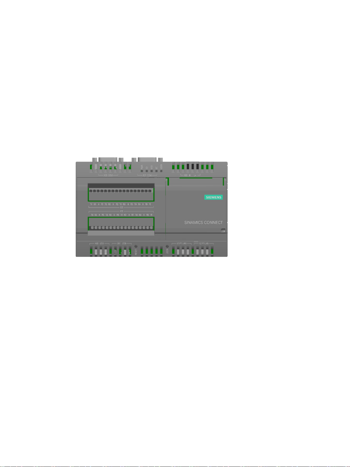
The SINAMICS CONNECT is designed to acquire data through the serial port on the
converter and synchronize the data to MindSphere, the Siemens Industrial IoT operating
system.
The SINAMICS CONNECT can be used to connect the following converters to MindSphere:
● SINAMICS V20
● SINAMICS G120 series (G120D excluded)
● MICROMASTER 440
● High degree of ruggedness
● Compact design
● RS232 and Ethernet interfaces
● Maintenance-free operation possible
The SINAMICS CONNECT is available with the following features:
● Intel Quark X1020 processor
● 1 GB RAM
● 2 x Ethernet interfaces
● 8 x RS232 ports
SINAMICS CONNECT
18 Operating Instructions, 10/2018, A5E45421408
Overview
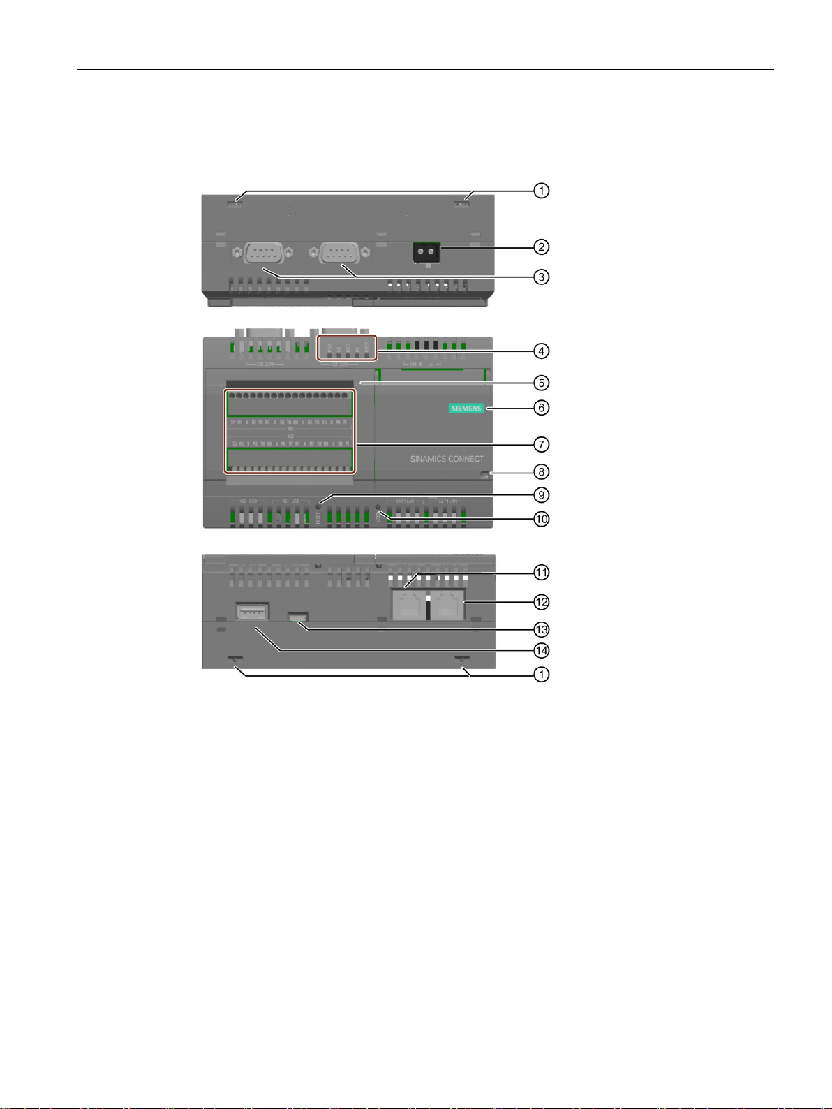
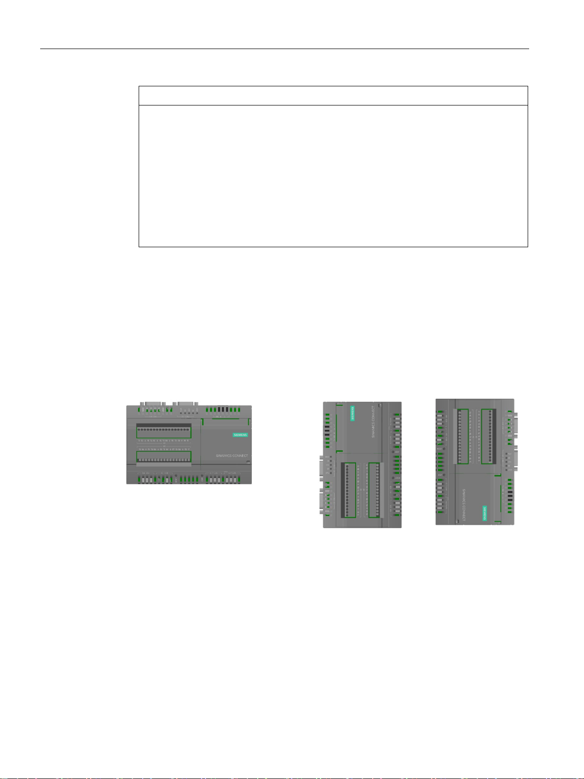
2.2
Structure of the device
Top view
Front view
Bottom view
①
Openings for push
mounting
⑧
Securing device
②
Power supply connector
⑨
RESET button for the CPU
③
COM interfaces (reserved)
⑩
USER button
④
LED display, see Section "
overview (Page 88)"
⑪
Ethernet interface 10/100
⑤
Cover on left
⑫ Ethernet interface 10/100
⑥
Cover on right
⑬
USB Type Micro B (reserved)
⑦
RS232 interface
⑭ USB Type A (reserved)
2.2 Structure of the device
SINAMICS CONNECT
Operating Instructions, 10/2018, A5E45421408
-in lugs for wall
Interface
Mbps
Mbps
19
Overview
2.3
Scope of delivery
Note
The device contains open
device.
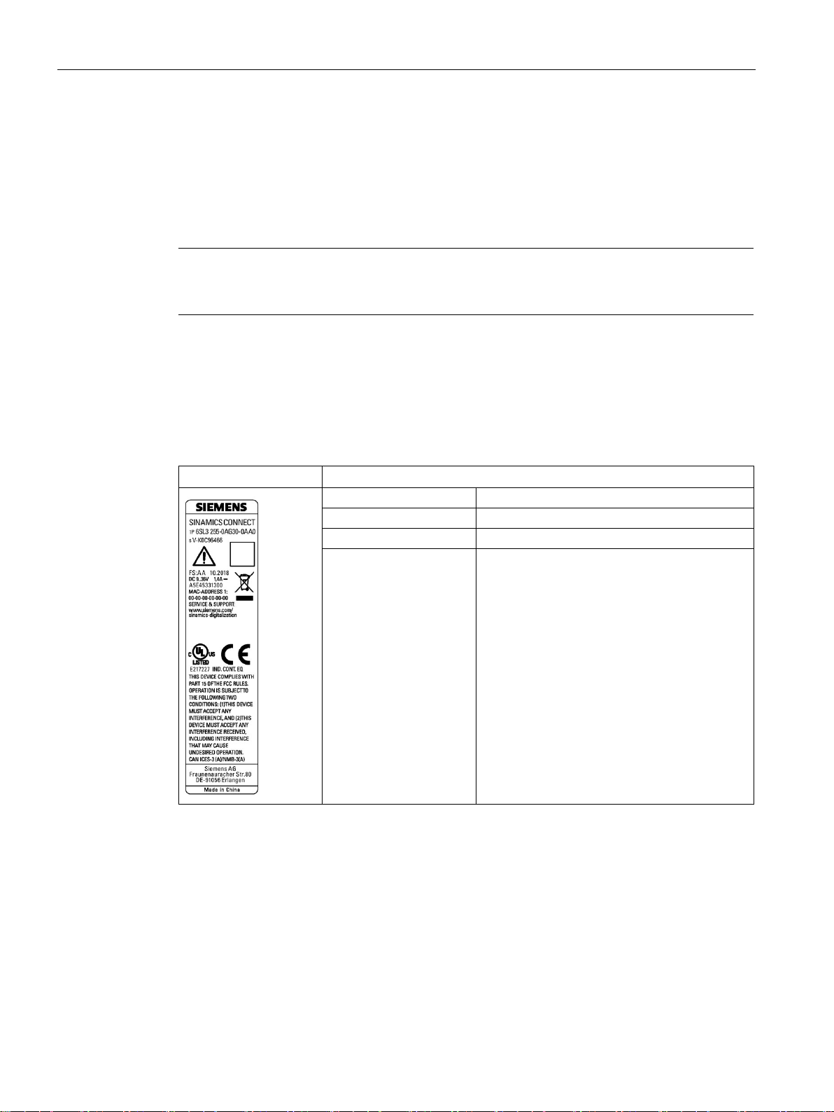
Identification data of the device
Example rating plate
Enter the identification data in the table below
Article number
6SL ...
Serial number
S V
Production version
FS
2.3 Scope of delivery
Check the scope of delivery for completeness and intactness:
● One SINAMICS CONNECT device with one DC terminal block mounted
● Quick Install Guide in English
-source software (OSS). The OSS license terms are saved in the
The device can be clearly identified with the help of this identification data in case of repairs
or theft.
You can find this information on the rating plate. The following illustration shows an example.
All existing Ethernet
addresses (MAC)
SINAMICS CONNECT
20 Operating Instructions, 10/2018, A5E45421408
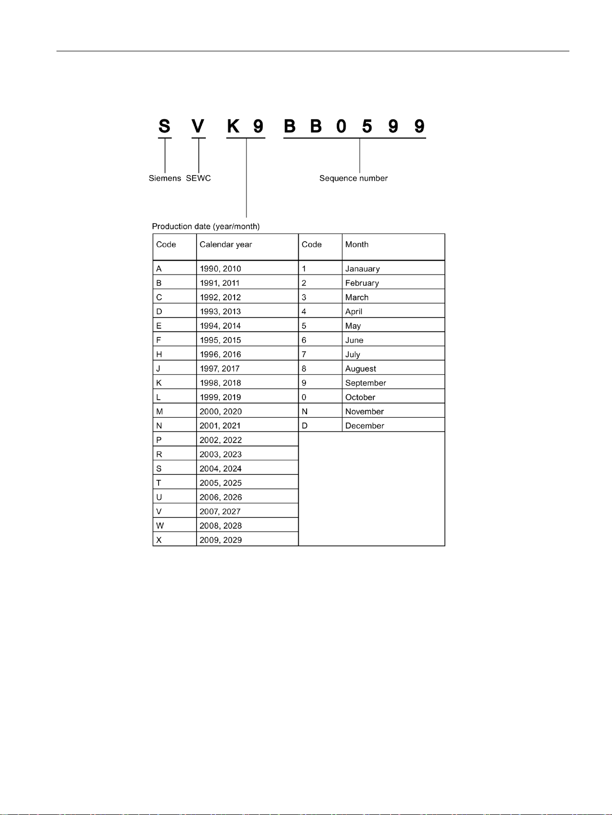
Overview
Serial number explanation (example)
2.3 Scope of delivery
SINAMICS CONNECT
Operating Instructions, 10/2018, A5E45421408
21

Overview
2.4
Accessories
Push-in lugs
2.4 Accessories
The following accessory is not included in the scope of delivery and can be ordered
separately.
Industry Mall (https://mall.industry.siemens.com)
Set with 100 push-in lugs for wall mounting
Article number: 3RB1900-0B
SINAMICS CONNECT
22 Operating Instructions, 10/2018, A5E45421408
3
3.1
Preparing for installation
3.1.1
Checking the delivery
Procedure
NOTICE
Damaged packaging of a device during transport and storage
WARNING
Electric shock and fire hazard due to damaged device
1. When accepting a delivery, please check the packaging for visible transport damage.
2. If any transport damage is present at the time of delivery, lodge a complaint at the
shipping company in charge. Have the shipper confirm the transport damage
immediately.
3. Unpack the device at its installation location.
4. Keep the original packaging in case you have to transport the unit again.
A damaged packaging indicates that ambient conditions have already had a massive
impact on the device. If a device is transported or stored without packaging, shocks,
vibrations, pressure and moisture may impact the unprotected unit. This may cause
damage to the device.
• Do not dispose the original packaging.
• Pack the device during transportation and storage.
5. Check the scope of delivery for completeness and intactness:
– One SINAMICS CONNECT device with one DC terminal block mounted
– Quick Install Guide in English
6. If the contents of the packaging are incomplete, damaged or do not match your order,
inform the responsible delivery service immediately.
A damaged device can be under hazardous voltage and trigger a fire in the machine or
plant. A damaged device has unpredictable properties and states. This may cause
death or serious injury.
• Make sure that the damaged device is not inadvertently installed and put into
operation.
• Label the damaged device and keep it locked away.
• Send off the device for immediate repair.
SINAMICS CONNECT
Operating Instructions, 10/2018, A5E45421408
23
Mounting
NOTICE
Damage from condensation
3.1.2
Permitted mounting orientation and mounting types
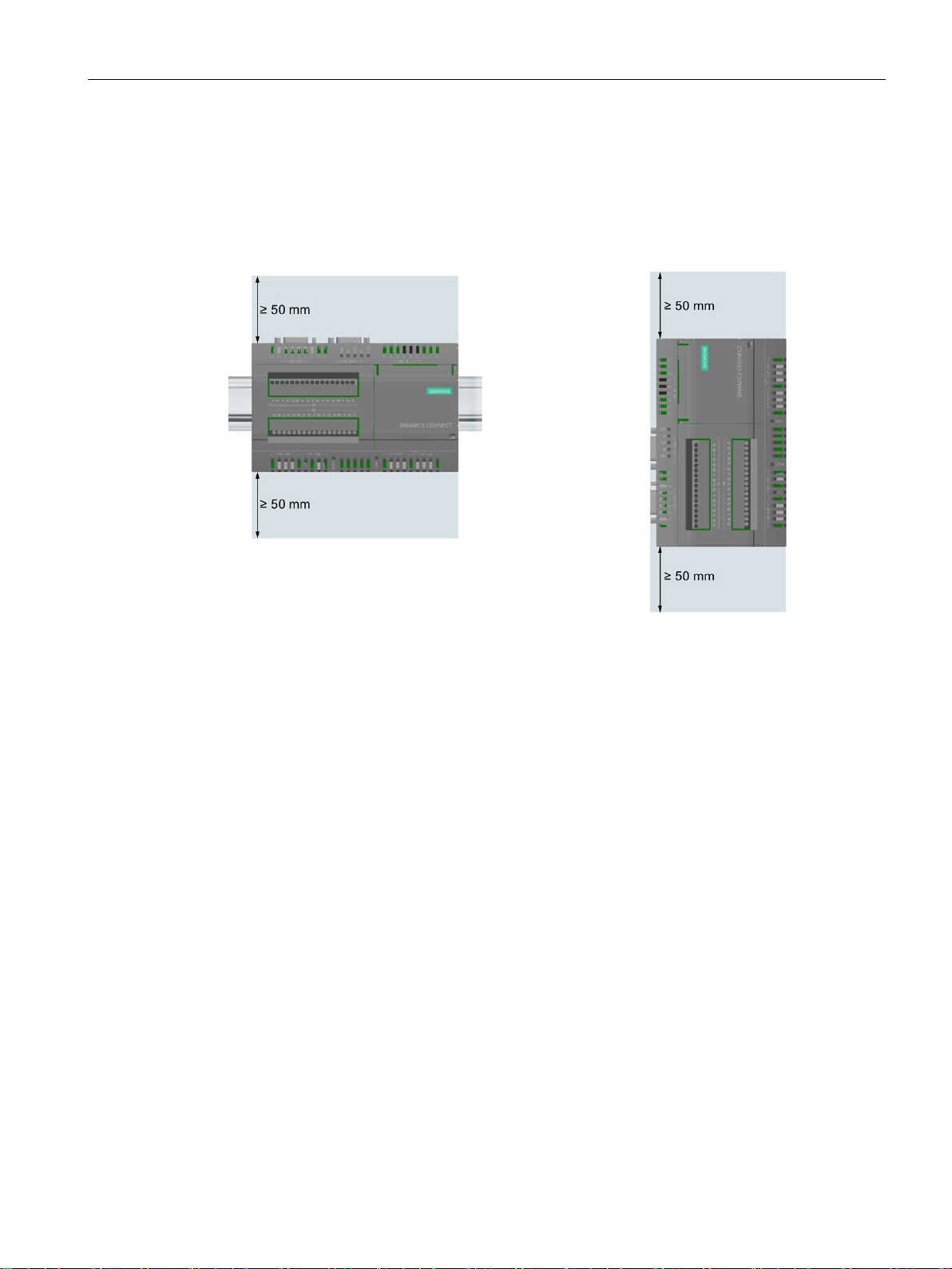
Horizontal mounting, preferred
Vertical mounting
3.1 Preparing for installation
If the device is subjected to low temperatures or extreme fluctuations in temperature
during transportation, for example in cold weather, moisture could build up on or inside
the HMI device (condensation). Moisture causes a short circuit in electrical circuits and
damages the device.
• Store the device in a dry place.
• Bring the device to room temperature before starting it up.
• Do not expose the device to direct heat radiation from a heating device.
• If condensation develops, wait approximately 12 hours or until the device is
completely dry before switching it on.
7. Please keep the enclosed documentation in a safe place. It belongs to the device. You
need the documentation when you commission the device for the first time.
8. Write down the identification data of the device.
The device can be attached horizontally or vertically on a DIN rail or to a wall.
Take into account the permitted temperature range for operation that depends on the
mounting position in accordance with Section "Ambient conditions (Page 86)".
SINAMICS CONNECT
24 Operating Instructions, 10/2018, A5E45421408
Mounting
Clearances
3.2
Mounting the device
Protection against the spread of fire
Protection against condensation or electrically conductive contamination
3.2 Mounting the device
Make sure that the following clearances to another component or to the wall of a housing are
complied with:
● Both above and below the device: ≥ 50 mm
The device may be operated only in closed housings or in control cabinets with protective
covers that are closed, and when all of the protective devices are used. The installation of
the device in a metal control cabinet or the protection with another equivalent measure must
prevent the spread of fire and emissions outside the control cabinet.
Protect the device, e.g. by installing it in a control cabinet with degree of protection IP54
according to IEC 60529 or NEMA 12. Further measures may be necessary for particularly
critical operating conditions.
If condensation or conductive pollution can be excluded at the installation site, a lower
degree of control cabinet protection may be permitted.
SINAMICS CONNECT
Operating Instructions, 10/2018, A5E45421408
25

Mounting
3.2.1
Mounting instructions
Fasten securely
NOTICE
Equipment falling due to insufficient load carrying capacity
NOTICE
Equipment falling due to incorrect fixing elements
Material
Bore diameter
Fixing element
3.2 Mounting the device
Note the following:
● The device is approved for indoor operation only.
● For installation in a cabinet, observe the relevant DIN/VDE requirements or the applicable
country-specific regulations.
● When the device is used in the area of Industrial Control Equipment in accordance with
UL61010-2-201, note that the device is classified as "Open Type". A UL61010-2-201
conform enclosure is therefore a mandatory requirement for approval or operation
according to UL61010-2-201.
● To protect the enclosure of the device against unauthorized opening, after installing the
expansions you can screw the rear panel of the enclosure to the front panel of the
enclosure using two screws. The screws are not included in the scope of delivery. Use
only screws of the type WN1452-K30x20-ST-A2F and tighten the screws using a torque
of 0.5 Nm.
● The device is designed for operation in the second environment (industrial area) and may
not be used in the first environment (residential area) unless the appropriate noise
suppression measures have been adopted.
If the mounting surface for wall mounting does not have a sufficient load-bearing capacity,
the device may fall and be damaged.
• Ensure that the mounting surface on the wall can bear four times the total weight of the
device, including fixing elements.
If you use anchors and screws other than those specified below for wall mounting, safe
mounting is not guaranteed. The device can fall and may be damaged.
• Use only the anchors and screws specified in the following table.
Concrete Select according to the specification
of the mounting elements used
Plasterboard,
(at least 13 mm thick)
Metal,
(at least 2 mm thick)
• Anchor, ∅ 6 mm, 40 mm long
• Screw, ∅ 4-5 mm, 40 mm long
• Toggle plug, ∅ 12 mm, 50 mm
long
• M4 screw × 15
• M4 nut
SINAMICS CONNECT
26 Operating Instructions, 10/2018, A5E45421408
Mounting
3.2.2
Mounting on DIN rails
Requirement
Procedure
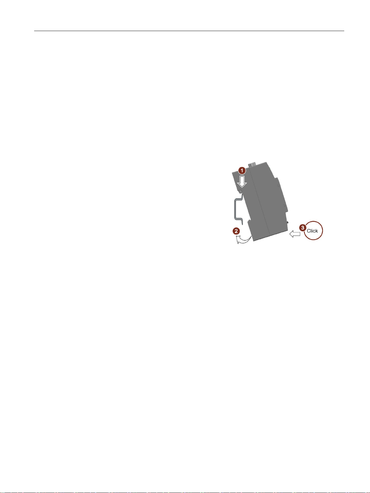
Mounting
1.
2.
3.
Removing
3.2.3
Wall mounting
Requirement
3.2 Mounting the device
● A DIN rail, 35 mm standard profile
The DIN rail is installed at the installation site.
Place the device and rail clip on the
upper edge of the standard profile rail at
the position shown and push the device
down.
Swing the rail clips of the device from
below via the standard profile rail.
Push the device in the direction of the
standard profile rail. You will hear the
device click into place.
1. Push down the device until it is released by the rail clips.
2. Swing the device out of the standard profile rail.
3. Lift the device up and off.
The device is suitable for horizontal or vertical wall mounting.
● Four push-in lugs.
The push-in lugs must be ordered separately, see Section "Accessories (Page 22)".
● Four anchors and four screws.
SINAMICS CONNECT
Operating Instructions, 10/2018, A5E45421408
27
Mounting
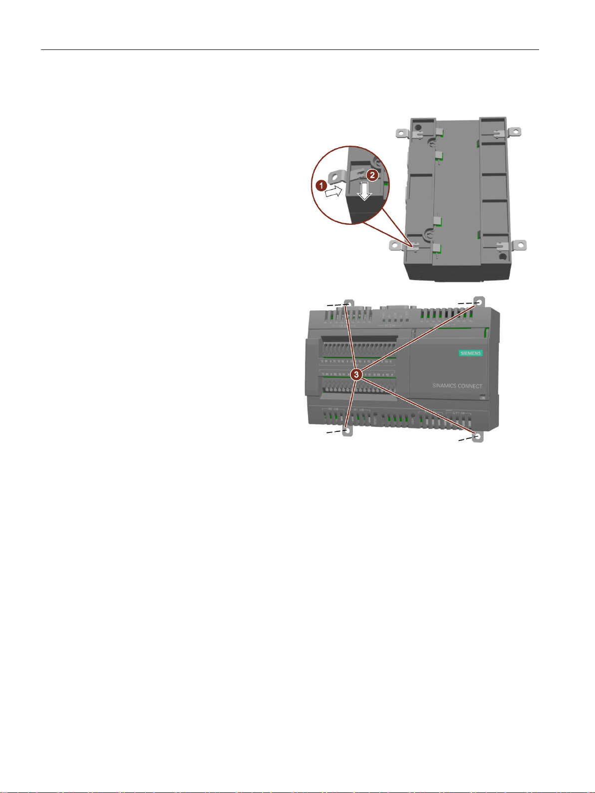
Procedure
1.
2.
3.
required holes in the wall and fasten
3.2 Mounting the device
Guide a push-in lug through the
corresponding opening at the top of
the device, as shown in the figure.
Press the push-in lug down.
Mark the bore holes, drill the
the device to the wall using four
screws and corresponding anchors.
SINAMICS CONNECT
28 Operating Instructions, 10/2018, A5E45421408
 Loading...