

Siemens SINAMIC G130 Operating Instructions Manual


___________________
___________________
___________________
___________________
___________________
___________________
SINAMICS
SINAMICS G130
Braking Module / braking resistor
Operating Instructions
Firmware version V5.1
11/2017
A5E00331454A
Safety information
1
General
2
Mechanical installation
3
Connection
4
Maintenance and servicing
5
Technical specifications
6
Siemens AG
Division Process Industries and Drives
Postfach 48 48
90026 NÜRNBERG
GERMANY
A5E00331454A
Ⓟ
Copyright © Siemens AG 2004 - 2017.
All rights reserved
Legal information
Warning notice system
DANGER
indicates that death or severe personal injury will result if proper precautions are not taken.
WARNING
indicates that death or severe personal injury may result if proper precautions are not taken.
CAUTION
indicates that minor personal injury can result if proper precautions are not taken.
NOTICE
indicates that property damage can result if proper precautions are not taken.
Qualified Personnel
personnel qualified
Proper use of Siemens products
WARNING
Siemens products may only be used for the applications described in the catalog and in the relevant technical
ambient conditions must be complied with. The information in the relevant documentation must be observed.
Trademarks
Disclaimer of Liability
This manual contains notices you have to observe in order to ensure your personal safety, as well as to prevent
damage to property. The notices referring to your personal safety are highlighted in the manual by a safety alert
symbol, notices referring only to property damage have no safety alert symbol. These notices shown below are
graded according to the degree of danger.
If more than one degree of danger is present, the warning notice representing the highest degree of danger will
be used. A notice warning of injury to persons with a safety alert symbol may also include a warning relating to
property damage.
The product/system described in this documentation may be operated only by
task in accordance with the relevant documentation, in particular its warning notices and safety instructions.
Qualified personnel are those who, based on their training and experience, are capable of identifying risks and
avoiding potential hazards when working with these products/systems.
Note the following:
documentation. If products and components from other manufacturers are used, these must be recommended
or approved by Siemens. Proper transport, storage, installation, assembly, commissioning, operation and
maintenance are required to ensure that the products operate safely and without any problems. The permissible
All names identified by ® are registered trademarks of Siemens AG. The remaining trademarks in this publication
may be trademarks whose use by third parties for their own purposes could violate the rights of the owner.
We have reviewed the contents of this publication to ensure consistency with the hardware and software
described. Since variance cannot be precluded entirely, we cannot guarantee full consistency. However, the
information in this publication is reviewed regularly and any necessary corrections are included in subsequent
editions.
for the specific
03/2018 Subject to change

Table of contents
1 Safety information ................................................................................................................................... 5
2 General ................................................................................................................................................. 11
3 Mechanical installation .......................................................................................................................... 15
4 Connection ........................................................................................................................................... 29
5 Maintenance and servicing .................................................................................................................... 37
6 Technical specifications ........................................................................................................................ 39
1.1 General safety instructions ....................................................................................................... 5
1.2 Handling electrostatic sensitive devices (ESD) ...................................................................... 10
2.1 Braking Module ....................................................................................................................... 12
2.2 Braking resistor ....................................................................................................................... 14
3.1 General ................................................................................................................................... 15
3.2 Braking Modules: overview ..................................................................................................... 16
3.3 Installing the Braking Module .................................................................................................. 19
3.3.1 Installing the Braking Module in a Power Module, frame size FX .......................................... 19
3.3.2 Installing the Braking Module in a Power Module frame size GX ........................................... 22
3.3.3 Installing the Braking Module in a Power Module frame size HX ........................................... 25
3.3.4 Installing the Braking Module in a Power Module frame size JX ............................................ 26
3.4 Installing the braking resistor .................................................................................................. 27
4.1 Cable lugs ............................................................................................................................... 29
4.2 Connecting the Braking Module .............................................................................................. 30
4.3 Connecting the braking resistor .............................................................................................. 34
4.4 Disabling the Vdc-max controller ............................................................................................ 36
Braking Module / braking resistor
Operating Instructions, 11/2017, A5E00331454A
3

Table of contents
Braking Module / braking resistor
4 Operating Instructions, 11/2017, A5E00331454A
1
1.1
General safety instructions
WARNING
Electric shock and danger to life due to other energy sources
WARNING
Electric shock due to connection to an unsuitable power supply
Touching live components can result in death or serious injury.
• Only work on electrical equipment if you are appropriately qualified.
• Always observe the country-specific safety rules for all work.
Generally, the following steps apply when establishing safety:
1. Prepare for disconnection. Notify all those who will be affected by the procedure.
2. Isolate the drive system from the power supply and take measures to prevent it being
switched back on again.
3. Wait until the discharge time specified on the warning labels has elapsed.
4. Check that there is no voltage between any of the power connections, and between any
of the power connections and the protective conductor connection.
5. Check that every auxiliary circuit is de-energized.
6. Ensure that the motors cannot move.
7. Identify all other dangerous energy sources, e.g. compressed air, hydraulic systems or
water. Switch the energy sources to a safe state.
8. Check that the correct drive system is completely locked.
After you have completed the work, restore the operational readiness by following the
above steps in the reverse order.
Braking Module / braking resistor
Operating Instructions, 11/2017, A5E00331454A
When equipment is connected to an unsuitable power supply, exposed components may
carry a hazardous voltage that might result in serious injury or death.
• Only use power supplies that provide SELV (Safety Extra Low Voltage) or PELV
(Protective Extra Low Voltage) output voltages for all connections and terminals of the
electronics modules.
5
Safety information
WARNING
Electric shock due to equipment damage
WARNING
Electric shock due to unconnected cable shield
WARNING
Electric shock if there is no ground connection
WARNING
Arcing when a plug connection is opened during operation
NOTICE
Property damage due to loose power connections
1.1 General safety instructions
Improper handling may cause damage to equipment. For damaged devices, hazardous
voltages can be present at the enclosure or at exposed components; if touched, this can
result in death or severe injury.
• Ensure compliance with the limit values specified in the technical data during transport,
storage and operation.
• Do not use any damaged devices.
Hazardous touch voltages can occur through capacitive cross-coupling due to unconnected
cable shields.
• Connect cable shields and unused conductors of power cables (e.g. brake conductors)
at least on one side to the grounded housing potential.
For missing or incorrectly implemented protective conductor connection for devices with
protection class I, high voltages can be present at open, exposed parts, which when
touched, can result in death or severe injury.
• Ground the device in compliance with the applicable regulations.
Opening a plug connection when a system is in operation can result in arcing that may
cause serious injury or death.
• Only open plug connections when the equipment is in a voltage-free state, unless it has
been explicitly stated that they can be opened in operation.
Insufficient tightening torques or vibration can result in loose power connections. This can
result in damage due to fire, device defects or malfunctions.
• Tighten all power connections to the prescribed torque.
• Check all power connections at regular intervals, particularly after equipment has been
transported.
Braking Module / braking resistor
6 Operating Instructions, 11/2017, A5E00331454A
Safety information
WARNING
Spread of fire from built-in devices
WARNING
Failure of pacemakers or implant malfunctions due to electromagnetic fields
WARNING
Unexpected movement of machines caused by radio devices or mobile phones
WARNING
Motor fire in the event of insulation overload
1.1 General safety instructions
In the event of fire outbreak, the enclosures of built-in devices cannot prevent the escape of
fire and smoke. This can result in serious personal injury or property damage.
• Install built-in units in a suitable metal cabinet in such a way that personnel are
protected against fire and smoke, or take other appropriate measures to protect
personnel.
• Ensure that smoke can only escape via controlled and monitored paths.
Electromagnetic fields (EMF) are generated by the operation of electrical power equipment,
such as transformers, converters, or motors. People with pacemakers or implants in the
immediate vicinity of this equipment are at particular risk.
• If you have a heart pacemaker or implant, maintain a minimum distance of 2 m from
electrical power equipment.
When radio devices or mobile phones with a transmission power > 1 W are used in the
immediate vicinity of components, they may cause the equipment to malfunction.
Malfunctions may impair the functional safety of machines and can therefore put people in
danger or lead to property damage.
• If you come closer than around 2 m to such components, switch off any radio devices or
mobile phones.
• Use the "SIEMENS Industry Online Support App" only on equipment that has already
been switched off.
There is a greater load on the motor insulation as result of a ground fault in an IT system. If
the insulation fails, it is possible that death or severe injury can occur as a result of smoke
and fire.
• Use a monitoring device that signals an insulation fault.
• Correct the fault as quickly as possible so the motor insulation is not overloaded.
Braking Module / braking resistor
Operating Instructions, 11/2017, A5E00331454A
7
Safety information
WARNING
Fire due to inadequate ventilation clearances
WARNING
Unrecognized dangers due to missing or illegible warning labels
NOTICE
Device damage caused by incorrect voltage/insulation tests
WARNING
Unexpected movement of machines caused by inactive safety functions
1.1 General safety instructions
Inadequate ventilation clearances can cause overheating of components with subsequent
fire and smoke. This can cause severe injury or even death. This can also result in
increased downtime and reduced service lives for devices/systems.
• Ensure compliance with the specified minimum clearance as ventilation clearance for
the respective component.
Dangers might not be recognized if warning labels are missing or illegible. Unrecognized
dangers may cause accidents resulting in serious injury or death.
• Check that the warning labels are complete based on the documentation.
• Attach any missing warning labels to the components, where necessary in the national
language.
• Replace illegible warning labels.
Incorrect voltage/insulation tests can damage the device.
• Before carrying out a voltage/insulation check of the system/machine, disconnect the
devices as all converters and motors have been subject to a high-voltage test by the
manufacturer, and therefore it is not necessary to perform an additional test within the
system/machine.
Inactive or non-adapted safety functions can trigger unexpected machine movements that
may result in serious injury or death.
• Observe the information in the appropriate product documentation before
commissioning.
• Carry out a safety inspection for functions relevant to safety on the entire system,
including all safety-related components.
• Ensure that the safety functions used in your drives and automation tasks are adjusted
and activated through appropriate parameterizing.
• Perform a function test.
• Only put your plant into live operation once you have absolutely guaranteed that the
functions relevant to safety are operating correctly.
Braking Module / braking resistor
8 Operating Instructions, 11/2017, A5E00331454A

Safety information
Note
Important safety instructions for Safety Integrated functions
If you want to use Safety Integrated functions, you must observe the safety instructions in
the Safety Integrated manuals.
1.1 General safety instructions
Braking Module / braking resistor
Operating Instructions, 11/2017, A5E00331454A
9
Safety information
1.2
Handling electrostatic sensitive devices (ESD)
NOTICE
Damage through electric fields or electrostatic discharge
1.2 Handling electrostatic sensitive devices (ESD)
Electrostatic sensitive devices (ESD) are individual components, integrated circuits, modules
or devices that may be damaged by either electric fields or electrostatic discharge.
Electric fields or electrostatic discharge can cause malfunctions through damaged
individual components, integrated circuits, modules or devices.
• Only pack, store, transport and send electronic components, modules or devices in their
original packaging or in other suitable materials, e.g. conductive foam rubber or
aluminum foil.
• Only touch components, modules and devices when you are grounded by one of the
following methods:
– Wearing an ESD wrist strap
– Wearing ESD shoes or ESD grounding straps in ESD areas with conductive flooring
• Only place electronic components, modules or devices on conductive surfaces (table
with ESD surface, conductive ESD foam, ESD packaging, ESD transport container).
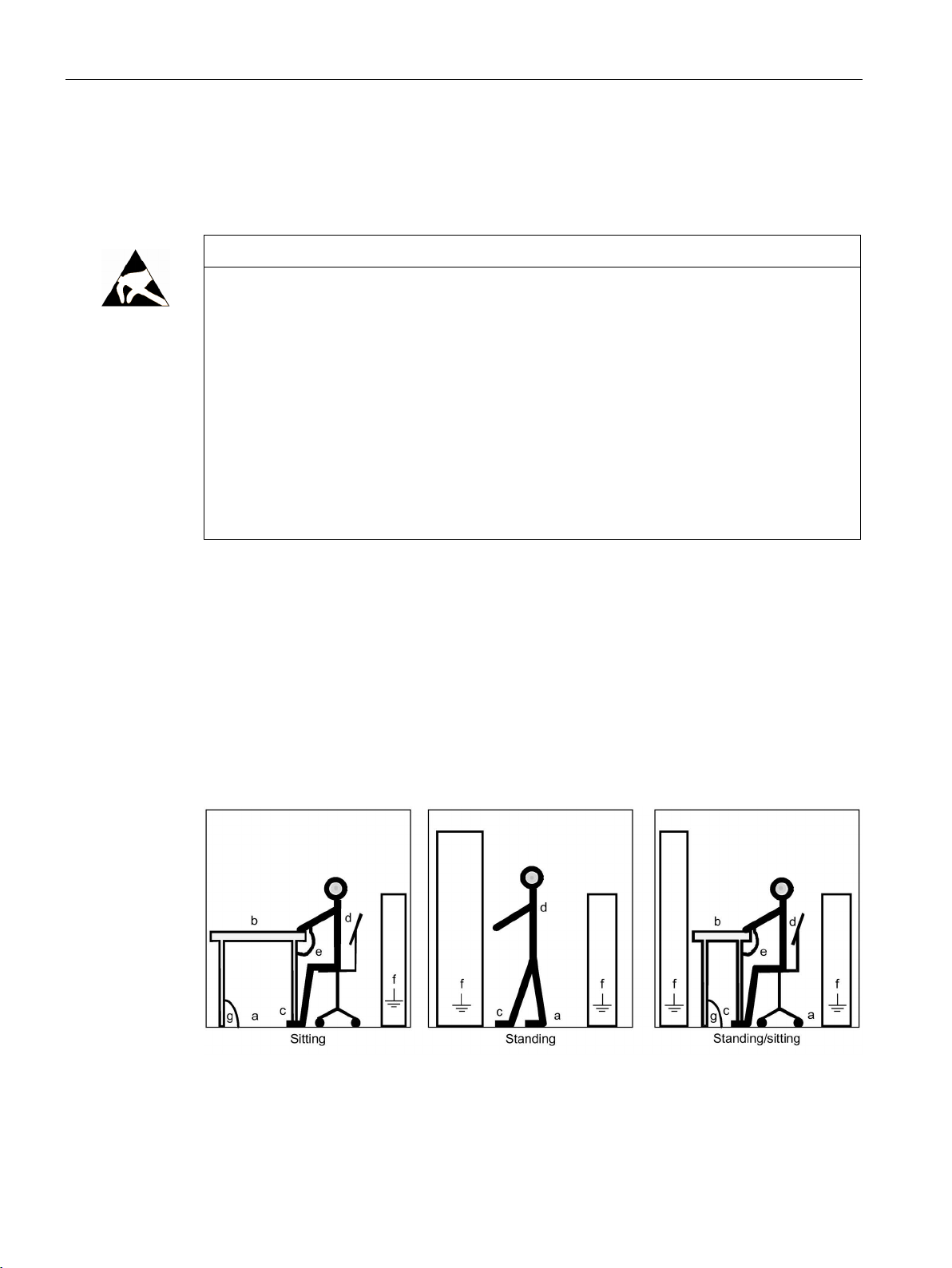
The necessary ESD protective measures are clearly illustrated in the following diagram:
● a = conductive floor surface
● b = ESD table
● c = ESD shoes
● d = ESD overall
● e = ESD wristband
● f = cabinet ground connection
● g = contact with conductive flooring
Figure 1-1 ESD protective measures
Braking Module / braking resistor
10 Operating Instructions, 11/2017, A5E00331454A
2
WARNING
Non-observance of the fundamental safety instructions and residual risks
WARNING
Fire and device damage as a result of ground fault/short-circuit
– Lay the cables in separate cable ducts or conduits.
WARNING
Fire due to overheating when the total length of the connecting cables is exceeded
WARNING
Fire through overheating due to insufficient ventilation clearances
The non-observance of the fundamental safety instructions and residual risks stated in
Chapter 1 can result in accidents with severe injuries or death.
• Adhere to the fundamental safety instructions.
• When assessing the risk, take into account residual risks.
Inadequate installation of the cables to the braking resistor can result in a ground
fault/short-circuit and place persons at risk as a result of the associated smoke and fire.
• Comply with local installation regulations that enable this fault to be ruled out.
• Protect the cables from mechanical damage.
• In addition, apply one of the following measures:
– Use cables with double insulation.
– Maintain adequate clearance, e.g. by using spacers.
Excessively long Braking Module connection cables can cause components to overheat
with the associated risk of fire and smoke.
• The Braking Module connecting cables may not be longer than 100 m.
Inadequate ventilation clearances can cause overheating with a risk for personnel through
smoke development and fire. This can also result in increased failures and reduced service
lives of braking resistors.
• It is essential that you maintain a ventilation clearance of 200 mm on all sides of the
component with ventilation grilles.
Braking Module / braking resistor
Operating Instructions, 11/2017, A5E00331454A
11

General
NOTICE
Material damage due to loose power connections
NOTICE
Damage through the use of non-released braking resistors
2.1
Braking Module
Description
Structure
2.1 Braking Module
Insufficient tightening torques or vibration can result in faulty electrical connections. This
can cause fire damage or malfunctions.
• Tighten all power connections with the specified tightening torques, e.g. line supply
connection, motor connection, DC-link connections.
• Check the tightening torques of all power connections at regular intervals and tighten
them when required. This applies in particular after transport.
Braking resistors can be damaged when using braking resistors other than those specified
in this manual.
• Only use braking resistors released by Siemens.
A Braking Module (and an external braking resistor) is required in certain cases when the
drive is to be braked or brought to a standstill (e.g. EMERGENCY STOP category 1). The
Braking Module contains the power electronics and the associated Control Unit. The supply
voltage for the electronics is drawn from the DC link.
During operation, the DC-link energy is converted to heat loss in an external braking resistor.
The Braking Module functions independently of the converter closed-loop controller. In the
case of Power Modules with frame sizes HX and JX, it is possible to operate several Braking
Modules in parallel in order to enhance performance. In this case, each Braking Module
must be fitted with its own braking resistor.
The Braking Module is inserted in a slot inside the Power Module, the fan of which ensures
forced cooling. The Braking Module is connected to the DC link by means of the busbar sets
and flexible cables, which are supplied as standard.
Braking Module / braking resistor
12 Operating Instructions, 11/2017, A5E00331454A

General
Assignment of Braking Module and Power Module
Power Module
Unit rating of the
Power Module
Suitable Braking Module
Rated power output of the Braking
Module
Suitable brake resistance
Line voltage 3-phase 380 – 480 VAC
6SL3310-1GE32-6AA3
132 kW
6SL3300-1AE31-3AA0
25 kW
6SL3000-1BE31-3AA0
6SL3310-1GE33-8AA3
200 kW
6SL3300-1AE32-5AA0
50 kW
6SL3000-1BE32-5AA0
6SL3310-1GE35-0AA3
250 kW
6SL3300-1AE32-5AA0
50 kW
6SL3000-1BE32-5AA0
6SL3310-1GE36-1AA3
315 kW
6SL3300-1AE32-5BA0
50 kW
6SL3000-1BE32-5AA0
6SL3310-1GE37-5AA3
400 kW
6SL3300-1AE32-5BA0
50 kW
6SL3000-1BE32-5AA0
6SL3310-1GE38-4AA3
450 kW
6SL3300-1AE32-5BA0
50 kW
6SL3000-1BE32-5AA0
6SL3310-1GE41-0AA3
560 kW
6SL3300-1AE32-5BA0
50 kW
6SL3000-1BE32-5AA0
Line voltage 3-phase 500 – 600 VAC
6SL3310-1GF31-8AA3
110 kW
6SL3300-1AF32-5AA0
50 kW
6SL3000-1BF32-5AA0
6SL3310-1GF32-2AA3
132 kW
6SL3300-1AF32-5AA0
50 kW
6SL3000-1BF32-5AA0
6SL3310-1GF32-6AA3
160 kW
6SL3300-1AF32-5AA0
50 kW
6SL3000-1BF32-5AA0
6SL3310-1GF33-3AA3
200 kW
6SL3300-1AF32-5AA0
50 kW
6SL3000-1BF32-5AA0
6SL3310-1GF34-1AA3
250 kW
6SL3300-1AF32-5BA0
50 kW
6SL3000-1BF32-5AA0
6SL3310-1GF34-7AA3
315 kW
6SL3300-1AF32-5BA0
50 kW
6SL3000-1BF32-5AA0
6SL3310-1GF35-8AA3
400 kW
6SL3300-1AF32-5BA0
50 kW
6SL3000-1BF32-5AA0
6SL3310-1GF37-4AA3
450 kW
6SL3300-1AF32-5BA0
50 kW
6SL3000-1BF32-5AA0
6SL3310-1GF38-1AA3
560 kW
6SL3300-1AF32-5BA0
50 kW
6SL3000-1BF32-5AA0
Line voltage 3-phase 660 – 690 VAC
6SL3310-1GH28-5AA3
75 kW
6SL3300-1AH31-3AA0
25 kW
6SL3000-1BH31-3AA0
6SL3310-1GH31-0AA3
90 kW
6SL3300-1AH31-3AA0
25 kW
6SL3000-1BH31-3AA0
6SL3310-1GH31-2AA3
110 kW
6SL3300-1AH31-3AA0
25 kW
6SL3000-1BH31-3AA0
6SL3310-1GH31-5AA3
132 kW
6SL3300-1AH31-3AA0
25 kW
6SL3000-1BH31-3AA0
6SL3310-1GH31-8AA3
160 kW
6SL3300-1AH32-5AA0
50 kW
6SL3000-1BH32-5AA0
6SL3310-1GH32-6AA3
250 kW
6SL3300-1AH32-5AA0
50 kW
6SL3000-1BH32-5AA0
6SL3310-1GH33-3AA3
315 kW
6SL3300-1AH32-5AA0
50 kW
6SL3000-1BH32-5AA0
6SL3310-1GH34-1AA3
400 kW
6SL3300-1AH32-5BA0
50 kW
6SL3000-1BH32-5AA0
6SL3310-1GH34-7AA3
450 kW
6SL3300-1AH32-5BA0
50 kW
6SL3000-1BH32-5AA0
6SL3310-1GH35-8AA3
560 kW
6SL3300-1AH32-5BA0
50 kW
6SL3000-1BH32-5AA0
6SL3310-1GH37-4AA3
710 kW
6SL3300-1AH32-5BA0
50 kW
6SL3000-1BH32-5AA0
6SL3310-1GH38-1AA3
800 kW
6SL3300-1AH32-5BA0
50 kW
6SL3000-1BH32-5AA0
2.1 Braking Module
Table 2- 1 Assignment of Braking Module and Power Module
6SL3310-1GE32-1AA3 110 kW 6SL3300-1AE31-3AA0 25 kW 6SL3000-1BE31-3AA0
6SL3310-1GE33-1AA3 160 kW 6SL3300-1AE32-5AA0 50 kW 6SL3000-1BE32-5AA0
6SL3310-1GH32-2AA3 200 kW 6SL3300-1AH32-5AA0 50 kW 6SL3000-1BH32-5AA0
Braking Module / braking resistor
Operating Instructions, 11/2017, A5E00331454A
13
 Loading...