

Page 1
SINACON PV
Photovoltaic Central Inverter
Technical data 01 / 2020
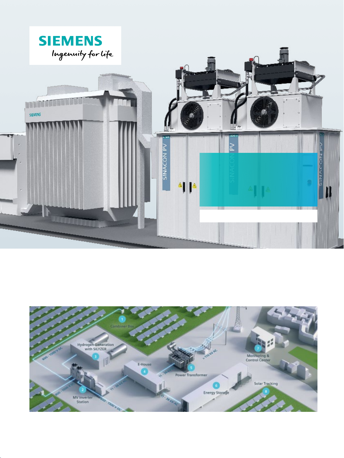
The SINACON PV inverter is used in medium and large utilityscale photovoltaic power plants to achieve high efficiency.
It is equipped with 3-level IGBT modules for input voltages
of up to DC 1,500 V to maximize energy efficiency. The
integrated DC and AC distribution makes the SINACON PV
inverter cost efficient. Standardized interfaces for easy plug
and play reduce engineering hours.
The SINACON PV inverter is part of the MV-Inverter Station with the transformer and RMU (Ring Main Unit)
in the eBoP solution (electrical Balance of Plant).
• Designed for harsh environments
• IP65 without humidity limits
• Liquid cooling (-40 °C … +60 °C possible)
• Late power derating over 40 °C
• Extreme high quality standards
1
Page 2
SINACON PV series | Technical data
Storage, transportation and operation
Temperature -40 °C … +60 °C
Relative humidity 0% … 100%
Maximum altitude of installation site without derating < 1,500 m above MSL
Cooling
Cooling method Forced cooling by means of fans and liquid cooling
Applicable standards and conformity
BDEW (Germany) BDEW Guideline, FGW TG3, TG4 and TG8
IEC 61683 (efficiency) IEC 61683: 1999
IEC 62116 (anti islanding) IEC 62116: 2014 (at 50 Hz)
EMC Emission IEC 61000-6-4: 2007 + A1: 2011
EMC Immunity IEC 61000-6-2: 2005
Electrical Safety IEC 62109-1: 2010, IEC 62109-2: 2011, IP65 according to IEC 60529: 1989
Degree of protection: IP65 (cabinet only) IEC 60529
General data
Control strategy MPPT
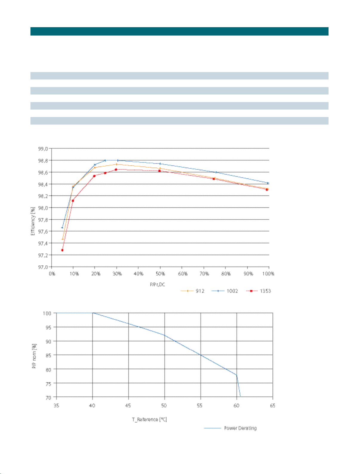
Efficiency (PV 5000) (97.6|98.5|98.9|98.9|99.0|98.9|98.8|98.7)% For (5|10|20|25|30|50|75|100)% power at
1,006 V
without self-consumption for cooling
DC
EU and CEC efficiency 98.8% Without internal consumption
Infeed starts from 260 W … 2,500 W Depending on cooling
Standby loss 80 W … 150 W –
Max. self-consumption for cooling 5,000 W Without cabinet heating
Mechanical data
Mounting position Vertical –
Type of mounting Floor mounting –
Number of Power Units 1 2 3 4
SINACON PV series PV1000 … PV1250 PV2000 … PV2500 PV3000 … PV3750 PV4000 … PV5000
Dimensions (without pallet, with heat
exchanger); (W x H x D)
1)
Weight
2,120 x 3,760 x 1,170 mm 3,690 x 3,760 x 1,170 mm
< 1,600 kg < 2,200 kg < 3,300 kg < 3,900 kg
Color RAL 7035
Input data (DC)
Independent inputs 1 … 2 Depending on configuration
Nominal voltage min. MPP voltage –
DC voltage (max. MPP) 1,500 V Depending on application
DC voltage (min. MPP) 802 V / 882 V (AC 550 V)
For 100 % / 110 % nominal grid voltage
838 V / 922 V (AC 575 V)
875 V / 962 V (AC 600 V)
919 V / 1,010 V (AC 630 V)
962 V / 1,058 V (AC 660 V)
1,006 V / 1,107 V (AC 690 V)
DC current (max.) 1 … 4 x 1,200 A –
Short-circuit current (max.) 6,4 kA / 7 kA 250 A /315 A DC fuses
Nominal power 1 … 4 x 1,016 kW
–
1 … 4 x 1,062 kW
1 … 4 x 1,108 kW
1 … 4 x 1,159 kW
1 … 4 x 1,209 kW
1 … 4 x 1,270 kW
Capacitance to ground (max.) 2,000 μF Per IT system
1)
The weight refers to a complete system without extra options.
2
Page 3
Technical data | SINACON PV series
Output data (AC)
Apparent power (max.) and nominal power PV1000 … PV4000 kVA (AC 550 V)
With nominal grid voltage, cos φ = 1
PV1045 … PV4180 kVA (AC 575 V)
PV1090 … PV4360 kVA (AC 600 V)
PV1140 … PV4560 kVA (AC 630 V)
PV1200 … PV4800 kVA (AC 660 V)
PV1250 … PV5000 kVA (AC 690 V)
Number of independent systems 1 … 2 –
Grid voltage 550 … 690 V (±10% at U
) –
n (AC)
Nominal frequency 50 Hz / 60 Hz (±10%) –
Output current (max.) 1 … 4 x 1,050 A –
Short-circuit current (max.) 50 kA –
Power factor cos φ – Adjustable to local requirements
Harmonic distortion < 3% –
2)
Measured values
without internal consumption for AC 600 V (PV4360)
Derating
2)
Messured by Fraunhofer ISE
3
Page 4
SINACON PV series | Technical data
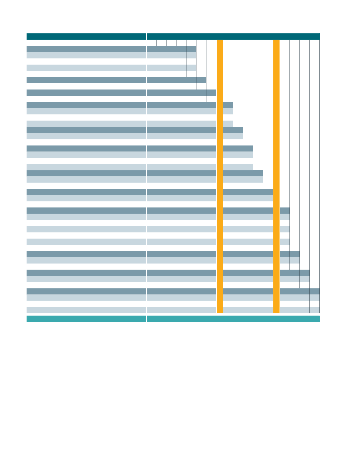
Order information – The order number consists of several digits depending on the configuration.
Description 1. 2. 3. 4. 5. 6. 7. – 8. 9. 10. 11. 12. – 13. 14. 15. 16.
SINACON PV inverter for medium voltage supply 6 S P 1
Number of power units
• 1 power unit 1
• 2 power units 2
• 3 power units 3
• 4 power units 4
Input connections (per power unit on plus and minus)
• 7 x M10 bolt and nut 0
Initial current measurement at DC input
• Each + input measured 1
Minimum operating ambient temperature
• Up to -10 °C 0
• Up to -25 °C, with cabinet heating 1
• Up to -40 °C, with cabinet heating and insulation 2
Applied standards
• IEC with external AC connection E
• UL with external AC connection U
Network- / optical fiber switch connection
• Singlemode unmanaged S
• Multimode unmanaged M
• RJ45 R
Seismic design
• Without seismic design 0
• With seismic design 1
Frequency
• 50 Hz 5
• 60 Hz 6
Inverter output AC voltage
• 550 V (PV1000 … PV4000) 4
• 575 V (PV1045 … PV4180) 5
• 600 V (PV1090 … PV4360) 6
• 630 V (PV1140 … PV4560) 7
• 660 V (PV1200 … PV4800) 8
• 690 V (PV1250 … PV5000) 9
Grounding / Insulation monitoring
• Insulation monitoring internal I
• Negative-pole grounding without isolation monitoring N
Inverter options
• None N
• AC precharge A
Additional internal transformer
• 63 A fuse 2
• Transformer with 8 kVA, AC 400 V 3
• none 9
Example: 6 S P 1 4 0 1 – 0 E S 0 5 – 6 N N 3
Published by
Siemens AG
Smart Infrastructure
Distribution Systems
Mozartstrasse 31c
91052 Erlangen, Germany
Article No. SIDS-B10020-00-7600
HL 19125033 WS 01200.0
© Siemens 2020
4
For the U.S. published by
Siemens Industry Inc.
100 Technology Drive
Alpharetta, GA 30005
United States
Subject to changes and errors. The information given in
this document only contains general descriptions and/or
performance features which may not always specifically reflect
those described, or which may undergo modification in the
course of further development of the products. The requested
performance features are binding only when they are expressly
agreed upon in the concluded contract
 Loading...