

Page 1

SIMOVERT MASTERDRIVES
SLP – SIMOLINK Puls Generator
SLP – SIMOLINK Pulse Generator
Betriebsanleitung
Operating Instructions
Ausgabe / Edition: AA GWE-477 764 4070.76 J
Page 2

Änderungen von Funktionen, technischen Daten, Normen, Zeichnungen und Parametern vorbehalten.
We reserve the right to make changes to functions, technical data, standards, drawings and parameters.
Weitergabe sowie Vervielfältigung dieser Unterlage, Verwertung und
Mitteilung ihres Inhalts ni cht gestattet, soweit ni cht ausdrücklich
zugestanden. Zuwiderhandlungen verpflichten zu Schadenersatz.
Alle Rechte vorbehalten, ins besondere für den Fall der
Patenterteilung oder GM-Eintragung.
Wir haben den Inhalt der Druckschrift auf Übereinstimmung mit der
beschriebenen Hard- und Software überprüft. Dennoch können
Abweichungen nicht ausgeschlos sen werden, so daß wir für die
vollständige Übereinstimmung keine Garantie übernehmen. Die
Angaben in dieser Druckschrift werden jedoch regelmäßig überprüft
und notwendige Korrekturen sind in den nachfolgenden A uflagen
enthalten. Für Verbesserungsvorschläge sind wir dankbar
The reproduction, transmi ssion or use of this document or its contents is not permi tted without express written authority. Off enders will
be liable for damages. Al l ri ghts, including rights c reated by patent
grant or registration of a utility m odel or design, are reserved.
We have checked t he contents of this document to ensure that they
coincide with the described hardware and soft ware. However,
differences cannot be completely excluded, so that we do not acc ept
any guarantee for complete conformance. However, the information
in this document is regularly checked and necessary c orrections will
be included in subsequent editi ons . We are grateful for any
recommendations for improvement.
Siemens AG 2001 All ri ghts reserved
SIMOVERT ist ein Warenzeichen von Siemens
SIMOVERT Registered Trade Mark
Page 3

SIMOLINK Puls Generator 02.2001 Contents
Contents
1 DEFINITIONS AND WARNINGS......................................................................1-1
2 PRODUCT DESCRIPTION...............................................................................2-1
2.1 Description of function.......................................................................................2-2
3 TECHNICAL DATA...........................................................................................3-1
4 INSTALLATION ................................................................................................4-1
4.1 EMC measures..................................................................................................4-1
4.2 Housing .............................................................................................................4-1
5 CONNECTIONS................................................................................................5-1
5.1 Connector X1.....................................................................................................5-1
5.2 Encoder interface X2.........................................................................................5-2
5.3 Fiber-optic cable connection .............................................................................5-5
6 START-UP ........................................................................................................6-1
6.1 Setting the DIL switch........................................................................................6-1
6.2 LED displays......................................................................................................6-2
6.3 SIMOLINK data interface ..................................................................................6-3
Siemens AG GWE-477 764 4070.76 J
SIMOVERT MASTERDRIVES Operating Instructions 1
Page 4

Page 5

SIMOLINK Pulse Generator 02.2001 Definitions and Warnings
1 Definitions and Warnings
Qualified personnel
DANGER
WARNING
For the purpose of this documentation and the product warning labels,
a "Qualified person" is someone who is familiar with the installation,
mounting, start-up, operation and maintenance of the product. He or
she must have the following qualifications:
♦ Trained or authorized to energize, de-energize, ground and tag
circuits and equipment in accordance with established safety
procedures.
♦ Trained or authorized in the proper care and use of protective
equipment in accordance with established safety procedures.
♦ Trained in rendering first aid.
indicates an imminently hazardous situation which, if not avoided, will
result in death, serious injury and considerable damage to property.
indicates a potentially hazardous situation which, if not avoided, could
result in death, serious injury and considerable damage to property.
CAUTION
CAUTION
NOTICE
NOTE
used with the safety alert symbol indicates a potentially hazardous
situation which, if not avoided, may result in minor or moderate injury.
used without safety alert symbol indicates a potentially hazardous
situation which, if not avoided, may result in property damage.
NOTICE used without the safety alert symbol indicates a potential
situation which, if not avoided, may result in an undesirable result or
state.
For the purpose of this documentation, "Note" indicates important
information about the product or about the respective part of the
documentation which is essential to highlight.
Siemens AG GWE-477 764 4070.76 J
SIMOVERT MASTERDRIVES Operating Instructions 1-1
Page 6

Definitions and Warnings 02.2001 SIMOLINK Pulse Generator
WARNING
NOTE
Hazardous voltages are present in this electrical equipment dur ing
operation.
Non-observance of the warnings can thus result in severe personal
injury or property damage.
Only qualified personnel should work on or around the equipment
This personnel must be thoroughly familiar with all warning and
maintenance procedures contained in this documentation.
The successful and safe operation of this equipment is dependent on
correct transport, proper storage and ins ta l lat ion as well as caref ul
operation and maintenance.
This documentation does not purport to cover all details on all types of
the product, nor to provide for every possible contingency to be met in
connection with installation, operation or maintenance.
Should further information be des ired or should par t ic ular pr ob lems
arise which are not covered sufficiently for the purchaser’s purposes,
the matter should be referred to the local SIEMENS sales office.
The contents of this documentation shall not become part of or modify
any prior or existing agreement, commitment or relationship. The sales
contract contains the entire obligation of SIEMENS AG. The warranty
contained in the contract between the parties is the sole warranty of
SIEMENS AG. Any statements contained herein do not create new
warranties or modify the existing warranty.
GWE-477 764 4070.76 J Siemens AG
1-2 Operating Instructions SIMOVERT MASTERDRIVES
Page 7

SIMOLINK Pulse Generator 02.2001 Definitions and Warnings
CAUTION
Components which can be destroyed by electrostatic discharge (ESD)
The board contains components which can be destroyed by
electrostatic discharge. These components can be easily destroyed if
not carefully handled. If you have to handle el ectr onic boards , pl eas e
observe the following:
Electronic boards should only be touched when absolutely necessary.
The human body must be electrically discharged before touching an
electronic board.
Boards must not come into contact with highly insulating materials - e.g.
plastic parts, insulated desktops, articles of clothing manufactured from
man-made fibers.
Boards must only be placed on conductive surfaces.
Boards and components should only be stored and transported in
conductive packaging (e.g. metalized plastic boxes or metal
containers).
If the packing material is not conductive, the boards must be wrapped
with a conductive packaging material, e.g. conductive foam rubber or
household aluminum foil.
The necessary ESD protective measures are clearly shown again in the
following diagram :
♦ a = Conductive floor surface
♦ b = ESD table
♦ c = ESD shoes
♦ d = ESD overall
♦ e = ESD chain
♦ f = Cubicle ground connection
b
c
a
Siemens AG GWE-477 764 4070.76 J
SIMOVERT MASTERDRIVES Operating Instructions 1-3
d
e
f
Fig. 1-1 ESD protective measures
f f f
d
f
c
StandingSitting Standi n g / Sitti ng
a
b
c
d
e
a
Page 8

Page 9

SIMOLINK Pulse Generator 02.2001 Product Description
2 Product Description
In drive configurations with an "electrical shaft", simple speedsynchronized auxiliary drives or other devices which require an actual
machine value proportional to velocity are frequently needed in addition
to the main position-controlled drives. These auxiliary drives and
devices have a pulse encoder input and read in the data supplied by a
pulse encoder mounted centrally on the line shaft. On drives with an
electrical shaft and flexible configuration, this central point is often
impossible to physically define. The SIMOLINK Pulse Generator (SLP)
thus simulates an encoder on the electrical shaft and supplies a central
actual machine value (machine velocity) which is generated from the
master setpoint. The electrical shaft with the position-controlled main
drives is implemented by means of SIMOLINK and MASTERDRIVES
Motion Control drives.
The SIMOLINK Pulse Generator uses a speed setpoint transported via
SIMOLINK to generate two pulse signals in quadrature of proportional
frequency (100 % = 25 kHz). These are supplied to further devices via
the RS422 (EIA422 standard). The frequency output corresponds to
that of a pulse encoder with 1000 pulses/rev and a speed normalization
of 100 % = 1500 rev/min.
A "100 kHz operating mode" can be activated optionally. Instead of the
signals in quadrature, one signal supplies the quadruple frequency
proportional to the setpoint (100 % = 100 kHz) and the other signal
supplies the sign.
The SIMOLINK transmission medium is a fiber-optic cable. Fiber optics
made of glass or plastic may be used. SIMOLINK has a ring-shaped
structure, with each node in the ring acting as a signal amplifier. A
maximum of 201 active nodes can be interconnected on the SIMOLINK
ring.
NOTE
For further information about SIMOLINK, please refer to Chapter
"Communication / SIMOLINK“ of the SIMOVERT MASTERDRIVES
Compendium Motion Control, Order No.: 6SE7087-6QX50.
Siemens AG GWE-477 764 4070.76 J
SIMOVERT MASTERDRIVES Operating Instructions 2-1
Page 10

Product Description 02.2001 SIMOLINK Pulse Generator
2.1 Description of function
The incoming optical signals from the fiber-optic cable are converted to
electrical signals by means of fiber optic receivers on all SIMOLINK
modules and then transferred to the fiber-optic transmitter where they
are converted back to optical signals. The propagation delays caused
by this process are calculated while SIMOLINK is booting and the dead
times compensated accordingly for active SIMOLINK nodes. The
receive information is derived, depending on parameterization, from the
buffered, electrical signals and transferred with the SYNC interrupt (last
telegram in SIMOLINK polling). The transmit information of the node is
transferred in the opposite direction and written to the associated
telegrams (electrical signals).
The SIMOLINK Pulse Generator is incorporated in the SIMOLINK ring
like a SIMOLINK slave; it is an active node and included in the deadtime calculation. However, it does not have its own node address and
cannot therefore write transmit telegrams to the SIMOLINK (SLP does
not supply a return value).
The SIMOLINK receive address (0 ... 200; dispatcher mode: Address of
node which is sending the speed setpoint) is set via the DIL switches
on the front panel. The momentary speed setpoint is read in the
MASTERDRIVES 32-bit format (4000 0000 hex = 100 %) from channel
0. Only the 10 highest bits are resolved with a maximum output of
112 %, resulting in a speed resolution of 0.4 %. The speed setpoint
must be updated (new setpoint or identical value if velocity is constant)
in every SIMOLINK cycle by the transmitting node.
The speed setpoint is transferred to the frequency generator with the
SYNC interrupt which then generates the equivalent frequency with the
correct phase sequence of the two output signals (tracks A and B). An
output frequency of 25 kHz corresponds to a speed setpoint of 100 %.
Alternatively, a jumper can be inserted in the mating connector of X2 to
activate the "100 kHz signal" operating mode. The frequency generator
can then output signals from 0 to 100 kHz. In this mode, the frequency
signal is output via track A and the sign (direction of rotation) via track
B. The sign is a static 0 (positive) or 1 (negative) signal.
The RS422 interface forms the desired signal levels which can be
picked off on SUB D socket X2.
The operating states are indicated by the three LEDs on the housing
front panel.
GWE-477 764 4070.76 J Siemens AG
2-2 Operating Instructions SIMOVERT MASTERDRIVES
Page 11

SIMOLINK Pulse Generator 02.2001 Technical Data
3 Technical Data
Product name SLP
Order number 6SX7005-0AD00
Size [mm]:
– Width
– Height
– Depth
Weight Approx. 280 g
Degree of protection IP20 to EN 60529
Degree of pollution
Mechanical strength:
– In steady-state operation
– During transportation
Climate class Class 3K3 to DIN IEC 721-3-3 (in operation)
Cooling method (operation) Convection
Permissible ambient or
coolant temperature:
– In operation
– In storage
– During transportation
Permissible humidity rating:
– Transport/storage
– In operation
Power supply
Rated supply voltage DC +24 V (+20.4 V to +28.8 V)
Power consumption Approx. 140 mA
Encoder interface
Tracks A and B RS422 to EIA422 standard
Supply voltage:
– Electrical isolation
Fiber-optic cable connection
Transmitter power Fixed (maximum transmitter power defined for SIMOLINK)
Fiber-optic cable modules
– Transmitter
– Receiver
Device dimensions (housing)
35 (35)
118 (107)
88 (80)
Not applicable
Moisture condensation is not permissib le in operat ion
Not applicable
0 °C to +55 °C
–25 °C to +70 °C
–25 °C to +70 °C
Relative air humidity
≤ 95 %
≤ 85 % (condensation not permitted)
Internal
Isolating voltage 500 V DC to 24 V voltage supply
Hewlett Packard
HFBR 1528
HFBR 2528
Table 3-1 Technical data
Siemens AG GWE-477 764 4070.76 J
SIMOVERT MASTERDRIVES Operating Instructions 3-1
Page 12

Page 13

SIMOLINK Pulse Generator 02.2001 Installation
4 Installation
The SIMOLINK Pulse Generator module is snapped onto an EN 50022compliant TS 35 top-hat rail. The requisite mechanical mounting
elements are fitted in the housing.
4.1 EMC measures
The module is connected to ground via the top-hat rail. The ground
connection between the rail and the equipotential bonding conductor
must be made by the end-user during installation.
NOTE
For further information, please refer to Chapter "Instructions for Design
of Drives in Conformance with EMC Regulations" of the SIMOVERT
MASTERDRIVES Compendium Motion Control, Order No.:
6SE7087-6QX50.
4.2 Housing
The following diagrams show a schematic illustration of the housing
and the layout of connections and operating elements.
POWER
SIMOLINK
PULS GENERATOR SLP
SYNC
0
2
KANAL
7
2
FREQ
ON
X2
Front view Side view
Fig. 4-1
Siemens AG GWE-477 764 4070.76 J
SIMOVERT MASTERDRIVES Operating Instructions 4-1
Page 14

Installation 02.2001 SIMOLINK Pulse Generator
RX
RX
TX
TX
M
+24 V
X1
View from below Plan view
Fig. 4-2
GWE-477 764 4070.76 J Siemens AG
4-2 Operating Instructions SIMOVERT MASTERDRIVES
Page 15
SIMOLINK Pulse Generator 02.2001 Connections
5 Connections
The SIMOLINK Pulse Generator module has the following connectors
♦ X1 for power supply,
♦ X2 for signal output and
♦ a SIMOLINK fiber-optic cable connection with one transmit socket
and one receive socket.
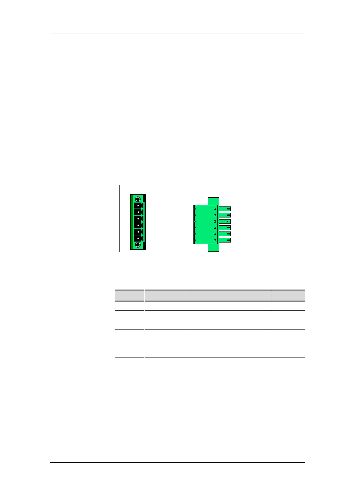
5.1 Connector X1
The 6-pin connector is on top of the housing. The 24 V power supply to
the SIMOLINK Pulse Generator is connected via X1.
M
+24 V
ConnectorSocket X1
Fig. 5-1
Terminal Designation Meaning Range
1 - Unused
2 - Unused
3 - Unused
4 - Unused
5 M Ground
6 +24V 24 V power supply +21 ... 28 V
Connectable cross-section: 1.5 mm2 (AWG 16)
Terminal 1 is the terminal to the rear of the module top plate (see plan view).
Table 5-1 Connector assignments
Siemens AG GWE-477 764 4070.76 J
SIMOVERT MASTERDRIVES Operating Instructions 5-1
Page 16
Connections 02.2001 SIMOLINK Pulse Generator
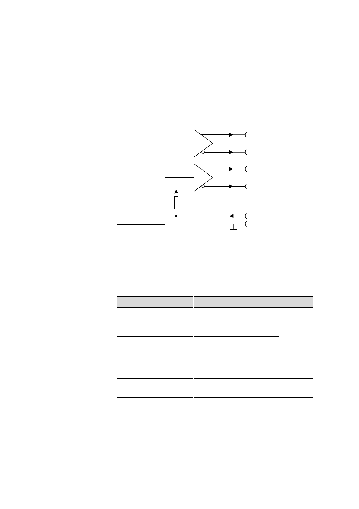
5.2 Encoder interface X2
The encoder interface of the SIMOLINK Pulse Generator is the 9-pin,
SUB D socket with screw locking mechanism (UNC) on the front of the
housing. Two RS422 drivers each supply two signals per pulse output,
one signal with non-inverted signal level and one signal with inverted
signal level. The driver voltage supply circuit is isolated from the 24 V
supply for the module.
2
A+
7
A
−
4
Frequency
generator
P5
B+
9
B
−
1
SEL_100 kHz
3,8
GND
Fig. 5-2 Schematic of output circuit (connector X2)
The two operating modes "90° pulses" and "100 kHz signal" are
selected via a jumper in the encoder connector. The 90° pulses setting
is the default and is activated when pin 1 in the encoder interface is
unused.
Pin Signal Meaning for 90° pulses Range
2 A+ Track A not inverted RS422
7 A– Track A inverted standard
4 B+ Track B not inverted RS422
9 B– Track B inverted standard
1 SEL_100 kHz Do not assign,
selection of 100-kHz signal
3, 8 GND Ground (see below) jumper to
5, 6 n.c. Unused
Housing Outer shield
Do not
insert
GND!
9-pin SUB D socket with screw locking mechanism (UNC)
Table 5-2 Assignment of connector X2 for 90° pulses mode
GWE-477 764 4070.76 J Siemens AG
5-2 Operating Instructions SIMOVERT MASTERDRIVES
Page 17

SIMOLINK Pulse Generator 02.2001 Connections
The SIMOLINK Pulse Generator can be switched over to the other
mode "100 kHz signal“ through insertion of a jumper between
connector pin "SEL_100kHz" and GND.
Pin Designation Meaning for 100 kHz signal Range
2 A+ Track A 100 kHz not inverted RS422
7 A– Track A 100 kHz inverted standard
4 B+ Sign not inverted RS422
9 B– Sign inverted standard
1 SEL_100 kHz Selection of 100 kHz signal Insert
3, 8 GND Ground (see below)
5, 6 n.c. Unused
Housing Outer shield
jumper to
GND!
9-pin SUB D socket with screw locking mechanism (UNC)
Table 5-3 Assignment of connector X2 for 100 kHz signal mode
NOTICE
CAUTION
To maintain immunity to interference, a shielded cable must be used
and the shield attached in the connector housing.
One or several drives/devices can be connected to the SLP module.
When the SLP is operated in conjunction with one drive/device, the
GND signal should be connected in the cable. If several drives/devices
are connected to the SLP, the GND signal should not be connected; it
must be noted in this respect that large deviations in the 0 V (GND) on
different drives/devices can cause disturbances or malfunctions on the
RS422 bus.
Siemens AG GWE-477 764 4070.76 J
SIMOVERT MASTERDRIVES Operating Instructions 5-3
Page 18
Connections 02.2001 SIMOLINK Pulse Generator
Signal output
90°pulses
Signal output
100 kHz signal
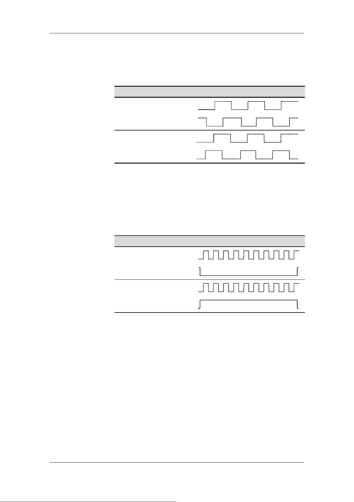
The SIMOLINK Pulse Generator produces two signals with a phase
displacement of ± 90°. The pulse-pause ratio for each of these signals
is 1:1.
Setpoint input Signal shape at output
Track A
Positive setpoint
Track B
Track A
Negative setpoint
Track B
Fig. 5-3 Signal shape in 90° pulses mode
In the "100 kHz signal“ mode, track A outputs 4 times the frequency,
i.e. 100 kHz correspond to 100%. Track B supplies the sign according
to the following rule: The signal is low for positive setpoints and high for
negative setpoints.
Setpoint input Signal shape at output
Positive setpoint
Track A
Track B
Track A
Negative setpoint
Track B
Fig. 5-4 Signal shape in 100 kHz signal mode
GWE-477 764 4070.76 J Siemens AG
5-4 Operating Instructions SIMOVERT MASTERDRIVES
Page 19

SIMOLINK Pulse Generator 02.2001 Connections
5.3 Fiber-optic cable connection
The fiber-optic cables are connected via plug-and-socket connectors.
The transmit and receive sockets are on the bottom of the housing (Fig.
4-2). The output power of the fiber-optic transmitter is not variable, but
permanently set to the maximum transmitter power defined for
SIMOLINK.
SIMOLINK is a clocked, ring-shaped
fiber-optic bus system. To allow the
flow of signal traffic, the transmit
socket of the first node must be
connected to the receive socket of
the next node and so on, until the
transmit socket of the last node is
connected to the receive socket of
the first node.
The receive socket is dark grey and
labeled RX. The transmit socket is
light gray and labeled TX.
The following Hewlett Packard fiberoptic modules are installed in the
SIMOLINK Pulse Generator :
♦ Transmitter: HFBR 1528
♦ Receiver: HFBR 2528
Fig. 5-5 Bus connector
RX
TX
Fig. 5-6 Fiber-opt i c
connector
NOTE
NOTICE
Plastic or glass fiber-optic cables can be used. Depending on the type
of cable selected, the inter-node distances are as follows:
♦ Max. 40 m between each node in the case of plastic cables or
♦ Max. 300 m between each node in the case of glass cables.
The maximum permissible ring bus length is 1000 m.
A components package for assembling plastic fiber-optic cable
connections can be ordered under number 6SX7010-0FJ50. This
contains: 100 m plastic fiber-optic cable, 40 fiber-optic connectors, 20
connectors for terminal strip X470 SLB.
If glass fiber optics are the selected medium, the connectors attached
to the fiber-optic cable must be suitable, i.e. they must fit into the
transmit and receive sockets on the SIMOLINK Pulse Generator.
Siemens AG GWE-477 764 4070.76 J
SIMOVERT MASTERDRIVES Operating Instructions 5-5
Page 20

Connections 02.2001 SIMOLINK Pulse Generator
How to assemble a
bus cable
To make connections on a plastic fiber-optic cable, please follow the
instructions below:
1. Cut the correct length of fiber-optic cable. Make sure you cut the
cable at right angles, use a sharp knife. (Fig. 5-7 )
2. Remove approximately 7 mm of the outer, black sheath on the cable
using a suitable cable stripping device. Take great care not to
damage the fiber optic when removing the sheath!
3. Insert the fiber-optic cable into the connector (Fig. 5-7 ó) and push
it into the cylindrical sleeve as far as it will go. The transparent fiber
optic will protrude out of the other side of the sleeve.
4. Fold round the gripping half of the connector and close it by hand
(Fig. 5-7 ì). Once the top half of the connector is latched into the
lower half, the cable is lodged securely in the connector.
5. Use a sharp knife to cut the protruding end of the cable almost flush
with the connector surface. Cut at right angles to the fiber-optic
cable axis.
6. You now need to polish the surface of the fiber optic. To do this,
place the end of the sleeve flat on the surface of the matt, rough
side of the green polishing paper supplied, and "draw" a figure of 8.
Then clean the end with a clean, lint-free cloth.
7. The sleeve end can be polished finely to reduce throughput losses
to a minimum. Fine polishing reduces throughput losses by
approximately 2 dB. To fine polish the sleeve, place it vertically on
the matt, rough side of the pink polishing paper and "draw" a figure
of 8 about 25 times. Then clean the end again with a clean, lint-free
cloth.
Cut fiber-optic
cable to length
Fig. 5-7 Connecting a plastic cable
Insert cable i n
connector
ìó
Close
connector
GWE-477 764 4070.76 J Siemens AG
5-6 Operating Instructions SIMOVERT MASTERDRIVES
Page 21

SIMOLINK Pulse Generator 02.2001 Start-Up
6 Start-Up
6.1 Setting the DIL switch
The SIMOLINK receive address (in dispatcher mode, address of the
node transmitting the speed setpoint to the SLP) for the SIMOLINK
Pulse Generator is set by means of an 8-channel DIL switch on the
front of the housing. The receive channel cannot be set; its default
setting is 0.
0
2
CHANNEL
7
2
Fig. 6-1 DIL switch for read address (address =75)
ON
Switch Designation Meaning Range
.1 2
0
= 1
.2 (21)= 2
.3 (22)= 4
Channel
.4 (23)= 8
.5 (24)= 16
.6 (25)= 32
SIMOLINK receive address
Note:
Switch 1 is the least significant bit.
Switch position on right means "1“ or
"ON“.
0…200
.7 (26)= 64
.8 2
7
Channel 1 of the DIL switch is at the top of the housing front panel in the assembled
state.
=128
Table 6-1 Value assignments for DIL switch
When set via the DIL switches, the receive address is directly
transferred and the setpoint contained in the receive telegram is
available as an output frequency at the encoder interface.
NOTICE
Address settings 201 to 255 are invalid, LEDs "SYNC“ and "FREQ“
flash alternately and no frequency is output.
Siemens AG GWE-477 764 4070.76 J
SIMOVERT MASTERDRIVES Operating Instructions 6-1
Page 22

Start-Up 02.2001 SIMOLINK Pulse Generator
6.2 LED displays
The status of the SIMOLINK Pulse Generator is displayed on three
green LEDs on the housing front panel.
SIMOLINK
PULS GENERATOR SLP
POWER
Fig. 6-2 SLP display
LED Description
POWER SYNC FREQ
l
l
ll
lll
SYNC
FREQ
Device not connected to supply voltage
No + 24 V supply voltage available
Supply voltage connected:
SYNC interrupt is not being received
DIL switch is incorrectly set
SIMOLINK receive address higher than >200 set (alternate flashing
of SYNC and FREQ LEDs)
SYNC interrupt is being received:
Setpoint = 0 % or 0 Hz output frequency or
setpoint telegram is not being receiv ed
FREQ LED flashes at the output frequency:
Setpoint telegram is being received and setpoint not equal to 0 %
(flashing is perceptible at very low setpoints only)
LED off
l LED illuminated continuously
LED flashing (approximately twice per second)
Table 6-2 SLP operating states
NOTICE
An illuminated POWER LED does not necessarily confirm that the
supply voltage level is correct. The operator is responsible for ensuring
that the voltage supply remains stable within the specified limits.
GWE-477 764 4070.76 J Siemens AG
6-2 Operating Instructions SIMOVERT MASTERDRIVES
Page 23

SIMOLINK Pulse Generator 02.2001 Start-Up
6.3 SIMOLINK data interface
The SIMOLINK data interface comprises a single-channel SIMOLINK
receive data word; it does not provide a transmit channel. It expects the
speed setpoint for the frequency generator in receive channel 0 of the
set receive address. The setpoint is read in the MASTERDRIVES 32-bit
format (4000 0000 hex = 100 %); only the 10 highest bits are resolved,
corresponding to a speed resolution of 0.4 %.
32-bit setpoint from SIMOLINK receive telegram
31 22 16 15 0
Evaluated by the SLP Irrelevant
Fig. 6-3 SLP setpoint telegram
The frequency generator has a frequency range of 0 Hz to 112 kHz (at
a rated frequency of 100 kHz). In the 90° pulses mode (4 edges
required for correct signal sequence from tracks A and B), the resulting
rated output frequency per track is 25 kHz and a maximum possible
setpoint output of approximately 112 %.
32-bit setpoint
(hex)
47C0 0000 + 112.1 28.027 112.1 kHz / Low
4780 0000 + 111.7 27.930 111.7 kHz / Low
4000 0000 + 100.0 25.000 100.0 kHz / Low
0000 0000 0.0 0.000 0.0 kHz / Low
C000 0000 − 100.0 25.000 100.0 kHz / High
B880 0000 − 111.7 27.930 111.7 kHz / High
B840 0000 − 112.1 28.027 112.1 kHz / High
NOTICE
Setpoint
[%]
Table 6-3 Relationship between setpoint and output frequency
Output frequency in
90°pulses mode [kHz]
Frequency in
100 kHz / sign mode
When the setpoint exceeds 112 %, the SIMOLINK Pulse Generator
outputs the maximum frequency of approximately 28 kHz. If "100 kHz
signal“ mode is active, then approximately 112 kHz.
Siemens AG GWE-477 764 4070.76 J
SIMOVERT MASTERDRIVES Operating Instructions 6-3
Page 24

Start-Up 02.2001 SIMOLINK Pulse Generator
Response to errored
SIMOLINK telegrams
Setpoint adjustment
to the machine
velocity
The SIMOLINK Pulse Generator updates the setpoint output in
response to every SYNC interrupt with which error-free data are
received. If a communications error occurs, the generator continues to
operate on the old setpoint. If CRC errors occur 8 times in succession,
it sets the frequency generator directly to 0 Hz and does not restart it
until an error-free setpoint is received. It switches to 0 Hz immediately if
communication on the SIMOLIN K is abort ed.
The frequency output of the SIMOLINK pulse generator in the 90°
pulses mode is identical to that of a pulse generator with 1000
pulses/rev and a speed normalization of 1 00 % = 1500 rev/min. If the
generator is to simulate shaft encoders with other pulse numbers per
revolution or different speed normalization, the setpoint to the SLP must
be renormalized. This can be done, for example, by multiplying the
machine setpoint. In this regard, it is important to note that the
maximum setpoint for the SLP on the SIMOLINK data interface must
not exceed 112 % (max. output frequency of approximately 28 kHz in
90° pulse mode).
Multiplier
=
×
×
frequency Output60
pulses/rev Encoder speed Reference
% 100x
Output frequency depending on operating mode:
♦ 25000 In 90° pulse mode
♦ 100000 In 100 kHz signal mode
Reference speed
[rev/min]
500 1000 33.333
1000 1000 66.667
1000 2000 133.333
1500 1000 100.000
1500 1024 102.400
1500 2048 Not displayable
1)
The speed range of the SLP cannot be output with this combination
Table 6-4 Examples for 90° pulses mode
No. of encoder
pulses per rev.
Multiplier
[%]
1)
GWE-477 764 4070.76 J Siemens AG
6-4 Operating Instructions SIMOVERT MASTERDRIVES
Page 25
SIMOLINK Pulse Generator 02.2001 Start-Up
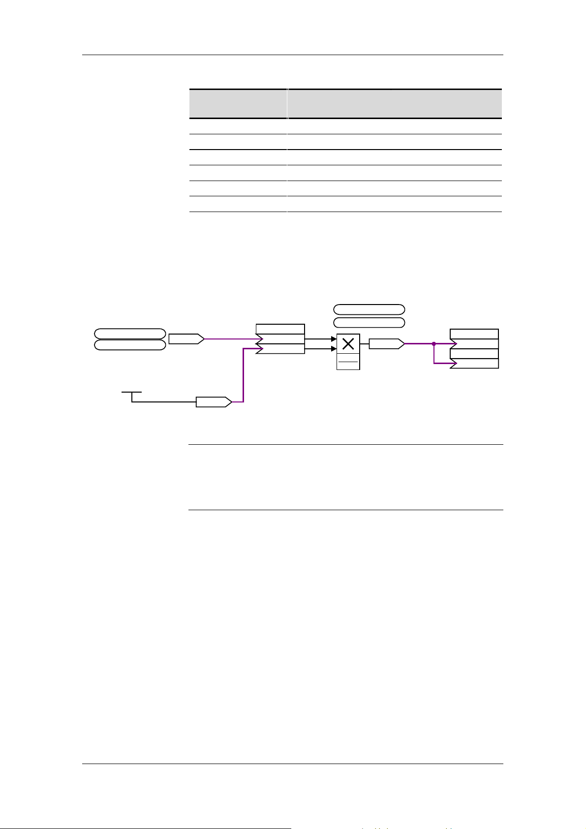
a
Parameterization
example
Speed setpoint for
virtual master axis from
ramp-func t ion generator
U961.51 =
U951.51 = 04 (20)
Calcu lated m ultiplier in %
U014.F (0.000 %)
X
Reference speed
[rev/min]
No. of encoder
pulses per rev.
500 1024 8.53
1000 2000 66.66
1500 2048 51.200
2000 5000 166.667
2500 2000 83.333
3000 2000 100.000
1)
The speed range of the SLP cannot be output with this combination
Table 6-5 Examples for 100 kHz signal mode
KK0571
KK0414
U110 (0)
K 571
K 414
.01
.02
U961.31 =
U951.31 = 04 (20)
x1
x2
x1x2
100 %
X+n
y
KK0470
⋅
Multiplier
[%]
1)
SLB transmit dat
P751.1
P751.2
(0)
KK470
(0)
KK470
NOTICE
Fig. 6-4 Example of setpoint normalization parameter settings
The processing time slot and sequence must be taken into account in
the parameter settings. If a time slot other than the time slot for setpoint
calculation is used or the processing sequence altered, the resulting
dead times will cause a lag in the signal output when the setpoint is
changed.
Siemens AG GWE-477 764 4070.76 J
SIMOVERT MASTERDRIVES Operating Instructions 6-5
Page 26

Bisher sind folgende Ausgaben erschienen: Ausgabe Interne Sachnummer
AA GWE-477 764 4070.76 J AA-76
Ausgabe AA besteht aus folgenden Kapiteln:
Kapitel Änderungen Seitenzahl Ausgabedatum
1 Definitionen und Warnungen Erstausgabe 3 02.2001
2 Produktbeschreibung Erstausgabe 2 02.2001
3 Technische Daten Erstausgabe 1 02.2001
4 Montage Erstausgabe 2 02.2001
5 Anschließen Erstausgabe 6 02.2001
6 Inbetriebsetzen Erstausgabe 5 02.2001
The following editions have been published so far: Edition Internal Item Number
AA GWE-477 764 4070.76 J AA-76
Version AA consists of the following chapters:
Chapter Changes Pages Version date
1 Definitions and Warnings first edition 3 02.2001
2 Product Description first edition 2 02.2001
3 Technical Data first edition 1 02.2001
4 Installation first edition 2 02.2001
5 Connections first edition 6 02.2001
6 Start-up first edition 5 02.2001
Group: Automation and Drives (A&D)
Division: Variable-Speed Dri ve S ystems
Postfach 3269, D-91050 Erlangen
Siemens Aktiengesellschaft Subject to change GWE-477 764 4070.76
Printed in the Federal Republic of Germany
02.2001
 Loading...