

Siemens Simovert P 6SE21 Series Operating Instructions Manual

SIMOVERT P 6SE21 Series Inverters
English
Operating Instructions
Siemens plc 1995
G85139–A1615–U156–A
02.95
3
Contents Page
Warning and Caution Notes . . . . . . . . . . . . . . . . . . . . . . . . . . . . . . . . . . . . . . . . . . . . . . . . . . . . . . . . . . . . . . . . . . . . 5
1. DESCRIPTION . . . . . . . . . . . . . . . . . . . . . . . . . . . . . . . . . . . . . . . . . . . . . . . . . . . . . . . . . . . . . . . . . . . . . . . . . . . . 7
1.1 Introduction . . . . . . . . . . . . . . . . . . . . . . . . . . . . . . . . . . . . . . . . . . . . . . . . . . . . . . . . . . . . . . . . . . . . . . . . . . . .
1.2 Control Facilities . . . . . . . . . . . . . . . . . . . . . . . . . . . . . . . . . . . . . . . . . . . . . . . . . . . . . . . . . . . . . . . . . . . . . . . .
1.3 Monitoring Facilities . . . . . . . . . . . . . . . . . . . . . . . . . . . . . . . . . . . . . . . . . . . . . . . . . . . . . . . . . . . . . . . . . . . . .
1.4 Motor Characteristics . . . . . . . . . . . . . . . . . . . . . . . . . . . . . . . . . . . . . . . . . . . . . . . . . . . . . . . . . . . . . . . . . . . .
1.4.1 Voltage/Frequency Characteristic . . . . . . . . . . . . . . . . . . . . . . . . . . . . . . . . . . . . . . . . . . . . . . . . . . . . . .
1.4.2 Low Frequency Voltage Boost (Ku) . . . . . . . . . . . . . . . . . . . . . . . . . . . . . . . . . . . . . . . . . . . . . . . . . . . .
1.4.3 Current Limit . . . . . . . . . . . . . . . . . . . . . . . . . . . . . . . . . . . . . . . . . . . . . . . . . . . . . . . . . . . . . . . . . . . . . . . .
1.5 Options . . . . . . . . . . . . . . . . . . . . . . . . . . . . . . . . . . . . . . . . . . . . . . . . . . . . . . . . . . . . . . . . . . . . . . . . . . . . . . . .
7
8
9
9
9
10
10
10
2. TECHNICAL DATA . . . . . . . . . . . . . . . . . . . . . . . . . . . . . . . . . . . . . . . . . . . . . . . . . . . . . . . . . . . . . . . . . . . . . . . . . 11
2.1 Equipment Ratings Table . . . . . . . . . . . . . . . . . . . . . . . . . . . . . . . . . . . . . . . . . . . . . . . . . . . . . . . . . . . . . . . . .
2.2 Cable Lengths . . . . . . . . . . . . . . . . . . . . . . . . . . . . . . . . . . . . . . . . . . . . . . . . . . . . . . . . . . . . . . . . . . . . . . . . . . 1111
3. MECHANICAL INSTALLATION . . . . . . . . . . . . . . . . . . . . . . . . . . . . . . . . . . . . . . . . . . . . . . . . . . . . . . . . . . . . . . 12
4. ELECTRICAL INSTALLATION . . . . . . . . . . . . . . . . . . . . . . . . . . . . . . . . . . . . . . . . . . . . . . . . . . . . . . . . . . . . . . . 14
4.1 Mains Input / Motor Connections . . . . . . . . . . . . . . . . . . . . . . . . . . . . . . . . . . . . . . . . . . . . . . . . . . . . . . . . . .
4.2 Control Connections . . . . . . . . . . . . . . . . . . . . . . . . . . . . . . . . . . . . . . . . . . . . . . . . . . . . . . . . . . . . . . . . . . . . . 1416
5. COMMISSIONING . . . . . . . . . . . . . . . . . . . . . . . . . . . . . . . . . . . . . . . . . . . . . . . . . . . . . . . . . . . . . . . . . . . . . . . . . . 18
5.1 Preparation for Switch–On . . . . . . . . . . . . . . . . . . . . . . . . . . . . . . . . . . . . . . . . . . . . . . . . . . . . . . . . . . . . . . .
5.1.1 Starting and Stopping the Inverter . . . . . . . . . . . . . . . . . . . . . . . . . . . . . . . . . . . . . . . . . . . . . . . . . . . . .
5.1.2 Direction of Rotation . . . . . . . . . . . . . . . . . . . . . . . . . . . . . . . . . . . . . . . . . . . . . . . . . . . . . . . . . . . . . . . . .
5.1.3 Jog Feature . . . . . . . . . . . . . . . . . . . . . . . . . . . . . . . . . . . . . . . . . . . . . . . . . . . . . . . . . . . . . . . . . . . . . . . .
5.1.4 Speed Control . . . . . . . . . . . . . . . . . . . . . . . . . . . . . . . . . . . . . . . . . . . . . . . . . . . . . . . . . . . . . . . . . . . . . .
5.2 First Switch–On . . . . . . . . . . . . . . . . . . . . . . . . . . . . . . . . . . . . . . . . . . . . . . . . . . . . . . . . . . . . . . . . . . . . . . . . .
5.3 Parameterisation . . . . . . . . . . . . . . . . . . . . . . . . . . . . . . . . . . . . . . . . . . . . . . . . . . . . . . . . . . . . . . . . . . . . . . . .
5.3.1 Changing Parameter Settings . . . . . . . . . . . . . . . . . . . . . . . . . . . . . . . . . . . . . . . . . . . . . . . . . . . . . . . . .
5.3.2 Parameter Descriptions . . . . . . . . . . . . . . . . . . . . . . . . . . . . . . . . . . . . . . . . . . . . . . . . . . . . . . . . . . . . . .
5.4 Fault Indications . . . . . . . . . . . . . . . . . . . . . . . . . . . . . . . . . . . . . . . . . . . . . . . . . . . . . . . . . . . . . . . . . . . . . . . .
5.5 Fault Relay . . . . . . . . . . . . . . . . . . . . . . . . . . . . . . . . . . . . . . . . . . . . . . . . . . . . . . . . . . . . . . . . . . . . . . . . . . . . .
18
18
20
20
20
20
21
21
22
30
31
6. USING CLOSED LOOP SPEED CONTROL . . . . . . . . . . . . . . . . . . . . . . . . . . . . . . . . . . . . . . . . . . . . . . . . . . . 32
6.1 Introduction . . . . . . . . . . . . . . . . . . . . . . . . . . . . . . . . . . . . . . . . . . . . . . . . . . . . . . . . . . . . . . . . . . . . . . . . . . . .
6.2 Installation of Control Loop Speed Control . . . . . . . . . . . . . . . . . . . . . . . . . . . . . . . . . . . . . . . . . . . . . . . . . .
6.2.1 Scaling Factor of ‘Actual Speed’ . . . . . . . . . . . . . . . . . . . . . . . . . . . . . . . . . . . . . . . . . . . . . . . . . . . . . . .
6.2.2 Speed Control Operation . . . . . . . . . . . . . . . . . . . . . . . . . . . . . . . . . . . . . . . . . . . . . . . . . . . . . . . . . . . . .
6.2.3 Speed Control Optimisation . . . . . . . . . . . . . . . . . . . . . . . . . . . . . . . . . . . . . . . . . . . . . . . . . . . . . . . . . . .
6.2.4 Slip Limit (P35) . . . . . . . . . . . . . . . . . . . . . . . . . . . . . . . . . . . . . . . . . . . . . . . . . . . . . . . . . . . . . . . . . . . . . .
6.2.5 Sample Rate (P36) . . . . . . . . . . . . . . . . . . . . . . . . . . . . . . . . . . . . . . . . . . . . . . . . . . . . . . . . . . . . . . . . . .
32
32
32
33
33
33
33
7. QUICK REFERENCE GUIDE . . . . . . . . . . . . . . . . . . . . . . . . . . . . . . . . . . . . . . . . . . . . . . . . . . . . . . . . . . . . . . . . 34
7.1 Connections . . . . . . . . . . . . . . . . . . . . . . . . . . . . . . . . . . . . . . . . . . . . . . . . . . . . . . . . . . . . . . . . . . . . . . . . . . . .
7.2 Parameter List . . . . . . . . . . . . . . . . . . . . . . . . . . . . . . . . . . . . . . . . . . . . . . . . . . . . . . . . . . . . . . . . . . . . . . . . . .
7.3 Fault Codes . . . . . . . . . . . . . . . . . . . . . . . . . . . . . . . . . . . . . . . . . . . . . . . . . . . . . . . . . . . . . . . . . . . . . . . . . . . .
34
35
35

SIMOVERT P 6SE21 Series Inverters
English
Operating Instructions
Siemens plc 1995
G85139–A1615–U156–A
02.95
4
Contents (continued) Page
Figures
1 Block Diagram Simovert P 6SE21 . . . . . . . . . . . . . . . . . . . . . . . . . . . . . . . . . . . . . . . . . . . . . . . . . . . . . . . . . . . .
2 Voltage/Frequency Characteristic Curves . . . . . . . . . . . . . . . . . . . . . . . . . . . . . . . . . . . . . . . . . . . . . . . . . . . . . .
3 Connection Diagram . . . . . . . . . . . . . . . . . . . . . . . . . . . . . . . . . . . . . . . . . . . . . . . . . . . . . . . . . . . . . . . . . . . . . . . .
4 Connection Example . . . . . . . . . . . . . . . . . . . . . . . . . . . . . . . . . . . . . . . . . . . . . . . . . . . . . . . . . . . . . . . . . . . . . . . .
5 Fault Code Table . . . . . . . . . . . . . . . . . . . . . . . . . . . . . . . . . . . . . . . . . . . . . . . . . . . . . . . . . . . . . . . . . . . . . . . . . . .
6 Closed Loop Speed Control . . . . . . . . . . . . . . . . . . . . . . . . . . . . . . . . . . . . . . . . . . . . . . . . . . . . . . . . . . . . . . . . . .
8
10
15
17
30
32
Note
These instructions do not purport to cover all details or variations in equipment, nor to provide for every
possible contingency to be met in connection with installation, operation or maintenance.
Should further information be desired or should particular problems arise which are not covered sufficiently
for the Purchaser’s purposes, the matter should be referred to the local Siemens Sales Office.
The contents of this instruction manual shall not become part of or modify any prior or existing agreement,
commitment or relationship. The Sales Contract contains the entire obligations of Siemens. The warranty
contained in the contract between the parties is the sole warranty of Siemens. Any statements contained
herein do not create any new warranties or modify the existing warranty.

SIMOVERT P 6SE21 Series Inverters
English
Operating Instructions
Siemens plc 1995
G85139–A1615–U156–A
02.95
5
Warning and Caution Notes
This equipment contains hazardous voltages and controls hazardous rotating mechanical parts. Loss
of life, severe personal injury or property damage can result if instructions contained in this manual
are not followed.
Only suitable qualified personnel should work on this equipment, and only after becoming familiar with
all safety notices, installation, operation and maintenance procedures contained in this manual. The
successful and safe operation of this equipment is dependent upon its proper handling, installation,
operation and maintenance.
WARNING
Definitions
• Qualified Person
For the purposes of this manual and product labels, a qualified person is one who is familiar with the installation,
construction, operation and maintenance of this equipment and with the hazards involved. In addition, the person must
be:
(1) Trained and authorised to energise, de–energise, clear, ground and tag circuits and equipment in
accordance with established safety practices.
(2) Trained in the proper care and use of protective equipment in accordance with established safety
practices.
(3) Trained in rendering first aid.
• DANGER
For the purposes of this manual and product labels, DANGER indicates that loss of life, severe personal injury or
substantial property damage WILL result if proper precautions are not taken.
• WARNING
For the purposes of this manual and product labels, WARNING indicates that loss of life, severe personal injury or
substantial property damage CAN result if proper precautions are not taken.
• CAUTION
For the purposes of this manual and product labels, CAUTION indicates that minor personal injury or property damage
CAN result if proper precautions are not taken.
• Note
For the purposes of this manual and product labels, Notes merely call attention to information that is especially
significant in understanding and operating the drive.

SIMOVERT P 6SE21 Series Inverters
English
Operating Instructions
Siemens plc 1995
G85139–A1615–U156–A
02.95
6
Hot Line
Siemens operates a telephone ‘hot line’ for users of their 6SE21 range of
inverters. This service is available during normal working hours, Monday to
Friday. If you require assistance, contact our customer support personnel
on the following number:
Tel: (49) 9131 7 23212
Fax: (49) 9131 7 29900
Please have the following information available before dialling:
•
inverter model number
•
hardware type (stored in P49)
•
software version (stored in P50)

SIMOVERT P 6SE21 Series Inverters
English
Operating Instructions
Siemens plc 1995
G85139–A1615–U156–A
02.95
7
1. DESCRIPTION
SIMOVERT P transistorised voltage–source inverters operate with high voltages.
Connection, commissioning and fault–finding should only be carried out by qualified personnel who
are fully conversant with the relevant documentation, installation regulations, etc.
Only permanently–wired input power connections are allowed. This equipment must be grounded
(IEC 536 Class 1, NEC and other applicable standards).
Safety Note:
Do not apply input power to the equipment when the plastic cover has been removed. Dangerous
voltages are present within the equipment which could cause serious injury or death if touched. After
removing mains power, always allow a minimum of five minutes for the internal capacitors to
discharge before removing the cover.
When the 3–phase mains input is protected by a current–operated earth–leakage breaker, the input
to the inverter must be isolated from the mains if the earth–leakage breaker is to operate effectively.
The dc–link capacitors remain charged to dangerous voltages for up to five minutes after the incoming
power has been switched off.
When the motor is not running, dangerous voltages are still present on the power input terminals AND
motor output terminals and also on the dc–link terminals.
Under certain set–up conditions, the inverter may restart automatically after an input power failure.
WARNING
1.1 Introduction
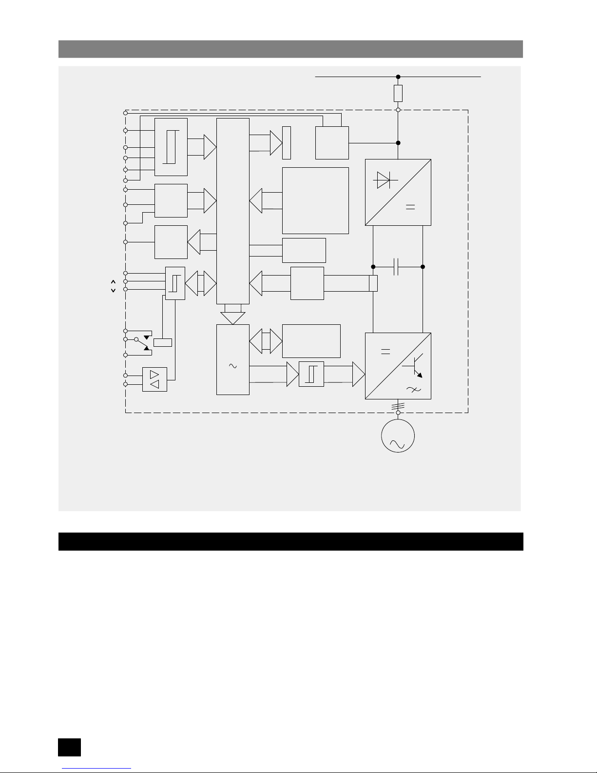
SIMOVERT P inverters of the 6SE21 series are designed for low–loss speed control of three–phase motors. This is
achieved by rectifying input voltage to establish a dc link voltage, and modulating this link voltage with a three–phase
transistor bridge to produce a Pulse–Width Modulated (PWM) three–phase output voltage
(see Figure 1)
. The
inductance of the motor windings converts this PWM voltage to a sinusoidal motor current. By varying the frequency of
this sinusoidal current, the rotational speed of the motor is controlled without significantly affecting the losses in the
motor. The output frequency can be adjusted between 0 and 400 Hz.
SIMOVERT P 6SE21 Series Inverters
English
Operating Instructions
Siemens plc 1995
G85139–A1615–U156–A
02.95
8
Block Diagram – SIMOVERT P 6SE21
Figure 1:
3
M
PWM
SE
PROM
CPU
A/D
D/A
SV
SI
GR
ZK
WR
Run/Stop
0 – 10 V
0 – 20 mA
4 – 20 mA
BUS
+
Power Supply
Mains Fuse(s)
DC Link
Power Supply
Microprocessor
Analog/Digital Converter
Bus Connector
GR Rectifier
WR Inverter
SE Current Monitoring
PWM Pulse Width Modulator
D/A Digital/Analog Converter
R/L Clockwise/Counter–clockwise
Frequency, Current Indicator
Jog
FRONT
PANEL
F
u/Iu
PROM
Fault
Trip
Tacho
F
u/Iu
P
RS485
X11
X1
X1
ZK
CPU
A/D
BUS
+15 V
+10 V
2
3
4
13
6
7
9
12
11
16
17
18
19
20
21
14
15
SI
SV
R/L
5
1.2 Control Facilities
The inverter can be started/stopped by any of the following means
(see parameter P05 in section 5.3.2 and also Figure
3)
:
(1) Connection of a latching switch to the run/stop input (terminals X11.2/3).
(2) Applying a rising edge (i.e. momentary push–button) to the Run/Stop input (terminals X11.2/3) and a falling
edge to the trip input terminal X11.2/4.
(3) Connection of a voltage level of 7 – 33 V to the Run/Stop input (terminals X11.3/1).
(4) Automatic starting on application of input power (shorting link terminals X11.2/3).
(5) Connection of a voltage level of 7 – 33 V to the jog input (terminal X11.13/1).
(6) Control via the serial I/O connections.

SIMOVERT P 6SE21 Series Inverters
English
Operating Instructions
Siemens plc 1995
G85139–A1615–U156–A
02.95
9
The output frequency of the inverter, and hence the speed of the motor , can be controlled by any of the following means
(see 5.3.2, parameter P04 and also Figure 3)
:
(1) Connection of 0–10 V control voltage (terminals X11.7/8).
(2) Connection of a 0–20 mA current loop control input (terminals X11.9/10).
(3) Connection of a 4–20 mA current loop control input (terminals X11.9/10).
(4) Connection of a 5 kΩ control potentiometer (terminals X11.6/7/8).
(5) By digital parameterisation via the push–buttons fitted to the inverter, or via equivalent external push–buttons
connected to terminals X11.17 and X11.18.
(6) Via the serial I/O connection.
1.3 Monitoring Facilities
The following monitoring facilities are available:
(1) Seven–segment display for output frequency, output current, fault indication or parameterisation. This is
viewed through a window in the cover.
(2) A 0–10 V analogue signal, proportional to output frequency or output current.
(3) A changeover relay, normally energised when the drive is connected to a suitable input supply . The relay is
de–energised when a fault is indicated
(see section 5.5)
.
(4) The drive may be interrogated via the serial I/O connection.
1.4 Motor Characteristics
The inverter can be adjusted to suit individual motor characteristics in the ways described in 1.4.1 and 1.4.2.
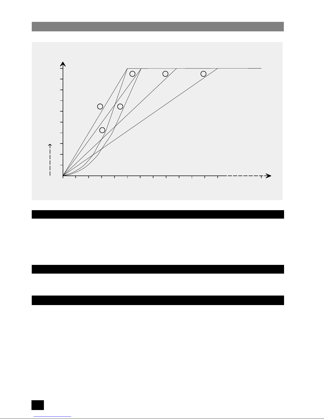
1.4.1 Voltage/Frequency Characteristic
Six voltage/frequency characteristic curves are available plus one programmable curve
(see Figure 2)
. They are
intended for the following applications:
Curve 0: V
N/50 Hz (constant torque)
For standard 50 Hz induction motors with linear speed/torque characteristics.
Curve 1: V
N/60 Hz (constant torque)
For standard 60 Hz induction motors with linear speed/torque characteristics.
Curve 2: V
N/87 Hz (constant torque)
For delta–connection of standard induction motors designed for star–connection of 50 Hz input voltage.
This increases the speed range over which constant motor torque can be achieved.
Curve 3: V
N/120 Hz (constant torque)
For applications where a constant torque is required over the full operating speed range 0.1 to 120 Hz.
Curve 4*: V
N/50 Hz (torque proportional to speed
1.5
)
For operation of 50 Hz motors driving loads where torque is proportional to (speed)
1.5
. Typical examples
of such loads are fans and pumps.
Curve 5*: V
N/60 Hz (torque proportional to speed
1.5
)
For operation of 60 Hz motors driving loads where torque is proportional to (speed)
1.5
.
Curve 6*: Programmable
(not shown in Figure 2)
The curve type and corner frequency may be selected by the user.
* Curves 4 and 5 allow variable torque output current values (see section 2.1) to be loaded into parameter P17. Curve
6 may allow variable torque output currents depending on the user–defined curve specified.
SIMOVERT P 6SE21 Series Inverters
English
Operating Instructions
Siemens plc 1995
G85139–A1615–U156–A
02.95
10
Figure 2:
Voltage/Frequency Characteristic Curves
0 10 20 30 40 50 60 70 80 90 100 110 120
10
20
30
40
50
60
70
80
90
100
Voltage
%
Frequency
0
1 2 3
4
5
Boost
Ku
400
1.4.2 Low Frequency Voltage Boost (Ku)
The output voltage can be boosted in 0.1% steps up to 30% for low frequencies from 0 Hz. This may be required to give
additional starting torque in some applications. The amount of voltage boost decreases linearly until 100% voltage is
achieved.
If required, automatic boost may be used
(see section 5.3.2, Parameter P19)
. This measures the motor characteristics
and selects a suitable boost voltage at first switch–on.
1.4.3 Current Limit
The maximum output current available from the inverter can be adjusted to provide thermal protection of the motor
and/or limit the maximum motor torque
(see section 5.3.2, parameters P17 and P18)
.
1.5 Options
The following options are available for use with 6SE21 inverters:
Sinewave Filter Module Part No. 6SE2100–1FC51/53/55
NAMUR Interface Module Part No. 6SE2100–1FC50/52/54
Relay Module * Part No. 6SE2100–1GA00
Tachometer Interface Unit * Part No. 6SE2100–1DA00
Clear Text Operator Panel * Part No. 6SE2100–1CA00
*
These options cannot be fitted in combination with each other.

SIMOVERT P 6SE21 Series Inverters
English
Operating Instructions
Siemens plc 1995
G85139–A1615–U156–A
02.95
11
2. TECHNICAL DATA
Rated supply voltage: Models 6SE21**–1AA1 1
Models 6SE21**–3AA21
** – May be any number
1 AC 50/60 Hz +/–1%, 220 – 240 V +/–10%
3 AC 50/60 Hz +/–1%, 380 – 500 V +/–10%
Output voltage 0 V – rated supply voltage
Output frequency 0.0 – 400 Hz
Efficiency ≥ 0.94
Motor power factor ≤ 0.9 lagging/inductive
Ambient operating temperature
(unit must not be exposed to direct sunlight)
0 – 40oC
Storage/transport temperature –30 – +85oC
Degree of protection IP21 (NEMA 1)
Humidity 0 – 95% at 25oC
Frequency stability at T
max
10oC referred to f
max
Analogue setpoint 1%
Digital setpoint 0.01%
Frequency resolution 0.1 Hz
Overload rating 1.5 x rated current for up to 60 seconds
2.1 Equipment Ratings Table
Input
Max.
Cont.
Circuit
Constant Torque
Output
Variable Torque
Output **
Variable Torque
Output **
460 V (USA)
Variable Torque
Output **
500 V
Overload
Model
6SE21..
Voltage
Range
Input
Current
Breaker
Continuous
Current
Motor
Rating *
Continuous
Current
Motor
Rating *
Continuous
Current
Motor
Rating *
Continuous
Current
Motor
Rating *
Current
01–1AA11
9.8 A 16.0 A 2.8 A .55 kW 3.9 A .75 kW – – – – 4.2 A
02–1AA11
198–264 V
1 phase
13.5 A 16.0 A 3.9 A .75 kW 4.8 A 1.1 kW – – – – 5.8 A
03–1AA11
1 phase
26.5 A 32.0 A 6.8 A 1.5 kW 10.0 A 2.2 kW – – – – 10.2 A
03–3AA21 5.5 A 10.0 A 4.0 A 1.5 kW 5.5 A 2.2 kW 4.8 A 3 hp 4.8 A 2.2 kW 6.0 A
05–3AA21 10.0 A 16.0 A 7.6 A 3.0 kW 9.5 A 4.0 kW 8.1 A 5 hp 8.1 A 4.0 kW 11.4 A
08–3AA21 17.0 A 20.0 A 12.0 A 5.5 kW 17.0 A 7.5 kW 14.0 A 10 hp 12.0 A 7.5 kW 18.0 A
13–3AA21
342–550 V
28.0 A 32.0 A 19.0 A 7.5 kW 23.0 A 11.0 kW 21.0 A 15 hp 19.0 A 11.0 kW 28.5 A
17–3AA21
342–550 V
3 phase
38.0 A 40.0 A 25.0 A 11.0 kW 32.0 A 15.0 kW 27.0 A 20 hp 25.0 A 15.0 kW 37.5 A
22–3AA21
40.0 A 50.0 A 32.0 A 15.0 kW 38.0 A 18.5 kW 34.0 A 25 hp 32.0 A 18.5 kW 48.0 A
27–3AA21 48.0 A 63.0 A 38.0 A 18.5 kW 46.0 A 22.0 kW 40.0 A 30 hp 38.0 A 22.0 kW 57.0 A
33–3AA21
70.0 A 80.0 A 46.0 A 22.0 kW 60.0 A 30.0 kW 52.0 A 40 hp 46.0 A 30.0 kW 69.0 A
42–3AA21 87.0 A 100.0 A 60.0 A 30.0 kW 75.0 A 37.0 kW 65.0 A 50 hp 60.0 A 37.0 kW 90.0 A
*
Siemens 4–pole motor, 1LA5 series or equivalent.
** Automatically selected on voltage/frequency curve types 4 and 5 (see section 1.4.1).
2.2 Cable Lengths
The inverters will operate satisfactorily with unscreened cables of up to 150 m in length and screened or armoured
cable of up to 50 m in length. For applications where longer cables are required, inductors must be fitted to reduce
capacitive currents.
Note
If long cables are used, it may be necessary to change the value of parameter P52 to compensate for any
inaccuracies in the output current reading.
The following chokes are suitable for applications where up to 100/200 m screened/unscreened cables are required:
Model No.
Choke Type
6SE210*–1AA11 & 6SE2103–3AA21 4EP3601–8DB
6SE2105–/6SE2108–3AA21 4EP3801–4DB
6SE2113–/6SE2117–/6SE2122–3AA21 4EP3800–4DB
6SE2127–/6SE2133–3AA21 4EP4002–1DB
6SE2142–3AA21 4EU2421–8AA00
SIMOVERT P 6SE21 Series Inverters
English
Operating Instructions
Siemens plc 1995
G85139–A1615–U156–A
02.95
12
3. MECHANICAL INSTALLATION
High voltages are generated within this equipment. It must only be installed and operated by qualified
personnel who are familiar with the equipment, its operating requirements and instructions.
The User is responsible for installation of the motor, drive controller, transformer and other devices
in accordance with regulations and local safety codes which may apply .
Adequate protective clothing (e.g. safety gloves, goggles, etc.) should be worn by the person
installing this equipment.
Failure to observe the appropriate warnings and regulations may result in serious injury or death.
WARNING
The inverter must be installed in a vertical position and fixed to a solid surface via its four mounting holes. It is suitable
for wall–mounting or installation within a cubicle.
All inverter variants are air–cooled. Ensure that a free space of at least 100 mm (4 in.) is left both above
and below the unit to allow an unimpeded air flow.
Avoid subjecting the inverter to excessive shock and vibration.
CAUTION
Installation drawings for the inverters are shown on the next page.
SIMOVERT P 6SE21 Series Inverters
English
Operating Instructions
Siemens plc 1995
G85139–A1615–U156–A
02.95
13
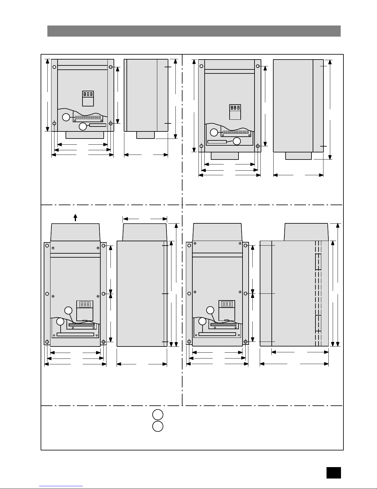
Dimension Drawings
SIEMENS SIMOVERT
A
B
Control Terminals X11
Mains Input/Motor Terminals X1
All dimensions in millimetres
185
209
197
144
257
197
293
SIEMENS SIMOVERT
A
B
375
325
225
249
237
411
162
SIEMENS SIMOVERT
Exhaust Air
COOLING FAN
258258
225
249
237
172
561
667
190
A
SIEMENS SIMOVERT
258258
225
249
237
561
667
315
250
6SE2101–1AA11
6SE2102–1AA11
6SE2103–1AA11
6SE2103–3AA21
6SE2105–3AA21
6SE2108–3AA21
6SE2113–3AA21
6SE2117–3AA21
6SE2122–3AA21
6SE2127–3AA21
6SE2133–3AA21
6SE2142–3AA21
Notes:
A
B
B
A
B
 Loading...