

Siemens Simovert Masterdrive FANC-SB, Simovert Masterdrive FANC-SBH Operating Instructions Manual
Page 1
SIMOVERT MASTERDRIVES
Operating Instructions
CBL – Communication Board CC-Link
Edition: AA Order No.: 6SE7087-6NX84-0GB0
All manuals and user guides at all-guides.com
all-guides.com
Page 2
Weitergabe sowie Vervielf äl tigung dieser Unterlage, Verwertung
und Mitteilung ihres Inhalts ni cht gestattet, soweit nicht ausdrück-
lich zugestanden. Zuwiderhandlungen verpflicht en zu Schadener-
satz. Alle Rechte vorbehalten, insbesondere für den Fall der
Patenterteilung oder GM-Eintragung.
Wir haben den Inhalt der Druckschrift auf Übereinstimmung mit
der beschriebenen Hard- und Software überprüft. Dennoch kön-
nen Abweichungen nicht ausgeschlossen werden, so daß wir für
die vollständige Übereinstimmung keine Garantie übernehmen.
Die Angaben in dieser Druckschrift werden jedoch regelmäßig
überprüft und notwendige Korrekturen sind in den nachf ol genden
Auflagen enthalten. Für Verbess erungsvorschläge sind wir
dankbar
SIMOVERT ist ein Warenzeichen von Siem ens
The reproduction, transmission or use of this document or its
contents is not perm i tted without express written authority.
Offenders will be liable for damages. All rights, inc luding rights
created by patent grant or registration of a ut ilit y model or design,
are reserved.
We have checked the contents of this document to ensure that
they coincide with the described hardware and soft ware.
However, differences cannot be completely excluded, so that we
do not accept any guarantee for complete conformance.
However, the information in this document is regularly check ed
and necessary corrections will be included in subsequent
editions. We are grateful for any recommendat i ons for
improvement.
SIMOVERT Registered Trade Mark
Siemens AG 1997 All ri ghts reserved
These Operating Instructions are valid for software release V 1.2
We reserve the right to make changes to functions, technical data, standards, drawings and parameters.
All manuals and user guides at all-guides.com
Page 3
03.99 Contents
Siemens AG 6SE7087-6NX84-0GB0
SIMOVERT MASTERDRIVES Operating Instructions 1
Contents
1 DEFINITIONS AND WARNINGS .....................................................................1-1
2 DESCRIPTION .................................................................................................2-1
2.1 Mounting methods / CBL slots..........................................................................2-3
2.1.1 Mounting positions of the CBL in MC Compact Plus units...............................2-3
2.1.2 Mounting positions of the CBL in Compact and chassis units of
MASTERDRIVES Vector Control (CUVC) and MASTERDRIVES (CUMC).....2-4
3 CONNECTING..................................................................................................3-1
3.1 EMC measures .................................................................................................3-4
4 COMMUNICATION VIA CC-LINK....................................................................4-1
4.1 CC-Link profile of SIMOVERT MASTERDRIVES.............................................4-1
4.2 CBL, converter between CC-Link and MASTERDRIVES.................................4-4
4.3 Initial process and initial data setting................................................................4-5
4.4 Setpoint handling ..............................................................................................4-6
4.5 Monitoring .........................................................................................................4-8
4.6 Command code execution ..............................................................................4-10
4.7 Parameter area (PKW) ...................................................................................4-11
4.8 Handling PKW via CC-Link.............................................................................4-17
4.9 Data formats and data conversion..................................................................4-22
4.10 Fault reaction on communication errors .........................................................4-26
4.11 Optional flags in CBL profile ...........................................................................4-27
5 START-UP OF THE CBL .................................................................................5-1
5.1 Basic parameterization of the units...................................................................5-1
5.2 Process-data softwiring in the units..................................................................5-6
All manuals and user guides at all-guides.com
Page 4
Contents 03.99
6SE7087-6NX84-0GB0 Siemens AG
2 Operating Instructions SIMOVERT MASTERDRIVES
6 DIAGNOSIS AND TROUBLESHOOTING .......................................................6-1
6.1 Evaluation of hardware diagnostics..................................................................6-1
6.2 Fault displays and alarms on the basic unit......................................................6-7
6.3 Evaluation of the CBL diagnostic parameter ....................................................6-9
6.4 Meaning of CBL diagnostics...........................................................................6-10
7 TECHNICAL DATA ..........................................................................................7-1
8 APPENDIX........................................................................................................8-1
All manuals and user guides at all-guides.com
Page 5
03.99 Definitions and Warnings
Siemens AG 6SE7087-6NX84-0GB0
SIMOVERT MASTERDRIVES Operating Instructions 1-1
1 Definitions and Warnings
For the purpose of this documentation and the product warning labels,
a "Qualified person" is someone who is familiar with the installation,
mounting, start-up, operation and maintenance of the product. He or
she must have the following qualifications:
♦
Trained or authorized to energize, de-energize, ground and tag
circuits and equipment in accordance with established safety
procedures.
♦
Trained or authorized in the proper care and use of protective
equipment in accordance with established safety procedures.
♦
Trained in rendering first aid.
For the purpose of this documentation and the product warning labels,
"Danger" indicates death, severe personal injury or substantial property
damage will result if proper precautions are not taken.
For the purpose of this documentation and the product warning labels,
"Warning" indicates death, severe personal injury or property damage
can result if proper precautions are not taken.
For the purpose of this documentation and the product warning labels,
"Caution" indicates that minor personal injury or material damage can
result if proper precautions are not taken.
For the purpose of this documentation, "Note" indicates important
information about the product or about the respective part of the
documentation which is essential to highlight.
Qualified personnel
DANGER
WARNING
CAUTION
NOTE
All manuals and user guides at all-guides.com
Page 6
Definitions and Warnings 03.99
6SE7087-6NX84-0GB0 Siemens AG
1-2 Operating Instructions SIMOVERT MASTERDRIVES
Hazardous voltages are present in this electr ic al equ ipment during
operation.
Non-observance of the warnings can thus result in severe personal
injury or property damage.
Only qualified personnel should work on or around the equipment
This personnel must be thoroughly familiar with all warning and
maintenance procedures contained in this documentation.
The successful and safe operation of this equipment is dependent on
correct transport, proper storage and ins ta l lat ion as well as careful
operation and maintenance.
This documentation does not purport to cover all details on all types of
the product, nor to provide for every possible contingency to be met in
connection with installation, operation or maintenance.
Should further information be desir ed or shou ld par t icular prob lems
arise which are not covered sufficiently for the purchaser’s purposes,
the matter should be referred to the local SIEMENS sales office.
The contents of this documentation shall not become part of or modify
any prior or existing agreement, commitment or relationship. The sales
contract contains the entire obligation of SIEMENS AG. The warranty
contained in the contract between the parties is the sole warranty of
SIEMENS AG. Any statements contained herein do not create new
warranties or modify the existing warranty.
WARNING
NOTE
All manuals and user guides at all-guides.com
all-guides.com
Page 7
03.99 Definitions and Warnings
Siemens AG 6SE7087-6NX84-0GB0
SIMOVERT MASTERDRIVES Operating Instructions 1-3
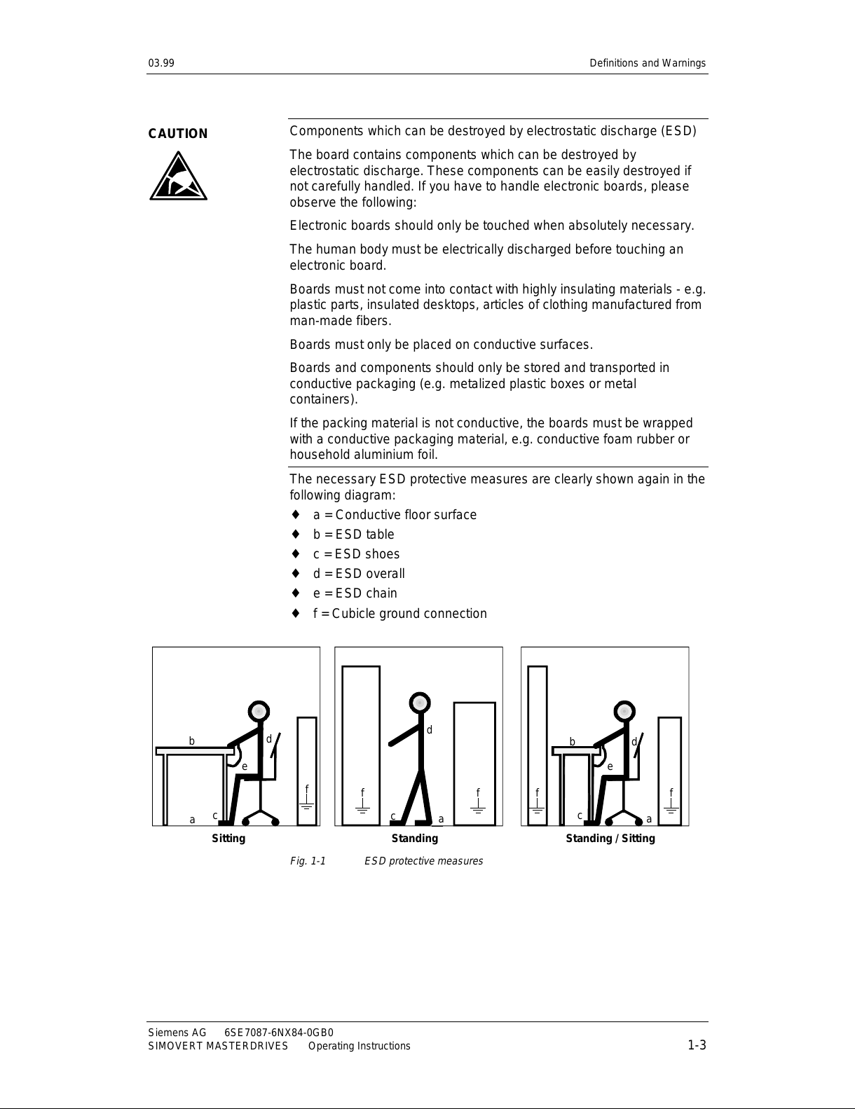
Components which can be destro yed by electros tat ic dischar g e (ESD)
The board contains components which can be destroyed by
electrostatic discharge. These components can be easily destroyed if
not carefully handled. If you have to handle elec tr onic boar ds , pleas e
observe the following:
Electronic boards should only be touched when absolutely necessary.
The human body must be electrically discharged before touching an
electronic board.
Boards must not come into contact with highly insulating materials - e.g.
plastic parts, insulated desktops, articles of clothing manufactured from
man-made fibers.
Boards must only be placed on conductive surfaces.
Boards and components should only be stored and transported in
conductive packaging (e.g. metalized plastic boxes or metal
containers).
If the packing material is not conductive, the boards must be wrapped
with a conductive packaging material, e.g. conductive foam rubber or
household aluminium foil.
The necessary ESD protective measures are clearly shown again in the
following diagram:
♦
a = Conductive floor surface
♦
b = ESD table
♦
c = ESD shoes
♦
d = ESD overall
♦
e = ESD chain
♦
f = Cubicle ground connection
StandingSitting Standing / Sitting
a
b
e
d
c
d
a
c
d
b
c
a
e
f
f
f f f
Fig. 1-1 ESD protective measures
CAUTION
All manuals and user guides at all-guides.com
Page 8

All manuals and user guides at all-guides.com
Page 9
03.99 Description
Siemens AG 6SE7087-6NX84-0GB0
SIMOVERT MASTERDRIVES Operating Instructions 2-1
2 Description
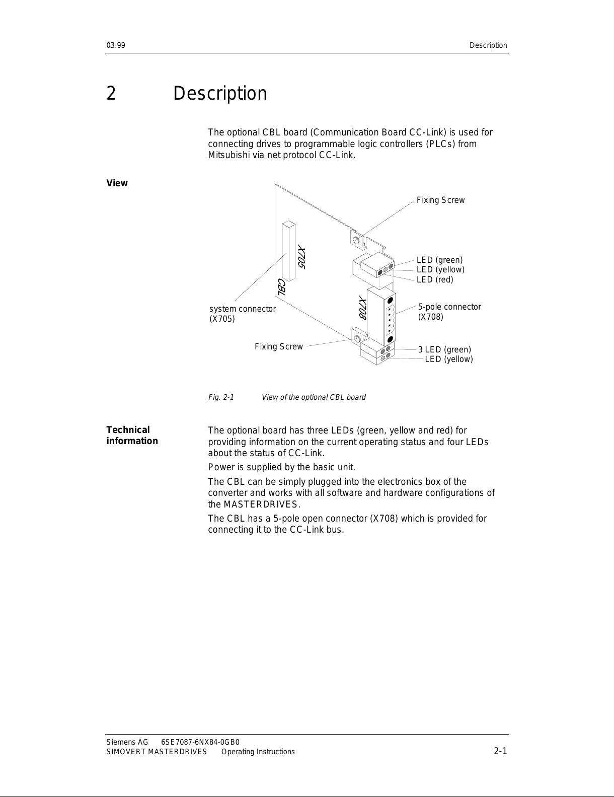
The optional CBL board (Communication Board CC-Link) is used for
connecting drives to programmable logic controllers (PLCs) from
Mitsubishi via net protocol CC-Link.
Fixing Screw
LED (green)
LED (yellow)
LED (red)
5-pole connector
(X708)
3 LED (green)
LED (yellow)
system connector
(X705)
Fixing Screw
Fig. 2-1 View of the optional CBL board
The optional board has three LEDs (green, yellow and red) for
providing information on the current operating status and four LEDs
about the status of CC-Link.
Power is supplied by the basic unit.
The CBL can be simply plugged into the electronics box of the
converter and works with all software and hardware configurations of
the MASTERDRIVES.
The CBL has a 5-pole open connector (X708) which is provided for
connecting it to the CC-Link bus.
View
Technical
information
All manuals and user guides at all-guides.com
Page 10
Description 03.99
6SE7087-6NX84-0GB0 Siemens AG
2-2 Operating Instructions SIMOVERT MASTERDRIVES
CC-Link is a field network developed by Mitsubishi Electric Corporation.
CC-Link is the abbreviation for "Control & Communication Link". From
programmable logic controllers (PLCs) you can communicate with
peripheral products like sensors, valves, inverters, etc.
At CC-Link there is one master and up to 64 slaves. The master has
address 0 and the slaves 1..64. CC-Link has a bus topology. The
communication speed can be set between 156 kBits/sec and 10
Mbits/sec. Depending on the transmission speed you have different
maximum bus length; see chapter 5 "Start-up of the CBL" (P711).
At CC-Link there are different data volumes and data types: bit control,
data control and messages (send/receive). These different data types
are realized with three types of devices:
♦
Remote IO device station
♦
Remote device station
♦
Intelligent device station
The different data volumes are realized at the remote device station by
occupying multiple (up to 4) slave addresses.
With the communication board CBL you can communicate from
Mitsubishi PLCs to SIMOVERT MASTERDRIVES systems. You can
control drives by setpoints of frequency or torque.
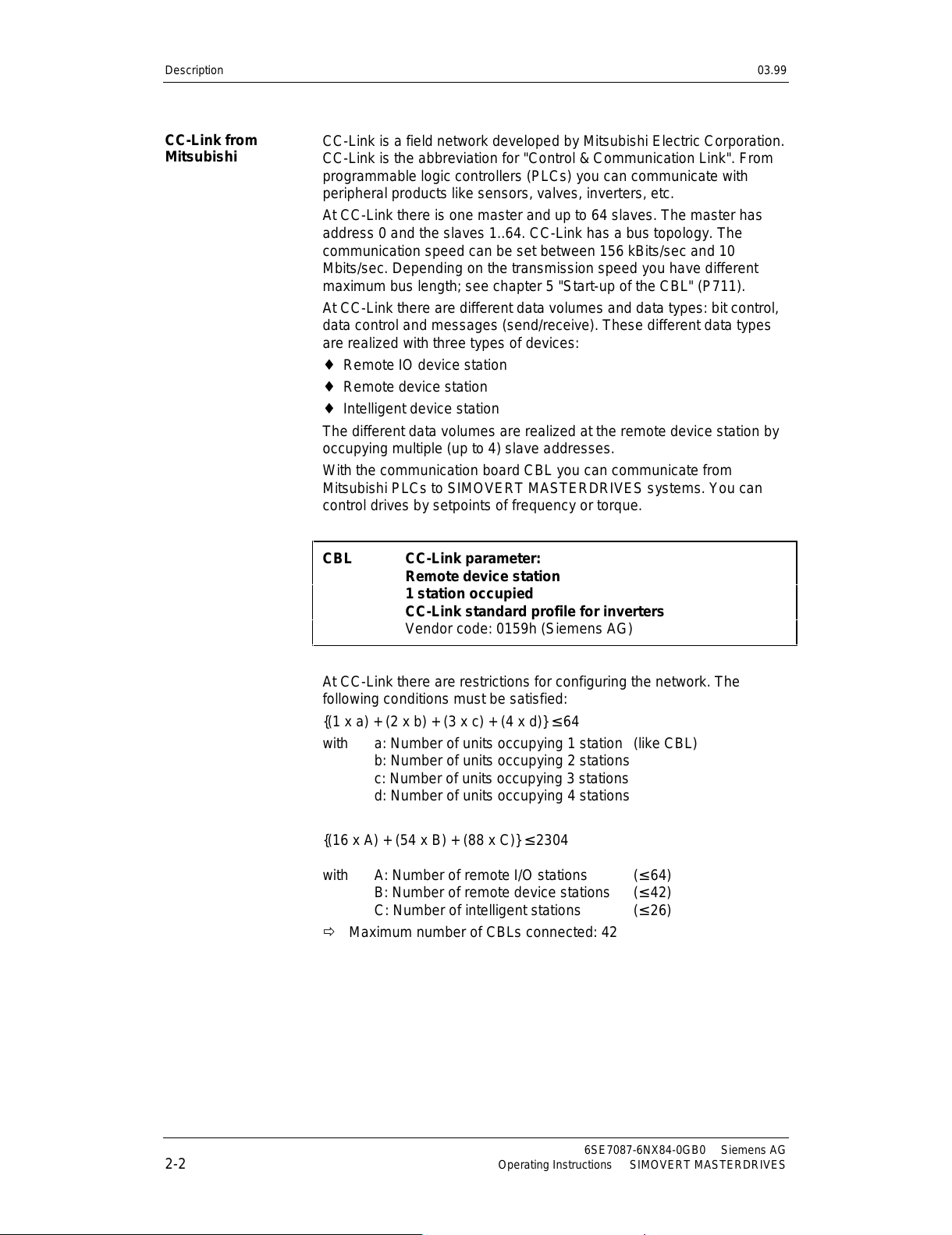
CBL CC-Link parameter:
Remote device station
1 station occupied
CC-Link standard profile for inverters
Vendor code: 0159h (Siemens AG)
At CC-Link there are restrictions for configuring the network. The
following conditions must be satisfied:
{(1 x a) + (2 x b) + (3 x c) + (4 x d)} ≤ 64
with a: Number of units occupying 1 station (like CBL)
b: Number of units occupying 2 stations
c: Number of units occupying 3 stations
d: Number of units occupying 4 stations
{(16 x A) + (54 x B) + (88 x C)} ≤ 2304
with A: Number of remote I/O stations (≤ 64)
B: Number of remote device stations (≤ 42)
C: Number of intelligent stations (≤ 26)
Õ Maximum number of CBLs connected: 42
CC-Link from
Mitsubishi
All manuals and user guides at all-guides.com
Page 11
03.99 Description
Siemens AG 6SE7087-6NX84-0GB0
SIMOVERT MASTERDRIVES Operating Instructions 2-3
2.1 Mounting methods / CBL slots
The CBL can be directly mounted into Compact PLUS units. For all
other frame sizes, it is mounted on the CUMC or CUVC or connected in
the electronics box with an adapter board.
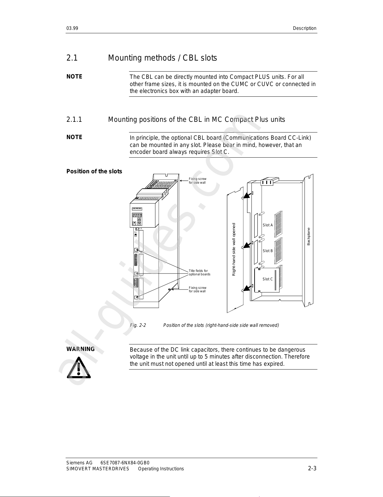
2.1.1 Mounting positions of the CBL in MC Compact Plus units
In principle, the optional CBL board (Communications Board CC-Link)
can be mounted in any slot. Please bear in mind, however, that an
encoder board always requires Slot C.
SIEM ENS
A
S1
BX101
CX103
Fixing screw
for side wall
Fixing screw
for side wall
Title fields for
optional boards
Slot A
Slot B
Slot C
Backplane
Right-hand side wall opened
Fig. 2-2 Position of the slots (right-hand-side side wall removed)
Because of the DC link capacitors, there continues to be dangerous
voltage in the unit until up to 5 minutes after disconnection. Therefore
the unit must not opened until at least this time has expired.
NOTE
NOTE
Position of the slots
WARNING
All manuals and user guides at all-guides.com
all-guides.com
Page 12
Description 03.99
6SE7087-6NX84-0GB0 Siemens AG
2-4 Operating Instructions SIMOVERT MASTERDRIVES
2.1.2 Mounting positions of the CBL in Compact and chassis units of
MASTERDRIVES VectorControl (CUVC) and MASTERDRIVES
(CUMC)
In the electronics box of the compact-type and chassis-type converters
and inverters, there are up to six slots available for installing an optional
board. The slots are marked with the letters A to G. Slot B is not
present in these types of unit; it is used in Compact PLUS units.
If you wish to use Slots D to G, you must first mount the LBA (Local
Bus Adapter) and the corresponding adapter board.
In principle, you can operate the optional CBL board (Communication
Board CC-Link) in any slot. Please bear in mind, however, that an
encoder board always needs Slot C and that the LBA requires the slots
to be used in a particular sequence.
The CBL can be mounted on the adapter board in both slots, i.e. TOP
and/or BOTTOM.
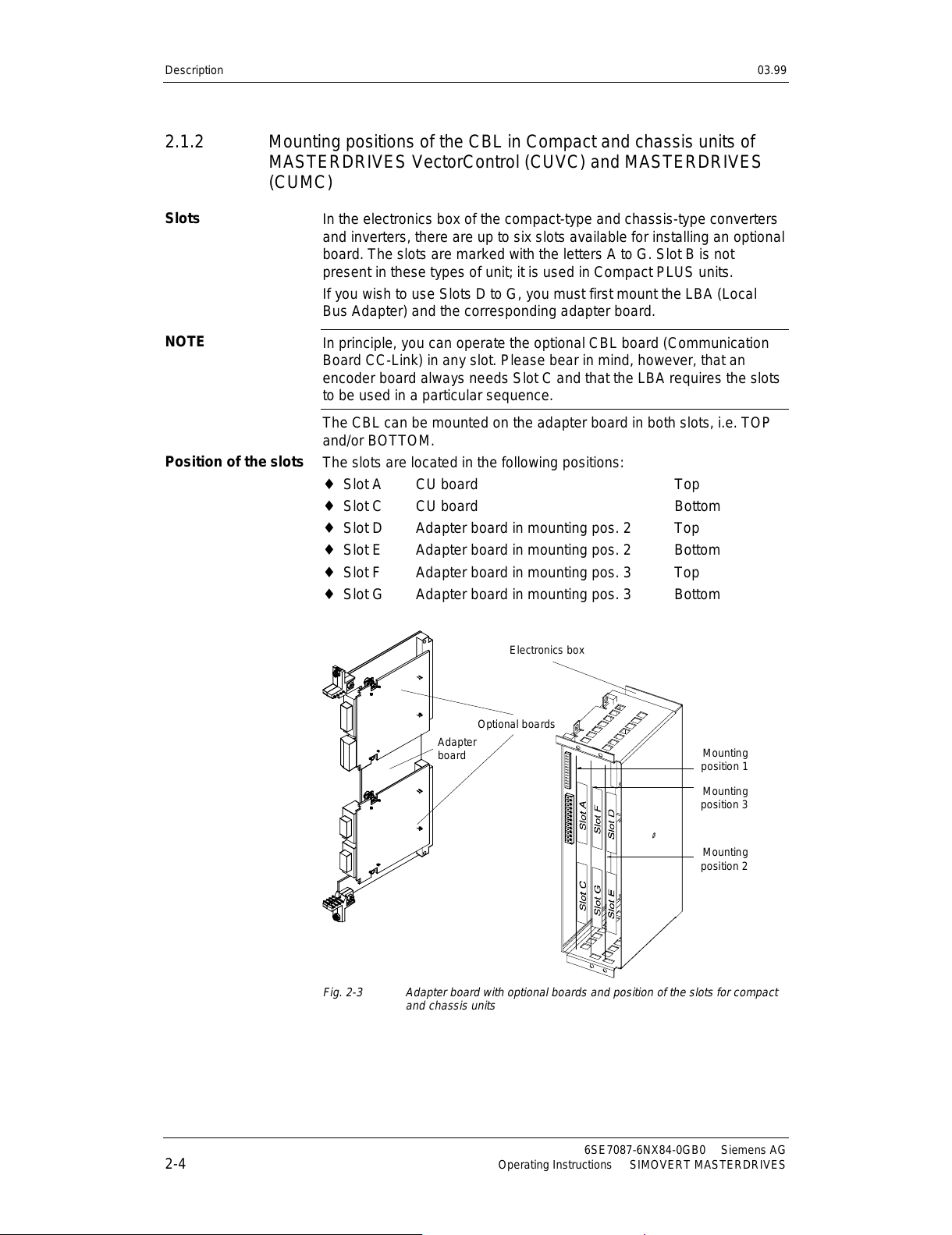
The slots are located in the following positions:
♦
Slot A CU board Top
♦
Slot C CU board Bottom
♦
Slot D Adapter board in mounting pos. 2 Top
♦
Slot E Adapter board in mounting pos. 2 Bottom
♦
Slot F Adapter board in mounting pos. 3 Top
♦
Slot G Adapter board in mounting pos. 3 Bottom
Adapter
board
Optional boards
Electronics box
Mounting
position 1
Mounting
position 2
Mounting
position 3
Fig. 2-3 Adapter board with optional boards and position of the slots for compact
and chassis units
Slots
NOTE
Position of the slots
All manuals and user guides at all-guides.com
Page 13
03.99 Description
Siemens AG 6SE7087-6NX84-0GB0
SIMOVERT MASTERDRIVES Operating Instructions 2-5
Because of the DC link capacitors, there continues to be dangerous
voltage in the unit until up to 5 minutes after disconnection. Therefore
the unit must not opened until at least this time has expired.
Due to the technical structure of the LBA, certain sequences are
stipulated for use of the slots.
If only one adapter board with optional boards is insert ed into the
electronics box, it always must be plugged into mounting position 2.
If a T100 / T300 or T400 technology board is plugged into the
electronics box in addition to the adapter board with CBL, the
technology board must be plugged into mounting position 2. In this
case, the CBL is plugged into mounting position 3.
WARNING
All manuals and user guides at all-guides.com
Page 14

All manuals and user guides at all-guides.com
Page 15
03.99 Connecting
Siemens AG 6SE7087-6NX84-0GB0
SIMOVERT MASTERDRIVES Operating Instructions 3-1
3 Connecting
The SIMOVERT MASTERDRIVES are operated with high voltages.
Any work on the unit may only be carried out by qualified personnel.
If this warning is ignored, serious injury or considerable damage to
property can occur as a consequence.
Because of the DC link capacitors, there continues to be dangerous
voltage in the unit until up to 5 minutes after disconnection. Therefore
the unit must not opened until at least this time has expired.
Even when the motor is at a standstill, the power terminals and the
control terminals can carry voltage. During work on the converter, it has
to be disconnected from the power supply.
When handling the opened converter, it must be kept in mind that live
components are exposed.
The CBL contains electrostatically sensitive components. These
components can very easily be destroyed by improper handling.
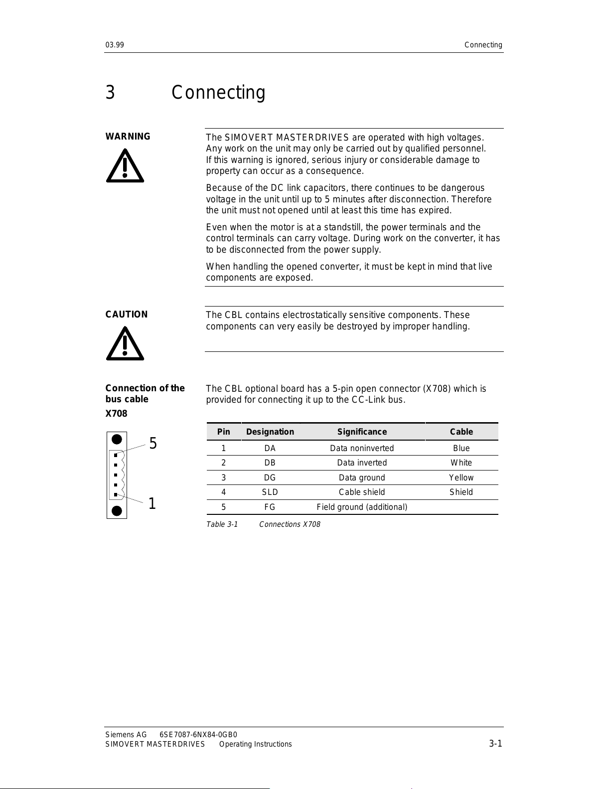
The CBL optional board has a 5-pin open connector (X708) which is
provided for connecting it up to the CC-Link bus.
Pin Designation Significance Cable
1 DA Data noninverted Blue
2 DB Data inverted White
3 DG Data ground Yellow
4 SLD C able shi eld Shield
5 FG Field ground (additional)
Table 3-1 Connections X708
WARNING
CAUTION
Connection of the
bus cable
X708
1
5
All manuals and user guides at all-guides.com
Page 16
Connecting 03.99
6SE7087-6NX84-0GB0 Siemens AG
3-2 Operating Instructions SIMOVERT MASTERDRIVES
Blue
White Yellow
Shielding
DA
DB
DG
Sheath
5 pole terminal clamp
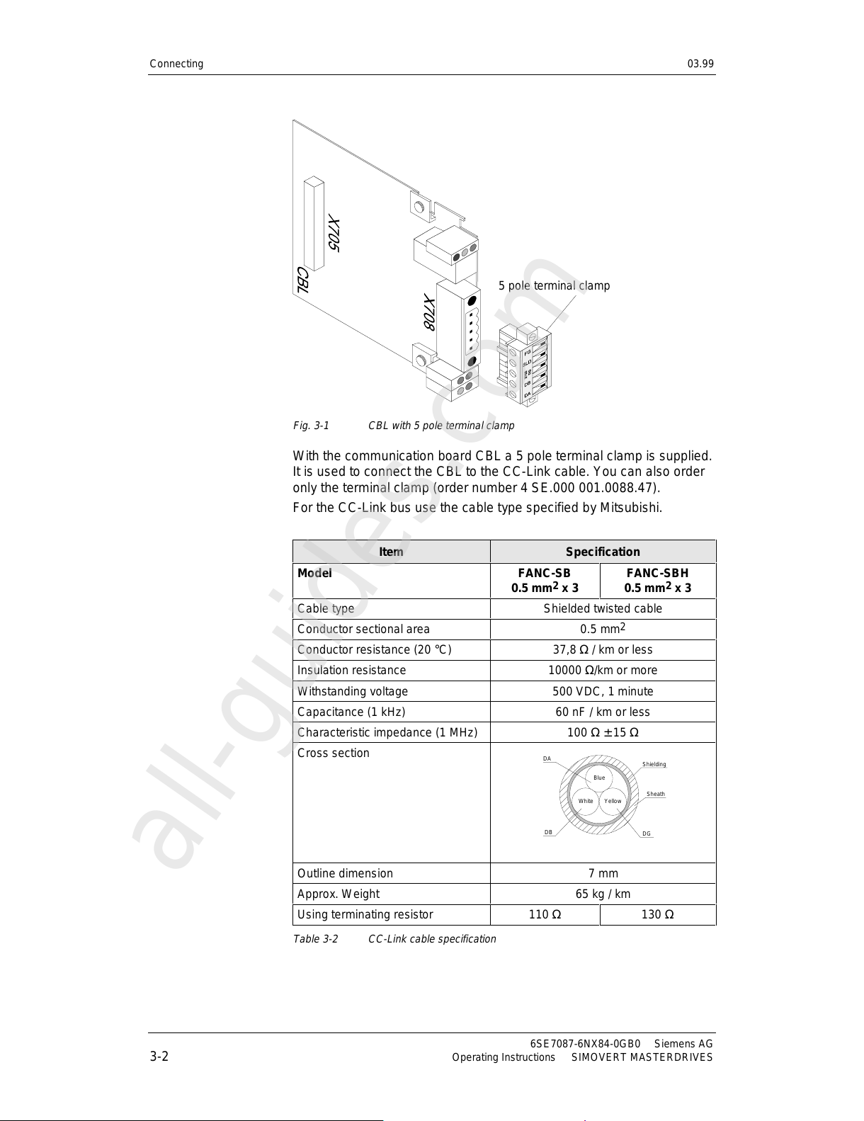
Fig. 3-1 CBL with 5 pole terminal clamp
With the communication board CBL a 5 pole terminal clamp is supplied.
It is used to connect the CBL to the CC-Link cable. You can also order
only the terminal clamp (order number 4 SE.000 001.0088.47).
For the CC-Link bus use the cable type specified by Mitsubishi.
Item Specification
Model FANC-SB
0.5 mm
2
x 3
FANC-SBH
0.5 mm2 x 3
Cable type Shielded twisted cable
Conductor sectional area 0.5 mm
2
Conductor resistance (20 °C) 37,8 Ω / km or less
Insulation resistance 10000 Ω/km or more
Withstanding voltage 500 VDC, 1 minute
Capacitance (1 kHz) 60 nF / km or less
Characteristic impedance (1 MHz) 100 Ω ± 15 Ω
Cross section
Outline dimension 7 mm
Approx. Weight 65 kg / km
Using terminating resistor 110 Ω 130 Ω
Table 3-2 CC-Link cable specification
All manuals and user guides at all-guides.com
all-guides.com
Page 17
03.99 Connecting
Siemens AG 6SE7087-6NX84-0GB0
SIMOVERT MASTERDRIVES Operating Instructions 3-3
Mitsubishi specifies a maximum cable length depending on the data
transfer rate. For more detailed information refer to documentation of
CC-Link by Mitsubishi.
Data transfer rate Total bus distance
10 MBit/s 100 m
5 Mbit/s 150 m
2.5 MBit/s 200 m
625 kBit/s 600 m
156 kBit/s 1200 m
Table 3-3 Cable length in relation to the baud rate
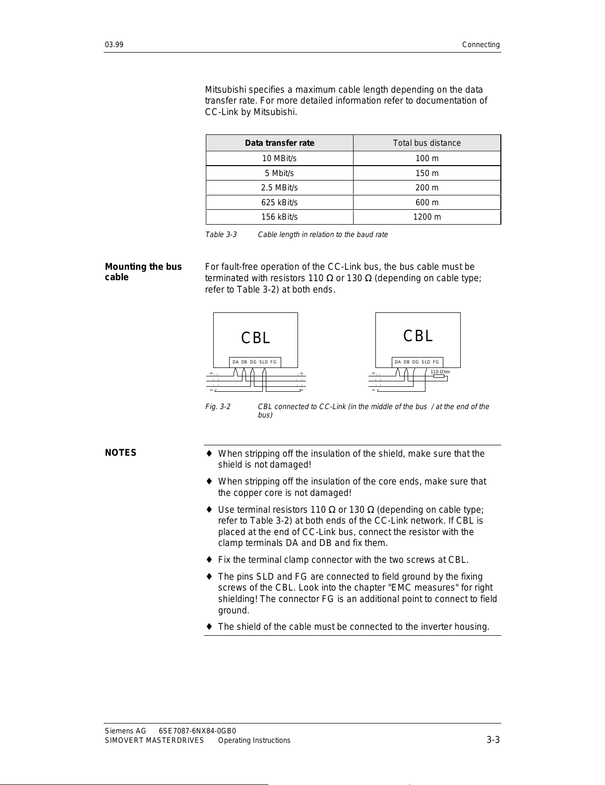
For fault-free operation of the CC-Link bus, the bus cable must be
terminated with resistors 110 Ω or 130 Ω (depending on cable type;
refer to Table 3-2) at both ends.
DA DB DG SLD FG
CBL
DA DB DG SLD FG
CBL
110 Ohm
Fig. 3-2 CBL connected to CC-Link (in the middle of the bus / at the end of the
bus)
♦
When stripping off the insulation of the shield, make sure that the
shield is not damaged!
♦
When stripping off the insulation of the core ends, make sure that
the copper core is not damaged!
♦
Use terminal resistors 110 Ω or 130 Ω (depending on cable type;
refer to Table 3-2) at both ends of the CC-Link network. If CBL is
placed at the end of CC-Link bus, connect the resistor with the
clamp terminals DA and DB and fix them.
♦
Fix the terminal clamp connector with the two screws at CBL.
♦
The pins SLD and FG are connected to field ground by the fixing
screws of the CBL. Look into the chapter "EMC measures" for right
shielding! The connector FG is an additional point to connect to field
ground.
♦ The shield of the cable must be connected to the inverter housing.
Mounting the bus
cable
NOTES
All manuals and user guides at all-guides.com
Page 18
Connecting 03.99
6SE7087-6NX84-0GB0 Siemens AG
3-4 Operating Instructions SIMOVERT MASTERDRIVES
3.1 EMC measures
For fault-free CC-Link operation, the following measures are necessary:
The bus cables must be twisted and shielded (refer to the definition of
Mitsubishi) and are to be routed separately from power cables, the
minimum clearance has to be 20 cm. The shield must be connected
through the largest possible surface area on both sides, i.e. the shield
of the bus cable between 2 converters must be connected to the
converter housing at both ends.
If bus and power cables intersect, they must cross at an angle of 90 °.
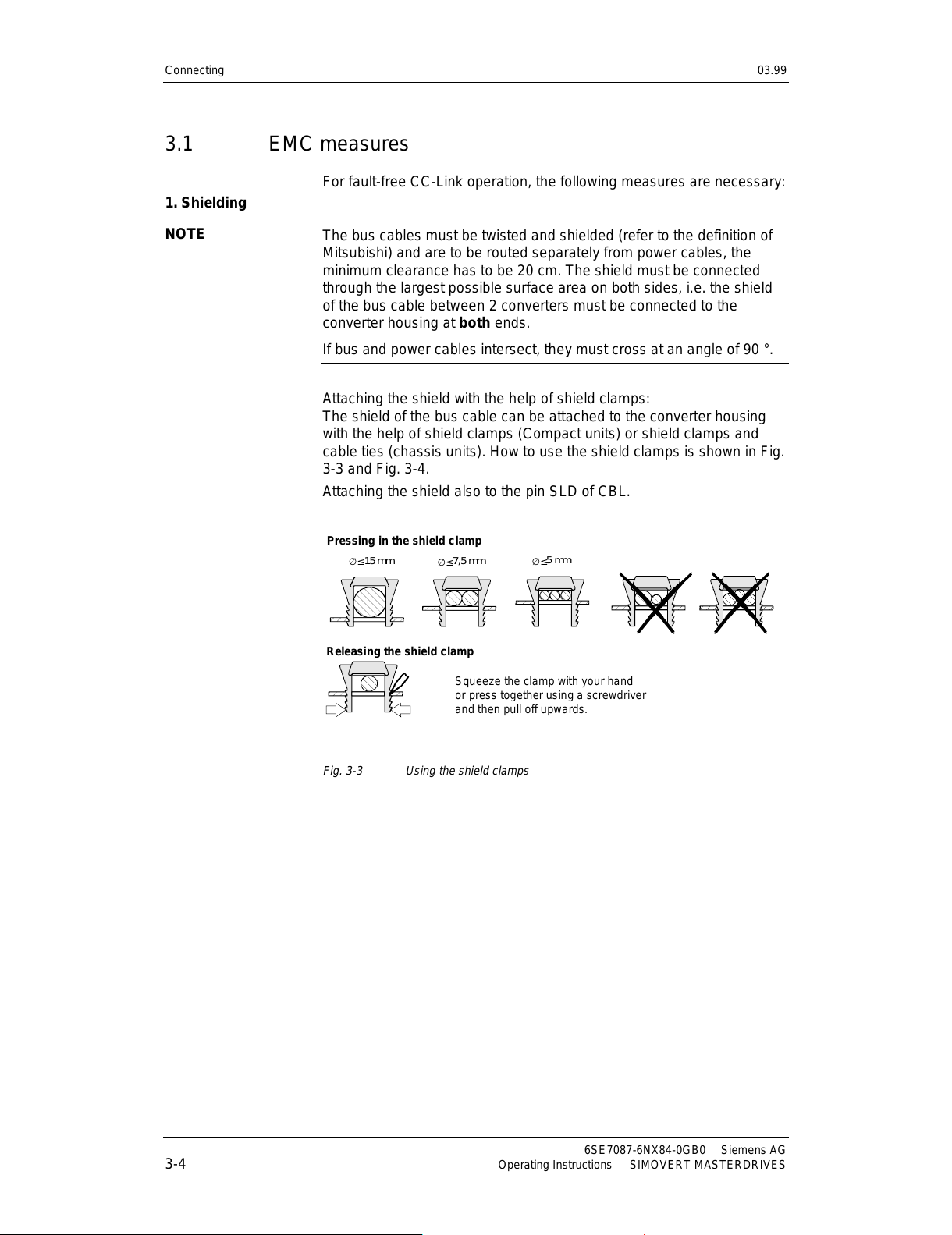
Attaching the shield with the help of shield clamps:
The shield of the bus cable can be attached to the converter housing
with the help of shield clamps (Compact units) or shield clamps and
cable ties (chassis units). How to use the shield clamps is shown in Fig.
3-3 and Fig. 3-4.
Attaching the shield also to the pin SLD of CBL.
∅ ≤
15 mm
∅ ≤
7,5 mm
∅ ≤
5 mm
Pressing in the shield clamp
Releasing the shield clamp
Squeeze the clamp with your hand
or press together using a screwdriver
and then pull off upwards.
Fig. 3-3 Using the shield clamps
1. Shielding
NOTE
All manuals and user guides at all-guides.com
Page 19
03.99 Connecting
Siemens AG 6SE7087-6NX84-0GB0
SIMOVERT MASTERDRIVES Operating Instructions 3-5
Type of co nstruc tion
E-box
E-box
E-box
E-box
SIEMENS
X100
A
S1
BX101
CX103
Slot A
Slot B
Slot C
Shield connection
for control cables
Shield cove r
for motor cable
−
Compact and chassis units Compact PLUS
Shield connecting points
A
B
Type of co nstruc tion
D
C
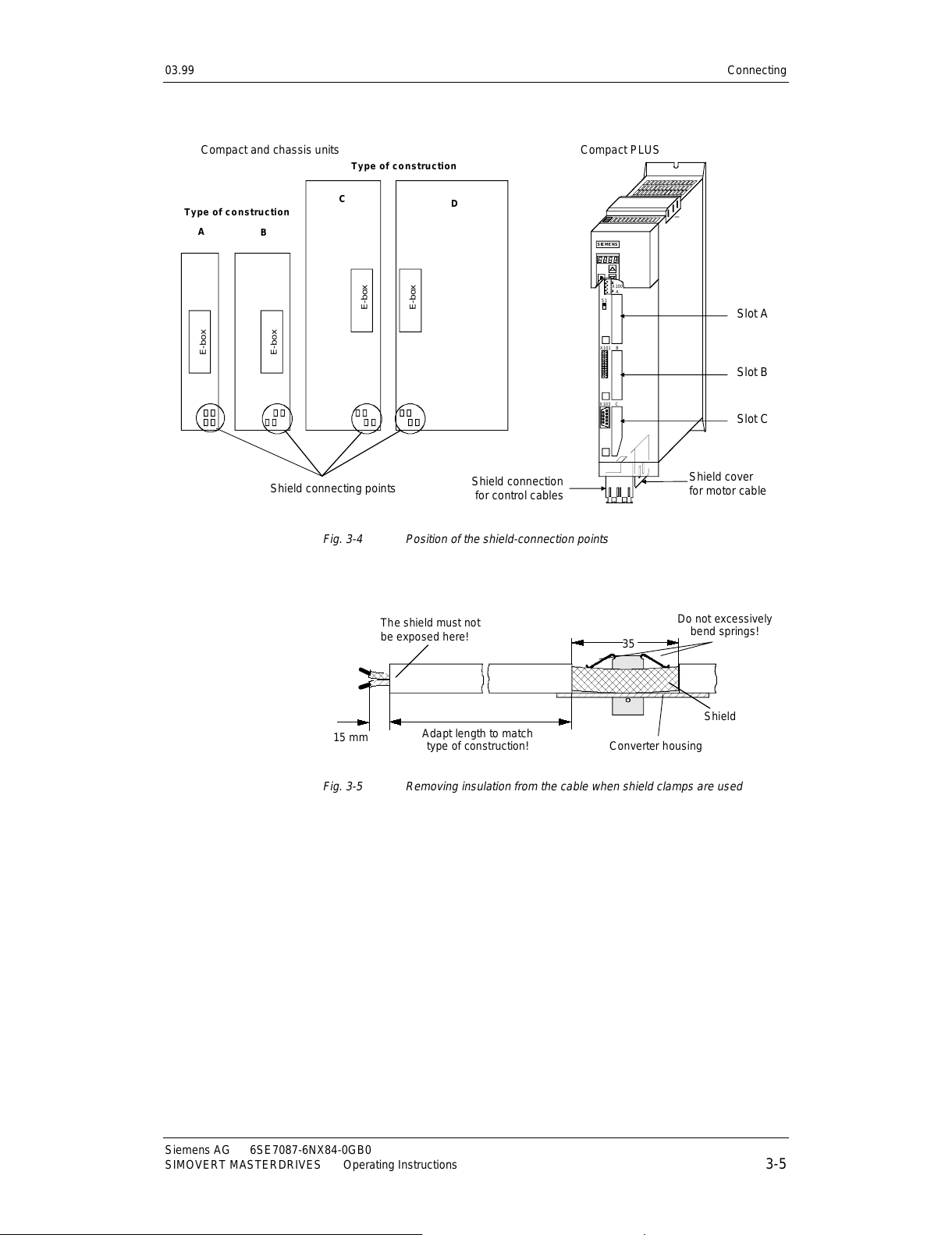
Fig. 3-4 Position of the shield-connection points
The shield must not
be exposed here!
Do not excessively
bend springs!
35
Shield
Adapt length to match
type of construction!
Convert er housing
15 mm
Fig. 3-5 Removing insulation from the cable when shield clamps are used
All manuals and user guides at all-guides.com
Page 20
Connecting 03.99
6SE7087-6NX84-0GB0 Siemens AG
3-6 Operating Instructions SIMOVERT MASTERDRIVES
Please avoid differences in potential (e.g. due to different supply levels)
between the converters and the CC-Link master:
♦
Use equipotential bonding cables:
•
16 mm
2
Cu for equipotential bonding cables up to 200 m
•
25 mm
2
Cu for equipotential bonding cables over 200 m
♦
Lay the equipotential bonding cables so that there is the smallest
possible surface area between the equipotential bonding cable and
signal cables.
♦
Connect equipotential bonding conductors to the earth/protective
conductor through the largest possible surface area.
Please comply with the following instructions when laying cables:
♦
Do not lay bus cables (signal cables) directly parallel to power
cables.
♦
Lay signal cables and the associated equipotential bonding cables
with the lowest possible distance between them and on the shortest
routes.
♦
Lay power cables and signal cables in separate cable ducts.
♦
Attach shields through a large surface area.
2. Equipotential
bonding
3. Laying cables
All manuals and user guides at all-guides.com
Page 21
03.99 Communication via CC-Link
Siemens AG 6SE7087-6NX84-0GB0
SIMOVERT MASTERDRIVES Operating Instructions 4-1
4 Communication via CC-Link
4.1 CC-Link profile of SIMOVERT MASTERDRIVES
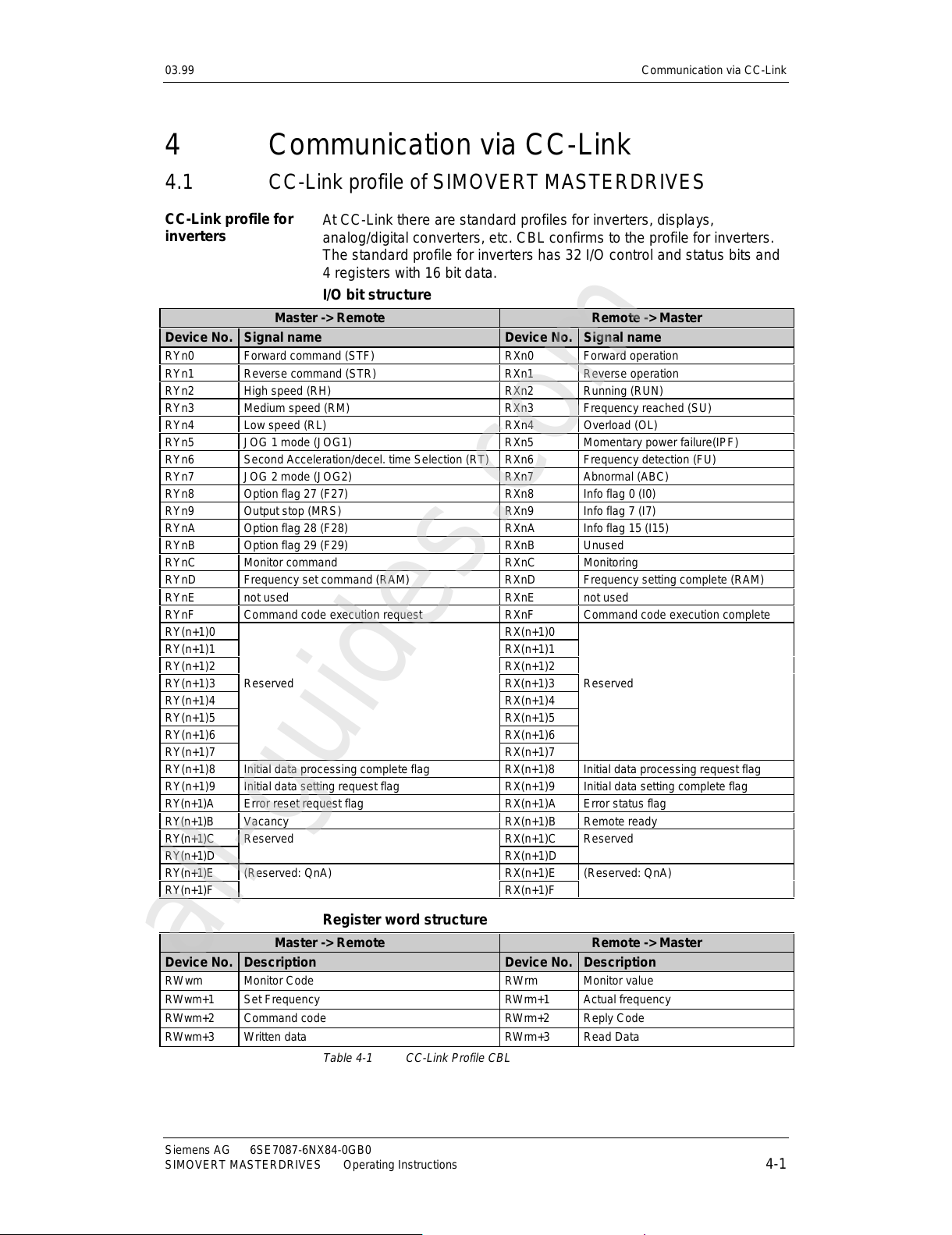
At CC-Link there are standard profiles for inverters, displays,
analog/digital converters, etc. CBL confirms to the profile for inverters.
The standard profile for inverters has 32 I/O control and status bits and
4 registers with 16 bit data.
I/O bit structure
Master -> Remote Remote -> Master
Device No. Signal name Device No. Signal name
RYn0 Forward command (STF) RXn0 Forward operation
RYn1 Reverse command (STR) RXn1 Reverse operation
RYn2 High speed (RH) RXn2 Running (RUN)
RYn3 Medium speed (RM) RXn3 Frequency reached (SU)
RYn4 Low speed (RL) RXn4 Overload (OL)
RYn5 JOG 1 mode (JOG1) RXn5 Momentary power failure(IPF)
RYn6 Second Acceleration/decel. time Selection (RT) RXn6 Frequency detection (FU)
RYn7 JOG 2 mode (JOG2) RXn7 Abnormal (ABC)
RYn8 Option flag 27 (F27) RXn8 Info flag 0 (I0)
RYn9 Output stop (MRS) RXn9 Info flag 7 (I7)
RYnA Option flag 28 (F28) RXnA Info flag 15 (I15)
RYnB Option flag 29 (F29) RXnB Unused
RYnC Monitor command RXnC Monitoring
RYnD Frequency set command (RAM) RXnD Frequency setting complete (RAM)
RYnE not used RXnE not used
RYnF Command code execution request RXnF Comm and code executi on compl ete
RY(n+1)0 RX(n+1)0
RY(n+1)1 RX(n+1)1
RY(n+1)2 RX(n+1)2
RY(n+1)3 Reserved RX(n+1)3 Reserved
RY(n+1)4 RX(n+1)4
RY(n+1)5 RX(n+1)5
RY(n+1)6 RX(n+1)6
RY(n+1)7 RX(n+1)7
RY(n+1)8 Initial data processing complete flag RX(n+1)8 Initial data processing request flag
RY(n+1)9 Initial data setting request flag RX(n+1)9 Initial data setting complete flag
RY(n+1)A Error reset request flag RX(n+1)A Error status flag
RY(n+1)B Vacancy RX(n+1)B Remote ready
RY(n+1)C Reserved RX(n+1)C Reserved
RY(n+1)D RX(n+1)D
RY(n+1)E (Reserved: QnA) RX(n+1)E (Reserved: QnA)
RY(n+1)F RX(n+1)F
Register word structure
Master -> Remote Remote -> Master
Device No. Description Device No. Description
RWwm Monitor Code RWrm Monitor value
RWwm+1 Set Frequency RWrm+1 Actual frequency
RWwm+2 Command code RWrm+2 Reply Code
RWwm+3 Written data RWrm+3 Read Data
Table 4-1 CC-Link Profile CBL
CC-Link profile for
inverters
All manuals and user guides at all-guides.com
all-guides.com
Page 22
Communication via CC-Link 03.99
6SE7087-6NX84-0GB0 Siemens AG
4-2 Operating Instructions SIMOVERT MASTERDRIVES
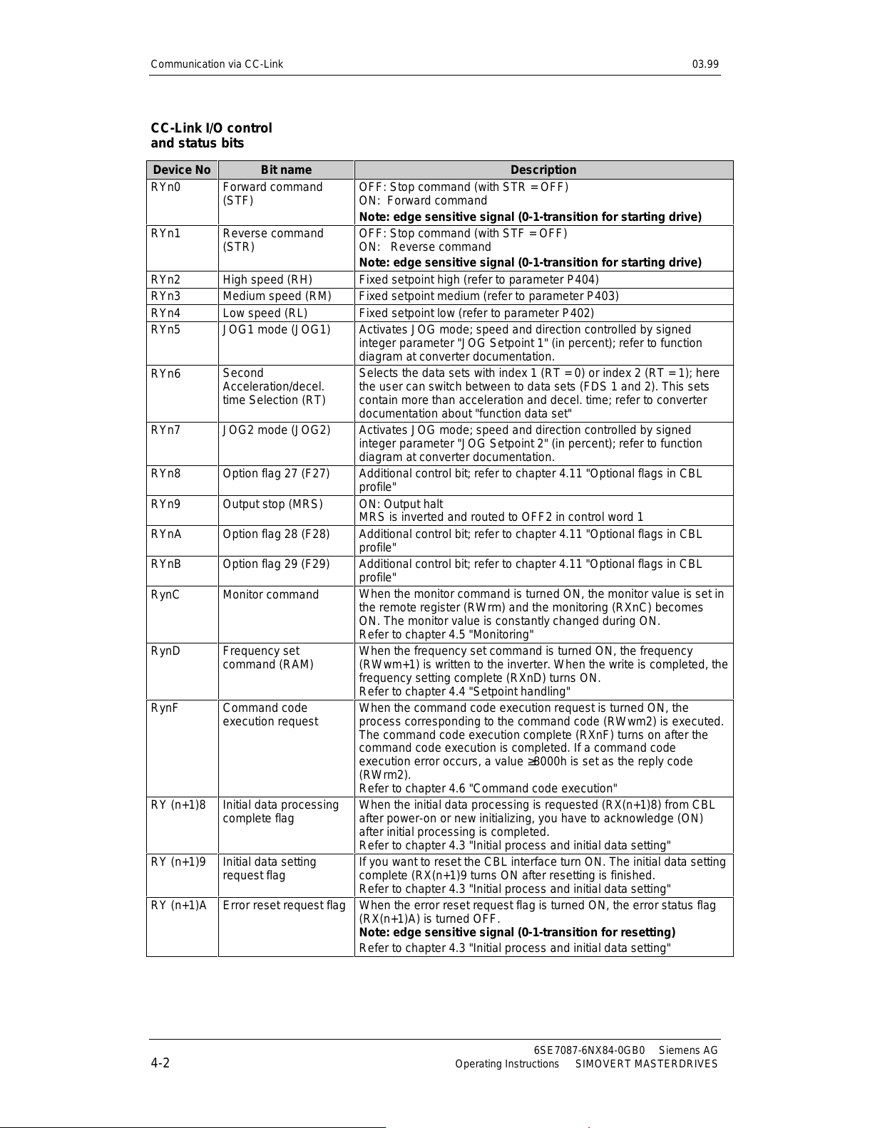
Device No Bit name Description
RYn0 Forward command
(STF)
OFF: Stop command (with STR = OFF)
ON: Forward command
Note: edge sensitive signal (0-1-transition for starting drive)
RYn1
Reverse command
(STR)
OFF: Stop command (with STF = OFF)
ON: Reverse command
Note: edge sensitive signal (0-1-transition for starting drive)
RYn2 High speed (RH) Fixed setpoint high (refer to parameter P404)
RYn3 Medium speed (RM) Fixed setpoint medium (refer to parameter P403)
RYn4 Low speed (RL) Fixed setpoint low (refer to parameter P402)
RYn5 JOG1 mode (JOG1)
Activates JOG mode; speed and direction controlled by signed
integer parameter "JOG Setpoint 1" (in percent); refer to function
diagram at converter documentation.
RYn6
Second
Acceleration/decel.
time Selection (RT)
Selects the data sets with index 1 (RT = 0) or index 2 (RT = 1); here
the user can switch between to data sets (FDS 1 and 2). This sets
contain more than acceleration and decel. time; refer to converter
documentation about "function data set"
RYn7 JOG2 mode (JOG2)
Activates JOG mode; speed and direction controlled by signed
integer parameter "JOG Setpoint 2" (in percent); refer to function
diagram at converter documentation.
RYn8 Option flag 27 (F27)
Additional control bit; refer to chapter 4.11 "Optional flags in CBL
profile"
RYn9 Output stop (MRS) ON: Output halt
MRS is inverted and routed to OFF2 in control word 1
RYnA Option flag 28 (F28)
Additional control bit; refer to chapter 4.11 "Optional flags in CBL
profile"
RYnB Option flag 29 (F29) Additional control bit; refer to chapter 4.11 "Optional flags in CBL
profile"
RynC Monitor command
When the monitor command is turned ON, the monitor value is set in
the remote register (RWrm) and the monitoring (RXnC) becomes
ON. The monitor value is constantly changed during ON.
Refer to chapter 4.5 "Monitoring"
RynD
Frequency set
command (RAM)
When the frequency set command is turned ON, the frequency
(RWwm+1) is written to the inverter. When the write is completed, the
frequency setting complete (RXnD) turns ON.
Refer to chapter 4.4 "Setpoint handling"
RynF Command code
execution request
When the command code execution request is turned ON, the
process corresponding to the command code (RWwm2) is executed.
The command code execution complete (RXnF) turns on after the
command code execution is completed. If a command code
execution error occurs, a value ≥8000h is set as the reply code
(RWrm2).
Refer to chapter 4.6 "Command code execution"
RY (n+1)8 Initial data processing
complete flag
When the initial data processing is requested (RX(n+1)8) from CBL
after power-on or new initializing, you have to acknowledge (ON)
after initial processing is completed.
Refer to chapter 4.3 "Initial process and initial data setting"
RY (n+1)9 Initial data setting
request flag
If you want to reset the CBL interface turn ON. The initial data setting
complete (RX(n+1)9 turns ON after resetting is finished.
Refer to chapter 4.3 "Initial process and initial data setting"
RY (n+1)A Error reset request flag When the error reset request flag is turned ON, the error status flag
(RX(n+1)A) is turned OFF.
Note: edge sensitive signal (0-1-transition for resetting)
Refer to chapter 4.3 "Initial process and initial data setting"
CC-Link I/O control
and status bits
All manuals and user guides at all-guides.com
Page 23
03.99 Communication via CC-Link
Siemens AG 6SE7087-6NX84-0GB0
SIMOVERT MASTERDRIVES Operating Instructions 4-3
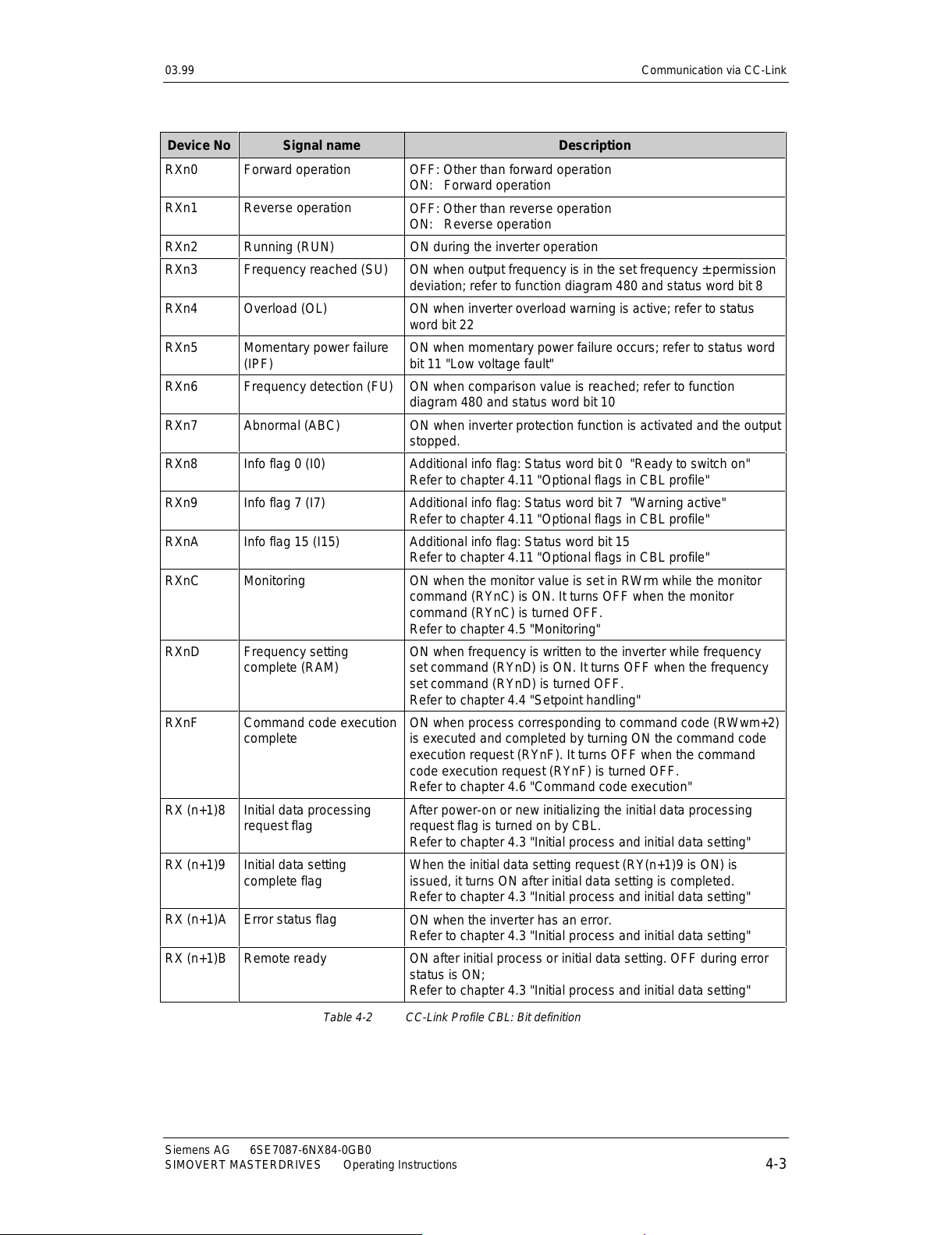
Device No Signal name Description
RXn0 Forward operation OFF: Other than forward operation
ON: Forward operation
RXn1 Reverse operation
OFF: Other than reverse operation
ON: Reverse operation
RXn2 Running (RUN) ON during the inverter operation
RXn3 Frequency reached (SU)
ON when output frequency is in the set frequency ± permission
deviation; refer to function diagram 480 and status word bit 8
RXn4 Overload (OL)
ON when inverter overload warning is active; refer to status
word bit 22
RXn5 Momentary power failure
(IPF)
ON when momentary power failure occurs; refer to status word
bit 11 "Low voltage fault"
RXn6 Frequency detection (FU) ON when comparison value is reached; refer to function
diagram 480 and status word bit 10
RXn7 Abnormal (ABC) ON when inverter protection function is activated and the output
stopped.
RXn8 Info flag 0 (I0) Additional info flag: Status word bit 0 "Ready to switch on"
Refer to chapter 4.11 "Optional flags in CBL profile"
RXn9 Info flag 7 (I7)
Additional info flag: Status word bit 7 "Warning active"
Refer to chapter 4.11 "Optional flags in CBL profile"
RXnA Info flag 15 (I15)
Additional info flag: Status word bit 15
Refer to chapter 4.11 "Optional flags in CBL profile"
RXnC Monitoring ON when the monitor value is set in RWrm while the monitor
command (RYnC) is ON. It turns OFF when the monitor
command (RYnC) is turned OFF.
Refer to chapter 4.5 "Monitoring"
RXnD
Frequency setting
complete (RAM)
ON when frequency is written to the inverter while frequency
set command (RYnD) is ON. It turns OFF when the frequency
set command (RYnD) is turned OFF.
Refer to chapter 4.4 "Setpoint handling"
RXnF
Command code execution
complete
ON when process corresponding to command code (RWwm+2)
is executed and completed by turning ON the command code
execution request (RYnF). It turns OFF when the command
code execution request (RYnF) is turned OFF.
Refer to chapter 4.6 "Command code execution"
RX (n+1)8
Initial data processing
request flag
After power-on or new initializing the initial data processing
request flag is turned on by CBL.
Refer to chapter 4.3 "Initial process and initial data setting"
RX (n+1)9 Initial data setting
complete flag
When the initial data setting request (RY(n+1)9 is ON) is
issued, it turns ON after initial data setting is completed.
Refer to chapter 4.3 "Initial process and initial data setting"
RX (n+1)A Error status flag
ON when the inverter has an error.
Refer to chapter 4.3 "Initial process and initial data setting"
RX (n+1)B Remote ready ON after initial process or initial data setting. OFF during error
status is ON;
Refer to chapter 4.3 "Initial process and initial data setting"
Table 4-2 CC-Link Profile CBL: Bit definition
All manuals and user guides at all-guides.com
Page 24
Communication via CC-Link 03.99
6SE7087-6NX84-0GB0 Siemens AG
4-4 Operating Instructions SIMOVERT MASTERDRIVES
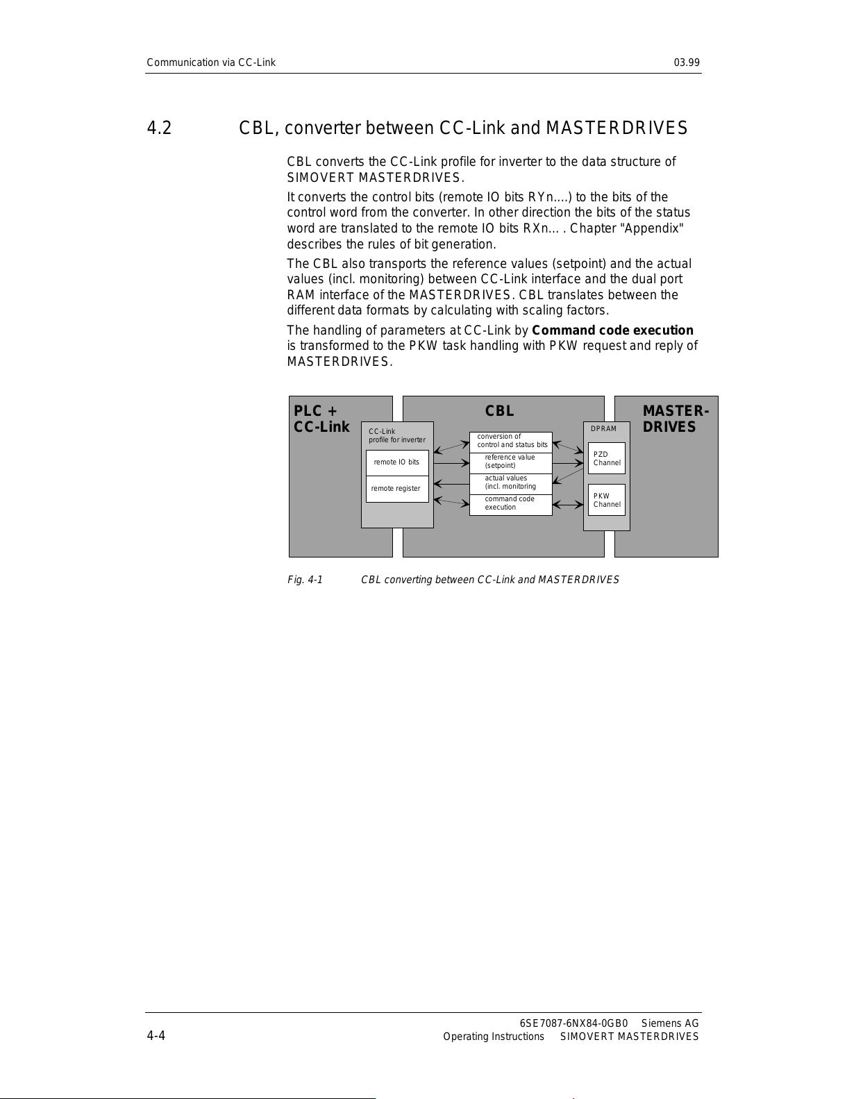
4.2 CBL, converter between CC-Link and MASTERDRIVES
CBL converts the CC-Link profile for inverter to the data structure of
SIMOVERT MASTERDRIVES.
It converts the control bits (remote IO bits RYn....) to the bits of the
control word from the converter. In other direction the bits of the status
word are translated to the remote IO bits RXn... . Chapter "Appendix"
describes the rules of bit generation.
The CBL also transports the reference values (setpoint) and the actual
values (incl. monitoring) between CC-Link interface and the dual port
RAM interface of the MASTERDRIVES. CBL translates between the
different data formats by calculating with scaling factors.
The handling of parameters at CC-Link by Command
code execution
is transformed to the PKW task handling with PKW request and reply of
MASTERDRIVES.
remote IO bits
remote register
reference value
(setpoi nt)
actual values
(incl. monitoring
command code
execution
conversion of
control and status bits
PZD
Channel
PKW
Channel
DPRAM
CC-Link
profile for inverter
CBLPLC +
CC-Link
MASTER-
DRIVES
Fig. 4-1 CBL converting between CC-Link and MASTERDRIVES
All manuals and user guides at all-guides.com
Page 25
03.99 Communication via CC-Link
Siemens AG 6SE7087-6NX84-0GB0
SIMOVERT MASTERDRIVES Operating Instructions 4-5
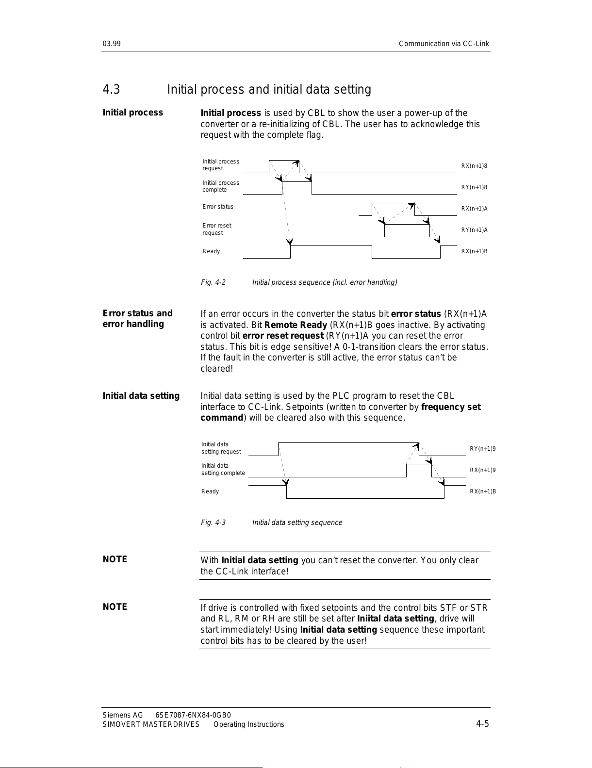
4.3 Initial process and initial data setting
Initial process is used by CBL to show the user a power-up of the
converter or a re-initializing of CBL. The user has to acknowledge this
request with the complete flag.
RX(n+1)8
RY(n+1)8
RX(n+1)A
RY(n+1)A
RX(n+1)B
Initial process
request
Initial process
complete
Error status
Error reset
request
Ready
Fig. 4-2 Initial process sequence (incl. error handling)
If an error occurs in the converter the status bit error status (RX(n+1)A
is activated. Bit Remote Ready
(RX(n+1)B goes inactive. By activating
control bit error reset request
(RY(n+1)A you can reset the error
status. This bit is edge sensitive! A 0-1-transition clears the error status.
If the fault in the converter is still active, the error status can’t be
cleared!
Initial data setting is used by the PLC program to reset the CBL
interface to CC-Link. Setpoints (written to converter by frequency set
command) will be cleared also with this sequence.
RY(n+1)9
RX(n+1)9
RX(n+1)B
Initial d ata
setting request
Initial d ata
setting complete
Ready
Fig. 4-3 Initial data setting sequence
With Initial data setting you can’t reset the converter. You only clear
the CC-Link interface!
If drive is controlled with fixed setpoints and the control bits STF or STR
and RL, RM or RH are still be set after Iniital data setting, drive will
start immediately! Using Initial data setting sequence these important
control bits has to be cleared by the user!
Initial process
Error status and
error handling
Initial data setting
NOTE
NOTE
All manuals and user guides at all-guides.com
Page 26

Communication via CC-Link 03.99
6SE7087-6NX84-0GB0 Siemens AG
4-6 Operating Instructions SIMOVERT MASTERDRIVES
4.4 Setpoint handling
With SIMOVERT MASTERDRIVES converters there are several
possibilities to control a drive. In systems with CC-Link the drive can be
controlled by frequency setpoints or torque setpoints.
In the following sections there is the description how to handle the CBL
for controlling the drive with frequency setpoints. It is also valid for
torque control. Different handling is specially noted.
For more information about the possibilities of controlling and regulating
refer to converter documentation.
Giving setpoints from the PLC is possible in two ways:
♦
Working with fixed setpoints selected by control bits RL, RM and
RH. The fixed setpoints are stored in the fixed setpoint buffer of the
converter. They can parameterized from the panel of the converter
(PMU) or from PLC via CC-Link.
♦
Working with variable setpoints. They will be set with the frequency
set command
.
In the converter you can select (softwiring) one of the different sources
by the parameter P443 Source main setpoint. Refer to documentation
of converter; function diagram 316.
At regulation of torque use P486; refer to documentation of converter;
function diagram 320.
Example:
1) working with fixed setpoints RL, RM, RH:
=> P443 = 0040 Set frequency value from fix ed setpoi nt
buffer.
2) working with variable setpoints by frequency set command:
=> P443 = 3002 Set frequency value from first CBL to
Source main setpoint.
The different data formats for handling setpoints will be discribed in
chapter 4.9, "Data formats and data conversion".
The drive is started by activating control bit STF (RYn0: forward) or
STR (RYn1: reverse).
Regulation of
frequency or torque
Handling setpoints
All manuals and user guides at all-guides.com
all-guides.com
Page 27

03.99 Communication via CC-Link
Siemens AG 6SE7087-6NX84-0GB0
SIMOVERT MASTERDRIVES Operating Instructions 4-7
The frequency set command is initiated by the user. First he writes
the new setpoint into register set frequency (RWwm+1). Second he
activates the command with the control bit frequency set command
request (RYnD). After the CBL has written the new value to the
converter it acknowledges with frequency setting complete (RXnD).
new setpoint
RYnD
RWwm+1
RXnD
Frequency set
command request
Set frequency
Frequency setting
complete
Fig. 4-4 Frequency set command sequence
Check, that P443 Source main setpoint is set to communication board
PZD2 (first CBL => 3002)!
With RL, RM and RH you have 3 selectable fixed setpoints. You have
to parameterize the fixed setpoint buffer:
fixed setpoint (1) => P401 = 0000 "speed 0"
fixed setpoint (2) => P402 = xxxx "speed RL = xxxx"
fixed setpoint (3) => P403 = yyyy "speed RM = yyyy"
fixed setpoint (4) => P404 = zzzz "speed RH = zzzz"
After you have selected P443 = 0040 (Source main setpoint = fixed
setpoint buffer
)
you can control the speed by the control bits RL, RM
and RH. If you activate more than one bit of them, the lower speed has
the higher priority. The control bits JOG1 (RYn5) and JOG2 (Ryn7)
have higher priority than RL, RM and RH.
Priority: High <= JOG RL RM RH => Low
The JOG function can be activated by control bits JOG1 (RYn5) or
JOG2 (RYn7). JOG1 is assigned to "JOG setpoint 1" and JOG2 is
assigned to "JOG setpoint 2" of the converter; refer to its
documentation. The JOG setpoints in the converter are signed integer
values in percent; so speed and direction at JOG mode can be handled
by the user.
Don’t use STF and STR to control direction at JOG mode! Refer to
function diagrams of converter.
Frequency set
command
Fixed Setpoints with
RL, RM, RH
Controlling drive
with JOG1 and
JOG2
NOTE
All manuals and user guides at all-guides.com
Page 28

Communication via CC-Link 03.99
6SE7087-6NX84-0GB0 Siemens AG
4-8 Operating Instructions SIMOVERT MASTERDRIVES
4.5 Monitoring
With the monitoring command you can get a selectable actual value of
the process. First select one process value by writing selection number
into register monitor code (RWwm). Second you activate monitoring
with monitor command (RYnC). While this bit is active and the CBL
acknowledges with bit monitoring (RXnC), you get actual values in
register monitoring value (RWrm). You can change the monitor code
during monitoring command is active. But attention, you don’t know at
which time you get actual values from the new selected proc es s valu e!
Better you close the monitoring sequence, change the monitor code
and start a new sequence.
value a value a value b value b value b value bvalue a
monitor code a monitor code b
RYnC
RWwm
RXnC
RWrm
Monitor
command
Monitor
code
Monitoring
Monitor
value
Fig. 4-5 Monitor command sequence
If you write an invalid value into monitor code you get 0000 in monitor
value.
All manuals and user guides at all-guides.com
Page 29

03.99 Communication via CC-Link
Siemens AG 6SE7087-6NX84-0GB0
SIMOVERT MASTERDRIVES Operating Instructions 4-9
Monitoring
code
Description According
scaling
parameter
Precision of Mitsubishi
data format (1 digit)
0000h { Monitor value is 0000 } -
0001h Output frequency P717 0.01 Hz
0002h Output current P715 0.01 A
0003h Output voltage P716 0.1 V
0004h { Monitor value is 0000 } -
0005h Frequency set value P717 0.01 Hz
0006h Operating speed P718 1 rotation/min
0007h Motor torque - 0.1 %
000Fh Input terminal status - -
0010h Output terminal status - -
8001h Optional actual value 1 - MASTERDRIVES format
8002h Optional actual value 2 - MASTERDRIVES format
8003h Optional actual value 3 - MASTERDRIVES format
8004h Optional actual value 4 - MASTERDRIVES format
8005h Optional actual value 5 - MASTERDRIVES format
8006h Optional actual value 6 - MASTERDRIVES format
8007h Optional actual value 7 - MASTERDRIVES format
8008h Optional actual value 8 - MASTERDRIVES format
Table 4-3 Monitor code
The monitoring values can be read in Mi ts ubishi inverter data form at or
MASTERDRIVES data format (signed or unsigned); refer to chapter
4.9, "Data formats and data conversion". You select your data format
by the parameters P715 till P718.
The monitor values with monitor code
≤
0007 can be handled in both
data formats (depending on according scaling). The monitor values with
monitor code
≥
8001 are not converted. They have the original
MASTERDRIVES data format.
The monitor code 000Fh and 0010h shows some of the control bits
(remote IO bits):
Monitor Code 000Fh: input terminal status
Bit 15 Bit 9 Bit 8 Bit 7 Bit 6 Bit 5 Bit 4 Bit 3 Bit 2 Bit 1 Bit 0
0000.000 MRS JOG RH RM RL RT 0 STR STF
Bit 7 JOG is set if JOG1 (RYn5) or JOG2 (RYn7) is activated.
Monitor Code 0010h: output terminal status
Bit 15 Bit 5 Bit 4 Bit 3 Bit 2 Bit 1 Bit 0
0000.0000.000 FU OL IPF SU RUN
All manuals and user guides at all-guides.com
Page 30

Communication via CC-Link 03.99
6SE7087-6NX84-0GB0 Siemens AG
4-10 Operating Instructions SIMOVERT MASTERDRIVES
4.6 Command code execution
With the command execution sequence you can read and change the
parameters of the converter. The CBL converts the Command code
execution into a PKW mechanism of the MASTERDRIVES converter.
This conversion needs a sequence of command code execution
which is described in next chapters.
The parameters are explained in the documentation of the converter
and the communication parameters of CBL in chapter 5 "Start-up of the
CBL".
A single command execution sequence is started by the user by writing
a command code in RWwm+2. To change, the new value of the
parameter is written into written data
(RWwm+3). After that the
sequence is activated with the control bit command code execution
request
.
After CBL has handled the command it acknowledges by
writing a reply code
(RMrm+2) and read data (RMrm+3) and then
activating command code execution complete
.
RYnF
RWwm+2
RXnF
RWrm+2
command code
reply code
Comman d code
execution request
Comman d code
Comman d code
execution complete
Reply code
Fig. 4-6 Command code execution sequence
The CBL handles the PKW mechanism with two 4-word-structures (16
bit words):
PKW request structure
PKE INDEX PWE1 PWE2
PKW reply structure
PKE INDEX PWE1 PWE2
The next chapters explains:
Chapter 4.7 "Parameter area (PKW)" explains you how the PKW
mechanism works.
Chapter 4.8 "Handling PKW via CC-Link" tells you how you can read or
change parameters.
Command code
execution
All manuals and user guides at all-guides.com
Page 31

03.99 Communication via CC-Link
Siemens AG 6SE7087-6NX84-0GB0
SIMOVERT MASTERDRIVES Operating Instructions 4-11
4.7 Parameter area (PKW)
With the PKW mechanism, you can perform the following tasks:
♦
reading parameters
♦
writing parameters
♦
reading the parameter description
(parameter type, max./min. value, etc.)
The parameter area is always composed of 4 words.
1st word
Parameter ID (PKE)
Byte 1 Byte 0
Bit No.: 15 12 11 10 0
AK SPM PNU
2nd word
Parameter index (IND)
Byte 3 Byte 2
Bit No.: 15 12 11 10 9 8 7 0
Optional features Index
Parameter value (PWE)
3rd word:
Byte 5 Byte 4
Parameter value Low (PWE1)
4th word:
Byte 7 Byte 6
Parameter value High (PWE2)
AK:
SPM:
PNU:
Task or reply ID
Toggle bit for processing the parameter change report (not supported
by the CBL)
Parameter number
The parameter ID (PKE) is always a 16-bit value.
Bits 0 to 10 (PNU) contain the number of the required parameter. The
meaning of the parameters can be found in the section, "Parameter
list", of the converter operating instructions.
Bit 11 (SPM) is the toggle bit for parameter change reports.
Parameter change reports are not supported by the CBL.
Bits 12 to 15 (AK) contain the task reply ID.
The meaning of the task ID for the task telegram (master → converter)
is shown in Table 4-4. It corresponds to the specifications in the
"PROFIBUS profile for variable-speed drives". Task IDs 10 to 15 are
specific to SIMOVERT MASTERDRIVES and are not defined in the
PROFIBUS profile.
The meaning of the reply ID for the reply telegram (converter →
master) is shown in Table 4-5. This also corresponds to the
specifications in the "PROFIBUS profile for variable-speed drives".
Parameter ID (PKE)
NOTE
All manuals and user guides at all-guides.com
all-guides.com
Page 32
Communication via CC-Link 03.99
6SE7087-6NX84-0GB0 Siemens AG
4-12 Operating Instructions SIMOVERT MASTERDRIVES
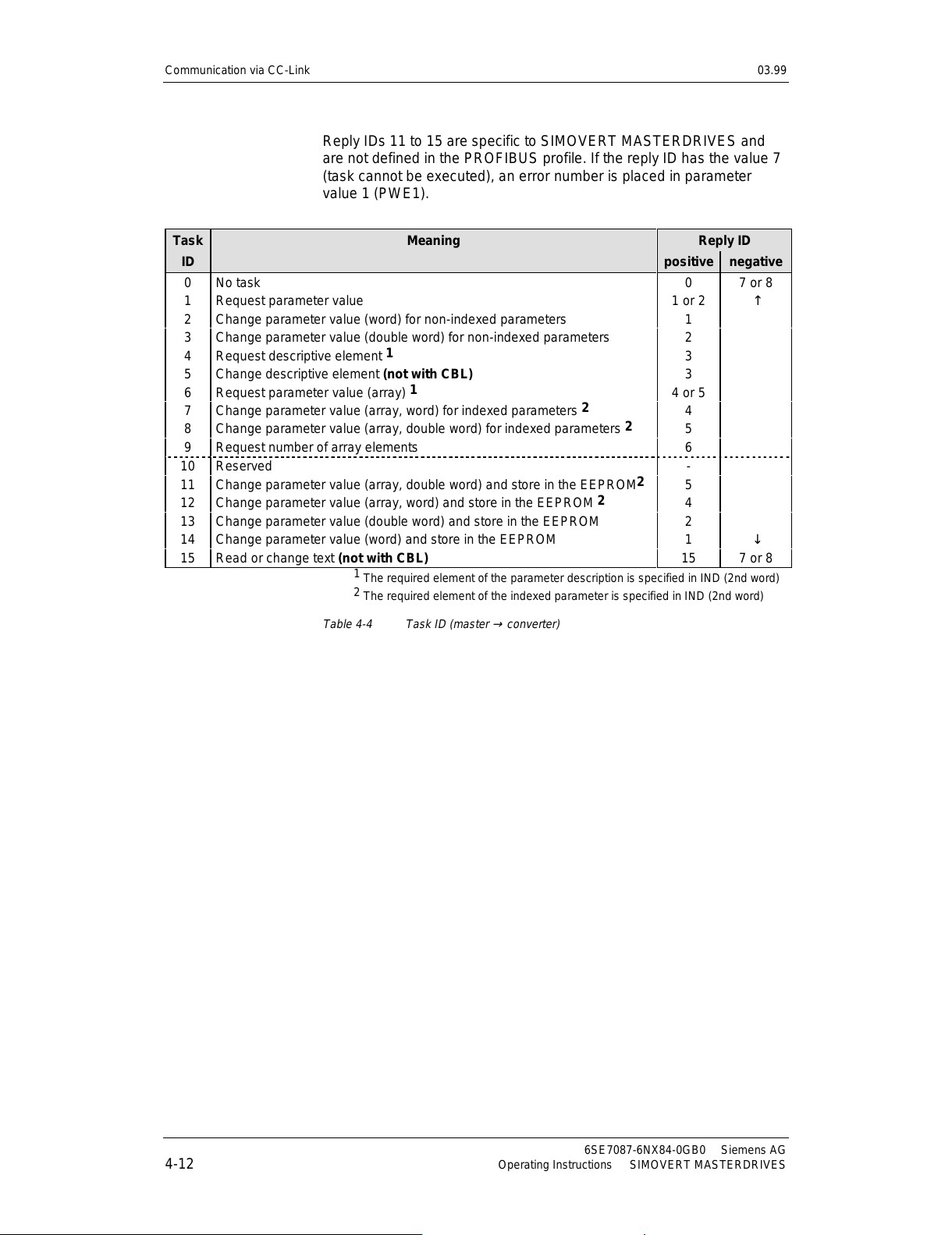
Reply IDs 11 to 15 are specific to SIMOVERT MASTERDRIVES and
are not defined in the PROFIBUS profile. If the reply ID has the value 7
(task cannot be executed), an error number is placed in parameter
value 1 (PWE1).
Task Meaning Reply ID
ID
positive negative
0 No task 0 7 or 8
1 Request parameter value 1 or 2 ↑
2 Change parameter value (word) for non-indexed parameters 1
3 Change parameter value (double word) for non-indexed parameters 2
4 Request descriptive element
1
3
5 Change descriptive element (not with CBL) 3
6 Request parameter value (array)
1
4 or 5
7 Change parameter value (array, word) for indexed parameters
2
4
8 Change parameter value (array, double word) for indexed parameters
2
5
9 Request number of array elements 6
10 Reserved -
11 Change parameter value (array, double word) and store in the EEPROM
2
5
12 Change parameter value (array, word) and store in the EEPROM
2
4
13 Change parameter value (double word) and store in the EEPROM 2
14 Change parameter value (word) and store in the EEPROM 1 ↓
15 Read or change text (not with CBL) 15 7 or 8
1
The required element of the parameter description is specified in IND (2nd word)
2
The required element of the indexed parameter is specified in IND (2nd word)
Table 4-4 Task ID (master → converter)
All manuals and user guides at all-guides.com
Page 33
03.99 Communication via CC-Link
Siemens AG 6SE7087-6NX84-0GB0
SIMOVERT MASTERDRIVES Operating Instructions 4-13
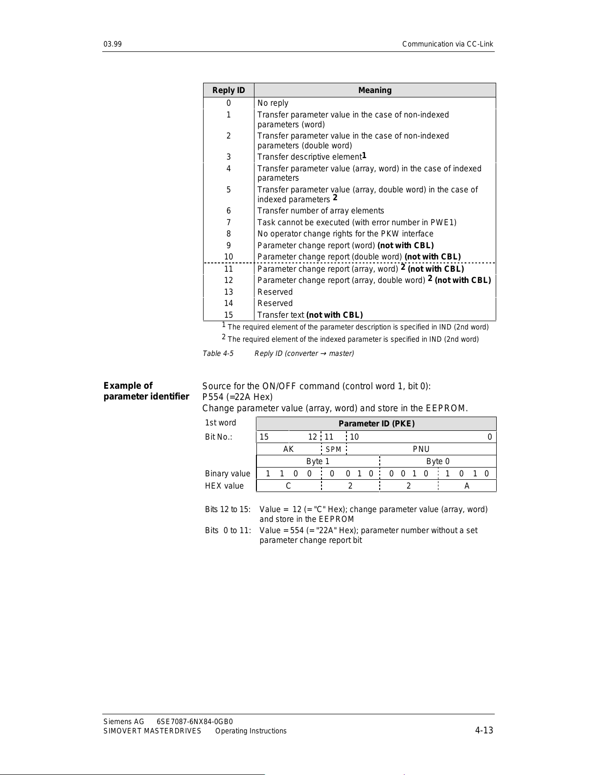
Reply ID Meaning
0 No reply
1 Transfer parameter value in the case of non-indexed
parameters (word)
2 Transfer parameter value in the case of non-indexed
parameters (double word)
3 Transfer descriptive element
1
4 Transfer parameter value (array, word) in the case of indexed
parameters
5
Transfer parameter value (array, double word) in the case of
indexed parameters
2
6 Transfer number of array elements
7 Task cannot be executed (with error number in PWE1)
8 No operator change rights for the PKW interface
9 Parameter change report (word) (not with CBL)
10 Parameter change report (double word) (not with CBL)
11 Parameter change report (array, word)
2
(not with CBL)
12 Parameter change report (array, double word)
2
(not with CBL)
13 Reserved
14 Reserved
15 Transfer text (not with CBL)
1
The required element of the parameter description is specified in IND (2nd word)
2
The required element of the indexed parameter is specified in IND (2nd word)
Table 4-5 Reply ID (converter → master)
Source for the ON/OFF command (control word 1, bit 0):
P554 (=22A Hex)
Change parameter value (array, word) and store in the EEPROM.
1st word
Parameter ID (PKE)
Bit No.: 15 12 11 10 0
AK SPM PNU
Byte 1 Byte 0
Binary value 1 1 0 0 0 0 1 0 0 0 1 0 1 0 1 0
HEX value C 2 2 A
Bits 12 to 15:
Bits 0 to 11:
Value = 12 (= "C" Hex); change parameter value (array, word)
and store in the EEPROM
Value = 554 (= "22A" Hex); parameter number without a set
parameter change report bit
Example of
parameter identifier
All manuals and user guides at all-guides.com
Page 34
Communication via CC-Link 03.99
6SE7087-6NX84-0GB0 Siemens AG
4-14 Operating Instructions SIMOVERT MASTERDRIVES
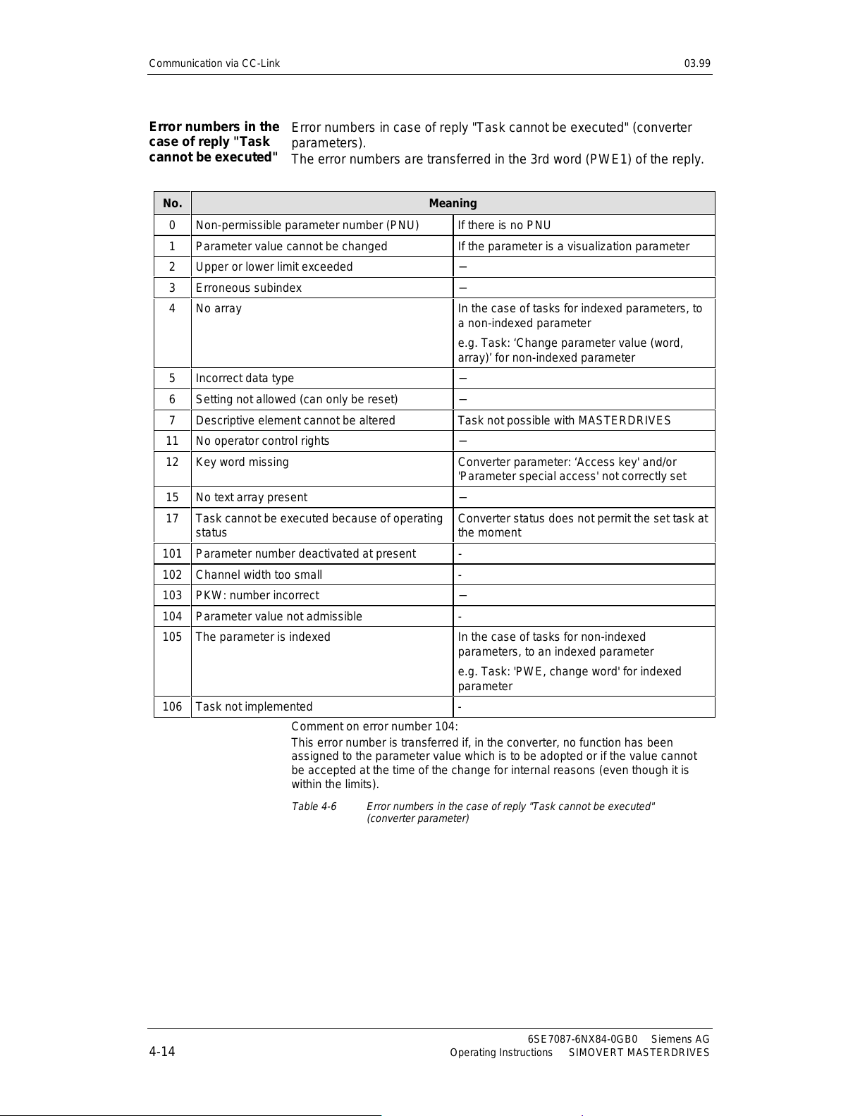
Error numbers in case of reply "Task cannot be executed" (converter
parameters).
The error numbers are transferred in the 3rd word (PWE1) of the reply.
No. Meaning
0 Non-permissible parameter number (PNU) If there is no PNU
1 Parameter value cannot be changed If the parameter is a visualization parameter
2 Upper or lower limit exceeded −
3 Erroneous subindex −
4 No array In the case of tasks for indexed parameters, to
a non-indexed parameter
e.g. Task: ‘Change parameter value (word,
array)’ for non-indexed parameter
5 Incorrect data type −
6 Setting not allowed (can only be reset) −
7 Descriptive element cannot be altered Task not possible with MASTERDRIVES
11 No operator control rights −
12 Key word missing
Converter parameter: ‘Access key' and/or
'Parameter special access' not correct ly set
15 No text array present −
17
Task cannot be executed because of operating
status
Converter status does not permit the set task at
the moment
101 Parameter number deactivated at present -
102 Channel width too small -
103 PKW: number incorrect −
104 Parameter value not admissible -
105 The parameter is indexed
In the case of tasks for non-indexed
parameters, to an indexed parameter
e.g. Task: 'PWE, change word' for indexed
parameter
106 Task not implemented -
Comment on error number 104:
This error number is transferred if, in the converter, no function has been
assigned to the parameter value which is to be adopted or if the value cannot
be accepted at the time of the change for internal reasons (even though it is
within the limits).
Table 4-6 Error numbers in the case of reply "Task cannot be executed"
(converter parameter)
Error numbers in the
case of reply "Task
cannot be executed"
All manuals and user guides at all-guides.com
Page 35
03.99 Communication via CC-Link
Siemens AG 6SE7087-6NX84-0GB0
SIMOVERT MASTERDRIVES Operating Instructions 4-15
The parameter ‘PKW number’ for the G-SST1 (number of net data in
the PKW channel):
Minimum v alue: 0 (0 words)
Maximum value: 127 (corresponds to variable length)
Permissible values for USS: 0, 3, 4 and 127
If a change task with a PWE other than 0, 3, 4 or 127 is sent to the
converter, the reply is: 'Task cannot be executed' with error value 104.
The index is an 8-bit value and is placed in bits 0 to 7. The bits 8 to 15
have additional features. Refer to instruction manual of the converter.
In the case of an indexed parameter, the required index is transferred.
The meaning of the indices can be found in the section, "Parameter
list", of the instruction manual for the converter.
In the case of a descriptive element, the number of the required
element is transferred. The meaning of the descriptive elements can be
found in the "PROFIBUS profile for variable-speed drives" (VDI/VDE
3689).
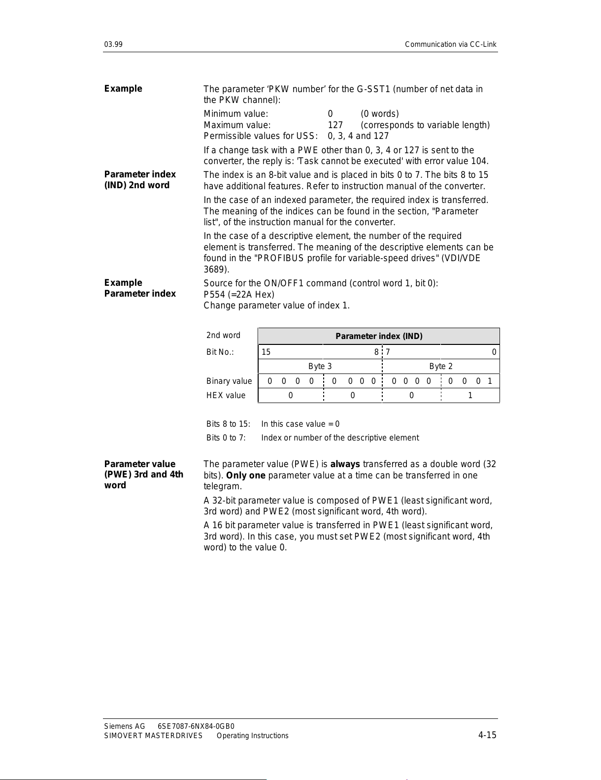
Source for the ON/OFF1 command (control word 1, bit 0):
P554 (=22A Hex)
Change parameter value of index 1.
2nd word
Parameter index (IND)
Bit No.: 15 8 7 0
Byte 3 Byte 2
Binary value 0 0 0 0 0 0 0 0 0 0 0 0 0 0 0 1
HEX value0 001
Bits 8 to 15:
Bits 0 to 7:
In this case value = 0
Index or number of the descriptive element
The parameter value (PWE) is always transferred as a double word (32
bits). Only one parameter value at a time can be transferred in one
telegram.
A 32-bit parameter value is composed of PWE1 (least significant word,
3rd word) and PWE2 (most significant wor d, 4th wor d).
A 16 bit parameter value is transferred in PWE1 (least significant word,
3rd word). In this case, you must set PWE2 (most significant word, 4th
word) to the value 0.
Example
Parameter index
(IND) 2nd word
Example
Parameter index
Parameter value
(PWE) 3rd and 4th
word
All manuals and user guides at all-guides.com
Page 36
Communication via CC-Link 03.99
6SE7087-6NX84-0GB0 Siemens AG
4-16 Operating Instructions SIMOVERT MASTERDRIVES
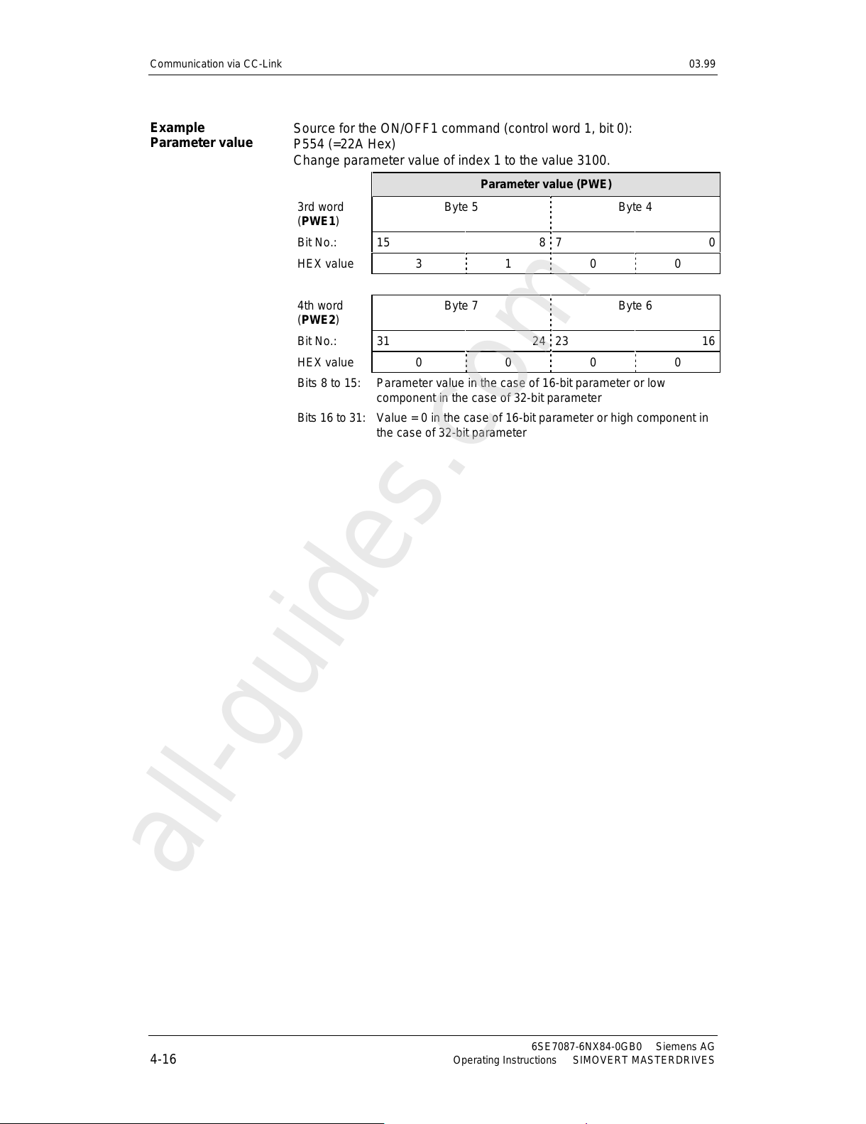
Source for the ON/OFF1 command (control word 1, bit 0):
P554 (=22A Hex)
Change parameter value of index 1 to the value 3100.
Parameter value (PWE)
3rd word
(PWE1)
Byte 5 Byte 4
Bit No.: 15 8 7 0
HEX value3 100
4th word
(PWE2)
Byte 7 Byte 6
Bit No.: 31 24 23 16
HEX value0 000
Bits 8 to 15:
Bits 16 to 31:
Parameter value in the case of 16-bit parameter or low
component in the case of 32-bit parameter
Value = 0 in the case of 16-bit parameter or high component in
the case of 32-bit parameter
Example
Parameter value
All manuals and user guides at all-guides.com
all-guides.com
Page 37
03.99 Communication via CC-Link
Siemens AG 6SE7087-6NX84-0GB0
SIMOVERT MASTERDRIVES Operating Instructions 4-17
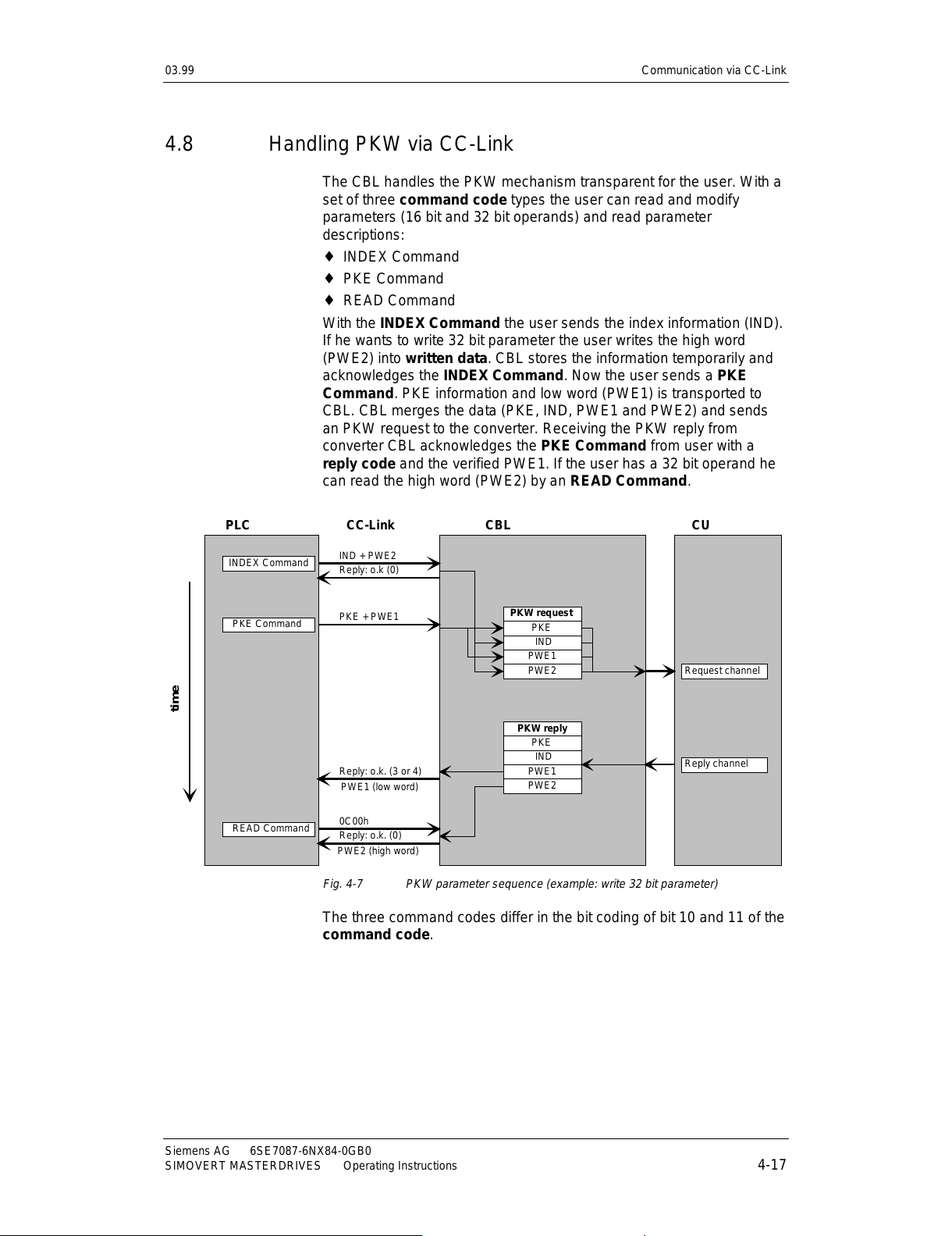
4.8 Handling PKW via CC-Link
The CBL handles the PKW mechanism transparent for the user. With a
set of three command code types the user can read and modify
parameters (16 bit and 32 bit operands) and read parameter
descriptions:
♦
INDEX Command
♦
PKE Command
♦
READ Command
With the INDEX Command
the user sends the index information (IND).
If he wants to write 32 bit parameter the user writes the high word
(PWE2) into written data
.
CBL stores the information temporarily and
acknowledges the INDEX Command
.
Now the user sends a PKE
Command
.
PKE information and low word (PWE1) is transported to
CBL. CBL merges the data (PKE, IND, PWE1 and PWE2) and sends
an PKW request to the converter. Receiving the PKW reply from
converter CBL acknowledges the PKE Command
from user with a
reply code and the verified PWE1. If the user has a 32 bit operand he
can read the high word (PWE2) by an READ Command
.
PKW request
PKE
IND
PWE1
PWE2
PKW reply
PKE
IND
PWE1
PWE2
IND + PWE2
0C00h
time
Reply: o.k (0)
PKE + PWE1
Reply: o.k. (3 or 4)
Reply: o.k. (0)
INDEX Command
READ Command
PKE Command
PLC CBL CUCC-Link
Request channel
Reply channel
PWE1 (low word)
PWE2 (high word)
Fig. 4-7 PKW parameter sequence (example: write 32 bit parameter)
The three command codes differ in the bit coding of bit 10 and 11 of the
command code.
All manuals and user guides at all-guides.com
Page 38
Communication via CC-Link 03.99
6SE7087-6NX84-0GB0 Siemens AG
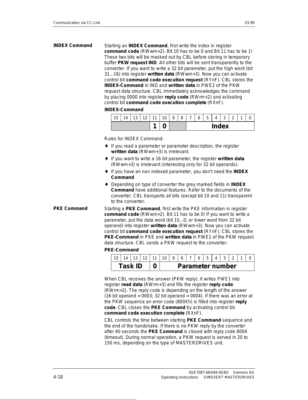
4-18 Operating Instructions SIMOVERT MASTERDRIVES
Starting an INDEX Command, first write the index in register
command code
(RWwm+2). Bit 10 has to be 0 and Bit 11 has to be 1!
These two bits will be masked out by CBL before storing in temporary
buffer PKW request IND
.
All other bits will be sent transparently to the
converter. If you want to write a 32 bit parameter, put the high word (bit
31...16) into register written data
(RWwm+3). Now you can activate
control bit command code execution request
(RYnF). CBL stores the
INDEX-Command
in IND and written data in PWE2 of the PKW
request data structure. CBL immediately acknowledges the command
by placing 0000 into register reply code
(RWrm+2) and activating
control bit command code execution complete
(RXnF).
INDEX-Command
1514131211109876543210
10 Index
Rules for INDEX Command:
♦
If you read a parameter or parameter description, the register
written data
(RWwm+3) is irrelevant.
♦
If you want to write a 16 bit parameter, the register written data
(RWwm+3) is irrelevant (interesting only for 32 bit operands).
♦
If you have an non indexed parameter, you don’t need the INDEX
Command
♦
Depending on type of converter the grey marked fields in INDEX
Command have additional features. Refer to the documents of the
converter. CBL transports all bits (except bit 10 and 11) transparent
to the converter.
Starting a PKE Command,
first write the PKE information in register
command code
(RWwm+2). Bit 11 has to be 0! If you want to write a
parameter, put the data word (bit 15...0; or lower word from 32 bit
operand) into register written data
(RWwm+3). Now you can activate
control bit command code execution request
(RYnF). CBL stores the
PKE-Command
in PKE and written data in PWE1 of the PKW request
data structure. CBL sends a PKW request to the converter.
PKE-Command
1514131211109876543210
Task ID 0 Parameter number
When CBL receives the answer (PKW reply), it writes PWE1 into
register read data
(RWrm+3) and fills the register reply code
(RWrm+2). The reply code is depending on the length of the answer
(16 bit operand = 0003; 32 bit operand = 0004). If there was an error at
the PKW sequence an error code (800Xh) is filled into register reply
code
.
CBL closes the PKE Command by activating control bit
command code execution complete
(RXnF).
CBL controls the time between starting PKE Command sequence and
the end of the handshake. If there is no PKW reply by the converter
after 40 seconds the PKE Command
is closed with reply code 8004
(timeout). During normal operation, a PKW request is served in 20 to
150 ms, depending on the type of MASTERDRIVES unit.
INDEX Command
PKE Command
All manuals and user guides at all-guides.com
Page 39
03.99 Communication via CC-Link
Siemens AG 6SE7087-6NX84-0GB0
SIMOVERT MASTERDRIVES Operating Instructions 4-19
After PKE Command
is executed CBL clears the register IND in the
PKW request structure; reason: fault tolerant handling; if you forget to
handle the INDEX Command
before PKE Command by accessing
indexed parameters an error message will be generated from the
converter.
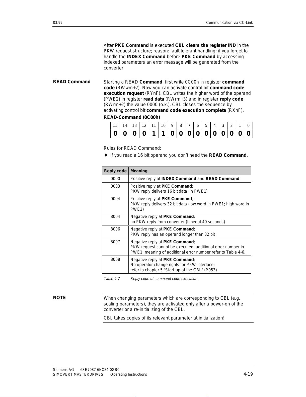
Starting a READ
Command, first write 0C00h in register command
code
(RWwm+2). Now you can activate control bit command code
execution request
(RYnF). CBL writes the higher word of the operand
(PWE2) in register read data
(RWrm+3) and in register reply code
(RWrm+2) the value 0000 (o.k.). CBL closes the sequence by
activating control bit command code execution complete
(RXnF).
READ-Command (0C00h)
1514131211109876543210
0000 1 10000000000
Rules for READ Command:
♦
If you read a 16 bit operand you don’t need the READ Command
.
Reply code Meaning
0000 Positive reply at INDEX Command and READ Command
0003
Positive reply at PKE Command;
PKW reply delivers 16 bit data (in PWE1)
0004
Positive reply at PKE Command
;
PKW reply delivers 32 bit data (low word in PWE1; high word in
PWE2)
8004 Negative reply at PKE Command;
no PKW reply from converter (timeout 40 seconds)
8006 Negative reply at PKE Command;
PKW reply has an operand longer than 32 bit
8007 Negative reply at PKE Command;
PKW request cannot be executed; additional error number in
PWE1; meaning of additional error number refer to Table 4-6.
8008
Negative reply at PKE Command;
No operator change rights for PKW interface;
refer to chapter 5 "Start-up of the CBL" (P053)
Table 4-7 Reply code of command code execution
When changing parameters which are corresponding to CBL (e.g.
scaling parameters), they are activated only after a power-on of the
converter or a re-initializing of the CBL.
CBL takes copies of its relevant parameter at initialization!
READ Command
NOTE
All manuals and user guides at all-guides.com
Page 40
Communication via CC-Link 03.99
6SE7087-6NX84-0GB0 Siemens AG
4-20 Operating Instructions SIMOVERT MASTERDRIVES
You want to change the setpoint input (source main setpoint) to fixed
setpoints because you want to control the drive by the bits RL, RM and
RH:
1) Read the actual value of parameter P443 (only information):
Because parameter P443 is an indexed parameter you send first time
an INDEX Command:
Command Code (RWwm+2) = 0801h
Written Data (RWwm+3) = irrelevant
You want to read index 1. There is no write sequence, so register
Written data is irrelevant. You start the command
code execution by
activating RYnF (=1).
CBL react with activating RXnF (complete flag). You see:
Reply Code (RWrm+2) = 0000h
Read Data (RWrm+3) = irrelevant
Reply code 0000 means no error. Deactivate RYnF! CBL also
deactivates RXnF.
Now you send a PKE Command:
Command Code (RWwm+2) = 61BBh
Written Data (RWwm+3) = irrelevant
You want to read to an indexed (array) word (16-bit): Task ID is 6 (PKE
bit 15...12). Parameter 443 (decimal) is 1BBh (hexadecimal).
After you have activated the command
code execution you get the
acknowledge command complete from CBL. You see:
Reply Code (RWrm+2) = 0003h
Read Data (RWrm+3) = 3002h
Reply code 0003 indicates there was no error and the answer is a 16
bit word (reply code 0004 means 32 bit word). P443 = 3002 shows you,
that the source main setpoint is routed to CBL interface (first
communication board interface: PZD2 = setpoint).
A READ Command is not relevant because you have only a 16-bit
word in the PKW reply.
2) Write parameter P443 = 0040:
Because parameter P443 is an indexed parameter you send first time
an INDEX Command:
Command Code (RWwm+2) = 0801h
Written Data (RWwm+3) = irrelevant
Register Written data is irrelevant because P443 is a 16-bit parameter.
You activate INDEX Command
and get the reply:
Reply Code (RWrm+2) = 0000h
Read Data (RWrm+3) = irrelevant
Now you send a PKE Command:
Command Code (RWwm+2) = 71BBh
Written Data (RWwm+3) = 0040
Example
All manuals and user guides at all-guides.com
Page 41
03.99 Communication via CC-Link
Siemens AG 6SE7087-6NX84-0GB0
SIMOVERT MASTERDRIVES Operating Instructions 4-21
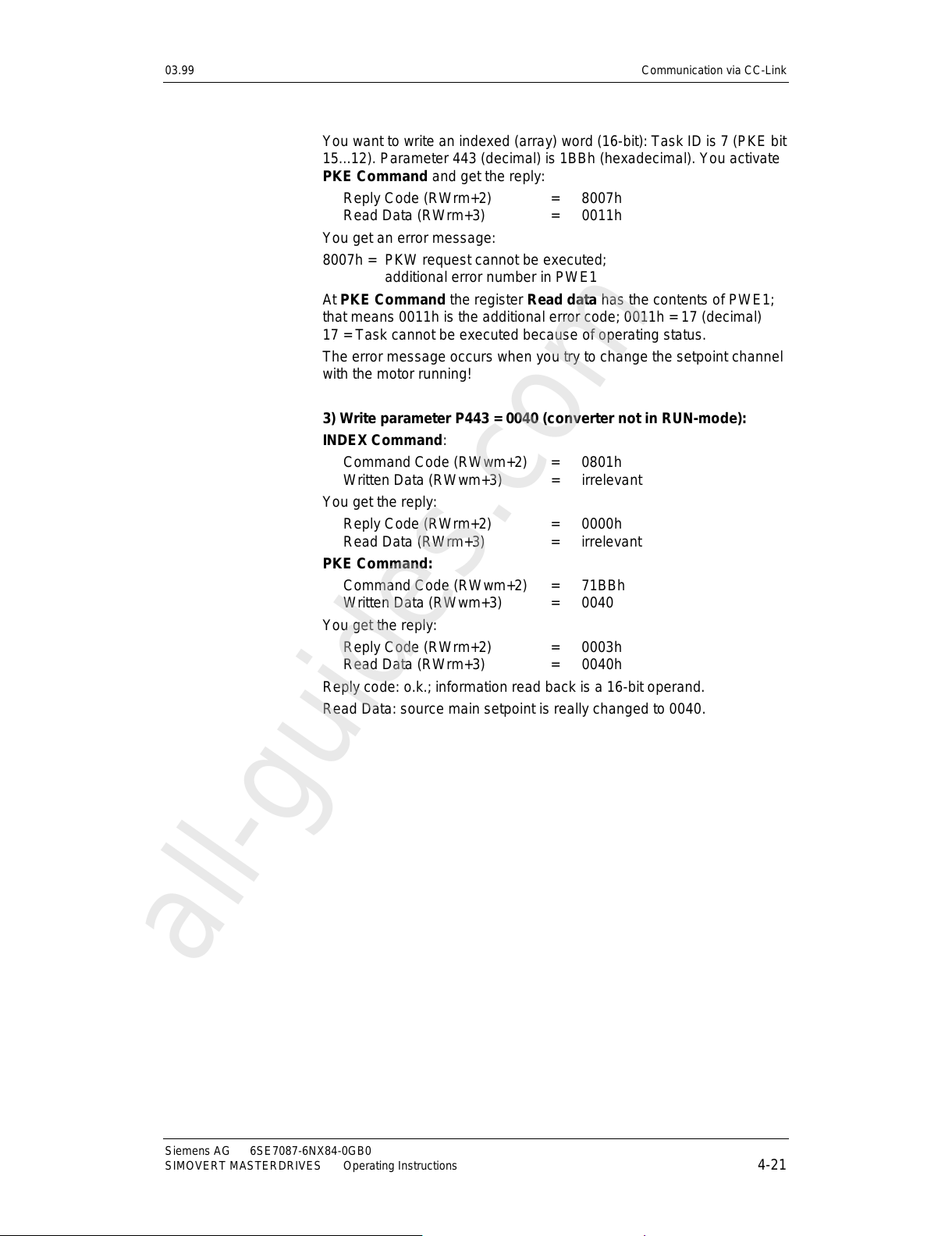
You want to write an indexed (array) word (16-bit): Task ID is 7 (PKE bit
15...12). Parameter 443 (decimal) is 1BBh (hexadecimal). You activate
PKE Command and get the reply:
Reply Code (RWrm+2) = 8007h
Read Data (RWrm+3) = 0011h
You get an error message:
8007h = PKW request cannot be executed;
additional error number in PWE1
At PKE Command the register Read data has the contents of PWE1;
that means 0011h is the additional error code; 0011h = 17 (decimal)
17 = Task cannot be executed because of operating status.
The error message occurs when you try to change the setpoint channel
with the motor running!
3) Write parameter P443 = 0040 (converter not in RUN-mode):
INDEX Command:
Command Code (RWwm+2) = 0801h
Written Data (RWwm+3) = irrelevant
You get the reply:
Reply Code (RWrm+2) = 0000h
Read Data (RWrm+3) = irrelevant
PKE Command:
Command Code (RWwm+2) = 71BBh
Written Data (RWwm+3) = 0040
You get the reply:
Reply Code (RWrm+2) = 0003h
Read Data (RWrm+3) = 0040h
Reply code: o.k.; information read back is a 16-bit operand.
Read Data: source main setpoint is really changed to 0040.
All manuals and user guides at all-guides.com
all-guides.com
Page 42

Communication via CC-Link 03.99
6SE7087-6NX84-0GB0 Siemens AG
4-22 Operating Instructions SIMOVERT MASTERDRIVES
4.9 Data formats and data conversion
Mitsubishi converters handle data as unsigned 16 bit integer. The
direction of rotation is coded in control bits STF (RYn0) and STR
(RYn1). Depending on the process value (e.g. current, frequency) this
integer value gets a precision fa ctor :
Process
value
Precision integer
(1 digit)
Frequency 0.01 Hz
Current 0.01 A
Voltage 0.1 V
Torque 0.1 %
Rotation 1 Rotation/minute
Table 4-8 Mitsubishi data format; precision
SIMOVERT MASTERDRIVES works internally with process values in
16 bit or 32 bit signed integer (2nd-complement). These values are
normalized in percent:
Integer value
16 bit 32 bit Real value
.
.
4000h
.
.
0000h
.
.
C000h
.
.
.
.
4000.0000h
.
.
0000.0000h
.
.
C000.0000h
.
.
.
.
+ 100 %
.
.
0 %
.
.
– 100 %
.
.
Table 4-9 SIMOVERT MASTERDRIVES int ernal data format
The display of SIMOVERT MASTERDRIVES shows the absolute value.
For this reason there are parameters with scaling factors (e.g.
P350...P353). Their contents are the absolute value at + 100 %.
CBL has to convert the data from Mitsubishi data format in
MASTERDRIVES data format and vice versa. The CBL uses
parameters (P715...P718) pointing to the scaling parameters
(P350...P353). Other scaling factors may be parameterized. Normally
the user sets P715 = 350, P716 = 351, etc. In this way CBL use the
same scaling factors like display routines of the converter. CBL
automatically adapts the precision between Mitsubishi data format and
MASTERDRIVES display format. It uses the parameter description
(conversion index in IEEE format) of the scaling factor parameters.
Data format
Mitsubishi
converter
Data format
SIMOVERT
MASTERDRIVES
All manuals and user guides at all-guides.com
Page 43

03.99 Communication via CC-Link
Siemens AG 6SE7087-6NX84-0GB0
SIMOVERT MASTERDRIVES Operating Instructions 4-23
You have two ways to handle the process values:
1) Working with the Mitsubishi data format:
All reference values (setpoints) and actual values are in the format
like Table 4-8. The 16-bit-variables are unsigned integer values.
CBL converts all values in both communication directions incl.
monitoring; refer to figures in this chapter.
In this case you have to set the parameter:
P715 = 350 (current)
P716 = 351 (voltage)
P717 = 352 (frequency)
P718 = 353 (rotation per minute)
2) Working with the internal MASTERDRIVES format:
All reference values (setpoints) and actual values are in the format
like Table 4-9. Exception: At PLC side all values are positive
(unsigned)! The sign (positive or negative) is controlled by the
direction bits STF (RYn0) and STR (RYn1). CBL doesn’t convert the
setpoints. Actual values and monitoring values are converted to
unsigned integer.
In this case you have to set the parameter:
P715 = 0 (current)
P716 = 0 (voltage)
P717 = 0 (frequency)
P718 = 0 (rotation per minute)
The CB parameters P715...P718 are pointers to scaling parameters.
If a CB parameter (P715...P718) is 0, the corresponding type of
process value isn’t converted by CBL.
Normally use for parameter P715...P718 the scaling factor parameters
P350...P353.
Mixing is possible; that means some values are converted by CBL other
ones are not modified.
P717 = 352; ⇒ P352 = 50.00;
actual value frequency = 2000h (MASTERDRIVES internal data format)
P352 shows, that 100 % of a frequency value is 50.00 Hz. The CB
parameter P717 points to the parameter P352 "scaling factor
frequency"; 100 % equals 4000h. CBL calculates an actual value:
2000h / 4000h * 5000 = 2500 = 9C4h
The following function diagrams show the data conversion of CBL in the
different data channels:
NOTE
Example
All manuals and user guides at all-guides.com
Page 44

Communication via CC-Link 03.99
6SE7087-6NX84-0GB0 Siemens AG
4-24 Operating Instructions SIMOVERT MASTERDRIVES
Frequency control:
Set frequency (RWwm+1)
unsigned
16-bit-intege r
Pxxx
P717
P717 # 0
P717 = 0
P717 = xxx
MASTERDRIVES format
unsigned!
0 ... 200 %
STR (RYn1)
Forward enable (ct rl. word bit11)
XOR
ON/OFF1 (ctrl.word bit 0)
STF (RYn0)
STF STR Bit11 Bit 12
0 0 1 1
1 0 1 0
0 1 0 1
1 1 1 1
Reverse enable (ct rl. word bit12)
7FFFh
Fig. 4-8 Data conversion at setpoint channel "frequency control"
If P717 equals 0, then setpoints are interpreted from CBL as
percentage values in MASTERDRIVES format (unsigned in this case!)
between 0 and 7FFFh (0 % ... 200 %); e.g. set frequency
= 1000h
⇒
25 %. Values greater than 7FFFh will be set to 7FFFh.
If P717 greater than 0 (P717 is a pointer to scaling parameter), the
unsigned integer value corresponds to the frequency value; e.g. set
frequency = 2000 ⇒ 20.00 Hz.
Torque control:
Set frequency
(RWwm+1)
unsigned
16-bit-integer
fixed scaling parameter "torque"
MASTERDRIVES format
signed 16 bit!
-200 %... +200 %
STR (RYn1)
Forward enable (ctrl.word bit11)
XOR
ON/OFF1 (ctrl.word bit 0)
STF (RYn0)
STF STR Bit11 Bit 12
0 0 1 1
1 0 1 0
0 1 0 1
1 1 1 1
Reverse enable (ctrl.word bit12)
-1
STF,STR
1,0
0,0
1,1
0,1
0
not
relevant
for
torque
control
7FFFh
Fig. 4-9 Data conversion at setpoint channel "torque control"
Data conversion of
setpoints at
frequency set
command
All manuals and user guides at all-guides.com
Page 45

03.99 Communication via CC-Link
Siemens AG 6SE7087-6NX84-0GB0
SIMOVERT MASTERDRIVES Operating Instructions 4-25
At torque control there is a fixed scaling parameter instead of P717. So
torque setpoints everytime converted from unsigned integer format of
Mitsubishi inverter into signed MASTERDRIVES value (0 %...200 %).
The direction of rotation is coded into the sign of the torque setpoint.
CBL creates the 2th-complement of the setpoint if STR = 1 and
STF = 0.
Actual frequency (RWrm+1)
unsigned 16-bit-integer
Pxxx
P717
P717 # 0
P717 = 0
P717 = xxx
Revers e operation (RXn1)
> 0
< 0
Forward operation (RXn0)
Actual value
(PZD2)
signed 16-bit-value
MASTERDRIVES format
-200 % ... +200 %
FFFFh
Fig. 4-10 Data conversion at actual value channel
At torque control there is a fixed scaling parameter instead of P717. So
torque actual values everytime converted from signed
MASTERDRIVES value (-200 %...+200 %) into unsigned integer format
of Mitsubishi inverter.
Monitoring value
(RWrm)
16-bit-integer
Pxxx
P71y
P71y # 0
P71y = 0
according scaling pointer
P71y = xxx
Actual monitoring value
(PZDn) 16- bit-value
Monitoring code
<8000h
>8000h
Fig. 4-11 Data conversion at monitoring channel
Data conversion of
actual value
Data conversion at
monitoring
All manuals and user guides at all-guides.com
Page 46

Communication via CC-Link 03.99
6SE7087-6NX84-0GB0 Siemens AG
4-26 Operating Instructions SIMOVERT MASTERDRIVES
4.10 Fault reaction on communication errors
If the communication via CC-Link breaks down (e.g. PLC cpu goes into
fault, CC-Link cable is disconnected) the reaction of the drive can be
programmed depending on your application.
This is selectable by communic ati on board par ameter P712 bit 0
"HOLD/CLR function".
P712 bit 0 = 1: CLR function
When communication breaks down CBL detects the fault. CBL reacts
by sending setpoint 0000 and neutral control bits to the converter. The
drive stops.
Remark: Set P722 (Telegram failure time) to 0000.
P712 bit 0 = 0: HOLD function
When communication breaks down CBL detects the fault. CBL don’t
react. It gives no further information (telegrams) to the converter. Actual
control bits and setpoint are further valid. Drive is still running. Now you
can handle the fault reaction by the fault mechanism of the converter.
With converter parameter P722 (Telegram failure time) you can
supervise the setpoint channel from the communication board. If there
is no new telegram from CBL at the setpoint channel in the time interval
parameterized in P722, the fault mechanism of the converter starts;
refer to documentation of converter.
HOLD / CLR-
function
All manuals and user guides at all-guides.com
all-guides.com
Page 47

03.99 Communication via CC-Link
Siemens AG 6SE7087-6NX84-0GB0
SIMOVERT MASTERDRIVES Operating Instructions 4-27
4.11 Optional flags in CBL profile
In the remote IO bit structure there are some additional flags named
♦
Optionflags 27, 28, 29 (F27 ... F29)
♦
Infoflags 0, 7, 15 (I0 ... I15)
The optionflags are freely routable additional bits to control special
functions in the converter. CBL transports these bits to the dual port
RAM interface. Here you can route the binectors of PZD4 (status word
2) bit 27 till 29 (bit 11...13 of the 16-bit word) to your special function of
your application.
Example:
If you want to use the function "OFF3: quick stop" from the PLC route
e.g. P558 = 3411. Parameter P558 is one of three inputs (and-function)
of control word bit OFF3; B3411 is the binector PZD4 bit 11 of the first
communication board; refer to function diagrams 120 and 180 of
converter documentation.
The infoflags give you additional information from the status word of the
converter:
CC-Link
Remote IO Bit
Converter
statusword
Meaning
RXn8 = I0 Bit 0 Ready to switch on
RXn9 = I7 Bit 7 Warning active
RxnA = I15 Bit 15 Reserved; refer to converter
documentation
Table 4-10 Additional infoflags
Optionflags
Infoflags
All manuals and user guides at all-guides.com
Page 48

All manuals and user guides at all-guides.com
Page 49
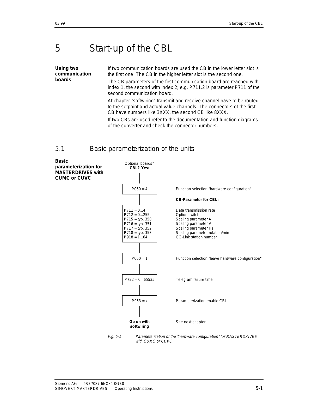
03.99 Start-up of the CBL
Siemens AG 6SE7087-6NX84-0GB0
SIMOVERT MASTERDRIVES Operating Instructions 5-1
5 Start-up of the CBL
If two communication boards are used the CB in the lower letter slot is
the first one. The CB in the higher letter slot is the second one.
The CB parameters of the first communication board are reached with
index 1, the second with index 2; e.g. P711.2 is parameter P711 of the
second communication board.
At chapter "softwiring" transmit and receive channel have to be routed
to the setpoint and actual value channels. The connectors of the first
CB have numbers like 3XXX, the second CB like 8XXX.
If two CBs are used refer to the documentation and function diagrams
of the converter and check the connector numbers.
5.1 Basic parameterization of the units
Optional boards?
CBL? Yes:
P060 = 4 Function selection "hardware configurati on"
CB-Parameter for CBL:
P711 = 0...4
P712 = 0...255
P715 = typ. 350
P716 = typ. 351
P717 = typ. 352
P718 = typ. 353
P918 = 1...64
Data transmission rate
Option switch
Scaling parameter A
Scaling parameter V
Scaling parameter Hz
Scaling parameter rotation/min
CC-Link station number
P060 = 1 Function selection "leave hardware configuration"
P722 = 0...65535 Telegram failure time
P053 = x Parameterizati on enabl e CBL
Go on with
softwiring
See next chapter
Fig. 5-1 Parameterization of the "hardware configurat i on" for MASTERDRIVES
with CUMC or CUVC
Using two
communication
boards
Basic
parameterization for
MASTERDRIVES with
CUMC or CUVC
All manuals and user guides at all-guides.com
Page 50
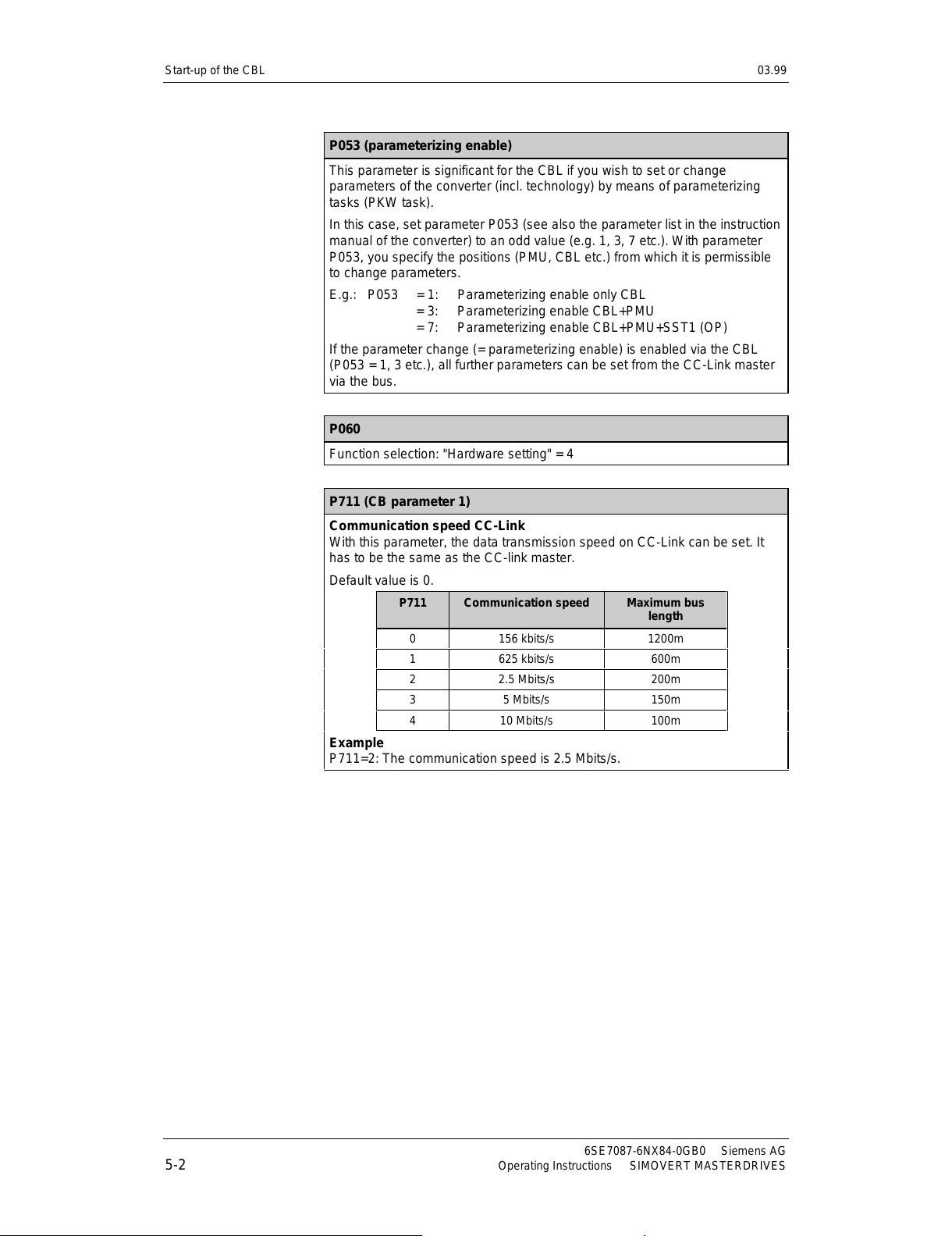
Start-up of the CBL 03.99
6SE7087-6NX84-0GB0 Siemens AG
5-2 Operating Instructions SIMOVERT MASTERDRIVES
P053 (parameterizing enable)
This parameter is significant for the CBL if you wish to set or change
parameters of the converter (incl. technology) by means of parameterizing
tasks (PKW task).
In this case, set parameter P053 (see also the parameter list in the instruction
manual of the converter) to an odd value (e.g. 1, 3, 7 etc.). With parameter
P053, you specify the positions (PMU, CBL etc.) from which it is permissible
to change parameters.
E.g.: P053 = 1: Parameterizing enable only CBL
= 3: Parameterizing enable CBL+PMU
= 7: Param eterizing enable CBL+PMU+SST1 (OP)
If the parameter change (= parameterizing enable) is enabled via the CBL
(P053 = 1, 3 etc.), all further parameters can be set from the CC-Link master
via the bus.
P060
Function selection: "Hardware setting" = 4
P711 (CB parameter 1)
Communication speed CC-Link
With this parameter, the data transmission speed on CC-Link can be set. It
has to be the same as the CC-link master.
Default value is 0.
P711 Comm unicati o n speed Maximum bus
length
0 156 kbits/s 1200m
1 625 kbits/s 600m
2 2.5 Mbits/s 200m
3 5 Mbits/s 150m
4 10 Mbits/s 100m
Example
P711=2: The communication speed is 2.5 Mbits/s.
All manuals and user guides at all-guides.com
Page 51
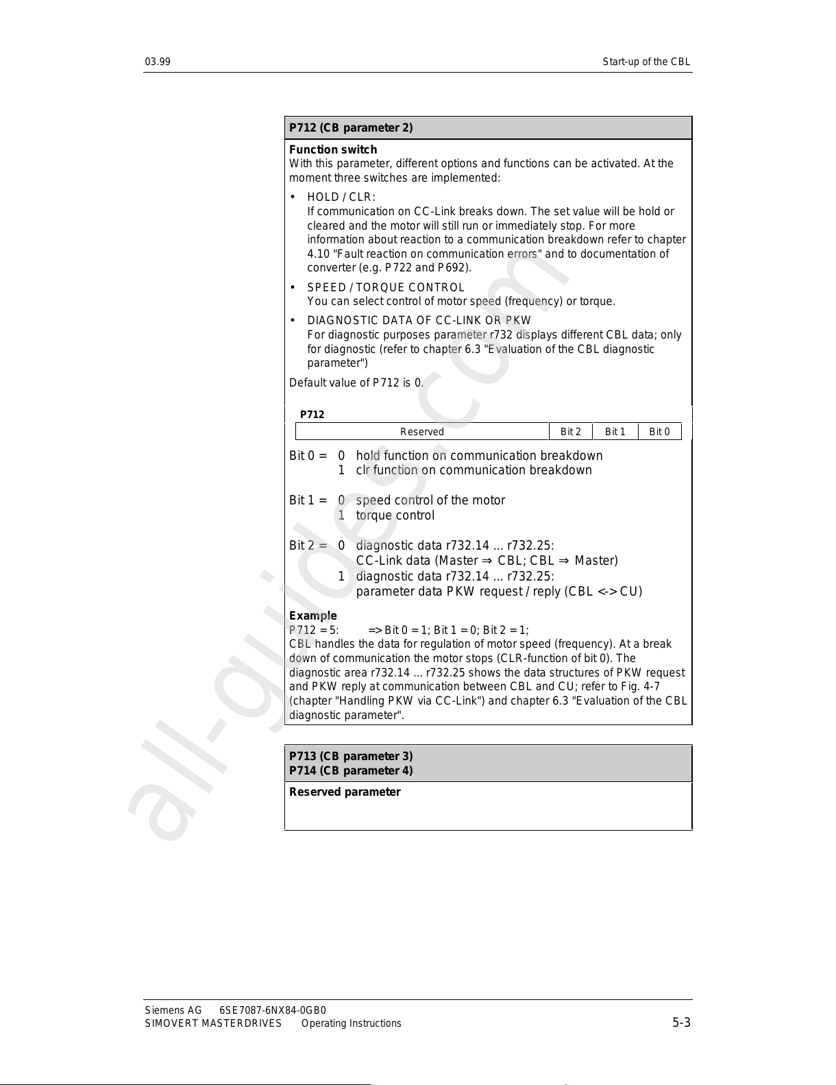
03.99 Start-up of the CBL
Siemens AG 6SE7087-6NX84-0GB0
SIMOVERT MASTERDRIVES Operating Instructions 5-3
P712 (CB parameter 2)
Function switch
With this parameter, different options and functions can be activated. At the
moment three switches are implemented:
• HOLD / CLR:
If communication on CC-Link breaks down. The set value will be hold or
cleared and the motor will still run or immediately stop. For more
information about reaction to a communication breakdown refer to chapter
4.10 "Fault reaction on communication errors" and to docu men tation of
converter (e.g. P722 and P692).
• SPEED / TORQUE CONTROL
You can select control of motor speed (frequency) or torque.
• DIAGNOSTIC DATA OF CC-LINK OR PKW
For diagnostic purposes parameter r732 displays different CBL data; only
for diagnostic (refer to chapter 6.3 "Evaluation of the CBL diagnostic
parameter")
Default value of P712 is 0.
P712
Reserved Bit 2 Bit 1 Bit 0
Bit 0 = 0 hold function on communication breakdown
1 clr function on communication breakdown
Bit 1 = 0 speed control of the motor
1 torque control
Bit 2 = 0 diagnostic data r732.14 ... r732.25:
CC-Link data (Master ⇒ CBL; CBL ⇒ Master)
1 diagnostic data r732.14 ... r732.25:
parameter data PKW request / reply (CBL <-> CU)
Example
P712 = 5: => Bit 0 = 1; Bit 1 = 0; Bit 2 = 1;
CBL handles the data for regulation of motor speed (frequency). At a break
down of communication the motor stops (CLR-function of bit 0). The
diagnostic area r732.14 ... r732.25 shows the data structures of PKW request
and PKW reply at communication between CBL and CU; refer to Fig. 4-7
(chapter "Handling PKW via CC-Link") and chapter 6.3 "Evaluation of the CBL
diagnostic parameter".
P713 (CB parameter 3)
P714 (CB parameter 4)
Reserved parameter
All manuals and user guides at all-guides.com
all-guides.com
Page 52
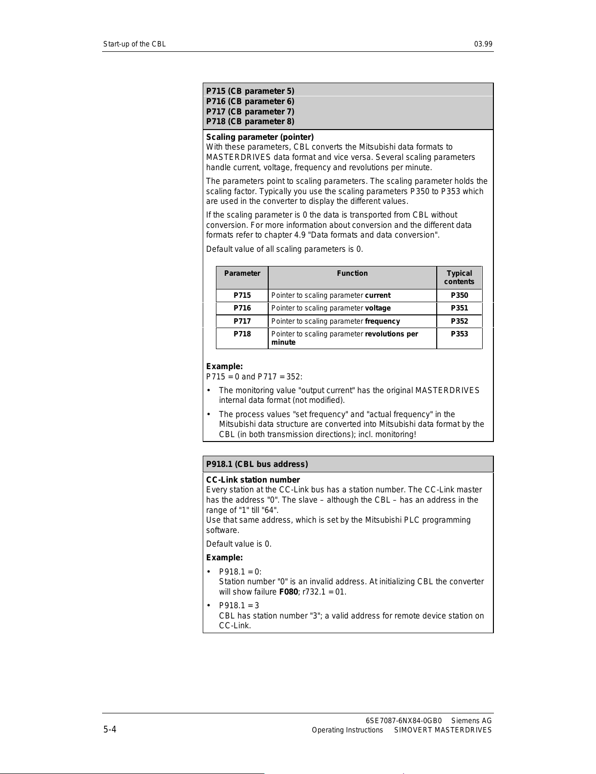
Start-up of the CBL 03.99
6SE7087-6NX84-0GB0 Siemens AG
5-4 Operating Instructions SIMOVERT MASTERDRIVES
P715 (CB parameter 5)
P716 (CB parameter 6)
P717 (CB parameter 7)
P718 (CB parameter 8)
Scaling parameter (pointer)
With these parameters, CBL converts the Mitsubishi data formats to
MASTERDRIVES data format and vice versa. Several scaling parameters
handle current, voltage, frequency and revolutions per minute.
The parameters point to scaling parameters. The scaling parameter holds the
scaling factor. Typically you use the scaling parameters P350 to P353 which
are used in the converter to display the different values.
If the scaling parameter is 0 the data is transported from CBL without
conversion. For more information about conversion and the different data
formats refer to chapter 4.9 "Data formats and data conversion".
Default value of all scaling parameters is 0.
Parameter Function Typical
contents
P715 Pointer to scaling parameter current P350
P716 Pointer to scaling parameter voltage P351
P717 Pointer to scaling parameter frequency P352
P718 Pointer to scaling parameter revolutions per
minute
P353
Example:
P715 = 0 and P717 = 352:
• The monitoring value "output current" has the original MASTERDRIVES
internal data format (not modified).
• The process values "set frequency" and "actual frequency" in the
Mitsubishi data structure are converted into Mitsubishi data format by the
CBL (in both transmission directions); incl. monitoring!
P918.1 (CBL bus address)
CC-Link station number
Every station at the CC-Link bus has a station number. The CC-Link master
has the address "0". The slave – although the CBL – has an address in the
range of "1" till "64".
Use that same address, which is set by the Mitsubishi PLC programming
software.
Default value is 0.
Example:
• P918.1 = 0:
Station number "0" is an invalid address. At initializing CBL the converter
will show failure F080; r732.1 = 01.
• P918.1 = 3
CBL has station number "3"; a valid address for remote device station on
CC-Link.
All manuals and user guides at all-guides.com
Page 53
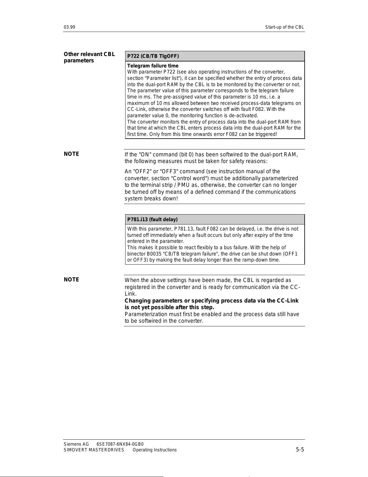
03.99 Start-up of the CBL
Siemens AG 6SE7087-6NX84-0GB0
SIMOVERT MASTERDRIVES Operating Instructions 5-5
P722 (CB/TB TlgOFF)
Telegram failure time
With parameter P722 (see also operating instructions of the converter,
section "Parameter list"), it can be specified whether the entry of process data
into the dual-port RAM by the CBL is to be monitored by the converter or not.
The parameter value of this parameter corresponds to the telegram failure
time in ms. The pre-assigned value of this parameter is 10 ms, i.e. a
maximum of 10 ms allowed between two received process-data telegrams on
CC-Link, otherwise the converter switches off with fault F082. With the
parameter value 0, the monitoring function is de-activated.
The converter monitors the entry of process data into the dual-port RAM from
that time at which the CBL enters process data into the dual-port RAM for the
first time. Only from this time onwards error F082 can be triggered!
If the "ON" command (bit 0) has been softwired to the dual-port RAM,
the following measures must be taken for safety reasons:
An "OFF2" or "OFF3" command (see instruction manual of the
converter, section "Control word") must be additionally parameterized
to the terminal strip / PMU as, otherwise, the converter can no longer
be turned off by means of a defined command if the communications
system breaks down!
P781.i13 (fault delay)
With this parameter, P781.13, fault F082 can be delayed, i.e. the drive is not
turned off immediately when a fault occurs but only after expiry of the time
entered in the parameter.
This makes it possible to react flexibly to a bus failure. With the help of
binector B0035 "CB/TB telegram failure", the drive can be shut down (OFF1
or OFF3) by making the fault delay longer than the ramp-down time.
When the above settings have been made, the CBL is regarded as
registered in the converter and is ready for communication via the CC-
Link.
Changing parameters or specifying process data via the CC-Link
is not yet possible after this step.
Parameterization must first be enabled and the process data still have
to be softwired in the converter.
Other relevant CBL
parameters
NOTE
NOTE
All manuals and user guides at all-guides.com
Page 54
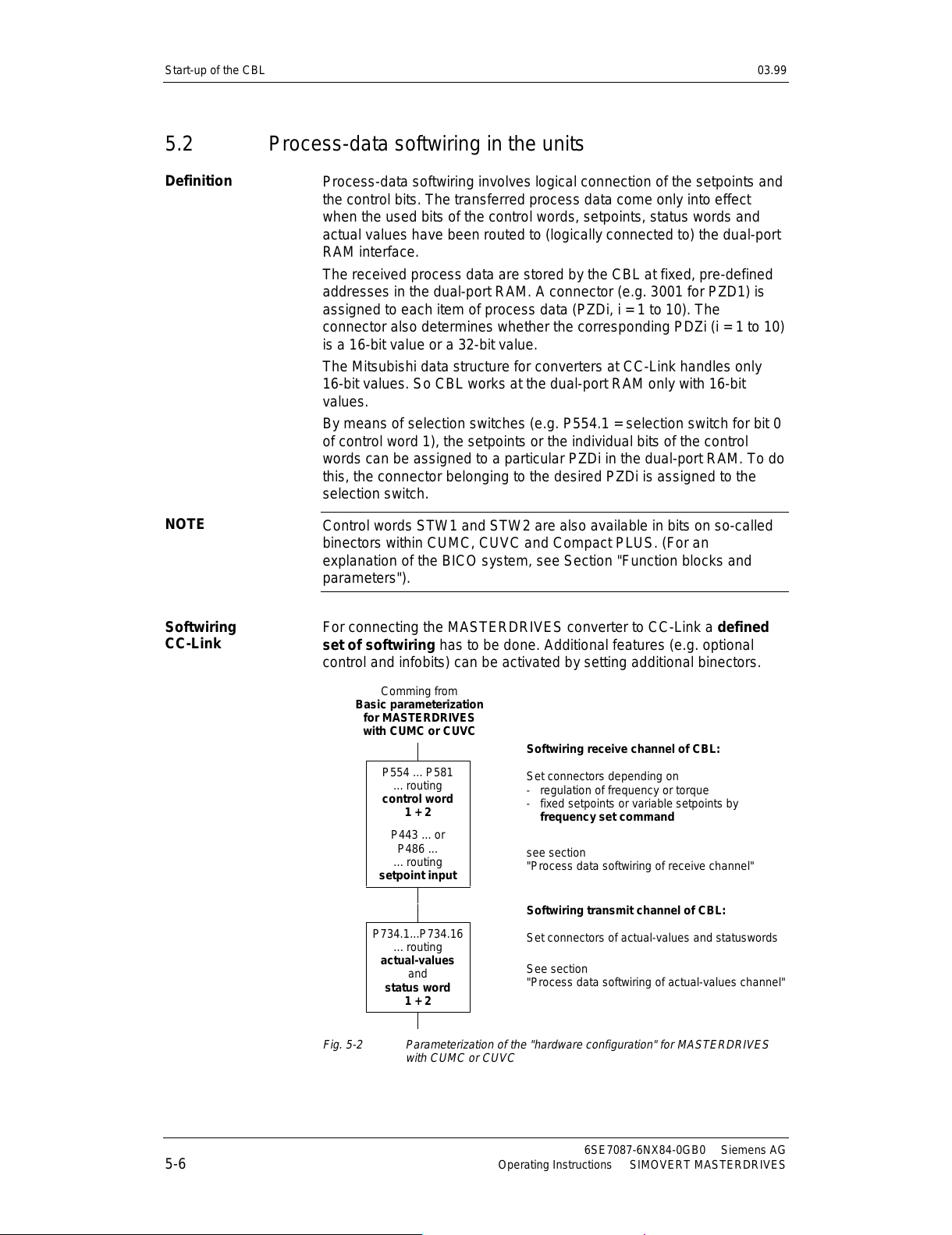
Start-up of the CBL 03.99
6SE7087-6NX84-0GB0 Siemens AG
5-6 Operating Instructions SIMOVERT MASTERDRIVES
5.2 Process-data softwiring in the units
Process-data softwiring involves logical connection of the setpoints and
the control bits. The transferred process data come only into effect
when the used bits of the control words, setpoints, status words and
actual values have been routed to (logically connected to) the dual-port
RAM interface.
The received process data are stored by the CBL at fixed, pre-defined
addresses in the dual-port RAM. A connector (e.g. 3001 for PZD1) is
assigned to each item of process data (PZDi, i = 1 to 10). The
connector also determines whether the corresponding PDZi (i = 1 to 10)
is a 16-bit value or a 32-bit value.
The Mitsubishi data structure for converters at CC-Link handles only
16-bit values. So CBL works at the dual-port RAM only with 16-bit
values.
By means of selection switches (e.g. P554.1 = selection switch for bit 0
of control word 1), the setpoints or the individual bits of the control
words can be assigned to a particular PZDi in the dual-port RAM. To do
this, the connector belonging to the desire d PZDi is assig ned to the
selection switch.
Control words STW1 and STW2 are also available in bits on so-called
binectors within CUMC, CUVC and Compact PLUS. (For an
explanation of the BICO system, see Section "Function blocks and
parameters").
For connecting the MASTERDRIVES converter to CC-Link a defined
set of softwiring has to be done. Additional features (e.g. optional
control and infobits) can be activated by setting additional binectors.
Comming from
Basic parameterization
for MASTERDRIVES
with CUMC or CUVC
Softwiring receive channel of CBL:
P554 ... P581
... routing
control word
1 + 2
P443 ... or
P486 ...
... routing
setpoint input
Set connectors depending on
- regulation of frequenc y or torque
- fixed setpoints or variable setpoints by
frequency set command
see section
"Process data softwiring of receive channel"
Softwiring transmit channel of CBL:
P734.1...P734.16
... routing
actual-values
and
status word
1 + 2
Set connectors of actual-values and statuswords
See section
"Process data softwiring of actual-values channel"
Fig. 5-2 Parameterization of the "hardware configurat i on" for MASTERDRIVES
with CUMC or CUVC
Definition
NOTE
Softwiring
CC-Link
All manuals and user guides at all-guides.com
Page 55
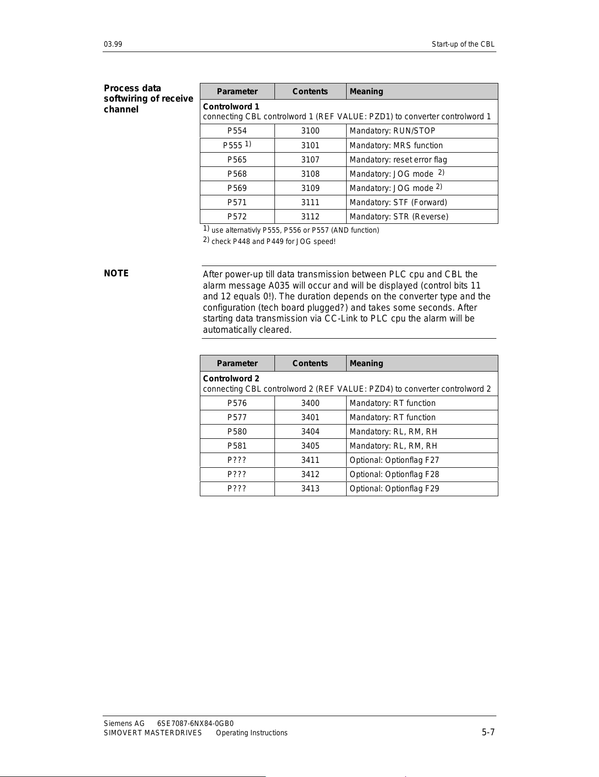
03.99 Start-up of the CBL
Siemens AG 6SE7087-6NX84-0GB0
SIMOVERT MASTERDRIVES Operating Instructions 5-7
Parameter Contents Meaning
Controlword 1
connecting CBL controlword 1 (REF VALUE: PZD1) to converter controlword 1
P554 3100 Mandatory: RUN/STOP
P555
1)
3101 Mandatory: MRS function
P565 3107 Mandatory: reset error flag
P568 3108 Mandatory: JOG mode
2)
P569 3109 Mandatory: JOG mode
2)
P571 3111 Mandatory: STF (Forward)
P572 3112 Mandatory: STR (Reverse)
1)
use alternativly P555, P556 or P557 (AND function)
2)
check P448 and P449 for JOG speed!
After power-up till data transmission between PLC cpu and CBL the
alarm message A035 will occur and will be displayed (control bits 11
and 12 equals 0!). The duration depends on the converter type and the
configuration (tech board plugged?) and takes some seconds. After
starting data transmission via CC-Link to PLC cpu the alarm will be
automatically cleared.
Parameter Contents Meaning
Controlword 2
connecting CBL controlword 2 (REF VALUE: PZD4) to converter controlword 2
P576 3400 Mandatory: RT function
P577 3401 Mandatory: RT function
P580 3404 Mandatory: RL, RM, RH
P581 3405 Mandatory: RL, RM, RH
P??? 3411 Optional: Optionflag F27
P??? 3412 Optional: Optionflag F28
P??? 3413 Optional: Optionflag F29
Process data
softwiring of receive
channel
NOTE
All manuals and user guides at all-guides.com
Page 56
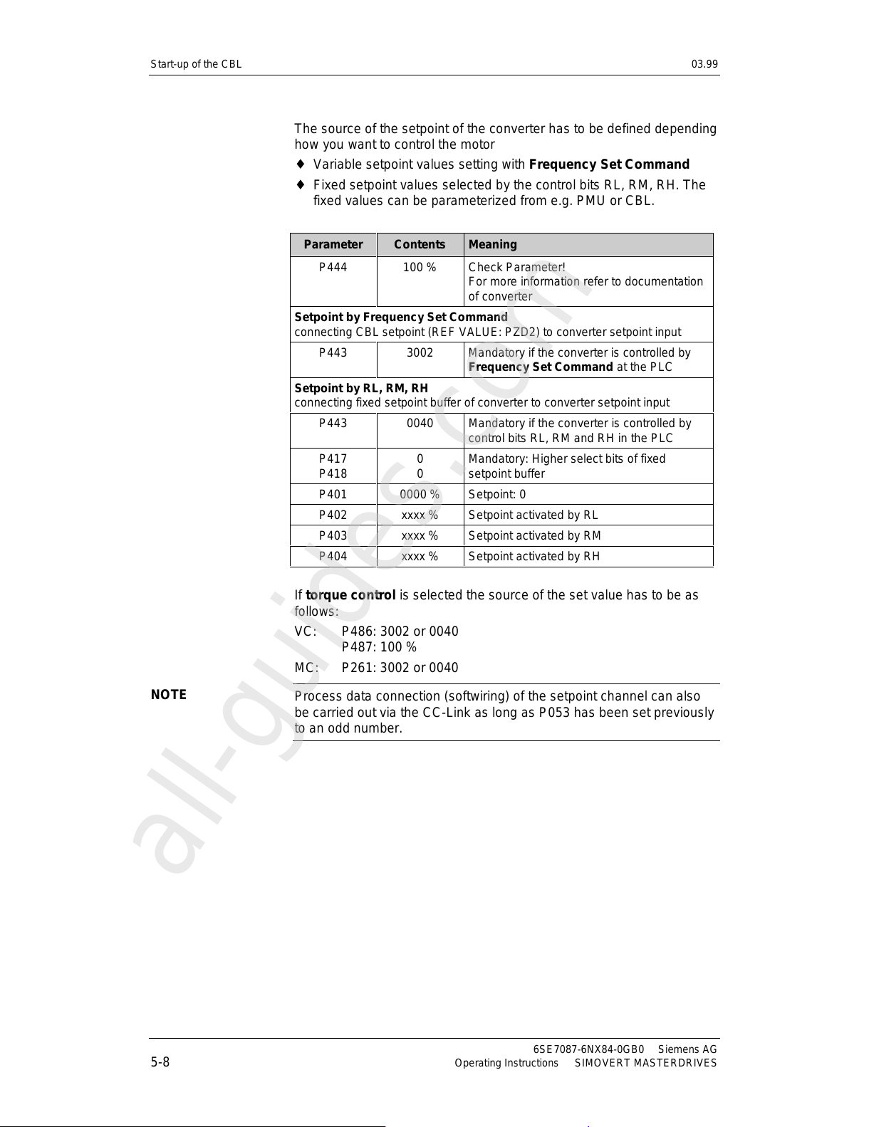
Start-up of the CBL 03.99
6SE7087-6NX84-0GB0 Siemens AG
5-8 Operating Instructions SIMOVERT MASTERDRIVES
The source of the setpoint of the converter has to be defined depending
how you want to control the motor
♦
Variable setpoint values setting with Frequency Set Command
♦
Fixed setpoint values selected by the control bits RL, RM, RH. The
fixed values can be parameterized from e.g. PMU or CBL.
Parameter Contents Meaning
P444 100 % Check Parameter!
For more information refer to documentation
of converter
Setpoint by Frequency Set Command
connecting CBL setpoint (REF VALUE: PZD2) to converter setpoint input
P443 3002 Mandatory if the converter is controlled by
Frequency Set Command at the PLC
Setpoint by RL, RM, RH
connecting fixed setpoint buffer of converter to converter setpoint input
P443 0040 Mandatory if the converter is controlled by
control bits RL, RM and RH in the PLC
P417
P418
0
0
Mandatory: Higher select bits of fixed
setpoint buffer
P401 0000 % Setpoint: 0
P402 xxxx % Setpoint activated by RL
P403 xxxx % Setpoint activated by RM
P404 xxxx % Setpoint activated by RH
If torque control is selected the source of the set value has to be as
follows:
VC: P486: 3002 or 0040
P487: 100 %
MC: P261: 3002 or 0040
Process data connection (softwiring) of the setpoint channel can also
be carried out via the CC-Link as long as P053 has been set previously
to an odd number.
NOTE
All manuals and user guides at all-guides.com
all-guides.com
Page 57
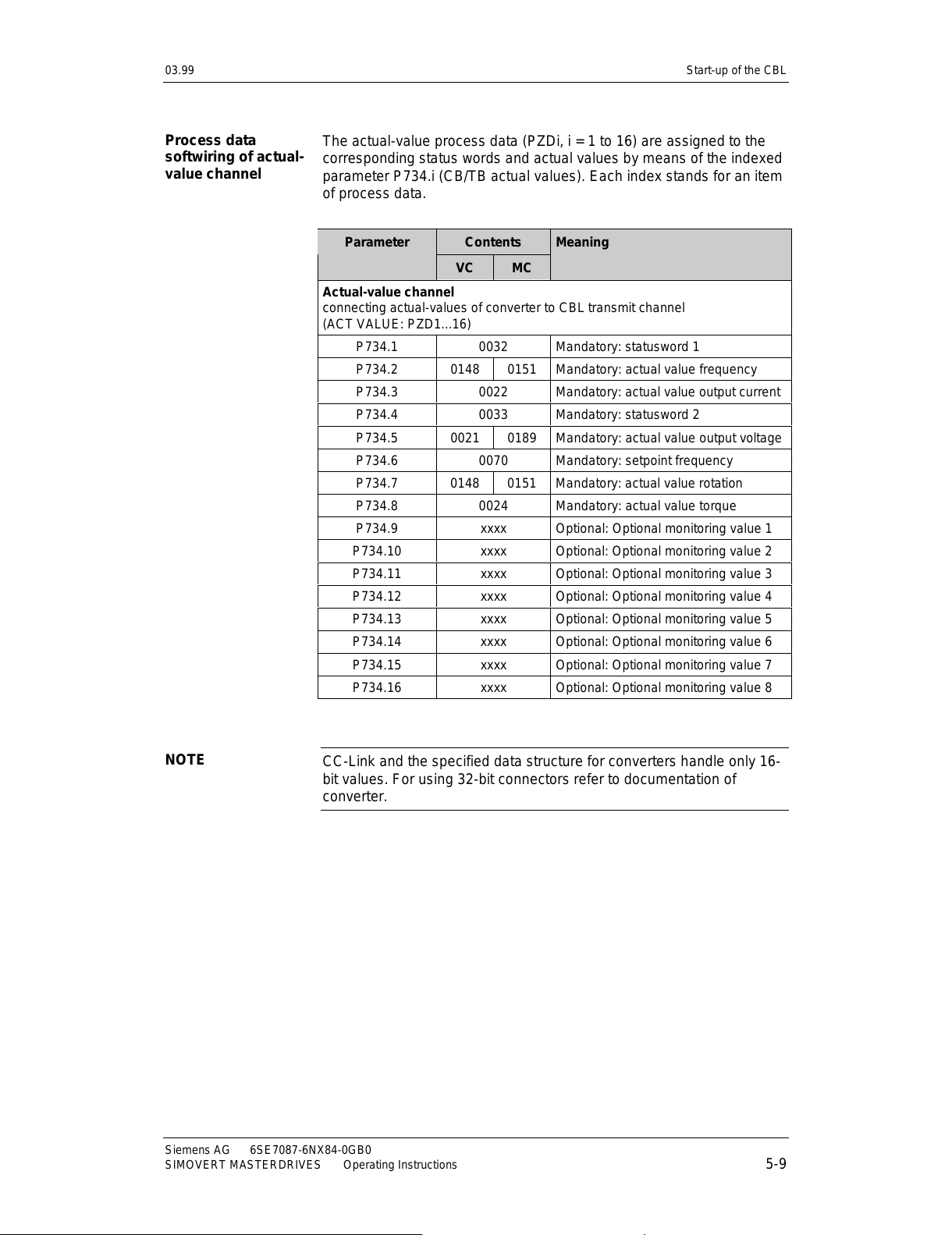
03.99 Start-up of the CBL
Siemens AG 6SE7087-6NX84-0GB0
SIMOVERT MASTERDRIVES Operating Instructions 5-9
The actual-value process data (PZDi, i = 1 to 16) are assigned to the
corresponding status words and actual values by means of the indexed
parameter P734.i (CB/TB actual values). Each index stands for an item
of process data.
ContentsParameter
VC MC
Meaning
Actual-value channel
connecting actual-values of converter to CBL transmit channel
(ACT VALUE: PZD1...16)
P734.1 0032 Mandatory: statusword 1
P734.2 0148 0151 Mandatory: actual value frequency
P734.3 0022 Mandatory: actual value output current
P734.4 0033 Mandatory: statusword 2
P734.5 0021 0189 Mandatory: actual value output voltage
P734.6 0070 Mandatory: setpoint frequency
P734.7 0148 0151 Mandatory: actual value rotation
P734.8 0024 Mandatory: actual value torque
P734.9 xxxx Optional: Optional monitoring value 1
P734.10 xxxx Optional: Optional monitoring value 2
P734.11 xxxx Optional: Optional monitoring value 3
P734.12 xxxx Optional: Optional monitoring value 4
P734.13 xxxx Optional: Optional monitoring value 5
P734.14 xxxx Optional: Optional monitoring value 6
P734.15 xxxx Optional: Optional monitoring value 7
P734.16 xxxx Optional: Optional monitoring value 8
CC-Link and the specified data structure for converters handle only 16-
bit values. For using 32-bit connectors refer to documentation of
converter.
Process data
softwiring of actual-
value channel
NOTE
All manuals and user guides at all-guides.com
Page 58

All manuals and user guides at all-guides.com
Page 59
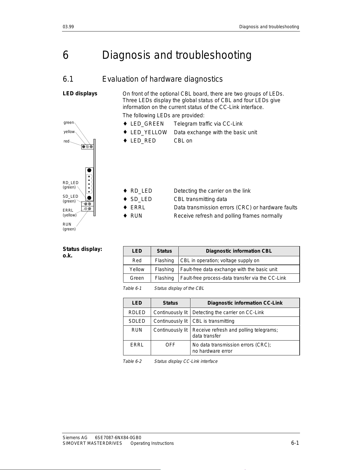
03.99 Diagnosis and troubleshooting
Siemens AG 6SE7087-6NX84-0GB0
SIMOVERT MASTERDRIVES Operating Instructions 6-1
6 Diagnosis and troubleshooting
6.1 Evaluation of hardware diagnostics
On front of the optional CBL board, there are two groups of LEDs.
Three LEDs display the global status of CBL and four LEDs give
information on the current status of the CC-Link interface.
The following LEDs are provided:
♦
LED_GREEN Telegram traffic via CC-Link
♦
LED_YELLOW Data exchange with the basic unit
♦
LED_RED CBL on
♦
RD_LED Detecting the carrier on the link
♦
SD_LED CBL transmitting data
♦
ERRL Data transmission errors (CRC) or hardware faults
♦
RUN Receive refresh and polling frames normally
LED Status Diagnostic information CBL
Red Flashing CBL in operation; voltage supply on
Yellow Flashing Fault-free data exchange with the basic unit
Green Flashing Fault-free process-data transfer via the CC-Link
Table 6-1 Status display of the CBL
LED Status Diagnostic information CC-Link
RDLED Continuously lit Detecting the carrier on CC-Link
SDLED Continuously lit CBL is transmitting
RUN Continuously lit Receive refresh and polling telegrams;
data transfer
ERRL OFF No data transmission errors (CRC);
no hardware error
Table 6-2 Status display CC-Link interface
LED displays
green
yellow
red
RD_LED
(green)
SD_LED
(green)
ERRL
(yellow)
RUN
(green)
Status display:
o.k.
All manuals and user guides at all-guides.com
Page 60

Diagnosis and troubleshooting 03.99
6SE7087-6NX84-0GB0 Siemens AG
6-2 Operating Instructions SIMOVERT MASTERDRIVES
During normal operation, the three CBL status LEDs (red, yellow and
green) light up synchronously and for the same length of time
(flashing)!
The stationary status of an LED (ON or OFF) indicates an unusual
operating status (parameterization phase or fault!)
During normal operation, the green CC-Link-LEDs are continuously lit.
The yellow one is off!
Diagnostic sequence:
❍ LED off
✹ LED flashing
● LED continuous lit
- LED information irrelevant
CBL status LEDs CC-Link interface LEDs Refer to
RED YELLOW GREEN RDLED SDLED RUNLED ERRLED
❍
- --- - -
●
- --- - -
Case 1
✹❍ ❍
-- - -Case 2
✹❍ ●
-- - -Case 3
✹● ❍
-- - -Case 4
✹● ●
-- - -Case 5
✹✹ ❍❍
- - - Case 6
✹✹ ❍●❍
--Case 7
✹✹ ❍●● ❍
- Case 8
✹✹ ●●● ●
- Case 9
-- --- -
✹
Case 10
✹✹ ✹●● ● ❍
o.k.
Table 6-3 Diagnostic sequence
NOTE
Diagnostic
sequence
All manuals and user guides at all-guides.com
Page 61

03.99 Diagnosis and troubleshooting
Siemens AG 6SE7087-6NX84-0GB0
SIMOVERT MASTERDRIVES Operating Instructions 6-3
Diagnostic steps:
LED Status Diagnostic information CBL
Red ON or OFF
Yellow -
Green -
CU, Tech-board or CBL is defective. Error
occured on CBL
Check:
• Connection between CBL and other boards
• Restart converter with power-down /-up
• Earth/protective conductor (EMC-faults)
Table 6-4 Fault display: Faults on CBL
LED Status Diagnostic information CBL
Red Flashing
Yellow OFF
Green OFF
CU, Tech board or CBL is defective.
Communication error between base board and
CBL
Check:
• Connection between CBL and other boards
• Restart converter with power-down /-up
• Earth/protective conductor (EMC-faults)
Table 6-5 Display during operation: Communication error at DPRAM
LED Status Diagnostic information CBL
Red Flashing
Yellow OFF
Green Continuously lit
CBL is waiting for start of parameterization /
initialization by the converter / inverter. This
sequence is automatically started by CU after
power-up and re-parameterizing.
CBL will stay in this status for some seconds till
CU is initialized.
Table 6-6 Display during operation: CBL is waiting for parameterization
LED Status Diagnostic information CC-Link
Red Flashing
Yellow Continuously lit
Green OFF
CBL is waiting for completion of
parameterization / initialization by the
converter / inverter.
Normally this state is so fast handled, that this
LED status can’t be seen.
Table 6-7 Display during operation: CBL is waiting for acknowledge of
parameterization
Case 1
Case 2
Case 3
Case 4
All manuals and user guides at all-guides.com
all-guides.com
Page 62

Diagnosis and troubleshooting 03.99
6SE7087-6NX84-0GB0 Siemens AG
6-4 Operating Instructions SIMOVERT MASTERDRIVES
LED Status Diagnostic information CBL
Red Flashing
Yellow Continuously lit
Green Continuously lit
CBL is fetching the scaling parameters from
CU.
CBL will stay in this status for some seconds. It
depends on the configuration. If an tech board
is plugged, it takes some more time.
If CBL don’t leave this status look for alarm
messages A081...A086.
Check:
• CB-Parameter P715...P718
• Parameters which are selected by
P715...P718
• Tech board and CU
Table 6-8 Display during operation: CBL fetches scaling parameters
LED Status Diagnostic information CBL
Red Flashing
Yellow Flashing
Green OFF
CBL now parameterized and has fetched the
scaling parameters. The CC-Link interface is
initialized.
Check CC-Link interface LEDs
Table 6-9 Display during operation: CC-Link initialized
Now it is assumed that the CBL-LEDs red and yellow are synchronous
flashing.
LED Status Diagnostic information CC-Link
RDLED OFF
SDLED OFF
RUNLED OFF
ERRLED OFF
CBL detects no carrier at CC-Link (signal
edges not detected);
check connection to CC-Link
Check the connector, correct connection of
signals DA, DB, DG and SLD (at CBL and CC-
Link master)
Table 6-10 Fault display during operation: No carrier detected
Case 5
Case 6
All manuals and user guides at all-guides.com
Page 63

03.99 Diagnosis and troubleshooting
Siemens AG 6SE7087-6NX84-0GB0
SIMOVERT MASTERDRIVES Operating Instructions 6-5
LED Status Diagnostic information CC-Link
RDLED ON
SDLED OFF
RUNLED OFF
ERRLED OFF
CBL detects carrier at CC-Link but doesn’t
answer
Check:
• Data transmission rate in P711
(same as CC-Link master?)
• CC-Link station number in P918 (sam e as
configured in PLC programming software)
• Station address already existent
• PLC network configuration: remote device
station, occupies 1 station, with station
number like P918
Table 6-11 Fault display during operation: NO answer of CBL to CC-Link master
LED Status Diagnostic information CC-Link
RDLED ON
SDLED ON
RUNLED OFF
ERRLED OFF
CBL receives and sends frames
Check:
• PLC network configuration: remote device
station, occupies 1 station, with station
number like P918
Table 6-12 Fault display during operati on: NO RUNLED at CB L
LED Status Diagnostic information CC-Link
RDLED ON
SDLED ON
RUNLED ON
ERRLED OFF
CBL communicates correctly on CC-Link! O.k.
Check CBL status LEDs!
Table 6-13 Display during operation: CB L communic ates on CC-Link
Now the three green CC-Link status LEDs continuously lit. Check the
green LED of CBL status.
LED Status Diagnostic information CBL
Red Flashing
Yellow Flashing
Green Continuously lit
CBL communicates correctly! But there is no
data transfer with PLC cpu!
Check:
• PLC cpu: status "STOP" or "FAULT"?
PLC cpu has to be at "RUN"!
• PLC cpu status "RUN" and CBL is waiting
for handling the initial process sequence
by the PLC software (look for the request
and completion flag in CC-Link inverter data
structure)
Table 6-14 Display during operation: No data t ransf er wit h PLC cpu
Case 7
Case 8
Case 9
All manuals and user guides at all-guides.com
Page 64
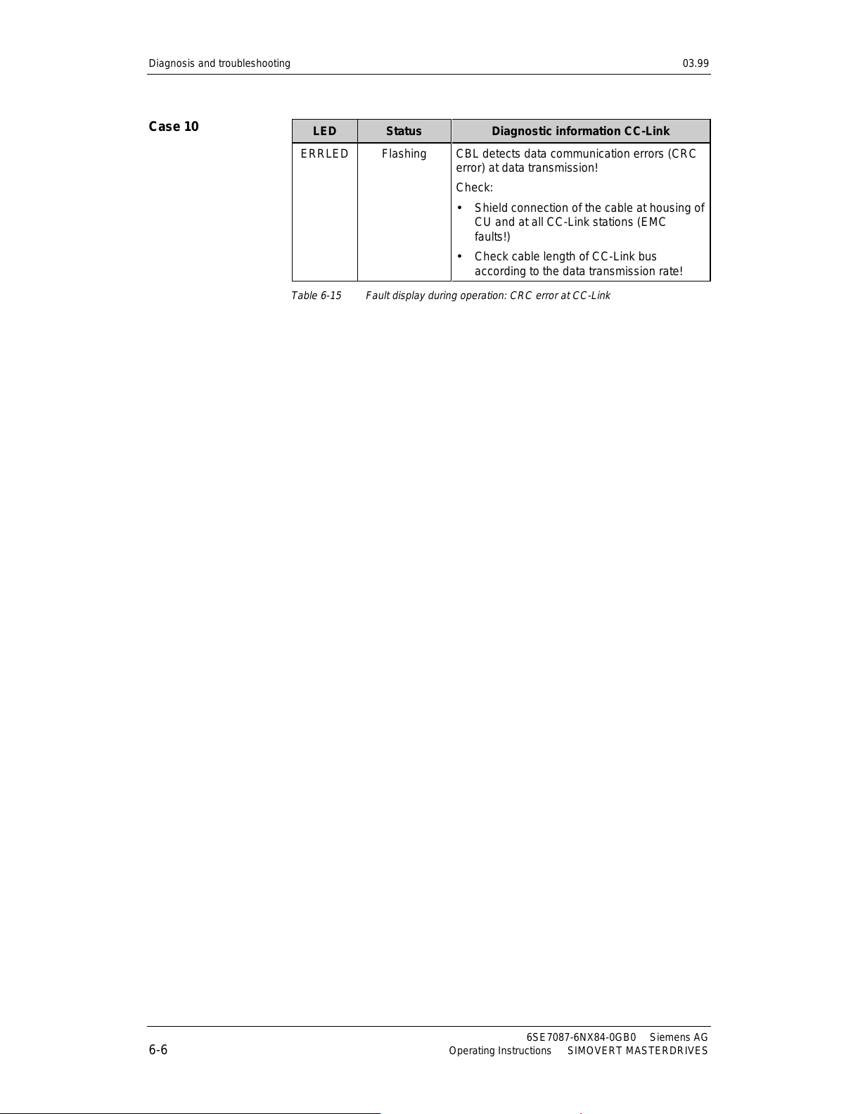
Diagnosis and troubleshooting 03.99
6SE7087-6NX84-0GB0 Siemens AG
6-6 Operating Instructions SIMOVERT MASTERDRIVES
LED Status Diagnostic information CC-Link
ERRLED Flashing CBL detects data communication errors (CRC
error) at data transmission!
Check:
• Shield connection of the cable at housing of
CU and at all CC-Link stations (EMC
faults!)
• Check cable length of CC-Link bus
according to the data transmission rate!
Table 6-15 Fault display during operati on: CRC error at CC-Li nk
Case 10
All manuals and user guides at all-guides.com
Page 65
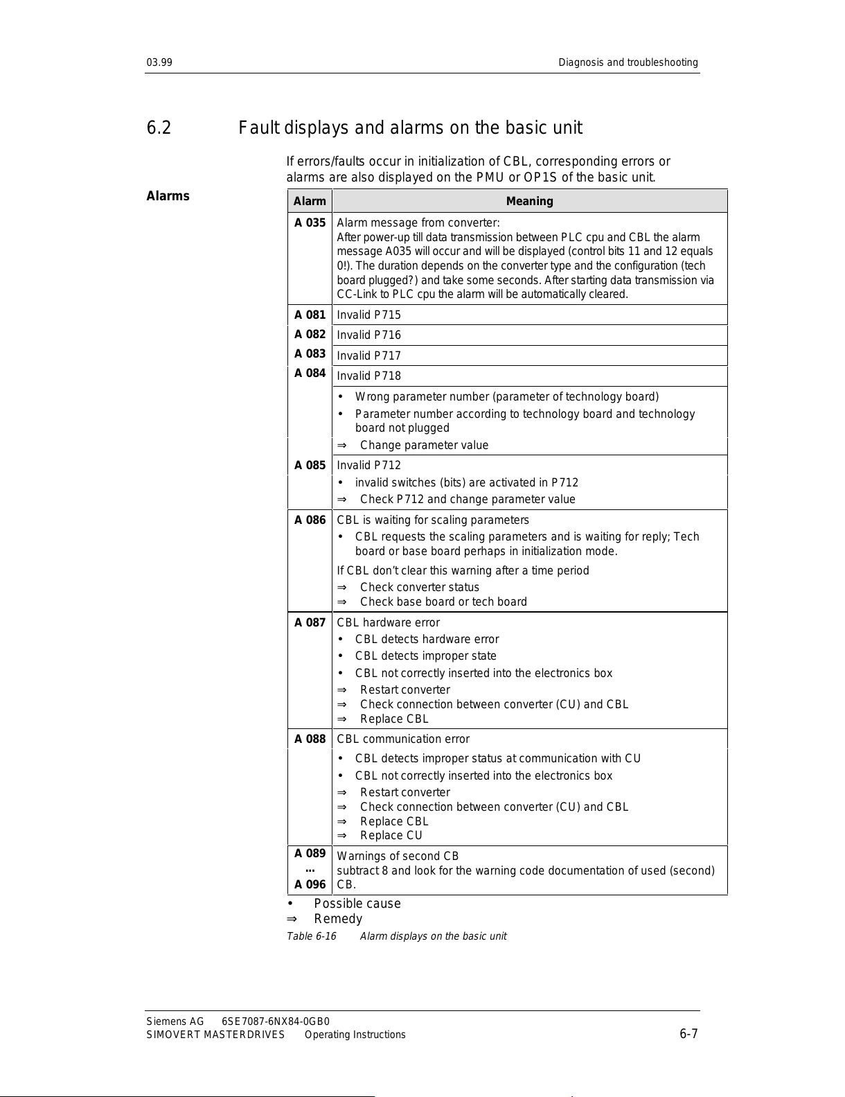
03.99 Diagnosis and troubleshooting
Siemens AG 6SE7087-6NX84-0GB0
SIMOVERT MASTERDRIVES Operating Instructions 6-7
6.2 Fault displays and alarms on the basic unit
If errors/faults occur in initialization of CBL, corresponding errors or
alarms are also displayed on the PMU or OP1S of the basic unit.
Alarm Meaning
A 035 Alarm message from convert er:
After power-up till data transmission between PLC cpu and CBL the alarm
message A035 will occur and will be displayed (control bits 11 and 12 equals
0!). The duration depends on the converter type and the configuration (tech
board plugged?) and take some seconds. After starting data transmission via
CC-Link to PLC cpu the alarm will be automatically cleared.
Invalid P715
Invalid P716
Invalid P717
A 081
A 082
A 083
A 084
Invalid P718
• Wrong parameter number (parameter of technology board)
• Parameter number according to technology board and technology
board not plugged
⇒ Change parameter value
A 085 Invalid P712
• invalid switches (bits) are activated in P712
⇒ Check P712 and change parameter value
A 086 CBL is waiting for scaling parameters
• CBL requests the scaling parameters and is waiting for reply; Tech
board or base board perhaps in initialization mode.
If CBL don’t clear this warning after a time period
⇒ Check converter status
⇒ Check base board or tech board
A 087 CBL hardware error
• CBL detects hardware error
• CBL detects improper state
• CBL not correctly inserted into the electronics box
⇒ Restart converter
⇒ Check connection between converter (CU) and CBL
⇒ Replace CBL
A 088 CBL communication error
• CBL detects improper status at communication with CU
• CBL not correctly inserted into the electronics box
⇒ Restart converter
⇒ Check connection between converter (CU) and CBL
⇒ Replace CBL
⇒ Replace CU
A 089
...
A 096
Warnings of second CB
subtract 8 and look for the warning code documentation of used (second)
CB.
• Possible cause
⇒ Remedy
Table 6-16 Alarm displays on the basic unit
Alarms
All manuals and user guides at all-guides.com
Page 66
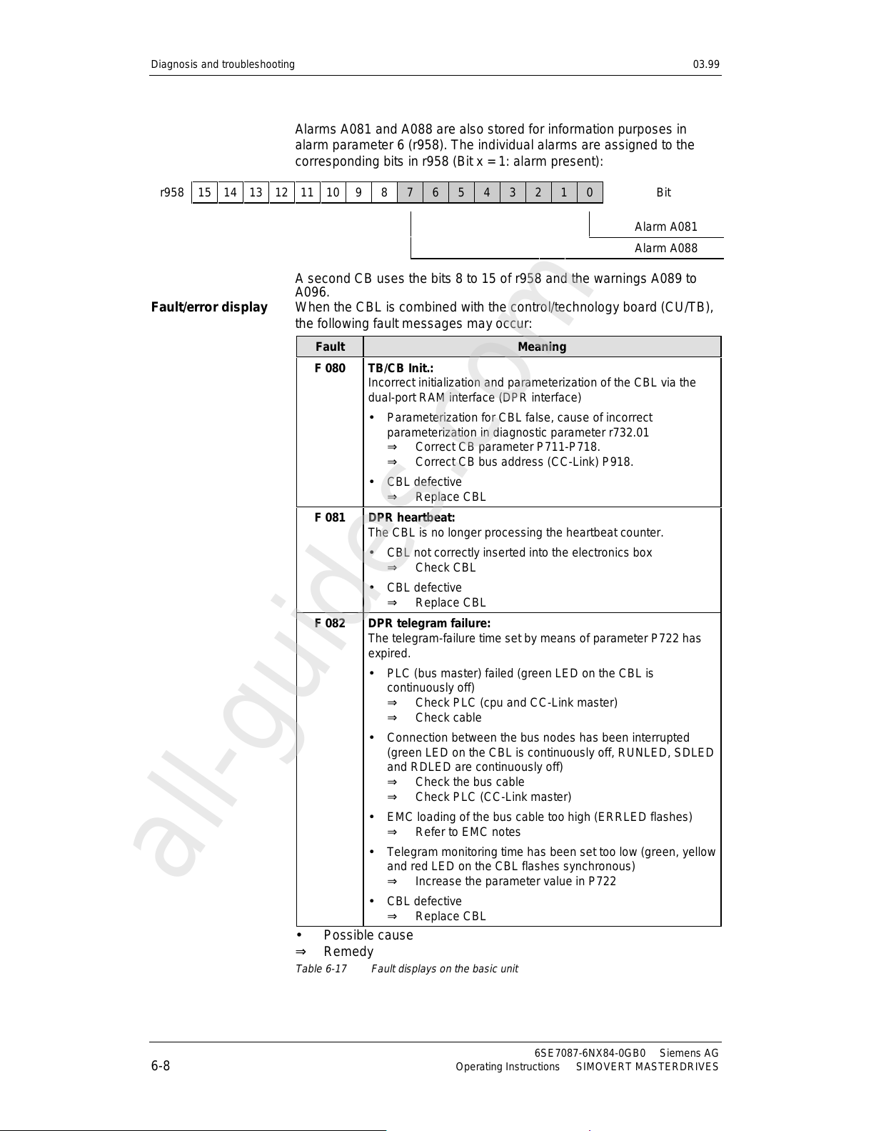
Diagnosis and troubleshooting 03.99
6SE7087-6NX84-0GB0 Siemens AG
6-8 Operating Instructions SIMOVERT MASTERDRIVES
Alarms A081 and A088 are also stored for information purposes in
alarm parameter 6 (r958). The individual alarms are assigned to the
corresponding bits in r958 (Bit x = 1: alarm present):
r958 15 14 13 12 11 10 9 8 7 6 5 4 3 2 1 0 Bit
Alarm A081
Alarm A088
A second CB uses the bits 8 to 15 of r958 and the warnings A089 to
A096.
When the CBL is combined with the control/technology board (CU/TB),
the following fault messages may occur:
Fault Meaning
F 080 TB/CB Init.:
Incorrect initialization and parameterization of the CBL via the
dual-port RAM interface (DPR interface)
• Parameterization for CBL false, cause of incorrect
parameterization in diagnostic parameter r732.01
⇒ Correct CB parameter P711-P718.
⇒ Correct CB bus address (CC-Link) P918.
• CBL defective
⇒ Replace CBL
F 081 DPR heartbeat:
The CBL is no longer processing the heartbeat counter.
• CBL not correctly inserted into the electronics box
⇒ Check CBL
• CBL defective
⇒ Replace CBL
F 082 DPR telegram failure:
The telegram-failure time set by means of parameter P722 has
expired.
• PLC (bus master) failed (green LED on the CBL is
continuously off)
⇒ Check PLC (cpu and CC-Link master)
⇒ Check cable
• Connection between the bus nodes has been interrupted
(green LED on the CBL is continuously off, RUNLED, SDLED
and RDLED are continuously off)
⇒ Check the bus cable
⇒ Check PLC (CC-Link master)
• EMC loading of the bus cable too high (ERRLED flashes)
⇒ Refer to EMC notes
• Telegram monitoring time has been set too low (green, yellow
and red LED on the CBL flashes synchronous)
⇒ Increase the parameter value in P722
• CBL defective
⇒ Replace CBL
• Possible cause
⇒ Remedy
Table 6-17 Fault displays on the basic unit
Fault/error display
All manuals and user guides at all-guides.com
all-guides.com
Page 67
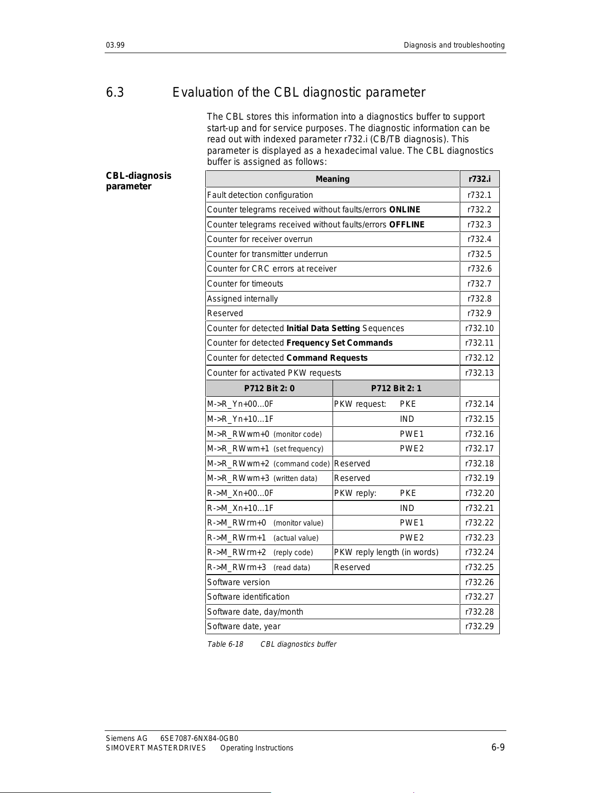
03.99 Diagnosis and troubleshooting
Siemens AG 6SE7087-6NX84-0GB0
SIMOVERT MASTERDRIVES Operating Instructions 6-9
6.3 Evaluation of the CBL diagnostic parameter
The CBL stores this information into a diagnostics buffer to support
start-up and for service purposes. The diagnostic information can be
read out with indexed parameter r732.i (CB/TB diagnosis). This
parameter is displayed as a hexadecimal value. The CBL diagnostics
buffer is assigned as follows:
Meaning r732.i
Fault detection configuration r732.1
Counter telegrams received without faults/errors ONLINE r732.2
Counter telegrams received without faults/errors OFFLINE r732.3
Counter for receiver overrun r732.4
Counter for transmitter underrun r732.5
Counter for CRC errors at receiver r732.6
Counter for timeouts r732.7
Assigned internally r732.8
Reserved r732.9
Counter for detected Initial Data Setting Sequences r732.10
Counter for detected Frequency Set Commands r732.11
Counter for detected Command Requests r732.12
Counter for activated PKW requests r732.13
P712 Bit 2: 0 P712 Bit 2: 1
M->R_Yn+00...0F PKW request: PKE r732.14
M->R_Yn+10...1F IND r732.15
M->R_RWwm+0 (monitor code) PWE1 r732.16
M->R_RWwm+1 (set frequency) PWE2 r732.17
M->R_RWwm+2 (command code) Reserved r732.18
M->R_RWwm+3 (written data) Reserved r732.19
R->M_Xn+00...0F PKW reply: PKE r732.20
R->M_Xn+10...1F IND r732.21
R->M_RWrm+0 (monitor value) PWE1 r732.22
R->M_RWrm+1 (actual value) PWE2 r732.23
R->M_RWrm+2 (reply code) PKW reply length (in words) r732.24
R->M_RWrm+3 (read data) Reserved r732.25
Software version r732.26
Software identification r732.27
Software date, day/month r732.28
Software date, year r732.29
Table 6-18 CBL diagnostics buffer
CBL-diagnosis
parameter
All manuals and user guides at all-guides.com
Page 68
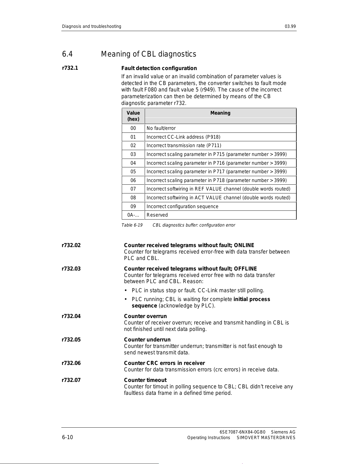
Diagnosis and troubleshooting 03.99
6SE7087-6NX84-0GB0 Siemens AG
6-10 Operating Instructions SIMOVERT MASTERDRIVES
6.4 Meaning of CBL diagnostics
Fault detection configuration
If an invalid value or an invalid combination of parameter values is
detected in the CB parameters, the converter switches to fault mode
with fault F080 and fault value 5 (r949). The cause of the incorrect
parameterization can then be determined by means of the CB
diagnostic parameter r732.
Value
(hex)
Meaning
00 No fault/error
01 Incorrect CC-Link address (P918)
02 Incorrect transmission rate (P711)
03 Incorrect scaling parameter in P715 (parameter number > 3999)
04 Incorrect scaling parameter in P716 (parameter number > 3999)
05 Incorrect scaling parameter in P717 (parameter number > 3999)
06 Incorrect scaling parameter in P718 (parameter number > 3999)
07 Incorrect softwiring in REF VALUE channel (double words routed)
08 Incorrect softwiring in ACT VALUE channel (double words routed)
09 Incorrect configuration sequence
0A-... Reserved
Table 6-19 CBL diagnostics buffer: configuration error
r732.02 Counter received telegrams without fault; ONLINE
Counter for telegrams received error-free with data transfer between
PLC and CBL.
r732.03 Counter received telegrams without fault; OFFLINE
Counter for telegrams received error free with no data transfer
between PLC and CBL. Reason:
•
PLC in status stop or fault. CC-Link master still polling.
•
PLC running; CBL is waiting for complete initial process
sequence (acknowledge by PLC).
r732.04 Counter overrun
Counter of receiver overrun; receive and transmit handling in CBL is
not finished until next data polling.
r732.05 Counter underrun
Counter for transmitter underrun; transmitter is not fast enough to
send newest transmit data.
r732.06 Counter CRC errors in receiver
Counter for data transmission errors (crc errors) in receive data.
r732.07 Counter timeout
Counter for timout in polling sequence to CBL; CBL didn’t receive any
faultless data frame in a defined time period.
r732.1
All manuals and user guides at all-guides.com
Page 69
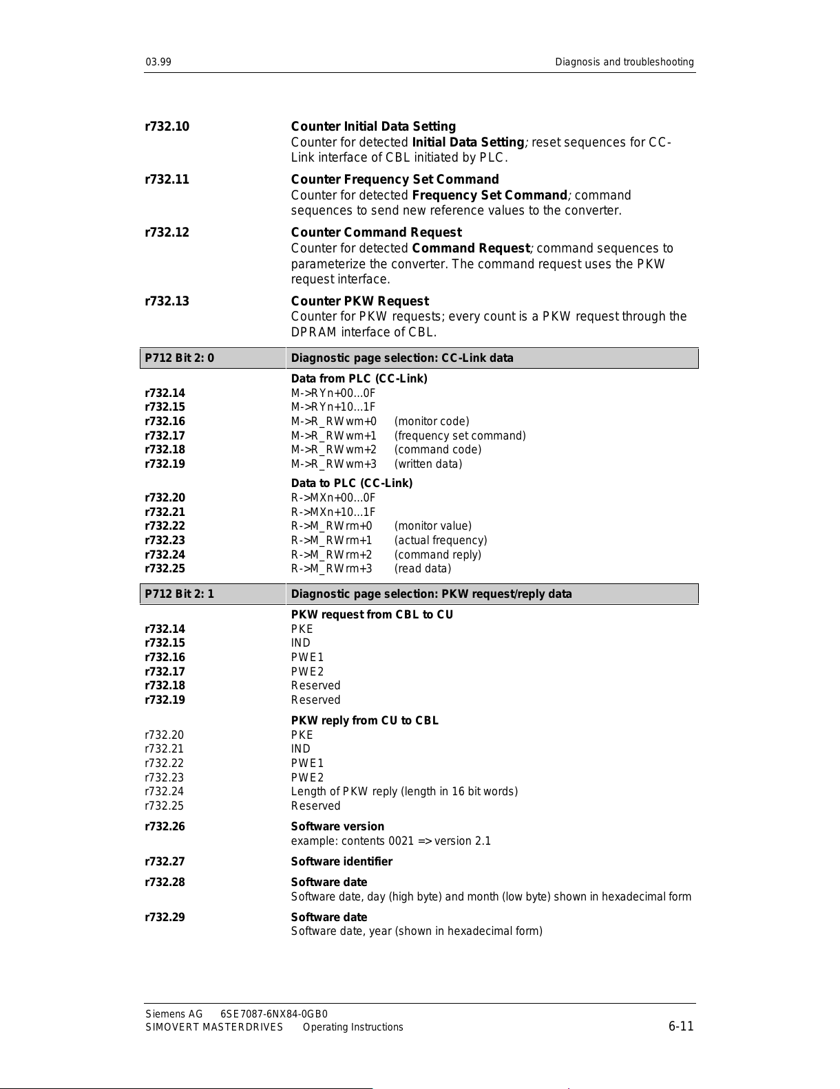
03.99 Diagnosis and troubleshooting
Siemens AG 6SE7087-6NX84-0GB0
SIMOVERT MASTERDRIVES Operating Instructions 6-11
r732.10 Counter Initial Data Setting
Counter for detected Initial Data Setting
;
reset sequences for CC-
Link interface of CBL initiated by PLC.
r732.11 Counter Frequency Set Command
Counter for detected Frequency Set Command
;
command
sequences to send new reference values to the converter.
r732.12 Counter Command Request
Counter for detected Command Request
;
command sequences to
parameterize the converter. The command request uses the PKW
request interface.
r732.13 Counter PKW Request
Counter for PKW requests; every count is a PKW request through the
DPRAM interface of CBL.
P712 Bit 2: 0 Diagnostic page selection: CC-Link data
r732.14
r732.15
r732.16
r732.17
r732.18
r732.19
Data from PLC (CC-Link)
M->RYn+00...0F
M->RYn+10...1F
M->R_RWwm+0 (monitor code)
M->R_RWwm+1 (frequency set command)
M->R_RWwm+2 (command code)
M->R_RWwm+3 (written data)
r732.20
r732.21
r732.22
r732.23
r732.24
r732.25
Data to PLC (CC-Link)
R->MXn+00...0F
R->MXn+10...1F
R->M_RWrm+0 (monitor value)
R->M_RWrm+1 (actual frequency)
R->M_RWrm+2 (command reply)
R->M_RWrm+3 (read data)
P712 Bit 2: 1 Diagnostic page selection: PKW request/reply data
r732.14
r732.15
r732.16
r732.17
r732.18
r732.19
PKW request from CBL to CU
PKE
IND
PWE1
PWE2
Reserved
Reserved
r732.20
r732.21
r732.22
r732.23
r732.24
r732.25
PKW reply from CU to CBL
PKE
IND
PWE1
PWE2
Length of PKW reply (length in 16 bit words)
Reserved
r732.26 Softw a re version
example: contents 0021 => version 2.1
r732.27 Software identifier
r732.28 Software date
Software date, day (high byte) and month (low byte) shown in hexadecimal form
r732.29 Software date
Software date, year (shown in hexadecimal form)
All manuals and user guides at all-guides.com
Page 70

All manuals and user guides at all-guides.com
Page 71
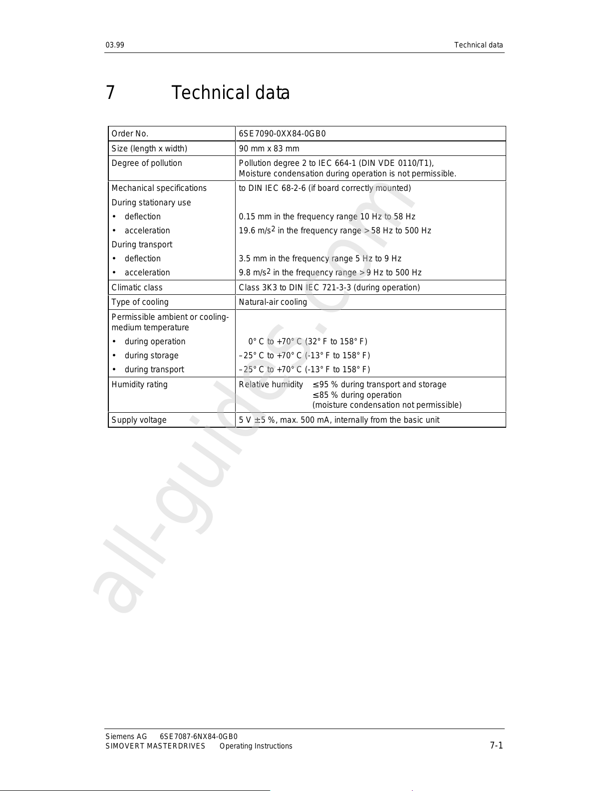
03.99 Technical data
Siemens AG 6SE7087-6NX84-0GB0
SIMOVERT MASTERDRIVES Operating Instructions 7-1
7 Technical data
Order No. 6SE7090-0XX84-0GB0
Size (length x width) 90 mm x 83 mm
Degree of pollution Pollution degree 2 to IEC 664-1 (DIN VDE 0110/T1),
Moisture condensation during operation is not permissible.
Mechanical specifications
During stationary use
• deflection
• acceleration
During transport
• deflection
• acceleration
to DIN IEC 68-2-6 (if board correctly mounted)
0.15 mm in the frequency range 10 Hz to 58 Hz
19.6 m/s
2
in the frequency range > 58 Hz to 500 Hz
3.5 mm in the frequency range 5 Hz to 9 Hz
9.8 m/s2 in the frequency range > 9 Hz to 500 Hz
Climatic class Class 3K3 to DIN IEC 721-3-3 (during operation)
Type of cooling Natural-air cooling
Permissible ambient or cooling-
medium temperature
• during operation
• during storage
• during transport
0° C to +70° C (32° F to 158° F)
–25° C to +70° C (-13° F to 158° F)
–25° C to +70° C (-13° F to 158° F)
Humidity rating
Relative humidity ≤ 95 % during transport and storage
≤ 85 % during operation
(moisture condensation not permissible)
Supply voltage 5 V ± 5 %, max. 500 mA, internally from the basic unit
All manuals and user guides at all-guides.com
all-guides.com
Page 72

All manuals and user guides at all-guides.com
Page 73
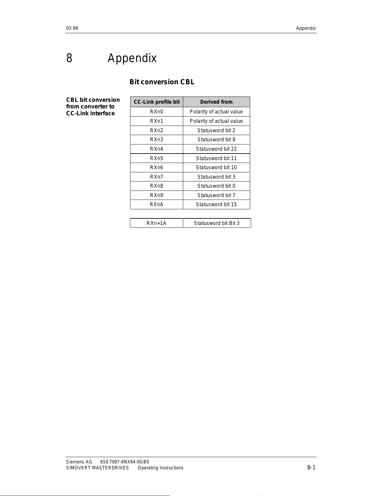
03.99 Appendix
Siemens AG 6SE7087-6NX84-0GB0
SIMOVERT MASTERDRIVES Operating Instructions 8-1
8 Appendix
Bit conversion CBL
CC-Link profile bit Derived from
RXn0 Polarity of actual value
RXn1 Polarity of actual value
RXn2 Statusword bit 2
RXn3 Statusword bit 8
RXn4 Statusword bit 22
RXn5 Statusword bit 11
RXn6 Statusword bit 10
RXn7 Statusword bit 3
RXn8 Statusword bit 0
RXn9 Statusword bit 7
RXnA Statusword bit 15
RXn+1A Statusword bit Bit 3
CBL bit conversion
from converter to
CC-Link interface
All manuals and user guides at all-guides.com
Page 74

Appendix 03.99
6SE7087-6NX84-0GB0 Siemens AG
8-2 Operating Instructions SIMOVERT MASTERDRIVES
Controlword bit Derived from
0STF XOR STR
1 NOT MRS
21
31
41
51
61
7 ERRF
8 JOG1
9 JOG2
10 1
11 STF, STR
12 See below
13 0
14 0
15 0
16 RT = 0 => 00
17 RT = 1 => 01
18 0
19 0
20 RH = 11, RM = 10,
21 RL = 01
22 0
23 1
24 1
25 1
26 0
27 F27
28 F28
29 F29
30 0
31 0
Remote IO Bits Controlword
STF STR Forward enable (Bit 11) Reverse Enable (Bit 12)
00 1 1
10 1 0
01 0 1
11 1 1
CBL bit conversion
from CC-Link
interface to
converter
All manuals and user guides at all-guides.com
Page 75
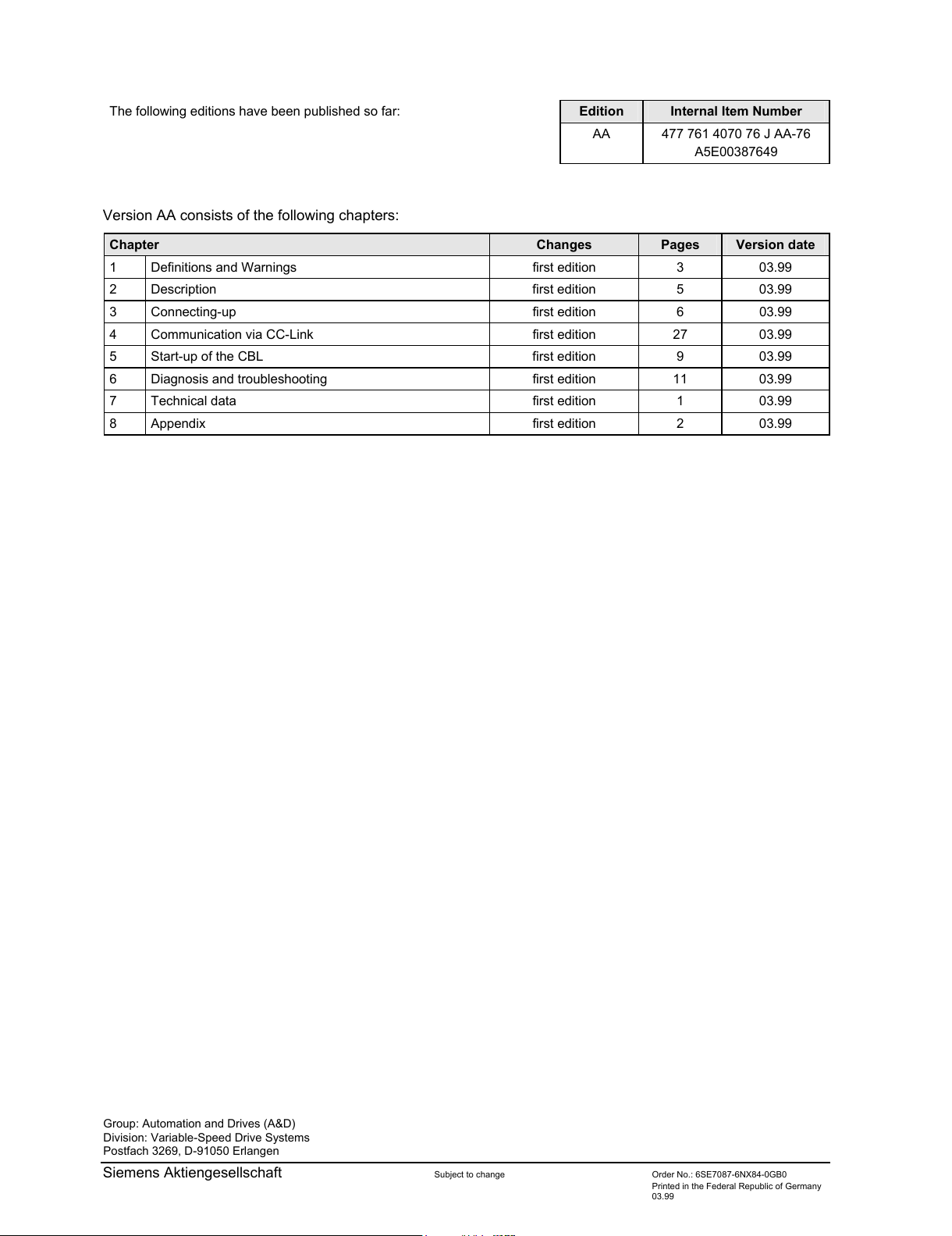
Group: Automation and Drives (A&D)
Division: Variable-Speed Drive Systems
Postfach 3269, D-91050 Erlangen
Siemens Aktiengesellschaft Subject to change Order No.: 6SE7087-6NX84-0GB0
Printed in the Federal Republic of Germany
03.99
The following editions have been published so far: Edition Internal Item Number
AA 477 761 4070 76 J AA-76
A5E00387649
Version AA consists of the following chapters:
Chapter Changes Pages Version date
1 Definitions and Warnings first edition 3 03.99
2 Description first edition 5 03.99
3 Connecting-up first edition 6 03.99
4 Communication via CC-Link first edition 27 03.99
5 Start-up of the CBL first edition 9 03.99
6 Diagnosis and troubleshooting first edition 11 03.99
7 Technical data first edition 1 03.99
8 Appendix first edition 2 03.99
All manuals and user guides at all-guides.com
 Loading...