


SIMOVERT MASTER DRIVES
Operating Instructions
Types J to M
DC-AC
Part 1
Edition: AB Order No.: 6SE7087-6BM70

General 12.96
Overview of the MASTER DRIVES Operating Instructions:
Operating Instructions consists of
Part 1 Part 2
6SE708_-_AD10 6SE708_-_AD70 6SE708_-_XX10
6SE708_-_AD20 6SE708_-_AD70 6SE708_-_XX20
6SE708_-_AD30 6SE708_-_AD70 6SE708_-_XX30
6SE708_-_BD10 6SE708_-_BD70 6SE708_-_XX10
6SE708_-_BD20 6SE708_-_BD70 6SE708_-_XX20
6SE708_-_BD30 6SE708_-_BD70 6SE708_-_XX30
6SE708_-_AH10 6SE708_-_AH70 6SE708_-_XX10
6SE708_-_AH20 6SE708_-_AH70 6SE708_-_XX20
6SE708_-_AH30 6SE708_-_AH70 6SE708_-_XX30
6SE708_-_BH10 6SE708_-_BH70 6SE708_-_XX10
6SE708_-_BH20 6SE708_-_BH70 6SE708_-_XX20
6SE708_-_BH30 6SE708_-_BH70 6SE708_-_XX30
6SE708_-_BM20 6SE708_-_BM70 6SE708_-_XX20
You will receive Parts 1 and 2 of the Operating Instructions when you use this Order No. Parts 1
and 2 can be individually ordered by specifying the particular Order No.
_-_ stands for the language code, e.g. 0-0 for German Editions.
The following foreign language Editions of these Operating Instructions are available:
Language German French Spanish Italian
Language code 0-0 7-7 7-8 7-2
These Operating Instructions are valid for software release V1.2.
The reproduction, transmission or use of this document or i ts
contents is not permitted without express writ ten authority.
Offenders will be liable for damages. All rights, including rights
created by patent grant or registrati on of a utility model or design,
are reserved.
We have checked the content s of this document to ens ure t hat
they coincide with the described hardware and software.
However, differences cannot be completely excluded, so that we
do not accept any guarantee for c om pl ete conformance.
However, the information in t hi s document is regularly checked
and necessary corrections will inc l uded in subsequent editions.
We are grateful for any recommendati ons for improvement.
Siemens AG 1996 All rights reserved
SIMOVERT Registered Trade Mark

12.96 General
Contents
0 Definitions................................................................................................................................. 0-6
Safety and operating instructions for drive converters....................................................... 0-8
1 Description................................................................................................................................ 1-1
1.1 Applications................................................................................................................................ 1-1
1.2 Mode of operation ...................................................................................................................... 1-1
1.3 Operator control- and open-loop control possibilities................................................................. 1-2
1.4 Block diagram............................................................................................................................. 1-3
2 Transport, Unpacking, Installation......................................................................................... 2-1
2.1 Transport and unpacking............................................................................................................ 2-1
2.2 Storage....................................................................................................................................... 2-1
2.3 Mounting..................................................................................................................................... 2-2
2.4 Dimension drawings................................................................................................................... 2-4
3 Connecting-up.......................................................................................................................... 3-1
3.1 Power connections..................................................................................................................... 3-2
3.1.1 Protective conductor connection ................................................................................................ 3-4
3.2 Auxiliary power supply/main contactor or bypass contactor....................................................... 3-4
4 Operator control....................................................................................................................... 4-1
4.1 Operator control elements.......................................................................................................... 4-1
4.2 Displays
.................................................................................................................... 4-2
5 Maintenance.............................................................................................................................. 5-1
5.1 Maintenance requirements......................................................................................................... 5-1
5.2 Replacing components...............................................................................................................5-2
5.2.1 Replacing the fan........................................................................................................................ 5-2
5.2.2 Replacing the fuses.................................................................................................................... 5-2
5.2.3 Replacing the starting capacitor ................................................................................................. 5-3
5.2.4 Replacing the capacitor bank ..................................................................................................... 5-3
5.2.5 Replacing SML and SMU ........................................................................................................... 5-3
Siemens AG 6SE7087-6BM70
SIMOVERT MASTER DRIVES Operating Instructions
0-3

General 12.96
5.2.6 Removing and installing the module busbars.............................................................................5-4
5.2.6.1 Replacing the balancing resistor.................................................................................................5-4
5.2.7 Replacing boards........................................................................................................................ 5-5
5.2.7.1 Replacing the IVI / IPI (type of construction M) .......................................................................... 5-5
5.2.7.2 Replacing the VDU and VDU resistor......................................................................................... 5-6
5.2.7.3 Replacing the PSU..................................................................................................................... 5-6
5.2.7.4 Replacing the IGD...................................................................................................................... 5-6
5.2.8 Replacing the snubber resistor...................................................................................................5-7
5.2.8.1 Replacing the IGBT modules...................................................................................................... 5-7
5.2.8.2 Replacing boards in the electronics box..................................................................................... 5-8
5.2.8.3 Replacing the PMU (Parameterization Unit)............................................................................... 5-8
6 Options...................................................................................................................................... 6-1
6.1 Options which can be integrated into the electronics box........................................................... 6-1
6.2 Interface boards.......................................................................................................................... 6-3
6.3 Power supplies ........................................................................................................................... 6-3
6.4 Isolating amplifiers...................................................................................................................... 6-4
6.5 Power section.............................................................................................................................6-4
6.5.1 Output reactor, dv/dt filter........................................................................................................... 6-5
6.5.1.1 Output reactor............................................................................................................................. 6-6
6.5.1.2 dv/dt filter....................................................................................................................................6-7
6.5.1.3 Selection criteria for the output reactor or dv/dt filter.................................................................. 6-8
6.6 Bypass- and output contactor..................................................................................................... 6-9
6.6.1 Bypass contactor (electrical DC link coupling)............................................................................ 6-9
6.6.1.1 Bypass contactor without I/R unit ............................................................................................... 6-9
6.6.1.2 Bypass contactor with I/R unit .................................................................................................. 6-10
6.6.1.3 Connecting and disconnecting individual converters to the DC bus......................................... 6-11
6.6.2 Output contactor....................................................................................................................... 6-11
6.7 Operator control........................................................................................................................ 6-12
7 Spare Parts................................................................................................................................ 7-1
7.1 Converter 510 V to 620 V DC..................................................................................................... 7-1
7.2 Converter 675 V to 780 V DC..................................................................................................... 7-4
7.3 Converter 890 V to 930 V DC..................................................................................................... 7-9
8 Environmental friendliness.....................................................................................................8-1
9 Technical Data.......................................................................................................................... 9-1
9.1 De-rating for an increased cooling medium temperature ...........................................................9-7
9.2 De-rating at installation altitudes > 1000 m above sea level....................................................... 9-7
0-4 Siemens AG 6SE7087-6BM70
SIMOVERT MASTER DRIVES Operating Instructions

12.96 General
10 Appendix................................................................................................................................. 10-1
10.1 Index......................................................................................................................................... 10-1
10.2 List of abbreviations.................................................................................................................. 10-2
11 Addresses............................................................................................................................... 11-1
12 Certificates.............................................................................................................................. 12-1
Siemens AG 6SE7087-6BM70
SIMOVERT MASTER DRIVES Operating Instructions
0-5

General 12.96
0 Definitions
QUALIFIED PERSONAL
•
For the purpose of these instructions and product labels, a "Qualified person" is someone who is familiar with
the installation, mounting, start-up and operation of the equipment and the hazards involved. He or she must
have the following qualifications:
1. Trained and authorized to energize, de-energize, clear, ground and tag circuits and equipment in
accordance with established safety procedures.
2. Trained in the proper care and use of protective equipment in accordance with established safety
procedures.
3. Trained in rendering first aid.
DANGER
•
For the purpose of these instructions and product labels, "Danger" indicates death, severe personal injury or
substantial property damage will result if proper precautions are not taken.
WARNING
•
For the purpose of these instructions and product labels, "Warning" indicates death, severe personal injury or
property damage can result if proper precautions are not taken.
CAUTION
•
For the purpose of these instructions and product labels, "Caution" indicates that minor personal injury or
material damage can result if proper precautions are not taken.
NOTE
•
For the purpose of these instructions, "Note" indicates information about the product or the respective part of
the Instruction Manual which is essential to highlight.
NOTE
These instructions do not purport to cover all details or variations in equipment, nor to provide for every
possible contingency to be met in connection with installation, operation or maintenance.
Should further information be desired or should particular problems arise which are not covered sufficiently for
the purchaser’s purposes, the matter should be referred to the local Siemens sales office.
The contents of this Instruction Manual shall not become part of or modify any prior or existing agreement,
committment or relationship. The sales contract contains the entire obligation of Siemens. The warranty
contained in the contract between the parties is the sole warranty of Siemens. Any statements contained herein
do not create new warranties or modify the existing warranty.
0-6 Siemens AG 6SE7087-6BM70
SIMOVERT MASTER DRIVES Operating Instructions
12.96 General
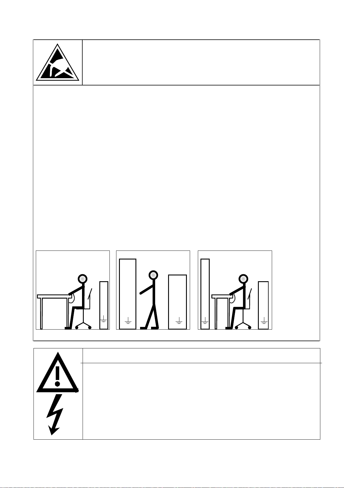
CAUTION
Components which can be destroyed by electrostatic discharge (ESD)
The converters contain components which can be destroyed by electrostatic discharge. These components can
be easily destroyed if not carefully handled. If you have to handle electronic boards please observe the
following:
Electronic boards should only be touched when absolutely necessary.
♦
The human body must be electrically discharged before touching an electronic board
♦
Boards must not come into contact with highly insulating materials - e.g. plastic foils, insulated desktops,
♦
articles of clothing manufactured from man-made fibers
Boards must only be placed on conductive surfaces
♦
When soldering, the soldering iron tip must be grounded
♦
Boards and components should only be stored and transported in conductive packaging (e.g. metalized
♦
plastic boxes, metal containers)
If the packing material is not conductive, the boards must be wrapped with a conductive packaging material,
♦
e.g. conductive foam rubber or household aluminum foil.
The necessary ECB protective measures are clearly shown in the following diagram:
a = Conductive floor surface d = ESD overall
b = ESD table e = ESD chain
c = ESD shoes f = Cubicle ground connection
b
c
a
d
e
f
f f f
d
b
f
c
StandingSitting Standing / Siting
a
c
d
e
WARNING
Hazardous voltages are present in this electrical equipment during operation.
Non-observance of the safety instructions can result in severe personal injury or property
damage.
a
Only qualified personnel should work on or around the equipment after first becoming
thoroughly familiar with all warning and safety notices and maintenance procedures
contained herein.
The successful and safe operation of this equipment is dependent on proper handling,
installation, operation and maintenance.
Siemens AG 6SE7087-6BM70
SIMOVERT MASTER DRIVES Operating Instructions
0-7

General 12.96
0.1 Safety and operating instructions for drive converters
Safety and operating instructions
for drive converters
(in conformity with the low-voltage directive 73/23/EEC)
1. General
In operation, drive converters, depending on their degree of protection, may have live, uninsulated, and
possibly also moving or rotating parts, as well as hot surfaces.
In case of inadmissible removal of the required covers, of improper use, wrong installation or maloperation,
there is the danger of serious personal injury and damage to property.
For further information, see documentation.
All operations serving transport, installation and commissioning as well as maintenance are to be carried out
by skilled technical personnel (Observe IEC 364 or CENELEC HD 384 or DIN VDE 0100 and IEC 664 or
DIN/VDE 0110 and national accident prevention rules!).
For the purposes of these basic safety instructions, "skilled technical personnel" means persons who are
familiar with the installation, mounting, commissioning and operation of the product and have the qualifications
needed for the performance of their functions.
2. Intended use
Drive converters are components designed for inclusion in electrical installations or machinery.
In case of installation in machinery, commissioning of the drive converter (i.e. the starting of normal operation)
is prohibited until the machinery has been proved to conform to the provisions of the directive 89/392/EEC
(Machinery Safety Directive - MSD). Account is to be taken of EN 60204.
Commissioning (i.e. the starting of normal opertion) is admissible only where conformity with the EMC directive
(89/336/EEC) has been established.
The drive converters meet the requirements of the low-voltage directive 73/23/EEC. They are subject to the
harmonized standards of the series prEN 50178/DIN VDE 0160 in conjunction with EN 60439-1/ VDE 0660,
part 500, and EN 60146/ VDE 0558.
The technical data as well as information concerning the supply conditions shall be taken from the rating plate
and from the documentation and shall be strictly observed.
3. Transport, storage
The instructions for transport, storage and proper use shall be complied with.
The climatic conditions shall be in conformity with prEN 50178.
4. Installation
The installation and cooling of the appliances shall be in accordance with the specifications in the pertinent
documentation.
The drive converters shall be protected against excessive strains. In particular, no components must be bent
or isolating distances altered in the course of transportation or handling. No contact shall be made with
electronic components and contacts.
Drive converters contain electrostatic sensitive components which are liable to damage through improper use.
Electric components must not be mechanically damaged or destroyed (potential health risks).
0-8 Siemens AG 6SE7087-6BM70
SIMOVERT MASTER DRIVES Operating Instructions

12.96 General
5. Electrical connection
When working on live drive converters, the applicable national accident prevention rules (e.g. VBG 4) must be
complied with.
The electrical installation shall be carried out in accordance with the relevant requirements (e.g. cross-sectional
areas of conductors, fusing, PE connection). For further information, see documentation.
Instructions for the installation in accordance with EMC requirements, like screening, earthing, location of filters
and wiring, are contained in the drive converter documentation. They must always be complied with, also for
drive converters bearing a CE marking. Observance of the limit values required by EMC law is the
responsibility of the manufacturer of the installation or machine.
6. Operation
Installations which include drive converters shall be equipped with additional control and protective devices in
accordance with the relevant applicable safety requirements, e.g. Act respecting technical equipment, accident
prevention rules etc. Changes to the drive converters by means of the operating software are admissible.
After disconnection of the drive converter from the voltage supply, live appliance parts and power terminals
must not be touched immediately because of possibly energized capacitors. In this respect, the corresponding
signs and markings on the drive converter must be respected.
During operation, all covers and doors shall be kept closed.
7. Maintenance and servicing
The manufacturer’s documentation shall be followed.
Keep safety instructions in a safe place!
Siemens AG 6SE7087-6BM70
SIMOVERT MASTER DRIVES Operating Instructions
0-9


08.96 Description
1 Description
SIMOVERT MASTER DRIVES are power electronic units. They are available as
♦ Compact units with three-phase- or DC current input
Output range: 2.2 kW to 37 kW
♦ Chassis units with three-phase- or DC current input
Output range: 45 kW to 200 kW
♦ Cabinet units with three-phase- or DC current input
Output range: 250 kW to 1500 kW
There are three versions depending on the particular application
♦ Frequency control FC simple applications (e.g. pumps and fans)
♦ Vector control VC high demands regarding dynamic performance and accuracy
♦ Servo Control SC servo drives
1.1 Applications
Drive converter with DC current input
DC drive converters generate a variable-frequency three-phase system at the motor side from a DC supply. This
variable-frequency three-phase system is used to continuously control the speed of three-phase motors.:
SIMOVERT MASTER DRIVES can be used with a common DC link, as well as for single-motor and multi-motor
drives.
Technological functions and expansions can be realized via defined interfaces in the open-loop control section.
1.2 Mode of operation
Converters with DC current input are suitable for coupling several converters to a common DC link bus. This
permits energy transfer between drives in the motoring and generating modes which in turn means energy
savings.
The DC converter must be connected to the DC bus through an E unit (rectifier unit) due to the pre-charging of
the DC link capacitors. If an I/R unit (rectifier and regenerative feedback unit) is used instead of the E unit, power
is fed back into the supply if the regenerative output for several drives is greater than the motor power required.
The converter is ready for operation after the DC link capacitors have been pre-charged.
The inverter, configured using IGBT modules, generates a three-phase system from the DC link voltage to feed
the motor.
Siemens AG 6SE7087-6BM70
SIMOVERT MASTER DRIVES Operating Instructions
1-1

Description 08.96
SIMOVERT VC
The inverter open-loop control uses a microprocessor and field-oriented vector control with an extremely fast
closed-loop current control. The drive can be precisely adapted to the demanded load torque as a result of the
field-oriented control, which in turn means that the drive has an extremely high dynamic performance.The pulse
frequency is preset to 2.5 kHz when the unit is shipped.
SIMOVERT VC is suitable for:
Induction motors in both single-motor or multi-motor drives.
♦
For multi-motor drives, the motors within the group must be the same.
Some of the applications are, for example:
Winder drives
♦
Rolling mill drives.
♦
When the drive is shipped, closed-loop V/f control is preset. Closed-loop frequency control with field-oriented
vector control must be parameterized.
The converter can be set, as a result of the precise motor simulation up to a maximum frequency of 300 Hz, with
and without stall protection and with and without tachometer feedback.
1.3 Operator control- and open-loop control possibilities
The unit can be controlled via
♦ the parameterization unit (PMU)
♦ an optional operator control panel (OP1)
♦ terminal strip
♦ a serial interface.
When networked with automation systems, the unit open-loop control is realized via optional interfaces and
technology boards.
1-2 Siemens AG 6SE7087-6BM70
SIMOVERT MASTER DRIVES Operating Instructions
08.96 Description
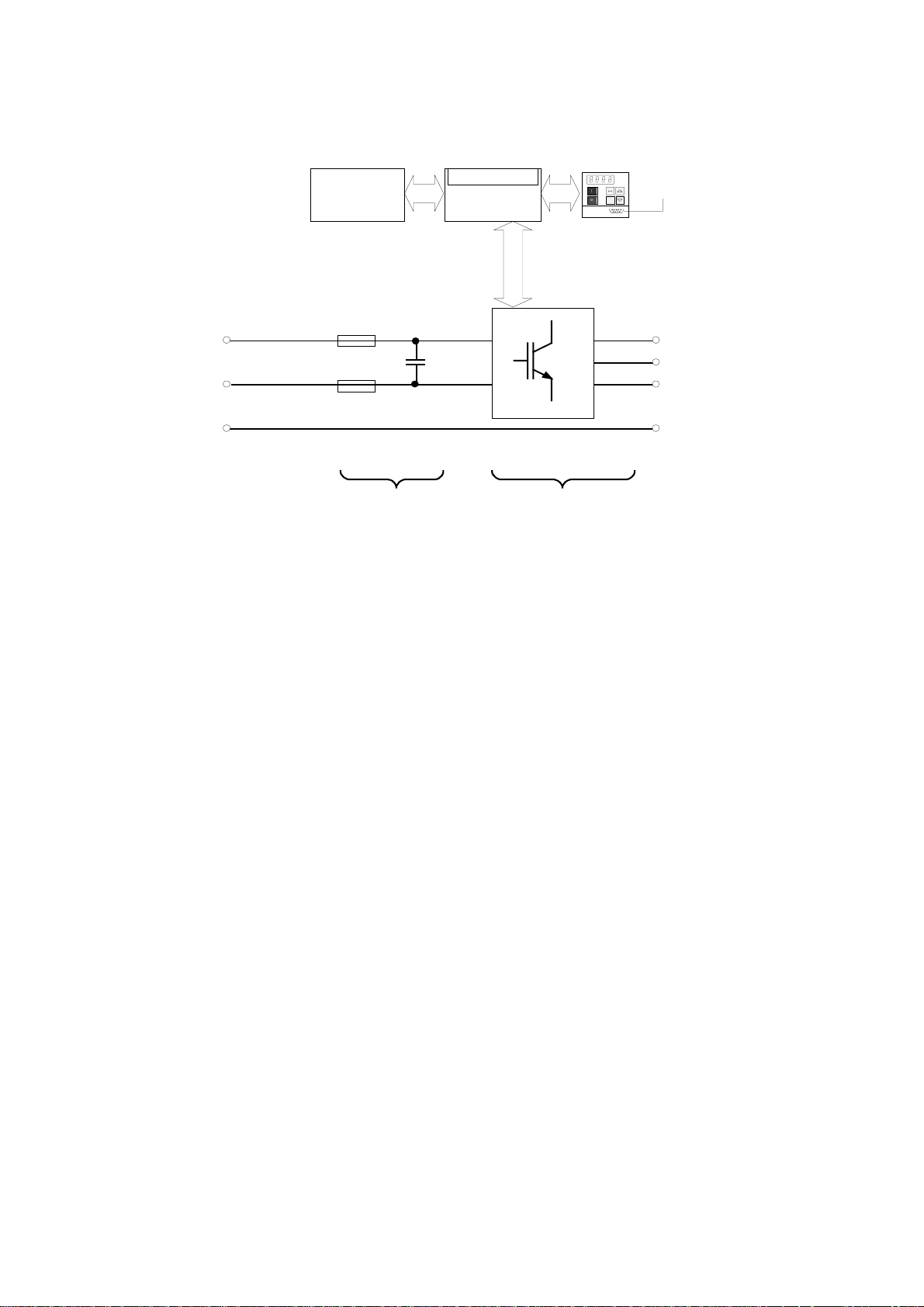
1.4 Block diagram
Option boards-
in the electronics box
C / L+
DC bus
connection
D / L -
PE1
Fusing and
DC link
Fig. 1.1 Block diagram, types of construction J and K
Terminal strip
CU
Inverter with
CU and PMU
Connector f or OP1
P
U2/T1
V2/T2
W2/T3
PE2
Motor
connection
Siemens AG 6SE7087-6BM70
SIMOVERT MASTER DRIVES Operating Instructions
1-3

Description 08.96
DC bus
connection
C / L+
D / L -
PE1
Option boards
in the electronics box
Master
Fusing and
DC link
Slave
Terminal strip
CU
Inverter with
CU and PMU
Connector for OP1
P
PE2
Motor
connection
U2/T1
V2/T2
W2/T3
PE1
Fusing and
Fig. 1.2 Block diagram, type of construction M
DC link
PE2
Inverter with
CU and PMU
1-4 Siemens AG 6SE7087-6BM70
SIMOVERT MASTER DRIVES Operating Instructions

12.96 Transport, Unpacking, Installation
2 Transport, Unpacking, Installation
2.1 Transport and unpacking
The units are packed in the manufacturing plant corresponding to that specified when ordered. A product packing
label is located on the outside of the packing.
Please observe the instructions on the packaging for transport, storage and professional handling.
For transportation with a fork-lift truck the converter is mounted on a wooden pallet.
Vibration and jolts must be avoided during transport, e.g. when setting the unit down.
The converter can be installed after it has been unpacked and checked to ensure that everything is complete
and that the converter is not damaged.
If the converter is damaged you must inform your shipping company immediately.
The packaging consists of a wooden floor sectionand a PE foil to protect the equipment from humidity. It
can be disposed of in accordance with local regulations.
Depending on the degree of protection and type of construction, the units may be mounted on a pallet either with
or without transport rails.
♦ Degree of prot. IP00 Pallet
• Type of construction J one unit
• Type of construction K one unit
• Type of construction M three units
− master drive converter, type of construction K
− reactor
− slave drive converter, type of construction K without electronics box
♦ Degree of prot. IP20 8MC cabinet on transport rails and pallet
• Type of construction J one 8MC cabinet
• Type of construction K one 8MC cabinet
• Type of construction M three 8MC cabinets combined to form a single unit
− master type of construction K
− reactor
− slave drive converter, type of construction K without electronics box
Chassis units are supplied, as standard, with degree of protection IP00.
2.2 Storage
The converters must be stored in clean dry rooms.Temperatures between − 25 °C (−13 °F) and + 70 °C (158 °F)
are permissible. Temperature fluctuations > 20 K per hour are not permissible.
WARNING
The equipment should not be stored for longer than one year. If it is stored for longer
periods of time, the converter DC link capacitors must be formed at start-up.
Capacitor forming is described in Part 2 of the Operating Instructions.
Siemens AG 6SE7087-6BM70
SIMOVERT MASTER DRIVES Operating Instructions
2-1
Transport, Unpacking, Installation 12.96
2.3 Mounting
The following are required for mounting:
M8 bolt(s)
♦
♦ Dimension drawings: Fig. 2.1 for type of construction J, Fig. 2.2 for type of construction K and
Fig. 2.5 for type of construction M.
♦ Only type of construction M: Engineering support
WARNING
Safe converter operation requires that the equipment is mounted and commissioned by
qualified personnel taking into account the warning information provided in this Instruction
Manual.
The general and domestic installation and safety regulations for work on electrical power
equipment (e.g. VDE) must be observed as well as the professional handling of tools and
the use of personnal protective equipment.
Death, severe bodily injury or significant material damage could result if these instructions
are not followed.
Chassis units do not provide any protection against direct contact. It is the users
responsibility to ensure and provide the correct protection against contact according to the
relevant accident prevention regulations VBG4, by appropriately designing the enclosure or
enclosures around the chassis unit.
Remove shipping brace (marked).
The three units, type of construction M with degree of protection IP00, must be assembled according to the
instructions specified in the engineering support documentation.
The control connections between the master and slave must then be established.
Procedure: The control cables must be carefully routed through the cable duct in the reactor chassis in the
♦
master cabinet.
Insert connectors -X238 / -X234 / -X32 / -X42.
•
Insert the fiber-optic cables U41 / U51 / U61 / U42 / U43 / U52 / U53 / U62 / U63 in the
•
master, at the IPI.
NOTE
Inserting the fiber-optic cables: Insert the fiber-optic cable up to its end stop (approx. 16 mm), tighten up
the union nut by hand.
CAUTION
Fiber-optic cables may not be bent through a sharp angle.
Bending radius for fiber-optic cables ≥ 30 mm.
The unit is mounted corresponding to the dimension drawings in Section 2.4.
2-2 Siemens AG 6SE7087-6BM70
SIMOVERT MASTER DRIVES Operating Instructions

12.96 Transport, Unpacking, Installation
Equipment rooms must be dry and dust-free. Ambient and cooling air must not contain any electrically conductive
gases, vapors and dusts which could diminish the functionality. Dust-laden air must be filtered.
WARNING
When mounting in cabinets, a clearance of above and below must be provided so that the
cooling air flow is not restricted (refer to dimension drawings, Section 2.4).
Dimension the cabinet cooling in line with the power loss! (+ Section „Technical data“)
The converter ambient climate in operating rooms may not exceed the values of code F according to DIN 40040.
For temperatures > 40 °C (104 °F) and installation altitudes > 1000 m, de-rating is required (+ Section
„Technical data“).
Siemens AG 6SE7087-6BM70
SIMOVERT MASTER DRIVES Operating Instructions
2-3
Transport, Unpacking, Installation 12.96
)
7
6SE70-IP0
0
2
2)Protectiveconductor4x300m
m
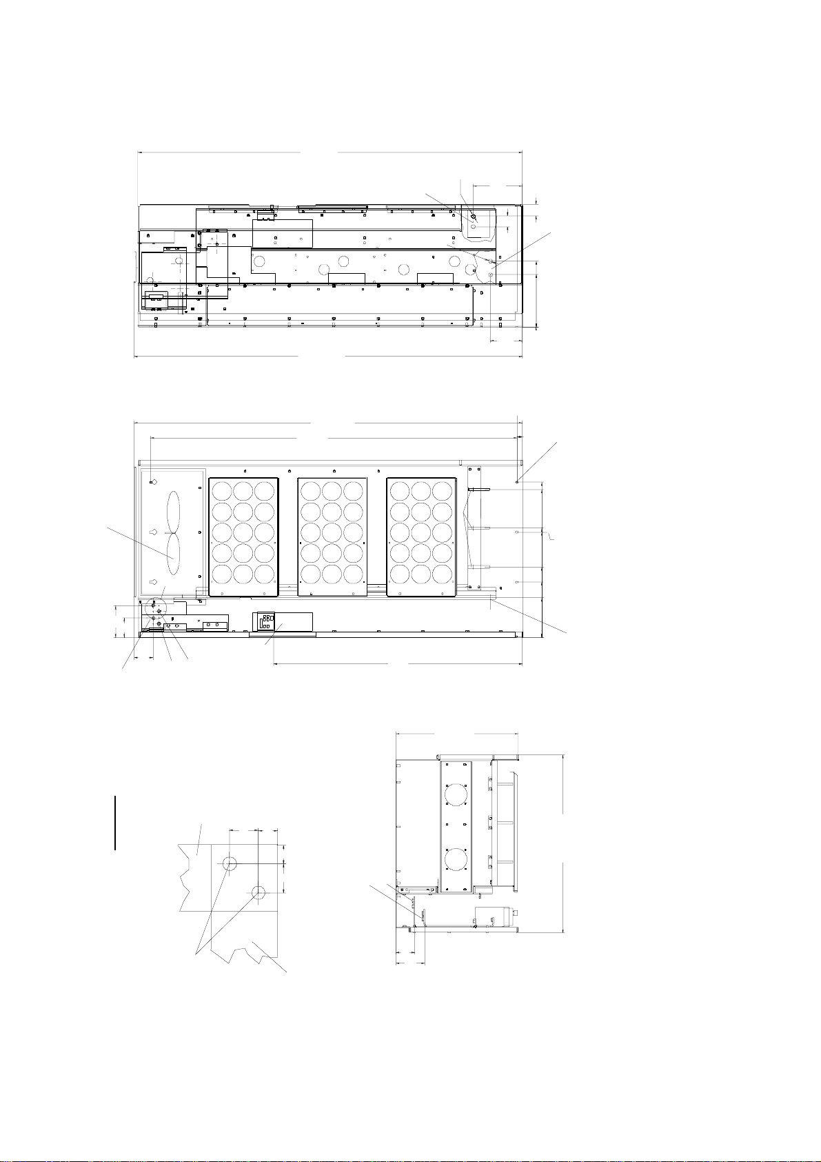
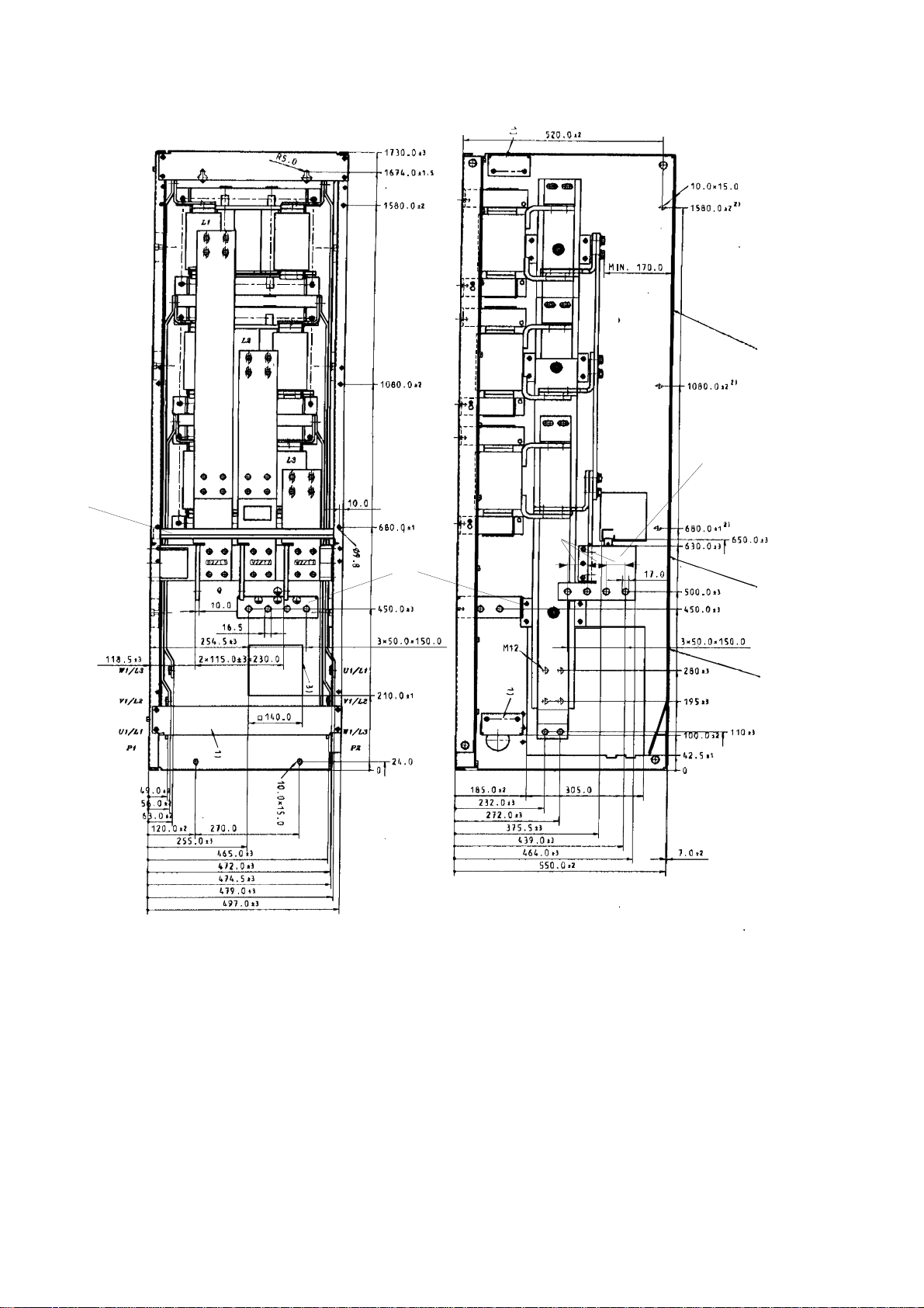
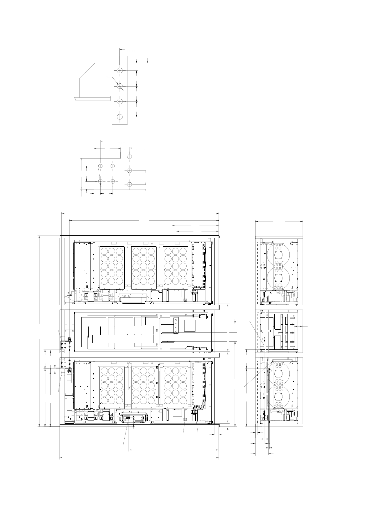
2.4 Dimension drawings
1
ø1
5
,
6
1
ø
1400 +5
222,5
45
50
2)
295
235
DC-AC chassis unit
0
145,5
Type of construction J
1400
+5
1345
1)
Fan assembly must be removed
to disassemble the unit
139
83
67
x
26
Electronics box
17
17
26
Detail X
DC positive
DC negative
to the DC busbar
ca. 710
550 +5
DC positive
DC negative
0
45
Elongated hole 9x12
708
+5
668,5
493,5
483
318,5
213
177
2)
0
2
Net weight, approx. 250 kg
With transport parts approx. 270 kg
1) - Conne ction for 4 x 300 mm
800
W
V
U
ø13,5 (M 12)
DC connection in accor dance with
DIN 43673 with 6 x 60 mm copper bar
to the rectifier/
regenerative
feedback unit
85
130
Fig. 2.1 Type of construction J
2-4 Siemens AG 6SE7087-6BM70
SIMOVERT MASTER DRIVES Operating Instructions
12.96 Transport, Unpacking, Installation
6SE70IP00
1730
1)
ø17
5
,
6
1
ø
1750 +5
1750 +5
1675
)
1
Fan assembly must be removed
to disassemble the unit
x
222,5
5
4
0
5
145,5
25
VW
U
2)
295
235
0
DC-AC chassis unit
Type of construction
Elongated hole 9x12
708
668,5
493,5
483
318,5
213
177
3
139
8
87
X
DC positive
DC negative
to the DC busbar
Detail X
2)
1
M
(
5
,
DC connection in accordance with
3
DIN 43673 with 6 x 60 mm copper bar
1
ø
Fig. 2.2 Type of construction K
)
2
0
104
.
ca
Electronics box
26
17
17
6
2
to the rectifier/
regenerative
feedback unit
DC positive
DC negative
85
+5
550
130
0
0
800 +5
2
2
1) - Connection for 4 x 300 mm
2) - Protective co nductor , 4 x 3 00 mm
Net w ei ght , app r ox . 25 0 kg
With transport parts approx. 540 kg
Siemens AG 6SE7087-6BM70
2-5
SIMOVERT MASTER DRIVES Operating Instructions
Transport, Unpacking, Installation 12.96
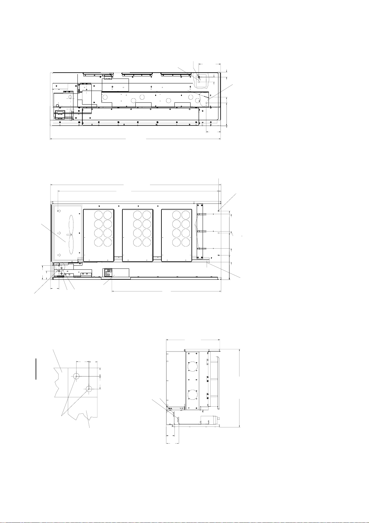
View without cover 10460/10470 View without side panel
Top cover: transparent
B)
C)
1) Painted transport rail
2) Only in the side panel left
3) Cut-out in the rear panel
50
A)
Divi ded cove rBottom cover: transparent
Cover including
bolt head
A) = PE conne ction (8 x 2 40 mm )
B) = Power connection output (8 x 240 mm )
C) = Cable duct for control cables from the Master to the Slave
Fig. 2.3 Reactor chassis, Type of construction M
2-6 Siemens AG 6SE7087-6BM70
SIMOVERT MASTER DRIVES Operating Instructions
12.96 Transport, Unpacking, Installation
)
(589
25
)
100
(
25
7
2
1
10 mm th i ck
50
50
50
U, V, W connecting lugs
(max. 8 x 240 mm )
(1975)
85
2
13
50
25
C, D connecting lugs
alternatively 4 x cable lugs
directly at the C D bus
(max. 4 x 240 mm )
(13 mm diameter hole or M12)
20
40
(1880)
10 mm thick
45
15
Weight:
IP00: ~ 1200 kg
IP20: ~ 1550 kg
SIMOVERT MASTER DRIVES
Inverter
Components, frame size: M (12)
(Master, slave, reac tor chassis ) m ounted
in a cabinet frame (8MC)
(730) 100
1975
1880
589
600
+5
539
+10
D (-)
2400
5
6
240
2
45
C (+)
730
700
Fig. 2.4 Type of construction M
F102
X9
W
PE
V
U
F101
D (-)
600
112
112
~100
240
1072
900
C (+)
730
115
X9
F101
89
F102
45
1132
X300
(RS 485
Interf ace)
2000
+5
28
10
121
10
168
Siemens AG 6SE7087-6BM70
2-7
SIMOVERT MASTER DRIVES Operating Instructions
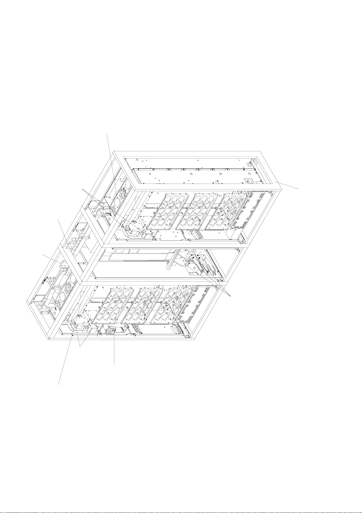
Transport, Unpacking, Installation 12.96
Cabinetfram
e
Fan a ss embly
Incoming fuse
F11, F12, F21, F22
D (-)
W
C (+)
V
U
SIMOVERT MASTER DRI VES
Inverter
Components, frame size: M (12)
(M ast er , s l ave, react or chassis) moun ted
in a cabinet frame ( 8MC)
Slave WR
Reactor
U, V, W
Ma ster WR
In coming fu ses
F11, F12, F21, F22
Elektronics box
with PMU
Fan a ssembly
Fig. 2.5 Type of construction M
2-8 Siemens AG 6SE7087-6BM70
SIMOVERT MASTER DRIVES Operating Instructions
08.96 Connecting-up
3 Connecting-up
WARNING
SIMOVERT MASTER DRIVES are operated at high voltages.
The equipment must be in a no-voltage condition (disconnected from the supply) before any
work is carried-out!
Only professionally trained, qualified personnel must work on or with the unit.
Death, severe bodily injury or significant material damage could occur if these warning
instructions are not observed.
Extreme caution should be taken when working-on the unit when it is open, as external
power supplies may be connected. The power terminals and control terminals can still be at
hazardous potentials even when the motor is stationary.
Hazardous voltages are still present in the unit up to 5 minutes after it has been powereddown due to the DC link capacitors. Thus, the appropriate delay time must be observed
before opening-up the unit.
Forming the DC link capacitors:
The storage time should not exceed one year. The converter DC link capacitors must be
formed at start-up if the unit has been stored for a longer period of time.
Forming is described in the Instruction Manual, Part 2.
When the DC link is supplied from a central unit, it must be ensured that the converter is
reliably isolated from the DC link voltage!
The user is responsible, that the motor, converter and any other associated devices or units
are installed and connected-up according to all of the recognized regulations in that
particular country as well as other regionally valid regulations. Cable dimensioning, fusing,
grounding, shutdown, isolation and overcurrent protection should be especially observed.
INFORMATION
♦ In the factory setting, the converter protects the motor from overload:
• P362 = 0 (self-ventilated motor)
• P364.2 = 100 (motor load limit in %)
No evaluation for P364.2 = 0.
Supply rating: The converter is suitable for connecting to supplies with a short-circuit rating (supply)
♦
100 × rated output (converter).
≤
Thermal motor protection: Motor temperature sensor (thermistor, type M135 or KTY84) can be connected
♦
at -X103:41-42.
Cabling/wiring:Connecting cables should be dimensioned according to the local regulations and according
♦
to Table 3.1. The insulation should be suitable for 75°C.
Siemens AG 6SE7087-6BM70
SIMOVERT MASTER DRIVES Operating Instructions
3-1
Connecting-up 08.96
3.1 Power connections
WARNING
♦ By interchanging the input terminals, the converter or the rectifier will be destroyed!
♦ The drive converter or rectifier unit could be destroyed if the input terminals are
interchanged!
♦ The coils of contacts and relays which are connected to the same supply as the
converter or are located in the vicinity of the converter, must be provided with
overvoltage limiters, e.g. RC elements.
The position of the connecting terminals can be seen in the dimension drawings (+
DC connection: C/L+ D/L
Motor connection: U2/T1 V2/T2 W2/T3
Protective conductor connection: PE1
The power connections should be established using cable lugs with screws according to Table 3.2.
For type of construction J, jumpers are inserted after the inverter connections, which can be replaced by fuses.
For drive converters, type of construction K, fuses are installed as standard.
−
PE2
Section 2.4).
NOTE
The 230 V fans must be externally supplied with 230 V AC via terminal strip X9.
NOTE
Depending on the motor insulation strength and the length of the motor feeder cable, it may be necessary to
install one of the following options between the motor and the converter:
Output reactor
♦
dv/dt-filter
♦
Information regarding selection and dimensioning is provided in Section „Options“.
3-2 Siemens AG 6SE7087-6BM70
SIMOVERT MASTER DRIVES Operating Instructions
08.96 Connecting-up
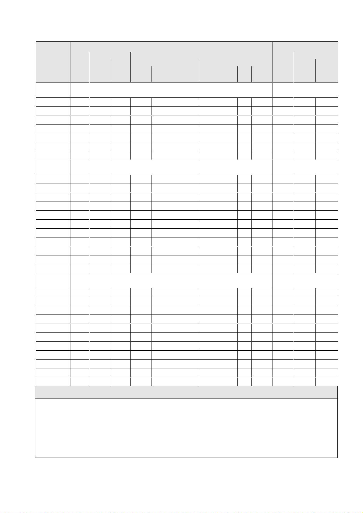
Supply side Motor side
Order Rated Cross-section Recommended fuse Rated Cross-section
No. DC North-America AC
Curr. VDE AWG Curr. VDE AWG
6SE70 (A) (mm2) MCM1)(A) Type Type (V) (A) (A) (mm2) MCM
Input voltage
DC 510 V to 620 V
Output voltage
3 AC 0 V to 620 V
35-1TJ20 607 4×300 4×800 2×450 2×3NE3233 2×170M6709 660 2×550 510 2×300 2×800
36-0TK20 702 4×300 4×800 2×560 2×3NE3335 2×170M6710 660 2×630 590 4×300 4×800
37-0TK20 821 4×300 4×800 2×560 2×3NE3335 2×170M6710 660 2×630 690 4×300 4×800
38-6TK20 1023 4×300 4×800 2×710 2×3NE3337-8 2×170M6711 660 2×700 860 4×300 4×800
41-1TK20 1309 6×300 6×800 2×800 2×3NE3338-8 1100 4×300 4×800
41-1TM20 1310 6×300 6×800 2×560 2×3NE3335 2×170M6710 660 2×650 1100 4×300 4×800
41-3TM20 1547 6×300 6×800 2×560 2×3NE3335 2×170M6710 660 2×650 1300 6×300 6×800
Input voltage
DC 675 V to 780 V
Output voltage
3 AC 0 V to 780 V
33-0UJ20 354 2×300 2×800 1×500 3NE3334-0B 170M5713 660 700 297 2×300 2×800
33-5UJ20 421 2×300 2×800 1×630 3NE3336 170M5713 660 700 354 2×300 2×800
34-5UK20 538 2×300 2×800 1×710 3NE3337-8 170M5714 660 900 452 2×300 2×800
35-7UK20 678 4×300 4×800 2×450 2×3NE3233 2×170M5712 660 2×630 570 2×300 2×800
36-5UK20 774 4×300 4×800 2×500 2×3NE3334-0B 2×170M5712 660 2×630 650 4×300 4×800
38-6UK20 1023 4×300 4×800 2×630 2×3NE3336 2×170M6712 660 2×800 860 4×300 4×800
41-0UM20 1178 6×300 6×800 1×710 3NE3337-8 170M5714 660 900 990 4×300 4×800
41-1UM20 1285 6×300 6×800 2×450 2×3NE3233 2×170M5712 660 2×630 1080 4×300 4×800
41-2UM20 1464 6×300 6×800 2×500 2×3NE3334-0B 2×170M5712 660 2×630 1230 6×800 6×800
41-4UM20 1666 6×300 6×800 2×630 2×3NE3336 2×170M6712 660 2×800 1400 6×800 6×800
41-6UM20 1880 8×300 8×800 2×630 2×3NE3336 2×170M6712 660 2×800 1580 6×800 6×800
Input voltage
DC 890 V to 930 V
Output voltage
3 AC 0 V to 930 V
33-0WJ20 354 2×300 2×800 1×500 3NE3334-0B 170M5713 660 700 297 2×300 2×800
33-5WJ20 421 2×300 2×800 1×630 3NE3336 170M5713 660 700 354 2×300 2×800
34-5WK20 538 2×300 2×800 1×710 3NE3337-8 170M5714 660 900 452 2×300 2×800
35-7WK20 678 4×300 4×800 2×450 2×3NE3233 2×170M5712 660 2×630 570 2×300 2×800
36-5WK20 774 4×300 4×800 2×500 2×3NE3334-0B 2×170M5712 660 2×630 650 4×300 4×800
38-6WK20 1023 4×300 4×800 2×630 2×3NE3336 2×170M6712 660 2×800 860 4×300 4×800
41-0WM20 1178 6×300 6×800 1×710 3NE3337-8 170M5714 660 900 990 4×300 4×800
41-1WM20 1285 6×300 6×800 2×450 2×3NE3233 2×170M5712 660 2×630 1080 4×300 4×800
41-2WM20 1464 6×300 6×800 2×500 2×3NE3334-0B 2×170M5712 660 2×630 1230 6×800 6×800
41-4WM20 1666 6×300 6×800 2×630 2×3NE3336 2×170M6712 660 2×800 1400 6×800 6×800
41-6WM20 1880 8×300 8×800 2×630 2×3NE3336 2×170M6712 660 2×800 1580 6×800 6×800
NOTES
♦ Current- and voltage data in this table are rated values
♦ The cables to the drive converter are protected using fuses with gL characteristics.
♦ The cross-sections are determined for three-core copper cables, routed horizontally in air at 30 °C (86°F)
ambient temperature (according to DIN VDE 0298 Part 2 / Group 5) and the recommended cable protection
according to DIN VDE 0100 Part 430.
2
♦ AWG (American Wire Gauge): American wire gauge for cross sections up to 120 mm
♦ MCM (Mille Circular Mil): American wire gauge for cross-sections above 120 mm
Table 3.1 Connection cross-sections and fusibles
Siemens AG 6SE7087-6BM70
SIMOVERT MASTER DRIVES Operating Instructions
;
2.
3-3
Connecting-up 08.96
Type of Order No. Max. cross-section Gland
construc.
(mm2) acc. to VDE MCM
J 6SE70_._.-._._J20 4×300 4×800 M16
K 6SE70_._.-._._K20 4×300 4×800 M16
M 6SE70_._.-._._M20 8×300 8×800 M16
Table 3.2 Maximum cross-section and gland
3.1.1 Protective conductor connection
The protective conductor should be connected-up on both the supply- and motor sides. It should be dimensioned
according to the power connections.
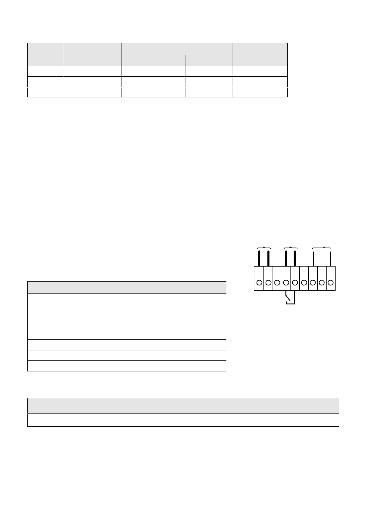
3.2 Auxiliary power supply/main contactor or bypass contactor
The auxiliary power supply and the main- or bypass contactor are connected through the 5-pin connector X9.
Connector X9 is supplied together with the connectors for the control terminal strip. Cables from 0.2 mm
2
2.5 mm
The auxiliary power supply is required if the drive converter is fed
through a main- and bypass contactor.
(AWG: 24 to 14) can be connected to X9.
E x t. 24 V
DC PS
Main contactor
control
The main- or monitoring contactor is controlled through floating contacts
-X9.4 and -X9.5 (software pre-setting).
More detailed information is provided in the Section „options“.
M
P
12345
6789
-X 9
Term. Function description
1 Types of construction J and K 24 V DC external ≥ 5 A (max.
8 A dependent on the options)
Type of construction M 24 V DC external ≥ 10 A (max.
16 A dependent on the options)
2 Reference potential to DC
3 Unassigned
4 Main contactor control
5 Main contactor control
Table 3.3 Connector assignment for -X9
Fig. 3.1 Connecting an external 24 V
power supply and main contact or
control
AC 230 V
1 kVA
2
to
230 V
fan
NOTES
The main contactor coil must be provided with overvoltage limiters, e.g. RC element.
3-4 Siemens AG 6SE7087-6BM70
SIMOVERT MASTER DRIVES Operating Instructions

08.96 Operator control
4 Operator control
The converter can be controlled via:
the PMU (Parameterization Unit)
♦
the control terminal strip on the CU (+ section “Control terminal strip“)
♦
the OP1 operator control panel (+ section “Options“)
♦
the RS485 and RS232 serial interface on PMU-X300
♦
Operator control using the PMU is described in this section.
Seven-segment displays
On key
Off key
P
Fig. 4.1 Parameterization unit
4.1 Operator control elements
Operator control elements Function
Converter switch on (standard).
For faults: Return to the fault display.
Command is effective when the key is released.
Converter shutdown depending on the parameterization of OFF 1, OFF 2 or
OFF 3 (P554 to P560).
Command becomes effective when the key is released.
Field reversal / reversing for the appropriate parameterization.
Command becomes effective when the key is released.
Reversing key
Raise key
Changeover key, operator control leve
Lower key
X300
P
Changeover from parameter number to parameter value. In conjunction with
other keys, additional functions (see Operating Instructions, Part 2).
Command becomes effective when the key is released.
Values (raise, lower) change as long as the keys are depressed.
,
P
+ resp.
Table 4.1 Function of the operator control elements on the PMU
Siemens AG 6SE7087-6BM70
SIMOVERT MASTER DRIVES Operating Instructions
P
+
Depress P and hold, then depress the second key. The command becomes
effective when the key is released (e.g. fast changeover).
4-1

Operator control 08.96
4.2 Displays
Parameter number Index Parameter value
Pos. actual value
e.g
Neg. actual value
e.g e.g.. e.g.
Visualization
parameters
Setting
parameters
Table 4.2 Displaying visualization- and setting parameters on the PMU
Display
Table 4.3 Status display on the PMU
Basic converter
Technology board
Basic converter
Technology board
Actual value
Parameter value
not possible
Alarm Fault
NOTE
The parameter description is provided in the Operating Instructions, Part 2.
− − −
4-2 Siemens AG 6SE7087-6BM70
SIMOVERT MASTER DRIVES Operating Instructions

12.96 Maintenance
5 Maintenance
WARNING
SIMOVERT MASTER DRIVES are operated at high voltages.
All work carried-out on or with the equipment must conform to all of the relevant national
electrical codes (VBG4 in Germany).
Maintenance and service work may only be executed by qualified personnel.
Only spare parts authorized by the manufacturer may be used.
The specified maintenance intervals and also the instructions for repair and replacement
must be adhered to.
The drive units have hazardous voltage levels up to 5 min after the converter has been
powered-down due to the DC link capacitors so that the unit must only be opened after an
appropriate delay time.
The power- and control terminals can still be at hazardous voltage levels even though the
motor is at a standstill.
If it is absolutely necessary that the drive converter must be worked on when powered-up:
never touch any live components.
♦
only use the appropriate measuring and test equipment and protective clothing.
♦
always stand on an ungrounded, isolated and ESD-compatible pad.
♦
If these warnings are not observed this can result in death, severe bodily injury or significant
material damage.
Always have your MASTER DRIVE converter Order No. and serial No. available when contacting the service
department. These numbers and other important data are located on the drive converter rating plate.
5.1 Maintenance requirements
The fans are designed for a service life of 35000 hours at an ambient temperature of TU = 40 °C. They must be
replaced before their service life expires so that the drive converter availability is guaranteed.
INSTRUCTIONS for type of construction M
Type of construction M consists of two chassis units (master, open-loop/closed-loop controlled and slave
♦
controlled), size K, a reactor chassis and the associated busbars
The slave unit has no PMU an no electronics box.
♦
♦ Service/maintenance is the same as chassis units, type of construction K. The differences are described.
♦ The busbar design and the design of the three components is described in the engineering support.
♦ The connection of the control cables between the slave and the master is described in Sections 2.1 and 2.3.
Siemens AG 6SE7087-6BM70
SIMOVERT MASTER DRIVES Operating Instructions
5-1

Maintenance 12.96
5.2 Replacing components
WARNING
The fan may only replaced by qualified personnel.
The drive converters are still at hazardous voltage levels up to 5 min. after the
unit has been powered-down as a result of the DC link capacitors.
If these warnings are not observed, death, severe bodily injury or considerable
material damage could occur.
5.2.1 Replacing the fan
The fan assembly consists of:
• the fan housing
• a fan type of construction J
• one or two fans, type of construction K
• the starting capacitors
The fans are mounted in the fan assembly in the upper section
of the chassis unit.
• Remove connector X20
• Release both mounting bolts (M8) of the fan assembly
• For type of construction K with
one fan, the air deflection plate below the fan must be disassembled
(2 × M8)
• Withdraw the fan assembly towards the front, and if required, tilt it gently downwards and place carefully on
a flat surface
CAUTION
The fan assembly can weigh up to 38 kg depending on the drive converter rating.
• Remove the cable ties and fan connections
• Remove the fan mounting panel from the fan assembly and remove the fan from the mounting panel
• Install the new fan assembly in the inverse sequence
• Before commissioning the drive check that the fan can run freely and check the airflow direction. The air
must be blown upwards out of the unit.
5.2.2 Replacing the fuses
The fuses are installed in a fuse holder. The fuse holder is
Fuse link
mounted on a DIN mounting rail at the bottom left in the chassis
unit. The fuse holder must be opened to replace fuses.
Fuse holder
closed
Fig. 5.1 Fuse holder
Fuse holder
open
5-2 Siemens AG 6SE7087-6BM70
SIMOVERT MASTER DRIVES Operating Instructions

12.96 Maintenance
5.2.3 Replacing the starting capacitor
The starting capacitor is mounted next to the fan connection.
The starting capacitor is mounted on the fan assembly.
• Remove the plug connections from the starting capacitor
• Unbolt the starting capacitor
• Install a new starting capacitor in the inverse sequence
5.2.4 Replacing the capacitor bank
The capacitor assembly consists of three boards. Each board has a capacitor mounting element and a DC link
bus connection.
• Remove the plug connections
• Release the mechanical retaining elements (three screws: two at the left, one at the right)
• Remove the capacitor by slightly raising them and withdrawing them from the drive converter towards the
front.
The capacitors weight up to 30 kg depending on the drive converter rating.
• Install a new capacitor bank in the inverse sequence.
5.2.5 Replacing SML and SMU
SML Snubber Module Lower
SMU Snubber Module Upper
• Remove the capacitors
• Release the mounting screws (4 ×
M8 (torque: 8 - 10 Nm), 1 × M4 (max. 1.8 Nm))
• Remove the SML / SMU
Install the new board in the reverse sequence.
CAUTION
Siemens AG 6SE7087-6BM70
SIMOVERT MASTER DRIVES Operating Instructions
5-3

Maintenance 12.96
n
5.2.6 Removing and installing the module busbars
♦ Removal
• remove the capacitors
• release the bolts holding the module busbars
Bolts M8 power connections
M6 mounting and distance pieces
M4 snubber circuitry
• remove the SMU / SML insulation
• lift out the module busbars
♦ Installation
NOTE
There must be a 4 mm clearance between the positive and negative busbars. Thus, when installing the
module busbars, a template must be used (refer to Fig. 5.2), e.g. a 4 mm-thick plastic piece.
• hold the module busbars and insulation in place SMU / SML (M6)
Te mplate 4 mm
• the template is inserted in the module busbars instead of the DC link
busbars
• insert the SML- and SMU board (tighten-up the module connections
(M8, torque: 8-10 Nm)
• tighten-up the M6 nut on the distance studs (6 Nm)
Module busbars
+ connection
Module
busbars
- connectio
• connect-up the snubber resistors (M4 bolts, torque: max. 1.8 Nm)
• tighten-up the power connections (M8 bolts, torque: 13 Nm)
• remove the template from the module busbars.
Fig. 5.2 Install the module busbars
4
5.2.6.1 Replacing the balancing resistor
The balancing resistor is located at the rear mounting plane on the heatsink between the inverter modules, i.e.
behind the capacitors and the module busbars.
♦ Remove the capacitors
♦ Type of construction J
• remove the module busbars
• remove IGD
♦ type of construction K
• release the mounting bolts and remove the
balancing resistor.
• release the mounting bolts and remove the
balancing resistor.
Installation in the reverse sequence.
♦ The balancing resistor is tightened-up with 1.8 Nm.
A uniform coating of heat conducting paste must be applied to the base plate.
Observe the correct contact assignment!
5-4 Siemens AG 6SE7087-6BM70
SIMOVERT MASTER DRIVES Operating Instructions

12.96 Maintenance
5.2.7 Replacing boards
WARNING
The boards may only be replaced by qualified personnel.
It is not permissible that the boards are withdrawn or inserted under voltage.
Death, severe bodily injury or significant materal damage might result if these
instructions are not observed.
CAUTION
Boards contain components which could be damaged by electrostatic discharge. The
human body must be discharged immediately before an electronics board is touched.
This can be simply done by touching a conductive, grounded object immediately beforehand
(e.g. bare metal cubicle components).
5.2.7.1 Replacing the IVI / IPI (type of construction M)
IVI Inverter-Value Interface
IPI Inverter-Parallel Interface (for type of construction M)
The IVI / IPI is bolted to the rear of the electronics box
♦ Remove the electronics module to the endstop
♦ Remove the ground connection at the electronics module
• Remove all boards from the electronics box
• Remove both mounting bolts from the electronics box (Fig. 5.4)
• Release the electronics box and remove towards the front.
• Release the cable ties
• Remove the ABO / ABI (Adaption Board)
• Release the fiber-optic cables
• Unbolt the IVI and remove
• Install the new IVI in the inverse sequence
• Unbolt the IVI / IPI and remove
• Install the new IVI / IPI in the inverse sequence
Siemens AG 6SE7087-6BM70
SIMOVERT MASTER DRIVES Operating Instructions
5-5

Maintenance 12.96
5.2.7.2 Replacing the VDU and VDU resistor
VDU Voltage-Dividing Unit
VDU and VDU resistor are only available for drive converters with higher supply voltages. The VDU mounting
bracket is part of the electronic module assembly.
♦ VDU
• Remove the plug connectors
• Release the mounting bolt
• Remove the VDU
Install the new VDU in the inverse sequence.
♦ VDU resistor
• Release the cable ties
• Remove the plug connections
• Unbolt the VDU resistor
Install the new VDU resistor in the inverse sequence
5.2.7.3 Replacing the PSU
PSU Power-Supply Unit (Power Supply)
♦ Remove the VDU and VDU resistor (if available)
♦ Remove the VDU mounting panel
♦ Release the plug connections on the PSU
♦ Release the bolts ( six Torx M4) on the PSU
♦ Remove the PSU
Install the new PSU in the inverse sequence
5.2.7.4 Replacing the IGD
IGD IGBT-Gate Drive
The IGD is located behind the module busbars and consists of one board for type of construction J
three boards for type of construction K
• Remove the capacitors
• Remove SML and SMU
• Remove the module busing
Type of construction J
♦
• Remove nine fiber-optic cables at the top of the
IGD
• Release the mounting bolts and remove the
Type of construction K
♦
• Remove the fiber-optic cables at the left of the
IGD (three per IGD)
• Remove the P15 cable
IGD.
• Release the mounting bolts
• Withdraw the IGD from the retaining bolts
towards the right and remove
• Insert a new IGD, and insert towards the left in
the groove of the mounting bolts under the
incoming busbars.
Install a new IGD in the reverse sequence.
5-6 Siemens AG 6SE7087-6BM70
SIMOVERT MASTER DRIVES Operating Instructions

12.96 Maintenance
5.2.8 Replacing the snubber resistor
♦ Remove the capacitors
♦ Remove the SML- and SMU modules
♦ Remove the module busbars
♦ Release the mounting bolts (2 ×
M5, torque: max. 1.8 Nm) and remove the snubber resistor
♦ A uniform coating of heat conducting paste must be applied to the resistor
Install the new snubber resistor in the inverse sequence.
5.2.8.1 Replacing the IGBT modules
• Replace as for IGD, but additionally
• Remove the mounting bolts of the defective IGBT modules and remove the
IGBT.
• Install the new IGBT module. Observe the following:
− Coat the module mounting surface with a
thin and uniform coating of
heat conducting paste.
− Tighten-up the IGBT module mounting bolts with 3 Nm, observe the
sequence (Fig. 5.3).
34
2
1
Tighten-up the IGBT modules
1. By hand (
sequence: 2 - 5 - 3 - 6 - 1 - 4
2. tighten-up with 3 Nm,
sequence: 2 - 5 - 3 - 6 - 1 - 4
Fig. 5.3 Tighten-up IGBT modules
CECE
0,5 Nm),
≈
5
6
Siemens AG 6SE7087-6BM70
SIMOVERT MASTER DRIVES Operating Instructions
5-7

Maintenance 12.96
n
5.2.8.2 Replacing boards in the electronics box
Loosen the board retaining screws above
♦
and below the handles for
inserting/withdrawing the boards
Carefully remove the board using these
♦
handles making sure that the board
doesn’t catch on anything
Carefully locate the new board on the
♦
guide rails and insert it completely into the
Slot 1 (CU)
Slot 3 (Options)
Slot 2 (Options)
electronics box
Tighten the retaining screws above and
♦
below the handles.
Fig. 5.4 Electronics box equipped wi th CU (slot 1)
5.2.8.3 Replacing the PMU
(Parameterization Unit)
Remove the ground cable at the side panel.
♦
Carefully depress the snap on the adapter section and
♦
remove the PMU with adapter section from the
electronics box.
♦ Withdraw connector X108 on the CU
♦ Carefully withdraw the PMU board out of the adapter
section towards the front using a screwdriver.
♦ Install the new PMU board in the invsere sequence.
and options (slot 2 (right) and 3 (mi ddl e))
PMU
E-Box
Fig. 5.5 PMU with adapter section on the E box
Adapter sectio
Snap
5-8 Siemens AG 6SE7087-6BM70
SIMOVERT MASTER DRIVES Operating Instructions

08.96 Options
6 Options
6.1 Options which can be integrated into the electronics box
One or two option boards, listed in Table 6.1, can be inserted in the electronics box using the LBA option (local
bus adapter).
Before installing option boards in the electronics box, the
LBA (local Bus Adapter) has to be inserted.
Install the LBA bus expansion:
♦ Remove the CU (lefthand slot in the electronics box)
using the handles after first removing the connecting
cable to the PMU and both retaining screws.
♦ Insert the LBA bus expansion in the electronics box
(position, refer to the diagram) so that it snaps into
place.
♦ Re-insert the CU into the lefthand slot, screw the
retaining screws on the handles tight, and insert the
connecting cable to the PMU.
♦ Insert the option board in slot 2 (right) or slot 3
(center) of the electronics box, and screw into place.
Each option board may only by inserted in the
electronics box. If only one option is used, it must
always be inserted at slot 2 (right).
Slots in the electronics box Boards
Left Slot 1 (CU) CU
Center Slot 3 (options) CB1 / SCB1 / SCB2 / (TSY, not for T300)
Right Slots 2 (options) CB1 / SCB1 / SCB2 / TSY / TB
Fig. 6.1 Installing the Local B us Adapter
NOTE
Only one of each option board type may inserted in the electronics box.
TB (technology boards, e.g. T300) must always be inserted at slot 2. When a TB board is used, a TSY board
my not be inserted.
If only one option board is used it must always be inserted at slot 2.
Table 6.1 Possible arrangements of boards in the electronics box
Siemens AG 6SE7087-6BM70
SIMOVERT MASTER DRIVES Operating Instructions
6-1

Options 08.96
The options are supplied with the option description.
Desig-
Description Order No.
nation
LBA Local bus adapter for the electronics box. This is
required for installing T300, CB1, TSY, SCB1 and SCB2
T300 Technology board for controlling technological
processes
Board
description
Board
description
TSY Synchronizing board Board
description
SCB1 Serial communications board with fiber-optic cable for
serial I/O system and peer-to-peer connection
SCB2 Serial communications board for peer-to-peer
connection and USS protocol via RS485
Use of the serial interface with USS protocol
Board
description
Board
description
Application
description
CB1 Communications board with interface for SINEC- L2-DP,
(Profibus)
Use of the PROFIBUS DP interface
Board
description
Application
description
Table 6.2 Option boards and bus adapter
6SE7090-0XX84-4HA0
6SE7087-6CX84-4HA0
6SE7090-0XX84-0AH0
6SE7087-6CX84-0AH0
6SE7090-0XX84-0BA0
6SE7087-6CX84-0BA0
6SE7090-0XX84-0BC0
6SE7087-6CX84-0BC0
6SE7090-0XX84-0BD0
6SE7087-6CX84-0BD0
6SE7087-6CX87-4KB0
6SE7090-0XX84-0AK0
6SE7087-6CX84-0AK0
6SE7087-6CX87-0AK0
If the converter is supplied through an external main
contactor, the option board in the electronics box must
be supplied from an external power supply, according
to Table 6.3.
These values are required in addition to the current
drawn by the basic converter (+ section “Technical
Data“).
Board Current drain (mA)
CB1 190
SCB1 50
SCB2 150
TSY w/out tacho 150
T300 w/out tacho 620
Standard tacho
Type: 1PX 8001-1
Table 6.3 Current drain of the option boards
I0 95
(190 at 6000 RPM)
6-2 Siemens AG 6SE7087-6BM70
SIMOVERT MASTER DRIVES Operating Instructions

08.96 Options
6.2 Interface boards
The boards, listed in the following table must be externally mounted and wired-up on the external system side.
Desig-
Description Order No.
nation
SCI1 Serial I/O board (only in conjunction with SCB1).
Analog and binary input and outputs for coupling to the
Board
description
SCB1 via fiber-optic cable
SCI2 Serial I/O board (only in conjunction with SCB1)
Binary inputs and outputs for coupling to the SCB1 via
Board
description
fiber-optic cable.
DTI Digital tachometer interface Board
description
ATI Analog tachometer interface Board
description
Table 6.4 Interface boards
6.3 Power supplies
Designation Description Order number
Option
6SE7090-0XX84-3EA0
6SE7087-6CX84-0BC0
6SE7090-0XX84-3EF0
6SE7087-6CX84-0BC0
6SE7090-0XX84-3DB0
6SE7087-6CX84-3DB0
6SE7090-0XX84-3DF0
6SE7087-6CX84-3DF0
Use with
Power supply, 0.3 A 115 V / 230 V AC - 24 V 0.3 A DC 6SX7010-0AC14 e.g.: DTI
Power supply 1 A 115 V / 230 V AC - 24 V 1 A DC 6SX7010-0AC15 e.g.: 1 x SCI
Power supply 5 A 115 V / 230 V AC - 24 V 5 A DC 6EP1333-1SL11 Basic conv
Power supply 8 A 115 V / 230 V AC - 24 V 8 A DC Basic conv. + options
Table 6.5 Recommended power supply
Siemens AG 6SE7087-6BM70
SIMOVERT MASTER DRIVES Operating Instructions
6-3

Options 08.96
6.4 Isolating amplifiers
Input Output Order number
Option
Power supply:
V = 24 V DC ±20 %
I = 90 mA
Input isolating amplifiers for analog inputs
10 V to +10 V
−
20 mA to +20 mA
−
10 V to +10 V 6SX7010-0AC00
−
10 V to +10 V 6SX7010-0AC02
−
4 mA to +20 mA 4 mA to +20 mA 6SX7010-0AC01
Output isolating amplifiers for analog outputs
10 V to +10 V
−
10 V to +10 V
−
10 V to +10 V 6SX7010-0AC00
−
20 mA to +20 mA 6SX7010-0AC03
−
(+) 5
Input Output
(-) 4
Fig. 6.2 Isolating amplifiers
6 (0 V) 1 (+24 V)
0 V to +10 V 4 mA to +20 mA 6SX7010-0AC04
Table 6.6 Overview of isolating amplifiers
6.5 Power section
Options Description/function
Braking unit For converting the regenerative energy into heat
Braking resistors Load resistor for the braking unit
Electrical DC link coupling Switching the DC-AC converter in and out under load
Mechanical DC link coupling Switching the DC-AC converter in and out in a no-voltage condition
Input rectifier Input rectifier for one or several DC-AC converters
Input rectifier with line-
commutated feedback
Supply rectifier for one or several DC-AC converters for motor or generator
operation
2 (+)
3 (-)
Table 6.7 Power section options
6-4 Siemens AG 6SE7087-6BM70
SIMOVERT MASTER DRIVES Operating Instructions

08.96 Options
2
6.5.1 Output reactor, dv/dt filter
When longer feeder cables are used between the converter and motor:
the converter has to cope with additional current peaks due to re-charging the cable capacitances
♦
the motor insulation is additionally stressed as a result of transient voltage spikes caused by reflection.
♦
NOTE
In order to prevent premature aging of the motor
insulation and thus early failures, the following limit
values may not be exceeded at the motor terminals:
the permissible voltage gradient dv/dt and
♦
the permissible peak voltage between phase
♦
conductors
Fig. 6.3 Permissible limit values for the motor ins ul at i on
)
V
LL
)
[V]
V
LL
1500
1460
1000
500
*) Standard 1LA8 motors;
1LA8 motors with improvedi ns ul ation are available
for Siemens 1LA2, 1LA5, 1LA6
and 1LA8*) motors
for motors in accordance with IEC 34-17:199
(DIN VDE 0530, Part1, Sheet2)
1
234
Depending on the application, the voltagerate-of-rise, voltage and current peaks can be reduced using the
following options: Output reactor, dv/dt filter.
Characteristics of the output reactors and dv/dt filters:
t [µs]
Output
dv/dt filter
reactor
Reduces the current peaks for long cables yes yes
Reduces the voltage gradient (rate of rise) dv/dt at the motor
slightly yes
terminals
Limits the amplitude of the transient voltage peaks at the motor
no yes
terminals to the following typical values
800 V at 3AC 400 V to 460 V
≤
1000 V at 3AC 500 V to 575 V
≤
1250 V at 3AC 660 V to 690 V
≤
Reduces the supplementary losses in the motor no no
Reduces motor noise (corresponding to direct online operation) no no
Table 6.8
Siemens AG 6SE7087-6BM70
SIMOVERT MASTER DRIVES Operating Instructions
6-5

Options 08.96
6.5.1.1 Output reactor
The output reactor is especially used to limit additional current spikes caused by the cable capacitances when
long cables are used, i.e. it
♦ reduces the charge current spikes for long cables
♦ reduces the voltage rate-of-change dv/dt at the motor terminals.
It does
not reduce the magnitude of the transient voltage spikes at the motor terminals.
In order that the reactor temperature rise remains within the specified limits, the pulse frequency f
converter, rated motor frequency f
and the maximum drive converter output frequency f
mot N
max
the specified limits:
V/f = constant V = constant
510 V
to 620 V DC
675 V
to 930 V DC
510 V
to 620 V DC
Standard reactor (iron) fP ≤ 3 kHz
V/f / Vector control f
V/f textile f
≤ 87 Hz f
mot N
mot N
= f
max
≤
mot N
≤ 200 Hz f
≤ 200 Hz f
max
120 Hz not possible not possible not possible
Ferrite reactor fP ≤ 6 kHz
V/f / Vector control f
V/f textile f
Table 6.9 Output reactor design
600
500
≤ 150 Hz f
mot N
mot N
= f
600 Hz not possible
≤
max
2 output reactorss
(not permissible for ferrite reactors)
max
≤ 300 Hz
of the drive
p
must lie within
675 V
to 930 V DC
≤ 300 Hz
max
400
300
Max. cable length / m
200
100
Fig. 6.4 Permissible cable lengths with and without output reac t ors
1 output reactor
without output reactor
1000100101
Drive converter outputs / kW
NOTE
The specified lengths are valid for unshielded cables; for shielded cables, these values must be reduced to 2/3.
If several motors are connected to a drive converter, the sum of the cables lengths of all the motor feeder
cables must be less than the permissible cable length.
6-6 Siemens AG 6SE7087-6BM70
SIMOVERT MASTER DRIVES Operating Instructions

08.96 Options
6.5.1.2 dv/dt filter
The dv/dt filter protects the motor insulation by limiting the voltage gradient and the transient peak voltage at the
motor winding to uncritical values in accordance with IEC 34-17:1992 (DIN VDE 0530, Part 1, Sheet 2):
♦ Voltage gradient (rate of rise) dv/dt ≤
500 V/µs
♦ Transient peak voltage at the motor terminals:
≤ 800 V for 380 V≤ UN ≤ 460 V (3 ph. AC)
Û
typ.
1000 V for 500 V≤ U
typ.
typ.
≤
1250 V for 660 V≤ U
≤
Û
Û
≤ 575 V (3 ph. AC)
N
≤ 690 V (3 ph. AC).
N
For long feeder cables, the dv/dt filter simultaneously reduces the current spikes, which additionally load the
drive converter due to the re-charging of the cable capacitances.
The dv/dt filter can be used for the following control versions
FC (Frequency Control) and
♦
VC (Vector Control)
♦
The dv/dt filter is suitable for use with
grounded supply networks (TN- and TT supply networks)
•
ungrounded supplies (IT supplies)
•
(exceptions: 6SE70_ _ - _ _ B _ _ -1FD0 and 6SE70 _ _ - _ _ C _ _ -1FD0 with version release A)
NOTE
The dv/dt filter is designed for a pulse frequency fp = 3 kHz and an output frequency fA ≤
In this case, when the drive converter is being set (P052 = 5), parameter P092 should be set to 2. Thus,
parameter P761 (pulse frequency) is automatically limited to values ≤ 3 kHz.
300 Hz.
400
300
200
100
Max. cable length / m
Fig. 6.5 Permissible cable lengths with dv/dt filter
dv/dt filter in series
with the output reactor
dv/dt filter
1000100101
Drive converter output / kW
NOTES
The specified cable lengths are valid for unshielded cables; for shielded cables, these values should be
reduced to 2/3.
If several motors are connected to a drive converter, the sum of the cable lengths of all of the motor feeder
cables must be less than the permissible cable length.
Siemens AG 6SE7087-6BM70
SIMOVERT MASTER DRIVES Operating Instructions
6-7

Options 08.96
6.5.1.3 Selection criteria for the output reactor or dv/dt filter
The following table indicates the selection criteria for the output reactor or dv/dt filter
Voltage range
510 V - 675 V (DC) 710 V - 780 V (DC) 890 V - 930 V (DC)
Motors, acc. to
IEC 34-17:1992
(DIN VDE 0530,
Part 1, Sheet 2)
Siemens motors
1LA2,
1LA5,
1LA6,
1)
1LA8
.
dv/dt filter required!
Cable lengths in accordance
with the Section „dv/dt filter“,
Fig. 6.5.
An output filter is not
required.
For longer motor cable
lengths, output reactors are
required in accordance with
dv/dt filter required!
Cable lengths in accordance
with the Section „dv/dt filter“,
Fig. 6.5.
dv/dt filter required!
Cable lengths in accordance
with the Section „dv/dt filter“,
Fig. 6.5.
dv/dt filter required!
Cable lengths in accordance
with the Section „dv/dt filter“,
Fig. 6.5.
dv/dt filter required!
Cable lengths in accordance
with the Section „dv/dt filter“,
Fig. 6.5.
Section „Output reactor“, Fig.
6.4.
Siemens motors
2)
1LA8
1)
2)
Table 6.10 Selection c ri t eri a for the following options: Out put reactor and dv/dt filt er between the converter and motor
.
Standard 1LA8 motors
1LA8 motors with a better insulation
An output filter is not
required.
For longer motor cable
lengths, output reactors are
required in accordance with
Section „Output reactor“,
Fig. 6.4.
An output filter is not
required.
For longer motor cable
lengths, output reactors are
required in accordance with
Section „Output reactor“,
Fig. 6.4.
An output filter is not
required.
For longer motor cable
lengths, output reactors are
required in accordance with
Section „Output reactor“,
Fig. 6.4.
6-8 Siemens AG 6SE7087-6BM70
SIMOVERT MASTER DRIVES Operating Instructions

08.96 Options
6.6 Bypass- and output contactor
6.6.1 Bypass contactor (electrical DC link
coupling)
Using the electrical DC link coupling, it is possible, for a
multi-motor group with common DC bus, to connect or
disconnect a converter with DC supply input to the DC
bus.
This option is used when an inverter section has to be
replaced.
Binary output -X9:4,5 is provided to control the contactor.
C/L+ D/L-
-K10
C/
-X1
L+
-X2
U2/T1V2/T2W2/
D/
L-
T3
DC24 V
12-X9
Auxiliary voltage
bypass contactor
Electrical DC
link coupling
-K10
-X9:4
-X9:5
6.6.1.1 Bypass contactor without I/R unit
Parameterization for operation with bypass contactor:
Parameter- Terminal
No. Name Value
P612, i001
P629, i001
Table 6.11 Parameterizat i on for the bypass contact or
ST. MC energized 0000 X9: 4,5
ST.BC energized 1001 X9: 4,5
(electrical DC link coupling)
M
3
Fig. 6.6 Connecting-up example for the bypass contactor
Siemens AG 6SE7087-6BM70
SIMOVERT MASTER DRIVES Operating Instructions
6-9

Options 08.96
6.6.1.2 Bypass contactor with I/R unit
NOTE
If individual inverters have to be isolated when the DC busbar is supplied through an input/regenerative
feedback unit, the the appropriate parameter sets of the infeed/regenerative feedback unit must be
simultaneously switched-over using the binary input. An optimization run for each required constellation must
be executed to determine the appropriate parameters. A maximum of four parameter sets can be selected.
If the DC busbar is to be fed from an infeed/regenerative feedback unit, the control parameter values must be
determined for this infeed/regenerative feedback unit.
Re-parameterization for the optimization run:
♦
Parameter- Terminal Information
No. Name Value
During commissioning, the following steps are required:
P629, i001
P612, i001
P600, i001
Table 6.12 Parameterizat i on for the optimization run
Execute the optimization run to determine the values for the closed-loop control parameters for the
♦
ST.BC energized 0000 X9: 4,5
ST.BC energized 1001 X9: 4,5
ST. ready to switch-on 1001 X9: 4,5 Bypass contactor closes
infeed/regenerative feedback unit (+ Instruction Manual, infeed/regenerative feedback unit).
Re-parameterize for operation with the bypass contactor:
♦
Parameter- Terminal Information
No. Name Value
P600, i001
P629, i001
ST.ready-to-switch-on 0000 X9: 4,5
ST.BC energiz. 1001 X9: 4,5
NOTE
In this case, the converter must be externally supplied with 24 V DC (connector -X9: 1,2)
Table 6.13 Parameterizat i on for the bypass contact or (el ectrical DC link coupling)
6-10 Siemens AG 6SE7087-6BM70
SIMOVERT MASTER DRIVES Operating Instructions

08.96 Options
6.6.1.3 Connecting and disconnecting individual converters to the DC bus
Sequence control
Switch the converter to the DC bus Isolate the converter from the DC bus
Close the fuse disconnect switch Output an off command
DC link is pre-charged through the pre-charging
Bypass contactor drops out
resistors
Enter an on command Open the fuse disconnect switch
Bypass contactor is closed Converter is electrically isolated from the DC bus
Wait until the DC link capacitors have completely
discharged
Table 6.14 Sequence control for connecting/disconnec ting individual converters t o the bus
6.6.2 Output contactor
It is not necessary that the converter is operated with output
-X1
C/
L+
D/
L-
contactor.
If the converter is operated with output contactor, binary output-
X9:4,5 is provided for contactor control (re-assignment).
The checkback signal can be connected to a binary input (e.g.
binary input 3).
U2/T1V2/T2W2/
-X2
T3
-K11
M
3
Fig. 6.7 Example for connecting-up a output
contactor
Sequence control, on command-operation (effect on the bypass-or output contactor)
Auxiliary voltage
output contactor
-K11
-X9:4
-X9:5
-X101:13
-X101:18
-K11
NOTES
For the special case, where a customer wishes to connect-up both an electrical DC link coupling as well as an
output contactor, then one of the two must be energized through a binary output. For higher ratings, an
additional auxiliary contactor must be provided due to the 230 V AC required (contactor coil).
Siemens AG 6SE7087-6BM70
SIMOVERT MASTER DRIVES Operating Instructions
6-11

Options 08.96
6.7 Operator control
Option Description
OP1 User-friendly operator control panel with plain text display
SIMOVIS Floppy disk with program for operator control via PC
Table 6.15 Operator control opti ons
Fault
Run
I
O
Jog
7 8
1 2
0
Fig. 6.8 OP1
P
9
6
54
3
+/- Reset
6-12 Siemens AG 6SE7087-6BM70
SIMOVERT MASTER DRIVES Operating Instructions

08.96 Spare Parts
7 Spare Parts
7.1 Converter 510 V to 620 V DC
Part code No. Designation Order number No . Used in
+A10 -U1 (-A100, -A101, -A110, -A111, -A200, -A201,
-A210, -A211, -A300, -A301, -A 310, -A311)
+A12 -U1 (-A100, -A101, -A110, -A111, -A200, -A201,
-A210, -A211, -A300, -A301, -A 310, -A311)
+A10 -U1 (-A108, -A109, -A208, -A209, -A308, -A309)
+A12 -U1 (-A108, -A109, -A208, -A209, -A308, -A309)
+A10 -U1 (-A118, -A119, -A218, -A219, -A318, -A319)
+A12 -U1 (-A118, -A119, -A218, -A219, -A318, -A319)
+A10 -U1 (-A19, -A29, -A39)
+A12 -U1 (-A19, -A29, -A39)
+A10 -U1 (-C110, -C120)
+A12 -U1 (-C110, -C120)
+A10 -U1 (-E1, -E2)
+A12 -U1 (-E1, -E2)
+A10 -U1 (-E1, -E2)
+A12 -U1 (-E1, -E2)
+A10 -U1 (-E1, -E2)
+A12 -U1 (-E1, -E2)
+A10 -U1 (-F101, -F102)
+A12 -U1 (-F101, -F102)
+A10 -U1 (-F101, -F102)
+A12 -U1 (-F101, -F102)
+A10 -U1 (-F41, -F42, -F43, -F44)
+A12 -U1 (-F41, -F42, -F43, -F44)
+A10 -U1 (-R100, -R200, -R300)
+A12 -U1 (-R100, -R200, -R300)
+A10 -U1 (-R108, -R109, -R118, -R119, -R208, -R209,
-R218, -R219, -R308, -R309, -R318, -R319)
+A12 -U1 (-R108, -R109, -R118, -R119, -R208, -R209,
-R218, -R219, -R308, -R309, -R318, -R319)
+A10 -U1 -G25
+A12 -U1 -G25
-G25 PSU2 power supply
-G25 PSU2 power supply
-A10 CU2 open- and closed-
-A100, -A101, -A110, -A111, -A 200, -A201, -A210, -A211,
-A300, -A301, -A310, -A311
-A100, -A101, -A110, -A111, -A 200, -A201, -A210, -A211,
-A300, -A301, -A310, -A311
IGBT transistor modul e 6SY7000-0AB70 24 6SE7041-1TM20
SMU3 inverter snubber
board
SML3 inverter snubber
board
IGD8 inverter gating
board
MKP capacitor for t he
fan
Radial fan 6SY7000-0AB68 4 6S E7041-1TM20
Nozzle for radial fan 6SY7000-0AB65 4 6SE7041-1TM20
Nozzle for radial fan 6SY7000-0AB65 4 6SE7041-3TM20
Fused load
disconnector
Fuse insert 6SY7000-0AC34 4 6SE7041-1TM20
Fuse insert 6SY7000-0AB75 8 6S E7041-1TM20
Balancing resistor 6SY7000-0AB08 6 6SE7041-1TM20
Snubber resistor 6SY7000-0AB18 24 6SE7041-1TM20
PSU2 power supply
board
board
board
loop control board (VC)
IGBT transistor modul e 6SY7000-0AB70 12 6SE7036-0TK20
IGBT transistor modul e 6SY7000-0AA82 12 6SE7038-6TK20
6SE7038-6EK84-1GF0 12 6SE7041-1TM20
6SE7038-6EK841GG0
6SE7037-0EK84-1JC0 6 6SE7041-1TM20
6SY7000-0AB64 4 6SE7041-1TM20
6SY7000-0AA26 4 6SE7041-1TM20
6SE7038-6GL84-1JA0 2 6SE7041-1TM20
6SE7038-6GL84-1JA0 1 6SE7035-1TJ20
6SE7038-6GL84-1JA1 1 6SE7041-1TK20
6SE7090-0XX84-0AF0 1 6SE7035-1TJ 20
6SE7041-3TM20
6SE7041-3TM20
12 6SE7041-1TM20
6SE7041-3TM20
6SE7041-3TM20
6SE7041-3TM20
6SE7041-3TM20
6SE7041-3TM20
6SE7041-3TM20
6SE7041-3TM20
6SE7041-3TM20
6SE7041-3TM20
6SE7036-0TK20
6SE7037-0TK20
6SE7038-6TK20
6SE7036-0TK20
6SE7037-0TK20
6SE7038-6TK20
6SE7041-1TK20
6SE7041-1TM20
6SE7041-3TM20
6SE7037-0TK20
Siemens AG 6SE7087-6BM70
SIMOVERT MASTER DRIVES Operating Instructions
7-1

Spare Parts 08.96
Part code No. Designation Order number No . Used in
-A100, -A110, -A200, -A210, -A 300, -A310 IGBT transistor modul e 6SY7000-0AB13 6 6S E 7035-1TJ20
-A100, -A101, -A110, -A111, -A 200, -A201, -A210, -A211,
-A300, -A301, -A310, -A311
-A108, -A109, -A208, -A209, -A 308, -A309 SMU3 inverter snubber
-A109, -A209, -A309 SMU3 inverter snubber
-A118, -A119, -A218, -A219, -A 318, -A319 SML3 inverter snubber
-A119, -A219, -A319 SML3 inverter snubber
-A19, -A29, -A39 IGD8 inverter gating
-A19, -A29, -A39 IGD8 inverter gating
-A20 IVI inverter interface
-A20 IVI inverter interface
-A22 IPI parallel switching
-A25 ABI normalization board 6SE7041-1TM84-1CF0 1 6SE7041-1TM20
-A25 ABI normalization board 6SE7041-3TM84-1CF0 1 6SE7041-3TM20
-A26 ABO normalization
-A26 ABO normalization
-A26 ABO normalization
-A26 ABO normalization
-A26 ABO normalization
-A29 IGD7 inverter gating
-A30 PMU operator
IGBT transistor modul e 6SY7000-0AB13 12 6SE7041-1TK20
board
board
board
board
board
board
board
board
board
board
board
board
board
board
board
control/parameterizing
unit
DC link capacitors,
complete with mounti ng
assembly
DC link capacitors,
complete with mounti ng
assembly
DC link capacitors,
complete with mounti ng
assembly
6SE7038-6EK84-1GF0 6 6SE7036-0TK20
6SE7038-6EK84-1GF0 3 6SE7035-1TJ20
6SE7038-6EK841GG0
6SE7038-6EK841GG0
6SE7037-0EK84-1JC0 3 6SE7036-0TK20
6SE7038-6EK84-1JC0 3 6SE7038-6TK20
6SE7038-6GL84-1BG0 1 6SE7035-1TJ20
6SE7038-6GL84-1BG2 1 6SE7041-1TK20
6SE7090-0XX84-1CE0 1 6SE7041-1TM20
6SE7035-1EJ84-1BH0 1 6SE7035-1TJ20
6SE7036-0TK84-1BH0 1 6SE7036-0TK20
6SE7037-0EK84-1BH0 1 6SE7037-0TK20
6SE7038-6EK84-1BH0 1 6SE7038-6TK20
6SE7041-1TK84-1BH0 1 6SE7041-1TK20
6SE7035-1EJ84-1JC0 1 6SE7035-1TJ20
6SE7090-0XX84-2FA0 1 6SE 7035-1TJ20
6SY7000-0AC31 3 6SE7035-1TJ20
6SY7000-0AC25 3 6SE7036-0TK20
6SY7000-0AC26 3 6SE7038-6TK20
6SE7037-0TK20
6SE7038-6TK20
6SE7041-1TK20
6 6SE7036-0TK20
6SE7037-0TK20
6SE7038-6TK20
6SE7041-1TK20
3 6SE7035-1TJ20
6SE7037-0TK20
6SE7041-1TK20
6SE7036-0TK20
6SE7037-0TK20
6SE7038-6TK20
6SE7041-3TM20
6SE7036-0TK20
6SE7037-0TK20
6SE7038-6TK20
6SE7041-1TK20
6SE7041-1TM20
6SE7041-3TM20
6SE7037-0TK20
7-2 Siemens AG 6SE7087-6BM70
SIMOVERT MASTER DRIVES Operating Instructions

08.96 Spare Parts
Part code No. Designation Order number No . Used in
DC link capacitors,
complete with mounti ng
assembly
DC link capacitors,
complete with mounti ng
assembly
-C110 MKP capacitor for t he
-C110, -C120 MKP capacit or for the
-C110, -C120 MKP capacit or for the
-E1 Nozzle for the radial fan 6SY7000-0AB65 1 6SE7035-1TJ20
-E1 Radial fan 6SY7000-0AB68 1 6S E7035-1TJ20
-E1, -E2 Nozzle for the radial fan 6SY7000-0AB65 2 6SE7036-0TK20
-E1, -E2 Nozzle for the radial fan 6SY7000-0AC41 2 6SE7041-1TK 20
-E1, -E2 Radial fan 6SY7000-0AB68 2 6S E7036-0TK20
-E1, -E2 Radial fan 6SY7000-0AC40 2 6SE7041-1TK20
-F101, -F102 Fused load
-F101, -F102 Fuse insert 6SY7000-0AC34 2 6SE7035-1TJ20
-F101, -F102 Fuse insert 6SY7000-0AC42 2 6SE7041-1TK20
-F41, -F42, -F43, -F44 Fus e i ns ert 6SY7000-0AB75 4 6SE7036-0TK20
-F41, -F42, -F43, -F44 Fus e i ns ert 6SY7000-0AB88 4 6SE7038-6TK20
-F41, -F42, -F43, -F44 Fuse insert 6SY7000-0AC64 4 6SE7041-1TK20
-R100, -R200, -R300 Balancing resistor 6SY7000-0AB08 3 6SE7036-0TK20
-R100, -R200, -R300 Balancing resistor 6SY9705 3 6SE7035-1TJ20
-R100, -R200, -R300 Balancing resistor 6SY7000-0AA77 3 6SE7038-6TK20
-R100, -R200, -R300 Balancing resistor 6SY7000-0AA76 3 6SE7041-1TK20
-R108, -R109, -R118, -R119, -R208, -R209, -R218, R219, -R308, -R309, -R318, -R319
-R109, -R119, -R209, -R219, -R309, -R319 Snubber resistor 6SY7000-0AB18 6 6SE7035-1TJ20
OPTION L31: +A10 -U1 (-F41, -F42, -F43, -F44),+A12
-U1 (-F41, -F42, -F43, -F44)
OPTION L31: -F41, -F42, -F43, -F44 Fuse i nsert 6SY7000-0AC20 4 6SE7038-6TK20
OPTION L31: -F41, -F42, -F43, -F44 Fuse i nsert 6SY7000-0AC05 4 6SE7035-1TJ20
OPTION L31: -F41, -F42, -F43, -F44 Fuse i nsert 6SY7000-0AC03 4 6SE7036-0TK20
fan
fan
fan
disconnector
Snubber resistor 6SY7000-0AB18 12 6SE7036-0TK20
Fuse insert 6SY7000-0AC03 8 6SE7041-1TM20
6SY7000-0AC25 6 6SE7041-1TM20
6SE7041-3TM20
6SY7000-0AC65 3 6SE7041-1TK20
6SY7000-0AB64 1 6SE7035-1TJ20
6SY7000-0AB64 2 6SE7036-0TK20
6SE7037-0TK20
6SE7038-6TK20
6SY7000-0AC38 2 6SE7041-1TK20
6SE7037-0TK20
6SE7038-6TK20
6SE7037-0TK20
6SE7038-6TK20
6SY7000-0AA26 2 6SE7035-1TJ20
6SE7036-0TK20
6SE7037-0TK20
6SE7038-6TK20
6SE7041-1TK20
6SE7036-0TK20
6SE7037-0TK20
6SE7038-6TK20
6SE7037-0TK20
6SE7035-1TJ20
6SE7037-0TK20
6SE7037-0TK20
6SE7038-6TK20
6SE7041-1TK20
6SE7041-3TM20
6SE7037-0TK20
Siemens AG 6SE7087-6BM70
SIMOVERT MASTER DRIVES Operating Instructions
7-3

Spare Parts 08.96
Part code No. Designation Order number No . Used in
ACCESSORIES Connector set,
SIMOVERT VC
ACCESSORIES Connector set,
SIMOVERT VC
6SY7000-0AC13 1 6SE7035-1TJ20
6SE7036-0TK20
6SE7037-0TK20
6SE7038-6TK20
6SE7041-1TM20
6SE7041-3TM20
6SY7000-0AC50 1 6SE7041-1TK20
Table 7.1 Spare parts
7.2 Converter 675 V to 780 V DC
Part code No. Designation Order No. No. Used i n
+A10 -U1 (-A100, -A101, -A 110, -A111, -A200, -A201,
-A210, -A211, -A300, -A301, -A 310, -A311)
+A12 -U1 (-A100, -A101, -A110, -A111, -A200, -A201,
-A210, -A211, -A300, -A301, -A 310, -A311)
+A10 -U1 (-A100, -A101, -A 110, -A111, -A200, -A201,
-A210, -A211, -A300, -A301, -A 310, -A311)
+A12 -U1 (-A100, -A101, -A 110, -A111, -A200, -A201, -
A210, -A211, -A300, -A301, -A 310, -A311)
+A10 -U1 (-A100, -A101, -A 110, -A111, -A200, -A201,
-A210, -A211, -A300, -A301, -A 310, -A311)
+A12 -U1 (-A100, -A101, -A 110, -A111, -A200, -A201,
-A210, -A211, -A300, -A301, -A 310, -A311)
+A10 -U1 (-A118, -A119, -A 218, -A219, -A318, -A319),
+A12 -U1 (-A118, -A119, -A 218, -A219, -A318, -A319)
+A10 -U1 (-A19, -A29, -A 39),
+A12 -U1 (-A19, -A29, -A 39)
IGBT transistor modul e 6SY7000-0AB71 24 6SE7041-0UM20
IGBT transistor modul e 6SY7000-0AC36 24 6SE7041-2UM20
IGBT transistor modul e 6SY7000-0AC37 24 6SE7041-4UM20
SML3 inverter snubber
board
IGD8 inverter gating
board
6SE7038-6GK841GG0
6SE7035-7GK84-1JC0 6 6SE7041-0UM20
6SE7041-1UM20
6SE7041-6UM20
12 6SE7041-0UM20
6SE7041-1UM20
6SE7041-2UM20
6SE7041-4UM20
6SE7041-6UM20
6SE7041-1UM20
+A10 -U1 (-A19, -A29, -A 39),
+A12 -U1 (-A19, -A29, -A 39)
+A10 -U1 (-A19, -A29, -A 39),
+A12 -U1 (-A19, -A29, -A 39)
+A10 -U1 (-C110, -C120),
+A12 -U1 (-C110, -C120)
+A10 -U1 (-C110, -C120),
+A12 -U1 (-C110, -C120)
+A10 -U1 (-C110, -C120),
+A12 -U1 (-C110, -C120)
+A10 -U1 (-E1, -E2),
+A12 -U1 (-E1, -E2)
+A10 -U1 (-E1, -E2),
+A12 -U1 (-E1, -E2)
+A10 -U1 (-E1, -E2),
+A12 -U1 (-E1, -E2)
IGD8 inverter gating
board
IGD8 inverter gating
board
MKP capacitor for t he
fan
MKP capacitor for t he
fan
MKP capacitor for t he
fan
Nozzle for radial fan 6SY7000-0AB65 4 6SE7041-0UM20
Radial fan 6SY7000-0AB68 4 6S E7041-0UM20
Nozzle for radial fan 6SY7000-0AB65 4 6SE7041-1UM20
6SE7038-6GK84-1JC0 6 6SE7041-2UM20
6SE7041-6UM20
6SE7036-5GK84-1JC0 6 6SE7041-4UM20
6SY7000-0AB64 4 6SE7041-0UM20
6SE7041-1UM20
6SY7000-0AC35 4 6SE7041-2UM20
6SY7000-0AC38 4 6SE7041-4UM20
6SE7041-6UM20
6SE7038-6UK20
6SE7041-1UM20
6SE7041-2UM20
7-4 Siemens AG 6SE7087-6BM70
SIMOVERT MASTER DRIVES Operating Instructions

08.96 Spare Parts
Part code No. Designation Order No. No. Used i n
+A10 -U1 (-E1, -E2),
+A12 -U1 (-E1, -E2)
+A10 -U1 (-F101, -F102),
+A12 -U1 (-F101, -F102)
+A10 -U1 (-F101, -F102),
+A12 -U1 (-F101, -F102)
Nozzle for radial fan 6SY7000-0AB65 4 6SE7041-2UM20
Fused load
disconnector
Fuse insert 6SY7000-0AC34 4 6SE7041-0UM20
6SY7000-0AA26 4 6SE7041-0UM20
6SE7041-1UM20
6SE7041-2UM20
6SE7041-4UM20
6SE7041-6UM20
6SE7041-1UM20
6SE7041-2UM20
+A10 -U1 (-F101, -F102),
+A12 -U1 (-F101, -F102)
+A10 -U1 (-F41, -F42, -F43, -F44),
+A12 -U1 (-F41, -F42, -F43, -F44)
+A10 -U1 (-F41, -F42, -F43, -F44),
+A12 -U1 (-F41, -F42, -F43, -F44)
+A10 -U1 (-F41, -F42, -F43, -F44),
+A12 -U1 (-F41, -F42, -F43, -F44)
+A10 -U1 (-R100, -R200, -R300),
+A12 -U1 (-R100, -R200, -R300)
+A10 -U1 (-R100, -R200, -R300),
+A12 -U1 (-R100, -R200, -R300)
+A10 -U1 (-R108, -R109, -R118, -R119, -R208, -R209,
-R218, -R219, -R308, -R309, -R318, -R319)
+A12 -u1 (-r108, -r109, -r118, -r119, -r208, -r209, -r218,
-r219, -r308, -r309, -r318, -r319)
+A10 -U1 -A28,
+A12 -U1 -A28
+A10 -U1 -G25,
+A12 -U1 -G25
G25 PSU2 power supply
+A10 -U1 -R28,
+A12 -U1 -R28
Fuse insert 6SY7000-0AC42 4 6SE7041-4UM20
Fuse insert 6SY7000-0AB77 8 6S E7041-0UM20
Fuse insert 6SY7000-0AB87 8 6S E7041-2UM20
Fuse insert 6SY7000-0AB74 8 6S E7041-4UM20
Balancing resistor 6SY7000-0AA77 6 6SE7041-0UM20
Balancing resistor 6SY7000-0AA76 6 6SE7041-4UM20
Snubber resistor 6SY7000-0AB18 24 6SE7041-0UM20
VDU voltage distribution
board
PSU2 power supply
board
board
VDU resistor 6SY7000-0AC33 2 6SE7041-0UM2 0
6SE7041-6UM20
6SE7041-1UM20
6SE7041-6UM20
6SE7041-1UM20
6SE7041-2UM20
6SE7041-6UM20
6SE7041-1UM20
6SE7041-2UM20
6SE7041-4UM20
6SE7041-6UM20
6SE7038-6GL84-1JB0 2 6SE 7041-0UM 20
6SE7041-1UM20
6SE7041-2UM20
6SE7041-4UM20
6SE7041-6UM20
6SE7038-6GL84-1JA0 2 6SE7041-0UM20
6SE7041-1UM20
6SE7041-2UM20
6SE7041-4UM20
6SE7041-6UM20
6SE7038-6GL84-1JA0 1 6SE7033-0UJ20
6SE7033-5UJ20
6SE7034-5UK20
6SE7035-7UK20
6SE7036-5UK20
6SE7038-6UK20
6SE7041-1UM20
6SE7041-2UM20
6SE7041-4UM20
6SE7041-6UM20
Siemens AG 6SE7087-6BM70
SIMOVERT MASTER DRIVES Operating Instructions
7-5

Spare Parts 08.96
Part code No. Designation Order No. No. Used i n
-A10 CU2 open- and closed-
-A100, -A101, -A110, -A111, -A 200, -A201, -A210, -A211,
-A300, -A301, -A310, -A311
-A100, -A101, -A110, -A111, -A 200, -A201, -A210, -A211,
-A300, -A301, -A310, -A311
-A100, -A101, -A110, -A111, -A 200, -A201, -A210, -A211,
-A300, -A301, -A310, -A311
-A100, -A101, -A110, -A111, -A 200, -A201, -A210, -A211,
-A300, -A301, -A310, -A311
-A100, -A110, -A200, -A210, -A 300, -A310 IGBT transistor modul e 6SY7000-0AC36 6 6SE7033-0UJ20
-A100, -A110, -A200, -A210, -A 300, -A310 IGBT transistor modul e 6SY7000-0AB14 6 6S E 7033-5UJ20
-A108, -A109, -A208, -A209, -A 308, -A309 SMU3 inverter snubber
-A109, -A209, -A309 SMU3 inverter snubber
-A118, -A119, -A218, -A219, -A 318, -A319 SML3 inverter snubber
-A118, -A119, -A218, -A219, -A 318, -A319 SML3 inverter snubber
-A119, -A219, -A319 SML3 inverter snubber
-A19, -A29, -A39 IGD8 inverter gating
-A19, -A29, -A39 IGD8 inverter gating
-A19, -A29, -A39 IGD8 inverter gating
-A19, -A29, -A39 IGD8 inverter gating
-A20 IVI inverter interface
-A22 IPI parallel switching
-A25 ABI normalization board 6SE7041-0UM84-1CF0 1 6SE7041-0UM20
-A25 ABI normalization board 6SE7041-1UM84-1CF0 1 6SE7041-1UM20
-A25 ABI normalization board 6SE7041-2UM84-1CF0 1 6SE7041-2UM20
-A25 ABI normalization board 6SE7041-4UM84-1CF0 1 6SE7041-4UM20
loop control board (VC)
IGBT transistor modul e 6SY7000-0AB12 12 6SE7034-5UK20
IGBT transistor modul e 6SY7000-0AB71 12 6SE7035-7UK20
IGBT transistor modul e 6SY7000-0AC36 12 6SE7036-5UK20
IGBT transistor modul e 6SY7000-0AC37 12 6SE7038-6UK20
board
board
board
board
board
board
board
board
board
board
board
6SE7090-0XX84-0AF0 1 6SE 7033-0UJ20
6SE7038-6GK84-1GF0 6 6S E7034-5UK20
6SE7038-6GK84-1GF0 3 6S E7033-0UJ20
6SE7038-6EK841GG0
6SE7038-6GK841GG0
6SE7038-6GK841GG0
6SE7034-5GK84-1JC0 3 6SE7034-5UK20
6SE7035-7GK84-1JC0 3 6SE7035-7UK20
6SE7038-6GK84-1JC0 3 6SE7036-5UK20
6SE7036-5GK84-1JC0 3 6SE7038-6UK20
6SE7038-6GL84-1BG0 1 6SE7033-0UJ20
6SE7090-0XX84-1CE0 1 6SE7041-0UM20
6SE7033-5UJ20
6SE7034-5UK20
6SE7035-7UK20
6SE7036-5UK20
6SE7038-6UK20
6SE7041-0UM20
6SE7041-1UM20
6SE7041-2UM20
6SE7041-4UM20
6SE7041-6UM20
6SE7035-7UK20
6SE7036-5UK20
6SE7038-6UK20
6SE7033-5UJ20
6
6 6SE7034-5UK20
6SE7035-7UK20
6SE7036-5UK20
6SE7038-6UK20
3 6SE7033-0UJ20
6SE7033-5UJ20
6SE7033-5UJ20
6SE7034-5UK20
6SE7035-7UK20
6SE7036-5UK20
6SE7038-6UK20
6SE7041-1UM20
6SE7041-2UM20
6SE7041-4UM20
6SE7041-6UM20
7-6 Siemens AG 6SE7087-6BM70
SIMOVERT MASTER DRIVES Operating Instructions

08.96 Spare Parts
Part code No. Designation Order No. No. Used i n
-A25 ABI normalization board 6SE7041-6UM84-1CF0 1 6SE7041-6UM20
-A26 ABO normalization
board
-A26 ABO normalization
board
-A26 ABO normalization
board
-A26 ABO normalization
board
-A26 ABO normalization
board
-A26 ABO normalization
board
-A26 ABO normalization
board
-A28 VDU voltage divider
board
-A29 IGD7 inverter gating
board
-A30 PMU operator control
parameterizing unit
DC link capacitors
complete with mounti ng
assembly
DC link capacitors
complete with mounti ng
assembly
DC link capacitors
complete with mounti ng
assembly
DC link capacitors
complete with mounti ng
assembly
DC link capacitors
complete with mounti ng
assembly
DC link capacitors
complete with mounti ng
assembly
-C110 MKP capacitor for t he
fan
6SE7033-0UJ84-1BH0 1 6SE7033-0UJ20
6SE7033-5UJ84-1BH0 1 6SE7033-5UJ20
6SE7034-5UK84-1BH0 1 6SE7034-5UK20
6SE7035-7UK84-1BH0 1 6SE7035-7UK20
6SE7036-5UK84-1BH0 1 6SE7036-5UK20
6SE7038-6EK84-1BH0 1 6SE7038-6UK20
6SE7038-6UK84-1BH0 1 6SE7038-6UK20
6SE7038-6GL84-1JB0 1 6SE 7033-0UJ20
6SE7033-5UJ20
6SE7034-5UK20
6SE7035-7UK20
6SE7036-5UK20
6SE7038-6UK20
6SE7033-5GJ84-1JC0 1 6SE7033-0UJ20
6SE7033-5UJ20
6SE7090-0XX84-2FA0 1 6SE 7033-0UJ20
6SE7033-5UJ20
6SE7034-5UK20
6SE7035-7UK20
6SE7036-5UK20
6SE7038-6UK20
6SE7041-0UM20
6SE7041-1UM20
6SE7041-2UM20
6SE7041-4UM20
6SE7041-6UM20
6SY7000-0AC27 3 6SE7034-5UK20
6SY7000-0AC31 3 6SE7033-0UJ20
6SE7033-5UJ20
6SY7000-0AC28 3 6SE7035-7UK20
6SE7036-5UK20
6SY7000-0AC30 3 6SE7038-6UK20
6SY7000-0AC28 6 6SE7041-0UM20
6SE7041-1UM20
6SE7041-2UM20
6SY7000-0AC30 6 6SE7041-4UM20
6SE7041-6UM20
6SY7000-0AB64 1 6SE7033-0UJ20
6SE7033-5UJ20
-C110, -C120 MKP capacit or for the
fan
Siemens AG 6SE7087-6BM70
SIMOVERT MASTER DRIVES Operating Instructions
6SY7000-0AB64 2 6SE7034-5UK20
6SE7035-7UK20
7-7

Spare Parts 08.96
Part code No. Designation Order No. No. Used i n
-C110, -C120 MKP capacit or for the
fan
-E1 Nozzle for the radial fan 6SY7000-0AB65 1 6SE7033-0UJ20
6SY7000-0AC35 2 6SE7036-5UK20
6SE7033-5UJ20
-E1 Radial fan 6SY7000-0AB68 1 6S E7033-0UJ20
-E1 Radial fan 6SY7000-0AC40 1 6SE7038-6UK20
-E1 Nozzle for the radial fan 6SY7000-0AC41 1 6SE7038-6UK 20
-E1, -E2 Nozzle for the radial fan 6SY7000-0AB65 2 6SE7034-5UK20
-E1, -E2 Radial fan 6SY7000-0AB68 2 6S E7034-5UK20
-E1, -E2 Nozzle for the radial fan 6SY7000-0AC41 2 6SE7041-4UM 20
-F101, -F102 Fused load
disconnector
-F101, -F102 Fuse insert 6SY7000-0AC34 2 6SE7033-0UJ20
6SY7000-0AA26 2 6SE7033-0UJ20
6SE7033-5UJ20
6SE7041-4UM20
6SE7041-6UM20
6SE7035-7UK20
6SE7036-5UK20
6SE7035-7UK20
6SE7036-5UK20
6SE7041-6UM20
6SE7033-5UJ20
6SE7034-5UK20
6SE7035-7UK20
6SE7036-5UK20
6SE7038-6UK20
6SE7033-5UJ20
6SE7034-5UK20
6SE7035-7UK20
6SE7036-5UK20
-F101, -F102 Fuse insert 6SY7000-0AC42 2 6SE7038-6UK20
-F41, -F42 Fuse insert 6SY7000-0AB87 2 6S E7033-0UJ20
-F41, -F42 Fuse insert 6SY7000-0AB74 2 6S E7033-5UJ20
-F41, -F42 Fuse insert 6SY7000-0AB88 2 6S E7034-5UK20
-F41, -F42, -F43, -F44 Fuse insert 6SY7000-0AB77 4 6SE 7035-7UK20
-F41, -F42, -F43, -F44 Fuse insert 6SY7000-0AB87 4 6SE 7036-5UK20
-F41, -F42, -F43, -F44 Fuse insert 6SY7000-0AB74 4 6SE 7038-6UK20
-R100, -R200, -R300 Balancing resistor 6SY9705 3 6SE7033-0UJ20
-R100, -R200, -R300 Balancing resistor 6SY7000-0AB08 3 6SE7034-5UK20
-R100, -R200, -R300 Balancing resistor 6SY7000-0AA77 3 6SE7035-7UK20
-R100, -R200, -R300 Balancing resistor 6SY7000-0AA76 3 6SE7038-6UK20
-R108, -R109, -R118, -R119, -R208, -R209, -R218, -
R219, -R308, -R309, -R318, -R319
-R109, -R119, -R209, -R219, -R309, -R319 Snubber resistor 6SY7000-0AB18 6 6SE7033-0UJ20
Snubber resistor 6SY7000-0AB18 12 6SE7034-5UK20
6SE7033-5UJ20
6SE7036-5UK20
6SE7035-7UK20
6SE7036-5UK20
6SE7038-6UK20
6SE7033-5UJ20
7-8 Siemens AG 6SE7087-6BM70
SIMOVERT MASTER DRIVES Operating Instructions

08.96 Spare Parts
Part code No. Designation Order No. No. Used i n
-R28 VDU res i stor 6SY7000-0AC33 1 6SE7033-0UJ20
OPTION L31: +A10 -U1 (-F41, -F42, -F43, -F44),
+A12 -U1 (-F41, -F42, -F43, -F44)
OPTION L31: +A10 -U1 (-F41, -F42, -F43, -F44),
+A12 -U1 (-F41, -F42, -F43, -F44)
OPTION L31: -F41, -F42 Fuse insert 6SY7000-0AC17 2 6SE7033-0UJ20
OPTION L31: -F41, -F42, -F43, -F44 Fus e insert 6SY7000-0AC16 4 6SE7035-7UK20
OPTION L31: -F41, -F42, -F43, -F44 Fus e insert 6SY7000-0AC20 4 6SE7038-6UK20
ACCESSORIES Connector set,
Fuse insert 6SY7000-0AC16 8 6SE7041-0UM20
Fuse insert 6SY7000-0AC20 8 6SE7041-4UM20
6SY7000-0AC13 1 6SE7033-0UJ20
SIMOVERT VC
6SE7033-5UJ20
6SE7034-5UK20
6SE7035-7UK20
6SE7036-5UK20
6SE7038-6UK20
6SE7041-1UM20
6SE7041-2UM20
6SE7041-6UM20
6SE7033-5UJ20
6SE7034-5UK20
6SE7036-5UK20
6SE7033-5UJ20
6SE7034-5UK20
6SE7035-7UK20
6SE7036-5UK20
6SE7038-6UK20
6SE7041-0UM20
6SE7041-1UM20
6SE7041-2UM20
6SE7041-4UM20
6SE7041-6UM20
7.3 Converter 890 V to 930 V DC
Part code No. Designation Order No. No. Used i n
+A10 -U1 (-A100, -A101, -A 110, -A111, -A200, -A201,
-A210, -A211, -A300, -A301, -A 310, -A311)
+A12 -U1 (-A100, -A101, -A 110, -A111, -A200, -A201,
-A210, -A211, -A300, -A301, -A 310, -A311)
+A10 -U1 (-A100, -A101, -A 110, -A111, -A200, -A201, -
A210, -A211, -A300, -A301, -A 310, -A311)
+A12 -U1 (-A100, -A101, -A 110, -A111, -A200, -A201,
-A210, -A211, -A300, -A301, -A 310, -A311)
+A10 -U1 (-A100, -A101, -A 110, -A111, -A200, -A201,
-A210, -A211, -A300, -A301, -A 310, -A311)
+A12 -U1 (-A100, -A101, -A 110, -A111, -A200, -A201, -
A210, -A211, -A300, -A301, -A 310, -A311)
+A10 -U1 (-A108, -A109, -A 208, -A209, -A308, -A309),
+A12 -U1 (-A108, -A109, -A 208, -A209, -A308, -A309)
+A10 -U1 (-A118, -A119, -A 218, -A219, -A318, -A319),
+A12 -U1 (-A118, -A119, -A 218, -A219, -A318, -A319)
+A10 -U1 (-A19, -A29, -A 39),
+A12 -U1 (-A19, -A29, -A 39)
+A10 -U1 (-A19, -A29, -A 39),
+A12 -U1 (-A19, -A29, -A 39)
IGBT transistor modul e 6SY7000-0AB71 24 6SE7041-0WM20
IGBT transistor modul e 6SY7000-0AC36 24 6SE7041-2WM20
IGBT transistor modul e 6SY7000-0AC37 24 6SE7041-4WM20
SMU3 inverter snubber
board
SML3 inverter snubber
board
IGD8 inverter gating
board
IGD8 inverter gating
board
6SE7038-6GK84-1GF0 12 6SE7041-6WM20
6SE7038-6GK841GG0
6SE7035-7GK84-1JC0 6 6SE7041-0WM20
6SE7038-6GK84-1JC0 6 6SE7041-2WM20
6SE7041-1WM20
6SE7041-6WM20
12 6SE7041-0WM20
6SE7041-1WM20
6SE7041-2WM20
6SE7041-4WM20
6SE7041-6WM20
6SE7041-1WM20
6SE7041-6WM20
Siemens AG 6SE7087-6BM70
SIMOVERT MASTER DRIVES Operating Instructions
7-9

Spare Parts 08.96
Part code No. Designation Order No. No. Used i n
+A10 -U1 (-A19, -A29, -A 39),
+A12 -U1 (-A19, -A29, -A 39)
+A10 -U1 (-C110, -C120),
+A12 -U1 (-C110, -C120)
+A10 -U1 (-C110, -C120),
+A12 -U1 (-C110, -C120)
+A10 -U1 (-C110, -C120),
+A12 -U1 (-C110, -C120)
+A10 -U1 (-E1, -E2),
+A12 -U1 (-E1, -E2)
+A10 -U1 (-E1, -E2),
+A12 -U1 (-E1, -E2)
+A10 -U1 (-E1, -E2),
+A12 -U1 (-E1, -E2)
+A10 -U1 (-E1, -E2),
+A12 -U1 (-E1, -E2)
+A10 -U1 (-F101, -F102),
+A12 -U1 (-F101, -F102)
+A10 -U1 (-F101, -F102),
+A12 -U1 (-F101, -F102)
+A10 -U1 (-F101, -F102),
+A12 -U1 (-F101, -F102)
+A10 -U1 (-F41, -F42, -F43, -F44),
+A12 -U1 (-F41, -F42, -F43, -F44)
+A10 -U1 (-F41, -F42, -F43, -F44),
+A12 -U1 (-F41, -F42, -F43, -F44)
+A10 -U1 (-F41, -F42, -F43, -F44),
+A12 -U1 (-F41, -F42, -F43, -F44)
+A10 -U1 (-R100, -R200, -R300),
+A12 -U1 (-R100, -R200, -R300)
+A10 -U1 (-R100, -R200, -R300),
+A12 -U1 (-R100, -R200, -R300)
+A10 -U1 -R108, -R109, -R118, -R119, -R208, -R209, -
R218, -R219, -R308, -R309, -R318, -R319)
+A12 -U1 (-R108, -R109, -R118, -R119, -R208, -R209, -
R218, -R219, -R308, -R309, -R318, -R319)
+A10 -U1 -A28,
+A12 -U1 -A28
+A10 -U1 -G25,
+A12 -U1 -G25
IGD8 inverter gating
board
MKP capacitor for t he
fan
MKP capacitor for t he
fan
MKP capacitor for t he
fan
Radial fan 6SY7000-0AB68 4 6S E7041-0WM20
Nozzle for the radial fan 6SY7000-0AB65 4 6SE7041-0WM20
Nozzle for the radial fan 6SY7000-0AB65 4 6SE7041-1WM20
Nozzle for the radial fan 6SY7000-0AB65 4 6SE7041-2WM20
Fused load
disconnector
Fuse insert 6SY7000-0AC34 4 6SE7041-0WM20
Fuse insert 6SY7000-0AC42 4 6SE7041-4WM20
Fuse insert 6SY7000-0AB77 8 6S E7041-0WM20
Fuse insert 6SY7000-0AB87 8 6S E7041-2WM20
Fuse insert 6SY7000-0AB74 8 6S E7041-4WM20
Balancing resistor 6SY7000-0AA77 6 6SE7041-0WM20
Balancing resistor 6SY7000-0AA76 6 6SE7041-4WM20
Snubber resistor 6SY7000-0AB18 24 6SE7041-0WM20
VDU resistor 6SE7038-6GL84-1JB0 2 6SE 7041-0WM 20
PSU2 power supply
board
6SE7036-5GK84-1JC0 6 6SE7041-4WM20
6SY7000-0AB64 4 6SE7041-0WM20
6SE7041-1WM20
6SY7000-0AC35 4 6SE7041-2WM20
6SY7000-0AC38 4 6SE7041-4WM20
6SE7041-6WM20
6SE7038-6WK20
6SE7041-1WM20
6SE7041-2WM20
6SY7000-0AA26 4 6SE7041-0WM20
6SE7041-1WM20
6SE7041-2WM20
6SE7041-4WM20
6SE7041-6WM20
6SE7041-1WM20
6SE7041-2WM20
6SE7041-6WM20
6SE7041-1WM20
6SE7041-6WM20
6SE7041-1WM20
6SE7041-2WM20
6SE7041-6WM20
6SE7041-1WM20
6SE7041-2WM20
6SE7041-4WM20
6SE7041-6WM20
6SE7041-1WM20
6SE7041-2WM20
6SE7041-4WM20
6SE7041-6WM20
6SE7038-6GL84-1JA0 2 6SE7041-0WM20
6SE7041-1WM20
6SE7041-2WM20
6SE7041-4WM20
6SE7041-6WM20
7-10 Siemens AG 6SE7087-6BM70
SIMOVERT MASTER DRIVES Operating Instructions

08.96 Spare Parts
Part code No. Designation Order No. No. Used i n
-G25 PSU2 power supply
+A10 -U1 -R28,
+A12 -U1 -R28
-A10 CU2 open- and closed-
-A100, -A101, -A110, -A111, -A 200, -A201, -A210, -A211,
-A300, -A301, -A310, -A311
-A100, -A101, -A110, -A111, -A 200, -A201, -A210, -A211,
-A300, -A301, -A310, -A311
-A100, -A101, -A110, -A111, -A 200, -A201, -A210, -A211,
-A300, -A301, -A310, -A311
-A100, -A101, -A110, -A111, -A 200, -A201, -A210, -A211,
-A300, -A301, -A310, -A311
-A100, -A110, -A200, -A210, -A 300, -A310 IGBT transistor modul e 6SY7000-0AC36 6 6SE7033-0WJ20
-A100, -A110, -A200, -A210, -A 300, -A310 IGBT transistor modul e
-A108, -A109, -A208, -A209, -A 308, -A309 SMU3 inverter snubber
-A109, -A209, -A309 SMU3 inverter snubber
-A118, -A119, -A218, -A219, -A 318, -A319 SML3 inverter snubber
-A119, -A219, -A319 SML3 inverter snubber
-A19, -A29, -A39 IGD8 inverter gating
-A19, -A29, -A39 IGD8 inverter gating
-A19, -A29, -A39 IGD8 inverter gating
-A19, -A29, -A39 IGD8 inverter gating
-A20 IVI inverter interface
board
VDU resistor 6SY7000-0AC33 2 6SE7041-0WM20
loop control board(VC)
IGBT transistor modul e 6SY7000-0AB12 12 6SE7034-5WK20
IGBT transistor modul e 6SY7000-0AB71 12 6SE7035-7WK20
IGBT transistor modul e 6SY7000-0AC36 12 6SE7036-5WK20
IGBT transistor modul e 6SY7000-0AC37 12 6SE7038-6WK20
fz1200r16kf1, 1200a,
1600v
board
board
board
board
board
board
board
board
board
6SE7038-6GL84-1JA0 1 6SE7033-0WJ20
6SE7090-0XX84-0AF0 1 6SE 7033-0WJ20
6SY7000-0AB14 6 6SE7033-5WJ20
6SE7038-6GK84-1GF0 6 6S E7034-5WK20
6SE7038-6GK84-1GF0 3 6S E7033-0WJ20
6SE7038-6GK841GG0
6SE7038-6GK841GG0
6SE7034-5GK84-1JC0 3 6SE7034-5WK20
6SE7035-7GK84-1JC0 3 6SE7035-7WK20
6SE7038-6GK84-1JC0 3 6SE7036-5WK20
6SE7036-5GK84-1JC0 3 6SE7038-6WK20
6SE7038-6GL84-1BG0 1 6SE7033-0WJ20
6SE7033-5WJ20
6SE7034-5WK20
6SE7035-7WK20
6SE7036-5WK20
6SE7038-6WK20
6SE7041-1WM20
6SE7041-2WM20
6SE7041-4WM20
6SE7041-6WM20
6SE7033-5WJ20
6SE7034-5WK20
6SE7035-7WK20
6SE7036-5WK20
6SE7038-6WK20
6SE7041-0WM20
6SE7041-1WM20
6SE7041-2WM20
6SE7041-4WM20
6SE7041-6WM20
6SE7035-7WK20
6SE7036-5WK20
6SE7038-6WK20
6SE7033-5WJ20
6 6SE7034-5WK20
6SE7035-7WK20
6SE7036-5WK20
6SE7038-6WK20
3 6SE7033-0WJ20
6SE7033-5WJ20
6SE7033-5WJ20
6SE7034-5WK20
6SE7035-7WK20
6SE7036-5WK20
6SE7038-6WK20
Siemens AG 6SE7087-6BM70
SIMOVERT MASTER DRIVES Operating Instructions
7-11

Spare Parts 08.96
Part code No. Designation Order No. No. Used i n
-A22 IPI parallel switching
board
-A25 ABI normalization board 6SE7041-0UM84-1CF0 1 6SE7041-0WM20
-A25 ABI normalization board 6SE7041-1WM84-
-A25 ABI normalization board 6SE7041-2WM84-
-A25 ABI normalization board 6SE7041-4WM84-
-A25 ABI normalization board 6SE7041-6WM84-
-A26 ABO normalization
board 297a
-A26 ABO normalization
board
-A26 ABO normalization
board
-A26 ABO normalization
board
-A26 ABO normalization
board
-A26 ABO normalization
board
-A28 VDU voltage divider
board
-A29 IGD7 inverter gating
board
-A30 PNU operator control
parameterizing unit
DC link capacitors wi th
complete mounting
assembly
DC link capacitors wi th
complete mounting
assembly
DC link capacitors wi th
complete mounting
assembly
DC link capacitors wi th
complete mounting
assembly
6SE7090-0XX84-1CE0 1 6SE7041-0WM20
1CF0
1CF0
1CF0
1CF0
6SE7033-0WJ84-1BH0 1 6SE7033-0WJ20
6SE7033-5WJ84-1BH0 1 6SE7033-5WJ20
6SE7034-5WK841BH0
6SE7035-7WK841BH0
6SE7036-5WK841BH0
6SE7038-6UK84-1BH0 1 6SE7038-6WK20
6SE7038-6GL84-1JB0 1 6SE 7033-0WJ20
6SE7033-5GJ84-1JC0 1 6SE7033-0WJ20
6SE7090-0XX84-2FA0 1 6SE 7033-0WJ20
6SY7000-0AC27 3 6SE7034-5WK20
6SY7000-0AC31 3 6SE7033-0WJ20
6SY7000-0AC28 3 6SE7035-7WK20
6SY7000-0AC30 3 6SE7038-6WK20
6SE7041-1WM20
6SE7041-2WM20
6SE7041-4WM20
6SE7041-6WM20
1 6SE7041-1WM20
1 6SE7041-2WM20
1 6SE7041-4WM20
1 6SE7041-6WM20
1 6SE7034-5WK20
1 6SE7035-7WK20
1 6SE7036-5WK20
6SE7033-5WJ20
6SE7034-5WK20
6SE7035-7WK20
6SE7036-5WK20
6SE7038-6WK20
6SE7033-5WJ20
6SE7033-5WJ20
6SE7034-5WK20
6SE7035-7WK20
6SE7036-5WK20
6SE7038-6WK20
6SE7041-0WM20
6SE7041-1WM20
6SE7041-2WM20
6SE7041-4WM20
6SE7041-6WM20
6SE7033-5WJ20
6SE7036-5WK20
7-12 Siemens AG 6SE7087-6BM70
SIMOVERT MASTER DRIVES Operating Instructions

08.96 Spare Parts
Part code No. Designation Order No. No. Used i n
DC link capacitors wi th
complete mounting
assembly
DC link capacitors wi th
complete mounting
assembly
-C110 MKP capacitor for t he
fan
-C110, -C120 MKP capacit or for the
fan
-C110, -C120 MKP capacit or for the
fan
-E1 Nozzle for the radial fan 6SY7000-0AB65 1 6SE7033-0WJ20
-E1 Radial fan 6SY7000-0AB68 1 6S E7033-0WJ20
-E1 Radial fan 6SY7000-0AC40 1 6SE7038-6WK20
-E1 Nozzle for the radial fan 6SY7000-0AC41 1 6SE7038-6WK 20
-E1, -E2 Nozzle for the radial fan 6SY7000-0AB65 2 6SE7034-5WK20
6SY7000-0AC28 6 6SE7041-0WM20
6SE7041-1WM20
6SE7041-2WM20
6SY7000-0AC30 6 6SE7041-4WM20
6SE7041-6WM20
6SY7000-0AB64 1 6SE7033-0WJ20
6SE7033-5WJ20
6SY7000-0AB64 2 6SE7034-5WK20
6SE7035-7WK20
6SY7000-0AC35 2 6SE7036-5WK20
6SE7033-5WJ20
6SE7033-5WJ20
6SE7041-4WM20
6SE7041-6WM20
6SE7035-7WK20
6SE7036-5WK20
-E1, -E2 Radial fan 6SY7000-0AB68 2 6S E7034-5WK20
-E1, -E2 Nozzle for the radial fan 6SY7000-0AC41 2 6SE7041-4WM 20
-F101, -F102 Fused load
disconnector
-F101, -F102 Fuse insert 6SY7000-0AC34 2 6SE7033-0WJ20
-F101, -F102 Fuse insert 6SY7000-0AC42 2 6SE7038-6WK20
-F41, -F42 Fuse insert 6SY7000-0AB87 2 6S E7033-0WJ20
-F41, -F42 Fuse insert 6SY7000-0AB74 2 6S E7033-5WJ20
-F41, -F42 Fuse insert 6SY7000-0AB88 2 6S E7034-5WK20
-F41, -F42, -F43, -F44 Fuse insert 6SY7000-0AB77 4 6SE 7035-7WK20
-F41, -F42, -F43, -F44 Fuse insert 6SY7000-0AB87 4 6SE 7036-5WK20
-F41, -F42, -F43, -F44 Fuse insert 6SY7000-0AB74 4 6SE 7038-6WK20
-R100, -R200, -R300 Balancing resistor 6SY9705 3 6SE7033-0WJ20
-R100, -R200, -R300 Balancing resistor 6SY7000-0AB08 3 6SE7034-5WK20
-R100, -R200, -R300 Balancing resistor 6SY7000-0AA77 3 6SE7035-7WK20
-R100, -R200, -R300 Balancing resistor 6SY7000-0AA76 3 6SE7038-6WK20
6SY7000-0AA26 2 6SE7033-0WJ20
6SE7035-7WK20
6SE7036-5WK20
6SE7041-6WM20
6SE7033-5WJ20
6SE7034-5WK20
6SE7035-7WK20
6SE7036-5WK20
6SE7038-6WK20
6SE7033-5WJ20
6SE7034-5WK20
6SE7035-7WK20
6SE7036-5WK20
6SE7033-5WJ20
6SE7036-5WK20
Siemens AG 6SE7087-6BM70
SIMOVERT MASTER DRIVES Operating Instructions
7-13

Spare Parts 08.96
Part code No. Designation Order No. No. Used i n
-R108, -R109, -R118, -R119, -R208, -R209, -R218, R219, -R308, -R309, -R318, -R319
-R109, -R119, -R209, -R219, -R309, -R319 Snubber resistor 6SY7000-0AB18 6 6SE7033-0WJ20
-R28 VDU resi stor 6SY7000-0AC33 1 6SE7033-0WJ20
OPTION L31: +A10 -U1 (-F41, -F42, -F43, -F44),
+A12 -U1 (-F41, -F42, -F43, -F44)
OPTION L31: +A10 -U1 (-F41, -F42, -F43, -F44),
+A12 -U1 (-F41, -F42, -F43, -F44)
OPTION L31: -F41, -F42 Fuse insert 6SY7000-0AC17 2 6SE7033-0WJ20
OPTION L31: -F41, -F42, -F43, -F44 Fus e insert 6SY7000-0AC16 4 6SE7035-7WK20
OPTION L31: -F41, -F42, -F43, -F44 Fus e insert 6SY7000-0AC20 4 6SE7038-6WK20
ACCESSORIES Connector set,
Snubber resistor 6SY7000-0AB18 12 6SE7034-5WK20
Fuse insert 6SY7000-0AC16 8 6SE7041-0WM20
Fuse insert 6SY7000-0AC20 8 6SE7041-4WM20
6SY7000-0AC13 1 6SE7033-0WJ20
SIMOVERT VC
6SE7035-7WK20
6SE7036-5WK20
6SE7038-6WK20
6SE7033-5WJ20
6SE7033-5WJ20
6SE7034-5WK20
6SE7035-7WK20
6SE7036-5WK20
6SE7038-6WK20
6SE7041-1WM20
6SE7041-2WM20
6SE7041-6WM20
6SE7033-5WJ20
6SE7034-5WK20
6SE7036-5WK20
6SE7033-5WJ20
6SE7034-5WK20
6SE7035-7WK20
6SE7036-5WK20
6SE7038-6WK20
6SE7041-0WM20
6SE7041-1WM20
6SE7041-2WM20
6SE7041-4WM20
6SE7041-6WM20
7-14 Siemens AG 6SE7087-6BM70
SIMOVERT MASTER DRIVES Operating Instructions

08.96 Environmental friendlines s
8 Environmental friendliness
Environmental aspects during the development
The number of components has been significantly reduced over earlier converter series by the use of highly
integrated components and the modular design of the complete series. Thus, the energy requirement during
production has been reduced.
Special significance was placed on the reduction of the volume, weight and variety of metal and plastic
components.
Plastic components:
ABS: PMU support panel
LOGO
LDPE: Capacitor ring
PA6.6: Fuse holders, mounting rail, capacitor holder, cable
retainer, connecting strips, terminal strip, supports, PMU
adapter, covers
Halogen-containing flame retardants were, for all essential components, replaced by environmentally-friendly
flame retardants.
Environmental compatibility was an important criterium when selecting the supplied components.
Environmental aspects during production
Purchased components are generally supplied in recyclable packaging materials (board).
Surface finishes and coatings were eliminated with the exception of the galvanized sheet steel side panels.
ASIC devices and SMD devices were used on the boards.
PC: Covers
PP: Insulating boards
bus retrofit
PS: Fan housing
UP: Tensioning profile
retaining bolts
The product is emission-free.
Environmental aspects for disposal
The unit can be broken-down into recyclable mechanical components as a result of the easily releasable screwand snap connections.
The plastic components and moulded housing are to DIN 54840 and have a recycling symbol.
Units can be disposed of through certified disposal companies. Addresses are available from your local Siemens
partner.
Siemens AG 6SE7087-6BM70
SIMOVERT MASTER DRIVES Operating Instructions
8-1


12.96 Technical Data
9 Technical Data
The drive converters correspond to the listed conditions as well as the specified domestic and international
standards.
Switching at the input
Cooling medium temperature
Storage temperature
Transport temperature
Environmental class
Pollution level
Overvoltage category
Overvoltage property class
Protection class
Radio interference level
standard
−
Noise immunity
Mechanical strength
when stationary (in op.)
−
during transport
−
No./min 2
0 °C to +40 °C
25 °C to +70 °C
−
25 °C to +70 °C
−
3K3 DIN IEC 721-3-3
Moisture condensation not permissible
2 DIN VDE 0110 Pert 1
III DIN VDE 0110 Part 2
1 E DIN VDE 0160
I DIN VDE 0106 Section 1
DIN VDE 0875 Section 11 =^ EN 55011
without
EN50082-2
DIN IEC 68-2-6 / 06.90
Frequency range Constant amplitude of the
deflection acceleration
Hz mm m/s2 (g)
10 to 58
above 58 to 500
5 to 9
above 9 to 500
0.075
9.8 (1)
3.5
9.8 (1)
Siemens AG 6SE7087-6BM70
SIMOVERT MASTER DRIVES Operating Instructions
9-1

Technical Data 12.96
Inverter types 6SE70... 35-1TJ20 36-0TK20 37-0TK20 38-6TK20 41-1TK20 41-1TM20 41-3TM20
Rated voltage, rated frequency, rated current
Rated voltage in V
Input
Output
Rated frequency f
n
n
V
DC 510 ... 620 ±15 %
3 AC 0 ... Rated voltage / 1.35
Hz
Input
Output: U/f = konst
U = konst
Rated current I
n
Input
Output
DC link voltage V
dn
0 ... 600
8 ... 300
A
607
510
V = Rated voltage
702
590
821
690
1023
860
1309
1100
1309
1100
1547
1300
Rated output kVA 336...406 388...470 454...550 566...685 724...876 724...876 856...1036
Auxiliary power supply
DC 24 V (20 V - 30 V)
A 5 without Options;
with Options refer to
Section 6.1
5 + 3 without Options;
with Options refer to
Section 6.1
Auxiliary power supply V AC 230 ±15%
Loading Class II acc. to EN 60146-1-1
Rated current A 464 538 628 783 1001 1001 1183
Base load time s 240
Overcurrent A 694 802 938 1169 1496 1496 1768
Overcurrent time s 60
Losses, cooling, power factor
Power factor
0.92 ind.< 0.92 ind.< 0.92 ind.< 0.92 ind.< 0.92 ind.< 0.92 ind.< 0.92 ind.
Converter cos
Efficiency
Pulse frequency 2.5 kHz 0.98 0.98 0.98 0.98 0.98 0.98 0.98
−
ϕ
U
η
Power loss
Pulse frequency 2.5 kHz
−
<
kW
6 8 9 10161517
Required cooling air flow m3/s 0.6 0.75 0.75 0.75 0.92 1.5 1.5
Pressure drop ∆p Pa 350 640 640 640 950 640 640
Sound pressure level, dimensions, weights
Sound pressure level dB(A) 80 83 83 83 85 85 85
Type JKKKKMM
Width for IP00
Height
Depth
Ground
− IP00
mm 800
1400
550
kg
350 520 520 520 535 ca. 1500 ca. 1500
800
1750
550
800
1750
550
800
1790
550
800
1790
550
2300
1910
580
2300
1910
580
Required current for fan (typical)
230 V / 50 Hz A 2.6 5.2 5.2 5.2 13.4 10.4 10.4
230 V / 60 Hz A 3.4 6.7 6.7 6.7 20.0 13.4 13.4
9-2 Siemens AG 6SE7087-6BM70
SIMOVERT MASTER DRIVES Operating Instructions

12.96 Technical Data
Inverter types 6SE70... 33-0UJ20 33-5UJ20 34-5UK20 35-7UK20 36-5UK20 38-6UK20
Rated voltage, rated frequency, rated current, rated output
Rated voltage in V
Input
Output
Rated frequency f
n
n
V
DC 675...780 ±15 %
3 AC 0 ... Rated voltage / 1.35
Hz
Input
Output: U/f = konst
U = konst
Rated current I
n
Input
Output
DC link voltage V
dn
0 ... 600
8 ... 300
A
354
297
V = Rated voltage
421
354
538
452
678
570
774
650
1023
860
Rated output kVA 257...296 307...353 391...450 494...568 563...647 745...857
Auxiliary power supply
DC 24 V (20 V - 30 V)
A 5 without Options;
with Options refer to Section 6.1
Auxiliary power supply V AC 230 ±15%
Loading Class II acc. to EN 60146-1-1
Rated current A 270 322 411 519 591 783
Base load time s 240
Overcurrent A 404 481 614 775 884 1170
Overcurrent time s 60
Losses, cooling, power factor
Power factor
0.92 ind.< 0.92 ind.< 0.92 ind.< 0.92 ind.< 0.92 ind.< 0.92 ind.
Converter cos
Efficiency
Pulse frequency 2.5 kHz 0.98 0.98 0.98 0.98 0.98 0.98
−
ϕ
U
η
Power loss
Pulse frequency 2.5 kHz
−
<
kW
5.6 6.6 7.7 9.0 11.5 15.9
Required cooling air flow m3/s 0.6 0.6 0.75 0.75 0.75 0.92
Pressure drop ∆p Pa 350 350 640 640 640 950
Sound pressure level, dimensions, weights
Sound pressure level dB(A) 80 80 83 83 83 85
Type JJKKKK
Width
Height
Depth
mm 800
1400
550
800
1400
550
800
1750
550
800
1750
550
800
1750
550
800
1790
550
Ground
− IP00 kg 350 350 520 520 520 535
Required current for fan (typical)
230 V / 50 Hz A 2.6 2.6 5.2 5.2 5.2 13.4
230 V / 60 Hz A 3.4 3.4 6.7 6.7 6.7 20.0
Siemens AG 6SE7087-6BM70
SIMOVERT MASTER DRIVES Operating Instructions
9-3

Technical Data 12.96
Inverter types 6SE70... 41-0UM20 41-1UM20 41-2UM20 41-4UM20 41-6UM20
Rated voltage, rated frequency, rated current, rated output
Rated voltage in V
Input
Output
Rated frequency f
n
n
V
DC 675...780 ±15 %
3 AC 0 ... Rated voltage / 1.35
Hz
Input
Output: U/f = konst
U = konst
Rated current I
n
Input
Output
DC link voltage V
dn
0 ... 600
8 ... 300
A
1178
990
V = Rated voltage
1285
1080
1464
1230
1666
1400
1880
1580
Rated output kVA 857...986 935...1076 1065..1225 1212..1394 1368..1574
Auxiliary power supply
DC 24 V (20 V - 30 V)
A 5 + 3 without Options;
with Options refer to Section 6.1
Auxiliary power supply V AC 230 ±15%
Loading Class II acc. to EN 60146-1-1
Rated current A 901 983 1119 1274 1438
Base load time s 240
Overcurrent A 1346 1469 1673 1904 2149
Overcurrent time s 60
Losses, cooling, power factor
Power factor
0.92 ind.< 0.92 ind.< 0.92 ind.< 0.92 ind.< 0.92 ind.
Converter cos
Efficiency
Pulse frequency 2.5 kHz 0.98 0.98 0.98 0.98 0.98
−
ϕ
U
η
Power loss
Pulse frequency 2.5 kHz
−
<
kW
14 17 21 25 28
Required cooling air flow m3/s 1.5 1.5 1.5 1.7 1.7
Pressure drop ∆p Pa 640 640 640 950 950
Sound pressure level, dimensions, weights
Sound pressure level dB(A) 85 85 85 88 88
Type MMMMM
Width
Height
Depth
mm 2300
1910
580
2300
1910
580
2300
1910
580
2300
1910
580
2300
1910
580
Ground
− IP00 kg ca. 1500 ca. 1500 ca. 1500 ca. 1500 ca. 1500
Required current for fan (typical)
230 V / 50 Hz A 10.4 10.4 10.4 26.8 26.8
230 V / 60 Hz A 13.4 13.4 13.4 40.0 40.0
9-4 Siemens AG 6SE7087-6BM70
SIMOVERT MASTER DRIVES Operating Instructions

12.96 Technical Data
Inverter types 6SE70... 33-0WJ20 33-5WJ20 34-5WK20 35-7WK20 36-5WK20 38-6WK20
Rated voltage, rated frequency, rated current, rated output
Rated voltage in V
Input
Output
Rated frequency f
n
n
V
DC 890...930 ±15 %
3 AC 0 ... Rated voltage / 1.35
Hz
Input
Output: U/f = konst
U = konst
Rated current I
n
Input
Output
DC link voltage V
dn
0 ... 600
8 ... 300
A
354
297
V = Rated voltage
421
354
538
452
678
570
774
650
1023
860
Rated output kVA 305...355 405...423 517...540 652...681 743...777 983...1028
Auxiliary power supply
DC 24 V (20 V - 30 V)
A 5 without Options;
with Options refer to Section 6.1
Auxiliary power supply V AC 230 ±15%
Loading Class II acc. to EN 60146-1-1
Rated current A 270 322 411 519 591 783
Base load time s 240
Overcurrent A 404 481 614 775 884 1170
Overcurrent time s 60
Losses, cooling, power factor
Power factor
0.92 ind.< 0.92 ind.< 0.92 ind.< 0.92 ind.< 0.92 ind.< 0.92 ind.
Converter cos
Efficiency
Pulse frequency 2.5 kHz 0.98 0.98 0.98 0.98 0.98 0.98
−
ϕ
U
η
Power loss
Pulse frequency 2.5 kHz
−
<
kW
5.8 7.0 7.9 10.2 12.6 17.2
Required cooling air flow m3/s 0.6 0.6 0.78 0.78 0.78 0.92
Pressure drop ∆p Pa 300 300 580 580 580 950
Sound pressure level, dimensions, weights
Sound pressure level dB(A) 80 80 83 83 83 85
Type JJKKKK
Width
Height
Depth
mm 800
1400
550
800
1400
550
800
1750
550
800
1750
550
800
1750
550
800
1790
550
Ground
− IP00 kg 350 350 520 520 520 535
Required current for fan (typical)
230 V / 50 Hz A 2.6 2.6 5.2 5.2 5.2 13.4
230 V / 60 Hz A 3.4 3.4 6.7 6.7 6.7 20.0
Siemens AG 6SE7087-6BM70
SIMOVERT MASTER DRIVES Operating Instructions
9-5

Technical Data 12.96
Inverter types 6SE70... 41-0WM20 41-1WM20 41-2WM20 41-4WM20 41-6WM20
Rated voltage, rated frequency, rated current, rated output
Rated voltage in V
Input
Output
Rated frequency f
n
n
V
DC 890...930 ±15 %
3 AC 0 ... Rated voltage / 1.35
Hz
Input
Output: U/f = konst
U = konst
Rated current I
n
Input
Output
DC link voltage V
dn
0 ... 600
8 ... 300
A
1178
990
V = Rated voltage
1285
1080
1464
1230
1666
1400
1880
1580
Rated output kVA 1132..1183 1235..1291 1406..1470 1600..1673 1806..1888
Auxiliary power supply
DC 24 V (20 V - 30 V)
A 5 + 3 without Options;
with Options refer to Section 6.1
Auxiliary power supply V AC 230 ±15%
Loading Class II acc. to EN 60146-1-1
Rated current A 901 983 1119 1274 1438
Base load time s 240
Overcurrent A 1346 1469 1673 1904 2149
Overcurrent time s 60
Losses, cooling, power factor
Power factor
0.92 ind.< 0.92 ind.< 0.92 ind.< 0.92 ind.< 0.92 ind.
Converter cos
Efficiency
Pulse frequency 2.5 kHz 0.98 0.98 0.98 0.98 0.98
−
ϕ
U
η
Power loss
Pulse frequency 2.5 kHz
−
<
kW
16 20 23.9 29 33.3
Required cooling air flow m3/s 1.5 1.5 1.5 1.7 1.7
Pressure drop ∆p Pa 640 640 640 950 950
Sound pressure level, dimensions, weights
Sound pressure level dB(A) 85 85 85 88 88
Type MMMMM
Width
Height
Depth
Ground
− IP00
mm 2300
1910
580
kg
ca. 1500 ca. 1500 ca. 1500 ca. 1500 ca. 1500
2300
1910
580
2300
1910
580
2300
1910
580
2300
1910
580
Required current for fan (typical)
230 V / 50 Hz A 10.4 10.4 10.4 26.8 26.8
230 V / 60 Hz A 13.4 13.4 13.4 40.0 40.0
9-6 Siemens AG 6SE7087-6BM70
SIMOVERT MASTER DRIVES Operating Instructions

12.96 Technical Data
C
9.1 De-rating for an increased cooling medium temperature
permissible rated current
in %
100
90
80
75
70
60
10 20 30 40 50
Fig. 9.1 Max. permissible rat ed current as a function of the cooling medium temperature
cooling medium
temperature in °
9.2 De-rating at installation altitudes > 1000 m above sea level
For installation altitudes > 1000 m above sea level, the rated current must be reduced. For installation altitudes
> 2000 m above sea level, the rated voltage must be reduced (see Fig. 9.2). Installation altitudes > 4000 m
above sea level are not permissible.
permissible rated current
in %
100
90
permissible rated voltage
in %
according to VDE 0110 / IEC 664-1
(not valid for UL/CSA)
100
90
80
70
60
500 1000 2000
Fig. 9.2 Max. permissible rat ed current and rated voltage as a function of the installation al titude
Siemens AG 6SE7087-6BM70
SIMOVERT MASTER DRIVES Operating Instructions
3000 4000
installation altitude
in m
80
70
60
500 1000 2000 3000 4000
installation altitude
in m
9-7


12.96 Appendix
10 Appendix
10.1 Index
A
−
−
Addresses 11-1
Applications 1-1
Auxiliary power supply/main contactor or bypass
contactor 3-4
B
−
−
Bypass- and output contactor 6-9
Bypass contactor (electrical DC link coupling) 6-9
Bypass contactor with I/R unit 6-10
Bypass contactor without I/R unit 6-9
C
−
−
Connecting and disconnecting individual converters
to the DC bus 6-11
Connecting-up 3-1
Converter 510 V to 620 V DC 7-1
Converter 675 V to 780 V DC 7-4
Converter 890 V to 930 V DC 7-9
D
−
−
De-rating at installation altitudes > 1000 m above
sea level 9-7
De-rating for an increased cooling medium
temperature 9-7
Mode of operation 1-1
Mounting 2-2
O
−
−
Operator control 4-1; 6-12
Operator control elements 4-1
Options 6-1
Options which can be integrated into the electronics
box 6-1
Output contactor 6-11
Output reactor 6-6
Output reactor, dv/dt filter 6-5
P
−
−
Power connections 3-2
Power section 6-4
Power supplies 6-3
Protective conductor connection 3-4
R
−
−
Removing and installing the module busbars 5-4
Replacing boards 5-5
Replacing boards in the electronics box 5-8
Replacing components 5-2
Description 1-1
Dimension drawings 2-4
Displays 4-2
dv/dt filter 6-7
E
−
−
Environmental friendliness 8-1
− I −
Interface boards 6-3
Isolating amplifiers 6-4
− M −
Maintenance 5-1
Maintenance requirements 5-1
Siemens AG 6SE7087-6BM70
SIMOVERT MASTER DRIVES Operating Instructions
Replacing SML and SMU 5-3
Replacing the balancing resistor 5-4
Replacing the capacitor bank 5-3
Replacing the fan 5-2
Replacing the IGBT modules 5-7
Replacing the IGD 5-6
Replacing the IVI / IPI (type of construction M) 5-5
Replacing the PMU (Parameterization Unit) 5-8
Replacing the PSU 5-6
Replacing the snubber resistor 5-7
Replacing the starting capacitor 5-3
Replacing the VDU and VDU resistor 5-6
10-1

Appendix 12.96
S
−
−
Selection criteria for the output reactor or du/dt filter
6-8
Spare Parts 7-1
Storage 2-1
10.2 List of abbreviations
AAlarm
AA Analog output
AC Alternating current
AE Analog input
AFE Active front end
AS Sequence control
ASIC Application specific integrated circuit
ASM Asynchronous motor
T
−
−
Technical Data 9-1
Transport and unpacking 2-1
Transport, Unpacking, Installation 2-1
ATI Analog tacho-Interface
AWG American wire gauge
BA Binary output
BC Bypass contactor
BE Binary input
BF Type of construction
CAN Controller area network
CB Communication board (option)
CU Control unit
CUA Control unit AFE (control unit of AFE)
DC Direct current
DPR Dual-port-RAM
DPRAM Dual-port-RAM
EA First run-up
EEPROM Electrically erasable programmable read-only memory
EMC Electromagnetic compatibility
EMF Electromotive force
EPROM Erasable programmable read-only memory
ESD Electrostatic sensitive devices
F Fault
FC Frequency control (control version of SIMOVERT MASTER DRIVES)
FF Fatal fault
10-2 Siemens AG 6SE7087-6BM70
SIMOVERT MASTER DRIVES Operating Instructions

12.96 Appendix
FI Fault current
FSW Fixed setpoint
G/R Basic/reserve
GSST(1/2) Basic drive converter serial interface (1/2)
H High (binary signal level)
HLG Ramp-function generator
HTL High-voltage transistor logic
HW Hardware
I/O Input/output
IGBT Insulated gate bipolar transistor
IGD IGBT gate drive
IVI Inverter interface
KIP Kinetic buffering
L Low (binary signal level)
LBA Local bus adapter (option)
LED Light emitting diode
LSB Least significant bit
MC Main contactor
MDS Motor data set
MLFB Machine-readable product designation (machine-readable designation)
MSB Most significant bit
NN Sea level
OP(1) Operation panel (1)
Par Parameter
PC Personal computer
PEU Power electronic unit
PG Programming unit (programmer)
PKW Parameter ID value
PMU Parameterization unit
PROFIBUS Process field bus
PS Power supply
PSU Power supply unit
PWE Parameter value
PZD Process data
Q Source
RC Combination, resistor ® and capacitor (C)
RDS Reserve data set
RFG Ramp-function generator
Siemens AG 6SE7087-6BM70
SIMOVERT MASTER DRIVES Operating Instructions
10-3

Appendix 12.96
SC Servo control (control version of SIMOVERT MASTER DRIVES)
SCB(1/2) Serial communication board (option)
SCI(1/2) Serial communication Interface (1/2)
SDS Setpoint data set
SL Slave
SM Synchronous motor
SMD Surface mounted device
SML Snubber module low
SMU Snubber module up
SST1/2 Serial interface 1/2
SW Software
TB Technology board (option)
TLG Telegram
TRC Trace
TSY Tacho and synchronization (option)
TTL Transistor-Transistor-Logic
UCE Voltage (V) collector->emitter (desaturation signal of the transistors)
UMR Drive converter
USS Universal serial interface
VC Vector control (control version of SIMOVERT MASTER DRIVES)
VDU Voltage-dividing-unit
VS Precharging contactor
Vsa Line supply voltage components in the a axis
Vsb Line supply voltage components in the b axis
VSB voltage sensing board (line supply voltage sensing board)
WEA Automatic restart function
WR Inverter
X9 Terminal strip on the PEU (types A to D), PSU1 (types E to H) and PSU2 (types J to M)
ZK DC link
10-4 Siemens AG 6SE7087-6BM70
SIMOVERT MASTER DRIVES Operating Instructions

08.96 Addresses
11 Addresses
Europe
BELGIUM
Siemens S. A.
Bruxelles
BULGARIA
Siemens AG Vertretung in
Bulgarien
Sofia
DENMARK
Siemens A/S
Kopenhagen, Ballerup
FINLAND
Siemens Osakeyhtiö
Helsinki
FRANCE
Siemens S. A.
Paris, Saint-Denis
Lille, Seclin
Lyon, Caluire-et-Cuire
Marseille
Metz
Strasbourg
GREECE
Siemens A. E.
Athen, Amaroussio
Thessaloniki
Siemens Industrie A. E.
Athen, Amaroussio
Eviop-Tempo A. E.
Vassiliko Evias
GREAT BRITAIN
Siemens plc
London, Sunbury-on-Thames
Aberdeen
Birmingham, Walsall
Bristol, Clevedon
Edinburgh
Glasgow
Manchester
Belfast
IRELAND
Siemens Ltd.
Dublin
ICELAND
Smith & Norland H/F
Reykjavik
ITALY
Siemens S. p. A.
Milano
Bari
Bologna
Brescia
Casoria
Firenze
Genova
Padova
Roma
Torino
CROATIA
Siemens d.o.o.
Zagreb
LUXEMBOURG
Siemens S. A.
Luxembourg
MALTA
J. R. Darmanin & Co., Ltd.
Valletta
NETHERLANDS
Siemens Nederland N. V.
Den Haag
NORWAY
Siemens A/S
Oslo
Bergen-Fyllingsdalen
Stavanger
Trondheim
AUSTRIA
Siemens AG Österreich
Wien
Bregenz
Eisenstadt
Graz-Straßgang
Innsbruck
Klagenfurt
Linz
Salzburg
St. Pölten
POLAND
Siemens Sp.z.o.o.
Warszawa
Gdansk
Katowice
Kraków
Lódz
Poznan
Wroclaw
PORTUGAL
Siemens S. A.
Lisboa, Amadora
Guia, Albufeira
Coimbra
Porto
ROMANIA
Siemens birou de consultatii
tehnice
Bucuresti
RUSSIAN FERDERATION
Vertretung der Siemens AG
Moskau
SWEDEN
Siemens AB
Stockholm
Göteborg
Jönköping
Malmö
Sundsvall
SWITZERLAND
Siemens-Albis AG
Zürich
Basel
Renens, Lausanne
SLOWAKIAN REP.
Siemens s.r.o.
Bratislava
SLOVENIA
Siemens d.o.o.
Ljubljana
SPAIN
Siemens S. A.
Madrid
CZECHIA REP.
Siemens s.r.o.
Praha
Brno
TURKEY
SIMKO Ticaret ve Sanayi A.S.
Istanbul
Adana
Ankara
Bursa
Izmir
Samsun
UKRAINE
Vertretung der Siemens AG
Kiew
HUNGARIAN
Siemens kft
Budapest
CYPRUS
Jolali Ltd.
Nicosia
World
Africa
EGYPT
Siemens Technical Office
Cairo-Mohandessin
Alexandria
ELETECH
Cairo-Zamalek
ETHIOPIA
Addis Electrical Engineering
Ltd.
Addis Abeba
ALGERIA
Siemens Bureau d’Alger
Alger-Hydra
ANGOLA
Siemens Representative
Office
Luanda
CÔTE D'IVOIRE
Siemens AG
Succursalle
Abidjan
GHANA
INTEL Merchants Ltd.
Accra
KENYA
International Communication
Systems Ltd.(ICS)
Nairobi
LIBYA
Siemens AG
Tripoli
MOROCCO
SETEL
Soci‚te Electrotechnique et de
Télécommunications S. A.
Casablanca
MOZAMBIQUE
Siemens Liaison Office
Maputo
NAMIBIA
Siemens (Pty.) Ltd.
Windhoek
NIGERIA
Electro Technologies Nigeria
Ltd. (ELTEC)
Lagos
ZAMBIA
Electrical Maintenance Lusaka
Ltd. (EML)
Lusaka
ZIMBABWE
Electro Technologies
Corporation (Pvt.) Ltd.
Harare
SUDAN
National Electrical &
Commercial Company
(NECC)
Khartoum
SOUTH AFRICA
Siemens Ltd.
Johannesburg
Cape Town
Newcastle
Pinetown
Port Elizabeth
SWAZILAND
Siemens (Pty.) Ltd.
Mbabane
TANSANIA
Tanzania Electrical Services
Ltd.
Dar-es-Salaam
TUNISIA
Siemens Bureau de Liaison
Tunis
Sitelec S. A.
Ariana
ZAIRE
SOFAMATEL S. P. R. L.
Kinshasa
America
ARGENTINIA
Siemens S. A.
Buenos Aires<F208D>
Siemens S.A.
Sucursal
Bahia Blanca
Córdoba
La Plata
Las Heras
Mar del Plata
Rosario
Tucumán
BOLIVIA
Sociedad Comercial ‚
Industrial Hansa Ltda.
La Paz
Siemens AG 6SE7087-6BM70
SIMOVERT MASTER DRIVES Operating Instructions
11-1

Addresses 08.96
BRAZIL
Siemens S. A.
São Paulo
Belém
Belo Horizonte
Brasilia
Campinas
Curitiba
Fortaleza
Manaus
Pôrto Alegre
Recife
Ribeirão Prêto
CHILE
INGELSAC
Santiago de Chile
COSTA RICA
Siemens S.A.
San José
ECUADOR
Siemens S. A.
Quito
OTESA S. A.
Guayaquil<F208D>
EL SALVADOR
Siemens S. A.
San Salvador
GUATEMALA
Siemens S. A.
Giudad de Guatemala
HONDURAS
Representaciones Electroindustriales S. de R. L.
Tegucigalpa
CANADA
Siemens Electric Ltd.
Montreal, Québec
Toronto, Mississauga, Ontario
COLOMBIA
Siemens S. A.
Bogotá
Barranquilla
Cali, Yumbo
Cartagena
Medellín
MEXICO
Siemens S. A. de CV
Mexico, D.F.
Aguascalientes
Chihuahua
Culiacán
Gómez Palacio
Guadalajara
Hermosillo
León
Mérida
Monterrey
Puebla
Querétaro
Tijuana
Veracruz
NICARAGUA
Siemens S. A.
Managua
PARAGUAY
Rieder & Cia. S. A. C. I.
Asunción
PERU
Siemsa
Lima
URUGUAY
Conatel S. A.
Montevideo
VENEZUELA
Siemens S. A.
Caracas
Barquisimeto
Maracaibo
Maracay
Maturin
Mérida
Porlamar
Puerto la Cruz
Puerto Ordaz
San Cristobal
Valencia
UNITED STATES OF
AMERICA
Siemens Energy & Automation
Inc.
Alpharetta, Georgia
Asia
BAHRAIN
Transitec Gulf
Manama
oder
Siemens Resident Engineers
Dubai
BANGLADESCH
Siemens Bangladesh Ltd.
Dhaka
PEOPLE’S REP. OF CHINA
Siemens AG Representation
Beijing
Guangzhou
Shanghai
Shenyang
Siemens Electrical Apparatus
Ltd.
Suzhou
HONGKONG
Siemens Ltd.
Hong Kong
INDIA
Siemens Limited
Bombay
Ahmedabad
Bangalore
Calcutta
Madras
New Delhi
Secunderabad
Thane
INDONESIA
Representative Siemens AG
Jakarta
P. T. Dian-Graha Elektrika
Jakarta
IRAN
Siemens S.S.K.
Teheran
JAPAN
Siemens K. K.
Tokyo
JEMEN
Tihama Tractors &
Engineering Co. Ltd.
Sanaa
Aviation & Engineering
Agency
Aden
JORDAN
A.R. Kevorkian Co.
Amman
F.A. Kettaneh & Co. Ltd.
Amman
SOUTH KOREA
Siemens Ltd.
Seoul
KUWAIT
National & German Electrical
and Electronic Service Co.
(NGEECO)
Kuwait, Hawalli
LEBANON
Ets. F. A. Kettaneh S. A.
Beyrouth
MALAYSIA
Siemens Electrical
Engineering Sdn. Bhd.
Kuala Lumpur
NEPAL
Amatya Enterprises (Pvt.) Ltd.
Kathmandu
OMAN
Waleed Associates
Muscat
oder
Siemens Resident Engineers
Dubai
PAKISTAN
Siemens Pakistan
Engineering Co. Ltd.
Karachi
Faisalabad
Islamabad
Lahore
Peshawar
Quetta
PHILIPPINNES
Siemens Inc.
Metro Manila
Maschinen + Technik Inc.
(MATEC)
Metro Manila
QATAR
Trags Electrical Engineering
and Air Conditioning Co.
Doha
oder
Siemens Resident Engineers
Dubai
SAUDI ARABIA
Arabia Electric Ltd.
(Equipment)
Jeddah
Al Khobar
Riyadh
SINGAPORE
Siemens (Pte.) Ltd.
Singapore
Guthrie Engineering (S) Pte.
Ltd.
Singapore
SRI LANKA
Dimo Limited
Colombo
SYRIA
Al-Shatta for Technical
Engineering (A.S.T.E.)
Damascus
TAIWAN
Siemens Ltd.
Taipei
THAILAND
Advanced Electrical
Engineering Systems Ltd.
(AEES)-Bangkok
UNITED ARAB EMIRATES
Electro Mechanical Est.
Abu Dhabi
oder
Siemens Resident Engineers
Abu Dhabi
Scientechnic
Dubai
oder
Siemens Resident Engineers
Dubai
Australia
Siemens Ltd.
Melbourne
Adelaide
Brisbane
Perth
Sydney
NEW ZEALAND
Siemens Limited
Auckland
11-2 Siemens AG 6SE7087-6BM70
SIMOVERT MASTER DRIVES Operating Instructions

12.96 Certificates
12 Certificates
Drive and Standard Products Group
Test certificate
Equipment
•
Type
Order No.:
•
The routine testing according to these test
instructions
Tests performed: I. Product check
II. Isolation test
III. Functional test
acc. to DIN VDE 0558,
part1
IV.RUN-IN
Erlangen, 01.07.1995
AC drive converter
SIMOVERT
MASTER DRIVES
6SE70...
475 100.9000.00 QP for size A - D
476 100.9000.00 QP for size E - H
476 200.9000.00 QP for size J - M
checking of presence of all components acc. to
•
parts list
•
DIN VDE 0160 draft 04.91, par. 7.6.1
•
CSA 22.2-14.M91, par. 6.8
•
power supply
•
customer terminals and interfaces
power conversion section
•
protective and monitoring functions
•
•
Ambient temperature
•
Duration
Scampling
•
1)
55 °C cycled
24 up to 72 hours
10 % to 100 %
The equipment complied with the test requirements.
Test results are documented within the production data file.
1) For complete type, serial number and technical data please see rating plate.
ASI 1 PE D F
Schlögel
Siemens AG 6SE7087-6BM70
SIMOVERT MASTER DRIVES Operating Instructions
ASI 1
System-Based
Drive Technology
12-1

Certificates 12.96
Drive and Standard Products Group
Confirmation
This confirms that
Erlangen, 01.07.1995
Equipment AC drive converter
•
Type SIMOVERT
MASTER DRIVES
•
Order No.: 6SE70...
is manufactured in conformance with DIN VDE 0558 Part 2and DIN VDE 0113 Part 6.2.
This equipment fulfills the shock hazard protection requirements according to DIN VDE 0106
Part 100 when the following safety rules are observed:
·
Service work in operation is only permissible at the electronics box
·
The converter must be switched into a no-voltage condition and isolated from the supply when
replacing any part/component
·
All panels must be closed during operation.
Thus, this equipment conforms to the appropriate regulations in Germany according to VBG 4 §2
(2) (VBG is a German regulatory body for safety-related issues).
The local operating regulations (e.g. DIN VDE 0105) must be observed when operating
the equipment.
ASI 1 PE D T
ASI 1
System-Based
Drive Technology
Dr. Link
12-2 Siemens AG 6SE7087-6BM70
SIMOVERT MASTER DRIVES Operating Instructions

12.96 Certificates
EEC Manufacturer’s Declaration
(acc. to Article 4, Section 2 of the EEC Directive 89/392/EEC MSR)
4SE.476 000 0000.00 HE
Manufacturer: Siemens Aktiengesellschaft
Drives and Standard Products Group
Business Division Drive systems
Sub-Div ision Variable-speed drives
Address:
Postfach 3269
D-91050 Erlangen
Product name:
SIMOVERT
Type 6SE70 chassis units AC-AC and DC-AC
The designated product is exclusively designed for installation in another machine. Start-up is
absolutely prohibited until it has been determined that the final product conforms with the Directive
89/392/EEC of the Council.
We confirm the conformance of the above designated product with the relevant Standards:
EN 60204-1 ( DIN EN 60204 Part 1 / VDE 0113 Part 1 )
VDE 0160
VDE 0558 Part 1
Erlangen, 10. 02. 1995
Siemens Aktiengesellschaft
i. V. i. V.
H. Mickal G. Löw
Head of the production unit
Variable-speed drives
This declaration does not guarantee specific equipment characteristics and features.
The safety instructions provided with the product documentation must be observed.
ASI 1 D /U 4100
Siemens AG 6SE7087-6BM70
SIMOVERT MASTER DRIVES Operating Instructions
Copyright () SIEMENS AG 1995 All rights reserved
Head of the commercial department
Variable-speed drives
4SE.476 000 0000.00 HE
Page 1 of 1
12-3

Certificates 12.96
EC Declaration of Conformity
(acc. to Article 10 of the EEC Directive 73/23/EEC with all revisions NSR)
4SE.476 000 0000.00 KE
NSR
Manufacturer: Siemens Aktiengesellschaft
Drives and Standard Products Group
Business Division Variable-speed drives
Sub-Division Drive systems
Address: Postfach 3269
D-91050 Erlangen
Product name: SIMOVERT
Type 6SE70 chassis units AC-AC and DC-AC
The designated product fulfills the regulations and rules of the following European
Directives:
73/23/EEC
Directive of the council for the harmonisation of the binding regulations
of mem be r st ates regarding electrical equipment for use within cert ain
voltage li mits, modif ied by RL 93/68/EEC of t he Council.
We confirm the conformance of the above designated product w ith the relevant Standards:
EN 60204-1
Edition da te 06 / 93
CE mark attached: 1996
Erlangen, 21.12.1995
Siemens Aktiengesellschaft
i. V.
H. Mickal Dr. H. Preßl
Head of the Drive System Production Unit Head of the commercial department
The LVD Appendix is part of this declaration.
This declaration does not guarantee specific equipment characteristics and features.
The information and instrucions in the product documentation must be observed.
ASI 1 D/U 4103
Copyright () SIEMENS AG 1995 All rights reserved
Page 1 of 1
12-4 Siemens AG 6SE7087-6BM70
SIMOVERT MASTER DRIVES Operating Instructions

12.96 Certificates
Factory cer tificate
*
regarding electromagnetic compatability
4SE.476 000 0000.00 WB
EMC
Manufacturer: Siemens Aktiengesellschaft
Drives and Standard Products Group
Business Division Variable-speed drives
Sub-Divisi o n Dr ive system s
Address: Postfach 3269
D-91050 Erlangen
Product name: SIMOVERT
Type 6SE70 chassis units AC-AC and DC-AC
When correctly used, the designated product fulfills all the requirements of
Directive 89/336/EEC regarding electromagnetic compatibility.
We confirm the conformance of the above designated product with the relevant Standards:
EN 55011 ( DIN VDE 0875 Part 11 )
E DIN/IEC 22G /21/ CDV: 1995-10
EN 61000-4-2 (old IEC 801-2 )
EN 61000-4-4
(old IEC 801-4 )
EN 61000-4-5 (old IEC 801-5 )
IEC 1000-4-3
(old IEC 801-3 )
Note:
The instrucions relating to EMC-correct installation, correct operation, connecting-up
conditions and associated instructions in the product documentation supplied
must be observed.
Erlangen, 21. 12. 1995
i. V.
H. Mickal
Head of the Drive System Production Unit
This declaration does not guarantee specific equipment characteristics and features.
ASI 1 D/U 4102x
Copyrigh t () SIEMENS AG 1995 All rights reserved
*) acc. to EN 10204 (DIN 50049)
Pag e 1 o f 1
Siemens AG 6SE7087-6BM70
SIMOVERT MASTER DRIVES Operating Instructions
12-5

The following versions have appeared so far: Version Internal Item number
AB 476 969.4100.76 J AB-76
Version AB consists of the following chapters
Chapters Changes Pages Version
date
0 General 12.96
Description
1
Transport, Unpacking, Installation
2
Connecting-up
3
First Edition 4 08.96
Reviewed Edition 8 12.96
First Edition 4 08.96
4 Operator control First Edition 2 08.96
5 Maintenance Reviewed Edition 8 12.96
6 Options First Edition 12 08.96
7 Spare Parts First Edition 14 08.96
8 Environmental friendliness First Edition 1 08.96
9 Technical Data Reviewed Edition 7 12.96
10 Appendix Reviewed Edition 4 12.96
11 Adresses First Edition 2 08.96
12 Certificates Reviewed Edition 5 12.96
Drives and Standard Products Group
Variable-Speed Drives Div i sion
PO Box 3269, D-91050 Erlangen
Siemens Aktiengesellschaft
Subject to change without notice
ASI 1
System-Based
Drive Technology
Order No.: 6SE7087-6BM70
Printed in the federal Republic of Germany
12.96
 Loading...