

Siemens Simotion TM 121C Applications Manual

A
pplication manual 06/2003 Edition
simotion
SIMOTION Safety Integrated
Safety Unit TM 121C


Preface, Table of Contents
General information on
parameterization software
1
Operating modes
2
Safety components
3
Operating elements
4
Procedural functions of
mechanical presses
5
Procedural functions of hydraulic
presses
6
Procedural functions of press
brakes
7
General functions
8
Operating and fault messages
9
Documentation
10
6AU1900-0DM20-0XA0
SIMOTION
Safety Unit TM 121C
Application manual for presses
06.2003 Edition

Safety instructions
This manual contains instructions that should be observed to ensure your personal safety and to protect the equipment
from damage. The instructions are highlighted in the manual by a warning triangle and are marked as follows according to
the level of danger:
!
Danger
This warning indicates an imminently hazardous situation which, if appropriate precautions are not
taken, will result in death, serious injury or considerable property damage.
!
Warning
This warning indicates an imminently hazardous situation which, if appropriate precautions are not
taken, may result in death, serious injury or considerable property damage.
!
Caution
indicates an imminently hazardous situation which, if appropriate precautions are not taken, may
result in minor injury or property damage.
Caution
indicates an imminently hazardous situation which, if appropriate precautions are not taken, may
result in property damage.
Attention
highlights an important item of information about the product or its use, or indicates a section of the
instructions that deserves careful attention.
Qualified personnel
The equipment may be commissioned and operated by qualified personnel only. For the purposes of the safety
instructions in this instruction manual, a Qualified Person is one who is authorized to commission, ground and label
devices, systems and circuits in accordance with accepted safety standards.
Intended use
Please observe the following information:
!
Warning
The device may only be used in applications as provided for in the catalog and in the technical
description, and only in connection with power supply units that have either been recommended or
approved by Siemens.
Successful and safe operation of this equipment is dependent on proper transport, storage, erection
and installation, as well as careful operation and maintenance.
Trademarks
SIMATIC®, SIMOTION®, SINUMERIK® and SITOP® are registered trademarks of Siemens AG.
Other designations in this document may be trademarks whose use by third parties for their own purposes may infringe on
the rights of the trademark holder.
Copyright Siemens AG 2003 All Rights Reserved
Passing this document on to third parties, reproducing this document or
using or relating its contents is not permitted without express authority.
Offenders will be liable for damages. All rights, including rights created
by patent grant or registration of a utility model or design, are reserved.
Siemens AG
Automation & Drives
Motion Control Systems
P.O. Box 3180, D-91050 Erlangen
Germany
Liability exclusion
We have checked the contents of this Manual to ensure that they match the
hardware and software described herein. However, because deviations
cannot be completely ruled out, we cannot guarantee complete conformance.
The information contained in this document is checked regularly and any
necessary corrections are included in subsequent editions. We are thankful
for any recommendations or suggestions.
© Siemens AG 2003
We reserve the right to make technical changes.
Siemens AG Safety Unit TM 121C

© Siemens AG 2003 All Rights Reserved
SIMOTION Safety Unit (AP) - Edition 06.2003
v
Preface
General information
In the interest of clarity, the information in this Manual does not purport to cover all
details or variations in equipment, nor to provide for every possible contingency to
be met in connection with installation, operation or maintenance.
The contents of this Manual shall neither become a part of nor modify any prior or
existing agreement, commitment or legal relationship. The sales contract contains
the entire obligation entered into by Siemens. The warranty contained in the
contract between the parties is the sole warranty of Siemens. Any statements
contained herein do not create new warranties nor modify the existing warranty.
Purpose of this manual
This handbook is a supplement to the equipment manual of the SIMOTION Safety
Unit TM 121C with the order number 6AU1900-0CM20-0XA0.
This handbook provides:
• explanatory functional descriptions of mechanical presses, hydraulic presses
and press brakes.
• assistance in the use of the parameterization masks.
For whom is this manual intended?
• Project planners
• Electricians and fitters
• Service and operating personnel
Contact persons
If you should encounter problems or questions when working with the manual,
please consult the service center listed on the feedback form at the end of the
manual.
Assistance in finding information
To help you get oriented, please turn to the table of contents.

© Siemens AG 2003 All Rights Reserved
vi SIMOTION Safety Unit (AP) - Edition 06.2003
Notes

© Siemens AG 2003 All Rights Reserved
SIMOTION Safety Unit (AP) - Ausgabe 06.2003
vii
Content
1 General information on parameterization software .................... 1-9
2 Operating modes ............................................................................ 2-11
2.1 Selecting the operating mode ....................................................... 2-11
2.2 Operating modes and press cycles .............................................. 2-12
2.2.1 Setup (operating mode 1).......................................................... 2-13
2.2.2 Single stroke (operating mode 2) .............................................. 2-14
2.2.3 Continuous stroke (operating mode 3) ...................................... 2-15
2.2.4 Changeover (operating mode 4) ............................................... 2-16
2.2.5 Automatic continuous stroke (operating mode 5)...................... 2-17
2.2.6 Single-stroke ESPE (operating mode 6) ................................... 2-19
3 Safety components......................................................................... 3-21
3.1 Parameterization of safety components ....................................... 3-22
3.2 Example of safety component wiring............................................ 3-24
4 Control elements............................................................................. 4-27
4.1 Two-hand control .......................................................................... 4-27
4.1.1 Determining the safety distance ................................................ 4-29
4.2 Foot switch.................................................................................... 4-30
4.3 Acknowledge button for group acknowledgement........................ 4-31
4.4 Electro-sensitive protective equipment (ESPE)............................ 4-32
4.4.1 Determining the safety distance with ESPE .............................. 4-33
4.5 Control function with light curtain.................................................. 4-34
4.5.1 Mode selector ............................................................................ 4-34
4.5.2 Modes for clock operation ......................................................... 4-34
4.5.3 Starting the press in clock mode ............................................... 4-34
4.5.4 Restart inhibit of light curtain in clock mode .............................. 4-35
4.5.5 Restart inhibit of light curtain in safety mode............................. 4-36
4.6 EMERGENCY OFF output signal ................................................. 4-37
5 Procedural functions of mechanical presses .............................. 5-39
5.1 Cam evaluation............................................................................. 5-39
5.2 Speed monitor............................................................................... 5-42
5.3 Control of press safety valves....................................................... 5-43
5.4 Valve monitoring ........................................................................... 5-45
6 Procedural functions of hydraulic presses.................................. 6-47
6.1 Control of valves for hydraulic presses......................................... 6-47
6.2 Valve monitoring ........................................................................... 6-48

Inhalt
© Siemens AG 2003 All Rights Reserved
viii SIMOTION Safety Unit (AP) - Ausgabe 06.2003
7 Procedural functions of press brakes .......................................... 7-51
7.1 Selecting the operating mode ....................................................... 7-51
7.2 Protective features........................................................................ 7-51
7.3 Control elements........................................................................... 7-51
7.4 Generating enables ...................................................................... 7-52
7.4.1 Information on control signals.................................................... 7-52
7.5 Folding function............................................................................. 7-54
7.5.1 Access protection ...................................................................... 7-54
7.5.2 Watchdog timer ......................................................................... 7-55
7.5.3 Dynamic valve monitoring ......................................................... 7-56
7.5.4 Valve control .............................................................................. 7-57
7.6 Information on functionality........................................................ 7-59
7.6.1 Conditions for fast downward movements ................................ 7-59
7.6.2 Tilt monitor ................................................................................. 7-59
7.6.3 "Moving" and "distance" access protection ............................... 7-60
7.7 Application examples and procedural functions ........................... 7-61
7.7.1 Single operator control with foot switch..................................... 7-61
7.7.2 Multiple operator control with foot switch .................................. 7-62
8 General functions ........................................................................... 8-63
8.1 Single operator/multi-operator control .......................................... 8-63
8.2 Single operator control via 2 foot switches and
operating error monitor .............................................................. 8-64
8.3 Output assignment (0.5 A)............................................................ 8-65
9 Operating and fault messages ...................................................... 9-67
10 Documentation.............................................................................. 10-71
10.1 Documentation of inputs (notes)................................................. 10-71
10.2 Documentation of outputs (notes)............................................... 10-72
10.3 Documentation of system data ................................................... 10-72

© Siemens AG 2003 All Rights Reserved
SIMOTION Safety Unit (AP) - Edition 06.2003
1-9
1 General information on parameterization
software
The parameterization masks are arranged in such a way that it is immediately
apparent to the user whether one-channel or two-channel signals are required to
achieve the necessary safety level.
• For one-channel signals, the left side of the mask contains a terminal block
field in which block X3 or X4 can be selected. The required pin assignment can
also be entered.
• For two-channel signals, terminals X3/X4 are automatically preassigned. The
only data that can be entered is the pin assignment. The pin assignment is
identical for blocks X3 and X4!
The entered value is saved by pressing the Accept button. A green dot appears to
the left if the entry has been saved properly and completely.
1

General information on parameterization software
© Siemens AG 2003 All Rights Reserved
1-10 SIMOTION Safety Unit (AP) - Edition 06.2003
Notes

© Siemens AG 2003 All Rights Reserved
SIMOTION Safety Unit (AP) - Edition 06.2003
2-11
2 Operating modes
2.1 Selecting the operating mode
Definition
Up to 6 operating modes can be parameterized.
A "1 of 6" selection indicates the presence of a short circuit and a faulty multiple
selection of operating modes. The use of test voltages, i.e. the selection of clocking
via the internal sensor supply, is therefore not required for the mode selector.
Parameterization
The assignment of the connection terminals to the operating mode is shown in
Figure 2-1, left section.
Figure 2-1 Operating modes
2
Operating modes
© Siemens AG 2003 All Rights Reserved
2-12 SIMOTION Safety Unit (AP) - Edition 06.2003
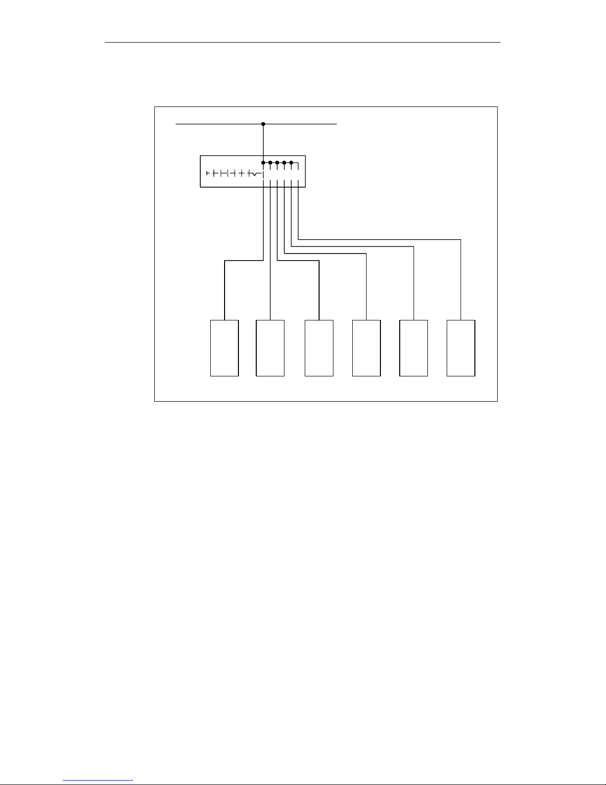
Example of wiring
L+
1
23456
7
123456
-S
X4.3X3.3 X3.4 X4.4 ...
Figure 2-2 Mode selector
2.2 Operating modes and press cycles
The 6 operating modes presented below can be selected in the parameterization
mask in the right section of Figure 2-1.
Please note the following rules:
• Each selected operating mode is associated with an enable mask, e.g. for start
and stop conditions, an external start and additional safety devices.
• The entries that are adjustable for a particular operating mode are indicated by
a white field. They have been assigned default parameters and are indicated
by a black dot.
• If conditions are being pre-assigned at additional terminals (start enables,
external start, etc.), an additional window for selecting the terminals
automatically appears in the mask.
• Irrelevant entries are grayed out and cannot be activated.
• An operating mode type can also have several parameterizations if, for
example, the number of safety devices varies.
• The Setup operating mode (operating mode 1) is predefined and cannot be
modified.
Operating modes
© Siemens AG 2003 All Rights Reserved
SIMOTION Safety Unit (AP) - Edition 06.2003
2-13
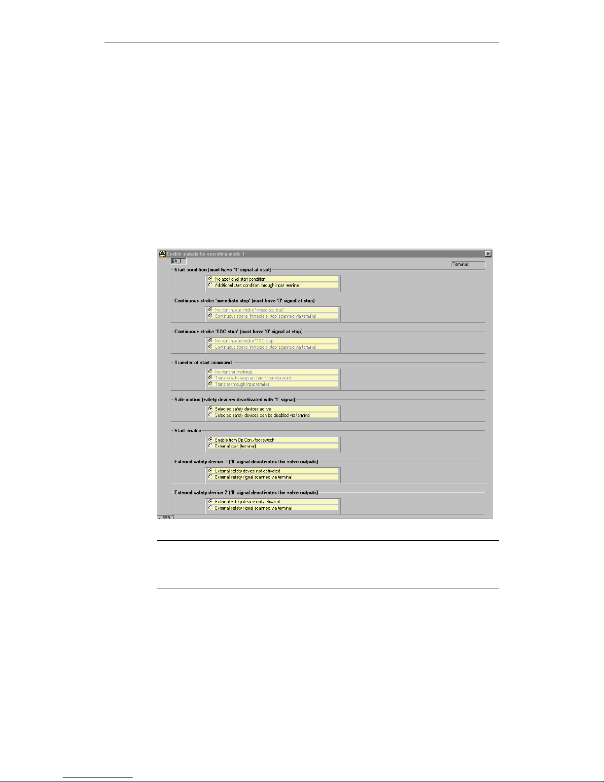
2.2.1 Setup (operating mode 1)
Definition
The press will only move while the two-hand buttons are being pressed. This is
also the case when the ram is moving upward. The press automatically comes to a
standstill at the end of each stroke (TDC). The operating elements must be
deactivated before a new start can be initiated.
A triple-action stop during a single stroke is not required with this control unit since
the Setup operating mode reaches the same level of safety as, for example, the
single stroke mode.
Parameterization
Figure 2-3 Enabling of operating mode 1
Note on "Safe motion" parameterization
When parameterizing "Selected safety device can be disabled via terminal", other
suitable safety measures must be effective for the specific machine when this
parameter is activated.
Operating modes
© Siemens AG 2003 All Rights Reserved
2-14 SIMOTION Safety Unit (AP) - Edition 06.2003
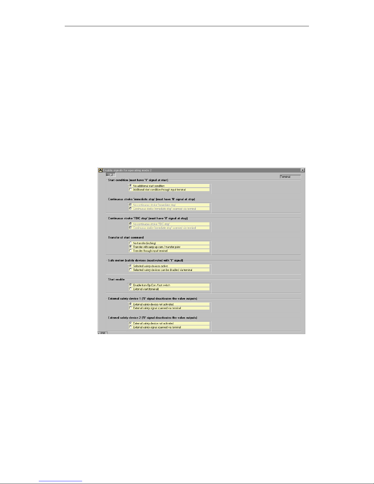
2.2.2 Single stroke (operating mode 2)
Definition
Pressure must be maintained on the two-hand buttons for activating the ram until
the hazardous closing movement is completed (just prior to the BDC). The press
then automatically moves back to the TDC and comes to a standstill. The press
can also be activated using a foot switch. In this case, however, suitable safety
measures (safety gate, light curtain) must be implemented that either make it
impossible to reach into the hazardous area with the hands during a closing
movement or that cause the machine to come to a standstill in the event of such an
action.
The same applies if the "Transfer through input terminal" parameter is selected for
the "Transfer of START command".
Parameterization
Figure 2-4 Enabling of operating mode 2
Operating modes
© Siemens AG 2003 All Rights Reserved
SIMOTION Safety Unit (AP) - Edition 06.2003
2-15
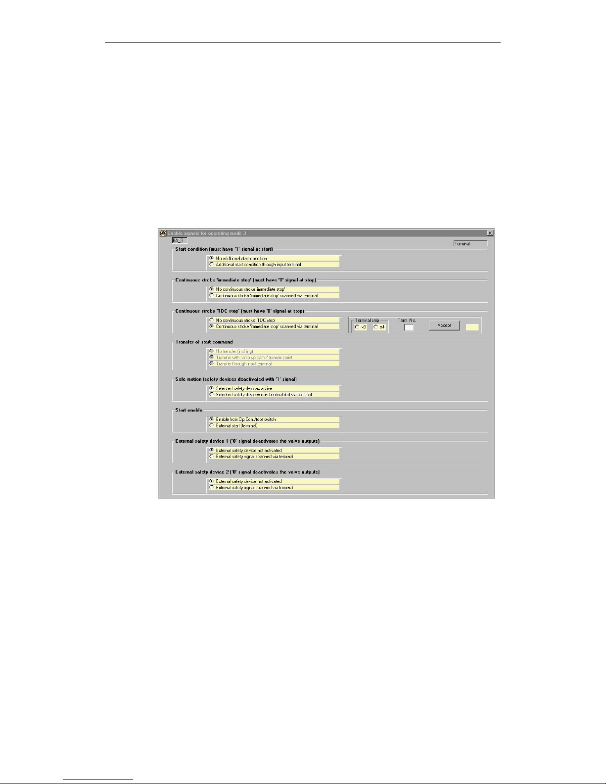
2.2.3 Continuous stroke (operating mode 3)
Definition
This operating mode requires the implementation of suitable safety measures and
an automated feed and removal of parts. After a start pulse, the press continues
running until it is brought to a standstill by a stop signal.
Depending on the selections made in the enable mask, the press either stops in
the TDC or comes to an immediate standstill.
Parameterization
Figure 2-5 Enabling of operating mode 3
Operating modes
© Siemens AG 2003 All Rights Reserved
2-16 SIMOTION Safety Unit (AP) - Edition 06.2003
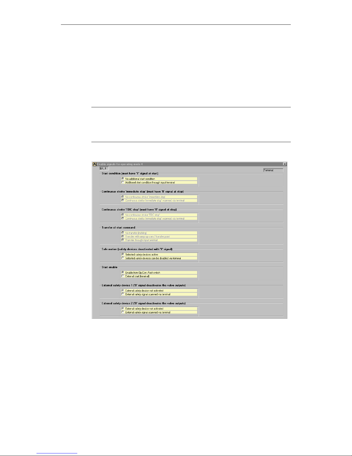
2.2.4 Changeover (operating mode 4)
Definition
This is not a production mode type. The production mode is deactivated in this
operating mode. In order to carry out an automatic changeover, e.g. to a new
production part, a standard control unit can be used to access the clutch and brake
(e.g. to adjust the stroke height).
Note
In this operating mode, the machine manufacturer must ensure that it is not
possible to initiate a hazardous stroke when the press is controlled by a standard
control unit. Safety measures may have to implemented to safeguard the
machine.
Parameterization
Figure 2-6 Enabling of operating mode 4
Operating modes
© Siemens AG 2003 All Rights Reserved
SIMOTION Safety Unit (AP) - Edition 06.2003
2-17
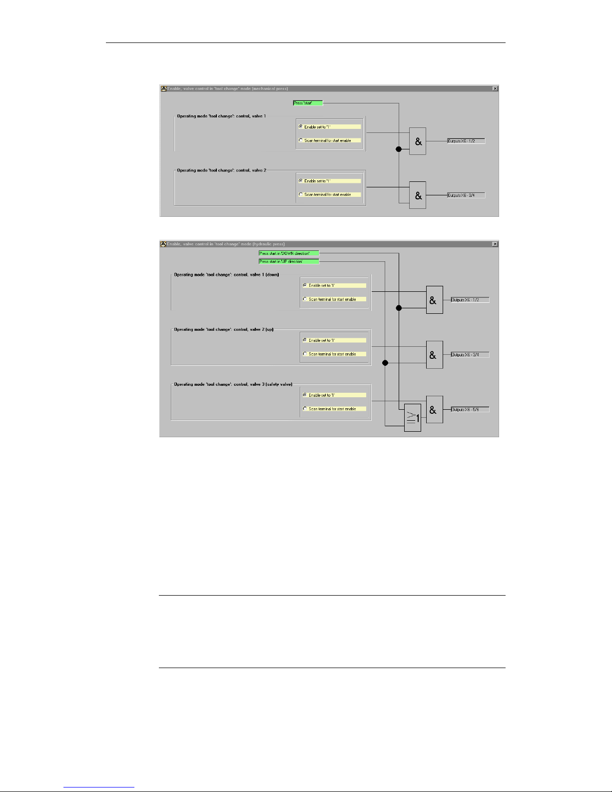
Figure 2-7 Valve control of mechanical press (mechanical operation)
Figure 2-8 Valve control of hydraulic press (hydraulic operation)
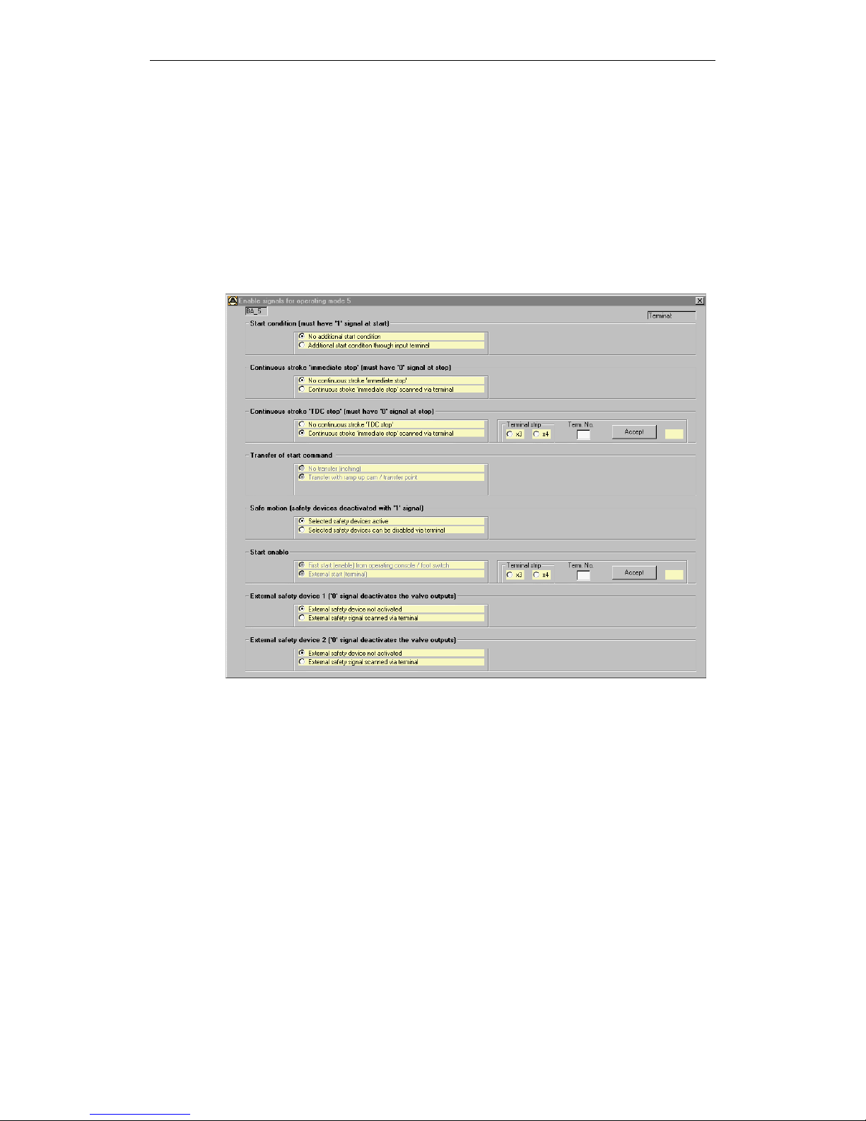
2.2.5 Automatic continuous stroke (operating mode 5)
Definition
This operating mode differs from the continuous mode in that two steps are
required to enable the machine for the first time:
• First, the automatic continuous stroke mode is enabled using the two-hand
control.
• Then the machine can be started by an external enable signal via the terminal.
Note
• If at the time of the two-hand activation there is an external enable signal, the
machine starts immediately.
• In this mode, the two-hand control acts as a command device only (not a
safety device). The operator must be protected by additional safety
equipment, e.g. ESPE!
Operating modes
© Siemens AG 2003 All Rights Reserved
2-18 SIMOTION Safety Unit (AP) - Edition 06.2003
Operating instructions
• The machine stops at the next BDC when the external enable signal ceases. It
can be restarted with this signal alone within the next 30 s.
• Two switching steps (see "Definition") are always required when a restart does
not take place within the next 30 s or when a safety device or a continuous
stroke stop (BDC or immediate stop) was activated.
Parameterization
Figure 2-9 Enabling of operating mode 5
Operating modes
© Siemens AG 2003 All Rights Reserved
SIMOTION Safety Unit (AP) - Edition 06.2003
2-19
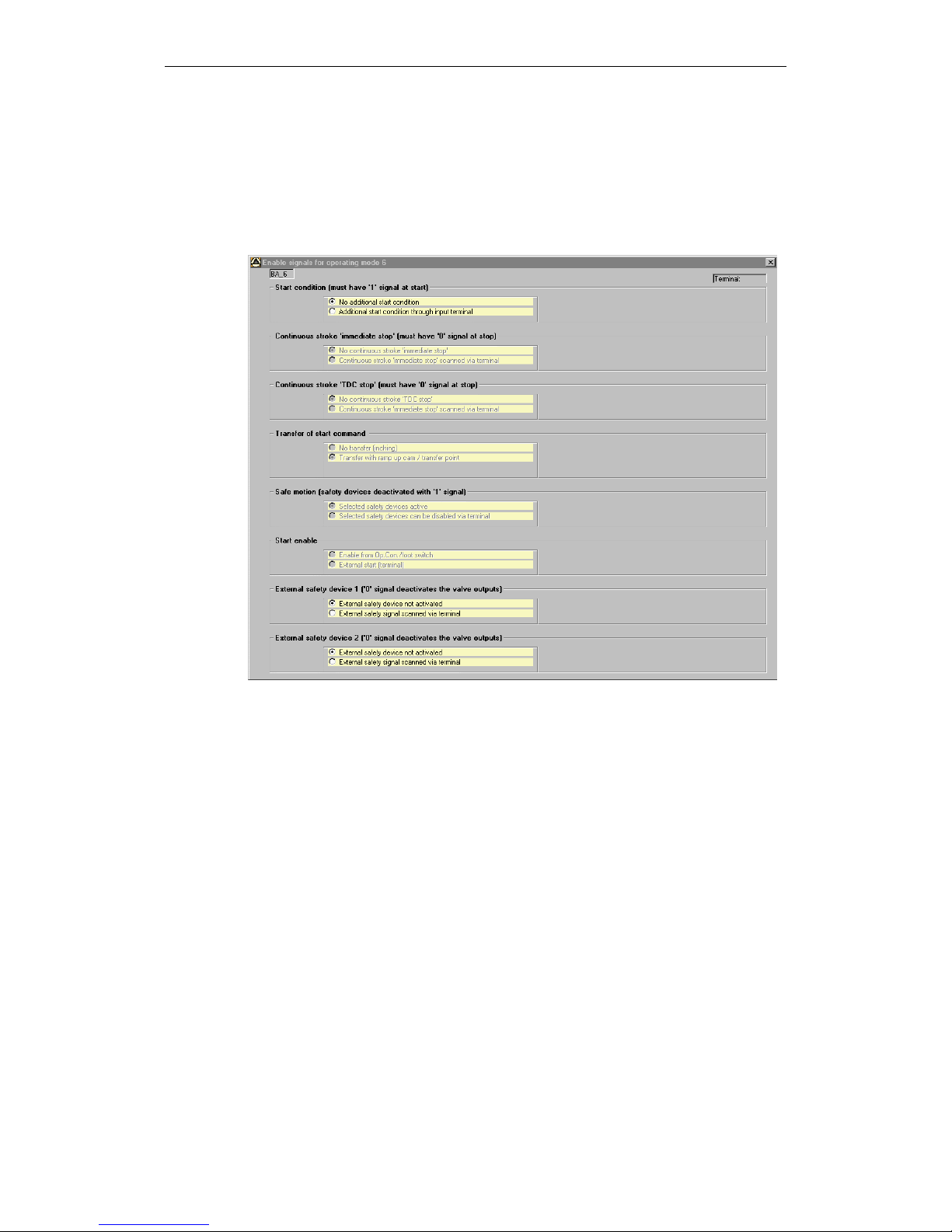
2.2.6 Single-stroke ESPE (operating mode 6)
Using a light curtain to control the press is described in the Control Elements
chapter.
Parameterization
Figure 2-10 Enabling of operating mode 6

Operating modes
© Siemens AG 2003 All Rights Reserved
2-20 SIMOTION Safety Unit (AP) - Edition 06.2003
Notes

© Siemens AG 2003 All Rights Reserved
SIMOTION Safety Unit (AP) - Edition 06.2003
3-21
3 Safety components
The contacts can be wired directly in the control unit. Additional contactors or
relays are not required. The following cyclical monitoring procedures are performed
in the program:
• Short circuit monitor between the two mutually isolated signal circuits.
• Discrepancy check of whether both switch-off circuits carry out a signal
change when the button is activated. The change between the two signals is
also monitored over time. The only elements that do not adhere to the preset
discrepancy time are the safety gate components.
The following components are available and can be combined as required:
• EMERGENCY OFF with restart inhibit (4x)
• EMERGENCY OFF without acknowledge (4x)
• Engaging lock (without acknowledge) (2x)
• Safety guard with restart inhibit (4x)
• Safety guard without acknowledge (4x)
• Safety gate with manual acknowledge (3x)
• Safety gate without manual acknowledge (3x)
Light curtains that are only used in the safety mode can be connected to the
existing safety guard components. For a description of their mode of operation, see
the Operating Elements chapter.
The parameterization of light curtains that are switched in safety and clock mode is
presented in the Operating Elements chapter.
Comments
• The EMERGENCY OFF that is activated in the parameterization is always
active for the entire control unit. It can, however, be deactivated for individual
operating modes (e.g. useful when creating different EMERGENCY OFF
circuits).
• The same applies to the engaging lock and the safety gate and safety guard
components. In this case, the safety devices can be specifically deselected in
the operating modes in which they are to be inactive.
Note
Without the implementation of additional safety measures, safety gates and
safety guards without a restart inhibit are not suitable for hazardous areas that
can be walked through.
3
Safety components
© Siemens AG 2003 All Rights Reserved
3-22 SIMOTION Safety Unit (AP) - Edition 06.2003
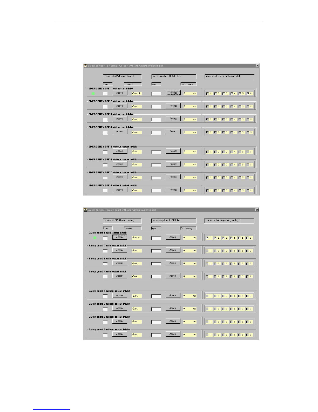
3.1 Parameterization of safety components
Figure 3-1 EMERGENCY OFF safety functions
Figure 3-2 Safety guard safety functions
Safety components
© Siemens AG 2003 All Rights Reserved
SIMOTION Safety Unit (AP) - Edition 06.2003
3-23
Comment
If the EMERGENCY OFF or the "Safety guard with restart inhibit" is selected, a
flashing fault lamp or, optionally, a separate alarm lamp (parameterizable)
indicates that the system is ready for acknowledgement.
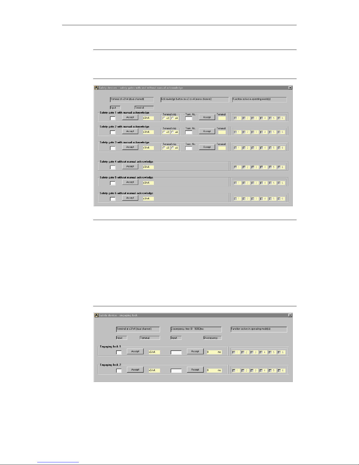
Figure 3-3 Safety gate safety functions
Note on safety gate with manual acknowledgement
Both contacts must be activated to open the safety gate. If only one contact is
activated and reclosed, an alarm is output with a continuous light. In this case,
both contacts will then have to be opened and reclosed.
The continuous light goes out after both contacts have been properly opened.
When the contacts are closed, a flashing signal indicates that the safety gate is
ready for acknowledgement. After the acknowledge button has been activated,
the machine is again ready to be started.
For safety gates without acknowledgement, there is no display if only one contact
is opened and reclosed due to an operation error. The problem is eliminated by
completely opening and reclosing the gate.
Figure 3-4 Engaging lock safety functions
 Loading...