

Page 1

SIMOTION
Motion Control
SIMOTION SCOUT
Valid as of Version 4.5
Preface
Fundamental safety
instructions
1
2
Configuration Manual
Introduction
Installation
User interface
Configuring/parameterizing
Target system
Upgrading and project
updates
Diagnostics
Service with SIMOTON
SCOUT
3
4
5
6
7
8
9
10
11/2016
Siemens SIMOTION
Diagnostics
Configuring a further
connection (such as HMI)
Product combinations
Technical specifications
Appendix
11
12
13
14
A
Page 2

Legal information
Warning notice system
This manual contains notices you have to observe in order to ensure your personal safety, as well as to prevent
damage to property. The notices referring to your personal safety are highlighted in the manual by a safety alert
symbol, notices referring only to property damage have no safety alert symbol. These notices shown below are
graded according to the degree of danger.
DANGER
indicates that death or severe personal injury will result if proper precautions are not taken.
WARNING
indicates that death or severe personal injury may result if proper precautions are not taken.
CAUTION
indicates that minor personal injury can result if proper precautions are not taken.
NOTICE
indicates that property damage can result if proper precautions are not taken.
If more than one degree of danger is present, the warning notice representing the highest degree of danger will be
used. A notice warning of injury to persons with a safety alert symbol may also include a warning relating to property
damage.
Qualified Personnel
The product/system described in this documentation may be operated only by personnel qualified for the specific
task in accordance with the relevant documentation, in particular its warning notices and safety instructions. Qualified
personnel are those who, based on their training and experience, are capable of identifying risks and avoiding
potential hazards when working with these products/systems.
Proper use of Siemens products
Note the following:
WARNING
Siemens products may only be used for the applications described in the catalog and in the relevant technical
documentation. If products and components from other manufacturers are used, these must be recommended or
approved by Siemens. Proper transport, storage, installation, assembly, commissioning, operation and
maintenance are required to ensure that the products operate safely and without any problems. The permissible
ambient conditions must be complied with. The information in the relevant documentation must be observed.
Trademarks
All names identified by ® are registered trademarks of Siemens AG. The remaining trademarks in this publication
may be trademarks whose use by third parties for their own purposes could violate the rights of the owner.
Disclaimer of Liability
We have reviewed the contents of this publication to ensure consistency with the hardware and software described.
Since variance cannot be precluded entirely, we cannot guarantee full consistency. However, the information in
this publication is reviewed regularly and any necessary corrections are included in subsequent editions.
Siemens AG
Division Digital Factory
Postfach 48 48
90026 NÜRNBERG
GERMANY
Ⓟ 10/2016 Subject to change
Copyright © Siemens AG 2016.
All rights reserved
Page 3

Table of contents
1 Preface.........................................................................................................................................................9
1.1 Validity......................................................................................................................................9
1.2 Sections in this manual............................................................................................................9
1.3 SIMOTION Documentation....................................................................................................10
1.4 Hotline and Internet addresses..............................................................................................10
2 Fundamental safety instructions.................................................................................................................13
2.1 General safety instructions.....................................................................................................13
2.2 Industrial security...................................................................................................................14
2.3 Danger to life due to software manipulation when using removable storage media..............15
3 Introduction.................................................................................................................................................17
3.1 Content of the configuring manual.........................................................................................17
3.2 SIMOTION SCOUT engineering system................................................................................17
3.3 SIMOTION hardware platforms..............................................................................................18
3.4 Programming languages........................................................................................................19
3.4.1 Programming languages in SIMOTION SCOUT....................................................................19
3.4.2 Motion Control Chart (MCC)..................................................................................................21
3.4.3 Ladder Logic / Function Block Diagram (LAD/FBD)...............................................................22
3.4.4 Structured Text (ST)...............................................................................................................23
3.5 CamEdit cam editor................................................................................................................24
3.6 CamTool options package.....................................................................................................24
3.7 Technology packages and technology objects......................................................................25
3.8 CLib Studio option package...................................................................................................26
4 Installation..................................................................................................................................................27
4.1 SCOUT and SCOUT Standalone system requirements........................................................27
4.2 Installing SIMOTION SCOUT.................................................................................................27
4.2.1 Installing SIMOTION SCOUT.................................................................................................27
4.2.2 Installing SIMOTION SCOUT Standalone.............................................................................28
4.2.3 SINAMICS Support Package (SSP).......................................................................................29
4.3 Uninstalling SIMOTION SCOUT ...........................................................................................29
4.4 Licenses.................................................................................................................................30
4.4.1 To install the authorization.....................................................................................................30
4.4.2 Saving and moving the license key........................................................................................31
5 User interface.............................................................................................................................................33
5.1 SIMOTION SCOUT - workbench...........................................................................................33
SIMOTION SCOUT
Configuration Manual, 11/2016 3
Page 4

Table of contents
5.2 SIMOTION SCOUT - working area........................................................................................35
5.3 SIMOTION SCOUT project navigator ...................................................................................36
5.3.1 Using the project navigator....................................................................................................36
5.3.2 Creating elements..................................................................................................................37
5.3.3 Inserting a folder....................................................................................................................39
5.3.4 Changing properties of the elements.....................................................................................40
5.3.5 Wizards for configuration support..........................................................................................41
5.4 SIMOTION SCOUT - menus..................................................................................................41
5.5 SIMOTION SCOUT - menu items..........................................................................................44
5.6 SIMOTION SCOUT - keyboard operation and shortcuts.......................................................49
5.7 SIMOTION SCOUT - using the context menus......................................................................50
5.8 SIMOTION SCOUT - detailed view........................................................................................51
5.8.1 Using the detail view..............................................................................................................51
5.8.2 Using the symbol browser......................................................................................................51
5.8.3 Address list.............................................................................................................................52
5.8.4 Watch table............................................................................................................................52
5.8.5 Working with lists...................................................................................................................54
5.9 SIMOTION SCOUT - language settings................................................................................54
5.10 SIMOTION SCOUT - using help............................................................................................54
5.10.1 SIMOTION SCOUT Online Help............................................................................................54
5.10.2 Searching in the online help...................................................................................................60
5.10.3 Getting Started with SIMOTION SCOUT...............................................................................61
5.10.4 Error remedy..........................................................................................................................62
5.11 Adding add-ons to the workbench..........................................................................................63
6 Configuring/parameterizing........................................................................................................................65
6.1 Configuration overview...........................................................................................................65
6.2 SIMOTION SCOUT - basic settings.......................................................................................65
6.3 Managing projects..................................................................................................................66
6.3.1 SIMOTION SCOUT project....................................................................................................66
6.3.2 Creating a new project...........................................................................................................67
6.3.3 Open project...........................................................................................................................70
6.3.4 Saving and compiling.............................................................................................................71
6.3.5 Performing a consistency check............................................................................................72
6.3.6 Archiving and backing up projects on memory cards.............................................................72
6.3.7 Exporting and importing a project in XML format...................................................................73
6.3.8 Searching in the project.........................................................................................................74
6.3.9 Replacing in the project..........................................................................................................76
6.3.10 Printing projects.....................................................................................................................76
6.4 Configuring devices................................................................................................................77
6.4.1 Adding a SIMOTION device...................................................................................................77
6.4.1.1 Starting HW Config................................................................................................................78
6.4.1.2 The HW Config program........................................................................................................79
6.4.1.3 HW Config: Opening the hardware catalog............................................................................79
6.4.1.4 SIMOTION devices in the hardware catalog..........................................................................80
6.4.2 Selecting technology packages..............................................................................................80
SIMOTION SCOUT
4 Configuration Manual, 11/2016
Page 5

Table of contents
6.4.3 Connecting to the target system............................................................................................82
6.4.3.1 Installing the interface card....................................................................................................82
6.4.3.2 Set PG/PC interface...............................................................................................................84
6.4.3.3 Specifying the access point....................................................................................................85
6.4.3.4 Communication via PROFIBUS DP.......................................................................................86
6.4.3.5 Ethernet communication........................................................................................................87
6.4.3.6 Communication via PROFINET.............................................................................................87
6.4.4 Inserting a drive......................................................................................................................88
6.4.4.1 Drives with SIMOTION...........................................................................................................88
6.4.4.2 Inserting a SINAMICS drive on PROFIBUS DP.....................................................................89
6.4.4.3 Inserting a SINAMICS drive on PROFINET IO......................................................................90
6.4.4.4 Commissioning the drives......................................................................................................91
6.4.4.5 SINAMICS S120 on SIMOTION.............................................................................................92
6.4.4.6 Configuring the infeed............................................................................................................94
6.4.4.7 Testing the drive with the drive control panel.........................................................................96
6.5 Creating and testing an axis.................................................................................................100
6.5.1 TO axis technology object....................................................................................................100
6.5.2 Configuring Axes..................................................................................................................102
6.5.3 Testing the axis with the axis control panel..........................................................................106
6.6 Programming the SIMOTION application.............................................................................110
6.6.1 Using tags............................................................................................................................110
6.6.2 Using MCC...........................................................................................................................113
6.6.2.1 Overview..............................................................................................................................113
6.6.2.2 Creating the MCC unit..........................................................................................................114
6.6.2.3 Creating an MCC chart........................................................................................................115
6.6.2.4 Using MCC command blocks...............................................................................................117
6.6.2.5 Backing up the MCC program..............................................................................................119
6.6.3 Using LAD/FBD....................................................................................................................120
6.6.3.1 Overview..............................................................................................................................120
6.6.3.2 Create LAD/FBD unit...........................................................................................................121
6.6.3.3 Create LAD/FBD program....................................................................................................122
6.6.3.4 Using the LAD/FBD toolbar..................................................................................................124
6.6.3.5 Backing up the LAD/FBD program.......................................................................................125
6.6.4 Using ST..............................................................................................................................125
6.6.4.1 Overview..............................................................................................................................125
6.6.4.2 Creating an ST source.........................................................................................................126
6.6.4.3 Backing up the ST program ................................................................................................127
6.6.4.4 Executing the ST program...................................................................................................128
6.7 Configure execution system.................................................................................................128
6.8 Project generator..................................................................................................................131
6.8.1 Overview..............................................................................................................................131
6.8.2 Integrating the ProjectGenerator..........................................................................................132
6.9 Configuring multilingual messages......................................................................................132
6.10 Know-how Protection...........................................................................................................133
6.11 Saving and restoring variables from the device...................................................................134
6.12 Online multiuser mode.........................................................................................................137
6.12.1 Overview..............................................................................................................................137
6.12.2 Working in online multiuser mode........................................................................................139
SIMOTION SCOUT
Configuration Manual, 11/2016 5
Page 6

Table of contents
6.13 Licensing runtime.................................................................................................................140
6.13.1 Licensing of the runtime components..................................................................................140
6.13.1.1 Overview for the licensing....................................................................................................140
6.13.1.2 Licenses and license key ....................................................................................................140
6.13.1.3 Determining licensing requirements.....................................................................................141
6.13.1.4 Displaying existing licenses of the SIMOTION device.........................................................142
6.13.1.5 Performing the licensing.......................................................................................................143
6.13.2 Changing the license key.....................................................................................................144
6.13.3 License key is protected from being deleted (as from Kernel V4.1).....................................144
6.13.4 Licensing during hardware replacement..............................................................................144
6.13.5 Underlicensing.....................................................................................................................144
6.14 Writing the boot sector.........................................................................................................145
7 Target system...........................................................................................................................................147
7.1 Overview..............................................................................................................................147
7.2 Going online/offline with SIMOTION SCOUT ......................................................................148
7.2.1 Online access points............................................................................................................148
7.2.2 Available nodes....................................................................................................................149
7.2.3 Setting the access point on the PG/PC................................................................................151
7.2.4 Select target devices............................................................................................................152
7.3 Controlling the operating mode with SIMOTION SCOUT....................................................154
7.4 Overall reset.........................................................................................................................160
7.5 Setting the time of day.........................................................................................................161
7.6 Loading data to the target system........................................................................................161
7.7 Archive project data to memory card...................................................................................162
7.8 Loading to the file system....................................................................................................162
8 Upgrading and project updates................................................................................................................163
8.1 General information..............................................................................................................163
8.2 Upgrading and changing platforms for a SIMOTION device................................................163
8.2.1 Changing a SIMOTION device and subsequent TP upgrade (within a platform).................163
8.2.2 Changing the SIMOTION platform.......................................................................................165
8.2.3 Upgrading technology packages.........................................................................................166
8.3 Upgrading devices and project updates using the device update tool ................................168
9 Diagnostics...............................................................................................................................................173
9.1 Overview of the possible diagnostic functions.....................................................................173
9.2 Using the diagnostics overview............................................................................................174
9.3 Device diagnostics...............................................................................................................174
9.3.1 Device diagnostics...............................................................................................................174
9.3.2 Device diagnostics: General................................................................................................175
9.3.3 Device diagnostics: Diagnostics buffer................................................................................176
9.3.4 Device diagnostics: Task Manager......................................................................................177
9.3.5 Device diagnostics: Checking memory utilization................................................................180
9.3.6 Device diagnostics: Checking the system utilization............................................................181
9.3.7 Device diagnostics: User log file..........................................................................................182
SIMOTION SCOUT
6 Configuration Manual, 11/2016
Page 7

Table of contents
9.3.8 Device diagnostics: Syslog file.............................................................................................183
9.3.9 Device diagnostics: Version overview..................................................................................183
9.3.10 Device diagnostics: Alarms..................................................................................................184
9.4 Diagnostic functions in the address list................................................................................185
9.5 Interconnection overview.....................................................................................................186
9.6 Service Overview.................................................................................................................187
9.7 Trace and measuring functions............................................................................................188
9.7.1 Trace, measuring function, and automatic controller setting................................................188
9.7.2 Task Trace...........................................................................................................................189
9.7.3 Technology object trace.......................................................................................................190
9.8 Accessible nodes.................................................................................................................192
9.9 Program testing and debugging...........................................................................................193
9.10 Project comparison..............................................................................................................193
9.11 Project overview...................................................................................................................196
9.12 Services and diagnostics without an Engineering System...................................................196
10 Service with SIMOTON SCOUT...............................................................................................................197
10.1 Selecting the right project with SCOUT................................................................................197
10.2 Project was created in Version V4.1 / V4.2 / V4.3 / V4.4.....................................................199
10.3 Project V4.1 / V4.2 / V4.3 / V4.4 has been edited with SCOUT V4.5..................................200
10.4 Introduction of versioning with standard library and software components..........................201
11 Siemens SIMOTION Diagnostics.............................................................................................................203
12 Configuring a further connection (such as HMI).......................................................................................205
12.1 Rules for arranging modules in the HW Config....................................................................205
12.2 Routing.................................................................................................................................206
12.3 HMI (Human Machine Interface) connection........................................................................206
12.4 Higher-level automation systems.........................................................................................208
12.5 TCP ports for access to SIMOTION/SINAMICS..................................................................208
13 Product combinations...............................................................................................................................211
13.1 Compatibility.........................................................................................................................211
13.1.1 General compatibility............................................................................................................211
13.1.2 Software compatibility..........................................................................................................211
13.2 Memory media of the SIMOTION devices...........................................................................212
13.3 STEP 7.................................................................................................................................213
13.3.1 SIMATIC Manager...............................................................................................................213
13.3.2 SIMATIC Logon....................................................................................................................213
13.3.3 SIMATIC Version Trail.........................................................................................................217
13.4 NetPro..................................................................................................................................218
13.5 HMI.......................................................................................................................................219
SIMOTION SCOUT
Configuration Manual, 11/2016 7
Page 8

Table of contents
13.6 Drive ES...............................................................................................................................220
13.7 Commissioning drives (STARTER)......................................................................................221
13.8 CamTool...............................................................................................................................222
13.9 DCC programming system...................................................................................................222
14 Technical specifications............................................................................................................................225
14.1 Quantity framework..............................................................................................................225
14.2 Memory requirement............................................................................................................225
A Appendix...................................................................................................................................................227
A.1 Scripts for SIMOTION..........................................................................................................227
A.2 Creating an example program for axis positioning in SIMOTION SCOUT...........................227
Index.........................................................................................................................................................239
SIMOTION SCOUT
8 Configuration Manual, 11/2016
Page 9

Preface
1.1 Validity
This document is part of the Engineering System Handling documentation package.
Validity
This manual is valid for SIMOTION SCOUT in conjunction with the SIMOTION CamTool
optional package for product version V4.5.
1.2 Sections in this manual
The following is a list of sections included in this manual along with a description of the
information presented in each section.
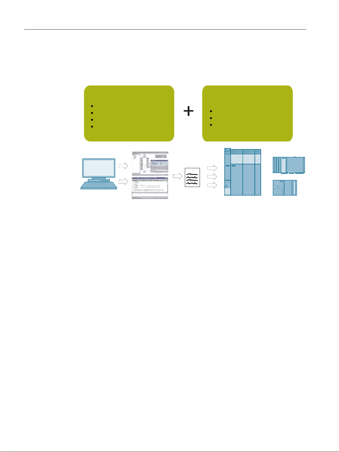
● Introduction
This chapter contains an overview of the SIMOTION SCOUT Engineering System.
● Installation
This chapter contains the system requirements for SIMOTION SCOUT, describes the
procedure for installing and uninstalling it, and provides important information on the
communications link to the SIMOTION device.
1
● User interface
This chapter contains an overview of the SIMOTION SCOUT Workbench. It also provides
notes concerning the language setting and the use of online help.
● Configuring/parameterizing
This chapter describes the basic steps for operating SIMOTION SCOUT.
● Target system
This chapter contains information on controlling the target system. You also learn how you
can control the operating state with SIMOTION SCOUT and how you can upload data to
the target system.
● Diagnostics
This chapter contains information about which diagnostic functions are available and how
these are operated.
● Service with SIMOTION SCOUT
This chapter contains information about the service.
● Siemens SIMOTION Diagnostics
This chapter contains information on how you can use the Siemens Simotion Diagnostics
diagnostic tool for troubleshooting.
● Configuring a further connection (such as HMI)
This chapter contains information on how to configure the HMI connection among other
things.
SIMOTION SCOUT
Configuration Manual, 11/2016 9
Page 10

Preface
1.4 Hotline and Internet addresses
● Product combinations
This chapter describes topics such as compatibility and storage media as well as STEP 7,
NetPro, Drive ES, HMI, and other interfaces.
● Technical specifications
This chapter contains information about the quantity structure and the storage capacity
requirement.
● Appendix
The appendix contains the scripts for SIOMTION and a sample program for an axis
configuration in SIOMOTION SCOUT.
● Index
1.3 SIMOTION Documentation
An overview of the SIMOTION documentation can be found in the SIMOTION Documentation
Overview document.
This documentation is included as electronic documentation in the scope of delivery of
SIMOTION SCOUT. It comprises ten documentation packages.
The following documentation packages are available for SIMOTION V4.5:
● SIMOTION Engineering System Handling
● SIMOTION System and Function Descriptions
● SIMOTION Service and Diagnostics
● SIMOTION IT
● SIMOTION Programming
● SIMOTION Programming - References
● SIMOTION C
● SIMOTION P
● SIMOTION D
● SIMOTION Supplementary Documentation
1.4 Hotline and Internet addresses
SIMOTION at a glance
We have compiled an overview page from our range of information about SIMOTION with the
most important information on frequently asked topics - which can be opened with only one
click.
Whether beginner or experienced SIMOTION user – the most important downloads, manuals,
tutorials, FAQs, application examples, etc. can be found at
https://support.industry.siemens.com/cs/ww/en/view/109480700
SIMOTION SCOUT
10 Configuration Manual, 11/2016
Page 11

Additional information
Click the following link to find information on the following topics:
● Documentation overview
● Additional links to download documents
● Using documentation online (find and search manuals/information)
https://support.industry.siemens.com/cs/ww/en/view/109479653
My Documentation Manager
Click the following link for information on how to compile documentation individually on the
basis of Siemens content and how to adapt it for the purpose of your own machine
documentation:
https://support.industry.siemens.com/My/ww/en/documentation
Training
Click the following link for information on SITRAIN - Siemens training courses for automation
products, systems and solutions:
Preface
1.4 Hotline and Internet addresses
FAQs
Technical support
http://www.siemens.com/sitrain
Frequently Asked Questions can be found in SIMOTION Utilities & Applications, which are
included in the scope of delivery of SIMOTION SCOUT, and in the Service&Support pages in
Product Support:
https://support.industry.siemens.com/cs/de/en/ps/14505/faq
Country-specific telephone numbers for technical support are provided on the Internet under
Contact:
https://support.industry.siemens.com/cs/ww/en/sc/2090
SIMOTION SCOUT
Configuration Manual, 11/2016 11
Page 12

Preface
1.4 Hotline and Internet addresses
SIMOTION SCOUT
12 Configuration Manual, 11/2016
Page 13

Fundamental safety instructions
2.1 General safety instructions
WARNING
Danger to life if the safety instructions and residual risks are not observed
The non-observance of the safety instructions and residual risks stated in the associated
hardware documentation can result in accidents with severe injuries or death.
● Observe the safety instructions given in the hardware documentation.
● Consider the residual risks for the risk evaluation.
WARNING
Danger to life caused by machine malfunctions caused by incorrect or changed
parameterization
Incorrect or changed parameterization can cause malfunctions on machines that can result
in injuries or death.
● Protect the parameterization (parameter assignments) against unauthorized access.
● Respond to possible malfunctions by applying suitable measures (e.g. EMERGENCY
STOP or EMERGENCY OFF).
2
SIMOTION SCOUT
Configuration Manual, 11/2016 13
Page 14

Fundamental safety instructions
2.2 Industrial security
2.2 Industrial security
Note
Industrial security
Siemens provides products and solutions with industrial security functions that support the
secure operation of plants, systems, machines and networks.
In order to protect plants, systems, machines and networks against cyber threats, it is
necessary to implement – and continuously maintain – a holistic, state-of-the-art industrial
security concept. Siemens’ products and solutions only form one element of such a concept.
Customer is responsible to prevent unauthorized access to its plants, systems, machines and
networks. Systems, machines and components should only be connected to the enterprise
network or the internet if and to the extent necessary and with appropriate security measures
(e.g. use of firewalls and network segmentation) in place.
Additionally, Siemens’ guidance on appropriate security measures should be taken into
account. For more information about industrial security, please visit http://www.siemens.com/
industrialsecurity.
Siemens’ products and solutions undergo continuous development to make them more secure.
Siemens strongly recommends to apply product updates as soon as available and to always
use the latest product versions. Use of product versions that are no longer supported, and
failure to apply latest updates may increase customer’s exposure to cyber threats.
To stay informed about product updates, subscribe to the Siemens Industrial Security RSS
Feed under http://www.siemens.com/industrialsecurity..
WARNING
Danger as a result of unsafe operating states resulting from software manipulation
Software manipulation (e.g. by viruses, Trojan horses, malware, worms) can cause unsafe
operating states to develop in your installation which can lead to death, severe injuries and/
or material damage.
● Keep the software up to date.
Information and newsletters can be found at:
http://support.automation.siemens.com
● Incorporate the automation and drive components into a state-of-the-art, integrated
industrial security concept for the installation or machine.
For more detailed information, go to:
http://www.siemens.com/industrialsecurity
● Make sure that you include all installed products into the integrated industrial security
concept.
SIMOTION SCOUT
14 Configuration Manual, 11/2016
Page 15

Fundamental safety instructions
2.3 Danger to life due to software manipulation when using removable storage media
2.3 Danger to life due to software manipulation when using removable
storage media
WARNING
Danger to life due to software manipulation when using removable storage media
The storage of files on removable storage media involves a high risk of infection, e.g. via
viruses or malware. Incorrect parameter assignment can cause machines to malfunction,
which can lead to injuries or death.
● Protect the files on removable storage media against harmful software through appropriate
protective measures, e.g. virus scanners.
SIMOTION SCOUT
Configuration Manual, 11/2016 15
Page 16

Fundamental safety instructions
2.3 Danger to life due to software manipulation when using removable storage media
SIMOTION SCOUT
16 Configuration Manual, 11/2016
Page 17

Introduction
3.1 Content of the configuring manual
The SIMOTION SCOUT Configuration Manual is a general description of the software. Not all
available software functions are described in this document. All detailed, subject-specific
information can be found in the context-sensitive online help and the corresponding
documentation.
Important notes and information on the SIMOTION Motion Control system are contained in
the following catalog:
● SIMOTION, SINAMICS S120 and Motors for Production Machines, PM 21 Catalog
3.2 SIMOTION SCOUT engineering system
Introduction
While the Motion Control system SIMOTION provides a wide variety of preprogrammed
functions, it is also parameterizable and programmable for individual requirements. Highperformance tools, which provide optimum support and ease of use for the necessary
engineering steps, are required for this.
3
The SIMOTION SCOUT Engineering System is the environment for the uniform automation
of production machines with SIMOTION and integrates into the SIMATIC environment in
accordance with TIA (Totally Integrated Automation).
SIMOTION SCOUT provides a uniform, function-oriented view for your automation task, and
at the same time it is very easy to use.
The possible SIMOTION applications range from simple, parameterizable, speed-controlled
single axes through to complex, mechatronically-coupled and programmable multi-axis
machines. Therefore, SIMOTION SCOUT provides views adapted to the task and can be
expanded with additional tools (e.g. tool for the graphic creation of cams).
SIMOTION SCOUT is the engineering system for SIMOTION. It is integrated into STEP 7 and
provides all the required tools for the following functionalities:
● Configuration
● Parameter assignment
● Programming
● Test
● Diagnostics
SIMOTION SCOUT
Configuration Manual, 11/2016 17
Page 18
6,027,21'6,027,21&
6,027,213
21(UXQWLPHV\VWHPIRU
YDULRXVSODWIRUPV
7HFKQRORJ\SDFNDJHV+DUGZDUHSODWIRUPV6,027,216&287
HQJLQHHULQJV\VWHP
21(6&287HQJLQHHULQJV\VWHP
57FRGH
IRUFRQILJXULQJ
SDUDPHWHUL]LQJJUDSKLFRU
WH[WXDOSURJUDPPLQJ
IRUGLDJQRVWLFVWURXEOHVKRR
WLQJGHEXJJLQJ
&RQWUROOHUEDVHG6,027,21&
3&EDVHG6,027,213
'ULYHEDVHG6,027,21'
Introduction
3.3 SIMOTION hardware platforms
The following tasks are graphically supported with operator guidance:
● Creation of the hardware and network configuration
● Creation, configuration and parameter assignment of technology objects
such as axes, output cams and cams.
Figure 3-1 SIMOTION system overview
The automation topology is defined in the first engineering steps. The hardware and network
configuration is created by parameterizing the required components and networks.
3.3 SIMOTION hardware platforms
To meet the complex requirements of machine construction, SIMOTION offers three hardware
variants with different performance, packaging formats and expandability options. The basic
system characteristics, like the engineering, are identical.
SIMOTION D (Drive-based)
SIMOTION D is a compact, drive-based version of SIMOTION based on the SINAMICS S120
drives family. For SIMOTION D, the SIMOTION runtime environment and the SINAMICS drive
software run concurrently on the controller hardware in the SINAMICS S120 packaging format.
SIMOTION P (PC-based)
SIMOTION P is a PC-based, open motion control system from SIMOTION. Control, motion
control, and HMI functions are executed together with standard PC applications on the
SIMOTION P hardware platform.
SIMOTION SCOUT
18 Configuration Manual, 11/2016
Page 19

SIMOTION P combines the openness of the Windows operating system with the real-time
capability of SIMOTION P Runtime.
SIMOTION C (Controller-based)
SIMOTION C is the modular controller variant in the tried and trusted packaging system of the
SIMATIC S7-300 with its very varied expandability options on the I/O bus. SIMOTION C240
high-performance motion controllers are available for control functions and motion control
tasks. The integrated interface for four analog coupled drives makes the SIMOTION C
particularly suitable for compact applications with the control of analog electrical drives and
the operation of hydraulic axes. SIMOTION C also supports operation of four stepper motors
at these interfaces. SIMOTION C240 PN offers a PROFINET interface instead of the encoder
and drive interfaces.
3.4 Programming languages
Introduction
3.4 Programming languages
3.4.1 Programming languages in SIMOTION SCOUT
SIMOTION provides different programming languages for the solution of Motion Control tasks,
control logic, arithmetic calculations, etc. During runtime, the selected programming language
has no effect – except in the different displays when debugging. You can create user
applications in different programming languages and use them jointly in a project.
The following programming languages are available in SIMOTION SCOUT:
● Motion Control Chart (MCC)
Graphical programming as a flow chart.
In particular, for sequential tasks with a high level of motion control functionality.
● Ladder Logic / Function Block Diagram (LAD/ FBD)
Graphical Programming as Ladder Logic / Function Block Diagram, supplemented by
Motion Control Functions via PLCopen Function Blocks.
In particular, for cyclic tasks with a high logic proportion.
● Structured Text (ST)
textual programming in a high-level language.
As the base language of the SIMOTION system, ST supports all system features and
functions of the technology packages and is thus suitable for all tasks.
● Drive Control Chart (DCC)
In many applications, the control of the drive system requires a linking logic which combines
multiple statuses (e.g. entry control, system status) into one control signal (e.g. ON
command).
As well as logical links, drive systems are increasingly calling for arithmetic operations and/
or saving elements. This kind of functionality is available on drive objects of the SINAMICS
drive system and the SIMOTION control system in the form of a Drive Control Chart (DCC).
With the Drive Control Chart Editor (DCC Editor) based on CFC, SIMOTION controllers
and SINAMICS drives can be configured graphically.
For further information, see Section DCC programming system (Page 222).
SIMOTION SCOUT
Configuration Manual, 11/2016 19
Page 20

Introduction
3.4 Programming languages
Sources (units)
Programs are created in program containers, the so-called sources (units). They are compiled
in the engineering system. Any errors or warnings that occur during compilation are output in
the diagnostics window. Sources compiled without error can then be loaded into the associated
controller.
A source contains any number of programs, functions, function blocks and classes. Each
executable part of a source (program, function, function block, class) is called a POU (Program
Organization Unit).
A source is divided into an interface and an implementation section.
Interface section
All parts exported by the source are defined in the interface section. Other sources and external
components (e.g. HMI systems) can access these parts. These include user-defined data
types, data (variables and constants) as well as names of programs, functions, and function
blocks.
Implementation section
Tasks
The data types and data defined in the implementation section are global throughout the source
and can be used by all POUs. The implementation section also contains the program code of
the POUs. Any POUs not specified in the interface section can only be used within the source.
Note
Source concept
The source concept with encapsulation of code and data allows you to structure applications.
For example, the functionality of an entire machine module with a defined external interface
can be implemented in a single source.
Programs are processed in tasks. A task is a job which is executed in a certain chronological
sequence. The advantage of the task system (execution system) is that processes appended
to the appropriate task levels can run simultaneously.
The SIMOTION Motion Control system uses high-performance CPUs on which a real-time
operating system - suitable for fast control processes - is implemented. Each task is allocated
a slice of the computing time. The organization of the task executions is performed by the
operating system. A differentiation is made between user and system tasks that are
independent of one another.
Additional references
For detailed information on the programming languages and the execution system, refer to the
SIMOTION SCOUT online help and the appropriate programming and operating manuals.
SIMOTION SCOUT
20 Configuration Manual, 11/2016
Page 21

3.4.2 Motion Control Chart (MCC)
MCC (Motion Control Chart) is a "flow diagram language" that graphically formulates the
process sequences in production machines in a simple manner. The result is one or more flow
diagrams, comprising MCC blocks that describe the chronological sequence of the individual
machine actions. Due to its special means of expression, an MCC is ideally suited to
programming sequential processes.
Motion Control Chart supports the simple description of the motion sequences of machines
using powerful motion control commands, such as reference axis, position axis, synchronize
or desynchronize cam, and many more.
To control the machine sequence, commands are available for awaiting conditions and for
formulating computations, as well as for programming various control structures, such as
polling (IF), case determination (CASE) and loops (FOR, WHILE, UNTIL). Several MCC
programs may be created to describe different process situations. For example, you can create
one MCC program to bring the machine to a defined initial state when it is switched on, a
second MCC program for the normal production sequence, and a third MCC program to specify
what the machine has to do in the event of a fault.
All MCC blocks – a selection of the most important SIMOTION functions – are available in tool
bars. They are grouped according to function and are automatically inserted in the flow diagram
at the marked point by means of a click. A click on the individual elements opens specific
dialogs for parameterization. Obviously, you can also add your own comments for the further
documentation of the process sequence. Functions from the SIMOTION command library that
are not individually offered as MCC blocks can be used in an MCC program by means of a
special command.
Introduction
3.4 Programming languages
Performance features:
● Easy-to-use due to graphical illustration in the form of flow diagrams
● Hierarchical command library for motion control, PLC, and technology functions
● Control structures (IF, WHILE, CASE, etc.)
● Zooming for LAD, FBD and ST
● Subroutine calls (FB/FC, programs, methods (OOP))
● Structuring based on command module generation, i.e. combination of command
sequences to form a module command
● User-friendly debug functions for online test and diagnosis, for example, single-step,
program status or breakpoints for easier troubleshooting (debugging)
● Monitor, trace
Note
Implicit conversion to ST
When being compiled, programs written in MCC are implicitly converted to ST programs and
then compiled.
You can export the intermediate result as an ST and use it as a basis for your own ST programs.
SIMOTION SCOUT
Configuration Manual, 11/2016 21
Page 22

Introduction
3.4 Programming languages
Additional references
Detailed information can be found in the SIMOTION SCOUT online help and in the SIMOTION
MCC (Motion Control Chart) Programming and Operating Manual.
3.4.3 Ladder Logic / Function Block Diagram (LAD/FBD)
LAD/FBD is a graphical programming language and is available for Ladder Logic / Function
Block Diagram. The statement syntax corresponds to a circuit diagram (LAD) or a function
block diagram (FBD). LAD/FBD enable simple tracking of the signal flow between power rails
via inputs, outputs, and operations. LAD and FBD programs are usually suitable for application
in cyclic tasks (in particular, BackgroundTask).
LAD/FBD programs consist of elements and boxes that are graphically connected to networks.
Their operations work mostly according to the rules of Boolean logic or simple arithmetic
expressions and equations. Therefore, they are suitable only for control-relevant programs or
also for motion control tasks by using the PLCopen blocks.
Functions, function blocks and programs can be programmed in LAD/FBD. A source can
contain several LAD and FBD blocks. Only one POU can be implemented in an LAD or FBD
block.
LAD/FBD also include commands for SIMOTION system control using standard logic
functions. These commands are added from the command library. Motion Control tasks are
preferably programmed with PLCopen blocks. Blocks which have been programmed in other
SIMOTION languages can be called. User-friendly functions such as "on the fly" variable
declarations or automatic syntax checks are available when programming in LAD or FBD. It
is possible to switch over between LAD and FBD in the editor at any time. A program can
therefore be viewed and processed in either LAD or FBD.
The following user-friendly debug functions are available for online testing and diagnostics:
● Program status
● Breakpoints
Note
Direct editing of motion commands is not recommended. Instead, it is better to use the
PLCopen blocks. These blocks are designed for integration in logic-oriented programs.
Additional references
Detailed information can be found in the SIMOTION SCOUT online help and in the SIMOTION
LAD/FBD Programming and Operating Manual.
SIMOTION SCOUT
22 Configuration Manual, 11/2016
Page 23

3.4.4 Structured Text (ST)
Structured Text
ST is a high-level, PASCAL-based programming language. ST is based on the IEC 61131-3
standard. This standard harmonizes programming languages for programmable logic
controllers (PLC).
The basic command scope is sufficient for the implementation of everything related to data
management, arithmetic functions, control structures and I/O access. The addition of
technology packages for Motion Control expands the scope of commands by other
comprehensive, extremely flexible Motion Control commands.
In addition, applications can be subdivided into any number of sections. Such a section might
be a program allocated to a runtime level, an instantiatable function block with its own memory,
or a function without its own memory. In this case, the function blocks and functions are not
allocated to a runtime level, but are instead called in programs.
Note
As of SIMOTION SCOUT V4.5, ST also supports object-oriented programming. Further
information can be found in the SIMOTION SCOUT online help and in the SIMOTION ST
(Structured Text) Programming and Operating Manual.
Introduction
3.4 Programming languages
Performance features:
● Motion Control, PLC and technology functions in a single language
● Well-structured programs with comment capability
● Powerful editor functions, such as:
● Convenient debug functions for online testing and diagnostics, e.g. display of up-to-date
Additional references
– Syntax coloring
– Automatic indenting
– Automatic completion
– Bookmarks
– Fold (show and hide blocks)
– Displaying sets of parentheses
– Select text, e.g. by column
– Using the command library
variable content of the code sequence selected in the editor (program status) and
breakpoints
Detailed information can be found in the SIMOTION SCOUT online help and in the SIMOTION
ST (Structured Text) Programming and Operating Manual.
SIMOTION SCOUT
Configuration Manual, 11/2016 23
Page 24

Introduction
3.6 CamTool options package
3.5 CamEdit cam editor
CamEdit can be used to describe curves by means of either interpolation points or segments.
A combination is not possible. If the curve is to be created from segments using polynomials,
SIMOTION SCOUT provides the VDI wizard to assist in creation of the curve. Cam geometries
are created in offline mode.
Information on the graphical creation of cams can be found in the CamTool section.
3.6 CamTool options package
SIMOTION CamTool is a powerful, graphical editor for creating and optimizing cams.
SIMOTION CamTool can be used as an expansion package for SIMOTION SCOUT and is
completely integrated in the SIMOTION SCOUT user interface.
Basic functions
SIMOTION CamTool provides the following basic functions:
● Insert and edit cams.
● Customize display of the cam in CamTool.
● Convert cams from SIMOTION CamTool to SIMOTION CamEdit.
● Export cams to a text file.
● Load cams into a SIMOTION device.
Additional references
Detailed information can be found in the SIMOTION SCOUT online help and in the SIMOTION
CamTool Configuration Manual.
See also
CamEdit cam editor (Page 24)
Cams can be inserted in a SIMOTION SCOUT project using the SIMOTION CamTool. You
can also edit a cam created with CamEdit using CamTool: Cams can also be imported from
a text file or read from a SIMOTION device.
In SIMOTION CamTool, you can show and hide diagrams, change display parameters of
the axes and diagrams and adjust the lines and fonts. You can also display auxiliary lines
in the diagram.
To edit a cam that is edited in SIMOTION CamTool using SIMOTION CamEdit, the cam
needs to be converted.
SIMOTION SCOUT
24 Configuration Manual, 11/2016
Page 25

3.7 Technology packages and technology objects
3.7 Technology packages and technology objects
Technology packages in SIMOTION SCOUT
Technology packages combine software functions which are required for automation in
mechanical engineering in various sectors. They are loaded into the controller during
configuration and expand the basic functionality through additional system functions. The
functions of the technology packages can be accessed easily during engineering in the
SIMOTION SCOUT command library. Access to the technology package functions is provided
by additional language commands and system variables. Programming of motional sequences
is therefore simple and integrated.
The following standard technology packages are available for SIMOTION SCOUT:
CAM technology package
The SIMOTION CAM technology package contains the basic Motion Control technologies,
such as drive axis, position axis, following axis, synchronous object, cam, output cam, cam
track, and measuring input.
Introduction
PATH technology package
The SIMOTION PATH technology package contains additionally the path interpolation
technology.
Path interpolation generates the traversing profile for the path, calculates the path interpolation
points in the interpolation cycle, and uses the kinematic transformation to derive the axis
setpoints for the interpolation cycle points.
CAM_EXT technology package
The CAM_EXT technology package also contains objects for preparing technological data at
the system level, e.g. addition object, formula object.
TControl technology package
The SIMOTION technology package for temperature control (TControl) provides temperature
channels with extensive functions. These functions are also accessed via additional language
commands and system variables.
DCBlib
The SIMOTION DCBlib technology package contains interconnectable DCC (Drive Control
Chart) blocks for drive-related control functions.
More sector-specific technology packages are also available as separate products.
The loadable technology packages support the creation of technology objects (e.g. positioning
and synchronous axis, cam tracks, external encoders) which can be accessed over system
functions and system variables for use in every SIMOTION programming language.
SIMOTION SCOUT
Configuration Manual, 11/2016 25
Page 26

Introduction
3.8 CLib Studio option package
Technology objects in SIMOTION SCOUT
SIMOTION SCOUT uses technology objects (TOs) to represent the functionality of axes, cams,
output cams, etc. After creating a technology object (e.g. axis) and configuring it (e.g. as
positioning axis), you can access it when programming with system functions.
Note
Missing licenses
All TOs outside the basic functionality (Motion Control Basic) must be licensed. Missing
licenses are indicated by a flashing group error LED. The number and type of missing licenses
is stated by the online diagnostics. They are also displayed during downloading.
Additional references
Detailed information is provided in the SIMOTION SCOUT online help and in the following
documents:
● Function Manual: SIMOTION Basic Functions
● Function Manual: SIMOTION Motion Control, TO Axis, Electric/Hydraulic, TO External
Encoder
● Function Manual: SIMOTION Motion Control, Synchronous Operation TO, TO Cam
● Function Manual: SIMOTION Motion Control, Supplementary Technology Objects
● Function Manual: SIMOTION Motion Control Output Cams and Measuring Inputs
● Function Manual: SIMOTION Motion Control, TO Path Object
● Function Manual: SIMOTION Motion Control, Basic Functions for Modular Machines
See also
Licensing of the runtime components (Page 140)
3.8 CLib Studio option package
SIMOTION CLib Studio
If required, further functions and function blocks can be created in user libraries (SIMOTION
CLib Studio) by means of C/C++ programming in the Windows environment.
They can be used in all SIMOTION languages (MCC, LAD, FBD, ST).
That allows the creation of application-specific and high-performance function extensions as
well as adaptations including know-how protection.
SIMOTION SCOUT
26 Configuration Manual, 11/2016
Page 27

Installation
4.1 SCOUT and SCOUT Standalone system requirements
Minimum requirements of the system
The readme file on the SIMOTION SCOUT DVD contains information on SIMOTION SCOUT
system requirements; alternatively, you can access this information after installation at Start > All Programs -> Siemens Automation -> Documentation -> Readmes -> [English].
Note
Simultaneous operation of SIMOTION SCOUT, Starter and SIMATIC S7-Technology on one
PC is not intended and is not possible.
SIMATIC S7-Technology is integrated as of SIMOTION SCOUT V4.0.
4.2 Installing SIMOTION SCOUT
4
4.2.1 Installing SIMOTION SCOUT
SIMOTION SCOUT is available as software packages with full license and upgrade license.
Requirements:
● SIMATIC STEP 7 is installed.
● You are logged on to the operating system with administrator rights.
Note
Read the readme file and the important information on the SIMOTION SCOUT Add-Ons
DVD contained in the SIMOTION SCOUT software packages.
To install SIMOTION SCOUT
1. Insert the DVD 1 with SIMOTION SCOUT into the CD-ROM drive.
2. Start Windows Explorer and select the CD-ROM drive.
3. Open the root directory on the DVD.
4. Double-click Setup.exe.
SIMOTION SCOUT
Configuration Manual, 11/2016 27
Page 28

Installation
4.2 Installing SIMOTION SCOUT
5. Now follow the instructions in the installation program.
The installation program prompts you to insert or connect the supplied data medium that
contains the authorization. You can install the authorization during this setup. Or install the
authorization with the Automation License Manager after installing SIMOTION SCOUT.
For information.
6. If a restart of the PC is required during the installation, carry this out.
After restart of the operating system, log on at least as main user.
7. After the installation:
Restart the PC and log on at least as main user.
All users who are logged on as main user are now able to start and operate SIMOTION SCOUT.
4.2.2 Installing SIMOTION SCOUT Standalone
Prerequisite
● No SIMATIC STEP 7 may be installed or
● No previous version of SIMOTION SCOUT Standalone must be installed.
● You are logged on to the operating system with administrator rights.
Note
Read the readme file and important information on the Add-On CD supplied with SCOUT.
To install SIMOTION SCOUT Standalone
Insert DVD 1 with SIMOTION SCOUT Standalone into the CD-ROM drive.
1.
2. Start Windows Explorer and select the CD-ROM drive.
3. Open the root directory on the DVD.
4. Double-click Setup.exe.
5. Now follow the instructions in the installation program.
The installation program prompts you to insert or connect the supplied data medium that
contains the authorization. You can install the authorization during this setup. Or install the
authorization with the Automation License Manager after installing SIMOTION SCOUT.
Information on this can be found in the section titled "To install the authorization".
6. A restart of the PC is required during the installation, carry this out. You are requested to
insert the CD"/".
After the restart of the operating system, log on at least as main user.
7. After the installation:
Restart the PC and log on at least as main user.
All users who are logged on as main user are now able to start and operate SIMOTION SCOUT.
SIMOTION SCOUT
28 Configuration Manual, 11/2016
Page 29

4.2.3 SINAMICS Support Package (SSP)
You can use a SINAMICS Support Package (SSP) to upgrade the version of the drive units
on a STARTER integrated into SIMOTION SCOUT.
This permits the use of new functions which only become available with new drive unit FW
versions.
SSPs are available when installing SCOUT or can be installed at a later time.
In this regard, the following SSPs are relevant for SIMOTION SCOUT:
● "SINAMICS" SSP for upgrading single drive units (e.g. CU3xx)
● "SIMOTION SINAMICS Integrated" SSP for upgrading the SINAMICS drives integrated into
SIMOTION D.
The readme files for the relevant SSP contain detailed information regarding installation.
4.3 Uninstalling SIMOTION SCOUT
Installation
4.3 Uninstalling SIMOTION SCOUT
Requirements:
You are logged on to the operating system with administrator rights.
Note
Note that the SIMATIC STEP 7 software must be uninstalled separately.
To uninstall SIMOTION SCOUT from the hard disk
1. Open the Windows Control Panel. Go to the Programs and Functions page (Windows 7).
2. Select SIMOTION SCOUT Vx.x.x.x and click Uninstall/change (Windows 7). Follow the
instructions.
3. After the uninstall has completed, restart the PC.
Uninstalling SIMOTION SCOUT Standalone
Uninstall SIMOTION SCOUT Standalone as described in the "How to uninstall
SIMOTION SCOUT from the hard disk" section.
SIMOTION SCOUT
Configuration Manual, 11/2016 29
Page 30

Installation
4.4 Licenses
4.4 Licenses
4.4.1 To install the authorization
Installing the authorization for SIMOTION SCOUT
A data medium containing the authorization is supplied along with the product CD so that you
can use SIMOTION SCOUT. This contains the license key for the SIMOTION SCOUT
Engineering System.
The authorization for SIMOTION SCOUT and SIMOTION SCOUT Standalone can be installed as
follows:
1. Connect or insert the data medium containing the authorization and the license key.
2. Start the Automation License Manager:
– In the start menu, Start > All programs > Siemens Automation
> Automation License Manager or
– Double-click the Automation License Manager icon
3. In the navigation area (left-hand window), select the drive where the data medium
containing the authorization is located. The license key is displayed in the right-hand
window.
4. Mark the license key and drag this with drag-and-drop to the target drive.
5. Exit the Automation License Manager.
6. Remove the data medium containing the authorization.
Note
Information on operating the Automation License Manager and transferring the license key
can be found in the online help for the Automation License Manager.
The authorization for SIMOTION SCOUT and SIMOTION SCOUT Standalone can be upgraded as
follows:
As of Version 4.0, the authorization for SIMOTION SCOUT has been upgraded from
authorization (
Automation License Manager program manages the licenses.
1. Connect or insert the data medium containing the authorization and the upgrade license
key.
single license
) to the licensing procedure involving a
floating license
. The
2. Start the Automation License Manager:
– In the start menu, Start > All programs > Siemens Automation
> Automation License Manager or
– Double-click the Automation License Manager
icon. A new window opens.
SIMOTION SCOUT
30 Configuration Manual, 11/2016
Page 31

Installation
4.4 Licenses
3. In the navigation area (left-hand window), select the drive where the authorization for the
old version of SIMOTION SCOUT is located. Generally, the authorization will be installed
on a hard disk drive on the PC.
4. Transfer the authorization to the data medium containing the upgrade license key.
To do this, select the license in the right-hand window and select
License key > Transfer... via the menu.
5. In the Transfer license key dialog, select the connected data medium. Start the transfer by
clicking OK.
The authorization and upgrade license key will then be located on the data medium.
6. Select License key > Upgrade... in the menu.
The previous authorization will be deleted and a new
the upgrade is complete.
Note
Do not interrupt the upgrade while it is in progress. Interrupting this process can lead to the
license key being lost.
7. Now transfer the new floating license onto the hard disk drive. To do this, follow the same
procedure as before: Via License key > Transfer... in the menu
floating license
will be available once
8. After the transfer has completed successfully, remove the automation data medium.
9. Exit the Automation License Manager. SIMOTION SCOUT can now be operated without
restrictions.
4.4.2 Saving and moving the license key
Saving and moving the license key
You can transfer the license key to a removable disk. This is useful when you want to save
the license key when reinstalling a PC or when you want to use it on another PC. A copy of
the license key is not created during this operation, it is moved.
Note
More detailed information on the license keys can be found in the online help for the
Automation License Manager.
SIMOTION SCOUT
Configuration Manual, 11/2016 31
Page 32

Installation
4.4 Licenses
SIMOTION SCOUT
32 Configuration Manual, 11/2016
Page 33

User interface
2
1
7
6
5
4
3
5.1 SIMOTION SCOUT - workbench
The SIMOTION SCOUT Workbench is the common framework for all other tools of the
engineering system. The workbench is the navigation center of the individual engineering steps
and offers a uniform and integrated view of all data and programs.
The following figure shows an example of the Workbench components:
5
① Menu bar
② Tool bars
③ Working area
④ Project navigator
⑤ Snap-in
⑥ Tab
⑦ Detail view
SIMOTION SCOUT
Configuration Manual, 11/2016 33
Page 34

User interface
5.1 SIMOTION SCOUT - workbench
Workbench components
The workbench comprises the following components:
● Menu bar:
You call the functions of SIMOTION SCOUT via the menus in the menu bar.
● Tool bars:
Frequently used menu commands are also available in tool bars, which can be activated
or deactivated as required. These provide quick access to the functions. The tool bars can
be undocked from the header and relocated to a different position (e.g. at right, left, lower
border) or as a window.
● Working area:
The task-specific windows are displayed in the working area. In these windows, you can
perform the configuration with wizards for the axis configuration and drive configuration.
You also create programs in the working area. Further information about the active window
in the working area is provided in the detail view.
● Project navigator:
The project navigator provides an overview of the entire project. All defined elements, such
as devices, drives, axes, etc., are displayed here in a tree structure.
● Snap-in / tab:
A Snap-in is a program integrated automatically in the working area of the SIMOTION
SCOUT Workbench. Snap-ins provide functions for processing SIMOTION SCOUT
projects and are displayed as a work window in the working area of the workbench. Several
Snap-ins can be opened. Open Snap-ins are displayed in the working area as tabs. The
active Snap-in is visible in the foreground.
The following Snap-ins are available:
● Detail display:
Additional references
Please refer to the following documents on these subjects
● Function Manual:
● Function Manual:
● Function Manual:
● Function Manual:
● Function Manual:
– Program editors
– Wizards for the configuration of technology objects
– Device diagnostics
– Drive navigator
In the detail display, you can show more detailed information about the element selected
in the project navigator and the active window in the working area, for example, variables
of a program, system variables of a technology object, protocols of compiled program
sources.
SIMOTION SCOUT Runtime Basic Functions
SIMOTION Motion Control, Basic Functions for Modular Machines
SIMOTION Motion Control, TO Axis, Electric/Hydraulic, TO External
Encoder
SIMOTION Motion Control, Synchronous Operation TO, TO Cam
SIMOTION Motion Control Output Cams and Measuring Inputs
SIMOTION SCOUT
34 Configuration Manual, 11/2016
Page 35

User interface
5.2 SIMOTION SCOUT - working area
● Function Manual:
● Function Manual:
SIMOTION Motion Control, TO Path Object
SIMOTION SCOUT Supplementary Technology Objects
and the online help.
Note
We recommend that you work through the sample configuration
SCOUT
. This is a series of guided steps which teaches you how to work with SIMOTION
Getting Started SIMOTION
SCOUT. For example, how to create, compile, and save a project, insert a SIMOTION device,
insert and assign parameters for a technology object, and create a program.
When you have worked through all these steps, you will be able to create more complex
projects.
Getting Started is available in two versions with different scopes, as a print document and in
the online help.
Note
It is not recommended that you open one SIMOTION SCOUT project twice. This application
case can result in malfunctions and is not supported by SIMOTION SCOUT. If you want to
open two different projects, you must open SIMOTION SCOUT twice.
5.2 SIMOTION SCOUT - working area
The workbench displays all of the Snap-in work windows in the working area. Each Snap-in
provides its own work window. You can open multiple instances of these windows. You can,
for example, open several programs at the same time for editing. For further information, refer
to the online help.
The following table provides an overview of the active functions in the working area of the
workbench depending on the project mode (offline/online):
Function in project navigator Function in working area
offline mode
(Example)
Programs
(MCC, ST, LAD/FBD)
For further information, please go to:
● SIMOTION MCC Motion Control Chart
● SIMOTION ST
● SIMOTION LAD/FBD
Execution system Assign program Technology objects
(TO configuration)
Cam editor
CamEdit/CamTool
Trace Load and evaluate old recordings Create current recordings
Create program Monitor program
Create and configure TO element Change configuration data during
Create cam Change cam
Function in working area
online mode
(Example)
RUN
SIMOTION SCOUT
Configuration Manual, 11/2016 35
Page 36

User interface
5.3 SIMOTION SCOUT project navigator
Function in project navigator Function in working area
offline mode
(Example)
Axis control panel - Traverse axes during commis‐
Drive control panel - Traverse drives during commis‐
Path control panel - Commission kinematics
Function in working area
online mode
(Example)
sioning
sioning
Window in the working area
You can change the size of the windows in the working area:
Click the edge of the window, hold down the left mouse button, and drag the window to the
required size.
To maximize or restore a window, press <Ctrl+F11>.
Each window opened in the working area can be accessed via a tab at the bottom edge of the
working area.
The following options are available to bring a window into the foreground:
● Click the relevant tab.
● Select the appropriate entry in the Window menu.
To close a window, proceed as follows:
● Configuration dialogs:
Click Close.
● Editors for MCC, ST and LAD/FBD:
Click the X button in the top right-hand corner.
Configuration dialogs and editors can also be closed with <Ctrl+F4>.
5.3 SIMOTION SCOUT project navigator
5.3.1 Using the project navigator
The project navigator in the SIMOTION SCOUT workbench
The project navigator has two tabs as standard, the Project and Command library tabs.
The Project tab displays the entire project structure and is used for managing elements within
the projects.
The commands and functions required for programming are displayed in a tree on the
Command library tab. You can search in the command library or set filters. You can use
SIMOTION SCOUT
36 Configuration Manual, 11/2016
Page 37

commands and functions in the ST, LAD/FBD and MCC programming languages, e.g. for the
creation of conditions. In the MCC programming language, the functions are used, e.g. via the
ST zoom or the system function call command.
5.3.2 Creating elements
Elements in SIMOTION SCOUT
There are different ways to insert elements in the project navigator tree:
Inserting hardware
Integrate hardware using:
● SIMOTION device element: Insert SIMOTION device
Alternatively, you can also call up the Insert > SIMOTION device menu.
● Drive element: Insert single drive unit
User interface
5.3 SIMOTION SCOUT project navigator
Note
You can insert a standalone drive (e.g. SINAMICS S120) with the Insert single drive unit
element in the project navigator. It is commissioned using wizards in the working area of
the workbench that contains the Starter functionality.
Elements within a SIMOTION device
Create the following elements within a SIMOTION device directly in the project navigator:
● Technology objects, e.g.:
Axes, external encoders, cams, measuring inputs, output cams, synchronous operation,
temperature channels, path objects
● Programs:
– Insert ST program
– Insert MCC source
– Insert DCC charts
– Insert LAD/FBD source
SIMOTION SCOUT
Configuration Manual, 11/2016 37
Page 38

User interface
5.3 SIMOTION SCOUT project navigator
Other elements are created automatically, e.g.
● When creating a project:
– Folder LIBRARIES (Insert library / insert DCC library)
– Folder LIBRARIES SINAMICS (Insert DCC library)
– Folder MONITOR (Insert watch table)
● When inserting a SIMOTION device:
– AXES, EXTERNAL ENCODERS, PATH OBJECTS, CAMS, TECHNOLOGY,
PROGRAMS folders
– EXECUTION SYSTEM, ADDRESS LIST, GLOBAL DEVICE VARIABLES elements
● When creating an axis:
– MEASURING INPUTS, OUTPUT CAM, CAM TRACK folders
– Access to the configuration views
● Additionally when creating a following axis:
– Synchronous operation element
Insert single drive unit
To insert a single drive unit element:
In the project navigator, double-click Insert single drive unit.
This enables you to insert a standalone drive (e.g. SINAMICS S120). The STARTER
functionality in SCOUT is responsible for commissioning the drive concerned.
Inserting elements within a SIMOTION device
To insert technology objects, source files, or watch tables:
1. Open the SIMOTION device under which the element is to be created.
2. Select the relevant folder (e.g. AXES, PROGRAMS).
3. Select the desired function, e.g.:
– Insert > Technology object > ... menu or
– Insert > Program > ... menu or
– Insert > Watch table menu
Displaying the station level of a SIMOTION device
This function provides a better transparency in large SIMOTION SCOUT projects. A project
with several SIMOTION devices and a large number of drives can be displayed in a structure.
The assignment in station levels, as known from SIMATIC STEP 7, is used.
SIMOTION SCOUT
38 Configuration Manual, 11/2016
Page 39

User interface
5.3 SIMOTION SCOUT project navigator
If the function is activated, all drive units belonging to a STEP 7 station are displayed below
this station.
If the function is deactivated, all drive units are displayed below the project.
Note
Optionally, the associated SIMATIC station of the SIMOTION device in the project navigator
can be displayed. In this way, all drive units that are assigned to a SIMATIC station are also
displayed in this structure.
Proceed as follows to activate or deactivate this function:
1. In the SIMOTION SCOUT, click the Options > Settings function.
2. Click the Workbench tab.
3. Activate/deactivate the Display station level function.
4. Click OK to confirm the change.
To become effective, the project has to be re-opened.
Opening the HW Config of a SIMOTION device
To call up the hardware configuration of a previously inserted SIMOTION device:
● In the project navigator, double-click the SIMOTION device whose hardware configuration
you want to open or
● Select the desired SIMOTION device in the project navigator, open the context menu and
click Open HW configuration.
5.3.3 Inserting a folder
Inserting a folder in the project navigator
For better structuring of objects in large projects, you can insert subfolders in the project
navigator. Using this function, you can sort objects according to topic.
You cannot insert subfolders in DCC libraries and below slaves/devices.
To insert a subfolder, proceed as follows:
1. Select an object and perform Insert > Folder in the menu.
or
2. Right-click the object and perform Insert folder.
An empty folder is inserted.
SIMOTION SCOUT
Configuration Manual, 11/2016 39
Page 40

User interface
5.3 SIMOTION SCOUT project navigator
5.3.4 Changing properties of the elements
You change the properties of an element as follows:
1. In the project navigator, select the element to be edited, e.g. a specific axis or a specific
program.
2. Select the menu: Edit > Object properties.
Note
You define the hardware properties in the hardware configuration.
To rename an element:
1. Select the element you want to rename in the project navigator.
2. Open the context menu and select Rename.
3. Confirm the warning message.
4. Enter a new name and confirm the input by pressing the Enter key.
NOTICE
Damage resulting from errors in references to the axis
Changing a name can have far-reaching consequences. References to the axis, particularly
in programs, are lost. This can cause runtime errors in the program.
● For this reason, make sure that you change all name references.
SIMOTION SCOUT
40 Configuration Manual, 11/2016
Page 41

5.3.5 Wizards for configuration support
Wizards are provided to assist you in configuring axes and external encoders. The wizards
guide you step-by-step through the configuration. Parameter interdependencies are taken into
account.
User interface
5.4 SIMOTION SCOUT - menus
Figure 5-1 Axis configuration wizard - window for drive assignment
5.4 SIMOTION SCOUT - menus
SIMOTION SCOUT menus are subdivided into static and dynamic menus.
Static menu
Static menus are primarily used to control the workbench or a project and are permanently
displayed.
SIMOTION SCOUT
Configuration Manual, 11/2016 41
Page 42

User interface
5.4 SIMOTION SCOUT - menus
Figure 5-2 Static menu
Dynamic menu
Dynamic menus are provided by Snap-ins and are added to the static menu. The menu active
in the working area is always displayed.
SIMOTION SCOUT
42 Configuration Manual, 11/2016
Page 43

User interface
5.4 SIMOTION SCOUT - menus
Figure 5-3 Dynamic menu
Table 5-1 Structure of the menu bar
Menu Comment
Project Static menu, always visible
(Dynamic menu) See Dynamic menus table
Edit Static menu, visible only when project has been loaded
Insert Static menu, visible only when project has been loaded
Target system Static menu, always visible
View Static menu, always visible
Options Static menu, always visible
Window Static menu, always visible
Help Static menu, always visible
SIMOTION SCOUT
Configuration Manual, 11/2016 43
Page 44

User interface
5.5 SIMOTION SCOUT - menu items
Table 5-2 Dynamic menus
Dynamic menu Comment
Axis Visible only when the project is open and the associated Snap-in is
Output cam
Measuring input
Synchronous operation
Cam
External encoder
Sensor
Controller object
Drive
Fixed gear
Formula object
Addition object
Drive control panel
Trace
ST source file
MCC source Visible only when the project is open and the associated Snap-in is
MCC chart
LAD/FBD source
LAD/FBD program
active in the working area.
The dynamic menus appear in the menu bar between the static
menus Project and Edit.
active in the working area.
Dynamic menus appear in the second position on the menu bar,
between Project and Edit.
5.5 SIMOTION SCOUT - menu items
You can use the shortcuts listed in the table to call the menu items available in
SIMOTION SCOUT.
Table 5-3 Menu items in SIMOTION SCOUT
Shortcuts Menu item Reaction
Project...
Ctrl+N New Creates a new project
Ctrl+O Open Opens a project
Ctrl+S Save Saves a project
Ctrl+Alt+K Check consistency Checks project consistency
Ctrl+Alt+B Save and compile
changes
Ctrl+P Print Prints the selected window
Alt+F4 Exit Exits the SIMOTION SCOUT program
Saves the project and compiles the changes
made in the project since the last compilation
SIMOTION SCOUT
44 Configuration Manual, 11/2016
Page 45

User interface
5.5 SIMOTION SCOUT - menu items
Shortcuts Menu item Reaction
Edit...
Ctrl+Z Undo Undoes the last action
Ctrl+Y Redo Redoes the last action
Ctrl+X Cut Cuts the selection
Ctrl+C Copy Copies the selection
Ctrl+V Insert Inserts the clipboard contents
Del Delete contents Deletes the selection
F2 Rename Renames the selected tree object
Alt+Enter Object properties Displays the properties of an object in the
project tree
Ctrl+Alt+O Open object Opens a new object of the selected tree object
Ctrl+A Select all Selects the entire contents in the ST and MCC
Snap-ins
Ctrl+F Find Opens the Find window
F3 Find next Continues the search from the current position
Ctrl+Shift+F Search in the project Opens the Find window
Ctrl+Shift+G Replace in the project Opens the Find and Replace window
CTRL+H Replace Opens the Replace window
CTRL+J Display next position
Shortcuts Menu item Reaction
Target system...
Ctrl+L Download / target device Downloads to individual target device
Ctrl+D
Is possible only online
Ctrl+I
Is possible only online
Shortcuts Menu item Reaction
View...
Ctrl+F11 Maximize working area Maximizes and minimizes the view of the work‐
Ctrl+F12 Maximize detail view Maximizes and minimizes the view of the detail
Ctrl+Num+
(Plus key on the numeric
keypad)
Device diagnostics Opens device diagnostics
Control operating state Opens the dialog for control of the operating
state
ing area
view
Zoom in Magnifies the diagram in MCC
SIMOTION SCOUT
Configuration Manual, 11/2016 45
Page 46

User interface
5.5 SIMOTION SCOUT - menu items
Shortcuts Menu item Reaction
View...
Ctrl+Num+
(Minus key on the numer‐
ic keypad)
F5 Refresh Refreshes the view
Shortcuts Menu item Reaction
Options...
Ctrl+Alt+E Settings Opens the Properties window
Shortcuts Menu item Reaction
Window...
Ctrl+Shift+F5 Arrange cascading Arranges the opened windows in the working
CTRL+SHIFT+F3 Arrange vertically
Zoom out Reduces the diagram in MCC
area
Shortcuts Menu item Reaction
Snap-in menu...
Ctrl+F4 Close Closes the selected window
Ctrl+B Accept and compile Compiles the active object
Ctrl+E Expert list Opens the expert list for the current technology
object
Shortcuts Menu item Reaction
ST source file
Ctrl+space Automatic completion
Ctrl+F2 Sets and deletes bookmarks
Ctrl+F4 ST source file > Close Closes the ST source file
Ctrl+F7 ST source file > Program sta‐
tus on/off
Ctrl+Shift+F2 Deletes all bookmarks in the ST source file
Ctrl+Shift+F3 Arranges windows, tile horizontally
Ctrl+Shift+F5 Arranges windows, tile vertically
Ctrl+Shift+F8 Formats the selected area
Ctrl+Shift+F9 Moves the cursor to the start of the current or
Ctrl+Shift+F10 Moves the cursor to the end of the current block
Ctrl+Shift+F11 Moves the cursor to the start of the higher-level
Ctrl+Shift+F12 Moves the cursor to the start of the higher-level
Ctrl+D Duplicates the selected row
Switches the program status function on or off
higher-level block
block, 1st level
block, 2nd level
SIMOTION SCOUT
46 Configuration Manual, 11/2016
Page 47

User interface
5.5 SIMOTION SCOUT - menu items
Shortcuts Menu item Reaction
ST source file
Ctrl+Alt+B Displays bracket pairs in the current ST source
file
Ctrl+Alt+C Folding: Hide all blocks of the current ST source
file
Ctrl+Alt+D Folding: Display all blocks of the current ST
source file
Ctrl+Alt+F Folding: Display or hide folding information in
the current ST source file
Ctrl+Alt+I Displays indentation level in the current ST
source file
Ctrl+Alt+L Displays or hides line numbers in the current ST
source file
Ctrl+Alt+R Folding: Display all subordinate blocks
Ctrl+Alt+T Folding: Display/hide block.
Ctrl+Alt+V Folding: Hide all subordinate blocks
Ctrl+Alt+W Displays or hides spaces and tabs in the current
ST source file
Ctrl+ADD (numeric
keypad)
Ctrl+MINUS (numer‐
ic keypad)
Ctrl+DIV (numeric
keypad)
Alt+Shift+arrow key Selects text by column
Alt+Shift+L Changes selected text to upper case
Alt+Shift+U Changes selected text to lower case
Increases the font size in the current ST source
file
Decreases the font size in the current ST source
file
Resets the font size in the current ST source file
to 100%
Shortcuts Menu item Reaction
MCC
Ctrl+F4 Close Closes the MCC source
Alt+Enter Properties Opens the MCC Source Properties window
Ctrl+R Insert MCC chart Inserts a new MCC chart
Ctrl+F7 Program status Switches monitoring on and off
Ctrl+F8 Monitor
Ctrl+F9 Single-step
Ctrl+F10 Next step
Return – Opens the MCC configuration dialog
Arrow keys – Changes within the tab
Shortcuts Menu item Reaction
LAD/FBD (source or program)
Ctrl+F4 Close Closes the MCC source
Alt+Enter Properties Opens the MCC Source Properties window
SIMOTION SCOUT
Configuration Manual, 11/2016 47
Page 48

User interface
5.5 SIMOTION SCOUT - menu items
Shortcuts Menu item Reaction
LAD/FBD (source or program)
Ctrl+R LAD/FBD source: Insert
Ctrl+L Jump label On/Off Switches jump labels on and off
Ctrl+Shift+K Display/comment On/Off Switches comments on and off
Ctrl+Shift+B All box parameters Displays all box parameters
Ctrl+T Symbol check and type
Ctrl+F7 Program status Switches monitoring on and off
Shift+F2 for LAD
Shift+F2 for FBD
Shift+F3 for LAD
Shift+F3 for FBD
Shift+F7 for LAD
Shift+F7 for FBD
Shift+F8 for LAD
Shift+F8 for FBD
Shift+F9 for LAD
Shift+F9 for FBD
Shift+Alt+F9 Insert element / empty
Ctrl+3
Ctrl+1
LAD/FBD program
LAD/FBD program:
Insert network
update
Insert element / Insert
make
contact element / AND
box
Insert element / Insert
break
contact element / OR box
Add element / Add coil
Add element / assign‐
ment or jump
Insert element / Insert
Open branch
element / Insert binary in‐
put
Insert element / Insert
Close branch
element / Invert binary in‐
put
box
Switch to FBD
Switch to LAD
Inserts a new LAD/FBD program
Performs symbol check and type update
Inserts a make contact
Inserts an AND box
Inserts a break contact
Inserts an OR box
Adds a coil
Adds an assignment or a jump
Inserts an Open branch
Inserts a binary input
Inserts a Close branch
Inverts the binary input
Inserts an empty box
Switches the display
Shortcuts Menu item Reaction
Help...
F1 Help topics Opens the entire help available for SIMOTION
SCOUT
Shift+F1 Context-sensitive help Opens the context-sensitive help function for
the selected object, parameter, etc.
Shortcuts Menu item Reaction
Hardware configuration...
Ctrl+U
(in HW Config)
F4 Optimize layout
Address overview Opens the Address Overview window
SIMOTION SCOUT
48 Configuration Manual, 11/2016
Page 49

5.6 SIMOTION SCOUT - keyboard operation and shortcuts
Note
List of all shortcuts
A complete list of all the shortcuts in SIMOTION SCOUT is available in the online help, and in
the appropriate programming and operating manuals.
5.6 SIMOTION SCOUT - keyboard operation and shortcuts
Note
There are various keyboard assignments and shortcuts for the menu items to facilitate your
work in SIMOTION SCOUT.
The following table provides an overview of the keyboard assignments and shortcuts that you
can use for SIMOTION SCOUT.
User interface
Table 5-4 Keyboard operation
Keyboard operation / shortcuts Meaning
Workbench: Change window...
Alt+0 Project navigator
Alt+1 Working area
Alt+2 Detail view
Ctrl+F6 Next window in the working area
Ctrl+F11 Minimize/maximize working area in relation to the whole desktop
Ctrl+F12 Minimize/maximize detail view in relation to the whole desktop
Project navigator
Click with left mouse button Selects the tree object at the cursor position;
the detail view displays the associated details
Double-click with left mouse button Selects the tree object at the cursor position;
the detail view displays the associated details;
the associated Snap-in opens
Click with right mouse button Selects the tree object at the cursor position;
the detail view displays the associated details;
the context menu opens
"Up/Down" arrow keys Selects the tree object at the cursor position
"Return" Snap-in for the selected tree object opens
"Context menu key" Context menu for the selected tree object opens
Program editors
Alt + "Left/Right" arrow keys Go to the use location (starting at the selection)
SIMOTION SCOUT
Configuration Manual, 11/2016 49
Page 50

User interface
5.7 SIMOTION SCOUT - using the context menus
5.7 SIMOTION SCOUT - using the context menus
The tree elements of the project navigator have context menus. These provide quick access
to all major functions enabled for this tree element.
To call the desired function of the tree element via context menus, proceed as follows:
1. Select the appropriate element in the project navigator.
2. Open the context menu with a right-click.
3. Left-click the appropriate command to select it.
Figure 5-4 Context menu for SIMOTION device
SIMOTION SCOUT
50 Configuration Manual, 11/2016
Page 51

5.8 SIMOTION SCOUT - detailed view
5.8.1 Using the detail view
When you select an element in the project navigator, the associated detail view will appear in
the lower area of the workbench. A detailed view is not available for every element.
Depending on the selected element, different tabs are offered and information about the
element is displayed therein.
To display the address list and the watch table, you must open them with a double-click. The
detailed view then displays in the associated tabs the appropriate content for the selected
element.
The tabs available are determined by the project mode (offline/online) and the active Snap-ins.
User interface
5.8 SIMOTION SCOUT - detailed view
Figure 5-5 Example of detail view
Each tab is opened just once, i.e.:
● The active tab shows the details of the selected element.
● The contents of the tab change when you select a different element.
You can maximize or minimize each tab with <Ctrl+F12>.
5.8.2 Using the symbol browser
The symbol browser is a tab in the detail view. The symbol browser displays status values of
the variables for the element selected in the project navigator.
Display symbol browser
To display the symbol browser, proceed as follows:
1. Select an element in the project navigator.
2. In the detail view, select the Symbol browser tab.
SIMOTION SCOUT
Configuration Manual, 11/2016 51
Page 52

User interface
5.8 SIMOTION SCOUT - detailed view
Displaying the symbol browser content continuously
To continuously display the content of the symbol browser for a selection, e.g. for the execution
system, proceed as follows:
1. Click the symbol at the top right in the symbol browser view.
The active element remains displayed until this function is deactivated. To deactivate this
function, click the pin again.
5.8.3 Address list
The address list is where you create I/O variables, which you then assign to a particular item
of hardware. You can monitor I/O variables in the address list, and, when necessary, modify
them. The I/O variables are assigned either manually or via an assignment wizard.
Opening the address list
To open the address list, proceed as follows:
1. Browse to the folder for the device in the project navigator.
2. Double-click the Address list element below the device.
The address list opens in the details area.
Additional references
Further information about the address list is available in the SIMOTION SCOUT online help.
5.8.4 Watch table
With the symbol browser you can view the variables belonging to one object in your project;
with the program status you can view the variables belonging to a selected monitoring area in
the program. With watch tables, in contrast, you can monitor selected variables from different
sources as a group (e.g. program sources, technology objects, SINAMICS drives - even on
different devices). You can sort the variables in the watch table in any way you want, add
comments regarding them, and combine them into groups. You can hide individual variables
to make the watch table more manageable and also control variables via the watch table
directly.
Creating a watch table
To create a watch table and assign your variables, proceed as follows:
1. In the project navigator, open the Monitor folder.
2. Double-click the Insert watch table entry to create a watch table.
3. Enter the name of the watch table.
A watch table is created with this name in the Monitor folder.
SIMOTION SCOUT
52 Configuration Manual, 11/2016
Page 53

User interface
5.8 SIMOTION SCOUT - detailed view
4. In the project navigator, click the object from which you want to move variables to the watch
table.
5. In the symbol browser, in the address list or in the expert list, select the corresponding
variable line by clicking its number in the left column.
6. From the context menu, select the Add to watch table command and the appropriate watch
table, e.g. Watch_table_1.
7. If you click the watch table, you will see from the Watch table tab of the detail view that the
selected variable is now in the watch table.
8. Alternately, you can copy-and-paste variables to the watch table or enter them from the
keyboard.
9. To monitor the variables of various objects, repeat steps 3 to 6.
You can also create a watch table directly by selecting a variable followed by Add to watch
table > New watch table in the context menu.
The new watch table, containing the selected variable, is created automatically.
If you are connected to the target system, you can monitor the variable contents.
Using several watch tables (Watchtabelle_temp)
If you want to monitor several watch tables simultaneously (watch tables of different objects),
create a temporary watch table.
The temporary watch table has the following properties:
● It is always called Watchtabelle_temp
● It does not save the contents when it is closed
● It can be filled using drag-and-drop
● It does not support control records
● With dropped watch tables, it does not display any control values (control checkmarks are
not set).
● Transfers the control values and control checkmarks; Create copy transfers them to the
copy of the temporary watch table.
Using a temporary watch table
1. Click Watchtabelle_temp below Monitoring in the project navigator.
The temporary watch table is displayed in the detail view.
2. Drag the required watch tables to the temporary watch table using drag-and-drop.
The watch tables are arranged one below the other.
Additional references
Detailed information on this topic is available in the SIMOTION SCOUT online help.
SIMOTION SCOUT
Configuration Manual, 11/2016 53
Page 54

User interface
5.10 SIMOTION SCOUT - using help
5.8.5 Working with lists
You have various options to make working with lists (e.g. watch table, address list, symbol
browser or expert list) more transparent and easier to configure, and also to be able to display
larger data volumes in a structure. You can hide unimportant or redundant information and
focus on important information. You can also transfer and group contents quickly and easily.
Additional references
Detailed information on this topic is available in the SIMOTION SCOUT online help.
5.9 SIMOTION SCOUT - language settings
Language setting of the SIMOTION SCOUT
SIMOTION SCOUT uses the language default setting in the SIMATIC Manager. You can make
changes to this setting in the SIMATIC Manager via the Options > Settings... > Language menu.
German, English, French and Italian languages are currently available in SIMOTION SCOUT.
If a different language is set in the SIMATIC Manager, SIMOTION SCOUT uses the English
setting.
Note
Only those languages installed in STEP 7 are available.
5.10 SIMOTION SCOUT - using help
5.10.1 SIMOTION SCOUT Online Help
SIMOTION SCOUT has a comprehensive context-sensitive help. The following is a description
of how to work with the help system using different examples.
SIMOTION SCOUT
54 Configuration Manual, 11/2016
Page 55

Structure of the online help window
1
2
3
4
User interface
5.10 SIMOTION SCOUT - using help
1 Menu bar You can use buttons in the menu bar to configure the help or display general
information.
● Click "PDF documents" to display the available function diagrams.
● Click "Use online help" to display the help page for the full text search on
the "Search" tab.
2 Navigation area
In the navigation area you can navigate through the help, open the index or
search through the entire help.
● Click the "Contents", "Index", or "Search" tab to navigate through the help.
● Click the "+" in front of a book to open the table of contents.
● Click a book or help page to display its contents in the contents area.
SIMOTION SCOUT
Configuration Manual, 11/2016 55
Page 56

User interface
5.10 SIMOTION SCOUT - using help
3 Contents area The contents for the help pages selected in the navigation area are displayed
4 Link bar The header area of many help pages has a link bar. This link bar displays
in the contents area.
Within the contents area, you can use symbols to display hidden information:
● Click the arrow to display or hide additional information.
● Click the minimized view to display a hidden figure.
● Click the copy symbol. The following program code will be saved
automatically in the clipboard. You can then insert this in a program editor.
further information for the selected help page. The link bar contains the fol‐
lowing entries:
● In Section
Links to headers of the displayed topic.
● Manuals
Links to handling instructions.
● Examples
Links to examples.
● Fundamentals
Links to background information, such as definitions or details.
● History
List of the most recently opened help pages.
● Options
Link to the start page.
Forwards and backwards in the previously opened help pages.
Features of online help
Features of online help To open the help:
Open entire help Key <F1> Press <F1>.
or
Select "Help > Help topics" from the
menu.
The entire help opens.
SIMOTION SCOUT
56 Configuration Manual, 11/2016
Page 57

User interface
5.10 SIMOTION SCOUT - using help
Features of online help To open the help:
Open Getting Started Select "Help > Getting Started" from the
menu.
Getting Started opens.
Help button
or
The context-sensitive help for the dialog opens.
Context-sensitive help <Shift+F1>
● or
Click the Help button of the associated
dialog or window.
● Press <Shift+F1>.
● Click the button in the menu bar.
● or
● In the menu, select "Help > Context
The mouse pointer changes to a question mark.
● Then click with the changed mouse
The context-sensitive help for the selected entry opens.
help".
cursor on the dialog, the parameter,
the input field or the menu item.
SIMOTION SCOUT
Configuration Manual, 11/2016 57
Page 58

User interface
5.10 SIMOTION SCOUT - using help
Examples of the context-sensitive help
Help in the project navigator
General help Press <Shift+F1>. Then click with the
question mark on the project navigator.
The general help for the project naviga‐
tor opens.
Help for the technology ob‐
ject
(only SIMOTION)
Press <Shift+F1>. Then click with the
question mark on a technology object in
the project navigator.
The help for this technology object
opens.
SIMOTION SCOUT
58 Configuration Manual, 11/2016
Page 59

Help for the detail view
General help for the symbol
browser
User interface
5.10 SIMOTION SCOUT - using help
Press <Shift+F1>. Then click with the
question mark in the margin of the sym‐
bol browser. Alternatively, you can also
open the help for the symbol browser
by clicking .
The general help for the symbol brows‐
er opens.
System variables in the sym‐
bol browser
Help for alarms Press <Shift+F1>. Then click with the
In the project navigator, select the SI‐
MOTION device or the technology ob‐
ject.
The system variables of the element
are displayed in the symbol browser.
Press <Shift+F1>. Then click with the
question mark on the system variable
in the symbol browser.
The associated help opens.
question mark on the alarm shown on
the "Alarms" tab.
The help for the drive alarm or techno‐
logical alarm opens.
SIMOTION SCOUT
Configuration Manual, 11/2016 59
Page 60

User interface
5.10 SIMOTION SCOUT - using help
Help for the expert list
Configuration data Press <Shift+F1>. Then click with the
question mark on the configuration data
item in the expert list.
The help opens.
System variables Press <Shift+F1>. Then click with the
question mark on the system variable
in the expert list.
The help opens.
Parameters of the drives Press <Shift+F1>. Then click with the
question mark on the parameter in the
expert list.
The help opens.
Help for the LAD/FBD editor (only SIMOTION)
Declaration area
Editor area Press <Shift+F1>. Then click with the
Press <Shift+F1>. Then click with the
question mark on a tab in the declara‐
tion area of the LAD/FBD editor.
The help opens.
question mark on an element in the ed‐
itor area of the LAD/FBD editor.
The help opens.
5.10.2 Searching in the online help
You can carry out a full-text search throughout the entire Help in the Search tab.
SIMOTION SCOUT
60 Configuration Manual, 11/2016
Page 61

User interface
5.10 SIMOTION SCOUT - using help
With a full-text search, you have to consider certain points to ensure that the search is
successful. A simple search according to subject consists of the word or expression you want
to find.
To refine your search, you can use wildcard expressions, nested expressions, Boolean
operators, similar word hits, the previous result list or subject titles.
To carry out a full-text search:
1. In the menu bar, select Help > Help topics or press key F1. The entire help is displayed.
2. Click the Search tab and enter the search term. You can add Boolean operators by clicking
the arrow next to the input field.
Note
3. Click List subjects to start the search. The search returns a maximum of the first 500 hits.
4. Double-click the desired subject to display the Help page. The found terms are highlighted
You can also search just within the last result list, include similar word hits or only search the
subject titles in the table of contents.
In the case of multiple matches, a clearer overview can be obtained by sorting them with
Position , as the search results will then be arranged according to the associated topic.
Additional references
For more information regarding this topic, see the online help.
If you enter the term
pages that contain the word
not found. Therefore it is usually more appropriate to search with wildcards if you are not
searching for a definite term, e.g.
If you want to sort the subject list, click Title, Position or Order. With many search results,
it is better to sort them by position so hits are grouped together by subject matter.
on the page.
Note
If the terms are not highlighted, of if you want to turn the highlighting off, click the Options
button. select Activate/deactivate search term highlighting in the menu displayed.
System
, this term is sought throughout the entire Help. Only the Help
System
are found. Compound words, e.g.
*system*
returns all the results that contain
Systemclock
system
are
.
5.10.3 Getting Started with SIMOTION SCOUT
Calling Getting Started with SIMOTION SCOUT
Getting Started is displayed by default when SIMOTION SCOUT is opened.
Getting Started provides an overview of how you can work with SIMOTION SCOUT. An
example shows you the different steps required to create a project and introduces the
configuration, programming, and diagnostic tools.
SIMOTION SCOUT
Configuration Manual, 11/2016 61
Page 62

User interface
5.10 SIMOTION SCOUT - using help
In addition, the "New with SIMOTION V4.5" section provides an overview of which new
functionalities are available in the latest version of SIMOTION.
Note
We recommend that you work through Getting Started with SIMOTION SCOUT. You will then
be able to start work on more complex projects as well.
Note
Getting Started is available in two versions as of Version 4.4. The print version deals with the
sample configuration based on a SIMOTION D435-2. The online help is more comprehensive.
It takes account of all three SIMOTION platforms, as well as: Drive configuring with the drive
wizard, testing of the drive with the drive control panel, configuring of a virtual axis.
Deactivating the Getting Started with SIMOTION SCOUT online help
To deactivate the default setting that automatically opens the online help when you launch
SIMOTION SCOUT:
1. In the menu bar, select Options > Settings...
2. Click the Workbench tab.
3. Deactivate the Display "Getting started" at start checkbox.
4. Click OK.
5.10.4 Error remedy
In the online help, you can find detailed information about error messages appearing in the
detail view of the SIMOTION SCOUT workbench. This is possible for technology object alarms
and alarms for drive units and I/O devices.
To do this, click the Help for event button.
To call the context-sensitive help for the associated compiler error messages in the detailed
view, click the button and then the question mark for the associated message.
Additional information about the error text can be found using the full-text search.
SIMOTION SCOUT
62 Configuration Manual, 11/2016
Page 63

5.11 Adding add-ons to the workbench
Add-ons in SIMOTION SCOUT
SIMOTION provides you with the option of enhancing the functionality or accommodating
customer-specific requirements. You can integrate add-ons. The CamTool add-on is currently
available.
Note
User interface
5.11 Adding add-ons to the workbench
More detailed information about the CamTool add-on is contained in the
CamTool
Add-ons are added to the workbench and are displayed as fully integrated:
● Menus and toolbars appear at the appropriate position in the workbench. After installation
● The working windows appear in the working area of the workbench and have tabs.
● The detail view of the workbench shows details about the currently active add-on. If the
configuration manual or the associated online help.
of add-ons, the menus are visible and the toolbars are active.
associated details are distributed over several tabs, you can select the relevant tab and
place it in the foreground.
SIMOTION SCOUT
SIMOTION SCOUT
Configuration Manual, 11/2016 63
Page 64

User interface
5.11 Adding add-ons to the workbench
SIMOTION SCOUT
64 Configuration Manual, 11/2016
Page 65

Configuring/parameterizing
6.1 Configuration overview
In order that the machine or plant can perform the desired tasks, you must carry out the
following steps with SIMOTION SCOUT:
● Create a project:
The project is the generic term under which you store all of the relevant files.
● Configure hardware:
Provide the SIMOTION system with information about the hardware.
● Configure technology objects (TO):
Provide the SIMOTION system with information about the technologies used.
SIMOTION SCOUT provides wizards for comprehensive assistance.
● Create and test open-loop and closed-loop control programs.
● Commission and optimize drives and axes.
● Test the system and utilize the diagnostic options.
SIMOTION SCOUT provides the workbench to enable you to perform these steps easily and
efficiently.
6
6.2 SIMOTION SCOUT - basic settings
In SIMOTION SCOUT, you have the possibility of predefining various basic settings via the
Options > Settings menu. Detailed information on the individual tabs and settings is provided
in the SIMOTION SCOUT online help.
1. Open SIMOTION SCOUT.
2. Click the Options > Settings... menu.
The Settings window opens.
3. Click the desired tab.
4. Enter the settings.
5. Click OK.
Note
Select Scripts > Additional scripts > Scripts for SIMOTION SCOUT Engineering in
Utilities&Applications
to access scripts for making useful standard settings.
SIMOTION SCOUT
Configuration Manual, 11/2016 65
Page 66

Configuring/parameterizing
6.3 Managing projects
6.3 Managing projects
6.3.1 SIMOTION SCOUT project
The project is the highest level in the data management hierarchy. SIMOTION SCOUT saves
all data which belongs, for example, to a production machine, in the project directory. The
project is therefore the sum of all data, programs, settings, etc.
The project encompasses all of the SIMOTION devices, drives, etc., that belong to a machine.
The axes, external encoders, path objects, cams, technology, and programs are assigned
hierarchically to the respective devices. This hierarchical structure is displayed in the project
navigator.
SIMOTION SCOUT
66 Configuration Manual, 11/2016
Page 67
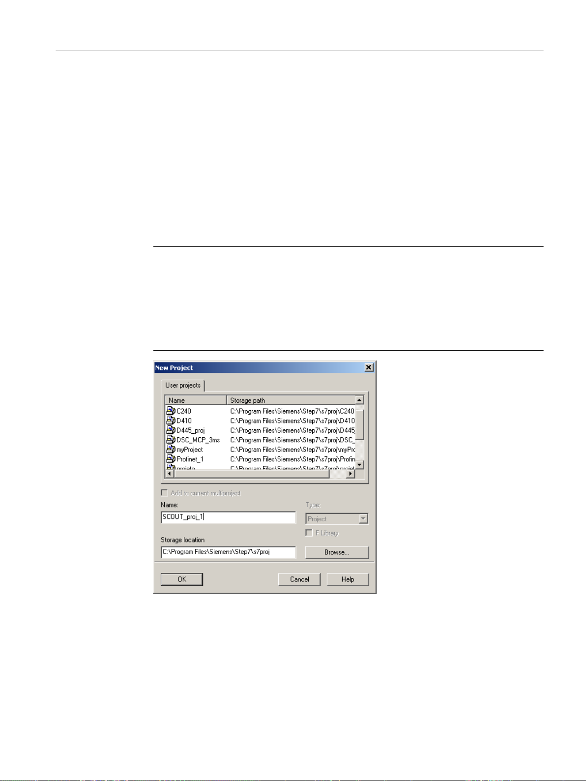
6.3.2 Creating a new project
To create a new project
1. Open SIMOTION SCOUT from the Start menu on the Windows desktop Start > All
Programs > Siemens Automation > SIMATIC > STEP 7 > SIMOTION SCOUT (Windows
7).
Or double-click the SIMOTION SCOUT icon on your PC desktop.
SIMOTION SCOUT starts the workbench and the online help
Getting Started SIMOTION SCOUT.
2. In the workbench menu bar, select Project > New.
The New Project window opens.
Note
SIMOTION SCOUT creates a directory with the selected name. All files relevant to the
project are stored in this directory.
Directory names and file names are shortened to 8 characters. If you assign longer names,
they are displayed in SIMOTION SCOUT. However, these names are only managed with
8 characters in the Explorer.
Configuring/parameterizing
6.3 Managing projects
Special characters may not be used.
Figure 6-1 Creating a new project
SIMOTION SCOUT
Configuration Manual, 11/2016 67
Page 68

Configuring/parameterizing
6.3 Managing projects
3. Enter the following data in the dialog window:
– Name:
Select a name for the project.
– Storage location (path):
The default storage location (path), where the new project is to be stored, is displayed
here.
4. Click OK to confirm.
The new project appears in the project navigator with an icon and its full name. The associated
tree is expanded.
Figure 6-2 Workbench with new project
SIMOTION SCOUT
68 Configuration Manual, 11/2016
Page 69

Configuring/parameterizing
6.3 Managing projects
The following entries are located beneath the project name in the project navigator:
● Insert SIMOTION device element. Double-click this icon to select the required SIMOTION
device, create and configure a new subnet and insert the new device in the HW Config
program.
Figure 6-3 Insert SIMOTION device
● Insert single drive unit element. Double-click this icon to insert and commission a
standalone drive (e.g. MM4 Basic). Although this drive cannot be linked to or configured in
the master system of the project using a PROFIBUS DP connection, it appears in the project
navigator within the project.
● Folder labeled LIBRARIES
● Folder labeled MONITORING
SIMOTION SCOUT
Configuration Manual, 11/2016 69
Page 70

Configuring/parameterizing
6.3 Managing projects
6.3.3 Open project
To open a project saved on the hard disk of the PC:
You can open projects that SIMOTION SCOUT has stored locally (e.g. on the hard disk).
1. Select the Project > Open menu.
2. In the User projects tab, select the desired project.
If the project you want is not stored according to the default path: Click Browse... and follow
the instructions on the screen.
3. Click OK to confirm.
If you want to open a project that was created in an older version, a message appears asking
whether the project should be converted to the newer version. This function is available since
SIMOTION SCOUT Version V3.1.
Note
The Save as... function saves all previously made changes with a new name (as of V4.4).
Figure 6-4 Opening a project stored on the hard disk
Note
The workbench displays one project at a time.
If you want to display two projects at the same time, e.g. in order to copy/paste parts of a
project, start SIMOTION SCOUT a second time.
SIMOTION SCOUT
70 Configuration Manual, 11/2016
Page 71

6.3.4 Saving and compiling
SIMOTION SCOUT distinguishes three commands in the main project menu that act differently
when saving or saving and compiling:
● Save
● Save and compile changes
● Save and recompile all
Note
The project must be saved and compiled first before the download. For the default setting of
SIMOTION SCOUT, these steps are performed automatically during the download.
Save
The project is saved to the hard disk. The changes are accepted into the project. No further
processes (such as compilation or consistency checking) are triggered for the project.
Configuring/parameterizing
6.3 Managing projects
Save and compile changes
On this command, the whole project is searched for changes. If a source is found which has
been changed or has no compilation results, this and any linked sources are compiled and
saved (e.g. during an FB call). Therefore only the changes are compiled. Use this command
when performing your day-to-day tasks within a SCOUT version.
Save and recompile all
All sources of the entire project are recompiled with this command.
The Save and recompile all command is suitable if you are entirely sure that all the old data
from older SCOUT versions has been removed and should be replaced with new compilation
results. The command incorporates the following steps:
● Project-wide deletion of all compilation results
● Recompilation of all objects
Use this command if you specifically want to convert a project from an earlier SCOUT version
to a later one. This involves accepting all the error correction and optimization elements in the
new SCOUT. However in this case, the compilation results in the SIMOTION SCOUT and
SIMOTION RT become inconsistent. The project navigator and object comparison feature then
display the objects as "inconsistent" in ONLINE mode. You can only debug the project if you
have loaded the entire project to the target system.
Note
The compilation results remain consistent provided there were no error messages and the
compiler has not been changed.
SIMOTION SCOUT
Configuration Manual, 11/2016 71
Page 72

Configuring/parameterizing
6.3 Managing projects
Note
Libraries are compiled only for the device versions in which they are used.
6.3.5 Performing a consistency check
Checking the project for consistency and compiling the project
Before you download the project to the target system, the program sources must be compiled
without error and the consistency ensured. In this process, I/O addresses or TO configurations
are checked, for example.
1. Select the Project > Save and compile all menu.
2. SIMOTION SCOUT compiles all the changed sources.
3. Select the Project > Check consistency menu.
SIMOTION SCOUT checks, for example, whether all technology objects have been configured
and that the source files have been compiled without errors.
To compile all programs automatically before a download and to check the consistency, the
Compile all programs before loading and Check consistency before loading checkboxes must
be activated via Options > Settings on the Download tab.
For further information, please refer to the online help for SIMOTION SCOUT.
6.3.6 Archiving and backing up projects on memory cards
Procedure
In SIMOTION SCOUT, you can back up your project to the memory card as a *.zip file.
Proceed as follows to archive the SIMOTION project on the memory card:
1. Open SIMOTION SCOUT and select the Project -> Archive -> Normal... menu command.
2. In the Archive dialog, select the SIMOTION project and save it to your drive (PG/PC).
3. Open the project.
4. Go online with SIMOTION.
SIMOTION SCOUT
72 Configuration Manual, 11/2016
Page 73

5. In the project navigator, select the SIMOTION device and execute the Target system ->
Load -> Save archived project on card ... -> Normal ... or Reduced ... menu command (see
below).
6. In the dialog that is displayed, select the project and click Open. This saves the project to
the CompactFlash Card as Project.zip in the directory USER\SIMOTION\HMI\PRJLOG.
Note
If you want to load the current project from the card, select the Target system > Copy
archived project from card to PG/PC... menu command.
Prerequisite is that you have backed up the project with Save archive project on card...
each time a change was made.
Reducing the project archive
If, for example, you want to send a project as an e-mail, the normal archived and zipped
archives are too large.
You can influence the archiving of projects with the Project > Archive > Reduced ... function.
Configuring/parameterizing
6.3 Managing projects
● Remove data from the archive to reduce the file size.
● Divide the archive into packets, so that you can create several ZIP files that are combined
again when dearchiving.
For further information, please refer to the online help for SIMOTION SCOUT.
Additional references
Detailed information on loading data to the target device can be found in the
SCOUT Basic Functions
Function Manual.
6.3.7 Exporting and importing a project in XML format
A log of the export or import is displayed in the XML export/import status display tab in the
detail view. The XML export log also contains a link to the exported file. Double-click this link
to view the exported project data in the Internet browser.
Note
Projects are exported and imported version-neutral. However, if a project has version-specific
properties, related errors may occur following import into another SCOUT version, e.g. when
compiling ST programs.
SIMOTION
SIMOTION SCOUT
Configuration Manual, 11/2016 73
Page 74

Configuring/parameterizing
6.3 Managing projects
Exporting project/objects in XML format
To export the entire project data in XML format:
1. Select Project > Save and export. The Export Project window with the XML export/import
status display tab opens.
2. Select a target directory by clicking the Browse button. If you do not change the path, the
export files are saved in the current project folder as standard. See also "Export of projects".
3. Click OK to confirm.
The files in the target directory are deleted and the export of the project data is started. On
completion of export, the successfully completed export and the target path are displayed
in the XML export/import status display tab of the detail view.
4. Click the link silhouetted in blue to obtain more precise information about the exported
project.
Importing an XML file
Select the file of the technology object / device in XML format to be imported to a new project.
As import file, always select the XML file which has the name of the technology object / device.
Normally the exported file is displayed in this field so that you only have to perform the following
steps when you want to import another file.
To select the import file:
1. Click Browse to the right of the text field. A window opens.
2. Select the XML file that is to be imported.
Only a technology object that is completely available can be imported. Always select the
XML file which has the name of the previously exported technology object as the import
file. If it is not possible to import the selected file, the import is aborted.
3. Click Open to confirm. The window closes and the source path is displayed.
Additional references
Please refer to the online help on this subject
6.3.8 Searching in the project
In the open project, you can search all the project data for variables or any text.
If you select a variable search, you can also search within the ST sources. All global and local
variables at the declaration and use points are recognized.
Open the dialog using Edit > Search in project... on the menu bar or by using the shortcut
Ctrl + Shift + F.
The results are displayed in the Search results tab of the detail view.
SIMOTION SCOUT
74 Configuration Manual, 11/2016
Page 75

Configuring/parameterizing
6.3 Managing projects
Figure 6-5 Searching in the project
Searching in CPU/Libraries only
If the "Search only in CPU/Library" checkbox is activated, a selection list of all the CPUs and
user-defined libraries in the project appears. You can select one to search in this CPU/Library
only.
For more information regarding this topic, see the online help.
Local search
You can search locally for a specific text in the various editors and the declaration tables. To
start searching locally, open the search function with the Ctrl+F shortcut key while the current
focus is on an editor (e.g. MCC) or the editor window for global and unit-global declarations
and connections.
The
SIMOTION MCC Motion Control Chart Programming and Operating Manual
contains
further information on local searches.
SIMOTION SCOUT
Configuration Manual, 11/2016 75
Page 76

Configuring/parameterizing
6.3 Managing projects
6.3.9 Replacing in the project
The Replace in project function is based on the Search in project function.
Open the dialog using Edit > Replace in project... on the menu bar or with the shortcut
Ctrl + Shift + G.
When you carry out a replacement, both the results found and the replacement term are
displayed in the "Search result" tab of the "detail view". The text can be edited again here.
Use the Replace button to replace all search results selected using the checkbox.
Boundary conditions:
● Only text can be entered.
● Replaced texts cannot be undone.
More information on this topic is available in:
● Online help.
Local replace
You can search locally for a specific text in the various editors and the declaration tables, and
replace this text with freely selected text. To start the local replacement process, select the Ctrl
+H shortcut key while the current focus is on an editor (e.g. the MCC editor) or the editor
window for global and unit-global declarations and connections.
6.3.10 Printing projects
You can print various parts of a project or view them in the print preview in order to, for example,
document settings, data, etc. The part to be printed depends on the element selected in the
project navigator or the window active in the working area.
● An element is selected in the project navigator or a window is active in the working area.
The data of the associated technology object, MCC chart, etc. is printed.
● The detail view is active. The data of the active tab of the detail view is printed.
● The project is selected in the project navigator. All data of the project (e.g. programs,
execution system, technology objects) is printed.
Note
If you select Print or Print preview in the Project menu, the print dialog or the print preview
is displayed immediately. If you select the context menu for Print or Print preview of the
selected element in the project navigator, a window is displayed in which you can activate
the components to be printed. If, for example, you only want to print certain parts of a
technology object, select Print in the context menu.
For further information, please refer to the online help for SIMOTION SCOUT.
SIMOTION SCOUT
76 Configuration Manual, 11/2016
Page 77

6.4 Configuring devices
6.4.1 Adding a SIMOTION device
You have created a project in SIMOTION SCOUT. The project navigator on the left of the
SIMOTION SCOUT workbench is open. To insert a device, double-click the Insert SIMOTION
device entry below the name of your project in the project navigator. The following dialog opens:
Configuring/parameterizing
6.4 Configuring devices
Figure 6-6 Insert SIMOTION device
Select the device platform you are working with at Device. The characteristics of the relevant
platform then appear under Device characteristic.
SIMOTION SCOUT
Configuration Manual, 11/2016 77
Page 78

Configuring/parameterizing
6.4 Configuring devices
At SIMOTION Version, select the firmware version of the device used.
Note
The selected firmware version must match the firmware version on the memory card of the
SIMOTION device. Otherwise, you will receive an error message when going online with the
device.
If the Open HW Config option is selected, the hardware configuration (Page 79) opens after
the device has been inserted. Click OK to confirm.
Once you have created a SIMOTION device in the project via the Insert SIMOTION device
element, the hardware configuration (HW Config) opens automatically.
In HW Config, you inform the SIMOTION system which hardware is present; for example:
● Type of the SIMOTION device
● Type of the I/O modules
● Type of the drives
In addition, you also specify which parameters the SIMOTION system should use, e.g.:
● Configuration of the SIMOTION device
● Configuration of the PROFIBUS/PROFINET
● Assignment of the hardware to PROFIBUS/PROFINET
The following sections explain how to use the HW Config tool:
● How to insert objects from the hardware catalog.
● How to edit objects.
● How to replace or delete objects.
6.4.1.1 Starting HW Config
HW Config can be started, e.g. to add a drive to the PROFIBUS.
To start HW Config:
● Double-click the appropriate SIMOTION device in the project navigator or
● Select the appropriate device in the project navigator and confirm your selection in the Open
HW configuration context menu or
● Highlight the appropriate device in the project navigator and click Edit > Open object in the
menu bar.
SIMOTION SCOUT
78 Configuration Manual, 11/2016
Page 79

6.4.1.2 The HW Config program
The HW Config program is displayed as follows:
● A hardware catalog window
● A working window that is split into two:
– In the upper half, you can see the rack or station frame with the CPU already inserted
automatically in slot 2 (example for C240).
Insert the objects from the hardware catalog and edit them here.
– In the lower half, you can see detailed information about the selected objects.
Configuring/parameterizing
6.4 Configuring devices
Figure 6-7 HW Config with opened hardware catalog and the CPU previously inserted in the
module
6.4.1.3 HW Config: Opening the hardware catalog
You can open the hardware catalog in the following ways:
● Select the Insert > Insert object menu.
● Select the View > Catalog menu.
For further information, see Section Inserting a drive (Page 88).
SIMOTION SCOUT
Configuration Manual, 11/2016 79
Page 80

Configuring/parameterizing
6.4 Configuring devices
6.4.1.4 SIMOTION devices in the hardware catalog
You can find the SIMOTION devices in the corresponding directories of the hardware catalog
in HW Config.
With SIMOTION D, the SINAMICS version is selected in addition to the SIMOTION version.
The SIMOTION version determines whether one or more SINAMICS versions are available.
Adding interfaces
After you have inserted the SIMOTION device, the dialog for configuring the interfaces opens
Note
With SIMOTION D, the PROFIBUS subnet PROFIBUS Integrated DP master system is created
and configured automatically. The user may neither configure nor select it!
Figure 6-8 Hardware configuration of a D4x5
Detailed information on the configuration of the SIMOTION device is contained in the
corresponding documentation for the SIMOTION devices.
6.4.2 Selecting technology packages
The technology packages (e.g. TP CAM, TP PATH, DCBlib) are available in various versions
for installation purposes.
SIMOTION SCOUT
80 Configuration Manual, 11/2016
Page 81

Configuring/parameterizing
6.4 Configuring devices
You can only use the functions of the technology objects selected if the technology objects
are available in the target system. You can select the technology packages and their product
versions (as well as the service packs and hotfix versions) for each SIMOTION device.
In the Select Technology Packages window, you can adopt a more selective approach when
choosing the technology packages you want to use. To open this window, right-click a
SIMOTION device in the project navigator. Then select the Select Technology Packages
command in the context menu.
Figure 6-9 Selecting technology packages
Note
Device diagnostics can provide information on which technology package product version has
been loaded to a CPU.
Loading technology packages to the target device
Technology packages are only loaded to the target device if no technology package has been
loaded so far. If a technology package version changes, the technology package must be
explicitly reloaded to the target device. Proceed as follows:
1. Select Project > Download to target system in SIMOTION SCOUT.
2. Click Additional CPU options in the Download to target system dialog.
SIMOTION SCOUT
Configuration Manual, 11/2016 81
Page 82

Configuring/parameterizing
6.4 Configuring devices
3. Select the option Replace product versions of the technology packages.
4. Click OK to confirm.
For further information, please refer to the online help for SIMOTION SCOUT.
6.4.3 Connecting to the target system
6.4.3.1 Installing the interface card
Installing the interface card in the PG/PC
Communication between a SIMOTION device and a PG/PC requires an interface card for
PROFIBUS or an Ethernet interface. PGs already have both, but PCs may need an interface
card to be installed.
The PG/PC is used for configuration, parameter assignment, programming, and testing.
● Install the interface card in the PG/PC according to the manufacturer's installation
instructions.
● Install the appropriate drivers on the PG/PC.
● Connect the interface card to the interface of the SIMOTION device indicated below using
a suitable cable.
Table 6-1 Interface assignment for SIMOTION devices
SIMOTION device Interface As supplied
SIMOTION C230‑2 / C240 X8 DP1
X9 DP2 / MPI
X7 (Ethernet) IP address: 169.254.11.22
SIMOTION C240 PN X8 DP1
X9 DP2 / MPI
X7 (Ethernet) IP address: 169.254.11.22
X11
(1 PROFINET interface with 3
ports)
SIMOTION P350 X101 DP1
X102 DP2 / MPI
Ethernet IP address: 169.254.11.22
PROFIBUS address 2, baud rate 1.5 Mbit/s
PROFIBUS address 2, baud rate 1.5 Mbit/s
Subnet: 255.255.0.0
PROFIBUS address 2, baud rate 1.5 Mbit/s
PROFIBUS address 2, baud rate 1.5 Mbit/s
Subnet: 255.255.0.0
Supplied without IP address and subnet
PROFIBUS address 2, baud rate 1.5 Mbit/s
PROFIBUS address 2, baud rate 1.5 Mbit/s
SIMOTION SCOUT
82 Configuration Manual, 11/2016
Page 83

Configuring/parameterizing
6.4 Configuring devices
SIMOTION device Interface As supplied
SIMOTION P320-4 X1 Onboard Ethernet 1 Access to/from Windows:
IP address: 169.254.11.21
Subnet: 255.255.0.0
Access to/from SIMOTION P Runtime:
IP address: 169.254.11.22
Subnet: 255.255.0.0
X3 PROFINET onboard interface
with 3 ports
SIMOTION D4x5 X126 DP1
X136 DP2 / MPI
X120 IE1/ OP
(Ethernet)
X130 IE2/ NET
(Ethernet)
With optionally inserted CBE30:
X1400 (one PROFINET interface
with 4 ports)
SIMOTION D4x5-2 DP X126 DP
X136 DP/MPI
X120 P1 PN/IE-OP
(Ethernet)
X127 P1 PN/IE
(Ethernet)
X130 P1 PN/IE-NET
(Ethernet)
SIMOTION D4x5-2 DP/PN X126 DP
X136 DP/MPI
X127 P1 PN/IE
(Ethernet)
X130 P1 PN/IE-NET
(Ethernet)
X150 P1-P3 PN
(1 PROFINET interface with
3 ports)
With the optional inserted
CBE30-2:
X1400 (1 PROFINET interface
with 4 ports)
SIMOTION D410 DP X21 DP PROFIBUS address 2, baud rate 1.5 Mbit/s
SIMOTlON D410 PN X200 and X201
(1 PROFINET interface with
2 ports)
SIMOTION D410‑2 DP X21 DP/MPI
X24 DP
X127 P1 PN/IE
(Ethernet)
Supplied without IP address and subnet
PROFIBUS address 2, baud rate 1.5 Mbit/s
PROFIBUS address 2, baud rate 1.5 Mbit/s
IP address: 192.168.214.1
Subnet: 255.255.255.0
IP address: 169.254.11.22
Subnet: 255.255.0.0
Supplied without IP address and subnet
PROFIBUS address 2, baud rate 1.5 Mbit/s
PROFIBUS address 2, baud rate 1.5 Mbit/s
Supplied without IP address
and subnet
IP address: 169.254.11.22
Subnet mask: 255.255.0.0
Supplied without IP address and subnet
PROFIBUS address 2, baud rate 1.5 Mbit/s
PROFIBUS address 2, baud rate 1.5 Mbit/s
IP address: 169.254.11.22
Subnet mask: 255.255.0.0
Supplied without IP address and subnet
Supplied without IP address and subnet
Supplied without IP address and subnet
Supplied without IP address and subnet
PROFIBUS address 2, baud rate 1.5 Mbit/s
PROFIBUS address 2, baud rate 1.5 Mbit/s
IP address: 169.254.11.22
Subnet mask: 255.255.0.0
SIMOTION SCOUT
Configuration Manual, 11/2016 83
Page 84

Configuring/parameterizing
6.4 Configuring devices
SIMOTION device Interface As supplied
SIMOTION D410‑2 DP/PN X21 DP/MPI PROFIBUS address 2, baud rate 1.5 Mbit/s
X127 P1 PN/IE
(Ethernet)
X150 P1, P2
(1 PROFINET interface with
2 ports)
IP address: 169.254.11.22
Subnet mask: 255.255.0.0
Supplied without IP address and subnet
6.4.3.2 Set PG/PC interface
Setting interfaces
Proceed as follows:
1. Start SIMOTION SCOUT.
2. Select the Options > Set PG/PC interface menu.
The Set PG/PC Interface window opens.
Figure 6-10 Set PG/PC interface (example)
3. Select the access point of the application.
SIMOTION SCOUT
84 Configuration Manual, 11/2016
Page 85

4. Click Select.
The Install/Remove Interfaces window opens.
Figure 6-11 Installing/uninstalling interfaces
5. Select the module to be installed.
6. Click Install.
Configuring/parameterizing
6.4 Configuring devices
7. Click Close to exit the dialog.
8. Confirm the settings by clicking OK.
Installing/uninstalling other interfaces
Proceed as follows to install or uninstall additional interfaces:
1. In the Set PG/PC Interface window, select S7ONLINE as the access point of the application.
2. Click Select at Add/remove interfaces.
3. In the left-hand field, select the interface that you want to install, and click Install.
Or select the interface that you want to uninstall in the right-hand field and click Uninstall.
4. Click Close.
5. Select the interface to be used in the Used interface parameterization field.
The list of the used interface parameterization will be taken from SIMATIC STEP 7.
With the PC Adapter (Auto) setting, the interface to which the PG/PC is connected is
examined. This function automatically determines the current parameterization of the
respective interface.
Detailed information on the individual interfaces of the SIMOTION devices can be found in
the relevant commissioning manuals.
6. Click Properties to parameterize the interface.
7. Click OK to confirm.
6.4.3.3 Specifying the access point
Selecting the access point
The addresses for a device to go online depend on the access point S7ONLINE or the
alternative access point DEVICE.
SIMOTION SCOUT
Configuration Manual, 11/2016 85
Page 86

Configuring/parameterizing
6.4 Configuring devices
Depending on the selected access point, you can go online via different interfaces.
Proceed as follows to select the access point:
1. Open the project.
2. Select the SIMOTION device in the project navigator.
3. Right-click and select Properties... in the context menu.
The Properties - [CPU] window opens.
4. Go to the Device / access point tab. You can select the access point and specify the
addresses.
5. Click OK to close the dialog.
6.4.3.4 Communication via PROFIBUS DP
PROFIBUS is a powerful, open, and robust bus system, which guarantees trouble-free
communication. The system is fully standardized, which enables trouble-free connection of
standardized components from a variety of manufacturers. Configuration, commissioning, and
troubleshooting can be carried out from any side. This results in user-defined communication
relationships that are very versatile, simple to implement, and easy to change.
The high-speed, cyclic exchange of data with field devices (distributed I/O) is carried out via
the PROFIBUS DP protocol. Expansion of the protocol to include isochronous mode also
integrates the drive components into communication via PROFIBUS DP. The individual
components can be connected via the integrated interfaces, connections, interface modules
or communications processors.
Important information on communication with PROFIBUS is contained in the following catalog:
SIMOTION, SINAMICS S120 and Motors for Production Machines, PM 21 Catalog
SIMOTION SCOUT
86 Configuration Manual, 11/2016
Page 87

Configuring/parameterizing
6.4 Configuring devices
The following PROFIBUS DP subnet applications are possible:
● PROFIBUS DP isochronous
Compatible extension to the standard PROFIBUS DP:
– Equidistance (constant synchronous bus cycle clock) enables synchronized time slices
for master/slave applications.
– Data exchange broadcast enables slave-to-slave communication.
Digital drives (e.g. SINAMICS, MICROMASTER 4xx, ...) can be connected via
PROFIBUS DP.
In order to be able to operate the SIMOTION device with two isochronous
PROFIBUS DP subnets, isochronous mode and the same bus cycle must be set. The cycle
clock of the subnet of the second PROFIBUS interface is synchronized to the cycle clock
of the subnet of the first PROFIBUS interface.
If the bus cycle does not agree, the second PROFIBUS interface of the SIMOTION device
will be operated as a PROFIBUS DP subnet.
● PROFIBUS DP (MPI)
Standard PROFIBUS DP with DP-V0 and optional DP-V1 or DP-V2 functionality.
– For the connection of distributed I/Os
– For the connection to a higher-level automation system
– For the connection of HMI devices
– For the connection to the SCOUT engineering system
6.4.3.5 Ethernet communication
SIMOTION devices can also be connected to a PG/PC via Industrial Ethernet. Industrial
Ethernet is a communication network with a transmission rate of 1 Gbit/s.
For additional information, refer to the Manual "SIMATIC NET Industrial Twisted Pair and Fiber
Optic Networks." See the
SIMOTION Documentation Overview
Examples for the use of Industrial Ethernet:
● For the connection of HMI devices
● For connection to the SCOUT engineering system
● For communication via UDP (User Datagram Protocol)
● TCP/IP
● IT DIAG
6.4.3.6 Communication via PROFINET
for the Article No.
SIMOTION devices can be connected to a PROFINET subnet via interface modules or the
onboard PROFINET interface. With PROFINET IO IRT/RT, IT services can be performed in
parallel to realtime communication via an Ethernet cable. PROFINET IO supports parallel
operation of:
● IRT (isochronous realtime Ethernet)
● RT (realtime Ethernet)
SIMOTION SCOUT
Configuration Manual, 11/2016 87
Page 88

Configuring/parameterizing
6.4 Configuring devices
● TCP/IP, UDP, http ... (standard Ethernet services)
● For mixed operation of IRT and RT it has to be observed that the IRT-compatible devices
must form an IRT domain, i.e. there must not be any non-IRT devices on the data
transmission link between the IRT devices.
Additional references
Please refer to the following documents on this subject
● SIMOTION D4x5 Commissioning and Hardware Installation Manual
● SIMOTION D4x5-2 Commissioning and Hardware Installation Manual
● SIMOTION D410 Commissioning Manual
● SIMOTION D410-2 Commissioning and Hardware Installation Manual
● SIMOTION P320-4 E / P320-4 S Commissioning and Hardware Installation Manual
● SIMOTION C Operating Instructions
● SIMOTION Communication System Manual
and the SIMOTION SCOUT online help.
6.4.4 Inserting a drive
6.4.4.1 Drives with SIMOTION
Note the following:
Drives must be differentiated between:
● Drives that are connected to PROFIBUS/PROFINET
● Drives that are connected directly to the SIMOTION device
SIMOTION SCOUT
88 Configuration Manual, 11/2016
Page 89

Configuring/parameterizing
6.4 Configuring devices
The following applies to drives connected to PROFIBUS/PROFINET:
● Only drives that meet the requirements of PROFIdrive profile V3.0 can be connected:
– SINAMICS
– MICROMASTER (PROFIBUS only)
– COMBIMASTER 411 (PROFIBUS only)
– MASTERDRIVES (MC, VC) (PROFIBUS only)
– SIMODRIVE 611U (PROFIBUS only)
– SIMODRIVE POSMO (CA, CD, SI) (PROFIBUS only)
– ADI4 (analog drive interface for 4 axes)
– IM 174 (interface module for 4 axes)
● These drives are taken into the hardware configuration.
● The drives of the SINAMICS and MICROMASTER drive families can be configured,
assigned parameters, and commissioned with SIMOTION SCOUT.
All analog drives can be connected via one of the four analog interfaces on the
SIMOTION C230‑2/C240 or via the ADI4 and IM174 PROFIBUS module.
● These drives are inserted into the project via the hardware configuration.
● The SIMOTION device requires only the actual values from the encoder at the input and
issues the setpoints at the analog output.
● The drives must be configured, assigned parameters, and commissioned directly on the
corresponding device.
With SIMOTION D, drives on SINAMICS Integrated are not inserted via the HW Config. For
more detailed information, see the
D Commissioning and Hardware Installation Manual.
6.4.4.2 Inserting a SINAMICS drive on PROFIBUS DP
Initial situation
● The SIMOTION device is created in SIMOTION SCOUT
● A PROFIBUS subnet has been configured, for example, as PROFIBUS DP isochronous
(by selecting Edit > Isochronous operation)
● The subnet interface is the master on this subnet of the SIMOTION device
Proceed as follows:
1. Open the PROFIBUS DP folder in the hardware catalog.
2. Open the SINAMICS subfolder.
SIMOTION SCOUT
Configuration Manual, 11/2016 89
Page 90

Configuring/parameterizing
6.4 Configuring devices
3. Use drag-and-drop to drag an entry to the isochronous PROFIBUS subnet of the
SIMOTION device.
4. Double-click the SINAMICS drive Properties to open them and set a cycle clock.
Figure 6-12 Inserting a SINAMICS drive
6.4.4.3 Inserting a SINAMICS drive on PROFINET IO
Initial situation
● The SIMOTION device is created in SIMOTION SCOUT
● A PROFINET IO system and an Ethernet subnet are configured
Proceed as follows:
1. Open the HW Config of the SIMOTION device.
2. Open the PROFINET IO / Drives / SINAMICS folder in the hardware catalog.
SIMOTION SCOUT
90 Configuration Manual, 11/2016
Page 91

Configuring/parameterizing
6.4 Configuring devices
3. Select the SINAMICS S120 CBE20 drive.
4. Use drag-and-drop to drag the drive to the PROFINET IO subnet of the SIMOTION device.
Figure 6-13 Inserting a SINAMICS drive with PROFINET
Configuration for PROFINET IRT
Information for the configuration of PROFINET IRT is contained in the Communications
System Manual, Inserting and Configuring SINAMICS S120 section, as well as at the FAQ SIMOTION & SINAMICS: Distributed synchronous operation and isochronous mode via
PROFINET IRT
6.4.4.4 Commissioning the drives
Drives that can be commissioned with SIMOTION SCOUT
You can use SIMOTION SCOUT to assign parameters to the following drives:
● SINAMICS
● MICROMASTER
● COMBIMASTER 411
SIMOTION SCOUT
Configuration Manual, 11/2016 91
Page 92

Configuring/parameterizing
6.4 Configuring devices
For all other drives or for third-party drives, the appropriate commissioning program for the
specific drive must be used. If required, you must commission these drives directly on the drive.
Table 6-2 Commissioning of various drives
Drive Connection Commissioning
SINAMICS S110, S120,
S150,
G110 CPM100, G120, G130,
G150, GM150
SINAMICS S120 PROFINET With SIMOTION SCOUT or
MICROMASTER 410 analog interface With SIMOTION SCOUT or
MICROMASTER
420/430/440
COMBIMASTER 411 PROFIBUS DP or
SIMODRIVE 611U PROFIBUS DP or analog
MASTERDRIVES MC, VC PROFIBUS DP or analog
SIMODRIVE POSMO
CA; CD, SI
Third-party drives Analog interface or
PROFIBUS DP or analog
interface
PROFIBUS DP or
analog interface
analog interface
interface
interface
PROFIBUS DP With SIMOCOM U or
PROFIBUS DP accord‐
ing to PROFIdrive profile
V3.02
With SIMOTION SCOUT or
STARTER
STARTER
DRIVE ES Basic or
STARTER
With SIMOTION SCOUT or
DRIVE ES Basic or
STARTER
With SIMOTION SCOUT or
DRIVE ES Basic or
STARTER
With SIMOCOM U or
DRIVE ES Basic
With SIMOVIS or
DRIVE ES Basic
DRIVE ES Basic
With commissioning tool supplied by the
manufacturer
Note
If the Drive-ES Basic commissioning program is installed, it can be called by SIMOTION
SCOUT in the project navigator via Commissioning.
6.4.4.5 SINAMICS S120 on SIMOTION
STARTER functionality in SIMOTION SCOUT
It is possible to parameterize drives directly with SIMOTION SCOUT. The following example
describes how to insert a SINAMICS drive in SIMOTION SCOUT.
SIMOTION SCOUT
92 Configuration Manual, 11/2016
Page 93

Requirements:
● SIMOTION SCOUT has been installed on the PG/PC
● A SIMOTION SCOUT has been created
Note
You can create the SINAMICS drive with PROFIBUS or PROFINET.
You must execute the following steps:
● Insert SIMOTION device
● Configure SINAMICS
Commissioning in SIMOTION SCOUT
1. Open the SIMOTION project in SIMOTION SCOUT.
2. Double-click Insert SIMOTION device.
Configuring/parameterizing
6.4 Configuring devices
3. Select a SIMOTION device.
4. Select the variant.
5. Click OK to confirm.
6. Select the PROFIBUS interface or Ethernet.
If you have selected Ethernet, select the interface parameterization of the PG/PC.
7. Click OK to confirm.
8. With SIMOTION C and P only: Insert a SINAMICS device (see Inserting a drive (Page 88)).
9. Select Station > Save and compile in the HW Config and then close HW Config.
10.Open the structure tree of the SIMOTION device in the project navigator.
11.Open the structure tree of the drive (SINAMICS or SINAMICS_Integrated) in the project
navigator.
12.Double-click Configure drive unit.
The Configuration - Option Module window opens.
13.Run through the drive wizard.
The STARTER functionality now starts in SIMOTION SCOUT.
The configuring of the SINAMICS Integrated drive for SIMOTION D is described in the
SIMOTION D Commissioning and Hardware Installation Manuals.
Note
You can insert a standalone drive (e.g. SINAMICS S120) with the "Insert single drive unit"
element in the project navigator. It is commissioned using wizards in the working area of the
workbench that contains the STARTER functionality.
SIMOTION SCOUT
Configuration Manual, 11/2016 93
Page 94

Configuring/parameterizing
6.4 Configuring devices
6.4.4.6 Configuring the infeed
Overview
The integrated SINAMICS control unit only starts the drive when the infeed is ready. The project
must therefore know the interface via which the drive receives the ready signal of the infeed.
Two cases must be distinguished here:
● Infeed with DRIVE‑CLiQ interface
If an infeed with DRIVE‑CLiQ connection has already been created, the ready signal of the
infeed (r0863.0) is automatically interconnected with "Infeed operation, p0864" of the drive
when drives are inserted (only applies to drives that are attached to the same drive unit as
the infeed).
Further information about the infeed with the DRIVE-CLiQ interface is contained in the
SIMOTION D Commissioning and Hardware Installation Manuals.
● Infeed without DRIVE‑CLiQ interface
If you are using an infeed without a DRIVE-CLiQ interface, e.g. a Smart Line Module, you
must wire the ready signal of the infeed via terminals. The following section describes the
procedure.
Configure the infeed without a DRIVE-CLiQ interface
Interconnecting the ready signal of the infeed
An infeed without DRIVE‑CLiQ interface provides the ready signal (p0863.0) via an output
terminal. In the project, you specify on which input (r0722) of SINAMICS Integrated the signal
is active. The drive supplied by the infeed uses the signal as a ready signal (p0864).
Note
A drive on SINAMICS Integrated of a SIMOTION D can only be moved if the infeed is ready.
Requirements
● You have configured a drive.
● SIMOTION SCOUT is in online mode.
SIMOTION SCOUT
94 Configuration Manual, 11/2016
Page 95

Procedure
Configuring/parameterizing
6.4 Configuring devices
In the next step, in order to wire the ready signal of the infeed (terminal "DO: Ready" of the
infeed) with the DI 0 of the D4x5-2, proceed as follows in case you have not already established
the interconnection during processing using the drive wizard:
1. Navigate in the project navigator to the Drives folder and double-click Configuration below
the drive.
Figure 6-14 Configuring a drive
2. Click in the working area on the Configure DDS button with the yellow background.
Figure 6-15 Configuring DDS
The drive wizard opens.
3. Click Next in the drive wizard until you reach the dialog Configuration -
SINAMICS_Integrated - BICO power unit.
4. In the input field p0864, select the digital input (e.g. DI 0) to which the ready signal of the
infeed is wired.
Figure 6-16 BICO interconnection
SIMOTION SCOUT
Configuration Manual, 11/2016 95
Page 96

Configuring/parameterizing
6.4 Configuring devices
5. Click Next. Run through all the other dialogs without change until the final Summary dialog.
6. Click Finish.
Thus, the configuration is finished.
6.4.4.7 Testing the drive with the drive control panel
Drive control panel
The drive control panel is used to control and monitor individual drives. With the drive control
panel, you can traverse drives and can:
● Test each part of the system individually before the drives are traversed in a coordinated
manner by means of a program.
● Test in a fault situation whether the individual drives can be traversed by the drive control
panel at all, or whether there are already problems here.
WARNING
Requirements
This software may be used only when the associated safety instructions are observed! The
non-observance can cause injury to persons or damage to material!
The function is released exclusively for commissioning, diagnostic and service purposes. The
function should generally only be used by authorized technicians. The safety shutdowns from
the higher-level control have no effect.
The Stop with preconfigured braking ramp function is not guaranteed in all operating states.
Therefore, there must be an EMERGENCY STOP circuit in the hardware. The appropriate
measures must be taken by the user.
● You have created and fully configured a drive in the project.
● You have stored and compiled the project. The project is consistent.
● SIMOTION SCOUT is in online mode.
● The project with the drive parameterization has been loaded to the target system.
SIMOTION SCOUT
96 Configuration Manual, 11/2016
Page 97

Opening the drive control panel
To open the drive control panel, proceed as follows:
1. In the project navigator, navigate to the drive unit and open the Drives folder.
2. Open the Commissioning entry and double-click Control panel.
The drive control panel opens in the detail view.
Configuring/parameterizing
6.4 Configuring devices
Figure 6-17 Drive control panel
Using the drive control panel
Assuming control priority
To assume control priority, proceed as follows:
1. Click the
n=.
2. Click the button to show the diagnostics area in order to display and evaluate the defined
parameters.
You can determine the status of the required enables by clicking the Diagnostics button.
3. In the selection list, select the drive that you want to control or monitor using the PG/PC,
SINAMICS_Integrated_1 - SERVO_03 in the example.
4. Specify the parameters that you want to display in the selection lists on the bottom right-
hand side of the diagnostics area. The values are displayed below.
button to show the control area in order to test the motor speed specified at
SIMOTION SCOUT
Configuration Manual, 11/2016 97
Page 98

Configuring/parameterizing
6.4 Configuring devices
5. Select Assume control priority to establish the connection to the PG/PC. The Assume
control priority dialog is displayed.
Figure 6-18 Assuming control priority
6. Consider the following infeed options for the type of connection you are using.
– If you are using an infeed with a DRIVE-CLiQ interface, select the infeed for which the
control priority is to be assumed at Infeed in the Assume control priority dialog.
Activate the Infeed option if the infeed control priority is to be assumed and activated.
– If you are using an infeed without a DRIVE-CLiQ interface, you must interconnect the
Infeed operation signal (drive parameter p0864) yourself. In this case, the dialog does
not contain any fields for selecting infeed.
– If the signal of the Closed-loop control operation infeed is already BICO interconnected
with the drive, the infeed is specified permanently. No selection is possible in the dialog,
the fields are grayed out.
7. Observe the safety regulations and confirm with Accept.
The PG/PC has the control priority; the button caption has changed to Return control priority.
Note
You can also stop the drive at any time by pressing the SPACEBAR.
SIMOTION SCOUT
98 Configuration Manual, 11/2016
Page 99

Configuring/parameterizing
6.4 Configuring devices
Activating the infeed
To switch on the infeed, proceed as follows:
1. Click the button for more information.
Activating enables
To activate the enables, proceed as follows:
1. Activate the Enables option to enable the drive.
The ON and OFF buttons and are activated and the enable states are indicated by
the LEDs.
Click the "Diagnostics" button to show any missing enables.
Testing the drive
To test the drive, proceed as follows:
1. Specify a speed setpoint in the n= field.
2. Use the slider to set the current speed setpoint in relation to the maximum speed
setpoint (100%).
Result
3. Click the green switch to start the drive.
Or click the switch to control the drive in jog mode. The motion continues as long as
you keep the switch pressed.
In the diagnostics area you can monitor the set speed/torque as well as the actual speed/
torque.
Exiting the drive control panel
To exit the drive control panel, proceed as follows:
1. Click the red button to stop the drive.
2. Deactivate the Enables option.
The LEDs are grayed out.
3. Deactivate the infeed. To do this, click Infeed on/off.
4. Click the Return control priority button to return the control priority of the control panel.
5. On the menu bar, select Project > Disconnect from target system to switch to offline mode.
The drive can be operated. The drive configuration is complete.
SIMOTION SCOUT
Configuration Manual, 11/2016 99
Page 100

Configuring/parameterizing
6.5 Creating and testing an axis
6.5 Creating and testing an axis
6.5.1 TO axis technology object
Note
You create the technology object (TO) axis in SIMOTION SCOUT TIA.
You can create the axis both in offline and online mode.
Technology objects represent the respective real objects, e.g. a position axis, in the controller.
The technology object axis offers the user a technological view of the drive and the encoder
(actuator and sensor) and provides technological functions, such as communication with the
drive, actual value processing, position control and positioning functionality. It executes control
and motion commands and indicates states and actual values.
Requirements
Axis technologies
If you want to insert a real axis, you require a functional drive.
If you want to insert a virtual axis, you do not require a functional drive.
Note
Virtual axis
All axis types can also be virtual axes, i.e. they do not control real drives but are used as
auxiliary axes, e.g. as a leading axis for several following axes (line shaft).
You can use the following axis technologies:
● Speed-controlled axis
Motion control is performed using a speed specification without position control.
● Positioning axis
Motions are position-controlled.
● Synchronous axis
The synchronous axis creates a grouping of the following axis and synchronous object.
● Path axis
The path axis type can be interconnected with a path object.
The path object can be used to calculate and traverse a linear, circular or polynomial path
in the 2D/3D coordinate system for at least two path axes and up to three path axes.
SIMOTION SCOUT
100 Configuration Manual, 11/2016
 Loading...