

Siemens SIMOTION Series, SIMOTION P320-4 S, SIMOTION P320-4 E Commissioning And Hardware Installation Manual

SIMOTION
SIMOTION P320-4 E / P320-4 S
Valid as of version V4.5
Preface
Commissioning and Hardware Installation Manual
Safety notes
Industrial security
Description
Use planning
Mounting
Connection
Power on and software
installation
1
2
3
4
5
6
7
Operator Control (hardware)
Parameter assignment/
addressing
Commissioning (software)
Service and maintenance
Alarm, error and system
messages
Troubleshooting/FAQs
Standards and approvals
8
9
10
11
12
13
A
11/2016
ESD guidelines
List of abbreviations
B
C
Legal information
Warning notice system
This manual contains notices you have to observe in order to ensure your personal safety, as well as to prevent
damage to property. The notices referring to your personal safety are highlighted in the manual by a safety alert
symbol, notices referring only to property damage have no safety alert symbol. These notices shown below are
graded according to the degree of danger.
DANGER
indicates that death or severe personal injury will result if proper precautions are not taken.
WARNING
indicates that death or severe personal injury may result if proper precautions are not taken.
CAUTION
indicates that minor personal injury can result if proper precautions are not taken.
NOTICE
indicates that property damage can result if proper precautions are not taken.
If more than one degree of danger is present, the warning notice representing the highest degree of danger will be
used. A notice warning of injury to persons with a safety alert symbol may also include a warning relating to property
damage.
Qualified Personnel
The product/system described in this documentation may be operated only by personnel qualified for the specific
task in accordance with the relevant documentation, in particular its warning notices and safety instructions. Qualified
personnel are those who, based on their training and experience, are capable of identifying risks and avoiding
potential hazards when working with these products/systems.
Proper use of Siemens products
Note the following:
WARNING
Siemens products may only be used for the applications described in the catalog and in the relevant technical
documentation. If products and components from other manufacturers are used, these must be recommended or
approved by Siemens. Proper transport, storage, installation, assembly, commissioning, operation and
maintenance are required to ensure that the products operate safely and without any problems. The permissible
ambient conditions must be complied with. The information in the relevant documentation must be observed.
Trademarks
All names identified by ® are registered trademarks of Siemens AG. The remaining trademarks in this publication
may be trademarks whose use by third parties for their own purposes could violate the rights of the owner.
Disclaimer of Liability
We have reviewed the contents of this publication to ensure consistency with the hardware and software described.
Since variance cannot be precluded entirely, we cannot guarantee full consistency. However, the information in
this publication is reviewed regularly and any necessary corrections are included in subsequent editions.
Siemens AG
Division Digital Factory
Postfach 48 48
90026 NÜRNBERG
GERMANY
Ⓟ 10/2016 Subject to change
Copyright © Siemens AG 2016.
All rights reserved

Preface
Preface
References
This document is part of the SIMOTION P documentation package.
This documentation describes the SIMOTION P320‑4 hardware platform which can be
delivered in the SIMOTION P320-4 E and SIMOTION P320-4 S hardware versions:
● SIMOTION P320‑4 E with the Windows Embedded Standard 7 32-bit operating system and
real-time expansion for SIMOTION.
Successor to SIMOTION P320-3.
● SIMOTION P320‑4 S with the Windows 7 Ultimate 32-bit operating system and real-time
expansion for SIMOTION.
Successor to SIMOTION P350-3.
The following documents contain the descriptions for the SIMOTION P hardware platform:
● SIMOTION P320-4 E / P320-4 S, Manual, Edition 11/2016
● SIMOTION P320-4 E / P320-4 S, Commissioning and Hardware Installation Manual, Edition
11/2016
Validity range
This Commissioning and Hardware Installation Manual is valid for the SIMOTION P320-4 E
and SIMOTION P320-4 S devices as of product level SIMOTION V4.5.
Standards
The SIMOTION system has been developed in accordance with ISO 9001 quality guidelines.
Sections in this documentation
The following sections describe the purpose and the use of this documentation:
● Safety instructions
This section contains fundamental safety instructions for SIMOTION and specific safety
instructions for the SIMOTION P320-4.
● Industrial Security
You can find important information on industrial security here. What is industrial security?
Which specific measures can be taken to protect your system from threats.
● Description
System overview and product description for the SIMOTION P320-4.
The communication versions are displayed.
SIMOTION P320-4 E / P320-4 S
Commissioning and Hardware Installation Manual, 11/2016 3

Preface
● Application planning
Points to note in advance:
Upon delivery, the permitted installation positions, environmental and ambient conditions
and electromagnetic compatibility.
You will find this information in the manual SIMOTION P320-4 E / P320-4 S.
● Installation
Description of the installation, mounting and assembly of the SIMOTION P320-4.
● Connection
This section describes the requirements for connecting and the connection overview for
the SIMOTION P320-4, and information on the connection of PROFINET, PROFIBUS and
Ethernet.
● Power on and software installation
Information on the first power-up of the SIMOTION P320-4 and additional software for HMI.
● Operation (hardware)
Detailed description of the SIMOTION P State application.
● Parameter assignment / addressing
This section contains the requirements for parameter assignment / addressing and an
overview of the factory settings.
One section describes the SIMOTION P Control Manager.
Communication with Ethernet and PC internal is described.
References are supplied for the PROFINET and PROFIBUS communication.
● Commissioning (software)
This section contains information, notes and requirements for the commissioning and a
recommended sequence for the first commissioning of the SIMOTION P320-4.
The topics data backup, data storage concept and SIMOTION P general reset are
described.
● Service and maintenance
Information on the recording of diagnostics data, restoring factory settings, installing and
removing the backup battery.
Description of special power-up situations.
● Alarm, fault, and system messages
Information on diagnostics via LED displays.
Description of possible alarm and fault messages.
● Troubleshooting/FAQs
List of possible errors and their remedies.
● Appendix
The appendices contain information on standards and approvals, on the ESD guideline as
well as a list of abbreviations.
● Index
Alphabetical directory for locating information.
SIMOTION Documentation
An overview of the SIMOTION documentation can be found in the SIMOTION Documentation
Overview document.
SIMOTION P320-4 E / P320-4 S
4 Commissioning and Hardware Installation Manual, 11/2016

This documentation is included as electronic documentation in the scope of delivery of
SIMOTION SCOUT. It comprises ten documentation packages.
The following documentation packages are available for SIMOTION V4.5:
● SIMOTION Engineering System Handling
● SIMOTION System and Function Descriptions
● SIMOTION Service and Diagnostics
● SIMOTION IT
● SIMOTION Programming
● SIMOTION Programming - References
● SIMOTION C
● SIMOTION P
● SIMOTION D
● SIMOTION Supplementary Documentation
Preface
Hotline and Internet addresses
SIMOTION at a glance
We have compiled an overview page from our range of information about SIMOTION with the
most important information on frequently asked topics - which can be opened with only one
click.
Whether beginner or experienced SIMOTION user – the most important downloads, manuals,
tutorials, FAQs, application examples, etc. can be found at
https://support.industry.siemens.com/cs/ww/en/view/109480700
Additional information
Click the following link to find information on the following topics:
● Documentation overview
● Additional links to download documents
● Using documentation online (find and search manuals/information)
https://support.industry.siemens.com/cs/ww/en/view/109479653
My Documentation Manager
Click the following link for information on how to compile documentation individually on the
basis of Siemens content and how to adapt it for the purpose of your own machine
documentation:
https://support.industry.siemens.com/My/ww/en/documentation
SIMOTION P320-4 E / P320-4 S
Commissioning and Hardware Installation Manual, 11/2016 5

Preface
Training
FAQs
Technical support
Click the following link for information on SITRAIN - Siemens training courses for automation
products, systems and solutions:
http://www.siemens.com/sitrain
Frequently Asked Questions can be found in SIMOTION Utilities & Applications, which are
included in the scope of delivery of SIMOTION SCOUT, and in the Service&Support pages in
Product Support:
https://support.industry.siemens.com/cs/de/en/ps/14505/faq
Country-specific telephone numbers for technical support are provided on the Internet under
Contact:
https://support.industry.siemens.com/cs/ww/en/sc/2090
SIMOTION P320-4 E / P320-4 S
6 Commissioning and Hardware Installation Manual, 11/2016

Table of contents
Preface.........................................................................................................................................................3
1 Safety notes................................................................................................................................................13
1.1 Fundamental safety instructions............................................................................................13
1.1.1 General safety instructions.....................................................................................................13
1.1.2 Safety instructions for electromagnetic fields (EMF)..............................................................16
1.1.3 Handling electrostatic sensitive devices (ESD)......................................................................16
1.1.4 Industrial security...................................................................................................................17
1.1.5 Danger to life due to software manipulation when using removable storage media..............18
1.1.6 Residual risks of power drive systems...................................................................................18
1.2 Specific safety instructions for SIMOTION P320-4................................................................19
1.2.1 General safety instructions for the SIMOTION P320-4..........................................................19
1.2.2 Notes on use..........................................................................................................................22
2 Industrial security........................................................................................................................................23
2.1 Security concept for SIMOTION P320-4................................................................................23
2.1.1 Security..................................................................................................................................23
2.2 Why is industrial security so important?.................................................................................25
2.2.1 Trends in the IT sector...........................................................................................................26
2.2.2 Possible corporate security holes..........................................................................................26
2.3 General security measures....................................................................................................27
2.3.1 Overview................................................................................................................................27
2.3.2 Plant security..........................................................................................................................29
2.3.2.1 Physical protection of critical production areas......................................................................29
2.3.3 Network security.....................................................................................................................30
2.3.3.1 Network segmentation...........................................................................................................30
2.3.4 System integrity......................................................................................................................33
2.3.4.1 System hardening..................................................................................................................33
2.4 Product-specific measures.....................................................................................................35
2.4.1 Virus scanners, Windows security patches, SIMOTION P.....................................................35
2.4.2 Changing the Windows user password..................................................................................36
2.4.3 Changing the AutoLogin.........................................................................................................40
2.4.3.1 SIMOTION P AutoLogin.........................................................................................................40
2.4.4 Deactivating the remote desktop connection.........................................................................47
3 Description..................................................................................................................................................51
3.1 System overview....................................................................................................................51
3.2 SIMOTION P320-4 product description.................................................................................52
3.2.1 SIMOTION P320-4 overview..................................................................................................52
3.2.2 Features.................................................................................................................................53
3.2.3 SIMOTION P320-4 (hardware) structure...............................................................................55
3.2.4 Interfaces and operating elements.........................................................................................56
3.2.5 SIMOTION P Runtime (software) structure............................................................................56
3.2.6 Components...........................................................................................................................57
SIMOTION P320-4 E / P320-4 S
Commissioning and Hardware Installation Manual, 11/2016 7

Table of contents
3.3 HMI and SIMOTION SCOUT.................................................................................................59
3.3.1 HMI and SIMOTION SCOUT Overview.................................................................................59
3.3.2 Local HMI or ES on SIMOTION P320-4.................................................................................60
3.3.2.1 Setting up a network bridge - MAC bridge miniport...............................................................61
3.3.3 HMI or ES via PROFINET......................................................................................................72
3.3.4 HMI or ES via Ethernet..........................................................................................................73
3.3.5 HMI or ES via IsoPROFIBUS (optional).................................................................................75
4 Use planning...............................................................................................................................................77
5 Mounting.....................................................................................................................................................79
5.1 Installation overview...............................................................................................................79
5.2 Headless operation................................................................................................................79
5.2.1 SIMOTION P320-4 - Headless operation...............................................................................79
5.2.2 Deactivating the remote desktop connection.........................................................................80
5.3 Decentralized structure..........................................................................................................82
5.4 Important information about installation.................................................................................82
5.5 Withdrawing/inserting the CFast card ...................................................................................83
5.5.1 Automatic restart for SIMOTION P Runtime..........................................................................86
5.6 Installing the SIMOTION P320-4 in the control cabinet.........................................................87
5.6.1 Notes on installation...............................................................................................................87
5.6.2 Standard rail mounting...........................................................................................................88
5.6.3 Vertical mounting...................................................................................................................91
5.7 SIMOTION P AutoLogin.........................................................................................................91
6 Connection.................................................................................................................................................99
6.1 Connection requirements.......................................................................................................99
6.2 Overview of connections......................................................................................................100
6.3 Connecting PROFINET........................................................................................................101
6.3.1 PROFINET onboard.............................................................................................................101
6.3.2 Connection...........................................................................................................................102
6.4 Mounting a strain relief.........................................................................................................103
6.5 Connecting PROFIBUS........................................................................................................104
6.5.1 Requirement.........................................................................................................................104
6.5.2 SYNC I/O connecting cable / Plugging in the IsoPROFIBUS board....................................105
6.5.3 Connecting the IsoPROFIBUS board...................................................................................107
6.5.4 IsoPROFIBUS board and PROFIBUS DP...........................................................................110
6.5.5 Connecting the bus connectors for the X101 and X102 interfaces (IsoPROFIBUS)...........110
6.5.6 PROFIBUS cable.................................................................................................................111
6.6 Connecting Ethernet............................................................................................................112
6.7 Connecting the keyboard and mouse..................................................................................113
6.8 Connecting the power supply...............................................................................................113
6.8.1 Safety rules..........................................................................................................................113
6.8.2 Standards and Regulations..................................................................................................114
6.8.3 Connecting the power supply...............................................................................................114
6.8.4 Protective conductor connection and potential equalization ...............................................115
SIMOTION P320-4 E / P320-4 S
8 Commissioning and Hardware Installation Manual, 11/2016

Table of contents
7 Power on and software installation...........................................................................................................117
7.1 Power-up..............................................................................................................................117
7.2 Additional software for HMI..................................................................................................118
7.3 Customer-specific software..................................................................................................118
8 Operator Control (hardware)....................................................................................................................119
8.1 SIMOTION P state application.............................................................................................119
8.1.1 SIMOTION P State application overview.............................................................................119
8.1.2 LED display..........................................................................................................................120
8.1.3 Mode selector.......................................................................................................................121
8.1.4 Current operating status.......................................................................................................122
8.1.5 Function elements................................................................................................................122
8.1.6 SIMOTION P State - menus.................................................................................................123
9 Parameter assignment/addressing...........................................................................................................127
9.1 Parameter assignment / addressing requirements..............................................................127
9.2 Factory settings....................................................................................................................127
9.2.1 Factory settings overview.....................................................................................................127
9.2.2 Ethernet - TCP/IP local........................................................................................................127
9.3 SIMOTION P control manager.............................................................................................128
9.3.1 Requirement.........................................................................................................................128
9.3.2 SIMOTION P Control Manager overview.............................................................................128
9.3.3 Calling SIMOTION P Control Manager from the control panel............................................128
9.3.4 Administration tab................................................................................................................129
9.3.4.1 Start SIMOTION P...............................................................................................................131
9.3.4.2 Automatic Restart By Plug-In External Memory Card..........................................................132
9.3.4.3 Runtime Network Connections.............................................................................................133
9.3.5 License tab...........................................................................................................................135
9.4 Local communication via PC internal...................................................................................137
9.4.1 Local communication (PC-internal) overview.......................................................................137
9.4.2 Checking the PC-internal settings........................................................................................137
9.4.3 Station Configurator.............................................................................................................138
9.5 Ethernet communication......................................................................................................140
9.5.1 Ethernet communication overview.......................................................................................140
9.5.2 Ethernet interface.................................................................................................................141
9.5.3 Default IP addresses for Windows and SIMOTION P Runtime...........................................143
9.5.4 Communication via an Ethernet interface............................................................................143
9.5.5 Establishing the active flag for an external PG/PC..............................................................147
9.6 PROFINET communication..................................................................................................148
9.6.1 Documentation.....................................................................................................................148
9.7 PROFIBUS communication..................................................................................................148
9.7.1 Documentation.....................................................................................................................148
9.8 Project download..................................................................................................................149
9.9 Battery monitoring................................................................................................................151
SIMOTION P320-4 E / P320-4 S
Commissioning and Hardware Installation Manual, 11/2016 9

Table of contents
10 Commissioning (software)........................................................................................................................153
10.1 Note before commissioning..................................................................................................153
10.2 Basic commissioning - initial startup....................................................................................153
10.3 Commissioning requirements...............................................................................................153
10.4 Notes on commissioning......................................................................................................154
10.5 Recommended order for first commissioning.......................................................................154
10.6 Data backup.........................................................................................................................155
10.6.1 Memory media.....................................................................................................................155
10.6.2 SIMATIC data backup..........................................................................................................156
10.6.3 Restore DVD........................................................................................................................156
10.7 Power-up of the SIMOTION P Kernel..................................................................................157
10.8 Data storage concept...........................................................................................................157
10.8.1 Data storage concept overview............................................................................................157
10.8.2 Memory model.....................................................................................................................160
10.8.3 Project update......................................................................................................................160
10.8.3.1 Overview..............................................................................................................................160
10.8.3.2 SIMOTION Project Download online....................................................................................161
10.8.3.3 SIMOTION SCOUT - download of the project data (file structure)......................................161
10.8.3.4 SIMOTION SCOUT - download of the project data with SIMOTION IT (ZIP file)................162
10.8.3.5 Backing up and restoring project data (file structure)...........................................................164
10.8.4 Single backups.....................................................................................................................165
10.8.4.1 Overview..............................................................................................................................165
10.8.4.2 Back up/restore SRAM.........................................................................................................165
10.8.4.3 Backing up non-volatile SIMOTION data (retain data).........................................................166
10.8.4.4 Restoring non-volatile SIMOTION data (retain data)...........................................................167
10.8.4.5 Save unit variables and global device variables..................................................................168
10.8.5 Defined states......................................................................................................................169
10.8.5.1 Overview..............................................................................................................................169
10.8.5.2 Restore the factory setting using SIMOTION P State..........................................................169
10.8.5.3 Overall reset using SIMOTION P State - operating mode switch setting MRES.................170
10.8.5.4 Delete SRAM via SIMOTION P State - button Restart (Del. SRAM)...................................171
10.9 SIMOTION P overall reset...................................................................................................172
10.9.1 SIMOTION P overall reset overview....................................................................................172
10.9.2 Overall reset using the mode selector (on screen)..............................................................174
10.10 Deleting user data on the CFast card..................................................................................177
10.11 Switching off.........................................................................................................................178
11 Service and maintenance.........................................................................................................................181
11.1 Recording diagnostic data....................................................................................................181
11.2 Restoring factory settings.....................................................................................................182
11.2.1 Overview of restoring the factory settings............................................................................182
11.2.2 Resetting the SIMOTION P320-4 to the delivery status.......................................................182
11.2.3 Reset SIMOTION P320-4 to the initial state........................................................................183
11.3 Upgrading runtime and firmware..........................................................................................184
11.4 Installing/removing the back-up battery of the SIMOTION P320-4......................................185
SIMOTION P320-4 E / P320-4 S
10 Commissioning and Hardware Installation Manual, 11/2016

Table of contents
11.4.1 Preventive maintenance.......................................................................................................185
11.4.2 Replacing the backup battery...............................................................................................185
11.5 Special power-up situations.................................................................................................189
11.5.1 Special startup situations overview......................................................................................189
11.5.2 Non-volatile data and SRAM handling.................................................................................189
11.5.3 After new installation / update of the SIMOTION P Kernel..................................................191
11.5.4 After restoring a backup copy..............................................................................................191
11.5.5 After a power failure/POWER FAIL......................................................................................192
12 Alarm, error and system messages..........................................................................................................193
12.1 Diagnosis using the LEDs....................................................................................................193
12.2 Temperature alarm...............................................................................................................196
12.3 Battery alarm........................................................................................................................197
12.4 Power failure / POWER FAIL...............................................................................................197
12.5 PROFINET bus error occurs................................................................................................199
12.6 Under-licensing....................................................................................................................200
12.7 Boot error messages............................................................................................................200
13 Troubleshooting/FAQs..............................................................................................................................201
13.1 Error correction....................................................................................................................201
13.2 Hotplug Enabled BIOS settings............................................................................................203
A Standards and approvals..........................................................................................................................209
A.1 General rules........................................................................................................................209
B ESD guidelines.........................................................................................................................................211
B.1 ESD definition......................................................................................................................211
B.2 Electrostatic charging of individuals.....................................................................................211
B.3 Basic measures for protection against discharge of static electricity...................................212
C List of abbreviations..................................................................................................................................213
C.1 Commissioning Manual, Abbreviations ...............................................................................213
Index.........................................................................................................................................................215
SIMOTION P320-4 E / P320-4 S
Commissioning and Hardware Installation Manual, 11/2016 11

Table of contents
SIMOTION P320-4 E / P320-4 S
12 Commissioning and Hardware Installation Manual, 11/2016
Safety notes
1.1 Fundamental safety instructions
1.1.1 General safety instructions
DANGER
Danger to life due to live parts and other energy sources
Death or serious injury can result when live parts are touched.
● Only work on electrical devices when you are qualified for this job.
● Always observe the country-specific safety rules.
Generally, six steps apply when establishing safety:
1. Prepare for shutdown and notify all those who will be affected by the procedure.
2. Disconnect the machine from the supply.
– Switch off the machine.
– Wait until the discharge time specified on the warning labels has elapsed.
– Check that it really is in a no-voltage condition, from phase conductor to phase
conductor and phase conductor to protective conductor.
– Check whether the existing auxiliary supply circuits are de-energized.
– Ensure that the motors cannot move.
3. Identify all other dangerous energy sources, e.g. compressed air, hydraulic systems, or
water.
4. Isolate or neutralize all hazardous energy sources by closing switches, grounding or shortcircuiting or closing valves, for example.
5. Secure the energy sources against switching on again.
6. Ensure that the correct machine is completely interlocked.
1
After you have completed the work, restore the operational readiness in the inverse sequence.
WARNING
Danger to life from hazardous voltage when connecting an unsuitable power supply
Touching live components can result in death or severe injury.
● Only use power supplies that provide SELV (Safety Extra Low Voltage) or PELV
(Protective Extra Low Voltage) output voltages for all connections and terminals of the
electronics modules.
SIMOTION P320-4 E / P320-4 S
Commissioning and Hardware Installation Manual, 11/2016 13
Safety notes
1.1 Fundamental safety instructions
WARNING
Danger to life from touching live parts on damaged devices
Improper handling of devices can result in damage.
For damaged devices, hazardous voltages can be present at the enclosure or at exposed
components; if touched, this can result in death or severe injury.
● Observe the limit values specified in the technical specifications during transport, storage,
and operation.
● Do not use damaged devices.
WARNING
Danger to life through electric shock due to unconnected cable shields
Hazardous touch voltages can occur through capacitive cross-coupling due to unconnected
cable shields.
● As a minimum, connect cable shields and the cores of power cables that are not used
(e.g. brake cores) at one end at the grounded housing potential.
WARNING
Danger to life due to electric shock when not grounded
For missing or incorrectly implemented protective conductor connection for devices with
protection class I, high voltages can be present at open, exposed parts, which when touched,
can result in death or severe injury.
● Ground the device in compliance with the applicable regulations.
WARNING
Danger to life due to fire spreading if housing is inadequate
Fire and smoke development can cause severe personal injury or material damage.
● Install devices without a protective housing in a metal control cabinet (or protect the device
by another equivalent measure) in such a way that contact with fire inside and outside the
device is prevented.
● Ensure that smoke can only escape via controlled and monitored paths.
SIMOTION P320-4 E / P320-4 S
14 Commissioning and Hardware Installation Manual, 11/2016

Safety notes
1.1 Fundamental safety instructions
WARNING
Danger to life from unexpected movement of machines when using mobile wireless devices
or mobile phones
Using mobile radios or mobile phones with a transmit power > 1 W closer than approx. 2 m
to the components may cause the devices to malfunction, influence the functional safety of
machines therefore putting people at risk or causing material damage.
● Switch off wireless devices or mobile phones in the immediate vicinity of the components.
WARNING
Danger to life due to fire if overheating occurs because of insufficient ventilation clearances
Inadequate ventilation clearances can cause overheating of components followed by fire and
smoke development. This can cause death or serious injury. This can also result in increased
downtime and reduced service life for devices/systems.
● Ensure compliance with the specified minimum clearance as ventilation clearance for the
respective component.
WARNING
Danger of an accident occurring due to missing or illegible warning labels
Missing or illegible warning labels can result in accidents involving death or serious injury.
● Check that the warning labels are complete based on the documentation.
● Attach any missing warning labels to the components, in the national language if
necessary.
● Replace illegible warning labels.
WARNING
Danger to life when safety functions are inactive
Safety functions that are inactive or that have not been adjusted accordingly can cause
operational faults on machines that could lead to serious injury or death.
● Observe the information in the appropriate product documentation before commissioning.
● Carry out a safety inspection for functions relevant to safety on the entire system, including
all safety-related components.
● Ensure that the safety functions used in your drives and automation tasks are adjusted
and activated through appropriate parameterizing.
● Perform a function test.
● Only put your plant into live operation once you have guaranteed that the functions relevant
to safety are running correctly.
SIMOTION P320-4 E / P320-4 S
Commissioning and Hardware Installation Manual, 11/2016 15
Safety notes
1.1 Fundamental safety instructions
Note
Important safety notices for safety functions
If you want to use safety functions, you must observe the safety notices in the safety manuals.
1.1.2 Safety instructions for electromagnetic fields (EMF)
WARNING
Danger to life from electromagnetic fields
Electromagnetic fields (EMF) are generated by the operation of electrical power equipment
such as transformers, converters or motors.
People with pacemakers or implants are at a special risk in the immediate vicinity of these
devices/systems.
● Ensure that the persons involved are the necessary distance away (minimum 2 m).
1.1.3 Handling electrostatic sensitive devices (ESD)
Electrostatic sensitive devices (ESD) are individual components, integrated circuits, modules
or devices that may be damaged by either electric fields or electrostatic discharge.
NOTICE
Damage through electric fields or electrostatic discharge
Electric fields or electrostatic discharge can cause malfunctions through damaged individual
components, integrated circuits, modules or devices.
● Only pack, store, transport and send electronic components, modules or devices in their
original packaging or in other suitable materials, e.g conductive foam rubber of aluminum
foil.
● Only touch components, modules and devices when you are grounded by one of the
following methods:
– Wearing an ESD wrist strap
– Wearing ESD shoes or ESD grounding straps in ESD areas with conductive flooring
● Only place electronic components, modules or devices on conductive surfaces (table with
ESD surface, conductive ESD foam, ESD packaging, ESD transport container).
SIMOTION P320-4 E / P320-4 S
16 Commissioning and Hardware Installation Manual, 11/2016

1.1.4 Industrial security
Note
Industrial security
Siemens provides products and solutions with industrial security functions that support the
secure operation of plants, systems, machines and networks.
In order to protect plants, systems, machines and networks against cyber threats, it is
necessary to implement – and continuously maintain – a holistic, state-of-the-art industrial
security concept. Siemens’ products and solutions only form one element of such a concept.
Customer is responsible to prevent unauthorized access to its plants, systems, machines and
networks. Systems, machines and components should only be connected to the enterprise
network or the internet if and to the extent necessary and with appropriate security measures
(e.g. use of firewalls and network segmentation) in place.
Additionally, Siemens’ guidance on appropriate security measures should be taken into
account. For more information about industrial security, please visit http://www.siemens.com/
industrialsecurity.
Siemens’ products and solutions undergo continuous development to make them more secure.
Siemens strongly recommends to apply product updates as soon as available and to always
use the latest product versions. Use of product versions that are no longer supported, and
failure to apply latest updates may increase customer’s exposure to cyber threats.
Safety notes
1.1 Fundamental safety instructions
To stay informed about product updates, subscribe to the Siemens Industrial Security RSS
Feed under http://www.siemens.com/industrialsecurity..
WARNING
Danger as a result of unsafe operating states resulting from software manipulation
Software manipulation (e.g. by viruses, Trojan horses, malware, worms) can cause unsafe
operating states to develop in your installation which can lead to death, severe injuries and/
or material damage.
● Keep the software up to date.
Information and newsletters can be found at:
http://support.automation.siemens.com
● Incorporate the automation and drive components into a state-of-the-art, integrated
industrial security concept for the installation or machine.
For more detailed information, go to:
http://www.siemens.com/industrialsecurity
● Make sure that you include all installed products into the integrated industrial security
concept.
SIMOTION P320-4 E / P320-4 S
Commissioning and Hardware Installation Manual, 11/2016 17

Safety notes
1.1 Fundamental safety instructions
1.1.5 Danger to life due to software manipulation when using removable storage media
WARNING
Danger to life due to software manipulation when using removable storage media
The storage of files on removable storage media involves a high risk of infection, e.g. via
viruses or malware. Incorrect parameter assignment can cause machines to malfunction,
which can lead to injuries or death.
● Protect the files on removable storage media against harmful software through appropriate
protective measures, e.g. virus scanners.
1.1.6 Residual risks of power drive systems
When performing the risk assessment for a machine or plant in accordance with the respective
local regulations (e.g. EC Machinery Directive), the machine manufacturer or plant constructor
must take into account the following residual risks associated with the control and drive
components of a drive system:
1. Unintentional movements of driven machine or system components during commissioning,
operation, maintenance and repairs caused by, for example:
– Hardware and/or software errors in the sensors, control system, actuators, and cables
and connections
– Response times of the control system and of the drive
– Operation and/or environmental conditions outside the specification
– Condensation/conductive contamination
– Parameterization, programming, cabling, and installation errors
– Use of wireless devices / mobile phones in the immediate vicinity of electronic
components
– External influences/damage
– X-rays, ionizing radiation and cosmic radiation
2. Unusually high temperatures, including open flames, as well as emissions of light, noise,
particles, gases, etc., can occur inside and outside the components under fault conditions
caused by, for example:
– Component failure
– Software errors
– Operation and/or environmental conditions outside the specification
– External influences/damage
SIMOTION P320-4 E / P320-4 S
18 Commissioning and Hardware Installation Manual, 11/2016

Safety notes
1.2 Specific safety instructions for SIMOTION P320-4
3. Hazardous shock voltages caused by, for example:
– Component failure
– Influence during electrostatic charging
– Induction of voltages in moving motors
– Operation and/or environmental conditions outside the specification
– Condensation/conductive contamination
– External influences/damage
4. Electrical, magnetic and electromagnetic fields generated in operation that can pose a risk
to people with a pacemaker, implants or metal replacement joints, etc., if they are too close
5. Release of environmental pollutants or emissions as a result of improper operation of the
system and/or failure to dispose of components safely and correctly
For more information about the residual risks of the drive system components, see the relevant
sections in the technical user documentation.
1.2 Specific safety instructions for SIMOTION P320-4
1.2.1 General safety instructions for the SIMOTION P320-4
WARNING
Life-threatening voltages are present with an open control cabinet
When you install the device in a control cabinet, some areas or components in the open
control cabinet may be carrying life-threatening voltages.
If you touch these areas or components, you may be killed by electric shock.
Switch off the power supply to the cabinet before opening it.
SIMOTION P320-4 E / P320-4 S
Commissioning and Hardware Installation Manual, 11/2016 19

Safety notes
1.2 Specific safety instructions for SIMOTION P320-4
System expansions
NOTICE
Damage through system expansions
Device and system expansions may be faulty and can affect the entire machine or plant.
The installation of expansions can damage the device, machine or plant.
Device and system expansions may violate safety rules and regulations regarding radio
interference suppression.
If you install or exchange system expansions and damage your device, the warranty becomes
void.
Note the following for system expansions:
● Only install system expansion devices designed for this device. Contact your technical
support team or where you purchased your PC to find out which system expansion devices
may safely be installed.
● Observe the information on electromagnetic compatibility (Page 209).
NOTICE
"Open Type" UL508
Note that the device is classified as "Open Type" for use in the area of Industrial Control
Equipment (UL508). Installation of the device in an enclosure according to UL508 is
conditional for approval or operation according to UL508.
Battery and rechargeable battery
WARNING
Risk of explosion and release of harmful substances
Improper handling of lithium batteries can result in an explosion of the batteries.
Explosion of the batteries and the released pollutants can cause severe physical injury. Worn
batteries jeopardize the function of the device.
Note the following when handling lithium batteries:
● Replace used batteries in good time, see the section "Replacing the backup battery" in
the Commissioning and Hardware Installation Manual.
● Replace the lithium battery only with an identical battery or types recommended by the
manufacturer (Article No.: A5E30314053).
● Do not throw lithium batteries into fire, do not solder on the cell body, do not recharge, do
not open, do not short-circuit, do not reverse polarity, do not heat above 100°C and protect
from direct sunlight, moisture and condensation.
SIMOTION P320-4 E / P320-4 S
20 Commissioning and Hardware Installation Manual, 11/2016
High frequency radiation
NOTICE
Unintentional operating situations
High frequency radiation, e g. from a cellular phone, interferes with device functions and can
result in malfunctioning of the device.
Persons are injured and the plant is damaged.
Avoid high-frequency radiation:
● Remove radiation sources from the environment of the device.
● Switch off radiating devices.
● Reduce the radio output of radiating devices.
● Observe the information on electromagnetic compatibility (Page 209).
ESD Guideline
Electrostatic sensitive devices can be labeled with an appropriate symbol.
Safety notes
1.2 Specific safety instructions for SIMOTION P320-4
Further information
NOTICE
Electrostatic sensitive devices (ESD)
When you touch electrostatic sensitive components, you can destroy them through voltages
that are far below the human perception threshold.
If you work with components that can be destroyed by electrostatic discharge, observe the
ESD Guideline.
You can find more detailed information about the EGB Guideline in Annex B in the section with
the same name.
SIMOTION P320-4 E / P320-4 S
Commissioning and Hardware Installation Manual, 11/2016 21

Safety notes
1.2 Specific safety instructions for SIMOTION P320-4
1.2.2 Notes on use
WARNING
Hazards on an unprotected machine or plant
According to the results of a risk analysis, hazards can occur on an unprotected machine.
The hazards can result in personal injury.
According to the risk analysis, the risk of personal injury can be avoided with the following
measures:
● Additional protective devices on the machine or plant. With this, especially the
programming, configuration and wiring of the inserted I/O modules have to be executed,
in accordance with the necessary risk analysis identified safety performance (SIL, PL or
Cat.).
● The correct use of the device has to be verified with a function test on the system. This
test can detect programming, configuration and wiring errors.
● Documentation of the test results that you can enter in the relevant safety records when
required.
NOTICE
Ambient conditions
Ambient conditions for which the device is not suitable can cause faults or damage the device.
Note the following:
● Operate the device only in closed rooms. Failure to comply nullifies the warranty.
● Operate the device only in accordance with the ambient conditions specified in the
technical specifications.
● Protect the device against dust, moisture and heat.
● Do not expose the device to direct sunlight or other strong sources of light.
● Without additional measures, such as a supply of clean air, the device may not be used
in locations with harsh operating conditions caused by acidic vapors or gases.
● Observe the permissible mounting positions of the device.
● Do not obstruct the venting slots of the device.
Note
Use in an industrial environment without additional protective measures
This device was designed for use in a normal industrial environment according to
IEC 60721-3-3.
SIMOTION P320-4 E / P320-4 S
22 Commissioning and Hardware Installation Manual, 11/2016

Industrial security
2.1 Security concept for SIMOTION P320-4
2.1.1 Security
Note
Observe the general security information in this documentation for Industrial security
(Page 17).
Regular change of the Windows password
Note
Changing the Windows password
For security reasons, the Windows password should be changed regularly.
2
It is essential that the AutoLogin is also adapted for this purpose.
You can find instructions in the following sections:
● Changing the Windows user password (Page 36)
● AutoLogin for SIMOTION P (Page 40).
Unlocking Windows
Note
Windows locked
Windows may be accidentally locked, e.g. through shortcut key Windows + L.
If you do not know the password for the SIMOTION P320-4, please contact the Siemens
Industry Online Support (https://support.industry.siemens.com).
SIMOTION P320-4 E / P320-4 S
Commissioning and Hardware Installation Manual, 11/2016 23

Industrial security
2.1 Security concept for SIMOTION P320-4
Windows firewall
Note
Windows firewall
To allow the Windows IP to be accessed externally, this must be set as an exception in the
Windows firewall File and Printer Sharing. Otherwise, there is only limited access to Windows
from outside.
Security and networks
Note
You will find information on the security of networks in Section General security measures
(Page 27).
Remote desktop connection
Note that for the SIMOTION P320-4 with Headless operation, you require a user name and
password for a remote desktop connection. Per default, the remote desktop connection is
already set up.
Note
Deactivating the remote desktop connection
If you do not use the remote desktop connection, it must be deactivated for security reasons.
See Section Deactivating the remote desktop connection (Page 47)
SIMOTION IT
Note
Security concept
Note the security concept of HTTP/S, FTP and Telnet access on the Web server when working
with SIMOTION IT.
You will find information in the SIMOTION IT Diagnostics and Configuration Diagnostics
Manual or the SIMOTION online help in Section Security concept.
SIMOTION P320-4 E / P320-4 S
24 Commissioning and Hardware Installation Manual, 11/2016

Note
User administration
Note the information on the user administration when working with SIMOTION IT.
You will find information in the SIMOTION IT Diagnostics and Configuration Diagnostics
Manual or the SIMOTION online help in Section User administration.
Information on industrial security
The following sections are taken from the Motion Control Industrial Security Configuration
Manual:
● Why is industrial security so important? (Page 25)
● General security measures (Page 27)
● Product-specific measures (virus scanners) (Page 35)
Industrial security
2.2 Why is industrial security so important?
You can view the entire document in the Industry Online Support (https://
support.industry.siemens.com/cs/ww/en/view/108862708).
2.2 Why is industrial security so important?
The topic of data security and access protection (security) is becoming more and more
important in industrial environments. The progressive networking of entire industrial plants,
the vertical integration and networking of the individual levels of a company, and new
technologies, such as remote maintenance and remote access, are leading to increased
requirements for protecting industrial plants.
The threats are diverse and the consequences far-reaching.
Possible threats:
● Espionage of data, recipes, etc.
● Sabotage of production plants
● System stoppage, e.g. due to virus infection and malware
● Manipulation of data or application software
● Unauthorized use of system functions
Possible effects of a security incident
● Loss of intellectual property
● Loss of production or reduced product quality
● Company image and economic damage
SIMOTION P320-4 E / P320-4 S
Commissioning and Hardware Installation Manual, 11/2016 25

Industrial security
2.2 Why is industrial security so important?
● Catastrophic environmental influences
● Danger to persons and machines
2.2.1 Trends in the IT sector
Overview
There are many new trends which affect industrial security:
● Cloud computing in general
The number of network connections across the world is constantly increasing. This enables
innovations such as cloud computing and the applications that go hand in hand with it. In
conjunction with cloud computing, there has been a massive increase in the number of
mobile devices, such as mobile phones and tablet PCs.
● Wireless technology
On the other hand, the increasing use of mobile devices has only become possible thanks
to the ubiquitous availability of mobile networks. Wireless LAN is also becoming
increasingly available.
● Smart Grid
Networking is not only limited to data networks, it also influences our energy infrastructure.
● Worldwide remote access to plants, machines and mobile applications
● The "Internet of things"
Millions of electronic devices are becoming network-capable and are communicating via
the Internet, such as onboard computers in cars, which send warranty information to
dealers, or water meter sensors that transmit water consumption data to municipal water
suppliers via radio.
However, in order for everything from cloud computing to sensors to work without service
disruptions, you need reliable network infrastructures that are well protected against attacks
from malware and hackers.
2.2.2 Possible corporate security holes
Possible security holes or weak points
The security chain of a company is only as strong as its weakest link. Security holes can exist
at numerous points. The following list gives only a few examples:
● Employees
● Production plants
● Network infrastructure
● Data centers
● PC workstations
SIMOTION P320-4 E / P320-4 S
26 Commissioning and Hardware Installation Manual, 11/2016

● Laptops
● Tablet PCs
● Printers
● Smartphones
● Portable storage media
● Guidelines and regulations
For this reason, a holistic approach is required to deal with the issue of security. Coordinated
guidelines and regulations are required that cover all areas: Devices, systems, processes and
employees.
2.3 General security measures
2.3.1 Overview
Industrial security
2.3 General security measures
In the following section you will learn about the general security measures you can take in
order to protect your system from threats. All of the measures are recommended.
Additional specific security measures for SINUMERIK, SIMOTION and SINAMICS products
can be found in Section Product-specific security measures (Page 35).
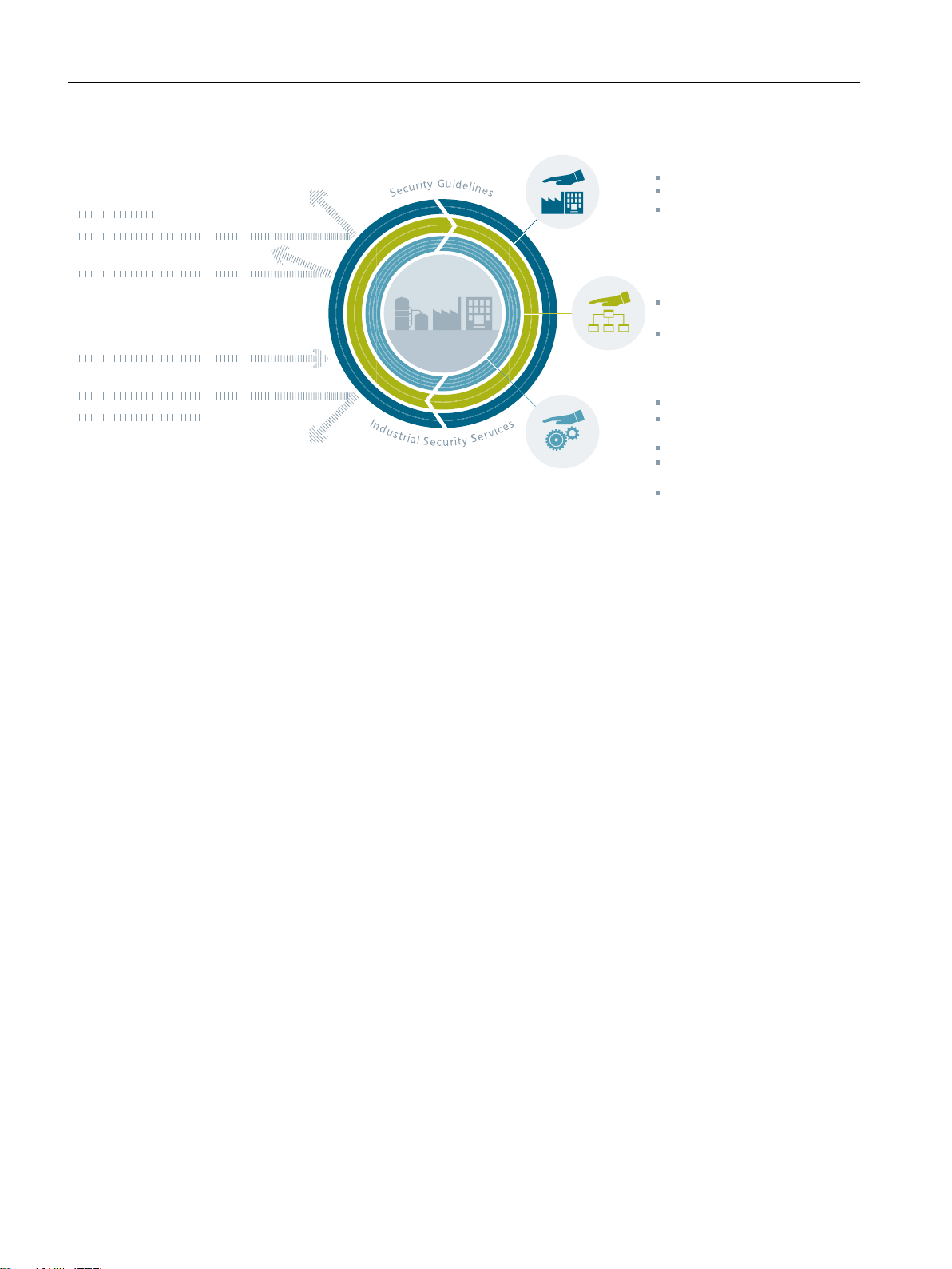
Basically, the measures should be coordinated with one another and correspond to the ringshaped principle of the "Defense in Depth" strategy. The measures are structured according
to the "onion" principle and each measure forms an additional protective layer around the core:
the production plant.
SIMOTION P320-4 E / P320-4 S
Commissioning and Hardware Installation Manual, 11/2016 27
6HFXULW\ULVNVGHPDQG
DFWLRQ
3K\VLFDODFFHVVSURWHFWLRQ
SURFHVVHVDQGVHFXULW\VHUYLFH
JXLGHOLQHVIRUWKHSURWHFWLRQRI
SURGXFWLRQSODQWV
3ODQWVHFXULW\
&HOOSURWHFWLRQ
SHULPHWHUQHWZRUN
ILUHZDOOVDQG931
1HWZRUNVHFXULW\
,QWHJUDWHGDFFHVVSURWHFWLRQ
LQWKHDXWRPDWLRQ
6\VWHPLQWHJULW\
6\VWHPKDUGHQLQJ
DXWKHQWLFDWLRQDQGXVHU
DGPLQLVWUDWLRQSDWFK
PDQDJHPHQWGHWHFWLRQ
RIDWWDFNV
'HIHQVHLQGHSWK
Industrial security
2.3 General security measures
Figure 2-1 Defense in depth strategy
● Plant security
Plant security represents the outermost protective ring. Plant security includes
comprehensive physical security measures, e.g. entry checks, which should be closely
coordinated with protective measures for IT security.
● Network security
The measures, grouped under the keyword "Network security", form the core of the
protective measures. This refers to the segmentation of the plant network with limited and
secure communication between subnetworks ("secure islands") and the interface check
with the use of firewalls.
● System integrity
"System integrity" represents the combination two major measures. PC-based systems and
the control level must be protected against attacks. Steps include the following measures:
– User authentication for machine or plant operators with individual authorization levels
– Integrated access protection mechanisms in the automation components to prevent
unauthorized changes via the engineering system or during maintenance
– The use of antivirus and whitelisting software to protect PC systems against malware
– Maintenance and update processes to keep the automation systems up-to-date
(e.g. patch management, firmware updates, etc.)
28 Commissioning and Hardware Installation Manual, 11/2016
SIMOTION P320-4 E / P320-4 S

2.3.2 Plant security
2.3.2.1 Physical protection of critical production areas
Unauthorized persons may be able to enter the production site/building and damage or alter
production equipment as a result of gaps in a company's physical security. Confidential
information can also be lost. This can be prevented if both the company's site and the
production areas are protected accordingly.
Company security
The company's physical security can be ensured via the following measures:
● Closed off and monitored company premises
● Entry control, keys / card readers and/or security personnel
● Escorting of external personnel by company employees
Physical production security
Industrial security
2.3 General security measures
Further information
The physical security of a production location can also be ensured via the following measures:
● Separate access control for production areas.
● Installation of critical components in securely lockable cabinets / switching rooms
including monitoring and alarm signaling options
● Prohibited production areas with restricted access rights
● Configuration of the radio field to restrict the WLAN range so that it is not available outside
the defined areas (e.g. factory building).
● Guidelines that prevent the use of third-party data storage media (e.g. USB sticks) and IT
devices (e.g. notebooks) classified as insecure on the control.
Further information on integrated security solutions can be found on the Surveillance page
(
http://www.buildingtechnologies.siemens.com/bt/global/en/security-solution/Pages/security-
solution.aspx).
SIMOTION P320-4 E / P320-4 S
Commissioning and Hardware Installation Manual, 11/2016 29

Industrial security
2.3 General security measures
2.3.3 Network security
2.3.3.1 Network segmentation
Separation between production and office networks
One important protective measure for your control is the strict separation of the production
networks and the other company networks. This separation creates protection zones for your
production networks.
Note
The products – drives, controllers, commissioning tools (e.g. STARTER or Startdrive) –
described in this manual must only be operated in protection zones.
Separation by means of a firewall system
In the simplest scenario, separation is achieved by means of an individual firewall system
which controls and regulates communication between networks.
Separation via a DMZ network
In the more secure version, the coupling is established via a separate DMZ network. In this
case, direct communication between the production network and the company network is
completely prevented by firewalls and only takes place indirectly via servers in the DMZ
network.
Note
The production networks should also be divided into separate automation cells in order to
protect critical communication mechanisms.
General security measures
Observe the general security measures even within protection zones, for example:
● Virus scanners (Page 33)
● Reduction of attack points (Page 33)
Network segmentation with SCALANCE S
Siemens provides SCALANCE S security modules to meet network protection and network
segmentation requirements.
SIMOTION P320-4 E / P320-4 S
30 Commissioning and Hardware Installation Manual, 11/2016
 Loading...