

Page 1

SIMOTION
SIMOTION P320-4 E / P320-4 S
Valid as of version V4.4
Preface
Manual
Safety instructions
Description
Application planning
Interfaces
Installation/mounting
Connection
Troubleshooting/FAQs
1
2
3
4
5
6
7
Technical data
Dimension drawings
Spare parts
Standards and approvals
ESD Guideline
8
9
10
A
B
01/2015
Page 2
Legal information
Warning notice system
This manual contains notices you have to observe in order to ensure your personal safety, as well as to prevent
damage to property. The notices referring to your personal safety are highlighted in the manual by a safety alert
symbol, notices referring only to property damage have no safety alert symbol. These notices shown below are
graded according to the degree of danger.
DANGER
indicates that death or severe personal injury will result if proper precautions are not taken.
WARNING
indicates that death or severe personal injury may result if proper precautions are not taken.
CAUTION
indicates that minor personal injury can result if proper precautions are not taken.
NOTICE
indicates that property damage can result if proper precautions are not taken.
If more than one degree of danger is present, the warning notice representing the highest degree of danger will be
used.
A notice warning of injury to persons with a safety alert symbol may also include a warning relating to property
damage.
Qualified Personnel
The product/system described in this documentation may be operated only by personnel qualified for the specific
task in accordance with the relevant documentation, in particular its warning notices and safety instructions. Qualified
personnel are those who, based on their training and experience, are capable of identifying risks and avoiding
potential hazards when working with these products/systems.
Proper use of Siemens products
Note the following:
WARNING
Siemens products may only be used for the applications described in the catalog and in the relevant technical
documentation.
If products and components from other manufacturers are used, these must be recommended or
approved by Siemens. Proper transport, storage, installation, assembly, commissioning, operation and
maintenance are required to ensure that the products operate safely and without any problems. The permissible
ambient conditions must be complied with. The information in the relevant documentation must be observed.
Trademarks
All names identified by ® are registered trademarks of Siemens AG. The remaining trademarks in this publication
may be trademarks whose use by third parties for their own purposes could violate the rights of the owner.
Disclaimer of Liability
We have reviewed the contents of this publication to ensure consistency with the hardware and software described.
Since variance cannot be precluded entirely, we cannot guarantee full consistency. However, the information in
this publication is reviewed regularly and any necessary corrections are included in subsequent editions.
Siemens AG
Division Digital Factory
Postfach 48 48
90026 NÜRNBERG
GERMANY
Ⓟ 03/2015 Subject to change
Copyright © Siemens AG 2015.
All rights reserved
Page 3

Preface
Preface
This document is part of the SIMOTION P documentation package.
This documentation describes the SIMOTION P320‑4 hardware platform which can be
delivered in the SIMOTION P320-4 E and SIMOTION P320-4 S hardware versions:
References
Validity range
Standards
● SIMOTION
real-time expansion for SIMOTION.
Successor to SIMOTION P320-3.
● SIMOTION P320‑4 E with the Windows 7 Ultimate 32-bit operating system and real-time
expansion for SIMOTION.
Successor to SIMOTION P350-3.
The following documents contain the descriptions for the SIMOTION P hardware platform:
● SIMOTION P320-4 E / P320-4 S, Manual, Edition 01/2015
● SIMOTION P320-4 E / P320-4 S, Commissioning and Hardware Installation Manual, Edition
01/2015
This manual applies to the SIMOTION P320-4 E and SIMOTION P320-4 S devices as of
product level SIMOTION V4.4.
The SIMOTION system was developed in accordance with ISO 9001 quality guidelines.
P320‑4 E with the Windows Embedded Standard 7 32-bit operating system and
Chapters in this documentation
The following sections describe the purpose and the use of this documentation:
● Safety instructions
Contains fundamental safety instructions for SIMOTION and specific safety instructions for
SIMOTION P320-4.
● Description
System overview and product description for SIMOTION P320-4. The communication
variants are also described.
● Use planning
Points to note in advance: upon delivery, the permitted installation positions, environmental
and ambient conditions and electromagnetic compatibility.
SIMOTION P320-4 E / P320-4 S
Manual, 01/2015 3
Page 4

Preface
● Interfaces
Description of the interfaces and operator control and display elements for
SIMOTION P320-4.
Installation/mounting
●
An overview of the installation of the SIMOTION P320-4 taking into account the mounting
positions.
● Connecting
This section provides general information and important notes that you must observe when
connecting the SIMOTION P320‑4.
● Troubleshooting/FAQs
List of possible errors and their remedies.
● Technical specifications
This section contains an overview of the technical data, which is listed for the individual
components.
● Dimension drawings
In this section you can find dimension drawings and dimensions of the SIMOTION P320‑4.
● Spare parts
You can find information about the spare parts for the SIMOTION P320-4 here.
● Appendix
In addition to the safety information, the annexes also contain information about the
standards, approvals and EGB guideline.
● Index
Alphabetical directory for locating information.
SIMOTION Documentation
An overview of the SIMOTION documentation can be found in the SIMOTION Documentation
Overview document.
This documentation is included as electronic documentation in the scope of delivery of
SIMOTION SCOUT. It comprises ten documentation packages.
The following documentation packages are available for SIMOTION V4.4:
● SIMOTION Engineering System Handling
● SIMOTION System and Function Descriptions
● SIMOTION Service and Diagnostics
● SIMOTION IT
● SIMOTION Programming
● SIMOTION Programming - References
● SIMOTION C
● SIMOTION P
SIMOTION P320-4 E / P320-4 S
4 Manual, 01/2015
Page 5

● SIMOTION D
SIMOTION Supplementary Documentation
●
Hotline and Internet addresses
Additional information
Click the following link to find information on the following topics:
● Ordering documentation / overview of documentation
● Additional links to download documents
● Using documentation online (find and search manuals/information)
http://www.siemens.com/motioncontrol/docu
My Documentation Manager
Click the following link for information on how to compile documentation individually on the
basis of Siemens content and how to adapt it for the purpose of your own machine
documentation:
Preface
Training
FAQs
Technical support
http://www.siemens.com/mdm
Click the following link for information on SITRAIN - Siemens training courses for automation
products, systems and solutions:
http://www.siemens.com/sitrain
Frequently Asked Questions can be found in SIMOTION Utilities & Applications, which are
included in the scope of delivery of SIMOTION SCOUT, and in the Service&Support pages
in Product Support:
http://support.automation.siemens.com
Country-specific telephone numbers for technical support are provided on the Internet under
Contact:
http://www.siemens.com/automation/service&support
Disposal and recycling of the device
The disposal of the products described in this manual must be performed in compliance with
the valid national regulations.
SIMOTION P320-4 E / P320-4 S
Manual, 01/2015 5
Page 6

Preface
To a great extent, the products can be recycled owing to their low pollutant content. To recycle
and dispose of your old device in an environmentally friendly way, please contact a waste
disposal service certified for electronic waste.
If you have any further questions about disposal and recycling, please contact your local
Siemens
contact person. Contact details can be found in our contacts database on the Internet
at: http://www.automation.siemens.com/partner/index.asp
SIMOTION P320-4 E / P320-4 S
6 Manual, 01/2015
Page 7

Table of contents
Preface.........................................................................................................................................................3
1 Safety instructions......................................................................................................................................11
1.1 Fundamental safety instructions............................................................................................11
1.1.1 General safety instructions.....................................................................................................11
1.1.2 Safety instructions for electromagnetic fields (EMF)..............................................................14
1.1.3 Handling electrostatic sensitive devices (ESD)......................................................................14
1.1.4 Industrial security...................................................................................................................15
1.1.5 Residual risks of power drive systems...................................................................................15
1.2 Specific safety instructions for the SIMOTION P320-4..........................................................18
1.2.1 General safety instructions for the SIMOTION P320-4..........................................................18
1.2.2 Notes on use..........................................................................................................................20
2 Description..................................................................................................................................................21
2.1 System overview....................................................................................................................21
2.2 SIMOTION P320-4 product description.................................................................................23
2.2.1 SIMOTION P320-4 overview..................................................................................................23
2.2.2 Features.................................................................................................................................24
2.2.3 SIMOTION P320-4 (hardware) structure...............................................................................26
2.2.4 Interfaces and operating elements.........................................................................................27
2.2.5 SIMOTION P Runtime (software) structure............................................................................27
2.2.6 Components...........................................................................................................................28
2.3 HMI and SIMOTION SCOUT.................................................................................................31
2.3.1 HMI and SIMOTION SCOUT Overview.................................................................................31
2.3.2 Local HMI or ES on SIMOTION P320-4.................................................................................31
2.3.3 HMI or ES via PROFINET......................................................................................................32
2.3.4 HMI or ES via Ethernet (external access) .............................................................................33
2.3.5 HMI or ES via IsoPROFIBUS (optional).................................................................................34
3 Application planning...................................................................................................................................37
3.1 Unpacking and checking the delivery.....................................................................................37
3.2 Identification data of the device..............................................................................................39
3.3 Permissible mounting positions..............................................................................................42
3.4 Environmental conditions.......................................................................................................43
3.5 Electromagnetic compatibility.................................................................................................45
4 Interfaces....................................................................................................................................................47
4.1 Hardware components of the SIMOTION P320-4..................................................................47
4.2 Overview of operator control and display elements...............................................................49
4.3 Control elements....................................................................................................................50
4.4 Status displays.......................................................................................................................51
SIMOTION P320-4 E / P320-4 S
Manual, 01/2015 7
Page 8

Table of contents
4.5 Overview of the SIMOTION P320-4 interfaces......................................................................53
4.6 PROFINET onboard...............................................................................................................54
4.7 Ethernet..................................................................................................................................55
4.8 DVI-I.......................................................................................................................................56
4.9 USB 3.0..................................................................................................................................58
4.10 CFast card .............................................................................................................................59
4.11 COM1.....................................................................................................................................60
4.12 IsoPROFIBUS board (optional)..............................................................................................61
5 Installation/mounting...................................................................................................................................63
5.1 Installing the device................................................................................................................63
5.2 Permissible mounting positions..............................................................................................64
5.2.1 Standard rail mounting and vertical mounting........................................................................65
5.2.1.1 Standard rail mounting...........................................................................................................65
5.2.1.2 Vertical mounting...................................................................................................................67
5.3 Installation notes....................................................................................................................69
5.4 Overview of operating modes for the SIMOTION P320-4......................................................71
5.5 Decentralized structure..........................................................................................................72
6 Connection.................................................................................................................................................73
6.1 Requirements.........................................................................................................................73
6.2 Overview of connections........................................................................................................74
6.3 Notes on connecting..............................................................................................................76
6.4 Protective conductor connection and potential equalization..................................................78
6.5 Connecting peripheral equipment..........................................................................................80
6.6 Connecting the power supply (24 VDC).................................................................................81
6.7 Connecting the device to networks........................................................................................83
6.8 Installing the strain relief........................................................................................................84
7 Troubleshooting/FAQs................................................................................................................................85
7.1 Error correction......................................................................................................................85
8 Technical data............................................................................................................................................87
8.1 Overview of the technical specifications................................................................................87
8.2 General technical specifications.............................................................................................88
8.3 Ambient conditions.................................................................................................................90
8.4 Technical data of the IsoPROFIBUS board...........................................................................92
8.5 Power requirements of the components................................................................................94
8.6 Integrated DC power supply...................................................................................................95
8.7 Technical data for the SITOP smart 24 V/10 A......................................................................96
SIMOTION P320-4 E / P320-4 S
8 Manual, 01/2015
Page 9

Table of contents
8.8 Typical power consumption....................................................................................................98
9 Dimension drawings...................................................................................................................................99
9.1 Overview of the dimensional drawings...................................................................................99
9.2 Device dimension drawing for standard rail mounting.........................................................100
9.3 Device dimension drawing for vertical mounting..................................................................102
9.4 Dimension drawing of device with one expansion card.......................................................105
10 Spare parts...............................................................................................................................................107
10.1 Available spare parts for SIMOTION P320-4.......................................................................107
A Standards and approvals..........................................................................................................................109
A.1 General rules........................................................................................................................109
B ESD Guideline..........................................................................................................................................111
B.1 ESD definition......................................................................................................................111
B.2 Electrostatic charging of individuals.....................................................................................112
B.3 Basic measures for protection against discharge of static electricity...................................113
Index.........................................................................................................................................................115
SIMOTION P320-4 E / P320-4 S
Manual, 01/2015 9
Page 10

Table of contents
SIMOTION P320-4 E / P320-4 S
10 Manual, 01/2015
Page 11
Safety instructions
1.1 Fundamental safety instructions
1
1.1.1
General safety instructions
DANGER
Danger to life due to live parts and other energy sources
Death or serious injury can result when live parts are touched.
Only work on electrical devices when you are qualified for this job.
●
● Always observe the country-specific safety rules.
Generally, six steps apply when establishing safety:
1. Prepare for shutdown and notify all those who will be affected by the procedure.
2. Disconnect the machine from the supply.
– Switch off the machine.
– Wait until the discharge time specified on the warning labels has elapsed.
– Check that it really is in a no-voltage condition, from phase conductor to phase
conductor and phase conductor to protective conductor.
– Check whether the existing auxiliary supply circuits are de-energized.
– Ensure that the motors cannot move.
3. Identify all other dangerous energy sources, e.g. compressed air, hydraulic systems, or
water.
4. Isolate or neutralize all hazardous energy sources by closing switches, grounding or shortcircuiting or closing valves, for example.
5. Secure the energy sources against switching on again.
6. Ensure that the correct machine is completely interlocked.
After you have completed the work, restore the operational readiness in the inverse sequence.
WARNING
Danger to life from hazardous voltage when connecting an unsuitable power supply
Touching live components can result in death or severe injury.
Only use power supplies that provide SELV (Safety Extra Low Voltage) or PELV
●
(Protective Extra Low Voltage) output voltages for all connections and terminals of the
electronics modules.
SIMOTION P320-4 E / P320-4 S
Manual, 01/2015 11
Page 12
Safety instructions
1.1 Fundamental safety instructions
WARNING
Danger to life from touching live parts on damaged devices
Improper handling of devices can result in damage.
For damaged devices, hazardous voltages can be present at the enclosure or at exposed
components; if touched, this can result in death or severe injury.
● Observe
the limit values specified in the technical specifications during transport, storage,
and operation.
● Do not use damaged devices.
WARNING
Danger to life through electric shock due to unconnected cable shields
Hazardous
touch voltages can occur through capacitive cross-coupling due to unconnected
cable shields.
● As a minimum, connect cable shields and the cores of power cables that are not used
(e.g. brake cores) at one end at the grounded housing potential.
WARNING
Danger to life due to electric shock when not grounded
For missing or incorrectly implemented protective conductor connection for devices with
protection
class I, high voltages can be present at open, exposed parts, which when touched,
can result in death or severe injury.
● Ground the device in compliance with the applicable regulations.
WARNING
Danger to life due to fire spreading if housing is inadequate
Fire and smoke development can cause severe personal injury or material damage.
● Install
devices without a protective housing in a metal control cabinet (or protect the device
by another equivalent measure) in such a way that contact with fire inside and outside the
device is prevented.
● Ensure that smoke can only escape via controlled and monitored paths.
SIMOTION P320-4 E / P320-4 S
12 Manual, 01/2015
Page 13

Safety instructions
1.1 Fundamental safety instructions
WARNING
Danger to life from unexpected movement of machines when using mobile wireless devices
or mobile phones
Using mobile radios or mobile phones with a transmit power > 1 W closer than approx. 2 m
to the components may cause the devices to malfunction, influence the functional safety of
machines therefore putting people at risk or causing material damage.
● Switch
off wireless devices or mobile phones in the immediate vicinity of the components.
WARNING
Danger to life due to fire if overheating occurs because of insufficient ventilation clearances
Inadequate
ventilation clearances can cause overheating of components followed by fire and
smoke development. This can cause death or serious injury. This can also result in increased
downtime and reduced service life for devices/systems.
● Ensure compliance with the specified minimum clearance as ventilation clearance for the
respective component.
WARNING
Danger of an accident occurring due to missing or illegible warning labels
Missing or illegible warning labels can result in accidents involving death or serious injury.
●
Check that the warning labels are complete based on the documentation.
● Attach any missing warning labels to the components, in the national language if
necessary.
● Replace illegible warning labels.
WARNING
Danger to life when safety functions are inactive
Safety functions that are inactive or that have not been adjusted accordingly can cause
operational faults on machines that could lead to serious injury or death.
● Observe
the information in the appropriate product documentation before commissioning.
● Carry out a safety inspection for functions relevant to safety on the entire system, including
all safety-related components.
● Ensure that the safety functions used in your drives and automation tasks are adjusted
and activated through appropriate parameterizing.
● Perform a function test.
● Only put your plant into live operation once you have guaranteed that the functions relevant
to safety are running correctly.
SIMOTION P320-4 E / P320-4 S
Manual, 01/2015 13
Page 14
Safety instructions
1.1 Fundamental safety instructions
Note
Important safety notices for safety functions
If you want to use safety functions, you must observe the safety notices in the safety manuals.
1.1.2 Safety instructions for electromagnetic fields (EMF)
WARNING
Danger to life from electromagnetic fields
Electromagnetic fields (EMF) are generated by the operation of electrical power equipment
such as transformers, converters or motors.
People with pacemakers or implants are at a special risk in the immediate vicinity of these
devices/systems.
Ensure that the persons involved are the necessary distance away (minimum 2 m).
●
1.1.3 Handling electrostatic sensitive devices (ESD)
Electrostatic
or devices that may be damaged by either electric fields or electrostatic discharge.
NOTICE
Damage through electric fields or electrostatic discharge
Electric
components, integrated circuits, modules or devices.
● Only pack, store, transport and send electronic components, modules or devices in their
original packaging or in other suitable materials, e.g conductive foam rubber of aluminum
foil.
● Only touch components, modules and devices when you are grounded by one of the
following methods:
– Wearing an ESD wrist strap
– Wearing ESD shoes or ESD grounding straps in ESD areas with conductive flooring
● Only place electronic components, modules or devices on conductive surfaces (table with
ESD surface, conductive ESD foam, ESD packaging, ESD transport container).
sensitive devices (ESD) are individual components, integrated circuits, modules
fields or electrostatic discharge can cause malfunctions through damaged individual
SIMOTION P320-4 E / P320-4 S
14 Manual, 01/2015
Page 15

1.1.4 Industrial security
Note
Industrial security
Siemens provides products and solutions with industrial security functions that support the
secure operation of plants, solutions, machines, equipment and/or networks. They are
important components in a holistic industrial security concept. With this in mind, Siemens’
products and solutions undergo continuous development. Siemens recommends strongly that
you regularly check for product updates.
For the secure operation of Siemens products and solutions, it is necessary to take suitable
preventive action (e.g. cell protection concept) and integrate each component into a holistic,
state-of-the-art industrial security concept. Third-party products that may be in use should also
be considered. For more information about industrial security, visit http://www.siemens.com/
industrialsecurity.
To stay informed about product updates as they occur, sign up for a product-specific
newsletter. For more information, visit http://support.automation.siemens.com
Safety instructions
1.1 Fundamental safety instructions
WARNING
Danger as a result of unsafe operating states resulting from software manipulation
Software manipulation (e.g. by viruses, Trojan horses, malware, worms) can cause unsafe
operating states to develop in your installation which can lead to death, severe injuries and/
or material damage.
Keep the software up to date.
●
Information and newsletters can be found at:
http://support.automation.siemens.com
● Incorporate the automation and drive components into a state-of-the-art, integrated
industrial security concept for the installation or machine.
For more detailed information, go to:
http://www.siemens.com/industrialsecurity
● Make sure that you include all installed products into the integrated industrial security
concept.
1.1.5 Residual risks of power drive systems
control and drive components of a drive system are approved for industrial and commercial
The
use in industrial line supplies. Their use in public line supplies requires a different configuration
and/or additional measures.
These components may only be operated in closed housings or in higher-level control cabinets
with protective covers that are closed, and when all of the protective devices are enabled.
These components may only be handled by qualified and trained technical personnel who are
knowledgeable and observe all of the safety instructions on the components and in the
associated technical user documentation.
SIMOTION P320-4 E / P320-4 S
Manual, 01/2015 15
Page 16

Safety instructions
1.1 Fundamental safety instructions
When assessing the machine's risk in accordance with the respective local regulations (e.g.
EC Machinery Directive), the machine manufacturer must take into account the following
residual risks emanating from the controller and drive components of a drive system:
1. Unintentional
movements of driven machine components during commissioning, operation,
maintenance, and repairs caused by, for example:
– Hardware defects and/or software errors in the sensors, controllers, actuators, and
connection technology
– Response times of the controller and drive
– Operating and/or ambient conditions outside of the specification
– Condensation / conductive contamination
– Parameterization, programming, cabling, and installation errors
– Use of radio devices / cellular phones in the immediate vicinity of the controller
– External influences / damage
2. In the event of a fault, exceptionally high temperatures, including an open fire, as well as
emissions of light, noise, particles, gases, etc. can occur inside and outside the inverter,
for example:
– Component malfunctions
– Software errors
– Operating and/or ambient conditions outside of the specification
– External influences / damage
Inverters of the Open Type / IP20 degree of protection must be installed in a metal control
cabinet (or protected by another equivalent measure) such that the contact with fire inside
and outside the inverter is not possible.
3. Hazardous touch voltages caused by, for example:
– Component malfunctions
– Influence of electrostatic charging
– Induction of voltages in moving motors
– Operating and/or ambient conditions outside of the specification
– Condensation / conductive contamination
– External influences / damage
4. Electrical, magnetic and electromagnetic fields generated in operation that can pose a risk
to people with a pacemaker, implants or metal replacement joints, etc. if they are too close.
5. Release of environmental pollutants or emissions as a result of improper operation of the
system and/or failure to dispose of components safely and correctly.
SIMOTION P320-4 E / P320-4 S
16 Manual, 01/2015
Page 17

Safety instructions
1.1 Fundamental safety instructions
Note
The components must be protected against conductive contamination (e.g. by installing them
in a control cabinet with degree of protection IP54 according to IEC 60529 or NEMA 12).
Assuming that conductive contamination at the installation site can definitely be excluded, a
lower degree of cabinet protection may be permitted.
For more information about residual risks of the components in a drive system, see the relevant
sections in the technical user documentation.
SIMOTION P320-4 E / P320-4 S
Manual, 01/2015 17
Page 18

Safety instructions
1.2 Specific safety instructions for the SIMOTION P320-4
1.2 Specific safety instructions for the SIMOTION P320-4
1.2.1
General safety instructions for the SIMOTION P320-4
Life-threatening voltages are present with an open control cabinet
When you install the device in a control cabinet, some areas or components in the open
control cabinet may be carrying life-threatening voltages.
If you touch these areas or components, you may be killed by electric shock.
Switch off the power supply to the cabinet before opening it.
System expansions
NOTICE
Damage through system expansions
Device and system expansions may be faulty and can affect the entire machine or plant.
The installation of expansions can damage the device, machine or plant.
Device and system expansions may violate safety rules and regulations regarding radio
interference suppression.
WARNING
you install or exchange system expansions and damage your device, the warranty becomes
If
void.
Note the following for system expansions:
●
Only install system expansion devices designed for this device. Contact your technical
support team or where you purchased your PC to find out which system expansion devices
may safely be installed.
● Observe the information on electromagnetic compatibility (Page 109).
NOTICE
"Open Type" UL508
Note that the device is classified as "Open Type" for use in the area of Industrial Control
Equipment (UL508). Installation of the device in an enclosure according to UL508 is
conditional for approval or operation according to UL508.
SIMOTION P320-4 E / P320-4 S
18 Manual, 01/2015
Page 19

Battery and rechargeable battery
WARNING
Risk of explosion and release of harmful substances
Improper handling of lithium batteries can result in an explosion of the batteries.
Safety instructions
1.2 Specific safety instructions for the SIMOTION P320-4
Explosion
batteries jeopardize the function of the device.
Note the following when handling lithium batteries:
● Replace used batteries in good time, see the section "Replacing the backup battery" in
the Commissioning and Hardware Installation Manual.
● Replace the lithium battery only with an identical battery or types recommended by the
manufacturer (Article No.: A5E30314053).
● Do not throw lithium batteries into fire, do not solder on the cell body, do not recharge, do
not open, do not short-circuit, do not reverse polarity, do not heat above 100°C and protect
from direct sunlight, moisture and condensation.
High frequency radiation
NOTICE
Unintentional operating situations
frequency radiation, e g. from a cellular phone, interferes with device functions and can
High
result in malfunctioning of the device.
Persons are injured and the plant is damaged.
Avoid high-frequency radiation:
● Remove radiation sources from the environment of the device.
● Switch off radiating devices.
● Reduce the radio output of radiating devices.
● Observe the information on electromagnetic compatibility (Page 109).
of the batteries and the released pollutants can cause severe physical injury. Worn
ESD Guideline
Electrostatic sensitive devices can be labeled with an appropriate symbol.
NOTICE
Electrostatic sensitive devices (ESD)
When
you touch electrostatic sensitive components, you can destroy them through voltages
that are far below the human perception threshold.
If you work with components that can be destroyed by electrostatic discharge, observe the
ESD Guideline.
SIMOTION P320-4 E / P320-4 S
Manual, 01/2015 19
Page 20

Safety instructions
1.2 Specific safety instructions for the SIMOTION P320-4
Further information
can find more detailed information about the EGB Guideline in Annex B in the section with
You
the same name.
1.2.2 Notes on use
WARNING
Hazards on an unprotected machine or plant
According to the results of a risk analysis, hazards can occur on an unprotected machine.
The hazards can result in personal injury.
According to the risk analysis, the risk of personal injury can be avoided with the following
measures:
Additional protective devices on the machine or plant. With this, especially the
●
programming, configuration and wiring of the inserted I/O modules have to be executed,
in accordance with the necessary risk analysis identified safety performance (SIL, PL or
Cat.).
● The correct use of the device has to be verified with a function test on the system. This
test can detect programming, configuration and wiring errors.
● Documentation of the test results that you can enter in the relevant safety records when
required.
NOTICE
Ambient conditions
Ambient
Note the following:
● Operate the device only in closed rooms. Failure to comply nullifies the warranty.
● Operate the device only in accordance with the ambient conditions specified in the
● Protect the device against dust, moisture and heat.
● Do not expose the device to direct sunlight or other strong sources of light.
● Without additional measures, such as a supply of clean air, the device may not be used
● Observe the permissible mounting positions of the device.
● Do not obstruct the venting slots of the device.
Note
Use in an industrial environment without additional protective measures
This device was designed for use in a normal industrial environment according to
IEC 60721-3-3.
conditions for which the device is not suitable can cause faults or damage the device.
technical specifications.
in locations with harsh operating conditions caused by acidic vapors or gases.
SIMOTION P320-4 E / P320-4 S
20 Manual, 01/2015
Page 21

Description
2.1 System overview
Overview
SIMOTION P is a PC-based, open Motion Control System from SIMOTION.
Control, motion control, and HMI functions are executed together with standard PC
applications
of the Windows operating system with real-time capability of SIMOTION P Runtime.
The fully independent SIMOTION P Runtime runs in parallel to Windows on SIMOTION P.
This real-time expansion makes it possible to implement demanding motion control
applications with high performance requirements on platforms of the SIMOTION P range. The
hardware consists of a computing unit with innovative Intel technology, which is ready for
operation at the time of delivery.
The drives and I/O devices are connected either via PROFINET onboard or
IsoPROFIBUS board (optional).
The SIMATIC flat panels IFP1500, IFP1900 and IFP2200 can be used for the operation of the
SIMOTION P320-4 hardware platform in a distributed configuration.
on the SIMOTION P hardware platform. SIMOTION P combines the compatibility
2
Variants of the SIMOTION P320-4
The SIMOTION P320-4 S can control various I/O systems and HMI components via
PROFINET onboard or the optional IsoPROFIBUS board.
A USB DVD drive can be connected, for example.
The following variants of the SIMOTION P320-4 are available:
● SIMOTION P320-4 E
with the Windows Embedded Standard 7 32-bit operating system and real-time expansion
for SIMOTION.
● SIMOTION P320-4 S
with the Windows 7 Ultimate 32-bit operating system and real-time expansion for
SIMOTION.
Application
The SIMOTION P320-4 applications are directed at machines that require a high level of
integration of PLC, motion control and technology functions on account of the increasing use
of servo drives:
● Packaging machines
● Plastic and rubber processing machines
● Presses, wire-drawing machines
● Textile machines
SIMOTION P320-4 E / P320-4 S
Manual, 01/2015 21
Page 22

Description
2.1 System overview
● Printing machines
●
● Production lines in the renewable energy sector, e.g. solar technology, wind power
Machines for processing wood, glass, ceramics, and stone
installations
SIMOTION P320-4 E / P320-4 S
22 Manual, 01/2015
Page 23
2.2 SIMOTION P320-4 product description
Description
2.2 SIMOTION P320-4 product description
2.2.1
SIMOTION P320-4 overview
The SIMOTION P320-4 provides high-level industrial performance. It features:
● Compact design
● Maintenance-free operation
● High degree of ruggedness
● Long-term availability
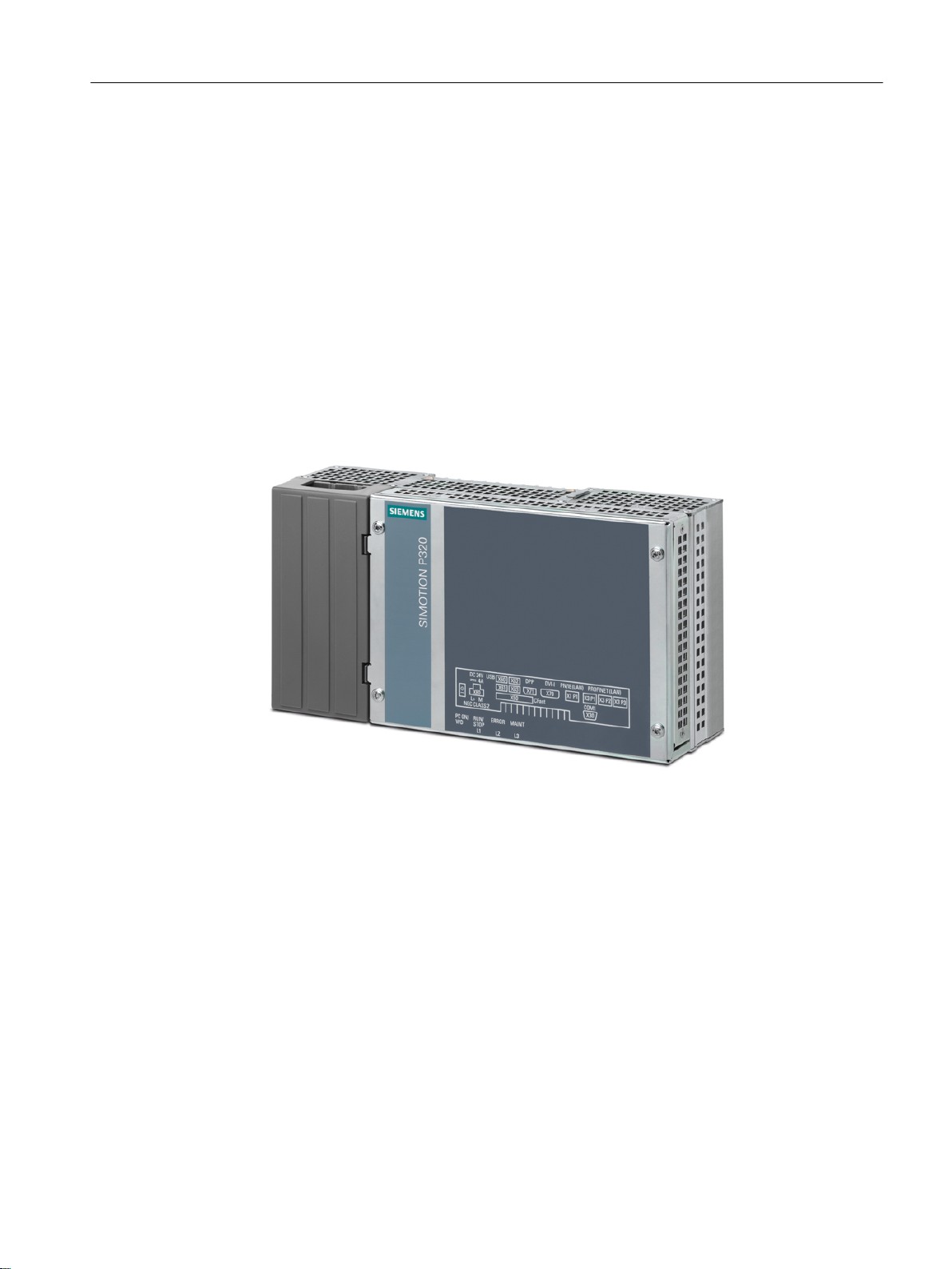
Figure 2-1 SIMOTION P320-4 view
SIMOTION P320-4 E / P320-4 S
Manual, 01/2015 23
Page 24
Description
2.2 SIMOTION P320-4 product description
2.2.2
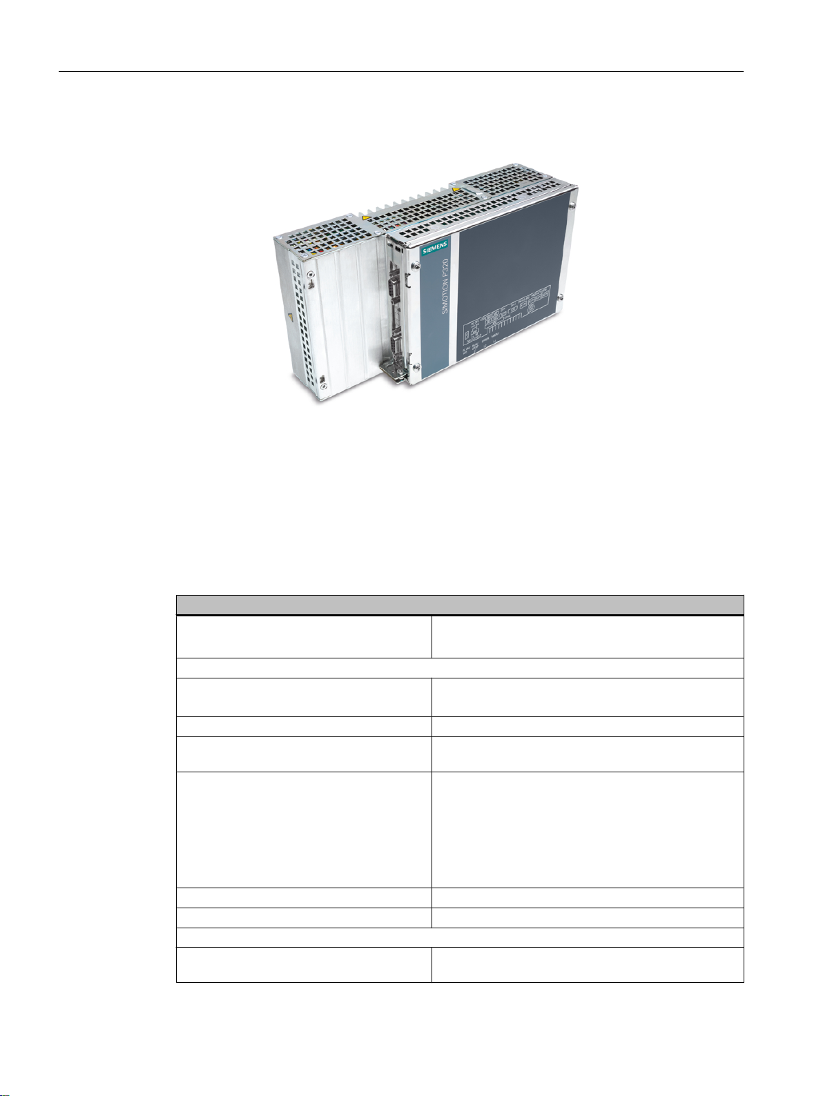
Figure 2-2 SIMOTION P320-4 (open perspective) with plugged-in optional IsoPROFIBUS board
Features
Basic data
Installation
Processor
P320-4 E
P320-4 S
Main memory 4 GB DDR3 RAM
Optional IsoPROFIBUS board
(PROFIBUS DP)
Graphics
Power supply 24 VDC (-20%/+20%) max. 4 A
Operating conditions Operation without fan
Drives and storage media
CFast card or SSD
(Solid State Disk)
● Standard rail mounting
Vertical mounting
●
Intel Core i3-3217UE, 2 x 1.6 GHz, 3 MB cache
Intel Core i7-3517UE, 2 x 1.7 GHz, 4 MB cache
2 x SUB-D socket with configurable baud rates (9.6 Kbit/
s - 12 Mbps)
● Integrated Intel HD2000 or HD4000
DVI resolution of 640 × 480 pixels up to
●
1920 × 1200 pixels
● Display port resolution max. 1920 × 1200 pixels
● Graphics memory is claimed in main memory
(dynamic UMA)
SIMOTION P320-4 E / P320-4 S
24 Manual, 01/2015
Page 25

Description
2.2 SIMOTION P320-4 product description
Basic data
P320-4 E 2 x CFast card
Internal interface: CFast
External interface: CFast
P320-4 S SSD (Solid State Disk)
Internal interface: SSD
CFast card
External interface: CFast
USB stick External, can be connected via USB interface
Interfaces
Serial COM (RS 232)
Graphics DVI-I: suitable for use as DVI or VGA
DPP++: Display port, DVI via DPP-to-DVI adapter
USB 4 × USB 3.0, simultaneous operation of high current,
backward compatible with USB 2.0/1.1
Ethernet 1 × RJ45 (10/100/1000 Mbps)
PROFINET I/O 3 × RJ45 (100 Mbps)
Keyboard, mouse Can be connected via USB interface
Software
Operating systems
P320-4 E Windows Embedded Standard 7 32-bit
P320-4 S Windows 7 Ultimate 32-bit
SIMOTION P320-4 E / P320-4 S
Manual, 01/2015 25
Page 26
7)7PRQLWRU
7)7PRQLWRU
'9,9*$
;
'LVSOD\SRUW
DOWHUQDWLYH
DOWHUQDWLYH
352),1(7GULYHV
HJ6,1$0,&66
352),1(7b,2
HJ(763
+0,3*(6
352),1(7
352),1(7
352),1(7
2QERDUG
(WKHUQHW
+0,3*(6
(WKHUQHW
.H\ERDUGDQG
0RXVH
86%
;
352),%86'3
352),1(7GULYHV
H
J6,1$0,&66
352),1(7b,2
HJ(763
+0,3*(6
352),1(7RQERDUGFRQWUROOHU
+0, +XPDQ0DFKLQH,QWHUIDFH
3* 3URJUDPPLQJ'HYLFH
(6 (QJLQHHULQJ6\VWHP
6HULDO
,QWHUIDFH
%XIIHUHG
65$0
5HWDLQGDWD
352),%86'3
ืP0EDXG
,VR352),%86ERDUGRSWLRQDO
$QDORJ,2PRGXOHV
$',GULYHLQWHUIDFH
6,0$7,&(7
HJ(763
352),%86'3
'ULYHV
6,0$7,&(7
HJ(763
$QDORJ,2PRGXOHV
$',GULYHLQWHUIDFH
352),%86GULYHV
HJ6,1$0,&66
6<1&,2FRQQHFWLQJFDEOH
3DQHOV
3DQHOV
;
;
;
;
6,027,213
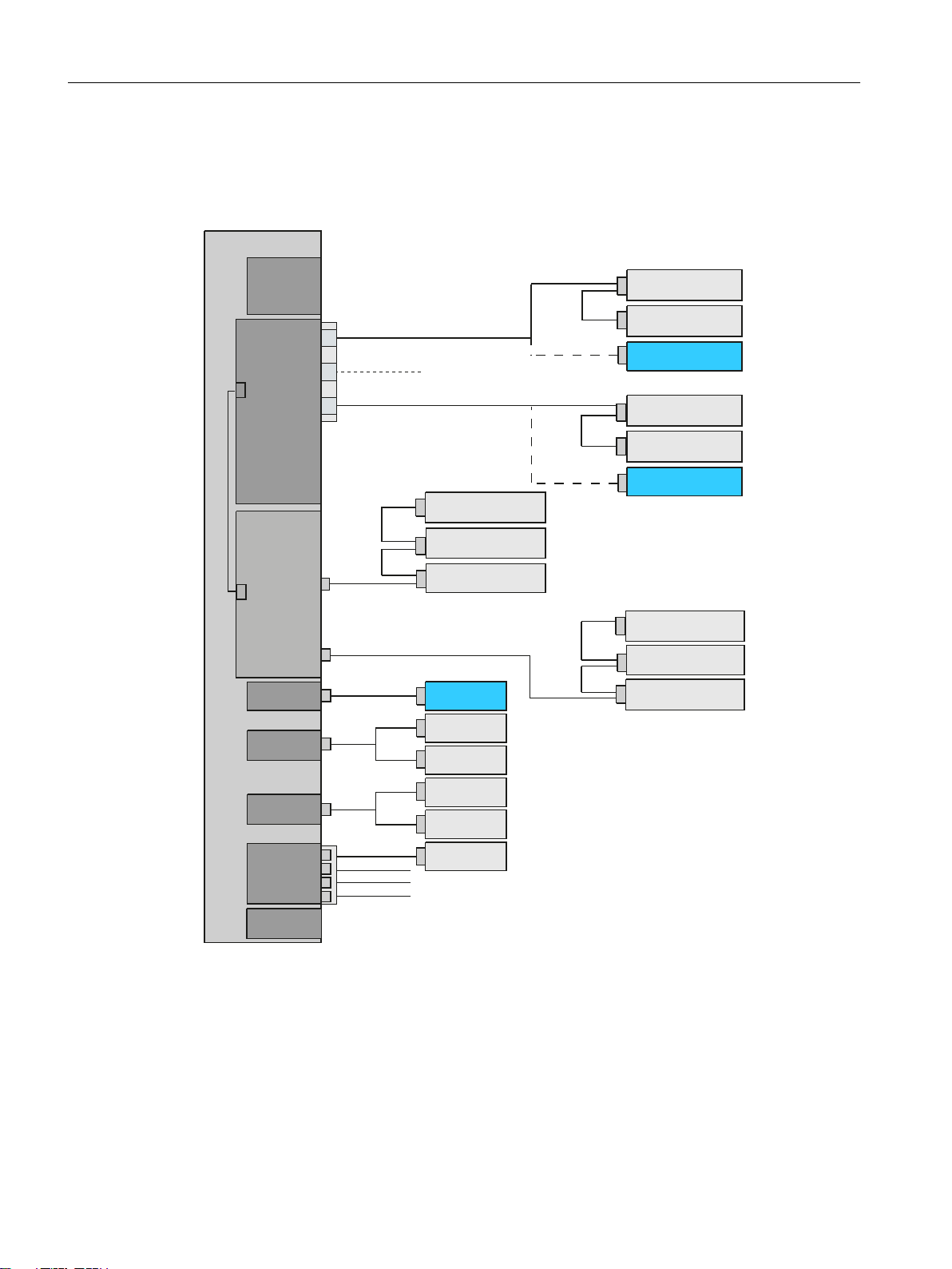
Description
2.2 SIMOTION P320-4 product description
2.2.3 SIMOTION P320-4 (hardware) structure
following figure shows the integration of the SIMOTION P320-4 with integrated PROFINET
The
onboard and optional IsoPROFIBUS board in a target system.
Figure 2-3 System overview of the SIMOTION P320-4
26 Manual, 01/2015
SIMOTION P320-4 E / P320-4 S
Page 27
2.2.4 Interfaces and operating elements
SIMOTION P320-4
① On/off switch Position OFF is the delivery state.
The on/off switch does not isolate the device from the power sup‐
ply.
② 24 V DC Power supply connection
③ Protective conductor Protective conductor terminal
④ Memory card slot Cover for the CFast card
⑤ 4 × USB 3.0 USB 3.0 high current, backward compatible with USB 2.0/1.1
⑥ Display port Display port connection for digital monitor
⑦ DVI-I DVI connector for CRT or LCD monitor with DVI interface
⑧ Ethernet RJ45 Ethernet connection for 10/100/1000 Mbps
⑨ COM1 Serial interface
⑩ 3 × PROFINET PROFINET ports with three RJ45 sockets
Description
2.2 SIMOTION P320-4 product description
2.2.5 SIMOTION P Runtime (software) structure
SIMOTION P320-4 E / P320-4 S
Manual, 01/2015 27
SIMOTION P contains the SIMOTION P Kernel which performs the motion control and
interface control.
A SIMOTION P project is planned, configured, assigned parameters, commissioned, and
programmed by means of the SIMOTION SCOUT Engineering System (ES).
User data can be stored on the data media of the SIMOTION P320‑4.
Siemens
the machine. Third-party systems can be linked via the OPC interface.
WinCC flexible software can be used to visualize operational sequences or to operate
Page 28

Description
2.2 SIMOTION P320-4 product description
SIMOTION P Runtime
With the SIMOTION P320-4, the PLC and motion control functionality (starting from position
controller upwards) is located centrally in a strictly deterministic task outside the Windows
operating system.
Its main field of application is centralized motion control and control tasks requiring close
coordination between multiple axes and/or input/output modules.
Functionality ranges from simple positioning to high-performance synchronous operation.
SIMOTION SCOUT
The SIMOTION SCOUT engineering system can be installed on the SIMOTION P320-4 S or
connected via the interfaces integrated in SIMOTION P320‑4.
HMI software
HMI/Runtime software can be operated on the same PC, e.g. the Siemens WinCC flexible
software. Other software packages can be linked by means of the OPC interface.
The HMI software is used as the general term in the following.
Internal communication
A locally installed HMI can use the local communication to access the following:
Variables in SIMOTION RT
●
● Drives on PROFINET IO or PROFIBUS DP
● Other SIMOTION devices on PROFINET IO or PROFIBUS DP
Scope of delivery
The system software supplied with the SIMOTION P320-4 is either already installed on the
SIMOTION P320‑4 storage medium or is ready to be installed:
● SIMOTION P Kernel
● SIMOTION IT
● SIMOTION IT VM Virtual Machine (under license)
2.2.6 Components
The most important components of the SIMOTION P320-4 and their functions are listed below.
SIMOTION P320-4 E / P320-4 S
28 Manual, 01/2015
Page 29

Distributed I/O systems (PROFINET)
Description
2.2 SIMOTION P320-4 product description
Table 2-1
Component Function
SIMATIC ET 200M Modular I/O system for control cabinet installation and high channel densities.
SIMATIC ET 200S Finely modular I/O system for control cabinet installation including motor
SIMATIC ET 200SP Finely scalable I/O system for cabinet installation; SIMATIC ET 200SP fea‐
SIMATIC ET 200MP Modular I/O system for cabinet installation and high channel densities in the
SIMATIC ET 200eco I/O system with IP67 degree of protection for machine-related, cabinet-free
SIMATIC ET 200pro Modular I/O system with IP65/67 degree of protection for machine-related,
Components for distributed I/O
starters, safety technology, and individual grouping of the load groups.
tures a single-cable and multi-cable connection with push‑in terminals, com‐
pact dimensions, high performance, and low part variety.
SIMATIC S7‑1500 packaging system.
SIMATIC ET 200MP permits the shortest bus cycle times and fastest re‐
sponse time even with large volumes of data.
applications,
M12.
cabinet-free applications, including motor starters.
featuring a flexible and fast connection system in ECOFAST or
Note
Please
note that not all modules of the above-mentioned I/Os or I/O systems are approved for
SIMOTION.
Moreover, system-related functional differences can occur when these I/O or I/O systems are
used on SIMOTION rather than SIMATIC.
For example, special process-control functions (e.g., HART modules, etc.) are not supported
by SIMOTION for the ET 200M distributed I/O system.
For a detailed and routinely updated list of I/O modules enabled with SIMOTION as well as
application information, visit us online at:
siemens.com - Industry Automation and Drive Technologies - Product Support Supplementary System Components (
http://support.automation.siemens.com/WW/view/en/
11886029)
Further modules are integrated via the GSD file of the device's manufacturer.
Note
Please note that in individual cases, additional general conditions must be fulfilled.
SIMOTION P320-4 E / P320-4 S
Manual, 01/2015 29
Page 30

Description
2.2 SIMOTION P320-4 product description
Drive systems (via PROFINET IO)
Table 2-2
Component Function
SINAMICS S120 Servo drives, innovative single-axis and multi-axis solution
Optional components
Table 2-3 Optional components
Centralized I/O Function
IsoPROFIBUS board PROFIBUS connection
UPS Uninterruptible Power Supply
Note
In addition, an IsoPROFIBUS board may be inserted for the PROFINET onboard.
List of typically connected drive systems
SIMOTION P320-4 E / P320-4 S
30 Manual, 01/2015
Page 31

2.3 HMI and SIMOTION SCOUT
Description
2.3 HMI and SIMOTION SCOUT
2.3.1
HMI and SIMOTION SCOUT Overview
The operational sequences on the SIMOTION P320-4 are either monitored via the HMI system
(Human Machine Interface) or the SIMOTION SCOUT engineering system.
The HMI or ES software can be connected using the following variants:
● Local (Page 31)
● via PROFINET (Page 32)
● via Ethernet (Page 33)
● via IsoPROFIBUS (optional) (Page 34)
Local communication of the HMI/ES
Only one local connection to the local SIMOTION Runtime is possible. If HMI or ES is also
installed locally, PC internal can access other controllers/devices via PROFINET / PROFIBUS.
See section Local HMI or ES on SIMOTION P320-4 (Page 31)
Communication of the HMI / ES via PROFINET / Ethernet / PROFIBUS
By using one of these communication variants, you can control and monitor several
SIMOTION devices.
2.3.2 Local HMI or ES on SIMOTION P320-4
For communication of the SIMOTION P320-4 with a local HMI or ES, the model described
below is used. The SIMOTION SCOUT engineering system or the HMI system can be installed
directly on the SIMOTION P320-4 S.
For this model, you must set the communication (access point) to PC internal. The
SIMOTION P320-4 is already configured for this communication variant at the time of delivery.
SIMOTION P320-4 E / P320-4 S
Manual, 01/2015 31
Page 32

,2
GULYHV
,2
GULYHV
+0,(6
352),%86'3
352),1(7,2
6,027,213
Description
2.3 HMI and SIMOTION SCOUT
Figure 2-4 Set PG/PC Interface dialog
Note
Only HMI-Runtime can be installed on the SIMOTION P320-4 E version.
Figure 2-5 Model: Local HMI or ES
2.3.3 HMI or ES via PROFINET
Networking via PROFINET
PROFINET is the innovative and open Industrial Ethernet standard (EN 61158) for industrial
automation. With PROFINET, devices can be linked up from the field level through to the
management level.
32 Manual, 01/2015
SIMOTION P320-4 E / P320-4 S
Page 33

+0,(6
352),1(7
,2
'ULYHV
,2
'ULYHV
35
2),1(7b,2
352),%86'3
,2
'ULYHV
,2
'ULYHV
352),1(7b,2
352),%86'3
6,027,2136,027,213
References
,2
GULYHV
,2
GULYHV
,2
GULYHV
,2
GULYHV
352),1(7,2
352),%86'3
35
2),1(7,2
352),%86'3
(WKHUQHW
+0,(6
6,027,213
6,027,213
Description
2.3 HMI and SIMOTION SCOUT
With PROFINET, an external HMI or ES can also be integrated into the network and data can
be exchanged directly with the SIMOTION P320-4 device.
Figure 2-6 Model: Networking via PROFINET
You can find further information on the HMI in the documentation:
●
SIMOTION Runtime Basic Functions, section HMI (Human Machine Interface) coupling.
2.3.4 HMI or ES via Ethernet (external access)
Networking via Ethernet
A complex interconnection with several HMIs or ESs is only possible using an Ethernet
communication. This allows both an external HMI or ES to access several SIMOTION devices
or one SIMOTION device to access another one, for example, to display the production data.
SIMOTION P320-4 E / P320-4 S
Manual, 01/2015 33
Figure 2-7 Model: Networking via Ethernet
Page 34

+0,(6
352),%86'3
,2
'ULYHV
352),%86'3
,2
'ULYHV
352),%86'3
6,027,2136,027,213
;
;;
;
Description
2.3 HMI and SIMOTION SCOUT
Using Ethernet, the following services are possible on a SIMOTION device:
HMI software
●
WinCC flexible or the OPC server can use Ethernet to access one or more SIMOTION
devices.
● SIMOTION SCOUT Engineering System
SIMOTION SCOUT can also use Ethernet to access one or more SIMOTION devices.
● SIMOTION IT
SIMOTION P320-4 offers communication with standard IT protocols (HTTP) over the
integrated Ethernet interface.
This makes it possible to access data or diagnostic information in the SIMOTION P320-4
from any location via intranet or the Internet.
References
You can find further information in the documentation for SIMOTION IT:
● SIMOTION IT Diagnostics and Configuration
● SIMOTION IT Programming and Web Services
● SIMOTION IT Virtual Machine and Servlets
2.3.5 HMI or ES via IsoPROFIBUS (optional)
Networking via PROFIBUS DP
If you connect a central HMI via PROFIBUS DP, the X101 and X102 interfaces of the
IsoPROFIBUS board are available.
Figure 2-8 Model: Networking via PROFIBUS DP
34 Manual, 01/2015
SIMOTION P320-4 E / P320-4 S
Page 35

References
Description
2.3 HMI and SIMOTION SCOUT
You can find further information on the HMI in the documentation:
SIMOTION Runtime Basic Functions, section HMI (Human Machine Interface) coupling.
●
SIMOTION P320-4 E / P320-4 S
Manual, 01/2015 35
Page 36

Description
2.3 HMI and SIMOTION SCOUT
SIMOTION P320-4 E / P320-4 S
36 Manual, 01/2015
Page 37

Application planning
3.1 Unpacking and checking the delivery
Procedure
When accepting a delivery, please check the packaging for visible transport damage.
1.
2. If any transport damage is present at the time of delivery, lodge a complaint at the shipping
company in charge. Have the shipper confirm the transport damage immediately.
3. Unpack the device at its installation location.
4. Keep the original packaging in case you have to transport the device again.
Note
Damage to the device during transport and storage
If a device is transported or stored without packaging, then shocks, vibrations, pressure
and moisture may impact the unprotected device.
damaged packaging indicates that ambient conditions have already had a massive impact
A
on the device.
The device may be damaged.
3
Do not dispose of the original packaging. Pack the device for transport and storage in the
original packaging.
5. Check the contents of the packaging and any accessories you may have ordered for
completeness and damage.
SIMOTION P320-4 E / P320-4 S
Manual, 01/2015 37
Page 38

Application planning
3.1 Unpacking and checking the delivery
the contents of the packaging are incomplete, damaged or do not match your order, inform
6. If
the responsible delivery service immediately.
WARNING
Electric shock and fire hazard due to damaged device
A damaged device can be under hazardous voltage and trigger a fire in the machine or
plant. A damaged device has unpredictable properties and states.
Death or serious injury could occur.
Make sure that the damaged device is not inadvertently installed and put into operation.
Label the damaged device and keep it locked away. Send off the device for immediate
repair.
NOTICE
Damage from condensation
the device is subjected to low temperatures or extreme fluctuations in temperature during
If
transportation, for example in cold weather, moisture could build up on or inside the HMI
device.
Moisture can result in short-circuits in electrical circuits and damage the device.
In order to prevent damage to the device, proceed as follows:
● Store the device in a dry place.
● Bring the device to room temperature before starting it up.
● Do not expose the device to direct heat radiation from a heating device.
● If condensation develops, wait approximately 12 hours or until the device is completely
dry before switching it on.
7. Please keep the enclosed documentation, it belongs to the device. You need the
documentation when you commission the device for the first time.
8.
Write down the identification data of the device.
SIMOTION P320-4 E / P320-4 S
38 Manual, 01/2015
Page 39

3.2 Identification data of the device
Application planning
3.2 Identification data of the device
Based
on the identification data, the SIMOTION P320-4 device can be identified when service
is required or in case of theft.
You also require the identification data in order to view further information on your
SIMOTION P320-4 in the Product Equipment Data (PED) database.
All the important components of your SIMOTION P320-4 are stored in the PED. The entire
history of the device is stored there, including the service reports.
To identify yourself in the PED database, enter the article number and the serial number of
your device.
Link to the PED database
The Product Equipment Data database is available on the Internet via the following link (
www.siemens.com/ped).
Identification data
Enter the identification data in the following table:
Identification data Source Value
Serial number Type plate S VP ...
Article number of the device Type plate 6AU1320-...
Microsoft Windows Product Key
Certificate of Authenticity (COA)
Ethernet address 1 BIOS setup, menu "Advanced", "Pe‐
PROFINET onboard MAC Address Layer 2
PROFINET onboard MAC Address PROFINET
Rear of the device Only devices with preinstalled
Windows
COA labels
Input by the user.
ripheral Configuration"
http://
operating systems have
SIMOTION P320-4 type plate
Example of SIMOTION P320-4 S (standard)
You will find the following data on the type plate of the SIMOTION P320-4:
Device designation (here): SIMOTION P320-4 S
●
● Article number of the device (here): 6AU1320-4DS66-3AG0
● Serial number S VP<...>
The computing unit is uniquely identifiable with the serial number at S VP <...>.
<...> <...> is an 8-digit character string.
● cULus Approval
● CE marking
SIMOTION P320-4 E / P320-4 S
Manual, 01/2015 39
Page 40

Application planning
3.2 Identification data of the device
Figure 3-1 SIMOTION P320-4 type plate
MAC addresses
Example of SIMOTION P320-4 S (standard)
In addition to the data that is found on the SIMOTION P320-4 type plate, the MAC address
plate also contains the Onboard MAC addresses for:
●
ETHERNET (LAN) X1: VIPCTYSMAC1
● PROFINET (LAN) X3: VIPCTYSPROFINET
The data cited here is not real data.
Figure 3-2 Type plate SIMOTION P320-4 S - MAC addresses
SIMOTION P320-4 E / P320-4 S
40 Manual, 01/2015
Page 41

Example of a COA label
Microsoft Windows "Product Key" of the "Certificate of Authenticity" (COA):
COA label is attached to the rear of all devices containing a Windows Embedded Standard
The
7 or Windows 7 operating system.
● COA label of a device with Windows Embedded Standard 7 32-bit operating system
Figure 3-3 ipc477d label coa 01
COA label of a device with Windows 7 operating system
●
Application planning
3.2 Identification data of the device
SIMOTION P320-4 E / P320-4 S
Manual, 01/2015 41
Page 42

Application planning
3.3 Permissible mounting positions
3.3 Permissible mounting positions
Information
the section Installation/mounting > Permissible mounting positions (Page 64).
on the permissible mounting positions for the SIMOTION P320-4 can be found in
SIMOTION P320-4 E / P320-4 S
42 Manual, 01/2015
Page 43

3.4 Environmental conditions
Operating conditions
The SIMOTION P320-4 is designed for use in stationary, weather-protected locations.
The operating conditions exceed requirements according to EN 61131-2.
Observe the following points during installation:
Application planning
3.4 Environmental conditions
● Note
● The device is designed for use in a normal industrial environment. Without additional
● The clearance in the area of the ventilation slots must be at least 100 mm, so that the
● Do not cover the ventilation slots of the device.
● The DC power supply does not meet requirements according to EN 60950-1 in the area of
● Always observe the mounting positions permitted for this device.
● The connected or installed I/O should not generate a reverse voltage greater than 0.5 V in
the climatic and mechanical environmental conditions specified in Section Technical
specifications (Page 87).
protective measures (such as the provision of clean air), the SIMOTION P320-4 computing
unit cannot be used in places with severe operating environments, for example, locations
with corrosive vapors or gases.
SIMOTION P320-4 receives sufficient ventilation.
the power unit connection. As such, SIMOTION P320-4 must be installed so that it is part
of an operating area with restricted access (e.g. a locked control cabinet, console or server
room).
the device.
WARNING
Invalidation of the approvals
Failure to adhere to these conditions when installing the system will invalidate approvals
according to UL 60950-1, UL 508, and EN 60950-1!
Use prohibition
Without additional measures, the SIMOTION P320-4 should not be used in
●
Locations with a high percentage of ionizing radiation
● Aggressive environments characterized, for example, by:
– Dust accumulation
– Corrosive vapors or gases
● at locations outside of the prescribed ambient conditions
● Installations requiring special monitoring such as:
– Elevator installations
– Electrical plants in particularly hazardous areas
An additional measure for using the SIMOTION P320-4 could be its installation in a cabinet.
SIMOTION P320-4 E / P320-4 S
Manual, 01/2015 43
Page 44

Application planning
3.4 Environmental conditions
Ambient conditions
the mechanical and climatic environmental conditions, refer to the technical specifications
For
in the section Ambient conditions (Page 90).
SIMOTION P320-4 E / P320-4 S
44 Manual, 01/2015
Page 45

3.5 Electromagnetic compatibility
Definition
Application planning
3.5 Electromagnetic compatibility
See also:
Standards
is complied with.
Further information is provided in the Appendix, Section General regulations (Page 109).
for electromagnetic compatibility (EMC) are fulfilled if the EMC Installation Guideline
SIMOTION P320-4 E / P320-4 S
Manual, 01/2015 45
Page 46

Application planning
3.5 Electromagnetic compatibility
SIMOTION P320-4 E / P320-4 S
46 Manual, 01/2015
Page 47

Interfaces
4.1 Hardware components of the SIMOTION P320-4
Note
The article numbers of the components listed below can be obtained from the online catalog
in the Siemens Industry Mall (
SIMOTION P320-4 complete system
The SIMOTION P320-4 device is supplied with the integrated PROFINET onboard
communication module.
An additional IsoPROFIBUS board can be inserted as required.
SIMOTION P320-4 spare parts
The SIMOTION P320-4 consists of the following hardware components:
● SIMOTION P320-4 computing unit
http://www.siemens.com/industrymall).
4
● Back-up battery for the motherboard of the SIMOTION P320-4
● IsoPROFIBUS board (optional communication module for the SIMOTION P320-4)
Operation and display
The following hardware components for operation and display can be used:
● SIMATIC Industrial Flat Panel, in the variants IFP1500, IFP1900 or IFP2200.
Power supply of the SIMOTION P320-4
The power supply must satisfy the requirements as described in section Connecting the power
supply (24 VDC) (Page 81). This can be ensured by using the following devices, for example:
● SITOP smart 24 V / 10 A
● 24 VDC UPS (optional)
SIMOTION P320-4 E / P320-4 S
Manual, 01/2015 47
Page 48

Interfaces
4.1 Hardware components of the SIMOTION P320-4
Drives and I/O modules
The drives and I/O modules released for use with SIMOTION are specified on the website:
www.siemens.com/simotion (www.siemens.com/simotion)
Note
Please note that not all modules of the I/O or I/O systems mentioned are approved for
SIMOTION. Moreover, system-related functional differences can occur when these I/O or I/O
systems are used on SIMOTION rather than SIMATIC. For example, special process-control
functions (hot swapping, etc.) are not supported by SIMOTION for the ET 200M distributed I/
O system.
A detailed and routinely updated list of I/O modules released for SIMOTION as well as
instructions on their use is provided on the Internet at Siemens Product Support (http://
support.automation.siemens.com/WW/view/en/11886029).
In addition to the I/O modules approved for SIMOTION, all certified standard slaves can, in
principle, be connected to SIMOTION provided that they support the following data traffic:
●
Cyclic data traffic (DP V0)
● Acyclic data traffic (DP V1)
● Isochronous data traffic (DP V2)
These modules are integrated via the GSD file of the device's manufacturer.
Note
Please note that in individual cases, additional boundary conditions must be fulfilled in order
to integrate a standard slave into SIMOTION.
SIMOTION P320-4 E / P320-4 S
48 Manual, 01/2015
Page 49

4.2 Overview of operator control and display elements
4.2 Overview of operator control and display elements
The following figure shows the arrangement of the indication and control elements of the
SIMOTION P320-4.
Interfaces
① On/Off switch
② Operating displays (LEDs)
Figure 4-1 SIMOTION P320-4 control and display elements
SIMOTION P320-4 E / P320-4 S
Manual, 01/2015 49
Page 50

Interfaces
4.3 Control elements
4.3 Control elements
On/Off switch
① Requirement:
The BIOS setup entry After Power Failure is set to Power on.
The On/Off switch is used to switch the SIMOTION P320-4 on.
Figure 4-2 SIMOTION P320-4 - operator controls
WARNING
De-energize the SIMOTION P320-4!
The On/Off switch does not disconnect the device from the power supply system.
When the switch is in position 0 (Off), the device is still supplied with mains voltage.
To remove power from the device, the power supply plug must be removed.
NOTICE
Close down the operating system first
First close down the operating system before switching off the device with the on/off switch,
otherwise data may get lost.
SIMOTION P320-4 E / P320-4 S
50 Manual, 01/2015
Page 51

4.4 Status displays
The status indicators below the interfaces are described in the following table.
Figure 4-3 SIMOTION P320-4 status indicator
LED Meaning State Description
PC ON/
WD
RUN/STOP or L1 RUN
Power supply Green BIOS ready to boot.
Indicates
V from the integrated power unit.
Off Not relevant.
STOP
Green/yellow flash‐
ing
(1 Hz)
Yellow Idle state
Off SIMOTION P Runtime is not running.
Green SIMOTION P320-4 in RUN mode.
Yellow SIMOTION P320-4 in STOP mode.
Green/yellow:
Flashes quickly
(2 Hz)
Yellow: Flashes
quickly
(2 Hz)
BIOS in POST, power switch on.
DCP flashing
"FAULT" status
(only in combination with L2 and L3)
Interfaces
4.4 Status displays
the correct supply voltage of 3.3 V, 5 V and 12
SIMOTION P320-4 E / P320-4 S
Manual, 01/2015 51
Page 52

Interfaces
4.4 Status displays
LED Meaning State Description
ERROR or L2
(SF PROFINET LED)
MAINT or L3
(SF LED)
SYNC
- Off SIMOTION P320-4 works error-free.
Error Red: Continuous
light
Red: Flashes quick‐
ly
(2 Hz)
Red: Flashes quickly
(2 Hz)
INIT Red:
Flashes slowly
(0.5 Hz)
- Off SIMOTION P320-4 works error-free.
Error Red An event has occurred which needs to be acknowledged
Red:
Flashes slowly
(0.5 Hz)
Red: Flashes quickly
(2 Hz)
Red: Flashes quick‐
ly
(2 Hz)
Off The PROFINET interface has not yet synchronized with
the PROFINET
of
interface
Yellow The PROFINET interface has synchronized to the send
Yellow: Flashes
quickly
(2 Hz)
Bus error at the PROFINET interface.
Erroneous configuration.
"FAULT" status
(only in combination with L1 and L3)
During the INIT process, the SF PROFINET LED is con‐
trolled by the boot loader.
The precise flashing behavior therefore cannot be de‐
termined and displayed.
In the INIT state, 0.5 Hz flashing is displayed in the SI‐
MOTION P state.
no project has yet been loaded, 0.5 Hz flashing is also
If
displayed for the INIT, which, in this case, is also re‐
tained in the Running state.
(alarm, message, notification).
(See Diagnostics Guide)
License missing for licensed technology objects.
Carry out the licensing to correct the error.
Further
SIMOTION P320-4 E / SIMOTION P320-4 S Commis‐
sioning and Hardware Installation Manual.
A fault has occurred to which the user program cannot
respond.
following actions may be required to rectify the fault:
The
● Power OFF/ON
● Recommissioning
FAULT status
(only in combination with L1 and L2)
the send cycle clock of PROFINET IO with IRT, or
PROFINET IO with IRT has not been configured.
cycle clock of PROFINET IO with IRT.
A PROFINET firmware download is in progress.
information on the licensing can be found in the
SIMOTION P320-4 E / P320-4 S
52 Manual, 01/2015
Page 53

4.5 Overview of the SIMOTION P320-4 interfaces
4.5 Overview of the SIMOTION P320-4 interfaces
The following table provides an overview of the SIMOTION P320-4 interfaces.
Interfaces
Table 4-1
Interface Description Further information
PROFINET Three PROFINET ports with RJ45 socket PROFINET onboard interface (Page 54)
Ethernet 1 x 8-pole RJ45 interface Ethernet RJ45 interface (Page 55)
DVI-I 26-pin socket for connection of a CRT or LCD monitor
USB 3.0 Lower USB channel 0, upper USB channel 1
CFast card Slot for CFast card
COM1 Serial interface
IsoPROFIBUS board
(optional)
Overview of the interfaces
with DVI interface or VGA with DVI/VGA adapter
Lower USB channel 2, upper USB channel 3
50-pin CF socket, types I/II
2 x 9-pin socket IsoPROFIBUS board (optional) (Page 61
V.24
DVI-I interface (Page 56)
USB 3.0 interface (Page 58)
CFast card (Page 59)
Serial interface COM1 (Page 60)
)
SIMOTION P320-4 E / P320-4 S
Manual, 01/2015 53
Page 54

/
('/('
Interfaces
4.6 PROFINET onboard
4.6 PROFINET onboard
Interface assignment
Designation: PROFINET LAN, X3, 3 ports: P1, P2, P3
Type: 8-pin RJ45 socket
PROFINET onboard LAN (X3) interface
Pin no. Short description Meaning Input/output
1 RD+ Receive data
2 RD- Receive data
3 TD+ Send data
1
4, 5
6 TD- Receive data
7, 8
S - Shield -
- LED 1 Lights up green: Link -
- LED 2 Lights up yellow: Activity -
1
Optional product feature
2
Autonegotiation and autocrossover are supported.
SYMR Internal 75 Ohm terminating resistor -
1
SYMT- Internal 75 Ohm terminating resistor -
2
2
2
2
Input
Input
Output
Output
54 Manual, 01/2015
SIMOTION P320-4 E / P320-4 S
Page 55

4.7 Ethernet
/
('/('
Interface assignment
Designation: PN/IND. Ethernet (LAN), X1
Type: 8-pin RJ45 socket
Ethernet RJ45 interface
Pin no. Short description Meaning Input/output
1 BI_DA+ Bi-directional data A+ Input/output
2 BI_DA- Bi-directional data A- Input/output
3 BI_DB+ Bi-directional data B+ Input/output
4 BI_DC+ Bi-directional data C+ Input/output
5 BI_DC- Bi-directional data C- Input/output
6 BI_DB- Bi-directional data B- Input/output
7 BI_DD+ Bi-directional data D+ Input/output
8 BI_DD- Bi-directional data D- Input/output
S – Shield –
LED 1 Off: 10 Mbps
LED 2 Lit: Active connection, e.g., to a hub
Interfaces
4.7 Ethernet
–
Green light: 100 Mbps
Orange light: 1000 Mbps
–
Flashing: Activity
SIMOTION P320-4 E / P320-4 S
Manual, 01/2015 55
Note
The interfaces available on the device have been numbered for unique identification.
This
numbering may deviate, however, from the numbering assigned by the operating system.
Page 56
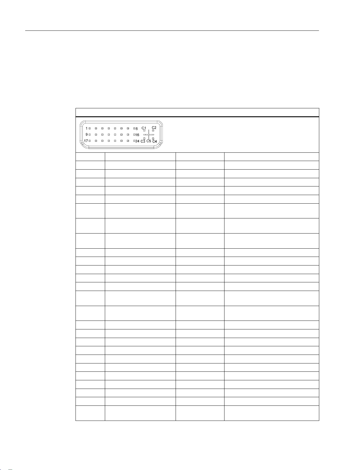
Interfaces
4.8 DVI-I
4.8 DVI-I
Interface assignment
Designation: DVI/VGA, X70
Type: 26-pin socket
DVI-I interface (standard socket)
Pin no. Short description Meaning Input/output
1 TMDS Data2- DVI data channel Output
2 TMDS Data2+ DVI data channel Output
3 TMDS Data2/4 shield Cable shield 4 NC - 5 NC - 6 DDC clock (SCL) Display Data
7 DDC data (SDA) Display Data
8 Analog vertical sync
9 TMDS Data1- DVI data channel Output
10 TMDS Data1+ DVI data channel Output
11 TMDS Data1/3 shield Cable shield 12 NC - 13 NC - 14 +5 V power (VCC) +5 V power for
15 Ground (return for +5 V,
16 Hot Plug Detect - 17 TMDS data 0- DVI data channel Output
18 TMDS data 0+ DVI data channel Output
19 TMDS Data0/5 shield Cable shield 20 NC - 21 NC - 22 TMDS clock shield Cable shield 23 TMDS clock+ DVI clock channel Output
24 TMDS clock- DVI clock channel Output
C1 Analog red (R) Analog red signal Output
C2 Analog green (G) Analog green sig‐
(VSYNC)
Hsync and Vsync) (GND)
Channel – Clock
Channel – Data
Analog Vertical
Sync Signal
DCC
Analog ground -
nal
Input/output
Input/output
Output
Output
Output
SIMOTION P320-4 E / P320-4 S
56 Manual, 01/2015
Page 57

DVI-I interface (standard socket)
C3 Analog blue (B) Analog blue signal Output
C4 Analog horizontal sync
(HSYNC)
C5 Analog ground (analog R,
G, & return) (GND)
Analog horizontal
sSync signal
Analog ground -
Output
Interfaces
4.8 DVI-I
SIMOTION P320-4 E / P320-4 S
Manual, 01/2015 57
Page 58

Interfaces
4.9 USB 3.0
4.9 USB 3.0
Interface assignment
Designation: USB X60, ports: P1, P2, P3, P4
Type: 9-channel
USB 3.0 interface
Pin no. Short description Meaning Input/output
1 VBUS + 5 V (fused) Output
2 D- Data line Input/output
3 D+ Data line Input/output
4 GND Ground –
5 RX- Data line Input
6 RX+ Data line Input
7 GND Ground –
8 TX- Data line Output
9 TX+ Data line Output
high current
SIMOTION P320-4 E / P320-4 S
58 Manual, 01/2015
Page 59

4.10 CFast card
Pin assignment for the CFast card interface
Pin no. Short description Meaning
S1 SGND Signal GND (ground for signal integrity)
S2 A+ SATA differential
S3 A- SATA differential
S4 SGND Signal GND (ground for signal integrity)
S5 B- SATA differential
S6 B+ SATA differential
S7 SGND Signal GND (ground for signal integrity)
PC1 CDI Card Detect Out
PC2 GND Device GND
PC3 TBD TBD (not connected)
PC4 TBD TBD (not connected)
PC5 TBD TBD (not connected)
PC6 TBD TBD (not connected)
PC7 GND Device GND
PC8 LED1 LED Output (not connected)
PC9 LED2 LED Output (not connected)
PC10 IO1 Reserved Input/Output (not connected)
PC11 IO2 Reserved Input/Output (not connected)
PC12 IO3 Reserved Input/Output (not connected)
PC13 PWR Device Power (3.3V)
PC14 PWR Device Power (3.3V)
PC15 GND Device GND
PC16 GND Device GND
PC17 CDO Card Detect In
Interfaces
4.10 CFast card
SIMOTION P320-4 E / P320-4 S
Manual, 01/2015 59
Page 60

Interfaces
4.11 COM1
4.11 COM1
Serial interface COM1, 9-pin (connector)
Pin no. Short description Meaning Input/output
1 DCD Data carrier detect Input
2 RxD Receive data Input
3 TxD Transmit data Output
4 DTR Data terminal ready Output
5 GND Ground 6 DSR Data set ready Input
7 RTS Request to send Output
8 CTS Clear to send Input
9 RI Incoming call Input
SIMOTION P320-4 E / P320-4 S
60 Manual, 01/2015
Page 61

4.12 IsoPROFIBUS board (optional)
PROFIBUS interface, 9-pin (socket)
Pin no. Short description Meaning
1-2 NC Not connected
3 LTG_B Data line (I/O)
4 RTS_AS Turn on PLC transmitter (O)
5 GND Ground isolated
6 P5V_dp_fused +5 V / max. 90 mA (fused) electrically isolated
7 NC Not connected
8 LTG_A Data line (I/O)
9 RTS_PG PG Request to send (O)
Interfaces
4.12 IsoPROFIBUS board (optional)
SIMOTION P320-4 E / P320-4 S
Manual, 01/2015 61
Page 62

Interfaces
4.12 IsoPROFIBUS board (optional)
SIMOTION P320-4 E / P320-4 S
62 Manual, 01/2015
Page 63

Installation/mounting
5.1 Installing the device
SIMOTION P320-4 is particularly suitable for installation in consoles, control cabinets and
switchboards.
WARNING
Perform function test while installing the device in machines or plants
Following the results of a risk analysis, additional protection equipment on the machine or
system is necessary to avoid endangering persons. With this, especially the programming,
the
configuration and wiring of the inserted I/O modules have to be executed, in accordance with
the necessary risk analysis identified safety performance (SIL, PL or Cat.). The intended use
of the device has to be secured.
The correct use of the device has to be verified with a function test on the system. This test
can detect programming, configuration and wiring errors. The test results have to be
documented and if necessary inserted into the relevant inputs.
5
SIMOTION P320-4 E / P320-4 S
Manual, 01/2015 63
Page 64

Installation/mounting
5.2 Permissible mounting positions
5.2 Permissible mounting positions
Note
The SIMOTION P320-4 is approved for operation in closed rooms only.
Ensure the required minimum clearance to other components or enclosure panels:
● Below at least 100 mm
● Above at least 50 mm
The permissible mounting positions for the SIMOTION P320-4 are standard rail mounting and
vertical mounting.
Standard rail mounting
Horizontal mounting is the preferred position.
The following horizontal mounting option is permitted:
The interfaces are at the bottom.
The figure shows the interfaces on the front for
representation purposes only.
For rail mounting, the interfaces always point
downward.
You can find mounting information under Standard rail mounting (Page 65).
SIMOTION P320-4 E / P320-4 S
64 Manual, 01/2015
Page 65

Vertical mounting
Installation/mounting
5.2 Permissible mounting positions
The following vertical mounting option is permitted:
The interfaces are at the front. The power sup‐
ply connection is at the top.
You can find information on mounting under Vertical mounting (Page 67).
Ambient conditions
Observe the permissible temperature range for operation in the respective mounting position
as described in Section "
Technical data > Ambient conditions (Page 90)".
5.2.1 Standard rail mounting and vertical mounting
5.2.1.1 Standard rail mounting
Requirement
● Standard mounting rail, 35 mm standard profile
The standard mounting rail is installed at the installation site.
● The standard mounting rail clip is attached to the SIMOTION P320-4.
Note
Ensure that the wall or ceiling can hold four times the total weight of the SIMOTION P320-4
including the standard mounting rail and additional expansion cards. See section
installation (Page 69).
Notes on
SIMOTION P320-4 E / P320-4 S
Manual, 01/2015 65
Page 66

Installation/mounting
5.2 Permissible mounting positions
Mounting the standard mounting rail clip
Before you can install the device on a standard mounting rail, you will need to attach the
standard mounting rail clip included in the scope of delivery.
The fasteners and screws required are supplied with the device for mounting depending on
the order number.
Requirement
1 standard mounting rail clip
●
● 2 screws
● 1 T20 screwdriver
Use the two screws to mount the standard mounting rail clip on the SIMOTION P320-4
enclosure.
Figure 5-1 Mounting the standard mounting rail clip
SIMOTION P320-4 E / P320-4 S
66 Manual, 01/2015
Page 67

Mounting
1. Place the SIMOTION P320-4 and rail clip on the
upper
edge of the standard profile rail at the po‐
sition shown.
2. Press the SIMOTION P320-4 slightly down‐
ward.
3. Once the rail clip slides over the bottom edge of
standard mounting rail, push the device onto
the
the rail.
Ensure that you hear the SIMOTION P320-4
snapping into place.
Installation/mounting
5.2 Permissible mounting positions
Note
To ensure secure vertical mounting on standard mounting rails, install a standard rail ground
terminal beneath the device.
Removing
1.
Press the SIMOTION P320-4 down until the rail clip releases the device.
2. Swing the SIMOTION P320-4 away from the standard mounting rail.
3. Lift the device up and off.
5.2.1.2 Vertical mounting
The fasteners and screws required are supplied with the device for the selected mounting
option.
Requirement
● 2 mounting brackets
● 4 screws
● 1 T20 screwdriver
SIMOTION P320-4 E / P320-4 S
Manual, 01/2015 67
Page 68

Installation/mounting
5.2 Permissible mounting positions
Procedure
1. Secure each mounting bracket with two
screws.
SIMOTION P320-4 E / P320-4 S
68 Manual, 01/2015
Page 69

5.3 Installation notes
Note the following:
●
The SIMOTION P320-4 is approved for operation in closed rooms only.
● For installation in a control cabinet, observe the SIMATIC installation guidelines and
applicable DIN/VDE requirements or other applicable country-specific regulations.
● When the device is used in the area of Industrial Control Equipment according to UL508,
note that the device is classified as "Open Type". The installation of the device in a housing
according to UL508 is therefore a mandatory requirement for approval or operation in
according to UL508.
Securely fastening the SIMOTION P320-4
NOTICE
Insufficient load carrying capacity
If the wall it is mounted on does not have a sufficient load-bearing capacity, the device may
fall and be damaged.
Installation/mounting
5.3 Installation notes
Ensure
including fixing elements.
NOTICE
Incorrect fixing elements
The
below for mounting. The device can fall and may be damaged.
Use only the dowels and screws specified in the following table.
that the mounting surface on the wall can bear four times the total weight of the device,
device may not be securely fitted if you use dowels and screws other than those specified
SIMOTION P320-4 E / P320-4 S
Manual, 01/2015 69
Page 70

Installation/mounting
5.3 Installation notes
Connecting elements
The connecting elements for each mounting position are listed in the following:
●
● Vertical mounting
Standard rail mounting
Material Bore diameter Fastener
Metal,
min. 2 mm thickness
Concrete 6 mm, 40 mm depth
Plasterboard,
min. 13 mm thickness
Material Bore diameter Fastener
Concrete 6 mm, 40 mm depth
Plasterboard,
min. 13 mm thickness
5 mm
14 mm 4 x toggle bolts, ∅
8 mm, 40 mm depth
14 mm Toggle bolt, ∅ 4 mm, 50 mm length
● 2 x M4 screws
●
2 x M4 nuts
● 4
● 4 x screws, ∅ 4 mm, 40 mm length
● 4
● 4 x screws, ∅ 4 mm, 40 mm length
● Dowel, ∅ 8 mm, 40 mm length
● Screw, ∅ 5 mm, 40 mm length
x dowels, ∅ 6 mm, 40 mm length
4 mm, 50 mm length
x dowels, ∅ 6 mm, 40 mm length
Mounting positions
The following mounting positions are permitted for the SIMOTION P320-4 and are described
in detail in the following sections:
●
Standard rail mounting (Page 65)
● Vertical mounting (Page 67)
SIMOTION P320-4 E / P320-4 S
70 Manual, 01/2015
Page 71

Installation/mounting
5.4 Overview of operating modes for the SIMOTION P320-4
5.4 Overview of operating modes for the SIMOTION P320-4
Overview
The following operating modes are available for mounting the SIMOTION P320-4.
The operating modes are:
●
Decentralized structure
The SIMOTION P320-4 is mounted separately from a panel in a decentralized structure.
● Headless operation
The SIMOTION P320-4 is operated without panel.
Before mounting, the following must be noted:
Before you mount the SIMOTION P320-4 in a control cabinet or a rack, optional components
are installed to expand the SIMOTION P320-4.
Example: installation of the optional IsoPROFIBUS board.
To do this, open the device and note the following procedure:
1. Open the cover of the SIMOTION P320-4.
2. Insert the optional IsoPROFIBUS board.
3. Plug in the SYNC I/O cable for synchronizing with PROFINET.
4. Close the cover.
5. Mount the SIMOTION P320-4.
Note
The
installation and removal of components as well as the mounting of the SIMOTION P320-4
are described in detail in the SIMOTION P320-4 E / P320-4 S Commissioning and Hardware
Installation Manual.
NOTICE
Avoid loss of warranty
you install or exchange system expansions and damage your device, the warranty becomes
If
void.
SIMOTION P320-4 E / P320-4 S
Manual, 01/2015 71
Page 72

Installation/mounting
5.5 Decentralized structure
5.5 Decentralized structure
Overview
The decentralized structure provides greater flexibility in terms of location and enables the
SIMOTION P320-4 to be positioned in non-critical areas of the plant (e.g. control cabinet).
The decentralized structure of a panel with the SIMOTION P320-4 can be performed via the
display
panel.
For the use of an HMI system, the SIMATIC IFP, for example, can be connected by means of
the described interfaces.
port, USB or DVI connection. Please note the cable lengths that are supported for the
SIMOTION P320-4 E / P320-4 S
72 Manual, 01/2015
Page 73

Connection
6.1 Requirements
General information
During the configuration of SIMOTION modules, you must pay attention to the "Electrical
configuration design".
following section provides information on wiring and networking the complete SIMOTION
The
system.
Further information about the connection of the complete system and the individual
components can be found in the SIMOTION P320-4 E / P320-4 S Commissioning and
Hardware Installation Manual
Open equipment
These modules are open equipment. This means they may only be installed in housings,
cabinets, or in electrical equipment rooms that can only be entered or accessed with a key or
tool. Housings, cabinets, or electrical equipment rooms may only be accessed by trained or
authorized personnel. An external fire-protection housing is required.
6
.
Observe the following points during installation:
● The device should be connected only to 24 VDC power supply networks that meet the
requirements of safety extra-low voltage (SELV). The cable cross-section must be chosen
large enough to ensure that no damage can result from cable overheating in the event of
a short-circuit in the SIMOTION P320-4.
● Avoid extreme ambient conditions.
● Protect the device against dust, moisture, heat and severe vibration.
● Do not subject the SIMOTION P320-4 to direct sunlight.
● Install the device in such a way that it poses no danger, for example, by falling over.
● The clearance around the SIMOTION P320-4 must be at least 100 mm to ensure adequate
ventilation.
● Do not cover the ventilation slots.
SIMOTION P320-4 E / P320-4 S
Manual, 01/2015 73
Page 74

Connection
6.2 Overview of connections
6.2 Overview of connections
The connection overview shows the SIMOTION P320-4 interfaces to which the appropriate I/
O devices can be connected.
Note
The cabling for all elements and components of the complete system can only be carried out
when disconnected from the mains.
It does not matter in which order connection takes place.
The connection of the individual components in the SIMOTION P320-4 E / P320-4 S
Commissioning and Hardware Installation Manual.
SIMOTION P320-4 E / P320-4 S
74 Manual, 01/2015
Page 75

7)7PRQLWRU
7)7PRQLWRU
'9,9*$
;
'LVSOD\SRUW
DOWHUQDWLYH
DOWHUQDWLYH
352),1(7GULYHV
HJ6,1$0,&66
352),1(7b,2
HJ(763
+0,3*(6
352),1(7
352),1(7
352),1(7
2QERDUG
(WKHUQHW
+0,3*(6
(WKHUQHW
.H\ERDUGDQG
0RXVH
86%
;
352),%86'3
352),1(7GULYHV
H
J6,1$0,&66
352),1(7b,2
HJ(763
+0,3*(6
352),1(7RQERDUGFRQWUROOHU
+0, +XPDQ0DFKLQH,QWHUIDFH
3* 3URJUDPPLQJ'HYLFH
(6 (QJLQHHULQJ6\VWHP
6HULDO
,QWHUIDFH
%XIIHUHG
65$0
5HWDLQGDWD
352),%86'3
ืP0EDXG
,VR352),%86ERDUGRSWLRQDO
$QDORJ,2PRGXOHV
$',GULYHLQWHUIDFH
6,0$7,&(7
HJ(763
352),%86'3
'ULYHV
6,0$7,&(7
HJ(763
$QDORJ,2PRGXOHV
$',GULYHLQWHUIDFH
352),%86GULYHV
HJ6,1$0,&66
6<1&,2FRQQHFWLQJFDEOH
3DQHOV
3DQHOV
;
;
;
;
6,027,213
Connection
6.2 Overview of connections
Figure 6-1 Hardware system overview - example with PROFINET onboard and optional
IsoPROFIBUS board
SIMOTION P320-4 E / P320-4 S
Manual, 01/2015 75
Page 76

Connection
6.3 Notes on connecting
6.3 Notes on connecting
WARNING
Risk of fire and electric shock
The On/Off switch does not isolate the device from the power supply. Risk of electric shock
if the device is opened incorrectly or defective. There is also a risk of fire if the device or
connecting lines are damaged.
You should therefore protect the device as follows:
Always pull out the power plug when you are not using the device or if the device is
●
defective. The power plug must be freely accessible.
● Connect the device to a protective conductor as instructed, see Section "Connecting the
protective conductor".
● Use a central isolating switch in the case of cabinet installation.
WARNING
Risk of lightning strikes
A lightning strike may enter the mains cables and data transmission cables and reach to a
person.
Death, serious injury and burns can be caused by lightning.
Take the following precautions:
Disconnect the device from the power supply in good time when a thunderstorm is
●
approaching.
● Do not touch mains cables and data transmission cables during a thunderstorm.
● Keep a sufficient distance from electric cables, distributors, systems, etc.
NOTICE
Fault caused by I/O devices
The connection of I/O devices can cause faults in the device.
The result may be personal injury and damage to the machine or plant.
Note the following when connecting I/O devices:
● Read the documentation of the I/O devices. Follow all instructions in the documentation.
● Only connect I/O devices which are approved for industrial applications in accordance
with EN 61000-6-2 and IEC 61000-6-2.
● I/O devices that are not hotplug-capable may only be connected after the device has been
disconnected from the power supply.
SIMOTION P320-4 E / P320-4 S
76 Manual, 01/2015
Page 77

Connection
6.3 Notes on connecting
NOTICE
Damage through regenerative feedback
Regenerative feedback of voltage to ground by a connected or installed component can
damage the device.
Connected
or built-in I/Os, for example, a USB drive, are not permitted to supply any voltage
to the device. Regenerative feedback is generally not permitted.
SIMOTION P320-4 E / P320-4 S
Manual, 01/2015 77
Page 78

Connection
6.4 Protective conductor connection and potential equalization
6.4 Protective conductor connection and potential equalization
The protective conductor connection is needed to protect the device and helps ensure that
interference signals generated by power lines, signal lines or lines to I/O devices are safely
discharged to earth.
The protective conductor connection on the device must be connected to the protective
conductor of the control cabinet or system in which the device is installed.
WARNING
Electrical shock hazard and risk of fire
Internal components of a faulty device may carry dangerous voltages that pose the risk of
fire or electrical shock. Risk of death and serious injury.
Always connect the ground conductor before you commission the device.
●
● Never operate the device without protective conductor.
● Take a faulty device out of service immediately and mark it accordingly.
Requirement
The device has been installed.
●
● 1 protective conductor, minimum cross section 2.5 mm
● 1 T20 screwdriver
● 1 x M4 cable lug
2
SIMOTION P320-4 E / P320-4 S
78 Manual, 01/2015
Page 79

Procedure
6.4 Protective conductor connection and potential equalization
Crimp the cable lug onto the protective conductor.
1.
2. Screw the cable lug onto the protective conductor connection as shown.
Connection
① Protective conductor connection / potential equalization
3. Wire
the protective conductor to the protective conductor connection of the control cabinet
in which the device is installed.
SIMOTION P320-4 E / P320-4 S
Manual, 01/2015 79
Page 80

Connection
6.5 Connecting peripheral equipment
6.5 Connecting peripheral equipment
Note
Observe suitability for industrial applications
Only connect I/O devices that are suitable for industrial applications in accordance with
EN IEC 61000-6-2.
Note
I/O devices capable of hot-plugging (USB)
Hot-plug I/O devices (USB) may be connected while the PC is in operation.
NOTICE
Non-hot-plug I/O devices
devices that do not support hot-plugging may not be connected until the device is powered
I/O
down. Strictly adhere to the specifications for peripheral equipment.
Note
Wait at least ten seconds before you reinsert USB devices.
that the EMC immunity of standard USB devices is designed only for office environments.
Note
These USB devices are appropriate for handling commissioning and service tasks. You may
only use USB devices that are suitable for industrial applications. The USB devices are
developed and marketed by the respective supplier. The respective product supplier provides
support for the USB devices. The manufacturer's terms of liability shall apply.
Note
The connected or built-in I/Os, such as USB drives, should not introduce a counter EMF into
the device.
Reverse voltages exceeding 0.5 V to ground that are generated by connected or installed
components may prevent proper operation of the device or lead to its destruction.
SIMOTION P320-4 E / P320-4 S
80 Manual, 01/2015
Page 81

6.6 Connecting the power supply (24 VDC)
Please note the following to ensure you operate the device safely and in accordance with
regulations:
WARNING
Electrical shock hazard and risk of fire
Voltage exceeding SELV levels may cause fire or electric shock. Death or serious physical
injury can result.
Always wire the device to a 24 VDC power supply that is compliant with SELV
●
requirements.
● You need a corresponding NEC Class 2 power source to comply with requirements to UL
50950-1 and UL 508 when operating the device on a wall, in an open frame, or at any
other location.
● In all other cases (IEC / EN / DIN EN 60950-1), either a current source of limited output
(LPS = Low Power Source), or a line-side fuse or a line-side circuit breaker is necessary.
Current must be limited to 4.16 A. This requires a 4 A fuse max.
Connection
6.6 Connecting the power supply (24 VDC)
Requirement
The device has reverse polarity protection.
The device has been installed.
●
● The protective conductor is connected.
● One wired terminal.
The corresponding 24 VDC power supply is off.
● One 0.5 × 3 Philips screwdriver.
NOTICE
Damage to the device
Do not turn the screws of the terminal when the terminal is inserted in the device. The device
can be damaged through the pressure of the screwdriver on the terminal and consequently
the connection socket.
Only connect the wires to the terminal when it is unplugged.
Note
sure that the wires are not accidentally swapped over. Note the labeling for the contacts
Make
on the front cover of the device.
The terminal to connect the power supply is attached to the device. The terminal is designed
for
wires with a cross-section of 0.25 mm² to 2.5 mm². Only connect wires with a cross-section
≥ 0.5 mm².
Solid or flexible cables can be used for the connection. Ferrules are not required.
SIMOTION P320-4 E / P320-4 S
Manual, 01/2015 81
Page 82

*1'
9b'&
Connection
6.6 Connecting the power supply (24 VDC)
Procedure
1. Connect the cables as shown.
Note the position of the terminal.
2. Insert the terminal at the marked po‐
sition.
3. Secure the terminal using the integra‐
ted screws.
SIMOTION P320-4 E / P320-4 S
82 Manual, 01/2015
Page 83

6.7 Connecting the device to networks
Ethernet can be used for integrating the device into existing or planned networks.
Ethernet
The
integrated Ethernet interface can be used for communication and for data exchange with
automation devices such as SIMOTION SCOUT, SIMATIC S7.
You will need SIMOTION SCOUT, STEP 7, WinCC, WinCC flexible, WinAC and
SIMATIC NET.
Further information
Further information is available on the Internet at the Siemens Industry Mall
(
www.siemens.com/industrymall),
the catalog and ordering system for automation and drives.
Connection
6.7 Connecting the device to networks
SIMOTION P320-4 E / P320-4 S
Manual, 01/2015 83
Page 84

Connection
6.8 Installing the strain relief
6.8 Installing the strain relief
Strain relief for the device is provided in the scope of delivery. The strain relief is designed to
prevent the lines connected to the device from being accidentally pulled out.
Attaching PROFINET strain relief
Requirement
●
1 strain relief
● 2 screws
● 1 T10 screwdriver
Mounting
1. Remove the marked countersunk
screws.
2. Fasten the strain relief at the PROFI‐
NET interface(s).
Use the oval head screws included
with the strain relief.
Removing
Follow the mounting procedure in reverse to remove the strain relief.
Securing cables generally
Secure
cable ties are not part of the scope of delivery.
Requirement
● Maximum of 6 cable ties for USB, Ethernet, PROFIBUS
Maximum cable tie width 3 mm.
● 1 cutting tool
Procedure
1. Place the cable tie around the attachment plate of the strain-relief assembly and secure
the plugged-in cables.
2. Cut off the cable tie overhang.
all cables connected to the device at the cable grip, each with a cable tie. The required
SIMOTION P320-4 E / P320-4 S
84 Manual, 01/2015
Page 85

Troubleshooting/FAQs
7.1 Error correction
section provides you with tips on how to locate and troubleshoot common problems.
This
FAQs / error correction Possible cause To correct or avoid error
The device is not opera‐
tional.
The monitor remains dark. The monitor is switched
The mouse pointer does
not appear on the screen.
Wrong time and/or date
on the PC.
Although the BIOS setting
is OK, the time and date
are still wrong.
USB device not respond‐
ing.
There is no power supply
to the device.
off.
The monitor is in "power‐
save" mode.
The brightness button has
been set to dark.
The power cord or the
monitor cable is not con‐
nected.
The mouse driver is not
loaded.
The mouse is not connec‐
ted.
The backup battery is
empty.
The operating system
does not have a suitable
driver for the USB device.
● Check whether the 24 VDC power supply is connected (see
Connecting the power supply (24 VDC)
● Check whether the line side switch is activated (see Operator
controls (Page 50)).
Switch on the monitor.
Press any key on the connected keyboard.
Set the monitor brightness button to obtain more light.
detailed information, refer to the monitor operating instructions.
For
● Check
● Check whether the monitor cable has been properly connected
If the monitor screen still remains dark after you have performed
these checks, please contact your technical support team.
Check whether the mouse driver is properly installed and present
when
tion, refer to the manuals for the mouse or application programs.
Check whether the mouse is properly connected to the system unit.
you use an adapter or extension on the mouse cable, also check
If
the connectors.
If the mouse pointer still does not appear on the screen after you
have performed these checks and measures, please contact your
technical support team.
● Press <ESC> during the boot sequence to open BIOS Setup.
●
Replace the backup battery.
(See SIMOTION P320-4 E / P320-4 S Commissioning and Hard‐
ware
the back-up battery).
If the problem cannot be resolved by replacing the battery, then
contact your technical support team.
Install a suitable driver; the correct driver can often be downloaded
from the homepage of the device's manufacturer.
whether the power cord has been properly connected to
the monitor and to the system unit or to the grounded shockproof
outlet.
to the system unit and to the monitor.
you start the application program. For more detailed informa‐
Set the time and date in the setup menu.
Installation Manual > Service and maintenances > Replacing
7
(Page 81)).
SIMOTION P320-4 E / P320-4 S
Manual, 01/2015 85
Page 86

Troubleshooting/FAQs
7.1 Error correction
SIMOTION P320-4 E / P320-4 S
86 Manual, 01/2015
Page 87

Technical data
8.1 Overview of the technical specifications
Overview
following technical specifications are available for SIMOTION P320-4 and the associated
The
hardware components:
● General SIMOTION P320-4 technical specifications (Page 88)
● Ambient conditions (Page 90)
– Climatic conditions
– Mechanical conditions
● Technical specifications of the IsoPROFIBUS board (Page 92)
● Power requirement of the components (Page 94)
● Integrated DC voltage supply (Page 95)
● Technical specifications of the SITOP smart 24 V / 10 A (Page 96)
● Typical power consumption (Page 98)
8
SIMOTION P320-4 E / P320-4 S
Manual, 01/2015 87
Page 88

Technical data
8.2 General technical specifications
8.2 General technical specifications
General technical specifications
General technical specifications for SIMOTION P320-4
Article numbers SIMOTION P320-4 E
●
SIMOTION P320-4 S
● 6AU1320-4DS66-3AG0
Dimensions 262 × 133 × 50.5 (W × H × D in mm)
Weight Approximately 2 kg
Supply voltage (DC)
1
24 VDC 1 (-20%/+20%)
6AU1320-4DE65-3AF0
Short-term voltage interruption in accord‐
ance with Namur
Max. power consumption 64.8 W (at 24 V)
Degree of protection IP 20 according to IEC 60529
Protection class Protection class I according to IEC 61140
Safety regulations EN 60950-1; UL 60950-1; UL 508;
Noise emission <40dB (A) to DIN 45635-1
Quality assurance In accordance with ISO 9001
1
The upstream power supply must generate a safety extra-low voltage with safe electrical
isolation
UL/EN/ DIN-EN 60950-1 (see the section "Connecting the power supply (24 V DC)
(Page 81)").
Electromagnetic compatibility
Electromagnetic compatibility
Interference emission EN 61000-6-3, EN 61000-6-4, CISPR220 class B; FCC class A
Immunity with regard to conducted
interference on the supply lines
Noise immunity on signal lines ± 1 kV according to IEC 61000-4-4; burst; length < 3 m
Immunity to electrostatic discharge ± 6 kV contact discharge according to IEC 61000-4-2
Immunity to RF interference 10 V/m 80–1000 MHz and 1.4–2 GHz, 80% AM according to
Immunity to magnetic fields 100 A/m, 50/60 Hz according to IEC 61000-4-8
Min. 15 ms (at 20.4 V)
Max. 10 events/h; recovery time min. 1 s
according to IEC 60364-4-41 or an NEC Class 2 SELV and LPS according to IEC/
± 2 kV according to IEC 61000-4-4; burst
± 1 kV according to IEC 61000-4-5; symmetrical surge
± 2 kV according to IEC 61000-4-5; asymmetrical surge
± 2 kV according to IEC 61000-4-4; burst; length > 3 m
± 2 kV according to IEC 61000-4-5; surge; length > 30 m
± 8 kV air discharge according to IEC 61000-4-2
IEC 61000-4-3
1 V/m 2–2.7 GHz, 80% AM according to IEC 61000-4-3
10 V 10 kHz to 80 MHz, 80% AM according to IEC 61000-4-6
SIMOTION P320-4 E / P320-4 S
88 Manual, 01/2015
Page 89

Motherboard
Motherboard
Processor
Main memory 4 GB
Buffer memory
Drive and memory media
Drive and memory media
Solid State Disk (SSD) ≥ 80 GB Standard (SIMOTION P320-4 S)
CFast card ≥ 4 GB
Graphics
Graphics
Graphics controller Integrated Intel HD2000 or HD4000
Graphics memory 32 - 512 MB Shared Memory
Resolutions, frequencies, color
depth
Technical data
8.2 General technical specifications
● Intel
● Intel Core i7-3517UE 1.7 GHz, 4 MB SLC (SIMOTION P320-4 S)
512 KB MRAM
Core i3-3217UE 1.6 GHz, 3 MB SLC (SIMOTION P320-4 E)
DVI-I: 640 × 480 to 1920 × 1200 / 60 Hz
Display port: max. 1920 ×1200 / 60 Hz
Interfaces
Interfaces
COM1 RS232, 115 kbps max., 9-pin SUB-D, male
DVI-I Connection of display devices with DVI connector
Display port (DPP) Connection of display devices with DPP connector
Keyboard USB support
Mouse USB support
USB 4 × USB 3.0
PROFINET 3 × RJ45 connector, onboard interface on ERTEC 400 basis, 100
Mbps electrically isolated
Ethernet 1 × Ethernet interface (RJ45)
10/100/1000 Mbps, electrically isolated, with teaming function
SIMOTION P320-4 E / P320-4 S
Manual, 01/2015 89
Page 90

Technical data
8.3 Ambient conditions
8.3 Ambient conditions
Climatic conditions
Temperature Tested according to IEC 60068-2-1, IEC 60068-2-2, IEC 60068‑2‑14
- During operation
- During storage/shipping -40 °C to +70 °C (for devices with CFast or SSD)
- Gradient Operating mode: Max. 10° C/h; Storage: 20° C/h; no condensation
Relative humidity
- During operation
- During storage/shipping
Air pressure
- During operation
- During storage/shipping
1
For P320-4 S you must set "Turbo Mode Level" to "Temperature optimized" in the "Power" menu,
selection "Advanced CPU Control", of the BIOS Setup; otherwise you have to reduce the maximum
ambient temperature by 5 °C.
2
RAL = Restricted Access Location
Installation
of device in operating facilities with restricted access, for example, a locked control cabinet.
Standard rail mounting (preferred mounting position):
Operation with CFast card and/or SSD:
●
With max. 1 expansion card
(max. load 10 W): 0 to +40° C
● With max. 1 expansion card
(max. load 10 W) in RAL 2: 0 to +50° C
1
Operation with CFast card:
● Without expansion cards in RAL 2: 0 to +55° C
1
Vertical mounting:
Operation with CFast card and/or SSD:
Without expansion cards: 0 to +40° C
●
Operation with SSD:
● With max. 1 expansion card
(max. load 10 W) in RAL 2: 0 to +45° C
1
Operation with CFast card:
● Without expansion cards
in RAL 2: 0 to +50° C
1
● With max. 1 expansion card
(max. load 10 W): 0 to +40° C
● With max. 1 expansion card
(max. load 10 W) in RAL 2: 0 to +50° C
1
Tested according to IEC 60068-2-78, IEC 60068-2-30
5% to 80% at 25° C (no condensation)
5% to 95% at 25° C (no condensation)
1080 to 795 hPa
(corresponds to an altitude of -1000 m to 2000 m)
1080 to 660 hPa
(corresponds to an altitude of -1000 m to 3500 m)
SIMOTION P320-4 E / P320-4 S
90 Manual, 01/2015
Page 91

Mechanical conditions
Vibration Tested according to DIN IEC 60068-2-6
- During operation With CFast card or SSD:
- During storage/shipping 5 to 9 Hz: 3.5 mm
Resistance to shock Tested according to DIN IEC 60068-2-27
- During storage/shipping 250 m/s2, 6 ms
Technical data
8.3 Ambient conditions
5 to 9 Hz: 3.5 mm
9 to 500 Hz: 9.8 m/s2
9 to 500 Hz: 9.8 m/s2
SIMOTION P320-4 E / P320-4 S
Manual, 01/2015 91
Page 92

Technical data
8.4 Technical data of the IsoPROFIBUS board
8.4 Technical data of the IsoPROFIBUS board
Technical specifications of the IsoPROFIBUS board (optional)
Table 8-1
IsoPROFIBUS board
Power consumption for + 5 V PCI voltage
Standard 2.5 W
Maximum 3.5 W
Permissible ambient conditions
Heat dissipation Open circuit ventilation
Temperature Operation Storage/transport
● IsoPROFIBUS board in the
SIMOTION P320-4
Tested according to EN 60068-2-1, EN 60068-2-2, EN 60068-2-14
Relative atmospheric humidity Operation Storage/transport
● IsoPROFIBUS board in the
SIMOTION P320-4
Tested according to EN 60068-2-30
Temperature change Max. 10 K per hour in operation
Moisture condensation and ice formation Not permissible
Design
Module Card (3.3 V/5 V, 32 bits)
Dimensions (H x D) in mm 107 x 170
Weight 150 g
Space requirements Short PCI slot
5° C to 45° C -20° C to 60° C
5 % … 80 % 5 % … 95 %
Safety
Safety
Degree of protection IP20 in mounted state
Protection class I complies with VDE 0106
Safety regulations EN 60950
Approvals CE, UL508, cULus
SIMOTION P320-4 E / P320-4 S
92 Manual, 01/2015
Page 93

Quality assurance
Technical data
8.4 Technical data of the IsoPROFIBUS board
Quality assurance complies with ISO 9001.
Note
The safety regulations, approvals, protection type and protection class specified are valid only
if the module is inserted in a SIMOTION P320-4.
SIMOTION P320-4 E / P320-4 S
Manual, 01/2015 93
Page 94

Technical data
8.5 Power requirements of the components
8.5 Power requirements of the components
Maximum power consumption of the auxiliary components
Auxiliary components Maximum permitted power con‐
sumption
+5 V +3.3 V +12 V
USB device High current 900 mA - - 10 W (for all USB devices)
Display port - 500 mA -
DVI-I 500 mA - -
PROFIBUS 500 mA - -
PCI modules Per slot - 1.5 A 0.5 A 10 W (for entire device)
Total - 2 A 1 A
1
The total power of the PCI and USB cards may not exceed 15 W
Max. total power
Note
Device can overheat!
To avoid overheating, the power loss per PCI slot should not exceed 5 watts.
SIMOTION P320-4 E / P320-4 S
94 Manual, 01/2015
Page 95

8.6 Integrated DC power supply
Technical specifications
DC power supply
Input voltage 24 V DC (-20%/+20%)
Power consumption
Power failure buffering hold-up time = 20 ms at 20.4 V
Maximum continuous output power
Degree of protection IP 20
Protection class Protection class I (a protective conductor must be
1
The power specifications apply to the power supply component not to the device.
Note
Inrush current
1
1
Technical data
8.6 Integrated DC power supply
Max. 90 W
(DC_FAIL is active after > 5 ms)
80 W
connected to the device)
The device requires an inrush current of at least 6.5 A for 50 ms.
The
peak value of the startup current depends on the input voltage and the impedance of the
24 V power source. Peak currents greater than 6.5 A are possible. This will not have a negative
impact on device functionality.
SIMOTION P320-4 E / P320-4 S
Manual, 01/2015 95
Page 96

Technical data
8.7 Technical data for the SITOP smart 24 V/10 A
8.7 Technical data for the SITOP smart 24 V/10 A
Table 8-2
SITOP smart 24 V/10 A
Input data
Input voltage rated value 120/230 VAC
Input voltage range 85 to 132 VAC / 170 to 264 VAC
Power failure bridging > 20 ms at Vin = 93/187 V
Mains frequency rated value 50/60 Hz
Mains frequency range 47 … 63 Hz
Input current rated value 4.1/2.4 A
Switch-on current (at +25° C) < 65 A
Recommended miniature circuit breaker 10 A, Characteristic C
Output data
Output voltage rated value 24 VDC
Output voltage tolerance ± 3 %
Residual ripple/spikes < 150/240 mV
Output voltage adjustment range 22.8 to 28 VDC
Output current rated value 10 A
Efficiency Typ. 90%
Electronic short-circuit protection Yes;
Ambient conditions
Ambient temperature during storage and
transport
Ambient temperature during operation 0° … +60° C
Humidity class Climate class 3K3 according to EN 60721;
Degree of protection (EN 60529) IP20
Radio suppression level (EN 55022) Class B
Line harmonic limitation according to
EN 61000‑3‑2
EMC immunity EN 61000-6-2;
EMC interference emission EN 61000-6-4
Safety
Safety class (IEC 536; VDE 1006 T1) Class I
Primary/secondary galvanic isolation SELV output voltage according to EN 60950 and
Technical specifications for the SITOP smart 24 V / 10 A
pp
(12 A up to +45° C)
constant current approx. 1.3 × output current rated value;
for 5 seconds extra power at 1.5 × output current rated
value
-40° … +85° C
relative atmospheric humidity 5 to 95%; no condensation
No
EN 61000-4-2/-3/-4/-5/-6/-11
EN 50178;
transformer according to EN 61558-2-17;
overvoltage protection in the event of an internal error
Ua < 60 V
SIMOTION P320-4 E / P320-4 S
96 Manual, 01/2015
Page 97

Technical data
8.7 Technical data for the SITOP smart 24 V/10 A
SITOP smart 24 V/10 A
Dimensions and weight
Dimensions (W x H x D) in mm 70 x 125 x 125
Weight Approximately. 0.75 kg
Certifications and approvals
CE CE conformity according to 98/336 EEC and 73/23 EEC
UL/CSA UL 508 (Listed, File E197259);
CSA C22.2 No 14, No 60950-1-03
Shipbuilding Germanischer Lloyd
Directive 94/9/EC Declaration of conformity according to EN 60079‑15:
ATEX94/9/EC Cat.3;Eex, nA, II, T4 U
C‑Tick AS/NZS 2064:1997
Article numbers
6EP1334‑2AA01, 6EP1334‑2BA01
SIMOTION P320-4 E / P320-4 S
Manual, 01/2015 97
Page 98

Technical data
8.8 Typical power consumption
8.8 Typical power consumption
Technical specifications
Typical current and power consumption of the device at a rated voltage of 24 V
Description Current consumption Power consumption
Device with core i3 or core i7 pro‐
cessor
Fieldbus (PROFINET) 120 mA 3 W
USB expansion
PCI expansion
1
The total power of the PCI and USB expansion may not exceed 15 W
1
1
950 mA 23 W
Max. 500 mA Max. 12 W
Max. 500 mA Max. 12 W
SIMOTION P320-4 E / P320-4 S
98 Manual, 01/2015
Page 99

Dimension drawings
9.1 Overview of the dimensional drawings
This section contains the dimension drawings for the SIMOTION P320-4:
Standard rail mounting (Page 100)
●
● Vertical mounting (Page 102)
● SIMOTION P320-4 with an expansion card (Page 105)
9
SIMOTION P320-4 E / P320-4 S
Manual, 01/2015 99
Page 100

262
174
133
Dimension drawings
9.2 Device dimension drawing for standard rail mounting
9.2 Device dimension drawing for standard rail mounting
Various views of the standard rail mounting with dimensions are shown in the following:
Figure 9-1 Standard rail mounting, bottom view
Figure 9-2 Standard rail mounting, front view
SIMOTION P320-4 E / P320-4 S
100 Manual, 01/2015
 Loading...