

Siemens SIMOTION D4 Series, SIMOTION D435, SIMOTION D445, SIMOTION D425 Equipment Manual

SIMOTION D4xx
Equipment Manual
Preface
Introduction
Description
Operator control (hardware)
Interfaces
Technical Data
Dimension drawings
1
2
3
4
5
6
Spare parts/accessories
Appendices
ESD guidelines
7
A
B
12.2004
6AU1900-1AJ32-0BA0
Safety Guidelines
This manual contains notices you have to observe in order to ensure your personal safety, as well as to prevent
damage to property. The notices referring to your personal safety are highlighted in the manual by a safety alert
symbol, notices referring to property damage only have no safety alert symbol. These notices shown below are
graded according to the degree of danger.
Danger
indicates that death or severe personal injury will result if proper precautions are not taken.
Warning
indicates that death or severe personal injury may result if proper precautions are not taken.
Caution
with a safety alert symbol, indicates that minor personal injury can result if proper precautions are not taken.
Caution
without a safety alert symbol, indicates that property damage can result if proper precautions are not taken.
Attention
indicates that an unintended result or situation can occur if the corresponding information is not taken into
account.
If more than one degree of danger is present, the warning notice representing the highest degree of danger will
be used. A notice warning of injury to persons with a safety alert symbol may also include a warning relating to
property damage.
Qualified Personnel
The device/system may only be set up and used in conjunction with this documentation. Commissioning and
operation of a device/system may only be performed by qualified personnel. Within the context of the safety notes
in this documentation qualified persons are defined as persons who are authorized to commission, ground and
label devices, systems and circuits in accordance with established safety practices and standards.
Prescribed Usage
Note the following:
Warning
This device may only be used for the applications described in the catalog or the technical description and only in
connection with devices or components from other manufacturers which have been approved or recommended
by Siemens. Correct, reliable operation of the product requires proper transport, storage, positioning and
assembly as well as careful operation and maintenance.
Trademarks
All names identified by ® are registered trademarks of the Siemens AG. The remaining trademarks in this
publication may be trademarks whose use by third parties for their own purposes could violate the rights of the
owner.
Copyright Siemens AG . All rights reserved.
The distribution and duplication of this document or the utiliz ation and transmission of its
contents are not permitted without express written permission. Offenders will be liable for
damages. All rights, including rights created by patent grant or registration of a utility
model or design, are reserved.
Siemens AG
Automation and Drives
Postfach 4848, 90327 Nuremberg, Germany
Siemens Aktiengesellschaft 6AU1900-1AJ32-0BA0
Disclaimer of Liability
We have reviewed the contents of this publication to ensure consistency with the
hardware and software described. Since variance cannot be precluded entirely, we cannot
guarantee full consistency. However, the information in this publication is reviewed
regularly and any necessary corrections are included in subsequent editions.
Siemens AG 2004
Technical data subject to change

Preface
Contents of manual
This manual describes the SIMOTION D425, D435, and D445 devices.
This document is part of the SIMOTION D documentation package with order number:
6AU1900-1AJ32-0BA0 12.2004 Edition
Scope
This manual is applicable for SIMOTION D425, SIMOTION D435, and SIMOTION D445.
Standards
Contents
The SIMOTION system was developed according to the quality guidelines of ISO 9001.
The following is a description of the purpose and use of the product manual:
• Description
Provides information about the SIMOTION system and its incorporation in the automation
landscape.
• Device Description
Provides information about the structure and architecture of the devices.
• Operator control (hardware)
Provides information about the various operator control and display elements of the devices
as well as the memory concept and Compact Flash Card.
• Interfaces
Provides information about the different interfaces of the devices, their pin assignment, and
possible applications.
• Service and maintenance
Provides information about service and maintenance procedures that must be performed on
the devices.
• Technical Data
• Dimension drawings
• Appendices
Provides information about the various standards and specifications fulfilled by the device.
D4xx
Manual, 12.2004, 6AU1900-1AJ32-0BA0
iii

Preface
Contacts
If you have any problems or questions when using this manual, please contact the office
listed on the reply form at the end of this manual.
Hotline and Web addresses
Hotline
If you have any questions, please contact our hotline (worldwide):
• A & D Technical Support: Phone: +49 (180) 50 50 222
• Fax: +49 (180) 50 50 223
• E-mail: ad.support@siemens.com
If you have any questions, suggestions, or corrections regarding the documentation, please
send them to the following fax number or e-mail address:
• Fax: +49 (9131) 98 2176
• E-mail: motioncontrol.docu@erlf.siemens.de
• Fax form: Refer to the reply form at the end of this manual
Additional support
We also offer introductory SIMOTION courses.
Please contact your regional training center or our main training center at D-90027
Nuremberg/Germany, phone +49 (911) 895 3202.
Siemens Internet address
The latest up-to-date information about SIMOTION products can be found in the Internet
under:
General information http://www.siemens.com/simotion
Technical information http://www4.ad.siemens.de/view/cs/en/10805438
D4xx
iv Manual, 12.2004, 6AU1900-1AJ32-0BA0

Preface
Disposal and recycling
Product disposal
SIMOTION D4xx is an environmentally friendly product. It includes the following features:
• In spite of its excellent resistance to fire, the flame-resistant agent in the plastic used for
the housing does not contain halogens.
• Identification of plastic materials in accordance with DIN 54840
• Less material used due to more compact size, fewer components due to integration in
ASICs. SIMOTION D4xxx is recyclable due to its environmentally compatible materials.
For environmentally friendly recycling and appropriate disposal of your old components,
please contact your local Automation & Drives representative. Contact details can be found
in our contacts database on the Internet at:
http://www3.ad.siemens.de/partner/search.asp
D4xx
Manual, 12.2004, 6AU1900-1AJ32-0BA0
v


Table of contents
Preface ...................................................................................................................................................... iii
1 Introduction............................................................................................................................................. 1-1
1.1 Hardware components............................................................................................................... 1-1
1.2 Product description of D4xx ....................................................................................................... 1-2
1.3 Software components ................................................................................................................ 1-2
1.4 Product variants ......................................................................................................................... 1-3
1.5 System components .................................................................................................................. 1-5
2 Description.............................................................................................................................................. 2-1
2.1 Safety notes ............................................................................................................................... 2-1
2.2 D435 and D425 .......................................................................................................................... 2-2
2.3 D445........................................................................................................................................... 2-3
2.4 Clock .......................................................................................................................................... 2-4
2.5 Power supply of D425 and D435 ............................................................................................... 2-5
2.6 Power supply of D445................................................................................................................ 2-6
3 Operator control (hardware).................................................................................................................... 3-1
3.1 Operator control and display elements ......................................................................................3-1
3.1.1 LED displays .............................................................................................................................. 3-1
3.1.2 Nameplates................................................................................................................................ 3-5
3.1.3 Mode selector............................................................................................................................. 3-7
3.1.4 Reset button............................................................................................................................... 3-8
3.2 SIMOTION CF............................................................................................................................ 3-9
3.2.1 Properties of the CompactFlash card ........................................................................................ 3-9
3.2.2 CompactFlash slot ................................................................................................................... 3-10
3.2.3 Changing the Compact Flash card .......................................................................................... 3-11
3.2.4 Writing to CompactFlash card.................................................................................................. 3-12
3.3 Memory concept ...................................................................................................................... 3-13
3.3.1 Memory concept of SIMOTION D............................................................................................ 3-13
3.3.2 Persistent data (non-volatile data) ........................................................................................... 3-14
3.3.3 Monitoring persistent data (non-volatile data).......................................................................... 3-14
3.3.4 Power off behavior ................................................................................................................... 3-16
4 Interfaces................................................................................................................................................ 4-1
4.1 Interface overview ...................................................................................................................... 4-1
4.2 DRIVE CLiQ interfaces .............................................................................................................. 4-2
4.2.1 DRIVE CLiQ interfaces .............................................................................................................. 4-2
4.2.2 Use of DRIVE CLiQ interface..................................................................................................... 4-3
4.3 Ethernet interfaces ..................................................................................................................... 4-4
D4xx
Manual, 12.2004, 6AU1900-1AJ32-0BA0
vii

Table of contents
4.3.1 Ethernet interfaces X120 and X130 ........................................................................................... 4-4
4.3.2 Use of Ethernet interfaces.......................................................................................................... 4-5
4.4 Digital inputs/outputs.................................................................................................................. 4-6
4.4.1 X122 and X132 digital inputs ..................................................................................................... 4-6
4.4.2 Pin assignment for interfaces X122 and X132........................................................................... 4-8
4.4.3 Technical data for X122 and X132............................................................................................. 4-9
4.4.4 Use of X122 and X123 interfaces ............................................................................................ 4-10
4.5 Power supply............................................................................................................................ 4-11
4.5.1 Power supply X124 .................................................................................................................. 4-11
4.6 PROFIBUS-DP interfaces ........................................................................................................ 4-12
4.6.1 PROFIBUS-DP interfaces X126 and X136 .............................................................................. 4-12
4.6.2 Use of PROFIBUS-DP interfaces ............................................................................................ 4-14
4.7 CompactFlash slot ................................................................................................................... 4-15
4.7.1 Compact Flash slot .................................................................................................................. 4-15
4.8 Measuring sockets ................................................................................................................... 4-15
4.8.1 Measuring sockets X131 - X134 .............................................................................................. 4-15
5 Technical Data........................................................................................................................................ 5-1
5.1 Technical data for D435 and D425 ............................................................................................ 5-1
5.2 Technical data for D445 ............................................................................................................. 5-2
6 Dimension drawings ............................................................................................................................... 6-1
6.1 Dimension drawing of D435 and D425 ...................................................................................... 6-1
6.2 Dimension drawing of D445 ....................................................................................................... 6-2
7 Spare parts/accessories ......................................................................................................................... 7-1
7.1 Fan/battery module .................................................................................................................... 7-1
7.1.1 Cooling the SIMOTION D4xx..................................................................................................... 7-1
7.1.2 Fan/battery module assembly.................................................................................................... 7-2
7.1.3 Battery replacement in the fan/battery module. ......................................................................... 7-3
7.2 Supplemental system components ............................................................................................ 7-4
7.3 Terminal board TB30 ................................................................................................................. 7-5
7.4 Terminal module TM31 .............................................................................................................. 7-5
7.5 Terminal module TM41 .............................................................................................................. 7-6
7.6 Terminal modules TM15 and TM17 High Feature ..................................................................... 7-7
7.7 CX32 module ............................................................................................................................. 7-8
A Appendices.............................................................................................................................................A-1
A.1 Standards................................................................................................................................... A-1
A.2 Information on insulation tests, safety class, and degree of protection .....................................A-1
A.3 Rated voltage for operation of the D4xx ....................................................................................A-2
A.4 Safety of electronic controllers...................................................................................................A-3
A.5 EC Declaration of Conformity.....................................................................................................A-4
B ESD guidelines .......................................................................................................................................B-1
B.1 Electrostatically sensitive modules ............................................................................................ B-1
B.2 Electrostatic accumulation on individuals ..................................................................................B-2
D4xx
viii Manual, 12.2004, 6AU1900-1AJ32-0BA0

Table of contents
B.3 Basic measures for protection against discharge of static electricity ........................................B-3
Index
Tables
Table 1-1
Product variants ......................................................................................................................... 1-3
Table 1-2 Central components................................................................................................................... 1-5
Table 1-3 System components .................................................................................................................. 1-5
Table 1-4 Distributed I/O systems.............................................................................................................. 1-6
Table 1-5 Optional components for the control unit: .................................................................................. 1-6
Table 1-6 Additional components that can be connected to the control unit ............................................. 1-7
Table 2-1 Clock features ............................................................................................................................ 2-4
Table 2-2 Input voltage specification.......................................................................................................... 2-5
Table 2-3 Input voltage specification.......................................................................................................... 2-6
Table 3-1 Meaning of LED states............................................................................................................... 3-2
Table 3-2 Selector positions and their meaning......................................................................................... 3-7
Table 3-3 Mode selector settings ............................................................................................................... 3-8
Table 3-4 Alarm messages of the diagnostics buffer............................................................................... 3-15
Table 4-1 Overview of available external interfaces .................................................................................. 4-1
Table 4-2 Overview of interfaces that cannot be used for SIMOTION D................................................... 4-2
Table 4-3 X100 - X103 or X100 – X105 .....................................................................................................4-2
Table 4-4 DRIVE CLiQ interface (X100 - X103 or X100 – X105) .............................................................. 4-2
Table 4-5 X120 and X130 .......................................................................................................................... 4-4
Table 4-6 Ethernet interfaces (X120, X130, X127) .................................................................................... 4-4
Table 4-7 Interfaces X122 and X132 ......................................................................................................... 4-6
Table 4-8 X122 Digital inputs/outputs ........................................................................................................ 4-8
Table 4-9 Technical data of digital inputs X122/X132................................................................................ 4-9
Table 4-10 Technical data of the digital inputs/output of X122/X132 ........................................................ 4-10
Table 4-11 Interface X124.......................................................................................................................... 4-11
Table 4-12 Power supply X124 .................................................................................................................. 4-11
Table 4-13 Interfaces X126 and X136 .......................................................................................................4-12
Table 4-14 PROFIBUS-DP X126 interface ................................................................................................ 4-13
Table 4-15 PROFIBUS-DP X136 interface ................................................................................................ 4-13
Table 5-1 Memories for user data and their memory size ......................................................................... 5-1
Table 5-2 Electrical connection values....................................................................................................... 5-1
Table 5-3 Dimension and weight of D435 and D425 ................................................................................. 5-1
Table 5-4 Environmental requirements ...................................................................................................... 5-2
Table 5-5 Memories for user data and their memory size ......................................................................... 5-2
D4xx
Manual, 12.2004, 6AU1900-1AJ32-0BA0
ix

Table of contents
Table 5-6 Electrical connection values....................................................................................................... 5-3
Table 5-7 Dimensions and weight of a D445 ............................................................................................. 5-3
Table 5-8 Environmental requirements ...................................................................................................... 5-3
Table 7-1 Overview of TB30 interface........................................................................................................ 7-5
Table 7-2 Interface overview of the TM31.................................................................................................. 7-5
Table 7-3 TM41 interface overview ............................................................................................................ 7-6
Table A-1 Electromagnetic compatibility (EMC) .........................................................................................A-1
Table A-2 Test voltages..............................................................................................................................A-2
Table A-3 Rated voltage for the control unit ............................................................................................... A-2
D4xx
x Manual, 12.2004, 6AU1900-1AJ32-0BA0
Introduction
1.1 Hardware components
SIMOTION runtime module and SINAMICS drive module
As the central hardware, SIMOTION D uses the SIMOTION D4xx as a control unit consisting
of the SIMOTION runtime module and the SINAMICS firmware. The control unit uses the
SINAMICS Integrated drive with various SINAMICS S120 drive modules (line and motor
modules) to perform open-loop and closed-loop control of the axis assembly. In addition, a
series of other SINAMICS 120 components such as SMC encoder systems or terminal
modules can be connected via DRIVE-CLiQ. Likewise, the functionality can be expanded
with distributed I/O via PROFIBUS.
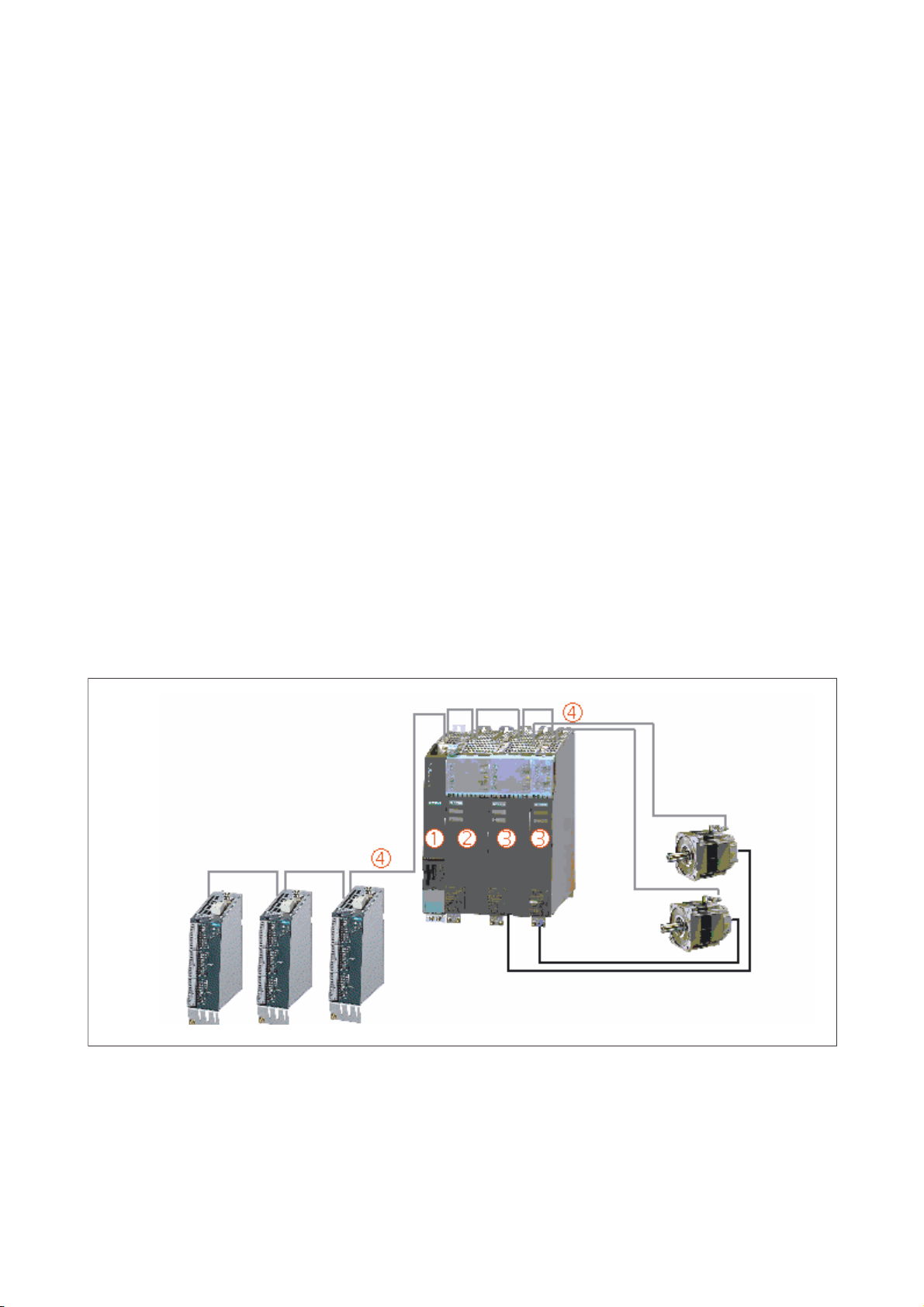
SIMOTION D axis assembly
This illustration shows a typical SIMOTION D axis assembly.
1
'5,9(&/L4
'5,9(&/L4,2
Figure 1-1 Example of a SIMOTION D4xx axis assembly
D4xx
Manual, 12.2004, 6AU1900-1AJ32-0BA0
'5,9(&/L4
3RZHU
1-1

Introduction
1.2 Product description of D4xx
In general, a SIMOTION D axis assembly consists of the following elements:
• SIMOTION D (control unit) (1)
This unit contains the programmable runtime system of SIMOTION and the drive software
of SINAMICS S120. As a general principle, SIMOTION D is capable of controlling multiple
axes/drives.
• SINAMICS infeed (line module) (2)
This module generates a DC link from the supply system.
• SINAMICS power units (motor modules) (3)
These modules are used to control motors.
• DRIVE-CLiQ components (4)
In SINAMICS S120/SIMOTION D, the individual components of the drive system
communicate with each other via DRIVE-CLiQ. In addition to power components, you can
link encoder systems and special DRIVE-CLiQ I/O devices via DRIVE-CLiQ.
1.2 Product description of D4xx
Design of SIMOTION D4xx
SIMOTION D is the drive-based variant of the SIMOTION Motion Control System based on
the new SINAMICS S120 family of drives. With SIMOTION D, the SIMOTION motion control
functionalities and the SINAMICS drive software run on a SINAMICS closed-loop control
hardware device.
As with SINAMICS S120, SIMOTION D subscribes to the Totally Integrated Automation
(TIA) concept, thus providing a comprehensive set of automation blocks.
1.3 Software components
SIMOTION runtime system and SINAMICS closed-loop drive control
The basic functionality of SIMOTION D is furnished with a Compact Flash card and includes
the following:
SIMOTION runtime system including the following functions:
• User-programmable runtime system (IEC 61131)
• Various runtime levels
• Logic and arithmetic functionality
• Communication functions
Motion control functions are available in the form of optional technology packages.
D4xx
1-2 Manual, 12.2004, 6AU1900-1AJ32-0BA0

Introduction
1.4 Product variants
SINAMICS S120 closed-loop drive control including the following functions:
• Closed-loop current and torque control
• Closed-loop speed control
• Regulated infeed
1.4 Product variants
SIMOTION D
There are several variants of SIMOTION D (differing in performance and number of axes
that can be operated):
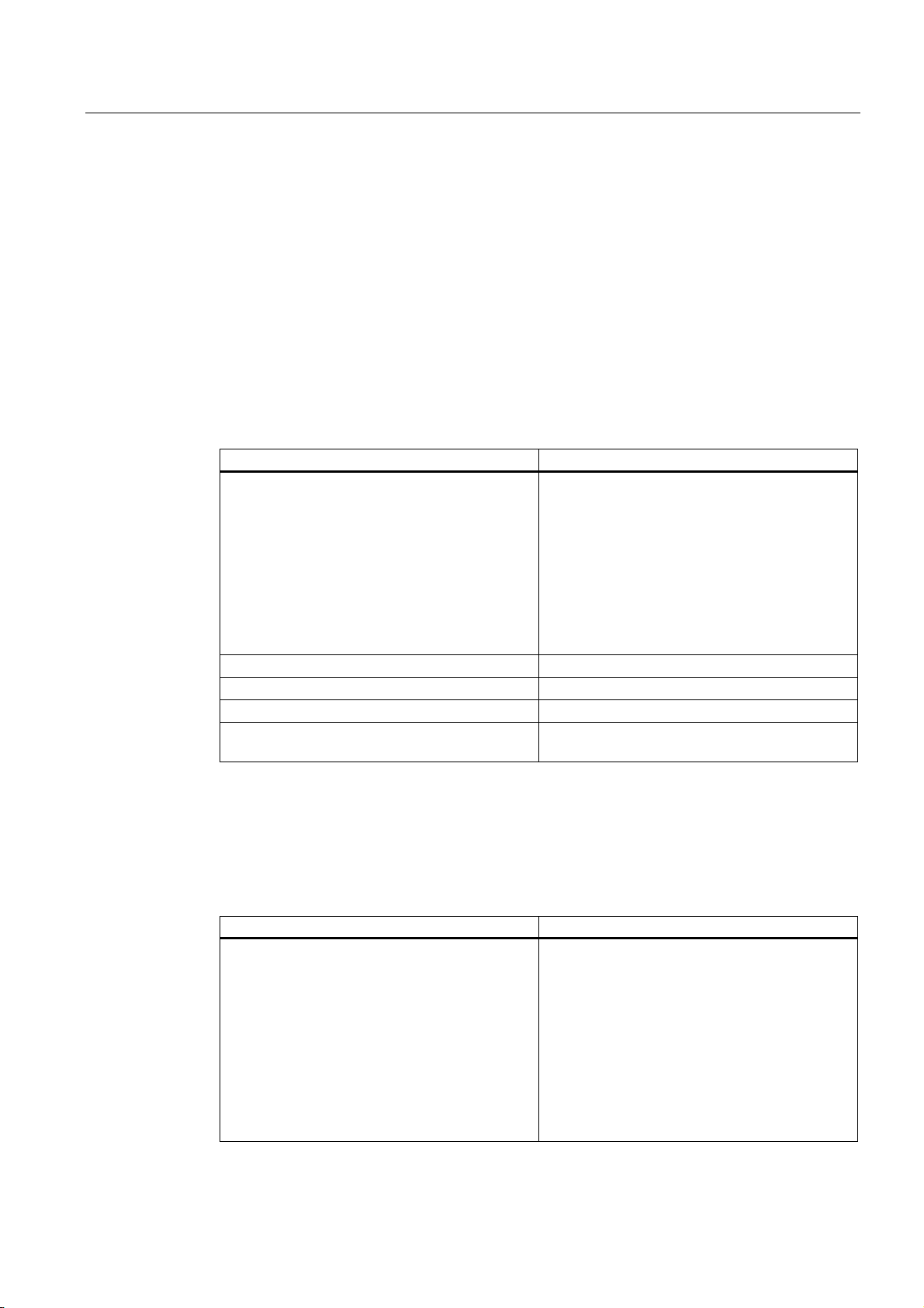
The following table shows the different SIMOTION D versions.
Table 1-1 Product variants
Feature SIMOTION D435 SIMOTION D435 SIMOTION D445
DRIVE CLiQ ports 4 4 6
Axes Up to 4 Up to 16 Up to 64
Fan/battery module Optional Optional Required
Caution
For a SIMOTION D445, a fan/battery module is required for operation.
For a SIMOTION D435 with MLFB 6AU1 435-0AA00-0AA0, a fan/battery module is required
at an ambient temperature of 43°C or higher.
D4xx
Manual, 12.2004, 6AU1900-1AJ32-0BA0
1-3
Introduction
1.4 Product variants
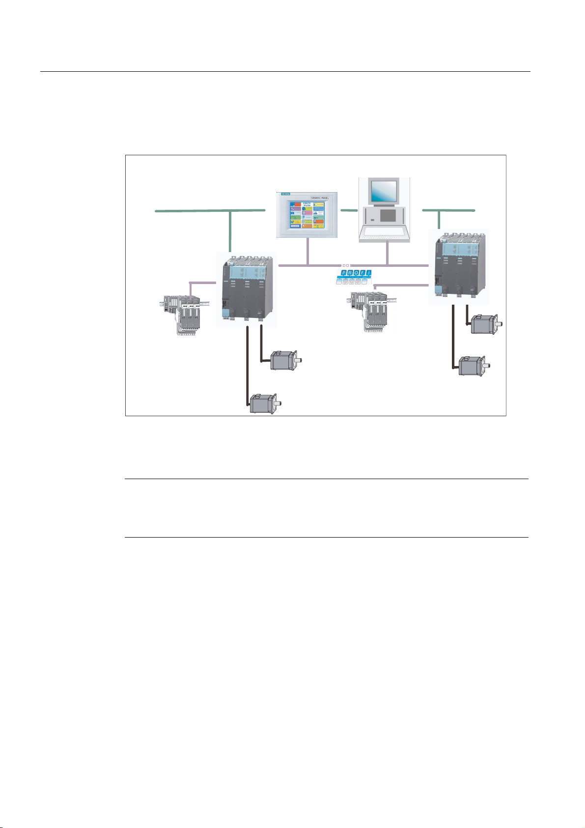
The following figure shows a possible system configuration with a SIMOTION D435.
6,027,216&287
+0,
(WKHUQHW
'LVWULEXWHG,2
'LVWULEXWHG,2
Figure 1-2 System configuration using SIMOTION D with two axes each
(WKHUQHW
Note
In order to cover all variants of SIMOTION D, the product will be referred to as "D4xx".
Specific product designations will be used for information that applies only to one product
version, e.g., D435.
D4xx
1-4 Manual, 12.2004, 6AU1900-1AJ32-0BA0
Introduction
g
1.5 System components
1.5 System components
Introduction
The most important components of the system and their functions are shown below.
Table 1-2 Central components
Component Function
Control unit ... The central unit in the axis assembly
You can use the integrated fast digital I/O as:
• Homing inputs
• Inputs for measuring inputs
• User-addressable process inputs/outputs
The measuring sockets can output any analog
signals.
The DRIVE CLiQ interfaces permit a fast
connection to the SINAMICS drive components.
Line module (SINAMICS S120) ... Generates a DC link from the supply system
Motor module (SINAMICS S120) ... Used to control motors
CX32 ... Enables connection of additional axes
Power supply ... Provides the electronics power supply for
SIMOTION D, e.g., SITOP
System components
The control unit communicates with various components in the automation landscape using
two PROFIBUS-DP and two Ethernet interfaces.
Table 1-3 System components
Component Function
Control unit ... Central motion control module
D4xx
Manual, 12.2004, 6AU1900-1AJ32-0BA0
The control unit communicates via two
PROFIBUS-DP interfaces with the following:
• S7 controllers with PROFIBUS interface
• SIMATIC HMI devices
• Other drives, e.g., SINAMICS S120
• Other control units
• Programming devices (PG/PC)
The control unit can communicate with the
followin
components or be embedded in an
1-5

Introduction
1.5 System components
Component Function
automation landscape by means of Ethernet
interfaces:
• Programming devices (PGs/PCs)
• SIMATIC HMI devices
• Other devices via UDP
Distributed I/O systems
The control unit can communicate via two PROFIBUS-DP interfaces with the following
distributed I/O systems:
Table 1-4 Distributed I/O systems
Distributed I/O Function
SIMATIC ET 200M Modular I/O system for control cabinet installation
and high channel density
SIMATIC ET 200S Highly modular I/O system for control cabinet
installation including motor starters, safety
technology, and individual grouping of the load
groups
SIMATIC ET 200X Modular I/O system with IP 65/67 degree of
protection for machine-related use outside a
control cabinet including motor starters and
pneumatic modules as well as DESINA and
ECOFAST-compliant modules
SIMATIC ET 200eco I/O system with IP 67 degree of protection for
machine-related use without a control cabinet
with flexible and fast ECOFAST or M12
connection methods
Drive units Also as an isochronous slave on PROFIBUS-DP
Other PROFIBUS I/O
ADI4 For the connection of drives with analog ±10 V
setpoint interface
Optional components
The following components enable an expansion of the functionality.
Table 1-5 Optional components for the control unit:
Component Function
Terminal board TB30 ... Enables a terminal expansion (additional
analog and digital I/O)
Terminal module TM31 ... Enables a terminal expansion via DRIVE CLiQ
(additional analog and digital I/O)
Terminal module TM41 ... ... Enables a terminal expansion and encoder
simulation (additional analog and digital I/O) via
DRIVE CLiQ.
Terminal modules TM15 and TM17 High Feature The terminal modules TM15 and TM17 High
D4xx
1-6 Manual, 12.2004, 6AU1900-1AJ32-0BA0

Introduction
1.5 System components
Component Function
Feature are used to implement measuring inputs
and cam outputs. In addition, these terminal
modules provide drive-related digital inputs and
outputs with short signal delay times.
Sensor module cabinets (SMC) ... Enables acquisition of encoder data from
connected motors via DRIVE CLiQ
Operator input and monitoring components
Table 1-6 Additional components that can be connected to the control unit
Component Function
Programming device (PG/PC) ... configures, assigns parameters, programs, and
tests
SIMATIC HMI device ... used for operating and monitoring functions.
This is not an essential requirement for the
operation of a control unit.
Drive units ... convert speed setpoints into signals for
controlling the motor and supply the power
required to operate the motors.
DRIVE CLiQ technology
DRIVE CLiQ (DRIVE Component Link with IQ) is a communication system used to connect
the control unit with the various components of the SINAMICS S120 product family, such as
line modules, motor modules, and encoders.
All components are connected via DRIVE CLiQ.
DRIVE CLiQ offers the following advantages:
• Independent expansion of components possible
• Automatic detection of components by the control unit
• Standardized interfaces to all components
• Uniform diagnostics down to the components
• Complete service down to the components
• Simple mechanical handling
Additional references
You can find detailed information about components in the SINAMICS S120 family of
products in the SINAMICS S120 equipment manual.
D4xx
Manual, 12.2004, 6AU1900-1AJ32-0BA0
1-7

Introduction
1.5 System components
Approved components for SIMOTION D
Note
Modules and devices approved for SIMOTION D are listed in the SIMOTION Motion Control
System, PM 10 Catalog and the "SINAMICS Catalog."
For catalog order numbers, refer to the list of references.
Note
Note that not all modules in the ET 200 I/O family are approved for SIMOTION. Moreover,
system-related functional differences can come into play when these I/O or I/O systems are
used on SIMOTION vs. on SIMATIC. For example, special process-control functions (e.g.
insertion and removal under voltage) are not supported by SIMOTION for the ET 200M
distributed I/O system.
A detailed, regularly updated list of the I/O modules approved for use with SIMOTION, as
well as notes on their use, can be found on the Internet at:
http://www4.ad.siemens.de/view/cs/en/11886029
Besides the I/O modules released for use with SIMOTION, in principle, any certified standard
slave that supports cyclic data exchange (DP V0) and, if required, acyclic data exchange
(DP V1) can be connected to SIMOTION.
These modules are integrated via the GSD file of the device's manufacturer.
Note
Please note that in individual cases further boundary conditions must be fulfilled in order to
integrate a standard slave into SIMOTION. Some modules need "driver modules", e.g. in the
form of function blocks, which make integration possible or much easier.
For modules approved for use with SIMOTION (e.g. S7-300 module FM 350-1, etc.) these
driver blocks are part of the Function Library.
D4xx
1-8 Manual, 12.2004, 6AU1900-1AJ32-0BA0

Description
2.1 Safety notes
Note safety information
Note the following safety information when working with the control unit and its components.
Caution
An option board may only be inserted and removed when the control unit and option board
are disconnected from the power supply.
Notice
The 80 mm clearances above and below the components must be observed. The unit
protects itself from overheating by shutting down.
2
Caution
The Compact Flash card may only be inserted or removed when the control unit is
disconnected from the power supply.
D4xx
Manual, 12.2004, 6AU1900-1AJ32-0BA0
2-1
Description
2.2 D435 and D425
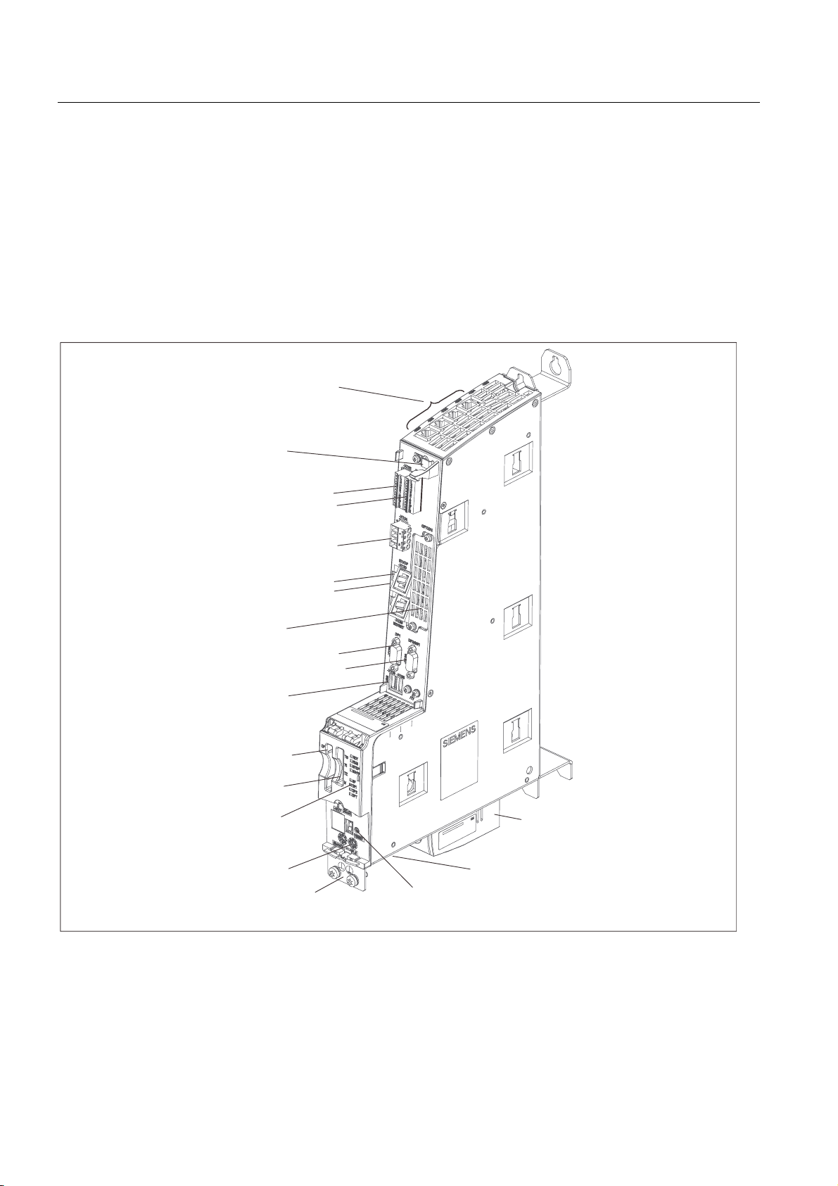
2.2 D435 and D425
Device image
The following figure shows a control unit with its interfaces and front panel components (fault
and status displays).
;;
'5,9(&/L4LQWHUIDFHV
6KLHOGFRQQHFWLRQ
'LJLWDOLQSXWVBRXWSXWV
(OHFWURQLFSRZHUVXSSO\
(WKHUQHWFRQQHFWLRQV
2SWLRQVORW
352),%86'3
352),%86'303, ;
86%[QRIXQFWLRQ
&RPSDFW)ODVKVORW
;
0HDVXULQJVRFNHWV
;;
/('GLVSOD\
0RGHVHOHFWRU
;
;
;
;
;
;
3RWHQWLDOFRQQHFWLRQ
5(6(7EXWWRQ
;
)DQEDWWHU\PRGXOHRSWLRQDO
;ERWWRP56QRIXQFWLRQ
Figure 2-1 Position of interfaces and front panel components
D4xx
2-2 Manual, 12.2004, 6AU1900-1AJ32-0BA0
Description
2.3 D445
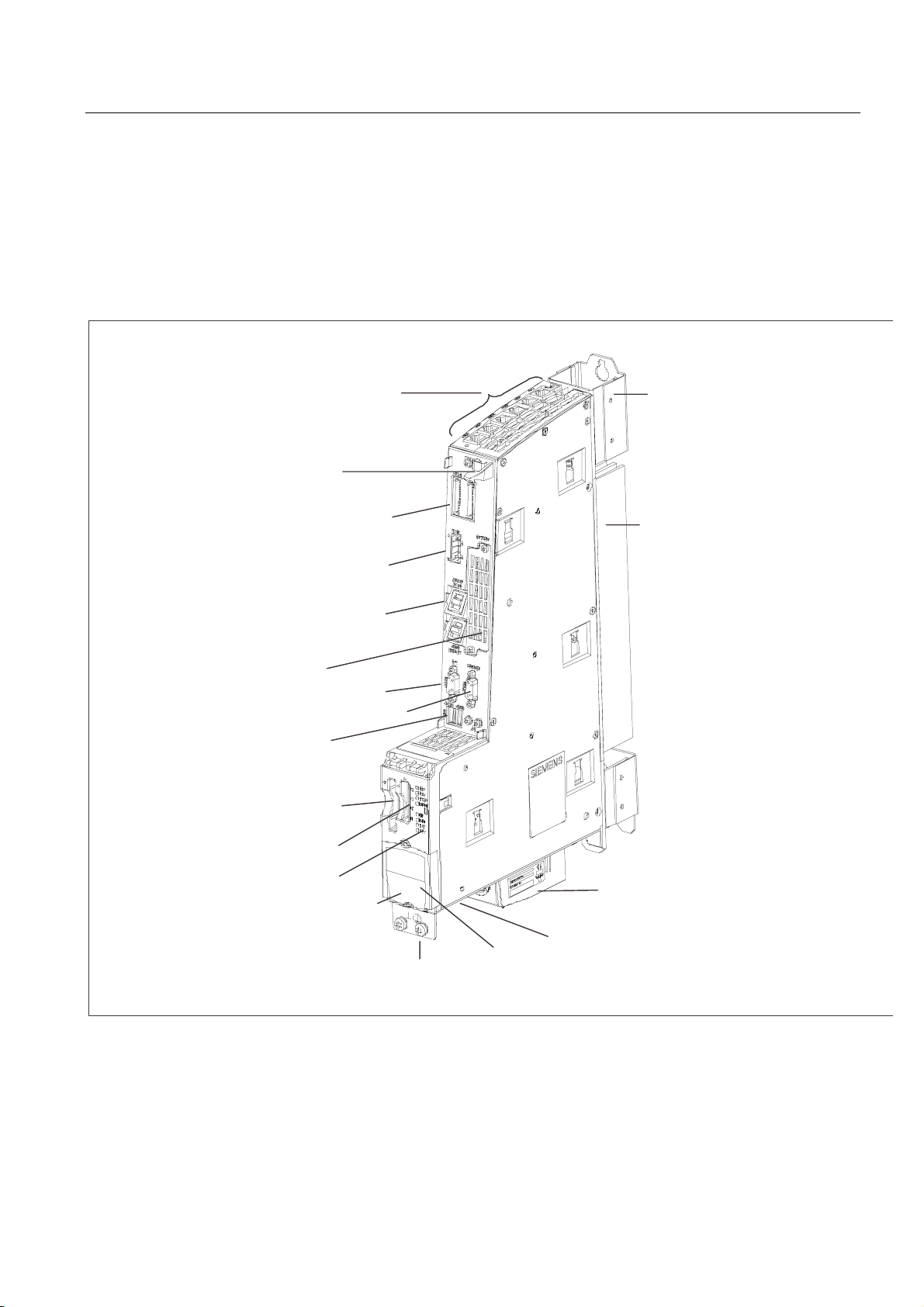
2.3 D445
Device image
The following figure shows the control unit with its interfaces and front panel components
(fault and status displays).
'5,9(&/L4LQWHUIDFHV
;;
6KLHOG&RQQHFWLRQ
'LJLWDOLQSXWVRXWSXWV ;
(OHFWURQLFSRZHUVXSSO\
(WKHUQHWFRQQHFWLRQV
2SWLRQVORW
352),%86'3
352),%86'303,
86%[QRIXQFWLRQ
&RPSDFW)ODVKVORW
;
0HDVXULQJVRFNHWV
;;
/('GLVSOD\
0RGHVHOHFWRU
EHKLQGFRYHU
;
;
;
;
;
;
6SDFHU
&RROLQJULEV
;
)DQEDWWHU\PRGXOH
;ERWWRP56QRIXQFWLRQ
3RWHQWLDOFRQQHFWLRQ
Figure 2-2 Interfaces and display elements
D4xx
Manual, 12.2004, 6AU1900-1AJ32-0BA0
5(6(7EXWWRQEHKLQGFRYHU
2-3
Description
2.4 Clock
Caution
This control unit must be operated with a fan/battery module for heat dissipation. Without a
fan/battery module, the control unit will not start up and cannot be commissioned.
2.4 Clock
Features of real-time clock
The following table contains the features and functions of the control unit clock.
Table 2-1 Clock features
Features Meaning
Type Hardware clock (integrated "realtime clock")
Default setting when delivered DT#1994-01-01-00:00:00
Accuracy
With supply voltage on
0 to 55° C
With supply voltage off
25° C
-20° C to 70° C
Backup time Typically 5 days (at 0 to 25° C)
Charging time 1 hr
Max. deviation per day:
±9 s
±2 s
+2 s to -9 s
With power OFF
In the power OFF state, the control unit clock continues to run during the the backup time
(with the exception of the software clock). The buffer is recharged in the power ON state.
An error message is output if the backup function is defective. With power ON, the clock
resumes at the time set at the factory.
When the control unit is reset to the factory settings, the clock is also reset to the "factory
default setting."
D4xx
2-4 Manual, 12.2004, 6AU1900-1AJ32-0BA0

Description
2.5 Power supply of D425 and D435
2.5 Power supply of D425 and D435
External 24 V power supply
Power is supplied to the control unit by an external 24 V power supply (e.g., SITOP).
Table 2-2 Input voltage specification
Input voltage Typical power
Minimum input voltage 20,4 V 0.7 A 9.8 A
Nominal Input voltage 24 V 0.6 A 8.4 A
Maximum input voltage 28,8 V 0.5 A 7.0 A
Additional references
Recommended power supply units and tables for calculating power consumption for the
assembly with SINAMICS S120 modules can be found in the section on Control-Cabinet
Construction and EMC - Booksize in the SINAMICS S120 Booksize Power Units manual.
Note
A primary-side voltage dip for 20 ms must not cause the voltage on the secondary side
(24 V) to fall below the minimum permissible input voltage to the control unit.
consumption
Maximum power
consumption
D4xx
Manual, 12.2004, 6AU1900-1AJ32-0BA0
2-5
Description
2.6 Power supply of D445
2.6 Power supply of D445
External 24 V power supply
Power is supplied to this control unit by an external 24 V power supply (e.g., SITOP).
Table 2-3 Input voltage specification
Input voltage Typical power
Minimum input voltage 20,4 V 2.35 A 10.6 A
Nominal Input voltage 24 V 2.0 A 9.0 A
Maximum input voltage 28,8 V 1.67 A 7.5 A
Additional references
Recommended power supply units and tables for calculating power consumption for the
assembly with SINAMICS S120 modules can be found in the section on Control-Cabinet
Construction and EMC - Booksize in the SINAMICS S120 Booksize Power Units manual.
Note
A primary-side voltage dip for 20 ms must not cause the voltage on the secondary side
(24 V) to fall below the minimum permissible input voltage to the control unit.
consumption
Maximum power
consumption
D4xx
2-6 Manual, 12.2004, 6AU1900-1AJ32-0BA0
 Loading...