

Siemens SIMOTION D410, SIMOTION D410 DP, SIMOTION D410 DN User Manual

SIMOTION
D410
Manual
Preface
Description
Operation (hardware)
Interfaces
Assembling
Connecting
Technical data
1
2
3
4
5
6
Spare parts/Accessories
Standards and approvals
ESD directives
Appendix
7
A
B
C
Valid for SIMOTION D410 DP and D410 PN
03/2007 Edition

Safety Guidelines
This manual contains notices you have to observe in order to ensure your personal safety, as well as to prevent
damage to property. The notices referring to your personal safety are highlighted in the manual by a safety alert
symbol, notices referring only to property damage have no safety alert symbol. These notices shown below are
graded according to the degree of danger.
Danger
indicates that death or severe personal injury will result if proper precautions are not taken.
Warning
indicates that death or severe personal injury may result if proper precautions are not taken.
Caution
with a safety alert symbol, indicates that minor personal injury can result if proper precautions are not taken.
Caution
without a safety alert symbol, indicates that property damage can result if proper precautions are not taken.
Notice
indicates that an unintended result or situation can occur if the corresponding information is not taken into
account.
If more than one degree of danger is present, the warning notice representing the highest degree of danger will
be used. A notice warning of injury to persons with a safety alert symbol may also include a warning relating to
property damage.
Qualified Personnel
The device/system may only be set up and used in conjunction with this documentation. Commissioning and
operation of a device/system may only be performed by qualified personnel. Within the context of the safety notes
in this documentation qualified persons are defined as persons who are authorized to commission, ground and
label devices, systems and circuits in accordance with established safety practices and standards.
Prescribed Usage
Note the following:
Warning
This device may only be used for the applications described in the catalog or the technical description and only in
connection with devices or components from other manufacturers which have been approved or recommended by
Siemens. Correct, reliable operation of the product requires proper transport, storage, positioning and assembly
as well as careful operation and maintenance.
Trademarks
All names identified by ® are registered trademarks of the Siemens AG. The remaining trademarks in this
publication may be trademarks whose use by third parties for their own purposes could violate the rights of the
owner.
Disclaimer of Liability
We have reviewed the contents of this publication to ensure consistency with the hardware and software
described. Since variance cannot be precluded entirely, we cannot guarantee full consistency. However, the
information in this publication is reviewed regularly and any necessary corrections are included in subsequent
editions.
Siemens AG
Automation and Drives
Postfach 48 48
90437 NÜRNBERG
GERMANY
Order No.:
Ⓟ 03/2007
Copyright © Siemens AG 2007.
Technical data subject to change

Preface
Equipment Manual contents
This document is part of the SIMOTION D4xx Programming documentation package,
Version 03/2007.
The Manual describes the SIMOTION devices D410 DP and D410 PN.
Information in this Manual
The following is a description of the purpose and use of the equipment Manual:
• Description
This chapter provides information on the SIMOTION System and how it integrates into
the information landscape.
• Operator Control (hardware)
This chapter describes the operating elements and how to operate them.
• Dimensional diagrams
This chapter contains the SIMOTION D410 dimensional diagrams.
• Interfaces
This section provides information on the interfaces, pin assignments and application
options.
• Installation
This section explains how you configure a mechanical layout and install the
SIMOTION D410 in a control cabinet.
• Connecting
This chapter describes how to connect and network the SIMOTION D410.
• Technical data
This chapter describes the properties and features of the SIMOTION D410.
• Spare Parts/Accessories
This chapter provides information on accessories and spare parts for the
SIMOTION D410.
• Appendix
D410
Manual, 03/2007 Edition
This section provides information on the various standards and specifications that the
device complies with.
• Index to locate information
3

Preface
SIMOTION Documentation
An overview of the SIMOTION documentation can be found in a separate list of references.
This documentation is included as electronic documentation with the supplied
SIMOTION SCOUT.
The SIMOTION documentation consists of 9 documentation packages containing
approximately 60 SIMOTION documents and documents on other products (e.g.
SINAMICS).
The following documentation packages are available for SIMOTION V4.1:
• SIMOTION Engineering System
• SIMOTION System and Function Descriptions
• SIMOTION Diagnostics
• SIMOTION Programming
• SIMOTION Programming - References
• SIMOTION C2xx
• SIMOTION P350
• SIMOTION D4xx
• SIMOTION Supplementary Documentation
Hotline and Internet addresses
If you have any technical questions, please contact our hotline (worldwide):
A&D Technical Support:
• Phone: +49 (180) 50 50 222
• Fax: +49 (180) 50 50 223
• E–mail: adsupport@siemens.com
• Internet: http://www.siemens.de/automation/support-request
If you have any questions, suggestions, or corrections regarding the documentation, please
fax or e-mail them to:
• Fax: +49 (9131) 98 63315
• E–mail: docu.motioncontrol@siemens.com
Siemens Internet address
The latest information about SIMOTION products, product support, and FAQs can be found
on the Internet at:
• General information:
– http://www.siemens.de/simotion (German)
– http://www.siemens.com/simotion (international)
• Product support:
– http://support.automation.siemens.com/WW/view/en/10805436
D410
4 Manual, 03/2007 Edition

Preface
Additional support
We also offer introductory courses to help you familiarize yourself with SIMOTION.
Please contact your regional training center or our main training center at D-90027
Nuremberg, phone +49 (911) 895 3202.
Disposal and recycling
SIMOTION D410 is an environmentally friendly product! It includes the following features:
• In spite of its excellent resistance to fire, the flame-resistant agent in the plastic used for
the housing does not contain halogens.
• Identification of plastic materials in accordance with DIN 54840
• Less material used because the unit is smaller and with fewer components thanks to
integration in ASICs
SIMOTION D410 can be recycled because it is made with low-polluting materials.
For state-of-the art environmentally friendly recycling and disposal of your old modules,
contact your Siemens representative. To locate your representative, visit us online at:
http://www.ad.siemens.com/partner
D410
Manual, 03/2007 Edition
5


Table of contents
Preface ...................................................................................................................................................... 3
1 Description............................................................................................................................................... 11
1.1 System overview ..........................................................................................................................11
1.2 System components ....................................................................................................................13
1.3 SIMOTION D410 DP display .......................................................................................................17
1.4 SIMOTION D410 PN display .......................................................................................................20
1.5 Safety information ........................................................................................................................22
2 Operation (hardware)............................................................................................................................... 23
2.1 Overview of operator controls and indicators ..............................................................................23
2.2 Operator controls .........................................................................................................................24
2.2.1 Mode selector switch ...................................................................................................................24
2.2.2 SIMOTION CompactFlash card...................................................................................................25
2.3 Error and status indicators ...........................................................................................................26
3 Interfaces................................................................................................................................................. 27
3.1 Overview of interfaces .................................................................................................................27
3.2 Digital inputs/outputs....................................................................................................................28
3.3 DRIVE-CLiQ interface..................................................................................................................32
3.4 PROFIBUS DP interface (SIMOTION D410 DP only) .................................................................35
3.5 PROFINET interface (SIMOTION D410 PN only) .......................................................................37
3.6 HTL/TTL encoder interface ..........................................................................................................38
3.7 EP terminals/temperature sensor connection..............................................................................39
3.8 Power supply................................................................................................................................40
3.9 Measuring sockets .......................................................................................................................42
3.10 Power Module Interface ...............................................................................................................42
4 Assembling.............................................................................................................................................. 43
4.1 General requirements ..................................................................................................................43
4.2 SIMOTION D410 mounted on the power module..................
......................................................43
4.3 Mounting SIMOTION D410 on the mounting plate......................................................................46
5 Connecting .............................................................................................................................................. 47
5.1 Overview ......................................................................................................................................47
5.2 General rules for operating the SIMOTION D410........................................................................48
5.3 Overview of SIMOTION D410 connections .................................................................................50
D410
Manual, 03/2007 Edition
7

Table of contents
5.4 Connecting the protective ground ............................................................................................... 50
5.5 Connecting the power supply...................................................................................................... 51
5.6 Connecting DRIVE-CLiQ components........................................................................................ 52
5.7 Connecting the digital inputs/outputs .......................................................................................... 53
5.8 Connecting the PROFINET interface (410 PN only)................................................................... 54
5.9 Connecting the PROFIBUS DP interface (410 DP only) ............................................................ 55
5.9.1 Connection components in PROFIBUS...................................................................................... 55
5.9.2 PROFIBUS cables and connectors............................................................................................. 55
5.9.3 PROFIBUS cable lengths............................................................................................................ 56
5.9.4 Rules for routing PROFIBUS cables........................................................................................... 56
5.9.5 Connecting PROFIBUS DP (interface X21)................................................................................ 57
5.9.6 Connection rules in the PROFIBUS subnet................................................................................ 58
5.10 Connecting an external encoder ................................................................................................. 60
6 Technical data ......................................................................................................................................... 61
6.1 SIMOTION D410 dimensional diagram ...................................................................................... 61
6.2 System data, connection values, dimensions and weight .......................................................... 62
6.3 Digital inputs/outputs................................................................................................................... 63
6.4 Shipping and storage conditions................................................................................................. 64
6.5 Mechanical and climatic ambient conditions............................................................................... 64
6.6 Specifications for dielectric tests, safety class and degree of protection.................................... 66
7 Spare parts/Accessories.......................................................................................................................... 67
7.1 Terminal module TM31 ............................................................................................................... 67
7.2 Terminal module TM41 ............................................................................................................... 68
7.3 Terminal modules TM15 and TM17 High Feature ...................................................................... 69
7.4 CUA31 control unit adapter......................................................................................................... 70
7.5 DMC20 DRIVE-CLiQ hub............................................................................................................ 71
7.6 List of spare parts and accessories ............................................................................................ 72
A Standards and approvals......................................
................................................................................... 73
A.1 General rules............................................................................................................................... 73
A.2 Safety of electronic controllers.................................................................................................... 74
A.3 Electromagnetic Compatibility..................................................................................................... 75
B ESD directives......................................................................................................................................... 77
B.1 ESD definition ............................................................................................................................. 77
B.2 Electrostatic charging of individuals............................................................................................ 78
B.3 Basic measures for protection against discharge of static electricity ......................................... 78
C Appendix.................................................................................................................................................. 79
C.1 References.................................................................................................................................. 79
C.2 List of abbreviations .................................................................................................................... 81
D410
8 Manual, 03/2007 Edition

Table of contents
Index........................................................................................................................................................ 83
Tables
Table 1-1
System components ....................................................................................................................13
Table 1-2 Components on PROFIBUS DP ..................................................................................................14
Table 1-3 Components on PROFINET ........................................................................................................15
Table 1-4 Components on DRIVE-CLiQ ......................................................................................................16
Table 1-5 SIMOTION D410 interfaces.........................................................................................................18
Table 1-6 SIMOTION D410 interfaces.........................................................................................................21
Table 2-1 Mode selector switch settings......................................................................................................24
Table 3-1 Overview of available SIMOTION D410 interfaces......................................................................27
Table 3-2 Overview of non-usable SIMOTION D410 interfaces..................................................................27
Table 3-3 Interface X121..............................................................................................................................28
Table 3-4 Interface assignment X121 ..........................................................................................................29
Table 3-5 Interface X100..............................................................................................................................32
Table 3-6 Interface assignment X100 ..........................................................................................................32
Table 3-7 DRIVE-CLiQ connection topology................................................................................................33
Table 3-8 Interface X21................................................................................................................................35
Table 3-9 Interface assignment X21 ............................................................................................................35
Table 3-10 Ports X200 and X201...................................................................................................................37
Table 3-11 Assignment of ports X200 - X201 ................................................................................................37
Table 3-12 Interface X23................................................................................................................................38
Table 3-13 Interface assignment X23 ............................................................................................................38
Table 3-14 Interface X120..............................................................................................................................39
Table 3-15 Interface assignment X120 ..........................................................................................................39
Table 3-16 Interface X124..............................................................................................................................41
Table 3-17 Interface assignments T0, T1 and T2 ..........................................................................................42
Table 5-1 System startup .............................................................................................................................48
Table 5-2 Supply voltage .............................................................................................................................48
Table 5-3 24 V DC supply voltage ...............................................................................................................48
Table 5-4 Protection against external electrical interference .......................................................................49
Table 5-5 Electrical parameters of the required load power supply.............................................................51
Table 5-6 Features of PROFIBUS cables....................................................................................................55
Table 5-7 Permitted cable length of a subnet segment for specific baud rates ...........................................56
Table 5-8 Boundary conditions for routing of PROFIBUS cables ................................................................57
Table 6-1 Memory for system data and its memory size .............................................................................62
D410
Manual, 03/2007 Edition
9

Table of contents
Table 6-2 SIMOTION D410 electrical connection values............................................................................ 62
Table 6-3 SIMOTION D410 dimensions and weight ................................................................................... 62
Table 6-4 CF card........................................................................................................................................ 62
Table 6-5 Digital input technical data .......................................................................................................... 63
Table 6-6 Digital output technical data........................................................................................................ 63
Table 6-7 Shipping and storage conditions................................................................................................. 64
Table 6-8 Mechanical ambient conditions................................................................................................... 65
Table 6-9 Climatic ambient conditions ........................................................................................................ 65
Table 6-10 Test voltages............................................................................................................................... 66
Table 7-1 Interface overview of the TM31................................................................................................... 67
Table 7-2 TM41 interface overview ............................................................................................................. 68
Table 7-3 Overview of CUA31 interfaces.................................................................................................... 70
Table 7-4 Spare parts and accessories ...................................................................................................... 72
Table A-1 EMC Directive ............................................................................................................................. 73
Table A-2 EMC standards ........................................................................................................................... 75
Table C-1 Abbreviations .............................................................................................................................. 81
D410
10 Manual, 03/2007 Edition

Description
1.1 System overview
Overview
In SIMOTION D, the SIMOTION functionality is integrated directly in the closed-loop control
module of the SINAMICS S120 drive system.
SIMOTION D410 is a module drive system for single axes, which solves demanding drive
tasks for a very wide range of industrial applications. SIMOTION D410 supplements D425,
D435 and D445, the three power levels for multi-axis connections.
SIMOTION D is an integral part of the Totally Integrated Automation (TIA) concept. TIA
features standardized data management, configuration and communication over all products
and systems. Thus, an extensive toolbox of automation modules is also available for
SIMOTION D410.
Application
Combining a power module with SIMOTION D410 forms a compact single drive for machine
and plant engineering.
1
Product variants
D410
Manual, 03/2007 Edition
Applications include:
• Machine concepts with central drive (e.g., pressing, printing, packaging)
• Modular machine concepts where the machine modules broken down to single axes
• Single drives with high accuracy, stability and concentricity requirements (compared with
standard drives) in machine and industrial plant engineering
• Single drives for transport tasks (conveying, raising, lowering)
• Single drives with integrated PLC functionality and expanded motion control functionality
such as output cam or cams
• Drives without power recovery (wire drawing, extruding)
• Drive connections with high availability requirements (incoming supply failure may not
cause all axes to fail)
SIMOTION D410 comes in two variants:
• SIMOTION D410 DP with PROFIBUS DP interface.
• SIMOTION D410 PN with PROFINET interface.
11
Description
1.1 System overview
System integration
SIMOTION provides an optimized system platform for automation and drive solutions where
the main focus is on motion control applications and technology tasks.
The SIMOTION system is made up of three components:
• SIMOTION SCOUT Engineering System
• Runtime Software
• Hardware platforms
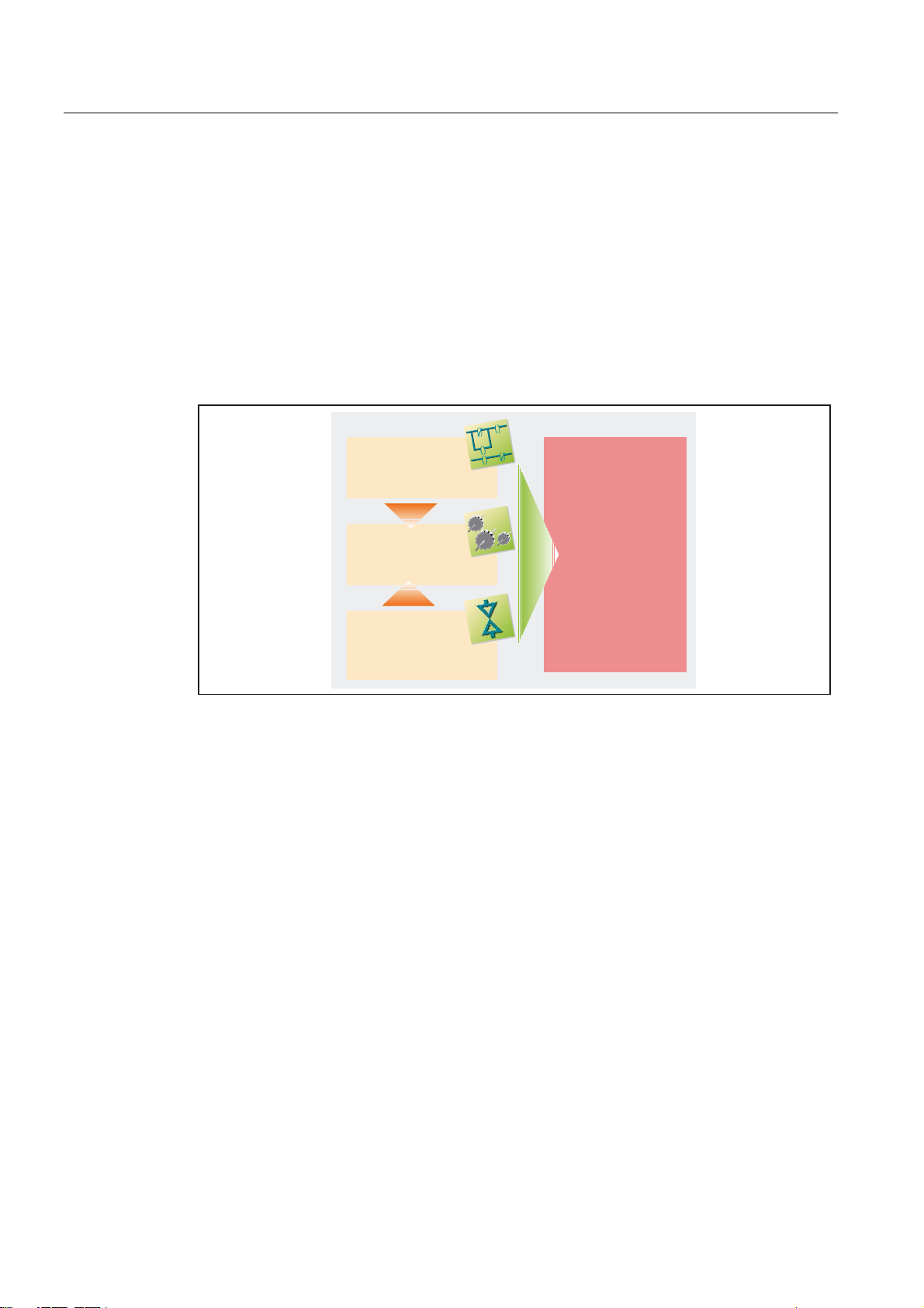
The innovative SIMOTION concept involves integrating pure automation and motion
functions, which have been traditionally isolated in the past.
3/&IXQFWLRQDOLW\
,(&
7KHV\VWHPDSSURDFKRI
0RWLRQ&RQWURO
HJSRVLWLRQLQJ
V\QFKURQRXV
RSHUDWLRQHWF
7HFKQRORJ\
IXQFWLRQV
HJK\GUDXOLFV
WHPSHUDWXUHFRQWUROHWF
Figure 1-1 System solution
6,027,21
7KHIXVLRQRI0RWLRQ
&RQWURO3/&DQG
WHFKQRORJ\IXQFWLRQV
SIMOTION can be used with all machines with motion control tasks. The focus is on a
simple and flexible solution to a wide variety of motion control tasks. In order to achieve this
in the best way possible, a new system approach has been introduced:
the fusion of motion control with two other control functions, which are found in most
machines: PLC and technology functions.
This approach enables motion control of axes and machines with only one system. The
same applies to technology functions, such as pressure control of a hydraulic axis. A
seamless switch can be made from position-controlled positioning mode to pressure control.
The fusion the three control functions motion control, PLC and technology has the following
advantages:
• Lower engineering expenditure and higher machine performance.
• Interfaces between individual components requiring rapid response are no longer
needed.
• Simple, standardized and transparent programming and diagnostics for the complete
machine.
D410
12 Manual, 03/2007 Edition

Description
1.2 System components
1.2 System components
Overview
SIMOTION D410 communicates with the components of the automation landscape via the
following interfaces:
• PROFIBUS DP (SIMOTION D410 DP only)
• PROFINET (SIMOTION D410 PN only)
• DRIVE-CLiQ (DRIVE Component Link with IQ)
• Power Module Interface (PM-IF)
The most important system components and their functions are listed in the following table.
Table 1-1 System components
Components Function
SIMOTION D410 ... is the central motion control module.
The module contains the programmable SIMOTION Runtime in
SIMOTION D410 and the SINAMICS S120 drive software.
You can use the integrated rapid digital I/Os as:
• Homing inputs
• Inputs for measuring inputs
• User-addressable process inputs/outputs
• Outputs for fast output cams
The measuring sockets can output any analog signals.
The DRIVE-CLiQ interfaces permit a fast connection to the SINAMICS drive
components.
System software The system software is delivered separately on a CompactFlash card (not
included in the scope of delivery).
Note: An additional license is not required for the real axis technology.
Power supply (PS) ... provides the electronic power supply for SIMOTION D410, e.g., SITOP.
Note: If SIMOTION D410 is to be mounted on the power module, the power is
supplied via the power module (e.g., PM340). The digital outputs of
SIMOTION D410 are not supplied by the power supply.
D410
Manual, 03/2007 Edition
13

Description
1.2 System components
PROFIBUS DP
SIMOTION D410 DP can communicate via PROFIBUS DP interface to the following
components:
Table 1-2 Components on PROFIBUS DP
Components Function
PG/PC programming device ... configures, sets parameters, programs and tests using the
SIMOTION SCOUT Engineering System (ES).
Drive units with
PROFIBUS DP interface
(e.g., SINAMICS,
SIMODRIVE 611 universal)
SIMATIC ET 200M Modular I/O system for control cabinet installation and high channel
SIMATIC ET 200S Precision modular I/O system for control cabinet installation, including
SIMATIC ET 200pro Modular I/O system with IP65/66/67 rating for near-machine
SIMATIC ET 200eco I/O system with IP 67 rating for near-machine applications with no
Gateways
Teleservice adapter Remote diagnosis
Other controls (e.g.,
SIMOTION or SIMATIC)
... convert speed setpoints into signals for controlling the motor and
supply the power required to operate the motors.
Can also be operated as an isochronous, equidistant Slave on the
PROFIBUS DP.
densities.
motor starters, safety technology and connecting load groups to
common potential.
applications with no control cabinet; with new features like more
compact designs, integrated PROFIsafe safety technology,
PROFINET connection and live module replacement.
control cabinet, including flexible and fast connection system in
ECOFAST or M12.
• DP/AS Interface Link 20E and DP/AS Interface Link Advanced for
the PROFIBUS DP gateway to AS Interface
• DP/DP coupler to connect two PROFIBUS DP networks
Note
Note that only a real axis can be used on a SIMOTION D410!
D410
14 Manual, 03/2007 Edition
Note
Please note that not all modules for the I/O systems listed above are enabled for SIMOTION.
Moreover, system-related functional differences can come into play when these I/O or I/O
systems are used on SIMOTION vs. on SIMATIC. For example, SIMOTION does not support
special process control functions (e.g., live plugging and unplugging, etc.) in the ET 200M
distributed I/O system.
For a detailed and routinely updated list of I/O modules enabled with SIMOTION as well as
application information, visit us online at:
http://support.automation.siemens.com/WW/view/de/11886029

Description
1.2 System components
In addition to the I/O modules enabled for SIMOTION, all certified standard slaves can, in
principle, be connected to SIMOTION if they support the following:
• Cyclic data traffic (DP-V0) and, possibly
• Acyclic data traffic (DP-V1) or
• Isochronous data traffic (DP-V2)
These modules are integrated via the GSD file from the device manufacturer.
PROFINET
Note
Please note that in individual cases further boundary conditions must be fulfilled in order to
integrate a standard slave into SIMOTION. For example, "driver modules" in the form of
function blocks are required for some modules, which enable integration or make it
especially easy.
For modules enabled for SIMOTION (e.g., S7-300 module FM 350-1, etc.), these driver
modules are part of the SIMOTION SCOUT Engineering System command library.
SIMOTION D410 PN can communicate via PROFINET interface to the following
components:
Table 1-3 Components on PROFINET
Components Function
PG/PC programming device ... communicates with the SIMOTION SCOUT Engineering
Systems (ES), STEP 7 and HMI (Human Machine Interface).
Host computer ... communicates to other devices via TCP/IP.
SIMATIC HMI device ... is used for operator control and monitoring functions. It is not
absolutely required to run SIMOTION D410.
SIMATIC ET 200S Precision modular I/O system for control cabinet installation,
including motor starters, safety technology and connecting load
groups to common potential.
SIMATIC ET 200pro Modular I/O system with IP65/66/67 rating for near-machine
applications with no control cabinet; with new features like more
compact designs, integrated PROFIsafe safety technology,
PROFINET connection and live module replacement.
Drive units with PROFINET
interface (e.g., SINAMICS S120
with CBE20)
Other controls (e.g., SIMOTION
or SIMATIC)
Gateways
... convert speed setpoints into signals for controlling the motor
and supply the power required to operate the motors.
• IE/AS Interface Link PN IO for the PROFINET IO gateway to
AS Interface
• PN/PN coupler to connect two PROFINET IO networks
• IE/PB Link PN IO for the PROFINET IO gateway to PROFIBUS
DP
D410
Manual, 03/2007 Edition
15

Description
1.2 System components
DRIVE-CLiQ
SIMOTION D410 can communicate via DRIVE-CLiQ interface to the following components:
Table 1-4 Components on DRIVE-CLiQ
Components Function
Drive units
SINAMICS S120 AC DRIVE
(with CUA31)
TM15 and TM17 High Feature
terminal modules
TM31 terminal module ... enables terminal expansion via DRIVE-CLiQ (additional
TM41 terminal module ... enables terminal expansion (analog and digital inputs/outputs)
Sensor Module Integrated (SMI) The integrated sensor module delivers the encoder signals
Sensor Module Cabinets (SMC) ... converts the encoder signals into DRIVE-CLiQ signals.
DMC20 ... expands the number of DRIVE-CLiQ nodes
... convert speed setpoints into signals for controlling the motor
and supply the power required to operate the motors. The
AC DRIVE component PM340 is connected via CUA31. No more
than one PM340 can be connected. Chassis power module is
connected via DRIVE-CLiQ.
Note: Booksize components are not supported!
The TM15 and TM17 High Feature terminal modules can be
used to set up inputs of measuring inputs and outputs of output
cams. In addition, these terminal modules provide drive-related
digital inputs and outputs with short signal delay times.
analog and digital inputs/outputs).
and encoder simulation via DRIVE-CLiQ.
directly as DRIVE-CLiQ signals.
Note
Note that SIMOTION D410 does not support the CX32 expansion!
D410
16 Manual, 03/2007 Edition

Description
1.3 SIMOTION D410 DP display
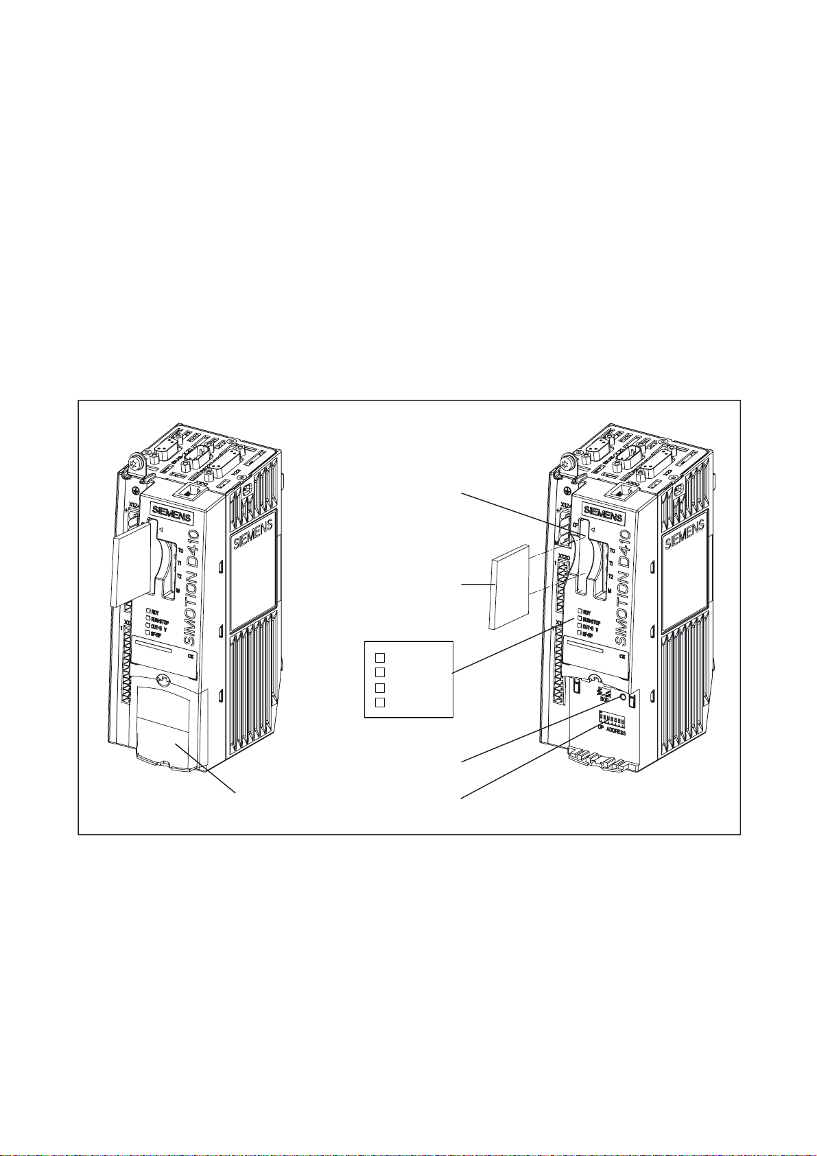
1.3 SIMOTION D410 DP display
View
The following figure shows SIMOTION D410 DP with the interfaces and front elements.
3RZHUPRGXOHLQWHUIDFH30,)
6HULDOLQWHUIDFHQR
IXQFWLRQ
;
352),%86
0VFUHZRQVKLHOG
FRQQHFWLRQ
;
(QFRGHULQWHUIDFH+7/77/
;
'5,9(&/L4LQWHUIDFH
;
(OHFWURQLFVSRZHUVXSSO\
&RPSDFW)ODVKb&DUG
;
(3WHUPLQDOVWHPSHUDWXUH
VHQVRUFRQQHFWLRQ
;
'LJLWDOLQSXWVRXWSXWV
Figure 1-2 Location of interfaces and front elements in SIMOTION D410 DP
6LGHQDPHSODWH
7770
0HDVXULQJVRFNHWV
/('GLVSOD\V
1DPHSODWH
5(6(7EXWWRQ
0RGHVHOHFWRUVZLWFK
',/VZLWFK
D410
Manual, 03/2007 Edition
Note
The lettering "DP ADDRESS" below the DIL switch is of no interest.
17
Description
1.3 SIMOTION D410 DP display
Interfaces
The SIMOTION D410 DP interfaces are described in the following tables.
Table 1-5 SIMOTION D410 interfaces
Interface Description
Digital inputs/outputs
X121
DRIVE-CLiQ interface
X100
PROFIBUS DP interface
X21
Power Module Interface
(PM-IF)
Encoder interface (HTL/TTL)
X23
EP terminals/temperature
sensor connection
X120
Power supply connection
X124
Measuring sockets
T0, T1, T2 and M
• 4 digital inputs: Socket to connect switches or proximity sensors
• 4 digital inputs/outputs: 12-pin socket to connect actuators and
sensors
8-pin RJ45plus socket to connect DRIVE-CLiQ nodes
9-pin SUB-D socket to connect to PROFIBUS DP
8-pin direct connector to connect to a blocksize power module
15-pin SUB-D socket to connect HTL and TTL encoders.
8-pin Mini Combicon to connect input terminals ("safe standstill") or
to connect temperature sensing via KTY or PTC
4-pin screw terminal connection to connect the 24 V DC load power
supply
Sockets to output analog signals
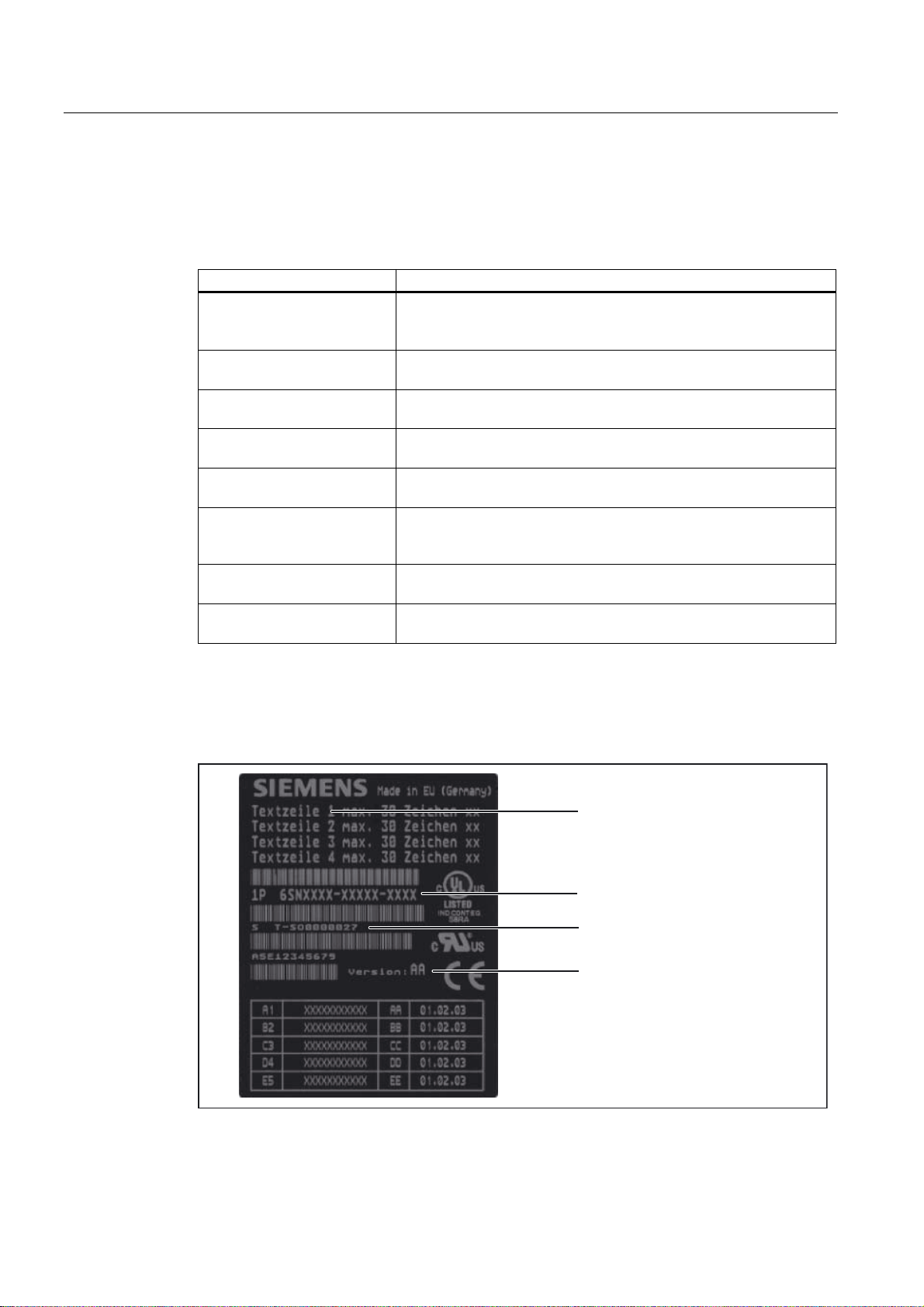
Nameplates
The following figure shows you all the information included on the nameplates located on the
side of the unit.
0RGXOHGHVLJQDWLRQ
2UGHUQXPEHU
6HULDOQXPEHU
+:YHUVLRQ
Figure 1-3 SIMOTION D410 nameplate
D410
18 Manual, 03/2007 Edition

Description
$8$$$$
81,.$761U
6DFK1U$(
9HUVLRQ
$$
1.3 SIMOTION D410 DP display
The following nameplate includes the SIMOTION D410 DP barcode numbers and is located
on the front side of the module.
%DUFRGH0/)%1R$8$$$$
%DUFRGH8QLTXH1R
%DUFRGH3URGXFW1R$(
3URGXFWQXPEHU
8QLTXHQXPEHU
2UGHUQXPEHU0/)%1R
$UHDIRU&(8/LGHQWLILFDWLRQ
3URGXFWYHUVLRQ
Figure 1-4 SIMOTION D410 DP nameplate (example)
Note
The contents of the individual nameplate fields on the current module may differ from those
described in this Manual (e.g., updated product status, approvals and identifications not yet
issued, etc.).
D410
Manual, 03/2007 Edition
19

Description
1.4 SIMOTION D410 PN display
1.4 SIMOTION D410 PN display
View
The following figure shows SIMOTION D410 PN with the interfaces and front elements.
3RZHUPRGXOHLQWHUIDFH30,)
6HULDOLQWHUIDFHQR
IXQFWLRQ
;;
352),1(7VRFNHWV
0VFUHZRQVKLHOG
FRQQHFWLRQ
;
(QFRGHULQWHUIDFH+7/77/
;
'5,9(&/L4LQWHUIDFH
;
(OHFWURQLFVSRZHUVXSSO\
&RPSDFW)ODVKb&DUG
;
(3WHUPLQDOVWHPSHUDWXUH
VHQVRUFRQQHFWLRQ
;
'LJLWDOLQSXWVRXWSXWV
Figure 1-5 Location of interfaces and front elements in SIMOTION D410 PN
6LGHQDPHSODWH
7770
0HDVXULQJVRFNHWV
/('GLVSOD\V
1DPHSODWH
5(6(7EXWWRQ
0RGHVHOHFWRUVZLWFK
',/VZLWFK
Note
The lettering "DP ADDRESS" below the DIL switch is of no interest.
D410
20 Manual, 03/2007 Edition

Description
1.4 SIMOTION D410 PN display
Interfaces
The SIMOTION D410 PN interfaces are described in the following tables.
Table 1-6 SIMOTION D410 interfaces
Interface Description
Digital inputs/outputs
X121
DRIVE-CLiQ interface
X100
PROFINET interface
(ports X200 and X201)
Power Module Interface
(PM-IF)
Encoder interface (HTL/TTL)
X23
EP terminals/temperature
sensor connection
X120
Power supply connection
X124
Measuring sockets
T0, T1, T2 and M
• 4 digital inputs: Socket to connect switches and proximity
sensors
• 4 digital inputs/outputs: 12-pin socket to connect actuators and
sensors
8-pin RJ45plus socket to connect DRIVE-CLiQ nodes
8-pin RJ45plus socket to connect to PROFINET
8-pin direct connector to connect to a blocksize power module
15-pin SUB-D socket to connect HTL and TTL encoders.
8-pin Mini Combicon to connect input terminals ("safe standstill")
or to connect temperature sensing via KTY or PTC
4-pin screw terminal connection to connect the 24 V DC load
power supply
Sockets to output analog signals
Nameplates
The following figure shows you all the information included on the nameplates located on the
side of the unit.
0RGXOHGHVLJQDWLRQ
2UGHUQXPEHU
6HULDOQXPEHU
+:YHUVLRQ
Figure 1-6 SIMOTION D410 nameplate
D410
Manual, 03/2007 Edition
21
Description
9HUVLRQ
$(
;;;;;;
$8$%$$
1.5 Safety information
The following nameplate includes the MAC address of the PROFINET interface (ports X200
and X201) and is located on the front side of the module.
%DUFRGH0$&$GGUHVV
0$&DGGUHVV
3URGXFWQXPEHU
2UGHUQXPEHU0/)%1R
Figure 1-7 SIMOTION PN nameplate (example)
Note
The contents of the individual nameplate fields on the current module may differ from those
described in this Manual (e.g., updated product status, approvals and identifications not yet
issued, etc.).
1.5 Safety information
Observe the following safety information when working with SIMOTION D410 and its
components!
$UHDIRU&(8/LGHQWLILFDWLRQ
3URGXFWYHUVLRQ
Caution
The CompactFlash card may only be unplugged and plugged in when SIMOTION D410 is
switched off (zero current)!
Caution
The 50 mm clearances above and below the components must be observed. The ventilation
openings may not be covered by connecting cables.
D410
22 Manual, 03/2007 Edition
Operation (hardware)
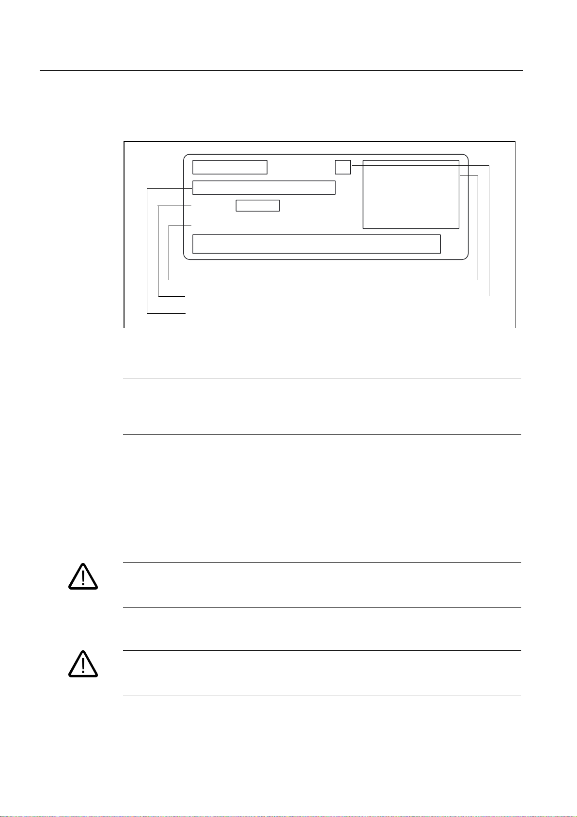
2.1 Overview of operator controls and indicators
The following figure shows the operator controls and indicators arrangement on the
SIMOTION D410.
&RPSDFW)ODVKFDUG
VORW
&RPSDFW)ODVKb&DUG
/('GLVSOD\V
2
%ODQNLQJSODWH
Figure 2-1 Operator controls and indicators
The operator controls and indicators are described below.
5'<
5816723
287!9
6)%)
5(6(7EXWWRQ
',/VZLWFKHV
D410
Manual, 03/2007 Edition
23
Operation (hardware)
2.2 Operator controls
2.2 Operator controls
2.2.1 Mode selector switch
DIL switches
The mode selector switch function is realized in SIMOTION D410 by a DIL switch
(DIL = Dual In Line Package). The DIL switch is located in the lower front area of the
SIMOTION D410 (see "Overview of operator controls and indicators").
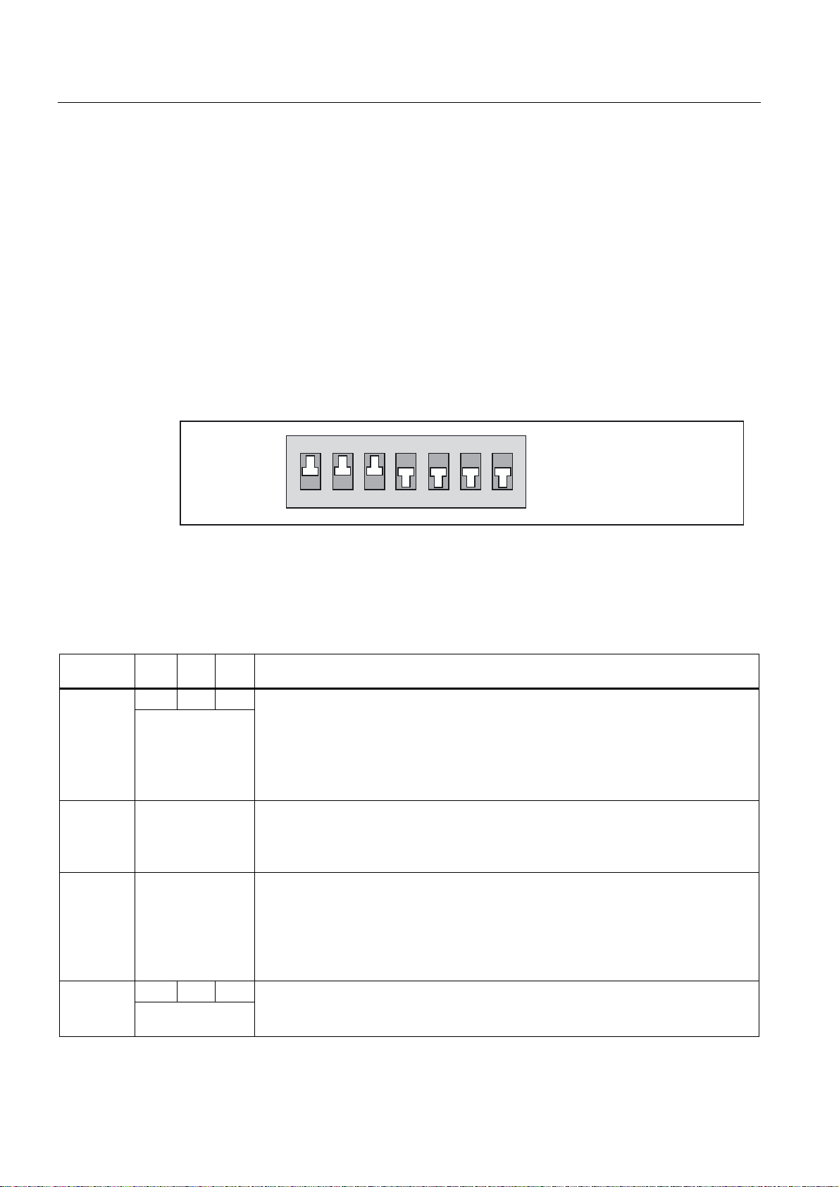
To set the SIMOTION operating mode, a binary code is used, which is entered via the DIL
switch (switch S1 - S3).
21
Figure 2-2 DIL switches
The following table contains the operating modes that can be set and the associated code.
Table 2-1 Mode selector switch settings
Operating
mode
STOPU 110 / 101 / 011
STOP 100 / 010 / 001
S1 S2 S3 Description
1 1 1 RUN
(3 switch = ON)
(2 switch = ON)
(1 switch = ON)
0 0 0 MRES
(0 switch = ON)
SIMOTION D410 runs the user program and all connected system performances:
• Read process image of inputs.
• Execution of the user programs assigned to the execution system.
• Write process image of outputs.
The technology packages are active in this state. They can execute commands from the
user program.
SIMOTION D410 does not run a user program.
• The technology packages are active. Test and commissioning functions can be
executed. The user program is not active.
• The I/O modules are in a secure state.
SIMOTION D410 does not run a user program.
• It is possible to load a complete user program.
• All system services (communications, etc.) are active.
• The I/O modules are in a secure state.
• The technology packages are inactive, i.e., all enables are deleted. No axis motions
can be executed.
Overall module reset
You can reset SIMOTION D410 via the MRES switch setting. Observe the operating
sequence in the Commissioning Manual,
SIMOTION D410
6ZLWFKVHWWLQJ 21
6ZLWFKVHWWLQJ 2))
, /1/.
D410
24 Manual, 03/2007 Edition

Operation (hardware)
2.2 Operator controls
Note
The factory DIL switch setting (switches S1 to S7) is 1110000. As a rule, it is not necessary
to adjust this switch. Use the SIMOTION SCOUT Engineering System to set the operating
mode (at switch setting 1110000).
Switches S4 - S7 are not used in SIMOTION D410 and must be set to "0" (OFF).
SIMOTION SCOUT mode selector switch
In SIMOTION SCOUT, you can control the SIMOTION D410 operating state using a
software switch.
To set the operating state via SIMOTION SCOUT, see the Configuring Manual,
SCOUT
, /9/.
2.2.2 SIMOTION CompactFlash card
CompactFlash card slot
The CompactFlash card (CF card) is inserted into the plug-in module over the blanking plate
(see "Overview of operator controls and indicators").
SIMOTION
CF card features
The CF card is mandatory to run SIMOTION D410. The CF card must be ordered as a
separate component; it is not included in the SIMOTION D410 scope of delivery.
The SIMOTION firmware is located on the CF card.
CF card functions:
• Backup technology packages and user data
• Update (e.g., SIMOTION firmware update)
Note
The CF card may only be unplugged and plugged in when the system is switched off
(zero current)!
If the CF card is being accessed, the RDY-LED on the SIMOTION D410 flashes green
(see chapter "Error and status indicators").
D410
Manual, 03/2007 Edition
25

Operation (hardware)
2.3 Error and status indicators
Further information
For more information on writing and formatting the CF card, see the Commissioning Manual,
SIMOTION D410, /1/
.
See also
System data, connection values, dimensions and weight (Page 62)
2.3 Error and status indicators
Arrangement of LED displays
The LED displays are located under the CF card plug-in module on the SIMOTION D410
(see "Overview of operator controls and indicators").
Further information
For the LED statuses, see the Commissioning Manual,
SIMOTION D410,
/1/.
D410
26 Manual, 03/2007 Edition
 Loading...