

Siemens SIMOTION C230-2 Equipment Manual

Preface, Table of Contents
SIMOTION
SIMOTION C230-2
Equipment Manual
Product Overview
The Fundamentals of Motion
Control
Device Data
Installation
Addressing the I/O
Wiring
Networking
Commissioning
Maintenance
1
2
3
4
5
6
7
8
9
6AU1 900-0AB30-0BA0
04.2003 Edition
Appendices
Standards and Approvals
EC Declaration of Conformity
ESD
References, Index
A
B
C

Safety notices
!
!
!
This manual contains notices that you should observe to ensure your own personal safety, as well as to
protect the product and connected equipment. These notices are highlighted in the manual by a warning
triangle and are marked as follows according to the level of danger:
Danger
Indicates a potentially hazardous situation which, if not avoided, will result in death or serious injury or in
substantial property damage.
Warning
Indicates a potentially hazardous situation which, if not avoided, could result in death or serious injury or
in substantial property damage.
Caution
Used with the safety alert symbol indicates a potentially hazardous situation which, if not avoided, may
result in minor or moderate injury or in property damage.
Caution
Used without the safety alert symbol indicates a potentially hazardous situation which, if not avoided, may
result in property damage.
Notice
Used without the safety alert symbol indicates a potential situation which, if not avoided, may result in an
undesirable result or state.
Qualified personnel
This device/system may only be set up and operated by qualified personnel. Qualified persons are defined as persons who are authorized to commission, to ground, and to tag circuits, equipment, and
systems in accordance with established safety practices and standards.
Correct usage
Note the following:
Warning
!
Trademarks
This device and its components may only be used for the applications described in the catalog or the
technical descriptions and only in connection with devices or components from other manufacturers that
have been approved or recommended by Siemens.
This product can only function correctly and safely if it is transported, stored, set up, and installed correctly, and operated and maintained as recommended.
SIMATICR, SIMATIC HMIR, SIMATIC NETR, and SIMOTIONR are registered trademarks of
SIEMENS AG.
Other names in this publication might be trademarks the use of which by a third party for his own purposes
may violate the rights of the registered holder.
Disclaimer of liabilityE Siemens AG, 2003 All rights reserved
The reproduction, transmission, or use of this document or its contents is not
permitted without express written authority. Offenders will be liable for
damages. All rights, including rights created by patent grant or registration of
a utility model or design, are reserved.
Siemens AG
Automation & Drives
Motion Control Systems
P.O. Box 3180, D-91050 Erlangen
Germany
-2
Siemens Aktiengesellschaft SIMOTION C230-2
We have checked the contents of this manual for agreement with the hardware and software described. Because deviations cannot be precluded entirely, we cannot guarantee full agreement. However, the data in this manual
are reviewed regularly, and any necessary corrections are included in subsequent editions. Suggestions for improvement are welcomed.
E Siemens AG, 2003
Subject to technical changes.
E Siemens AG, 2003 All rights reserved
SIMOTION C230-2, 04.2003 Edition

Preface
Sections of information in the manual
The following list describes the purpose of this manual and how you can benefit
from it.
S Product Overview (Chapter 1)
This part explains the purpose and potential applications of the module.
S The Fundamentals of Motion Control (Chapter 2)
Here you will find an introduction to motion control for individual axes and axis
groupings. The various terms are also explained.
S Device Data (Chapter 3)
This part introduces the C230-2 and its functions.
S Installation (Chapter 4)
This part explains the design of the mechanical configuration and how to install
the SIMOTION C230-2 components.
S Addressing the I/O (Chapter 5)
This part contains the information you will require to define the module initial
addresses of the modules used.
S Wiring (Chapter 6)
This part describes the connection and wiring for the drives, encoders and digital inputs/outputs (onboard).
S Networking (Chapter 7)
This part contains information that you need in order to create a PROFIBUS
subnet or Ethernet subnet.
S Commissioning (Chapter 8)
This part describes how you commission the hardware components and what
you must take into account.
S Maintenance (Chapter 9)
This part describes how you replace the module and update the SIMOTION
kernel.
S Appendices with factual information for reference (e.g. standards and approv-
als, ESD etc.)
E Siemens AG, 2003 All rights reserved
SIMOTION C230-2, 04.2003 Edition
Preface-3

Preface
S List of References
Here you can find an overview and list of all SIMOTION documentation which
you need for the configuration and commissioning of the C230-2.
S Glossary and index to find the information
Standards and approvals
Our products meet the requirements of EU directive 89/336/EEC “Electromagnetic
Compatibility” and the harmonized European Standards (EN) listed there.
You can find detailed information on approvals and standards in Appendix A.
The EC declaration of conformity in accordance with the above EU directive, Ar-
ticle 10, is contained in this manual (see Appendix B).
Recycling and disposal
SIMOTION C230-2 is an environmentally friendly product! It includes the following
features:
S In spite of its excellent resistance to fire, the flame-resistant agent in the plastic
used for the housing does not contain halogens.
S Identification of plastic materials in accordance with DIN 54840
S Less material used because the unit is smaller and with fewer components
thanks to integration in ASICs
The C230-2 can be recycled because it is low in pollutants.
For environmentally friendly recycling and disposal of your old modules in accor-
dance with most advanced techniques, please get in touch with your contact person. You can find the correct contact person under the following Internet address:
http://www.ad.siemens.de/partner
Contacts
Preface-4
If you have any problems or questions when working with this manual, please contact the Siemens department indicated on the remarks form at the end of this
manual.
E Siemens AG, 2003 All rights reserved
SIMOTION C230-2, 04.2003 Edition

Hotline
If you have any queries please contact our Hotline (worldwide):
A & D Technical Support: Phone: ++49-180-5050-222
If you have any comments on the documentation (suggestions, corrections),
please send them to the following fax number or e-mail address:
Fax form: See remarks form at the end of this document.
Additional support
We offer a range of courses to help you get started with the SIMOTION C230-2
system.
For more information, please contact your regional training center or the central
training center in D-90027 Nuremberg, Phone: ++49-911-895-3202.
Preface
Fax: ++49-180-5050-223
E-mail: ad.support@siemens.com
Fax: ++49-9131-98-2176
E-mail: motioncontrol.docu@erlf.siemens.de
Siemens Internet address
You can obtain constantly updated information on SIMOTION products on the
Internet at:
S General information http://www.siemens.de/simotion
S Technical information http://www4.ad.siemens.de/view/cs/en/10805436
E Siemens AG, 2003 All rights reserved
SIMOTION C230-2, 04.2003 Edition
Preface-5
Preface
Documentation for SIMOTION
SIMOTION Engineering
Order No.: 6AU1 900-0BA30-0BA0
SIMOTION Technology Functions
Order No.: 6AU1 900-0BE30-0BA0
SIMOTION Reference Lists
Order No.: 6AU1 900-0BF30-0BA0
SIMOTION Hardware
Order No.: 6AU1 900-0BB30-0BA0
SIMOTION Hardware consists of the following documents:
SIMOTION C230-2
Equipment Manual
SIMOTION Function Library
Order No.: 6AU1 900-0BC30-0BA0
SIMOTION Plastics
Order No.: 6AU1 900-0CX30-0BA0
6AU1 900-0CN30-0BA0
Y ou are here ...
SIMOTION Panels
Equipment Manual
SIMOTION P350
Equipment Manual
SIMOTION D435
Equipment Manual
ADI4 – Analog Drive Interface
for Four Axes
Equipment Manual
Preface-6
E Siemens AG, 2003 All rights reserved
SIMOTION C230-2, 04.2003 Edition

Table of Contents
1 Product Overview 1-11. . . . . . . . . . . . . . . . . . . . . . . . . . . . . . . . . . . . . . . . . . . . . . . . . . . . . .
2 The Fundamentals of Motion Control 2-17. . . . . . . . . . . . . . . . . . . . . . . . . . . . . . . . . . . .
3 Device Data 3-19. . . . . . . . . . . . . . . . . . . . . . . . . . . . . . . . . . . . . . . . . . . . . . . . . . . . . . . . . . . .
3.1 Layout of the module 3-20. . . . . . . . . . . . . . . . . . . . . . . . . . . . . . . . . . . . . . . . . . . .
3.1.1 Mode selector 3-24. . . . . . . . . . . . . . . . . . . . . . . . . . . . . . . . . . . . . . . . . . . . . . . . . .
3.1.2 Memory module slot 3-25. . . . . . . . . . . . . . . . . . . . . . . . . . . . . . . . . . . . . . . . . . . . .
3.1.3 Ethernet interface 3-25. . . . . . . . . . . . . . . . . . . . . . . . . . . . . . . . . . . . . . . . . . . . . . .
3.1.4 PROFIBUS DP and drive interface 3-27. . . . . . . . . . . . . . . . . . . . . . . . . . . . . . . .
3.1.5 I/O modules approved for SIMOTION 3-30. . . . . . . . . . . . . . . . . . . . . . . . . . . . . .
3.1.6 Analog drive interface 3-32. . . . . . . . . . . . . . . . . . . . . . . . . . . . . . . . . . . . . . . . . . . .
3.1.7 Measuring system interface 3-35. . . . . . . . . . . . . . . . . . . . . . . . . . . . . . . . . . . . . . .
3.1.8 I/O interface 3-41. . . . . . . . . . . . . . . . . . . . . . . . . . . . . . . . . . . . . . . . . . . . . . . . . . . .
3.2 Clock 3-46. . . . . . . . . . . . . . . . . . . . . . . . . . . . . . . . . . . . . . . . . . . . . . . . . . . . . . . . . .
3.3 Diagnosis using the LEDs 3-47. . . . . . . . . . . . . . . . . . . . . . . . . . . . . . . . . . . . . . . .
3.4 Technical data 3-51. . . . . . . . . . . . . . . . . . . . . . . . . . . . . . . . . . . . . . . . . . . . . . . . . .
3.5 Dimension drawing 3-55. . . . . . . . . . . . . . . . . . . . . . . . . . . . . . . . . . . . . . . . . . . . . .
3.6 Accessories and spare parts 3-56. . . . . . . . . . . . . . . . . . . . . . . . . . . . . . . . . . . . . .
4 Installation 4-57. . . . . . . . . . . . . . . . . . . . . . . . . . . . . . . . . . . . . . . . . . . . . . . . . . . . . . . . . . . . .
4.1 Design and configuration using SIMOTION C modules 4-58. . . . . . . . . . . . . . .
4.1.1 Horizontal and vertical configuration 4-58. . . . . . . . . . . . . . . . . . . . . . . . . . . . . . .
4.1.2 Clearances 4-59. . . . . . . . . . . . . . . . . . . . . . . . . . . . . . . . . . . . . . . . . . . . . . . . . . . . .
4.1.3 Mounting dimensions of modules 4-60. . . . . . . . . . . . . . . . . . . . . . . . . . . . . . . . . .
4.1.4 Layout of modules on a rack 4-61. . . . . . . . . . . . . . . . . . . . . . . . . . . . . . . . . . . . . .
4.1.5 Layout of modules on several racks 4-62. . . . . . . . . . . . . . . . . . . . . . . . . . . . . . . .
4.2 Installation 4-64. . . . . . . . . . . . . . . . . . . . . . . . . . . . . . . . . . . . . . . . . . . . . . . . . . . . .
4.2.1 Fitting the mounting rail 4-64. . . . . . . . . . . . . . . . . . . . . . . . . . . . . . . . . . . . . . . . . .
4.2.2 Installing modules on the mounting rail 4-67. . . . . . . . . . . . . . . . . . . . . . . . . . . . .
4.2.3 After installation 4-68. . . . . . . . . . . . . . . . . . . . . . . . . . . . . . . . . . . . . . . . . . . . . . . . .
5 Addressing the I/O 5-71. . . . . . . . . . . . . . . . . . . . . . . . . . . . . . . . . . . . . . . . . . . . . . . . . . . . . .
5.1 Assigning addresses on the basis of the module slot
(default addresses for centralized peripherals) 5-72. . . . . . . . . . . . . . . . . . . . . . .
5.2 User-assignable addressing on the C230-2
(centralized and distributed peripherals) 5-74. . . . . . . . . . . . . . . . . . . . . . . . . . . .
5.3 Addressing signal modules 5-75. . . . . . . . . . . . . . . . . . . . . . . . . . . . . . . . . . . . . . .
5.4 Addressing the integrated digital inputs and outputs of the C230-2 5-78. . . . .
E Siemens AG, 2003 All rights reserved
SIMOTION C230-2, 04.2003 Edition
Contents-7

Table of Contents
6 Wiring 6-79. . . . . . . . . . . . . . . . . . . . . . . . . . . . . . . . . . . . . . . . . . . . . . . . . . . . . . . . . . . . . . . . .
6.1 Project design of the electrical configuration 6-80. . . . . . . . . . . . . . . . . . . . . . . . .
6.2 Wiring diagram - Overview 6-82. . . . . . . . . . . . . . . . . . . . . . . . . . . . . . . . . . . . . . . .
6.2.1 Connecting the power supply 6-86. . . . . . . . . . . . . . . . . . . . . . . . . . . . . . . . . . . . .
6.2.2 Connecting the drive units 6-90. . . . . . . . . . . . . . . . . . . . . . . . . . . . . . . . . . . . . . . .
6.2.3 Connecting encoders 6-94. . . . . . . . . . . . . . . . . . . . . . . . . . . . . . . . . . . . . . . . . . . .
6.2.4 Wiring the front connector 6-96. . . . . . . . . . . . . . . . . . . . . . . . . . . . . . . . . . . . . . . .
6.3 Connecting shielded cables via a shield connecting element 6-99. . . . . . . . . . .
7 Networking 7-101. . . . . . . . . . . . . . . . . . . . . . . . . . . . . . . . . . . . . . . . . . . . . . . . . . . . . . . . . . . .
7.1 Designing a PROFIBUS subnet 7-101. . . . . . . . . . . . . . . . . . . . . . . . . . . . . . . . . . .
7.1.1 Requirements 7-101. . . . . . . . . . . . . . . . . . . . . . . . . . . . . . . . . . . . . . . . . . . . . . . . . . .
7.1.2 Rules for designing a subnet 7-102. . . . . . . . . . . . . . . . . . . . . . . . . . . . . . . . . . . . . .
7.1.3 Cable lengths 7-105. . . . . . . . . . . . . . . . . . . . . . . . . . . . . . . . . . . . . . . . . . . . . . . . . . .
7.2 Network components for PROFIBUS subnet 7-106. . . . . . . . . . . . . . . . . . . . . . . .
7.2.1 PROFIBUS bus cable 7-106. . . . . . . . . . . . . . . . . . . . . . . . . . . . . . . . . . . . . . . . . . . .
7.2.2 Bus connector 7-107. . . . . . . . . . . . . . . . . . . . . . . . . . . . . . . . . . . . . . . . . . . . . . . . . .
7.2.3 Plugging the bus connector into the module 7-108. . . . . . . . . . . . . . . . . . . . . . . . .
7.3 Ethernet subnet 7-109. . . . . . . . . . . . . . . . . . . . . . . . . . . . . . . . . . . . . . . . . . . . . . . . .
7.4 MPI subnet 7-110. . . . . . . . . . . . . . . . . . . . . . . . . . . . . . . . . . . . . . . . . . . . . . . . . . . . .
8 Commissioning 8-111. . . . . . . . . . . . . . . . . . . . . . . . . . . . . . . . . . . . . . . . . . . . . . . . . . . . . . . .
8.1 Prerequisites for commissioning 8-112. . . . . . . . . . . . . . . . . . . . . . . . . . . . . . . . . . .
8.2 Inserting and changing the Micro Memory Card 8-114. . . . . . . . . . . . . . . . . . . . . .
8.3 Switching on for the first time 8-115. . . . . . . . . . . . . . . . . . . . . . . . . . . . . . . . . . . . .
8.4 Writing, formatting and erasing the Micro Memory Card 8-116. . . . . . . . . . . . . . .
8.5 Performing an overall reset on the C230-2 8-118. . . . . . . . . . . . . . . . . . . . . . . . . .
8.6 User memory concept 8-120. . . . . . . . . . . . . . . . . . . . . . . . . . . . . . . . . . . . . . . . . . .
8.7 Resetting the C230-2 to the default setting as delivered 8-123. . . . . . . . . . . . . .
9 Maintenance 9-125. . . . . . . . . . . . . . . . . . . . . . . . . . . . . . . . . . . . . . . . . . . . . . . . . . . . . . . . . . .
9.1 SIMOTION Kernel update 9-126. . . . . . . . . . . . . . . . . . . . . . . . . . . . . . . . . . . . . . . .
9.2 Removing and exchanging the C230-2 9-127. . . . . . . . . . . . . . . . . . . . . . . . . . . . .
9.3 Module exchange without PG/PC 9-129. . . . . . . . . . . . . . . . . . . . . . . . . . . . . . . . . .
A Standards and Approvals A-131. . . . . . . . . . . . . . . . . . . . . . . . . . . . . . . . . . . . . . . . . . . . . . .
A.1 Electromagnetic compatibility A-132. . . . . . . . . . . . . . . . . . . . . . . . . . . . . . . . . . . . .
A.2 Shipping and storage conditions for the C230-2 A-135. . . . . . . . . . . . . . . . . . . . .
A.3 Mechanical and climatic environmental conditions for the operation
of the C230-2 A-135. . . . . . . . . . . . . . . . . . . . . . . . . . . . . . . . . . . . . . . . . . . . . . . . . . .
A.4 Details of insulation testing, safety class and degree of protection A-138. . . . . .
A.5 Rated voltage to operate the C230-2 A-138. . . . . . . . . . . . . . . . . . . . . . . . . . . . . . .
A.6 Safety of electronic controls A-138. . . . . . . . . . . . . . . . . . . . . . . . . . . . . . . . . . . . . .
E Siemens AG, 2003 All rights reserved
Contents-8
SIMOTION C230-2, 04.2003 Edition

Table of Contents
B EC Declaration of Conformity B-141. . . . . . . . . . . . . . . . . . . . . . . . . . . . . . . . . . . . . . . . . . .
C Directive for the Handling of Electrostatically Sensitive Devices (ESD) C-145. . . . .
C.1 What does ESD mean? C-145. . . . . . . . . . . . . . . . . . . . . . . . . . . . . . . . . . . . . . . . . .
C.2 Electrostatic discharge from persons C-146. . . . . . . . . . . . . . . . . . . . . . . . . . . . . . .
C.3 Basic measures to protect against the discharge of static electricity C-147. . . .
References References-149. . . . . . . . . . . . . . . . . . . . . . . . . . . . . . . . . . . . . . . . . . . . . . . . . . . .
Index Index-157. . . . . . . . . . . . . . . . . . . . . . . . . . . . . . . . . . . . . . . . . . . . . . . . . . . . . . . . . . . . . . .
E Siemens AG, 2003 All rights reserved
SIMOTION C230-2, 04.2003 Edition
Contents-9

Table of Contents
Contents-10
E Siemens AG, 2003 All rights reserved
SIMOTION C230-2, 04.2003 Edition

Product Overview
What can the C230-2 do?
The C230-2 is a motion control module for controlling servo drives via PROFIBUS
DP and four onboard drive interfaces.
The following configurations can be selected:
S Four axes via the onboard drive interface or
S Axes via PROFIBUS DP or
S Mixed operation with a maximum of four axes via the onboard drive interface
and axes via PROFIBUS DP
The number of operable axes on the PROFIBUS DP depends on the set system
cycle clocks, i.e. more than four axes can be operated with longer cycle times.
The C230-2 is a powerful module for positioning independent, single axes or motions in an axis grouping.
Both rotary axes and linear axes can be operated.
The configuration, parameterization, commissioning, programming and diagnostics
of the C230-2 is carried out via the Engineering System (ES).
1
For which applications can the C230-2 be used?
The C230-2 can be used both for positioning and synchronous operation (gearbox
and cam).
Typical areas in which the motion control module can be used are:
S Packaging industry
S Plastics industry
S Presses
S Textile industry
S Printing industry
S Wood, glass, ceramic, stone
E Siemens AG, 2003 All rights reserved
SIMOTION C230-2, 04.2003 Edition
1-11
Product Overview
System integration
SIMOTION offers an optimized system platform for automation and drive solutions
where priority is given to motion control applications and technological tasks.
The SIMOTION modular system consists of the Engineering System SIMOTION
SCOUT and a shared runtime system for various hardware platforms.
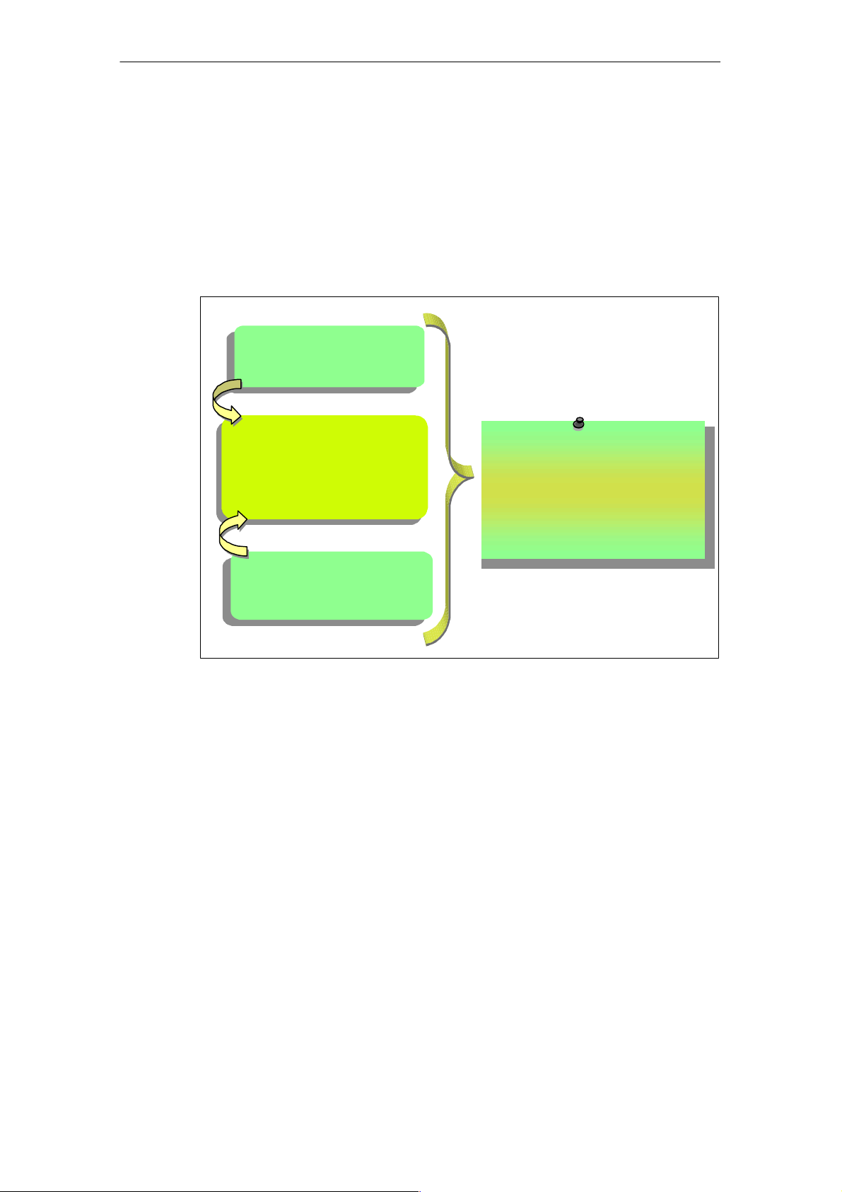
The truly innovative aspect of SIMOTION is that it does away with the traditional
separation between pure automation functions and motion functions.
Logic
Motion control
(e.g. positioning,
synchronous operation,...)
The system approach of
SIMOTION
The fusion of motion control, logic
and other technology functions.
Further technology
functions
(e.g. pressure control,
temperature control)
Fig. 1-1 System solution for production machines
Individual automation tasks for production machines are formulated in a uniform
and consistent user interface. Logic and motion functions are programmed in this
graphic programming tool. The logic commands can also be programmed using the
structured text (ST) high-level language that complies with IEC 1131.
Technological tasks such as positioning or synchronous operation are available as
functions that are simple for you to incorporate in the program, as are the logic
commands too.
1-12
Consistency in the three areas of programming and project design, data management and communication is the core feature of Totally Integrated Automation (TIA).
E Siemens AG, 2003 All rights reserved
SIMOTION C230-2, 04.2003 Edition
Product Overview
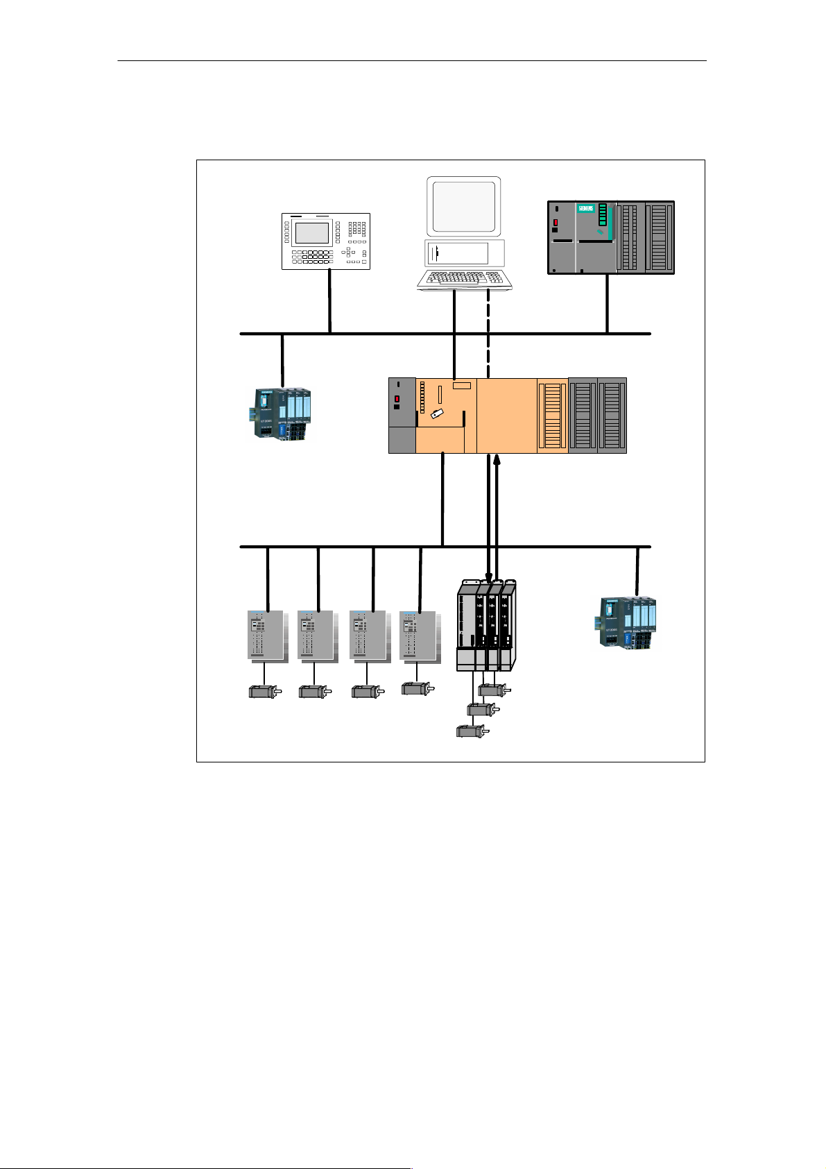
The following figure shows a system configuration with SIMOTION C230-2.
SIMATIC
HMI device
PROFIBUS DP
ET 200
PROFIBUS DP (isochronous)
PG/PC
PS
SIMATIC
S7
Ethernet
C230-2 SMs
S7-300
Fig. 1-2 System overview
ET 200
E Siemens AG, 2003 All rights reserved
SIMOTION C230-2, 04.2003 Edition
1-13

Product Overview
Components
The most important components of a SIMOTION application with C230-2 and their
functions are listed below.
Note
The modules or devices approved for the C230-2 can be found in the SIMOTION
PM 10 catalog.
Refer to the list of references for the order number of the catalog.
Centralized peripherals
Table 1-1 C230-2 with centralized peripherals
Component
C230-2 ... is the motion control module. The C230-2 supplies the P-bus
with 5 V; communicates over the P-bus (backplane bus) with
the I/O modules.
You can use the C230-2’s integrated fast digital inputs/outputs
as:
Function
S Homing inputs
S Inputs for measuring inputs
S User-addressable process inputs/outputs
Drive devices with "10 V analog interfaces can be connected
to the onboard drive interface.
Incremental encoders or absolute encoders can be connected
to the measuring system interface.
Power supply (PS) ... converts the line voltage (120/230 VAC) into an operating
voltage of 24 VDC to supply the C230-2.
Signal modules (SM) ... adapt various process signal levels to the C230-2 (digital
input/output modules and analog input/output modules).
Note:
All approved modules are listed in the PM 10 catalog and in
Subsection 3.1.5.
Function modules (FM) ...relieve the CPU of computation-intensive tasks, for example,
counting.
Note:
All approved modules are listed in the PM 10 catalog and in
Subsection 3.1.5.
Communications processors (CP)
... for data exchange
Note:
All approved modules are listed in the PM 10 catalog and in
Subsection 3.1.5.
1-14
E Siemens AG, 2003 All rights reserved
SIMOTION C230-2, 04.2003 Edition

Distributed I/Os
Table 1-2 C230-2 with distributed I/Os
Product Overview
Component
C230-2 ... is the motion control module.
Function
S The C230-2 communicates via two PROFIBUS DP inter-
faces with the:
– Programming device (PG/PC)
– SIMATIC HMI devices
– S7 controllers with PROFIBUS DP interface
– I/O systems ET 200
– Drive units
– Further C230-2s
S The C230-2 communicates via an Ethernet interface with
the programming device (PG/PC).
Note:
All approved devicles are listed in the PM 10 catalog and in
Subsection 3.1.5.
Table 1-3 Further components that can be connected to the C230-2
Component
Programming device
(PG/PC)
... configures, parameterizes, programs and tests SIMOTION
and C230-2.
Function
SIMATIC HMI device ... is used for operating and monitoring functions. It is not abso-
lutely essential for the operation of a C230-2.
Note:
All released modules are listed in the PM 10 catalog.
Drive units ... convert speed setpoints into signals for controlling the motor
and provide the power required to operate the motors.
Note:
All released modules are listed in the PM 10 catalog.
E Siemens AG, 2003 All rights reserved
SIMOTION C230-2, 04.2003 Edition
1-15

Product Overview
1-16
E Siemens AG, 2003 All rights reserved
SIMOTION C230-2, 04.2003 Edition

The Fundamentals of Motion Control
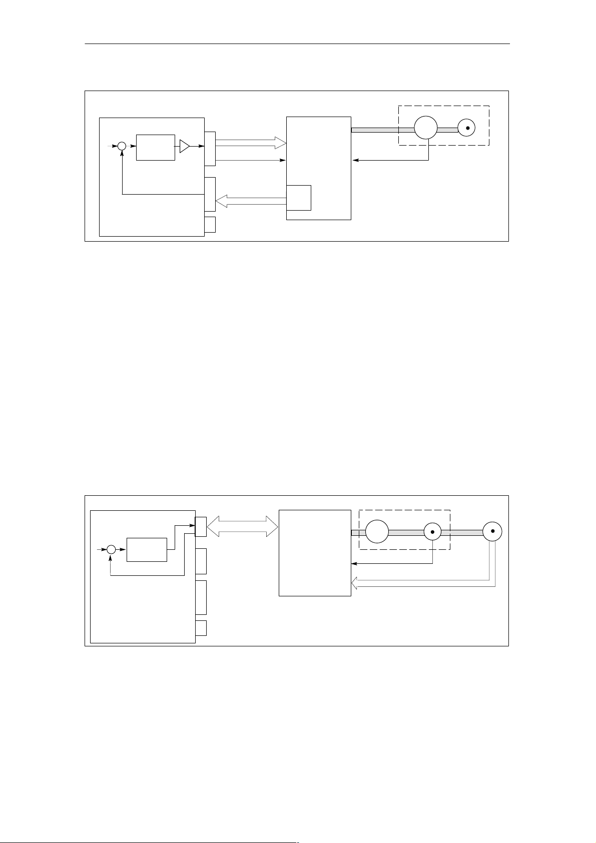
Position-controlled motion control for servo axes (onboard I/Os)
The C230-2 allows the position-controlled motion control of up to four axes. The
C230-2 provides an analog output for the speed setpoint for each axis and an
encoder input for the cyclic sensing of the actual position value.
2
C230-2
X2
X3
X4
X5
X6
X1
Speed
setpoint
Enable
+
Fig. 2-1 Servo system with converter, e.g. SIMODRIVE 611 analog, with external incremental encoder
–
Position
controller
DAC
Converter
Power section
Current controller
Speed controller
Actual position value, zero mark
Servo motor
M
3
Actual speed value
Encoder
Incremental encoder
Encoders are generally connected for position measurement. These supply
counting pulses, according to their resolution, for the incremental distance
travelled. They can be either rotary or linear.
A “homing” (referencing) operation must be performed in order to determine the
absolute position reference.
Absolute encoder (SSI)
Instead of conventional incremental encoders, which supply only one dimension for
the distance travelled, absolute encoders with a serial interface can be connected.
No homing operation need be performed for these encoders as they always supply
the absolute position as an actual value.
A one-off adjustment of the absolute encoder is required when the machine is initially commissioned.
E Siemens AG, 2003 All rights reserved
SIMOTION C230-2, 04.2003 Edition
2-17
The Fundamentals of Motion Control
C230-2
+
–
Position
controller
DAC
Speed setpoint
X2
Enable
Actual position
X3
X4
value, zero mark
X5
X6
X1
Converter
Power section
Current controller
Speed controller
WSG
Rotor position
Servo motor
M
3
Encoder
Fig. 2-2 Servo system with converter, e.g. SIMODRIVE 611 universal, with encoder emulation
Encoder emulation
Modern motor/converter systems often have a high-resolution motor measuring
system (rotor position encoder) connected at the converter. Here the converter
provides the position information via an interface that emulates an incremental encoder (e.g. incremental shaft encoder (WSG) interface with SIMODRIVE). A separate position measuring system is not required in this case.
Position-controlled motion control for servo axes (PROFIBUS DP)
The C230-2 allows the position-controlled motion of axes via PROFIBUS DP.
The following PROFIBUS protocol is used for specifying the speed setpoint and
feeding back the actual position value:
PROFIdrive profile drive technology, Version 3 (isochronous)
C230-2
Converter
Speed setpoint
X9
PROFIBUS DP
+
Position
controller
–
Actual position value
X2
X3
X4
X5
X6
X1
Power section
Current controller
Speed controller
Fig. 2-3 Servo system with converter, e.g. SIMODRIVE 611 universal
Servo motor
M
3
Actual speed value
Actual position value, zero mark
Encoder
2-18
E Siemens AG, 2003 All rights reserved
SIMOTION C230-2, 04.2003 Edition

Device Data
Overview
This chapter contains information on:
S Layout of the module
S Mode selector
S Memory module slot
S PROFIBUS DP and drive interface
S Analog drive interface
S Measuring system interface
S I/O interface
S Clock
S Diagnosis using the LEDs
S Technical data
S Dimension drawing
3
S Accessories and spare parts
E Siemens AG, 2003 All rights reserved
SIMOTION C230-2, 04.2003 Edition
3-19
Device Data
3.1 Layout of the module
View of C230-2
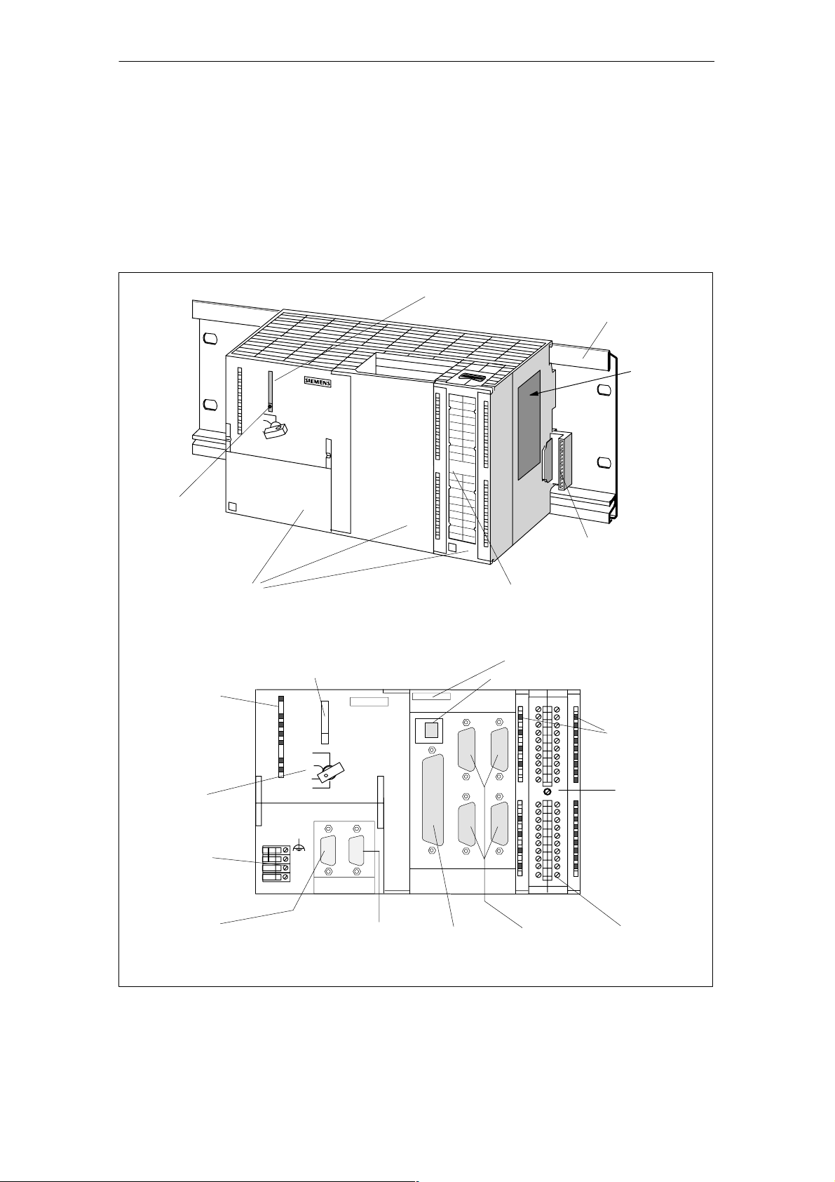
Fig. 3-1 shows the C230-2 module, indicating the interfaces and components on
the front panel (fault and status displays).
Micro Memory Card (MMC)
Mounting rail
Rating plate
Ejector for
Micro Memory Card
Front covers
(hinged)
Fault and
status displays
Mode selector
Connection for
power supply
X10
Memory module slot for
micro memory card
SF
5 VDC
RUN
STOPU
STOP
BUS1F
BUS2F
24 VDC
C230-2
RUN
STOPU
STOP
MRES
M
L+
M
X8 DP1
SIEMENS
X9 DP2/MPI
Labeling plate
Front view
without front covers
X3 X4
X7
X2
X5 X6
Bus connector
for P-bus
Ethernet address (MAC address)
Ethernet interface X7
Status displays
dig. inputs/outputs
X1
Front connector
PROFIBUS DP1
interface X8
PROFIBUS DP2/MPI
interface X9
Drive
interface X2
Fig. 3-1 Position of interfaces and front panel components
3-20
Measuring system
interfaces X3...X6
E Siemens AG, 2003 All rights reserved
SIMOTION C230-2, 04.2003 Edition
I/O
interface X1

Interfaces
Device Data
The interfaces and their functions are described in Table 3-1.
Table 3-1 Interfaces
Interfaces
Bus connector A rear-mounted connector for connecting the C230-2 with
other S7-modules over the P-bus
Drive interface 50-pin Sub-D connector X2 for the analog connection of
drives (max. 4 axes)
See Subsection 3.1.6
Measuring system interface 15-pin Sub-D sockets X3 to X6 for connection of encoders
(max. 4)
See Subsection 3.1.7
I/O interface 40-pin front connectors X1 for connecting the fast digital
inputs/outputs including measuring inputs, BEROs, and for
wiring the READY relay
See Subsection 3.1.8
Power supply connection 4-pin screw-type terminal connection X10 for connecting
the 24 V load power supply
See Subsection 6.2.1
Memory module slot 7-pin connector for Micro Memory Card
See Subsection 3.1.2
PROFIBUS DP1 interface 9-pin Sub-D socket X8 for connection to the PROFIBUS
DP. This interface can be used for isochronous operation.
See Subsection 3.1.4
PROFIBUS DP2/MPI
interface
Ethernet interface 8-pin RJ45 socket X7 for connection to a Fast Industrial
9-pole X9 Sub-D socket for connection to PROFIBUS DP
(default setting) or an MPI bus.
This interface can be used for isochronous operation.
See Subsection 3.1.4
Ethernet
Description
E Siemens AG, 2003 All rights reserved
SIMOTION C230-2, 04.2003 Edition
3-21

Device Data
Display of LEDs
The following LEDs are on the front panel of the C230-2. The LEDs and their function are described in Table 3-2.
Table 3-2 Status and fault displays
LED
SF (red) This LED indicates a fault on the C230-2.
(See Section 3.3)
5 VDC (green) This LED indicates that the power supply for the electronics is
ready.
(See Section 3.3)
RUN (green) C230-2 in RUN
STOPU (yellow) –
C230-2 in STOP User
Program
STOP (yellow) –
C230-2 in STOP
BUS1F (red) –
group fault
BUS2F (red) –
group fault
Q0...Q7, I0...I1 1,
B1...B4, M1, M2 (green) –
digital inputs/outputs
This LED indicates that the user program is running.
(See Section 3.3)
This LED indicates that the technology packages (e.g.
synchronous operation, cam) are active. The user program is
not active.
(See Section 3.3)
This LED indicates that no user program is running. The
technology packages are not active.
(See Section 3.3)
This LED indicates a fault on the C230-2’s PROFIBUS DP1
interface (X8).
(See Section 3.3)
This LED indicates a fault on the C230-2’s PROFIBUS DP2
/MPI interface (X9).
(See Section 3.3)
These LEDs show the status of the digital inputs/outputs.
(See Subsection 3.1.8)
Function
Control elements
Mode selector
Certain operating modes can be selected using the mode selector (see Subsec-
tion 3.1.1).
3-22
E Siemens AG, 2003 All rights reserved
SIMOTION C230-2, 04.2003 Edition
Rating plate
Device Data
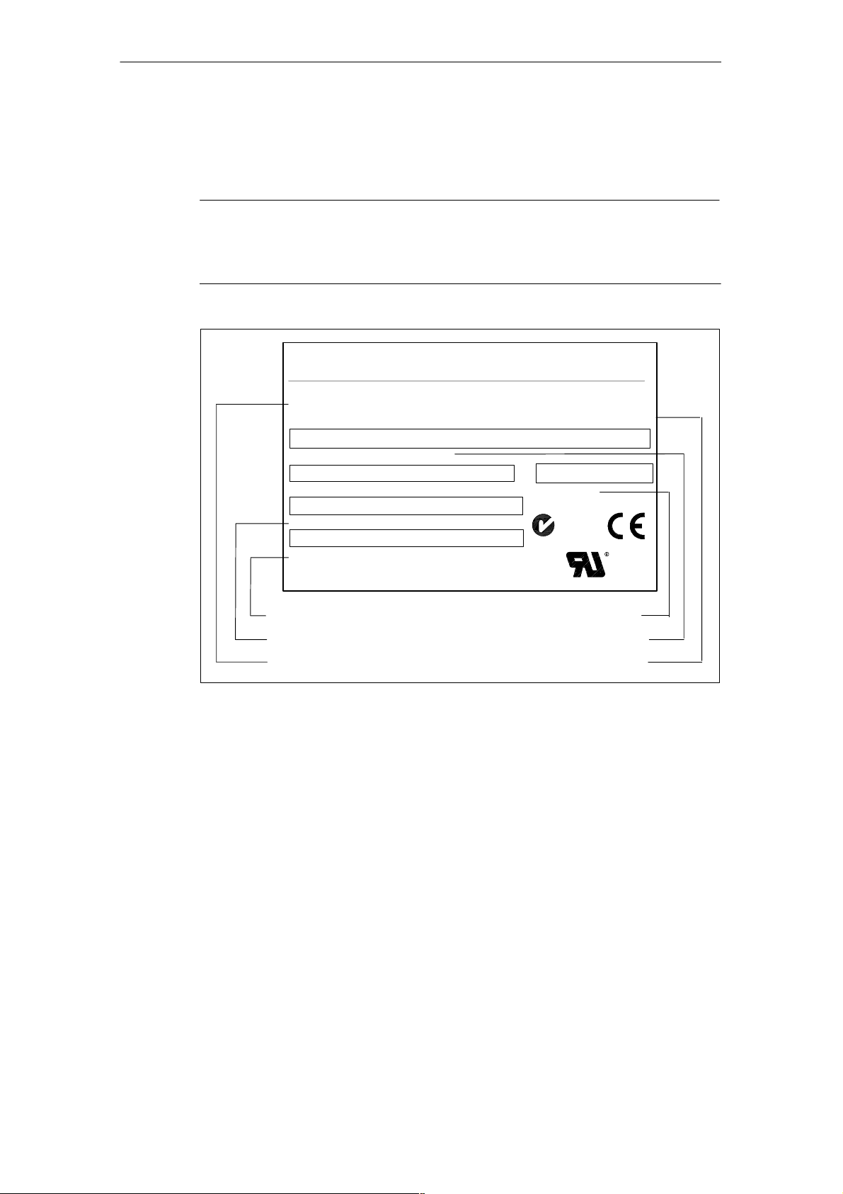
Fig. 3-2 explains all the information on the rating plate.
Note
The information contained in the individual fields of the rating plate on the actual
module may differ from the information described in this manual (e.g. enhanced
product development, authorizations and designations not yet granted, etc.).
SIEMENS
C230-2
AXIS CONTROL
Barcode order no. (1P6AU1230-2AA00-0AA0)
6AU1230-2AA00-0AA0
1P
Barcode product no. (A5E00128707)
A5E00128707
Barcode serial no. (ST-P12345678)
S T-P12345678
MAC address bar code (000000000000)
000000000000
Made in Germany
MAC address
Serial number
Module name
Fig. 3-2 Rating plate for the C230-2
INPUT 24 VDC, 2 A
8DO 24 VDC/0.25 A/0.5 A; 18DI 24 VDC
SIMOTION
Version bar code
Vers.: A
N117
CUS
Product version
Order number
Connection parameters
E Siemens AG, 2003 All rights reserved
SIMOTION C230-2, 04.2003 Edition
3-23

Device Data
3.1.1 Mode selector
Mode selector positions
The positions of the mode selector are explained in the sequence in which they are
arranged on the C230-2.
Table 3-3 Mode selector positions
Position
RUN
STOPU
STOP
MRES
(overall reset)
Explanations
The C230-2 is executing the user program (UP) and the associated system functions:
S Reading process image of inputs
S Processing user programs assigned to the execution system
S Writing process image of outputs
The technology packages are active in this state. They can execute
commands from the user program.
The key cannot be removed in this position.
The C230-2 is not executing a user program.
S The technology packages are active. Test and commissioning func-
tions can be executed. The user program is not active.
S The I/O modules (SMs) are in a secure state.
In this position the key can be removed so that no unauthorized person
can change the operating modes.
S The C230-2 is not executing a user program.
S It is possible to load a complete user program.
S All system services (communications, etc.) are active.
S The I/O modules (SMs) are in a secure state.
S The technology packages are inactive, i.e. all enables are deleted.
No axis movements can be executed.
In this position, the key can be removed so that no unauthorized person
can change the operating modes.
S Setting for overall reset on the C230-2
A specific sequence of operations is required to perform an overall
reset using the mode selector (see Section 8.5).
S Setting for Micro Memory Card formatting
Micro Memory Card formatting see Section 8.4
3-24
E Siemens AG, 2003 All rights reserved
SIMOTION C230-2, 04.2003 Edition

3.1.2 Memory module slot
7-pin connector to plug in a Micro Memory Card (MMC)
Micro Memory Card
The following Micro Memory Card is available:
Order no.: 6AU1 700-0AA01-0AA0
The Micro Memory Card can be used:
S To save the SIMOTION Kernel (base system) in order to carry out an update
(see Section 9.1)
The SIMOTION Kernel should always be stored on the Micro Memory Card.
S To save the technology packages and user data (programs, configuration data,
parameterization)
Device Data
3.1.3 Ethernet interface
Interface for connecting a Fast Industrial Ethernet.
Fast Industrial Ethernet is a communication network with a transmission rate of
10/100 Mbit/s.
The C230-2 offers the following functions via the Ethernet interface:
S Communications with STEP 7 and SIMOTION SCOUT
The “SIMATIC NET SOFTNET-PG (Protocol TPC/IP RFC 1006)” software must
be installed on the PG/PC for this function.
S Communications between SIMOTION and SIMATIC NET OPC
The “SIMATIC NET SOFTNET-S7 (S7-OPC-Server)” software must be installed
on the PG/PC for this function.
Note:
SOFTNET-S7 is a superset of SOFTNET-PG, i.e. SOFTNET-S7 also contains
this Protocol TPC/IP RFC 1006.
For further information about the software packages, see Motion Control System
SIMOTION, PM 10 catalog, see List of References for the order number.
Connectable devices
A PG/PC can be connected to the Ethernet interface via a Fast Ethernet network.
The PG must be equipped with an Ethernet card and the corresponding software
must be available.
E Siemens AG, 2003 All rights reserved
SIMOTION C230-2, 04.2003 Edition
3-25
Device Data
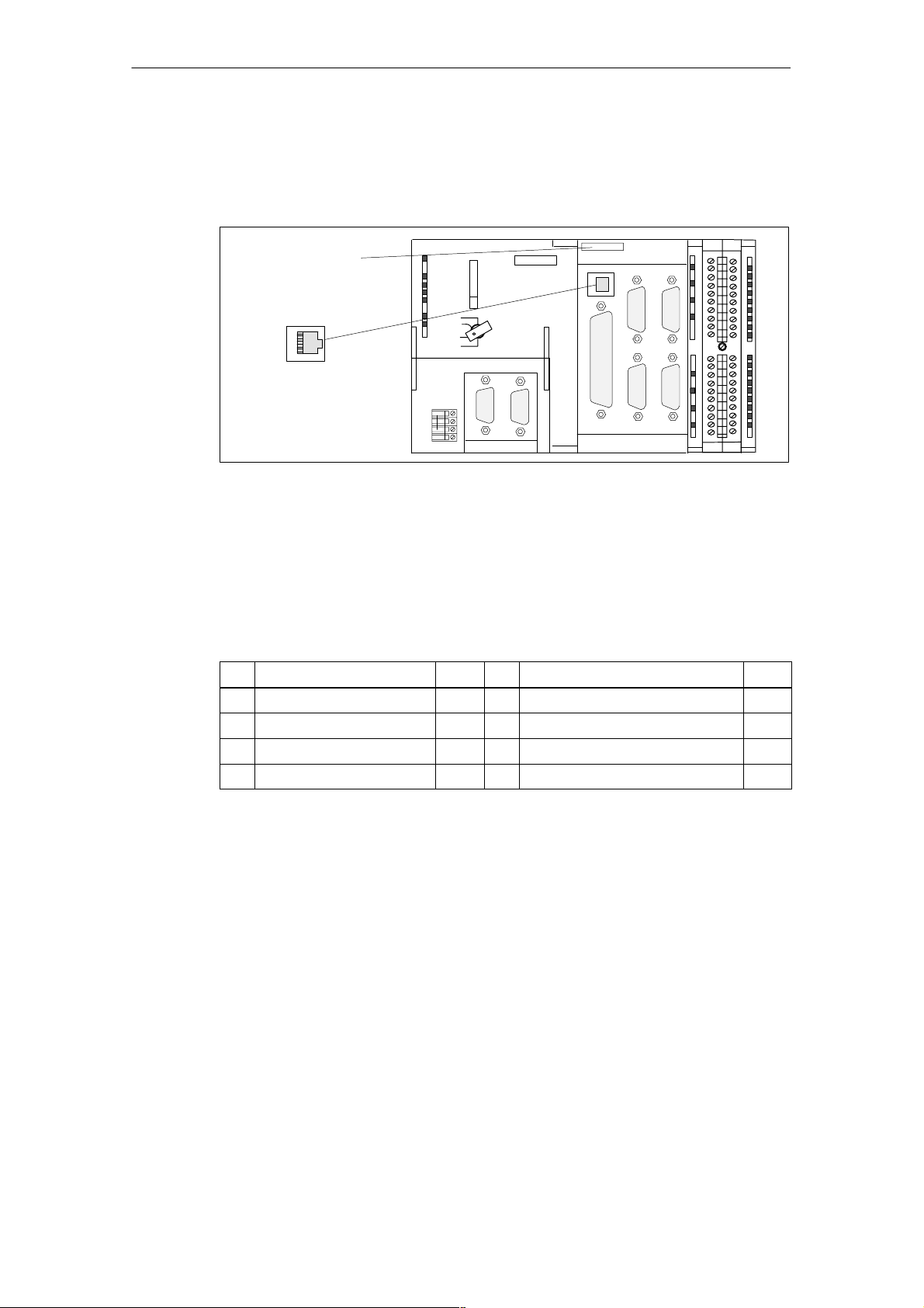
Position of the connectors
Fig. 3-4 shows the installation position and the designation of the connector on the
module.
Ethernet address
(MAC address)
(e.g. 08000673238B)
X7
8
1
Fig. 3-3 Position of connector X7
Connector pin assignment
Designation: X7 (Ethernet)
Type: 8-pin RJ45 socket
Table 3-4 Assignment of X7 connector
Pin
1 TDP O 5 Unassigned
2 TDM O 6 RDM I
3 RDP I 7 Unassigned
4 Unassigned 8 Unassigned
X3 X4
C230-2
X8 DP1
SIEMENS
X9 DP2/MPI
X7
X1
X2
X6X5
Name Type Pin Name Type
Signal names RDP, RDM Receive Data +/–
TDP, TDM Transmit Data +/–
Signal type I Signal input
O Signal output
3-26
E Siemens AG, 2003 All rights reserved
SIMOTION C230-2, 04.2003 Edition

3.1.4 PROFIBUS DP and drive interface
PROFIBUS DP interface (X8, X9)
The C230-2 provides you with two interfaces for connection to the PROFIBUS DP.
Baud rates up to 12 Mbits/s are possible. Both interfaces can be used for isochronous operation.
The interfaces can be operated in the following combinations as master or slave
(isochronous/not isochronous):
Device Data
X8 X9 Remark
DP slave
isochronous
DP master
isochronous
DP slave
isochronous
DP master not
isochronous
DP master
isochronous
DP master
isochronous
DP master
isochronous
DP master not
isochronous
DP slave not
isochronous
DP master not
isochronous
DP slave not
isochronous
DP master not
isochronous
DP master
isochronous
DP slave
isochronous
DP master not
isochronous
DP slave
isochronous
DP master
isochronous
DP master not
isochronous
DP slave not
isochronous
DP master
isochronous
DP master
isochronous
DP master not
isochronous
DP master not
isochronous
DP slave not
isochronous
Application synchronized with
DP master (X9), application
controls synchronization with
DP slave (X8)
Application synchronized with
DP master (X8), application
controls synchronization with
DP slave (X9)
Application running freely or
synchronized to the DP slave
(X8)
(can be monitored by the application)
Application running freely or
automatically synchronized to
the DP slave (X9)
(can be monitored by the application)
Application synchronized with
DP master (X8, X9)
Application synchronized with
DP master (X8)
Application synchronized with
DP master (X8)
Application synchronized with
DP master (X9)
Application synchronized with
DP master (X9)
Application asynchronous None
Application asynchronous None
Application asynchronous None
Actions in the
application
DP master/DP slave
synchronization mechanisms
DP master/DP slave
synchronization mechanisms
DP slave synchronization mechanisms
DP slave synchronization mechanisms
None
None
None
None
None
1)
1) Actions in the application see function description SIMOTION Modular Machine Con-
cepts, order no. see List of References
E Siemens AG, 2003 All rights reserved
SIMOTION C230-2, 04.2003 Edition
3-27

Device Data
If both interfaces (X8, X9) are to be operated isochronously, then they must both
be configured with the same DP cycle clock.
The X9 can alternatively be used as an MPI interface with a baud rate of up to
12 MBit/s.
Connectable devices
The following devices can be connected to the PROFIBUS DP interfaces:
S PG/PC
S SIMATIC HMI devices
S S7 controllers with PROFIBUS DP interface
S Distributed I/Os (e.g. ET 200M)
The updating of the digital inputs/outputs is carried out in the position control
cycle clock.
S C230-2
S Teleservice adapter
S Drives with digital interface (e.g. SIMODRIVE 611 universal)
Note
A teleservice adapter can only be connected to one of the two interfaces.
All approved modules and devices are listed in the PM 10 catalog and in Subsec-
tion 3.1.5. Refer to the list of references for the order number.
Please note the documentation regarding the individual modules or devices!
3-28
E Siemens AG, 2003 All rights reserved
SIMOTION C230-2, 04.2003 Edition
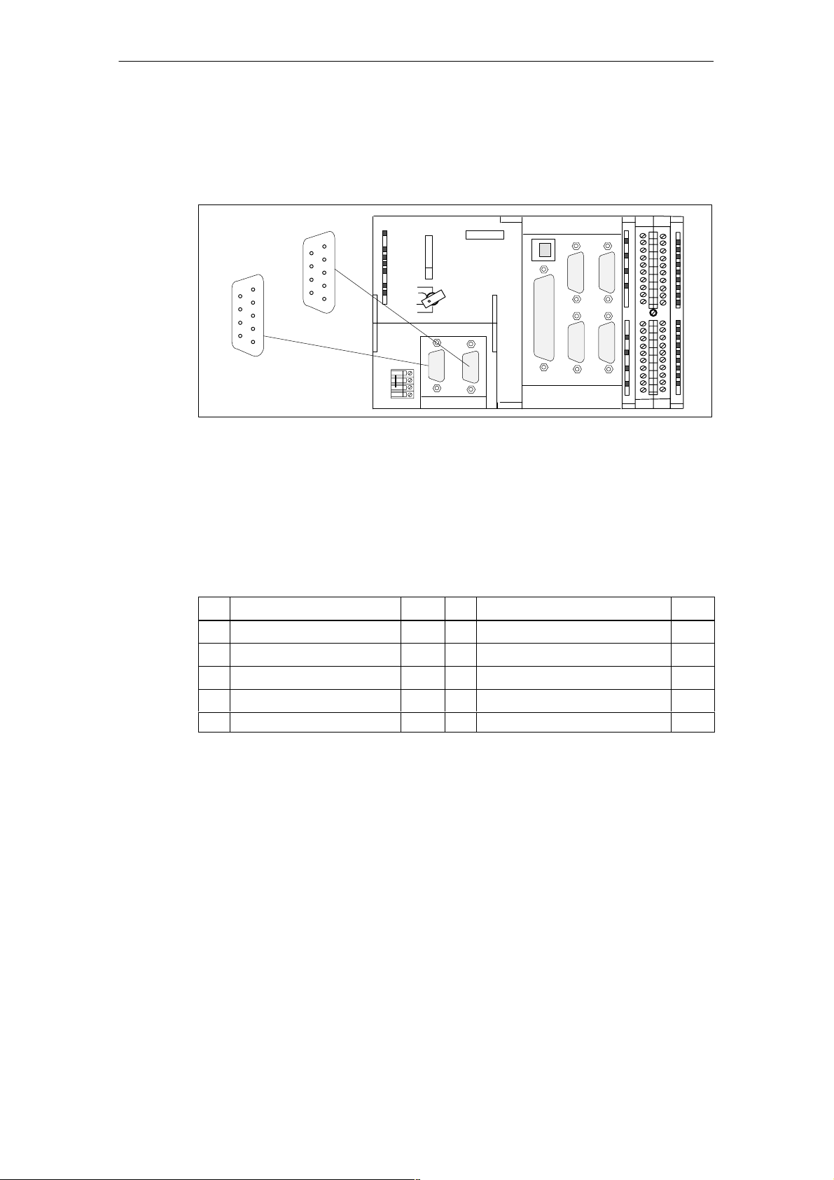
Position of the connectors
Fig. 3-4 shows the mounting position and designation of the connectors on the
module.
Device Data
DP1
5
9
6
1
X8
Fig. 3-4 Position of connectors X8, X9
Connector pin assignment
Designation: X8, X9 DP1, DP2/MPI
Type: 9-pin Sub-D socket
Table 3-5 Assignment of X8, X9 connector
Pin
1 Unassigned 6 P5 VO
2 M24 VO 7 P24 VO
3 B I/O 8 A I/O
4 RTS I 9 Unassigned
5 GND VO
DP2/MPI
5
9
6
1
C230-2
SIEMENS
X3 X4
X7
X1
X9
X9 DP2/MPIX8 DP1
X2
X6X5
Name Type Pin Name Type
Signal names A, B Data input/output (RS485)
RTS Request to send
P5 5 V supply 60 mA, short-circuit-proof
GND Ground for 5 V voltage
P24 24 V supply 150 mA, short-circuit-proof, not isolated
M24 24 V reference potential
Signal type I Signal input
I/O Signal input/output
VO Voltage output
E Siemens AG, 2003 All rights reserved
SIMOTION C230-2, 04.2003 Edition
3-29

Device Data
3.1.5 I/O modules approved for SIMOTION
Preferred peripherals for use with SIMOTION C:
S Centralized peripherals:
SIMATIC S7-300 I/O modules (only with SIMOTION C)
S Distributed I/O systems:
– SIMATIC ET 200M (distributed use of SIMATIC S7-300 I/O modules):
The modular I/O system for control cabinet installation and high channel
densities
– SIMATIC ET 200S:
Fine modular I/O system for control cabinet installation including motor starters, safety technology and individual grouping of the load groups
– SIMATIC ET 200X:
The modular I/O system in the IP 65/67 degree of protection for use without
a control cabinet and in the machine’s proximity; includes motor starters and
pneumatic modules as well as DESINA- and ECOFAST-conform modules
– SIMATIC ET 200eco:
The compact, economical I/O system in the IP 67 degree of protection for
use without a control cabinet and in the machine’s proximity; with the flexible
and fast ECOFAST or M12 connection system
S Other PROFIBUS DP I/Os:
ADI 4 (Analog Drive Interface)
for connecting drives with a ± 10 V analog setpoint interface
Note
Please note that not all modules of the above-mentioned I/Os or I/O systems are
approved for SIMOTION. Additionally, system-related functional differences as
regards use with SIMOTION and SIMATIC may occur. For example, special process-control functions (e.g. insertion and removal under voltage...) are not supported by SIMOTION for the ET 200M distributed I/O system.
A detailed, regularly updated list of the I/O modules approved for use with SIMOTION, as well as notes on their use, can be found on the Internet at:
http://www4.ad.siemens.de/view/cs/en/10805436
...Motion Control System SIMOTION
Supplementary system components
FAQ (entry ID: 11886029)
3-30
E Siemens AG, 2003 All rights reserved
SIMOTION C230-2, 04.2003 Edition
 Loading...