

Siemens SIMOTICS TN N-compact 1LH8, SIMOTICS TN N-compact Series Operating Instructions & Installation Instructions

www.siemens.com/drives
Operating Instructions
Installation Instructions
Low-voltage motor
SIMOTICS TN Series N-compact
Type 1LH8
Edition 06/2017

06.06.2017 10:16
V15.00

Low-voltage motor
SIMOTICS TN Series N-compact
Type 1LH8
Introduction
1
Operating Instructions
Installation Instructions
Safety information
Description
Preparations for use
Assembly
Electrical connection
Start-up
Operation
2
3
4
5
6
7
8
Maintenance
Spare parts
Disposal
Service and Support
Technical data
Quality documents
9
10
11
A
B
C
Edition 06/2017

Legal information
Warning notice system
This manual contains notices you have to observe in order to ensure your personal safety, as well as to prevent
damage to property. The notices referring to your personal safety are highlighted in the manual by a safety alert
symbol, notices referring only to property damage have no safety alert symbol. These notices shown below are
graded according to the degree of danger.
DANGER
indicates that death or severe personal injury will result if proper precautions are not taken.
WARNING
indicates that death or severe personal injury may result if proper precautions are not taken.
CAUTION
indicates that minor personal injury can result if proper precautions are not taken.
NOTICE
indicates that property damage can result if proper precautions are not taken.
If more than one degree of danger is present, the warning notice representing the highest degree of danger will be
used. A notice warning of injury to persons with a safety alert symbol may also include a warning relating to property
damage.
Qualified Personnel
The product/system described in this documentation may be operated only by personnel qualified for the specific
task in accordance with the relevant documentation, in particular its warning notices and safety instructions. Qualified
personnel are those who, based on their training and experience, are capable of identifying risks and avoiding
potential hazards when working with these products/systems.
Proper use of Siemens products
Note the following:
WARNING
Siemens products may only be used for the applications described in the catalog and in the relevant technical
documentation. If products and components from other manufacturers are used, these must be recommended or
approved by Siemens. Proper transport, storage, installation, assembly, commissioning, operation and
maintenance are required to ensure that the products operate safely and without any problems. The permissible
ambient conditions must be complied with. The information in the relevant documentation must be observed.
Trademarks
All names identified by ® are registered trademarks of Siemens AG. The remaining trademarks in this publication
may be trademarks whose use by third parties for their own purposes could violate the rights of the owner.
Disclaimer of Liability
We have reviewed the contents of this publication to ensure consistency with the hardware and software described.
Since variance cannot be precluded entirely, we cannot guarantee full consistency. However, the information in
this publication is reviewed regularly and any necessary corrections are included in subsequent editions.
Siemens AG
Process Industries and Drives
Postfach 48 48
90026 NÜRNBERG
GERMANY
Document order number: A5E03472650
Ⓟ 06/2017 Subject to change
Copyright © Siemens AG 2017.
All rights reserved

Table of contents
1 Introduction.................................................................................................................................................11
1.1 About these instructions.........................................................................................................11
1.2 Compiling personal documents..............................................................................................11
2 Safety information.......................................................................................................................................13
2.1 Information for the nominated person in control of the electrical installation.........................13
2.2 The five safety rules...............................................................................................................13
2.3 Qualified personnel................................................................................................................14
2.4 Safe handling.........................................................................................................................14
2.5 Electrostatic sensitive devices...............................................................................................16
2.6 Interference immunity.............................................................................................................17
2.7 Influence on the line power supply through a strongly irregular torque..................................17
2.8 Interference voltages when operating the converter..............................................................17
2.9 Electromagnetic fields when operating electrical power engineering installations.................18
3 Description..................................................................................................................................................19
3.1 Comparison of IEC and GOST (D47) standards....................................................................20
4 Preparations for use...................................................................................................................................25
4.1 Safety-related aspects to consider when configuring the plant..............................................25
4.2 Observing the operating mode...............................................................................................25
4.3 Ensuring cooling.....................................................................................................................25
4.4 Cooling water quality..............................................................................................................25
4.5 Thermal motor protection.......................................................................................................26
4.6 Interlock circuit for anti-condensation heating (option)...........................................................27
4.7 Support base for IM B5 construction type..............................................................................27
4.8 Noise emissions.....................................................................................................................27
4.9 Rotational speed limit values.................................................................................................28
4.10 Phase synchronization during supply system switching........................................................28
4.11 Voltage and frequency fluctuations during line operation......................................................28
4.12 System-inherent frequencies.................................................................................................29
4.13 Torsional loading of the drive train due to faults in the electrical supply................................29
4.14 Transport and storage............................................................................................................29
4.14.1 Transport markings................................................................................................................30
4.14.2 Checking the delivery.............................................................................................................30
SIMOTICS TN Series N-compact 1LH8
Operating Instructions 06/2017 5

Table of contents
4.14.3 Lifting and transportation........................................................................................................30
4.14.4 Securing the rotor...................................................................................................................31
4.14.5 Transporting the machine set.................................................................................................33
4.14.6 Storage...................................................................................................................................33
4.14.7 Protecting the cooling water circuit during storage................................................................36
4.14.8 Protection against corrosion...................................................................................................36
4.15 Converter operation...............................................................................................................37
4.15.1 Supply line configuration........................................................................................................37
4.15.2 Converter input voltage..........................................................................................................37
4.15.3 Reducing bearing currents.....................................................................................................38
4.15.4 Converter operation on a grounded network..........................................................................40
4.15.5 Insulated bearings when operating the converter..................................................................40
5 Assembly....................................................................................................................................................43
5.1 Preparations for installation....................................................................................................43
5.1.1 Requirements for installation..................................................................................................43
5.1.2 Insulation resistance and polarization index..........................................................................44
5.1.3 Testing the insulation resistance and polarization index........................................................45
5.1.4 Preparing the mating faces....................................................................................................47
5.2 Lift the machine to where it will be installed, and position it...................................................47
5.2.1 Preconditions for correct alignment and secure attachment .................................................47
5.2.2 Checking the load handling attachments...............................................................................48
5.2.3 Removing the rotor shipping brace........................................................................................48
5.2.4 Removing the rotor shipping brace from machines with vertical type of construction............49
5.2.5 Removing anti-corrosion protection.......................................................................................49
5.2.6 Mounting the output elements................................................................................................50
5.2.7 Lifting and transporting the machine......................................................................................51
5.2.8 Draining condensation...........................................................................................................53
5.2.9 Putting the machine down......................................................................................................54
5.2.10 Roughly aligning the machine................................................................................................54
5.3 Installing the machine............................................................................................................55
5.3.1 Safety instructions for installation...........................................................................................55
5.3.2 Selecting fixing screws...........................................................................................................55
5.3.3 Preconditions for smooth, vibration-free operation................................................................56
5.3.4 Aligning the machine to the driven machine and attaching it to it (IM B3 / IM B35)...............56
5.3.5 Aligning the machine to the driven machine and attaching it to it (IM B5).............................58
5.3.6 Aligning the machine to the driven machine and attaching it to it (IM V1, IM V10)................59
5.3.7 Axial and radial forces ...........................................................................................................59
5.4 Connecting the cooling water supply.....................................................................................60
6 Electrical connection...................................................................................................................................63
6.1 Basic rules..............................................................................................................................64
6.2 Terminal box..........................................................................................................................65
6.2.1 Terminal box 1XB9629...........................................................................................................65
6.3 Preparation.............................................................................................................................65
6.3.1 Checking winding connections...............................................................................................65
6.3.2 Terminal designation..............................................................................................................66
6.3.3 Selecting cables.....................................................................................................................66
6.3.4 Connecting the grounding conductor.....................................................................................66
SIMOTICS TN Series N-compact 1LH8
6 Operating Instructions 06/2017

Table of contents
6.3.5 Connecting the machine for a specific direction of rotation....................................................67
6.4 Introducing and routing the cables.........................................................................................67
6.4.1 Inserting the cable into the terminal box................................................................................67
6.4.2 Laying cables.........................................................................................................................68
6.4.3 Connecting cables with cable lugs.........................................................................................68
6.4.4 Use of aluminum conductors..................................................................................................69
6.4.5 Using single-stranded cables.................................................................................................70
6.4.6 Internal equipotential bonding................................................................................................70
6.4.7 Stepless mating face for sealing in the terminal box cover (not for GT640)..........................70
6.4.8 Minimum air clearances.........................................................................................................70
6.5 Connecting the auxiliary circuits.............................................................................................71
6.5.1 Selecting cables.....................................................................................................................71
6.5.2 Connecting temperature monitoring for the stator winding....................................................71
7 Start-up.......................................................................................................................................................73
7.1 Checks to be carried out prior to commissioning ..................................................................73
7.2 Converter operation...............................................................................................................74
7.2.1 Operation on a converter with a low pulse frequency............................................................75
7.3 Measuring the insulation resistance before commissioning...................................................75
7.4 Greasing the roller bearings prior to commissioning..............................................................76
7.5 Setpoint values for monitoring the bearing temperature........................................................77
7.6 Set values for monitoring the winding temperature................................................................77
7.7 Test run..................................................................................................................................78
7.8 De-energizing.........................................................................................................................79
8 Operation....................................................................................................................................................81
8.1 Safety guidelines in operation................................................................................................81
8.2 Switching off the anti-condensation heating...........................................................................82
8.3 Switching on the machine......................................................................................................83
8.4 Regreasing roller bearings.....................................................................................................83
8.5 Switching off the water-cooling system..................................................................................83
8.6 Switching on again after an emergency switching-off............................................................83
8.7 Stoppages..............................................................................................................................83
8.7.1 Avoidance of condensation or formation of condensation within the machine.......................84
8.7.2 Avoidance of frost and corrosion damage in the cooling system...........................................84
8.7.3 Avoidance of damage to roller bearings during stoppages....................................................85
8.7.4 Shaft grounding brushes (option)...........................................................................................85
8.7.5 Measurement of the insulation resistance after an extended stoppage.................................85
8.8 Decommissioning the machine..............................................................................................86
8.9 Re-commissioning the machine.............................................................................................86
8.10 faults.......................................................................................................................................86
8.10.1 Inspections in the event of faults............................................................................................86
8.10.2 Electrical faults.......................................................................................................................88
SIMOTICS TN Series N-compact 1LH8
Operating Instructions 06/2017 7

Table of contents
8.10.3 Mechanical faults...................................................................................................................89
8.10.4 Cooling system faults.............................................................................................................90
8.10.5 Roller bearing faults...............................................................................................................91
9 Maintenance...............................................................................................................................................93
9.1 Inspection and maintenance..................................................................................................93
9.1.1 Safety instructions for inspection and maintenance...............................................................93
9.1.2 Measurement of the insulation resistance and polarization index in the context of
maintenance work..................................................................................................................95
9.1.3 Inspections in the event of faults............................................................................................95
9.1.4 First inspection after installation or repair..............................................................................95
9.1.5 General inspection.................................................................................................................96
9.1.6 Servicing the roller bearings...................................................................................................97
9.1.7 Servicing the water-jacket cooling..........................................................................................97
9.1.8 Servicing and maintaining the anti-condensation heating......................................................97
9.1.9 Regreasing intervals and types of grease for operating roller bearings.................................97
9.1.10 Sealing the rolling-contact bearings ("Increased degree of protection" option)...................101
9.1.11 Cleaning the cooling water ducts.........................................................................................102
9.1.12 Touch up any damaged paintwork.......................................................................................102
9.1.13 Maintaining terminal boxes..................................................................................................102
9.2 Corrective Maintenance.......................................................................................................103
9.2.1 Prepare servicing work.........................................................................................................103
9.2.2 Seal the motor......................................................................................................................104
9.2.3 Screws with preCOTE coating.............................................................................................104
9.2.4 Roller-contact bearings........................................................................................................105
9.2.4.1 Removing roller bearing.......................................................................................................105
9.2.4.2 Remove V ring.....................................................................................................................106
9.2.4.3 Removing the labyrinth sealing ring.....................................................................................106
9.2.4.4 Assembling the rolling-contact bearings..............................................................................107
9.2.4.5 Install the V ring...................................................................................................................108
9.2.4.6 Installing the V ring ("Increased degree of protection" option).............................................109
9.2.4.7 Installing the labyrinth sealing ring.......................................................................................110
10 Spare parts...............................................................................................................................................113
10.1 Ordering data.......................................................................................................................113
10.2 Using commercially available spare parts............................................................................113
10.3 Ordering spare parts via the Internet...................................................................................113
10.4 Anti-condensation heating....................................................................................................114
10.5 Stator and rotor....................................................................................................................115
10.6 Drive end rolling-contact bearings with bearing housing......................................................116
10.7 Drive end rolling-contact bearings without bearing housing.................................................117
10.8 Roller bearings, DE - end shield with integrated bearing cover...........................................118
10.9 Non-drive end rolling-contact bearings with bearing housing..............................................119
10.10 Non-drive end rolling-contact bearings without bearing housing.........................................120
10.11 Roller bearings, NDE - end shield with integrated bearing cover.........................................121
10.12 Rolling-contact bearings with speed sensor assembly........................................................122
SIMOTICS TN Series N-compact 1LH8
8 Operating Instructions 06/2017

Table of contents
10.13 Terminal box 1XB9629.........................................................................................................124
11 Disposal....................................................................................................................................................125
11.1 RoHS - restricting the use of certain hazardous substances...............................................125
11.2 Preparing for disassembly....................................................................................................125
11.3 Dismantling the machine......................................................................................................126
11.4 Disposal of components.......................................................................................................126
A Service and Support.................................................................................................................................129
B Technical data..........................................................................................................................................131
B.1 Tightening torques for screw and bolt connections..............................................................131
C Quality documents....................................................................................................................................133
Index.........................................................................................................................................................135
Tables
Table 3-1 Machine design ..........................................................................................................................19
Table 3-2 Data on the rating plate...............................................................................................................21
Table 3-3 Rolling-contact bearing variants..................................................................................................22
Table 4-1 Cooling water specification .......................................................................................................26
Table 5-1 Stator winding insulation resistance at 40° C..............................................................................45
Table 5-2 Permissible deviations for aligning the machine with flexible coupling.......................................57
Table 6-1 Terminal designations using the 1U1-1 as an example..............................................................66
Table 6-2 Determining the cross-section of the grounding conductor.........................................................66
Table 6-3 Minimum air clearance dependent on rms value of the alternating voltage U
.........................70
rms
Table 7-1 Set values for monitoring the bearing temperatures before commissioning...............................77
Table 7-2 Set values for monitoring the bearing temperatures in normal operation ..................................77
Table 7-3 Set values for monitoring the winding temperatures during commissioning...............................77
Table 7-4 Set values for monitoring the winding temperatures in normal operation ..................................78
Table 8-1 Electrical faults .......................................................................................................................88
Table 8-2 Mechanical faults on water-cooled machines ...........................................................................89
Table 8-3 Cooling system faults .............................................................................................................90
Table 8-4 Roller bearing faults ...............................................................................................................91
Table 9-1 Checks after assembly or repair .................................................................................................95
Table 9-2 Checks that have to be performed during the general inspection...............................................96
Table 9-3 Criteria for selecting roller bearing greases.................................................................................98
Table 9-4 Roller bearing greases for vertical and horizontal types of construction ....................................99
Table 9-5 Alternative greases with NLGI class 2 for motors of horizontal construction..............................99
Table 10-1 Spare parts for stators and rotors ............................................................................................115
Table 10-2 Spare parts for drive end roller bearings with bearing housing ................................................116
SIMOTICS TN Series N-compact 1LH8
Operating Instructions 06/2017 9

Table of contents
Table 10-3 Spare parts for drive end roller bearings without bearing housing ...........................................117
Table 10-4 Spare parts for roller bearings, DE............................................................................................118
Table 10-5 Spare parts for non-drive end roller bearings with bearing housing .........................................119
Table 10-6 Spare parts for non-drive end roller bearings without bearing housing ....................................120
Table 10-7 Spare parts for roller bearings, NDE ........................................................................................121
Table 10-8 Spare parts for roller bearings with speed sensor assembly ....................................................122
Table 10-9 Additional spare parts for terminal box 1XB1631 with split cable entry.....................................123
Table 10-10 Spare parts for terminal box 1XB9629 ...................................................................................124
Table B-1 Tightening torques for bolted connections with a tolerance of ±10%........................................131
Figures
Figure 3-1 Schematic diagram of rating plate .............................................................................................20
Figure 4-1 Axial fastening of the rotor...........................................................................................................32
Figure 4-2 Schematic representation of a single drive.................................................................................40
Figure 4-3 Schematic representation of a tandem drive...............................................................................41
Figure 5-1 Balancing type on the drive-end side..........................................................................................50
Figure 5-2 Schematic diagram of the water drain holes...............................................................................53
Figure 5-3 Schematic diagram: Aligning the machine to the driven machine...............................................57
Figure 6-1 Water drip loop............................................................................................................................64
Figure 6-2 Terminal box 1XB9269................................................................................................................65
Figure 6-3 Connection with cable lug and fixing screw (schematic diagram)...............................................69
Figure 9-1 Remove the V ring.....................................................................................................................106
Figure 9-2 Disassembling the labyrinth sealing ring (schematic diagram).................................................107
Figure 9-3 Install the V ring.........................................................................................................................109
Figure 9-4 Roller-contact bearing with grease chamber (schematic diagram)...........................................110
Figure 9-5 Position the set screws for the labyrinth sealing ring on the outer bearing cover.....................111
Figure 10-1 Overview of stator and rotor......................................................................................................115
Figure 10-2 Drive end roller bearings with bearing housing.........................................................................116
Figure 10-3 Drive end roller bearings without bearing housing....................................................................117
Figure 10-4 Roller bearings, DE - end shield with integrated bearing cover................................................118
Figure 10-5 Non-drive end roller bearings with bearing housing..................................................................119
Figure 10-6 Non-drive end roller bearings without bearing housing.............................................................120
Figure 10-7 Roller bearings, NDE - end shield with integrated bearing cover..............................................121
Figure 10-8 Speed sensor assembly............................................................................................................122
Figure 10-9 Terminal box 1XB9629..............................................................................................................124
SIMOTICS TN Series N-compact 1LH8
10 Operating Instructions 06/2017

Introduction
1.1 About these instructions
These instructions describe the machine and explain how to handle it, from initial delivery to
final disposal of the equipment. Keep these instructions for later use.
Read these operating instructions before you handle the machine and follow the instructions
to become familiar with its design and operating principles and thus ensure safe, problem-free
machine operation and long service life.
Please contact the Service Center if you have any suggestions on how to improve this
document.
See also
Service and Support (Page 129)
Text format features
The warning notice system is explained on the rear of the inside front. Always follow the safety
instructions and notices in these instructions.
1
In addition to the safety-related warning notices which you must read, you will find the text in
these instructions is formatted in the following way:
1. Handling instructions are always formatted as a numbered list. Always perform the steps
in the order given.
● Lists are formatted as bulleted lists.
– Lists on the second level are hyphenated.
Note
A Note is an important item of information about the product, handling of the product or the
relevant section of the document. Notes provide you with help or further suggestions/ideas.
1.2 Compiling personal documents
On the Internet pages in Industry Online Support you have the possibility of compiling personal
documents using the function Documentation (
en/documentation)
Using the "Documentation" function, from Product Support manuals, you can compile your
own "Documentation". However, you can also include other Product Support content such as
FAQs or characteristics in the documentation that you compile.
https://support.industry.siemens.com/My/ww/
SIMOTICS TN Series N-compact 1LH8
Operating Instructions 06/2017 11

Introduction
1.2 Compiling personal documents
In the "Documentation" function, you have the option of creating your own compiled documents
in your own structure and managing them. You can delete or shift individual chapters or topics.
Further, using the note function you can import your own content. The compiled
"documentation" can be exported as PDF, for example.
Using the "Documentation" function, you can efficiently compile your own plant or system
documentation. The "Documentation" compiled in a specific language can also be
automatically exported in one of the other available languages.
The full functionality is only available for registered users.
SIMOTICS TN Series N-compact 1LH8
12 Operating Instructions 06/2017

Safety information
2.1 Information for the nominated person in control of the electrical installation
This electric machine has been designed and built in accordance with the specifications
contained in Directive 2014/35/EU ("Low-Voltage Directive") and is intended for use in
industrial plants. Please observe the country-specific regulations when using the electric
machine outside the European Community. Follow the local and industry-specific safety and
setup regulations.
The persons responsible for the plant must ensure the following:
● Planning and configuration work and all work carried out on and with the machine is only
to be done by qualified personnel.
● The operating instructions must always be available for all work.
● The technical data as well as the specifications relating to the permissible installation,
connection, ambient and operating conditions are taken into account at all times.
● The specific setup and safety regulations as well as regulations on the use of personal
protective equipment are observed.
Note
2
Use the services and support provided by the appropriate Service Center (Page 129) for
planning, installation, commissioning, and servicing work.
You will find safety instructions in the individual sections of this document. Follow the safety
instructions for your own safety, to protect other people and to avoid damage to property.
Observe the following safety instructions for all activities on and with the machine.
2.2 The five safety rules
For your own personal safety and to prevent material damage when carrying out any work,
always observe the safety-relevant instructions and the following five safety rules according
to EN 50110‑1 "Working in a voltage-free state". Apply the five safety rules in the sequence
stated before starting work.
Five safety rules
1. Disconnect the system.
Also disconnect the auxiliary circuits, for example, anti-condensation heating.
2. Secure against reconnection.
3. Verify absence of operating voltage.
SIMOTICS TN Series N-compact 1LH8
Operating Instructions 06/2017 13
Safety information
2.3 Qualified personnel
4. Ground and short-circuit.
5. Provide protection against adjacent live parts.
To energize the system, apply the measures in reverse order.
2.3 Qualified personnel
All work at the machine must be carried out by qualified personnel only. For the purpose of
this documentation, qualified personnel is taken to mean people who fulfill the following
requirements:
● Through appropriate training and experience, they are able to recognize and avoid risks
and potential dangers in their particular field of activity.
● They have been instructed to carry out work on the machine by the appropriate person
responsible.
2.4 Safe handling
Workplace safety depends on the attentiveness, care, and common sense of the personnel
who install, operate, and maintain the machine. In addition to the safety measures cited, as a
matter of principle, the use of caution is necessary when you are near the machine. Always
pay attention to your safety.
Also observe the following to prevent accidents:
● General safety regulations applicable in the country where the machine is deployed.
● Manufacturer-specific and application-specific regulations
● Special agreements made with the operator
● Separate safety instructions supplied with the machine
● Safety symbols and instructions on the machine and its packaging
WARNING
Live parts
Electric machines contain live parts.
Fatal or severe injuries and substantial material damage can occur if the covers are removed
or if the machine is not handled, operated, or maintained properly.
● Always observe the “five safety rules" (Page 13) when carrying out any work on the
machine.
● Only remove the covers using the methods described by these operating instructions.
● Operate the machine properly.
● Regularly and professionally maintain the machine according to the instructions provided
in Chapter "Maintenance".
SIMOTICS TN Series N-compact 1LH8
14 Operating Instructions 06/2017
Safety information
2.4 Safe handling
WARNING
Rotating parts
Electric machines contain dangerous rotating parts.
Fatal or severe injuries and substantial material damage can occur if the covers are removed
or if the machine is not handled, operated, or maintained properly.
● Only remove the covers using the methods described by these operating instructions.
● Operate the machine properly.
● Regularly and correctly maintain the machine.
● Secure free shaft extensions and other rotating part such as couplings and pulley belts
so that they cannot be touched.
WARNING
Hot surfaces
Electric machines have hot surfaces. Touching hot surfaces can result in severe burns.
● Allow the machine to cool before starting work on the machine.
● Only remove the covers using the methods described by these operating instructions.
● Operate the machine properly.
CAUTION
Hazardous substances
Chemical substances required for the setup, operation and maintenance of machines can
present a health risk.
Poisoning, skin damage, cauterization of the respiratory tract, and other health damage may
result.
● Read the information in these operating instructions and the product information supplied
by the manufacturer.
● Observe the relevant safety regulations and wear the personal protective equipment
specified.
CAUTION
Flammable substances
Chemical substances required for the setup, operation and maintenance of machines may
be flammable.
Burns and other damage to health and material may result.
● Read the information in these operating instructions and the product information supplied
by the manufacturer.
● Observe the relevant safety regulations and wear the personal protective equipment
specified.
SIMOTICS TN Series N-compact 1LH8
Operating Instructions 06/2017 15
Safety information
2.5 Electrostatic sensitive devices
WARNING
Noise emissions
During operation, the machine's noise emission levels can exceed those permitted at the
workplace, which can cause hearing damage.
Take steps to reduce noise, such as introducing covers and protective insulation or adopting
hearing protection measures, so that the machine can be operated safely within your system.
2.5 Electrostatic sensitive devices
ESD protective measures
NOTICE
Electrostatic discharge
Electronic modules contain components that can be destroyed by electrostatic discharge.
These components can be damaged or destroyed if they are not handled correctly. To protect
equipment against damage, follow the instructions given below.
● Only touch electronic modules if you absolutely have to work on them.
● The body of the person concerned must have been electrostatically discharged and
grounded immediately before any electronic modules are touched.
● Electronic modules should not be brought into contact with electrically insulating materials,
such as:
– Plastic film
– Plastic parts
– Insulating table supports
– Clothing made of synthetic fibers
● Always place electrostatic sensitive devices on conductive bases.
● Always pack, store and transport electronic modules or components in conductive
packaging, such as:
– Metallized plastic or metal containers
– Conductive foam material
– Domestic aluminum foil
SIMOTICS TN Series N-compact 1LH8
16 Operating Instructions 06/2017
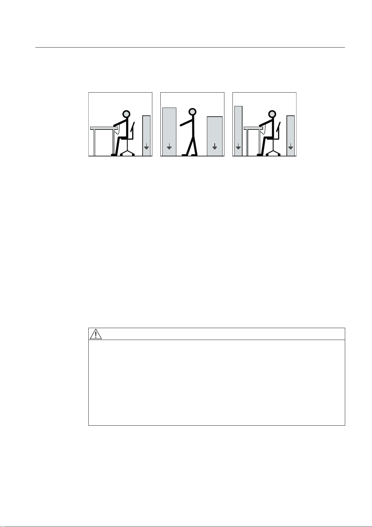
The necessary ESD protective measures for electrostatic sensitive devices are illustrated once
6LW]SODW]
6WHKSODW]
6WHK6LW]SODW]
EE
D
F
D
IIIII
D
FF
H
GG
H
G
again in the following drawings:
a = conductive floor surfaceb = ESD table c = ESD shoes
d = ESD overall e = ESD wristband f = cabinet ground connection
2.6 Interference immunity
By selecting suitable signal cables and evaluation units, companies operating complete plants
and systems must ensure that the interference immunity of the machine is not diminished.
Safety information
2.6 Interference immunity
2.7 Influence on the line power supply through a strongly irregular torque
A strongly irregular torque, for example with the drive of a reciprocating motor, forces a nonsinusoidal motor current. The emerging harmonics can have an impermissible influence on
the line power supply via the connection lines.
2.8 Interference voltages when operating the converter
WARNING
Interference voltages when operating the converter
When a converter is in operation, the emitted interference varies in strength depending on
the converter (manufacturer, type, interference suppression measures undertaken). On
machines with integrated sensors (e.g. PTC thermistors), interference voltages caused by
the converter may occur on the sensor lead. This can cause faults which can result in eventual
or immediate death, serious injury or material damage.
● Comply with the EMC information provided by the manufacturer of the converter. This is
how you prevent the limit values stipulated by IEC/EN 61000-6-3 for the drive system
(consisting of the machine and converter) from being exceeded.
● You must put appropriate EMC measures in place.
SIMOTICS TN Series N-compact 1LH8
Operating Instructions 06/2017 17

Safety information
2.9 Electromagnetic fields when operating electrical power engineering installations
2.9 Electromagnetic fields when operating electrical power engineering
installations
WARNING
Interference to electronic devices caused by electrical power equipment
Electrical power equipment generate electric fields during operation. Potentially lethal
malfunctions can occur in medical implants, e.g. pacemakers, in the vicinity of electrical power
equipment. Data may be lost on magnetic or electronic data carriers.
● It is forbidden for people with pacemakers to enter the vicinity of the machine.
● Protect the personnel working in the plant by taking appropriate measures, such as
erecting identifying markings, safety barriers and warning signs and giving safety talks.
● Observe the nationally applicable health and safety regulations.
● Do not carry any magnetic or electronic data media.
SIMOTICS TN Series N-compact 1LH8
18 Operating Instructions 06/2017
Description
Applications
3
This electrical machine has been designed for a wide range of drive and energy conversion
applications. The machines are characterized by extreme ruggedness, long service life, and
overall reliability. They are also highly versatile, allowing them to be tailored to specific
functions.
Details of the supplied machine and permissible operating conditions can be found in this
documentation.
The machine was designed in accordance with the ordering party's specification and may only
be used for the contractually agreed purpose. The permissible operating conditions are
specified on the rating plate. The technical data are described in the catalog.
WARNING
Risk of explosion
This machine is not designed for use in hazardous areas. An explosion can occur if the
machine is operated in these areas. This can result in death, serious injury or material damage.
● Never operate this machine in hazardous areas.
Machine design
The regulations and standards used as the basis to design and test this machine are stamped
on the rating plate.
The machine design basically complies with the subsequent standards. Please refer to the EU
Declaration of Conformity for the versions of the harmonized standards referenced.
Table 3-1 Machine design
Feature Standard
Rating and performance IEC/EN 60034‑1
Degree of protection IEC/EN 60034‑5
Cooling IEC/EN 60034‑6
Type of construction IEC/EN 60034‑7
Terminal markings and direction of rotation IEC/EN 60034‑8
Noise emission IEC/EN 60034‑9
Starting characteristics, rotating electrical machines IEC/EN 60034‑12*
Vibration severity grades IEC/EN 60034‑14
Vibration limits DIN ISO 10816-3
* For machines in line operation only
SIMOTICS TN Series N-compact 1LH8
Operating Instructions 06/2017 19
10$; 0,1
5RWRU648&$*(./(1,(&
*HZ:WW
1R16,0%7K&O)
,3
9
+]
$
N:
Description
3.1 Comparison of IEC and GOST (D47) standards
See also
Quality documents (Page 133)
3.1 Comparison of IEC and GOST (D47) standards
Comparison of IEC and GOST standards
The IEC/EN standards correspond to the following GOST standards.
IEC/EN GOST
IEC/EN 60034-1 GOST R IEC 60034-1
IEC/EN 60034-5 GOST R IEC 60034-5
IEC/EN 60034-6 GOST R IEC 60034-6
IEC/EN 60034-7 GOST R IEC 60034-7
IEC/EN 60034-8 GOST R IEC 60034-8
IEC/EN 60034-9 GOST R IEC 60034-9
IEC/EN 60034-12 GOST R IEC 60034-12
IEC/EN 60034-14 GOST R IEC 60034-14
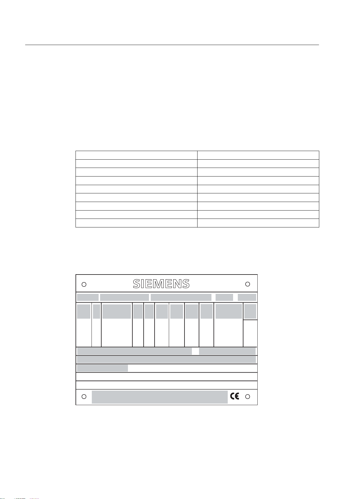
Rating plate
The rating plate shows the identification data and the most important technical data. The data
on the rating plate and the contractual agreements define the limits of proper usage.
Figure 3-1 Schematic diagram of rating plate
20 Operating Instructions 06/2017
SIMOTICS TN Series N-compact 1LH8

Table 3-2 Data on the rating plate
Item Description Item Description
(1) Type of motor (12) Rated speed [rpm]
(2) Motor type (13) Starting current ratio
(3) Serial number (14) (empty)
(4) Type of construction (15) Certificate number
(5) Temperature class (16) Degree of protection
(6) Rated voltage [V] and connections (17) Rotor class
(7) Rated frequency [Hz] (18) Motor weight [kg]
(8) (Content depending on the version) (19) Additional information (optional)
(9) Rated current [A] (20) Maximum speed [rpm]
(10) Rated power [kW] (21) Country of manufacture / City
(11) Power factor [cos φ]
Efficiency requirement
According to EU Regulation (EC) No. 640/2009, the IE3 efficiency requirement for low-voltage
motors with a power of 7.5 kW to 375 kW for line operation has been in force since January
01, 2015.
Description
3.1 Comparison of IEC and GOST (D47) standards
Rotors
Cooling
From January 1, 2017, the IE3 efficiency requirement for motors with a power of 0.75 kW to
375 kW applies for line operation.
Efficiency IE2 still applies for motors that are operated from a converter.
Please note the applicable country-specific rules and regulations.
The rotor assembly is pressed onto the shaft together with the cage winding. The drive end of
the shaft usually has a cylindrical shaft end. Dependent on the design, a second shaft end
may be located at the non-drive end.
The cooling system is designed as a closed, internal cooling circuit. The heat lost from the
machine is dissipated partially via heat conduction and partially via the cooling air at the cooling
water flowing through the cooling pipes. A shaft-mounted fan ensures circulation of the cooling
air.
SIMOTICS TN Series N-compact 1LH8
Operating Instructions 06/2017 21

Description
3.1 Comparison of IEC and GOST (D47) standards
Roller-contact bearings
The machines are equipped with different types of rolling-contact bearings depending on the
version and the operating conditions described in the order. The different types are listed on
the lubricant plate of the machine. In converter operation an insulated bearing is usually
installed on the non-drive end. The following roller-contact bearing variants are available:
Table 3-3 Rolling-contact bearing variants
Version Rolling-contact bearing
Horizontal type of construc‐
tion, coupling output
Vertical type of construc‐
tion, coupling operation
● Drive end: Deep-groove ball bearing as a fixed bearing,
● Non-drive end: Deep-groove ball bearing as a floating bearing with
axial compression springs
● Drive end: Pairing of angular-contact ball bearing / deep-groove ball
bearing as a fixed bearing
● Non-drive end: Deep-groove ball bearing as a floating bearing with
axial compression springs
Rolling-contact bearing design for "Increased degree of protection" (option)
Improved sealing of the bearing units to prevent dust and water from getting in can be achieved
by positioning a grease chamber ahead of the actual bearing unit. Although the same grease
is used in both cases for reasons of convenience, a distinction is made here between
"lubricating grease" and "sealing grease" because of their different functions.
Layout
The spent lubricating grease collects in the space between the bearing housing and the outer
bearing cap. The latter also forms the sealing grease chamber with the labyrinth sealing ring
(optional). The second lubricating nipple containing the grease duct for pressing in the sealing
grease is also located in the outer bearing cap. The chamber is sealed off from the space
where the lubricating grease collects by a V-ring or a V-ring and felt ring combination which
prevents the sealing grease in the chamber from penetrating into the lubricating grease
collecting space. During operation, the sealing grease in the chamber slowly runs out via the
labyrinth and seals it, additionally removing dust from inside and around the outside of the
labyrinth ring.
Terminal box
The terminal box is positioned on the side of the machine. It is fixed to the machine and cannot
be exchanged.
Supplementary devices
Depending on the order, various supplementary devices can be installed or mounted. These
include sensors for bearing temperature monitoring or winding monitoring, for example.
SIMOTICS TN Series N-compact 1LH8
22 Operating Instructions 06/2017

Anti-condensation heating (option)
The machine is fitted with anti-condensation heating. The connection data is listed on an
additional plate on the machine.
Leakage-water sensor
The leakage-water sensor is fitted in the machine enclosure and provides additional security
in the event of leakage.
Description
3.1 Comparison of IEC and GOST (D47) standards
SIMOTICS TN Series N-compact 1LH8
Operating Instructions 06/2017 23

Description
3.1 Comparison of IEC and GOST (D47) standards
SIMOTICS TN Series N-compact 1LH8
24 Operating Instructions 06/2017

Preparations for use
Good planning and preparation of machine applications are essential in terms of keeping
installation simple and avoiding errors, ensuring safe operation, and allowing access to the
machine for servicing and corrective maintenance.
This chapter outlines what you need to consider when configuring your plant in relation to this
machine and the preparations you need to make before the machine is delivered.
4.1 Safety-related aspects to consider when configuring the plant
A number of residual risks are associated with the machine. These are described in the chapter
titled "Safety information" (Page 13) and in related sections.
Take appropriate safety precautions (covers, barriers, markings, etc.) to ensure the machine
is operated safely within your plant.
4.2 Observing the operating mode
Observe the machine's operating mode. Use a suitable control system to prevent overspeeds,
thus protecting the machine from damage.
4
4.3 Ensuring cooling
Ensure that the machine is sufficiently cooled by the cooling air flow at the installation site:
● Ensure that the cooling air can flow in and out unobstructed. The full air flow provided by
the fan is only possible if air can freely enter the impeller. In the axial direction, ensure a
clearance of at least 1 x air intake diameter.
● Make sure that the machine does not draw in the hot discharged air again.
● For machines with a vertical type construction with an air intake from above, ensure that
the air inlets are protected against the ingress of foreign bodies and water.
4.4 Cooling water quality
● The cooling water must circulate in a closed cooling circuit.
● Avoid fluctuations in the oxygen content of the cooling water.
SIMOTICS TN Series N-compact 1LH8
Operating Instructions 06/2017 25

Preparations for use
4.5 Thermal motor protection
Table 4-1 Cooling water specification
Water analysis Measured values
pH > 7.5 - 10
Conductivity < 600 µS/cm
Chloride (Cl-) < 150 mg/l
Manganese (Mn
Fluoride (F) < 0.05 mg/l
Sulfate (SO
Copper (CU2+) < 0.1 mg/l
Silicic acid < 25 mg/l
Free carbon dioxide Without
Total salts < 1000 mg/l
Nitrate level < 20 mg/l
Suspended matter < 10 mg/l
Permanganate consumption < 12 mg/l
Total hardness on German water hardness scale < 12
Carbonate hardness on German water hardness
scale
Ammonium content < 10 mg/l
Iron content < 0.2 mg/l
2-)
2-
) < 150 mg/l
4
< 0.05 mg/l
< 12
Note
Order-specific agreements
Observe any order-specific agreements regarding the cooling water specification. These might
deviate from the named cooling-water specification.
Note
Maintenance
The cooling system is maintenance-free provided cooling water of the specified quality is used.
4.5 Thermal motor protection
The machine is equipped with PTC thermistors for direct monitoring of the motor temperature
to protect the machine against overheating during operation. Plan a corresponding circuit for
monitoring.
See also
Set values for monitoring the winding temperature (Page 77)
Setpoint values for monitoring the bearing temperature (Page 77)
SIMOTICS TN Series N-compact 1LH8
26 Operating Instructions 06/2017

4.6 Interlock circuit for anti-condensation heating (option)
4.6 Interlock circuit for anti-condensation heating (option)
If the anti-condensation heating is operated while the machine is running, this can increase
the temperatures inside the machine.
● Install an interlock circuit that switches off the anti-condensation heating once the main
machine is switched on.
● Only switch on the anti-condensation heating after the machine has been switched off.
See also
Switching off the anti-condensation heating (Page 82)
4.7 Support base for IM B5 construction type
● For machines, type of construction IM B5, provide an additional support foot at the NDE.
The support foot is not included in the scope of supply.
● Use an appropriately sized support foot with the appropriate rigidity. The support foot must
be able to support the total weight of the machine.
The weight of the machine is stated on the rating plate, data on geometry is shown in the
dimension drawing.
Preparations for use
● There is a threaded hole M36 at the bottom of the machine where you can attach the support
foot.
WARNING
Missing support at the NDE
If the machine has no support at the NDE, the flange cannot hold the weight of the machine.
The machine or machine parts may loosen.
This can result in death, serious injury or material damage.
● Use an appropriately sized support base.
4.8 Noise emissions
WARNING
Noise emissions
During operation, the machine's noise emission levels can exceed those permitted at the
workplace, which can cause hearing damage.
Take steps to reduce noise, such as introducing covers and protective insulation or adopting
hearing protection measures, so that the machine can be operated safely within your system.
SIMOTICS TN Series N-compact 1LH8
Operating Instructions 06/2017 27

Preparations for use
4.9 Rotational speed limit values
4.9 Rotational speed limit values
WARNING
Excessively high speeds
Excessive rotational speed can lead to serious damage to the machine. This can result in
death, serious injury, or material damage.
● Avoid operation above the permissible speed by using the appropriate control function.
● Observe the speeds stamped on the rating plate.
4.10 Phase synchronization during supply system switching
NOTICE
Supply system switching
Damage to the machine may be caused when switching to another supply system with
different phasing.
● The phasing must be synchronized during switching. Use appropriate means to
synchronize the phasing.
4.11 Voltage and frequency fluctuations during line operation
If nothing else is stamped on the nameplate, then the permissible voltage fluctuation is ±5 %
and the permissible frequency fluctuation is ±2 %, corresponding to range A in
IEC / EN 60034‑1. Permissible fluctuations that go beyond this are specified on the nameplate,
e.g. voltage fluctuation of ±10 % corresponding to range B in IEC / EN 60034‑1.
The following applies: Under practical operating conditions a machine may sometimes have
to be operated outside the limits of Range A. Exceptions of this sort should be limited with
regard to the values that arise, how often and for how long they occur. Where possible and
within a reasonable time take corrective actions such as reducing the power. Such actions can
avoid thermal ageing leading to a reduction in the service life of the machine.
NOTICE
Overheating of the winding
Exceeding the permissible tolerances for voltage and frequency can lead to an impermissibly
high temperature rise in the windings and thus cause long-term damage to the machine.
SIMOTICS TN Series N-compact 1LH8
28 Operating Instructions 06/2017

Preparations for use
4.12 System-inherent frequencies
4.12 System-inherent frequencies
NOTICE
System resonances
Excessive vibrations and system resonances can damage the machine set.
● Configure and match the system consisting of the foundation and machine set in such a
way that no system resonances can arise and result in the permissible vibration levels
being exceeded.
● The vibration limit values according to DIN ISO 10816-3 must not be exceeded.
4.13 Torsional loading of the drive train due to faults in the electrical supply
In the event of faults in the electrical connection during operation, excessive air gap torques
can lead to additional mechanical torsional load on the line shaft.
Note
The system planner is responsible for the entire drive train.
WARNING
Serious damage to the machine
If the configuration does not correctly recognize the mechanical torsional loadings of the shaft
assembly, this can lead to serious damage to the machine. This can result in death, serious
injury or material damage.
When planning the system, consider the configuration data.
Note
More information about this may be found in the catalog.
4.14 Transport and storage
When carrying out any work on the machine, observe the general safety instructions
(Page 13) and the specifications contained in EN 50110‑1 regarding safe operation on
electrical equipment.
SIMOTICS TN Series N-compact 1LH8
Operating Instructions 06/2017 29

Preparations for use
4.14 Transport and storage
4.14.1 Transport markings
The packing differs depending on the transport type and size. If not otherwise contractually
agreed, the packaging corresponds to the packing guidelines for International Standards for
Phytosanitary Measures (ISPM).
Note the symbols which appear on the packing. These have the following meanings:
Top Fragile material Keep dry Keep cool Center of
4.14.2 Checking the delivery
The components are assembled on an individual basis. When you take receipt of the delivery,
please check immediately whether the scope of the delivery matches up with the
accompanying documents. No claims relating to defects/items missing from the delivery will
be accepted if they are submitted at a later date.
● Report any apparent transport damage to the delivery agent immediately.
● Immediately report any apparent defects/missing components to your contact partner.
These Operating Instructions are part of the scope of delivery; keep them in a location where
they can be easily accessed.
4.14.3 Lifting and transportation
To safely lift and transport the machine, the following requirements must be met:
● Personnel operating cranes and fork-lift trucks must be appropriately qualified.
● If the machine is packed, depending on the weight, size and on-site conditions, lift crates
and transport frames using a fork-lift truck or a crane with slings. Use a crane or fork-lift
truck suitable for the load.
gravity
Do not use
hand hook
Attach here
● When lifting the machine, use only approved and undamaged sling guides and spreaders
of sufficient rated capacity. Check the lifting equipment prior to its use. The weight of the
machine is shown on the rating plate.
● When lifting the machine, refer to the information on the lifting plate.
– Comply with the specified spreading angles.
– Do not exceed the maximum lifting acceleration and lifting speed specified on the lifting
plate. Lift the machine without jerking it.
Acceleration a ≤ 0.4 g (≈ 4 m/s2 )
Velocity v ≤ 20 m/min
SIMOTICS TN Series N-compact 1LH8
30 Operating Instructions 06/2017
 Loading...