

Siemens SIMOTICS T-1FW4407-1KM81-1BC0-Z Operating Instructions Manual

www.siemens.com/drives
Operating Instructions
Installation Instructions
Low-voltage motor
SIMOTICS T-1FW4 Heavy Duty
Type 1FW4407-1KM81-1BC0-Z
Edition 11/2018

13.11.2018 16:04
V5.00

Low-voltage motor
SIMOTICS T-1FW4 Heavy Duty
Type 1FW4407-1KM81-1BC0-Z
Introduction
1
Operating Instructions
Installation Instructions
Safety information
Description
Preparations for use
Assembly
Electrical connection
Start-up
Operation
2
3
4
5
6
7
8
Maintenance
Spare parts
Disposal
Service and Support
Technical data
Quality documents
9
10
11
A
B
C
Edition 11/2018

Legal information
Warning notice system
This manual contains notices you have to observe in order to ensure your personal safety, as well as to prevent
damage to property. The notices referring to your personal safety are highlighted in the manual by a safety alert
symbol, notices referring only to property damage have no safety alert symbol. These notices shown below are
graded according to the degree of danger.
DANGER
indicates that death or severe personal injury will result if proper precautions are not taken.
WARNING
indicates that death or severe personal injury may result if proper precautions are not taken.
CAUTION
indicates that minor personal injury can result if proper precautions are not taken.
NOTICE
indicates that property damage can result if proper precautions are not taken.
If more than one degree of danger is present, the warning notice representing the highest degree of danger will be
used. A notice warning of injury to persons with a safety alert symbol may also include a warning relating to property
damage.
Qualified Personnel
The product/system described in this documentation may be operated only by personnel qualified for the specific
task in accordance with the relevant documentation, in particular its warning notices and safety instructions. Qualified
personnel are those who, based on their training and experience, are capable of identifying risks and avoiding
potential hazards when working with these products/systems.
Proper use of Siemens products
Note the following:
WARNING
Siemens products may only be used for the applications described in the catalog and in the relevant technical
documentation. If products and components from other manufacturers are used, these must be recommended or
approved by Siemens. Proper transport, storage, installation, assembly, commissioning, operation and
maintenance are required to ensure that the products operate safely and without any problems. The permissible
ambient conditions must be complied with. The information in the relevant documentation must be observed.
Trademarks
All names identified by ® are registered trademarks of Siemens AG. The remaining trademarks in this publication
may be trademarks whose use by third parties for their own purposes could violate the rights of the owner.
Disclaimer of Liability
We have reviewed the contents of this publication to ensure consistency with the hardware and software described.
Since variance cannot be precluded entirely, we cannot guarantee full consistency. However, the information in
this publication is reviewed regularly and any necessary corrections are included in subsequent editions.
Siemens AG
Process Industries and Drives
Postfach 48 48
90026 NÜRNBERG
GERMANY
Document order number: A5E37543838-04
Ⓟ 11/2018 Subject to change
Copyright © Siemens AG 2018.
All rights reserved

Table of contents
1 Introduction.................................................................................................................................................11
1.1 Compiling personal documents..............................................................................................11
2 Safety information.......................................................................................................................................13
2.1 Information for those responsible for the plant or system......................................................13
2.2 The 5 safety rules...................................................................................................................13
2.3 Qualified personnel................................................................................................................14
2.4 Safe handling.........................................................................................................................14
2.5 Working on machines with permanent magnets....................................................................15
2.6 Electrostatic sensitive devices...............................................................................................17
2.7 Interference immunity.............................................................................................................18
2.8 Interference voltages when operating the converter..............................................................18
2.9 Electromagnetic fields when operating electrical power engineering installations.................18
3 Description..................................................................................................................................................21
4 Preparations for use...................................................................................................................................25
4.1 Safety-related aspects to consider when configuring the plant..............................................25
4.2 Observing the operating mode...............................................................................................25
4.3 Cooling water quality..............................................................................................................25
4.4 Cooling water inlet temperature (plug-on shaft).....................................................................26
4.5 Noise emissions.....................................................................................................................26
4.6 Rotational speed limit values.................................................................................................27
4.7 System-inherent frequencies.................................................................................................27
4.8 Torsional loading of the drive train due to faults in the electrical supply................................27
4.9 Transport................................................................................................................................28
4.9.1 Safety instructions for transport.............................................................................................28
4.9.1.1 Transporting the machine set.................................................................................................28
4.9.2 Checking the delivery.............................................................................................................28
4.9.3 Transporting a motor that has already been in operation......................................................29
4.9.4 Lifting and transportation........................................................................................................29
4.10 Storage...................................................................................................................................30
4.10.1 Protecting the cooling-water system......................................................................................33
4.11 Converter operation...............................................................................................................33
4.11.1 Converter input voltage..........................................................................................................33
4.11.2 Reducing bearing currents.....................................................................................................34
4.11.3 Insulated bearings when operating the converter..................................................................35
SIMOTICS T-1FW4 Heavy Duty 1FW4407-1KM81-1BC0-Z
Operating Instructions 11/2018 5

Table of contents
5 Assembly....................................................................................................................................................37
5.1 Safety instructions when mounting........................................................................................37
5.1.1 Safety instructions for installation...........................................................................................37
5.2 Preparations for installation....................................................................................................38
5.2.1 Requirements for installation..................................................................................................38
5.2.2 Insulation resistance and polarization index..........................................................................38
5.2.3 Testing the insulation resistance and polarization index........................................................39
5.2.4 Preparing the mating faces....................................................................................................41
5.3 Lift the machine to where it will be installed, and position it...................................................42
5.3.1 Preconditions for correct alignment and secure attachment .................................................42
5.3.2 Checking the load handling attachments...............................................................................42
5.3.3 Removing anti-corrosion protection.......................................................................................42
5.3.4 Shock load and shaft adaptation............................................................................................43
5.3.5 Mounting the output elements................................................................................................44
5.3.6 Lifting and transporting the machine......................................................................................44
5.3.7 Putting the machine down......................................................................................................46
5.3.8 Drain condensate...................................................................................................................46
5.4 Installing the machine............................................................................................................47
5.4.1 Selecting fixing screws...........................................................................................................47
5.4.2 Preconditions for smooth, vibration-free operation................................................................47
5.4.3 Connection cables..................................................................................................................47
5.4.4 Aligning the machine to the driven machine and attaching it to it (IM B5).............................48
5.4.5 Axial and radial forces............................................................................................................48
5.5 Connecting the cooling water supply.....................................................................................49
5.6 Insulated bearings..................................................................................................................50
6 Electrical connection...................................................................................................................................51
6.1 Safety instructions relating to the electrical connection.........................................................51
6.2 Basic rules..............................................................................................................................51
6.3 Preparation.............................................................................................................................52
6.3.1 Terminal designation..............................................................................................................52
6.3.2 Selecting cables.....................................................................................................................53
6.3.3 Connecting the grounding conductor.....................................................................................53
6.4 Inserting and routing the cables.............................................................................................55
6.4.1 Circuit diagram.......................................................................................................................55
6.4.2 Terminal box..........................................................................................................................55
6.4.3 Introducing the cables into the terminal box and routing them...............................................56
6.4.4 Connecting cables with cable lugs.........................................................................................56
6.4.5 Use of aluminum conductors..................................................................................................57
6.4.6 Using single-stranded cables.................................................................................................58
6.4.7 Minimum air clearances.........................................................................................................58
6.4.8 Internal equipotential bonding................................................................................................58
6.4.9 Finishing connection work......................................................................................................59
6.5 Connecting the auxiliary circuits.............................................................................................59
6.5.1 Selecting cables.....................................................................................................................59
6.5.2 Introducing cables into the auxiliary terminal box and routing them......................................60
6.5.3 Connecting the temperature sensor.......................................................................................60
SIMOTICS T-1FW4 Heavy Duty 1FW4407-1KM81-1BC0-Z
6 Operating Instructions 11/2018

Table of contents
6.5.4 Internal equipotential bonding in the auxiliary terminal box...................................................61
6.5.5 Terminating the connection work (auxiliary circuit)................................................................62
6.6 Converter operation...............................................................................................................62
6.6.1 Connection to a converter......................................................................................................62
6.6.2 Operation on a converter with a low pulse frequency............................................................63
6.6.3 Converter operation on a grounded network..........................................................................64
7 Start-up.......................................................................................................................................................65
7.1 Safety instructions for commissioning....................................................................................65
7.2 Checks to be carried out prior to commissioning ..................................................................66
7.3 Greasing the roller bearings prior to commissioning..............................................................67
7.4 Setting the converter pulse frequency....................................................................................68
7.5 Preparing for test run.............................................................................................................69
7.6 Test run..................................................................................................................................69
7.7 Measure the insulation resistance and polarization index for the commissioning..................70
7.8 Switching on the machine......................................................................................................71
7.9 Set values for temperature monitoring of the bearing thermometer.......................................71
7.10 Set values for temperature monitoring (slot thermometer).....................................................72
7.11 Switching off the machine......................................................................................................72
8 Operation....................................................................................................................................................73
8.1 Safety instructions for operation.............................................................................................73
8.2 Switching on the machine......................................................................................................75
8.3 Stoppages..............................................................................................................................76
8.3.1 Prolonged outage periods......................................................................................................76
8.3.2 Avoidance of frost and corrosion damage in the cooling system...........................................76
8.3.3 Avoidance of damage to roller bearings during stoppages....................................................77
8.3.4 Measuring the insulation resistance after an extended non-operational period.....................77
8.4 Switching off the machine......................................................................................................77
8.5 Switching on again after an emergency switching-off............................................................78
8.6 Decommissioning the machine..............................................................................................78
8.7 Re-commissioning the machine.............................................................................................78
8.8 Faults.....................................................................................................................................78
8.8.1 Inspections in the event of faults............................................................................................78
8.8.2 Electrical faults water-cooled machines.................................................................................79
8.8.3 Mechanical faults...................................................................................................................79
8.8.4 Rolling-contact bearing faults.................................................................................................80
8.8.5 Water cooling faults................................................................................................................81
9 Maintenance...............................................................................................................................................83
9.1 Inspection and maintenance..................................................................................................83
9.1.1 Safety instructions for inspection and maintenance...............................................................83
9.1.2 Inspections in the event of faults............................................................................................84
SIMOTICS T-1FW4 Heavy Duty 1FW4407-1KM81-1BC0-Z
Operating Instructions 11/2018 7

Table of contents
9.1.3 First service after installation or repair ..................................................................................85
9.1.4 General inspection.................................................................................................................86
9.1.5 Measuring the insulation resistance during the course of maintenance work........................86
9.1.6 Roller bearing.........................................................................................................................87
9.1.7 Regreasing intervals and types of grease for operating rolling bearings...............................87
9.1.8 Touch up any damaged paintwork.........................................................................................88
9.1.9 Maintaining terminal boxes....................................................................................................89
9.2 Corrective Maintenance.........................................................................................................89
9.2.1 Prepare servicing work...........................................................................................................90
9.2.2 Changing the bearings...........................................................................................................90
9.2.3 Replacing the speed encoder................................................................................................91
9.2.4 Connecting the speed encoder..............................................................................................92
10 Spare parts.................................................................................................................................................95
10.1 Ordering data.........................................................................................................................95
10.2 Ordering spare parts via the Internet.....................................................................................95
11 Disposal......................................................................................................................................................97
11.1 Introduction............................................................................................................................97
11.2 RoHS - restricting the use of certain hazardous substances.................................................97
11.3 Information according to Article 33 of the REACH regulation................................................97
11.4 Preparing for disassembly......................................................................................................98
11.5 Working on machines with permanent magnets....................................................................98
11.6 Disposing of permanent magnets..........................................................................................99
11.7 Disposal of components.......................................................................................................100
A Service and Support.................................................................................................................................103
B Technical data..........................................................................................................................................105
B.1 Tightening torques for screw and bolt connections..............................................................105
C Quality documents....................................................................................................................................107
Index.........................................................................................................................................................109
Tables
Table 3-1 Machine design ........................................................................................................................21
Table 4-1 Cooling water specification .......................................................................................................25
Table 5-1 Stator winding insulation resistance at 40° C..............................................................................40
Table 6-1 Terminal designations using the 1U1-1 as an example..............................................................52
Table 6-2 Determining the cross-section of the grounding conductor.........................................................53
Table 6-3 Tightening torques of bolts (cable lug)........................................................................................54
Table 6-4 Bolt tightening torques (ground terminals) ...............................................................................54
Table 6-5 Data for electrical connection......................................................................................................55
Table 6-6 Minimum air clearance dependent on rms value of the alternating voltage U
.........................58
rms
SIMOTICS T-1FW4 Heavy Duty 1FW4407-1KM81-1BC0-Z
8 Operating Instructions 11/2018

Table of contents
Table 7-1 Guidelines for setting the tripping temperature of bearing thermometers...................................71
Table 7-2 Alarm and shutdown temperatures of the temperature monitoring.............................................72
Table 8-1 Electrical faults .........................................................................................................................79
Table 8-2 Mechanical faults ......................................................................................................................79
Table 8-3 Roller bearing faults ...............................................................................................................80
Table 8-4 Cooling system faults .............................................................................................................81
Table B-1 Tightening torques for bolted connections with a tolerance of ±10%........................................105
Figures
Figure 3-1 Rating plate diagram...................................................................................................................22
Figure 4-1 Schematic representation of a single drive.................................................................................35
Figure 6-1 Water drip loop............................................................................................................................52
Figure 6-2 Neutral point connection..............................................................................................................55
Figure 9-1 Schematic diagram: Detailed view of the speed encoder...........................................................91
Figure 9-2 Electrical connection of the speed sensor ..................................................................................93
SIMOTICS T-1FW4 Heavy Duty 1FW4407-1KM81-1BC0-Z
Operating Instructions 11/2018 9

Table of contents
SIMOTICS T-1FW4 Heavy Duty 1FW4407-1KM81-1BC0-Z
10 Operating Instructions 11/2018

Introduction
In the following text, the motor is referred to as "electrical machine" – or abbreviated, just
"machine".
These operating instructions are valid for water-cooled synchronous motors in the 1FW4 series
with plug-on shaft and a shaft height of 400. The serial number of the motor can be found on
the rating plate.
These instructions describe the machine and explain how to handle it, from initial delivery to
final disposal of the equipment. Keep these instructions for later use.
Read these operating instructions before you handle the machine and follow the instructions
to become familiar with its design and operating principles and thus ensure safe, problem-free
machine operation and long service life.
Safety instructions and handling-related warning notes are provided in these instructions.
When carrying out any activity at or with the machine, carefully comply with all of these notes
for your own safety, to protect other people and to avoid material damage.
Please contact the Service Center (Page 103) if you have any suggestions on how to improve
this document.
Text format features
1
You can find the following text format features in these instructions:
1. Handling instructions are always formatted as a numbered list. Always perform the steps
in the order given.
● Lists are formatted as bulleted lists.
– Lists on the second level are hyphenated.
Note
The note provides you with additional information about the product itself, handling the product
- and the relevant documentation.
1.1 Compiling personal documents
On the Internet pages in Industry Online Support you have the possibility of compiling personal
documents using the function Documentation (
en/documentation)
Using the "Documentation" function, from Product Support manuals, you can compile your
own "Documentation". However, you can also include other Product Support content such as
FAQs or characteristics in the documentation that you compile.
https://support.industry.siemens.com/My/ww/
SIMOTICS T-1FW4 Heavy Duty 1FW4407-1KM81-1BC0-Z
Operating Instructions 11/2018 11

Introduction
1.1 Compiling personal documents
In the "Documentation" function, you have the option of creating your own compiled documents
in your own structure and managing them. You can delete or shift individual chapters or topics.
Further, using the note function you can import your own content. The compiled
"documentation" can be exported as PDF, for example.
Using the "Documentation" function, you can efficiently compile your own plant or system
documentation. The "Documentation" compiled in a specific language can also be
automatically exported in one of the other available languages.
The full functionality is only available for registered users.
SIMOTICS T-1FW4 Heavy Duty 1FW4407-1KM81-1BC0-Z
12 Operating Instructions 11/2018

Safety information
2.1 Information for those responsible for the plant or system
This electric machine has been designed and built in accordance with the specifications
contained in Directive 2014/35/EU ("Low-Voltage Directive") and is intended for use in
industrial plants. Please observe the country-specific regulations when using the electric
machine outside the European Community. Follow the local and industry-specific safety and
setup regulations.
The persons responsible for the plant must ensure the following:
● Planning and configuration work and all work carried out on and with the machine is only
to be done by qualified personnel.
● The operating instructions must always be available for all work.
● The technical data as well as the specifications relating to the permissible installation,
connection, ambient and operating conditions are taken into account at all times.
● The specific setup and safety regulations as well as regulations on the use of personal
protective equipment are observed.
Note
Use the services and support provided by the local service center (Page 103) for planning,
installation, commissioning and service work.
2
2.2 The 5 safety rules
For your own personal safety and to prevent material damage when carrying out any work,
always observe the safety-relevant instructions and the following five safety rules according
to EN 50110‑1 "Working in a voltage-free state". Apply the five safety rules in the sequence
stated before starting work.
5 safety rules
1. Disconnect the system.
Also disconnect the auxiliary circuits, for example, anti-condensation heating.
2. Secure against reconnection.
3. Verify absence of operating voltage.
4. Ground and short-circuit.
5. Provide protection against adjacent live parts.
To energize the system, apply the measures in reverse order.
SIMOTICS T-1FW4 Heavy Duty 1FW4407-1KM81-1BC0-Z
Operating Instructions 11/2018 13

Safety information
2.3 Qualified personnel
2.3 Qualified personnel
All work at the machine must be carried out by qualified personnel only. For the purpose of
this documentation, qualified personnel is taken to mean people who fulfill the following
requirements:
● Through appropriate training and experience, they are able to recognize and avoid risks
and potential dangers in their particular field of activity.
● They have been instructed to carry out work on the machine by the appropriate person
responsible.
2.4 Safe handling
Workplace safety depends on the attentiveness, care, and common sense of the personnel
who install, operate, and maintain the machine. In addition to the safety measures cited, as a
matter of principle, the use of caution is necessary when you are near the machine. Always
pay attention to your safety.
Also observe the following to prevent accidents:
● General safety regulations applicable in the country where the machine is deployed.
● Manufacturer-specific and application-specific regulations
● Special agreements made with the operator
● Separate safety instructions supplied with the machine
● Safety symbols and instructions on the machine and its packaging
Danger as a result of stationary parts under voltage (live parts)
Live parts represent a hazard. Touch protection against active (live) parts is no longer
guaranteed if covers are removed. The minimum clearance and creepage distances may be
violated when coming close to live parts. Touching or coming close to them can result in death,
serious injury or material damage.
● Ensure that all live parts are suitably covered.
● Switch off and disconnect the machine first if you want to remove covers. Observe the "5
safety rules".
Risk of injury due to rotating parts
Rotating parts are dangerous. Touch protection against rotating parts is no longer guaranteed
if covers are removed. Touching rotating parts can result in death, serious injury or material
damage.
● Ensure that all rotating parts are reliably covered.
● Switch off and disconnect the machine first if you want to remove covers. Observe the "5
safety rules".
● Only remove covers when the rotating parts have come to a complete standstill.
SIMOTICS T-1FW4 Heavy Duty 1FW4407-1KM81-1BC0-Z
14 Operating Instructions 11/2018

Risk of burns due to hot surfaces
Individual machine parts can become hot in operation. Burns can result when coming into
contact with these parts.
● Never touch machine parts during operation.
● Allow the machine to cool before starting work on the machine.
● Check the temperature of parts before touching them. If required, wear suitable protective
equipment.
Health hazard due to chemical substances
Chemical substances required for the setup, operation and maintenance of machines can
present a health risk.
● Observe the product information provided by the manufacturer.
Flammable substances hazard
Chemical substances required for the setup, operation and maintenance of machines may be
flammable. These substances can ignite if handled incorrectly. They can cause burns and
property damage.
Safety information
2.5 Working on machines with permanent magnets
See also
Noise emissions
● Observe the product information provided by the manufacturer.
The 5 safety rules (Page 13)
Inspection and maintenance (Page 83)
During operation, the machine's noise emission levels can exceed those permitted at the
workplace, which can cause hearing damage.
● Ensure that nobody is in the area of increased noise emissions during machine operation.
● Take steps to reduce noise so that the machine can be operated safely within your system.
The following measures may help to reduce noise.
– Covers
– Noise insulation
– Hearing protection measures
2.5 Working on machines with permanent magnets
On machines with permanent magnets, the magnetic field is guided in an assembled state in
the magnetic circuit of the machine. This means that no magnetic fields, which may be to your
health, are detectable outside the machine.
SIMOTICS T-1FW4 Heavy Duty 1FW4407-1KM81-1BC0-Z
Operating Instructions 11/2018 15

Safety information
2.5 Working on machines with permanent magnets
WARNING
Strong magnetic field when the machine is open
A strong magnetic field is always present inside the machine. If the housing is open, e.g.
when maintenance openings are open or when working inside the machine, magnetic objects
can be suddenly attracted by this magnetic field. This can result in death, serious injury or
material damage.
● Working in the vicinity of the rotor is only permitted in exceptional circumstances.
Unambiguous access rules must be established in accordance with the magnetic fields
prevailing in the workplace. Clearly mark the boundaries of the areas where standing is
permitted.
● People who need to use electronic or magnetic medical aids such as pacemakers, hearing
aids, implants or similar devices, are at particularly high risk. Such persons must undergo
an industrial medicine assessment.
● Observe the following measures.
Personal protective measures
● Ensure that you never wear or carry any of the following objects and that they are kept a
safe distance from the machine:
– All kinds of magnetic metal parts such as, keys, glasses, tools, knives, scissors, tape
measures, etc.
– Magnetic jewelry such as rings, chains, needles, watches, etc.
– Electronic devices and data carriers such as service cards, check cards, credit cards,
calculators, cell phones, etc.
– Wallets or other iron-containing objects
– Electrically conductive foreign bodies
● Do not use any magnetic tools or lifting devices.
● Wear only occupational safety items without magnetic metal parts, e.g. occupational safety
shoes with non-magnetic protective caps and soles.
● Keep your shoes and clothing free from chips and waste containing iron.
● Exercise caution when installing accessories. Ensure that no parts fall into the inside of the
machine.
● Do not perform any cutting at the machine, e.g. manufacturing threaded holes. Any
exceptions require written approval from the manufacturer.
SIMOTICS T-1FW4 Heavy Duty 1FW4407-1KM81-1BC0-Z
16 Operating Instructions 11/2018

Danger due to induced voltages
Electrical voltages are induced in the stator when rotating the rotor. Touching the stator
connections can result in death or severe physical injury.
● Before starting any work at the machine, carefully ensure that the system is secured to
prevent the rotor accidentally turning in compliance with the regulations.
● If you must rotate the rotor, then ensure that each phase is grounded.
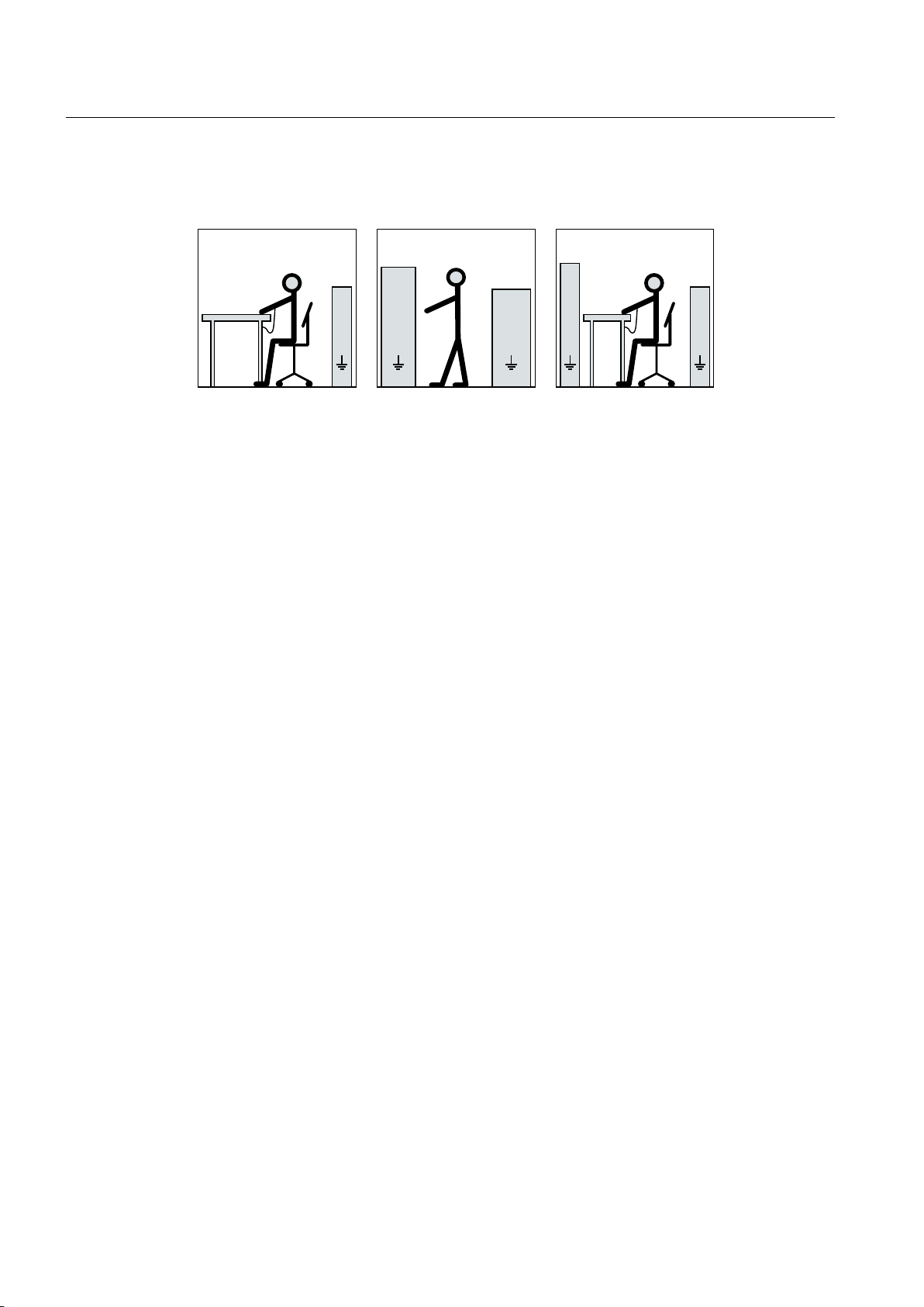
2.6 Electrostatic sensitive devices
Material damage due to electrostatic discharge
Electronic modules contain components that can be destroyed by electrostatic discharge.
These components can be damaged or destroyed if they are not handled correctly. To protect
equipment against damage, follow the instructions given below.
Safety information
2.6 Electrostatic sensitive devices
● Only touch electronic modules if you absolutely have to work on them.
● The body of the person concerned must have been electrostatically discharged and
grounded immediately before any electronic modules are touched.
● Electronic modules should not be brought into contact with electrically insulating materials,
such as:
– Plastic film
– Plastic parts
– Insulating table supports
– Clothing made of synthetic fibers
● Always place electrostatic sensitive devices on conductive bases.
● Always pack, store and transport electronic modules or components in conductive
packaging, such as:
– Metallized plastic or metal containers
– Conductive foam material
– Domestic aluminum foil
SIMOTICS T-1FW4 Heavy Duty 1FW4407-1KM81-1BC0-Z
Operating Instructions 11/2018 17
6HDWLQJSRVLWLRQ
6WDQGLQJSRVLWLRQ
6WDQGLQJVHDWLQJSRVLWLRQ
EE
D
F
D
IIIII
D
FF
H
GG
H
G
Safety information
2.7 Interference immunity
The necessary ESD protective measures for electrostatic sensitive devices are illustrated once
again in the following drawings:
a = conductive floor surfaceb = ESD table c = ESD shoes
d = ESD overall e = ESD wristband f = cabinet ground connection
2.7 Interference immunity
By selecting suitable signal cables and evaluation units, ensure that the interference immunity
of the machine is not diminished.
2.8 Interference voltages when operating the converter
Interference voltages when operating the converter
When a converter is in operation, the emitted interference varies in strength depending on the
converter (manufacturer, type, interference suppression measures undertaken). On machines
with integrated sensors (e.g. PTC thermistors), interference voltages caused by the converter
may occur on the sensor lead. This can cause faults which can result in eventual or immediate
death, serious injury or material damage.
● Comply with the EMC information provided by the manufacturer of the converter. This is
how you prevent the limit values stipulated by IEC/EN 61000-6-3 for the drive system
(consisting of the machine and converter) from being exceeded.
● You must put appropriate EMC measures in place.
2.9 Electromagnetic fields when operating electrical power engineering installations
Electrical power equipment generate electromagnetic fields during operation. Potentially lethal
malfunctions can occur in medical implants, e.g. pacemakers, in the vicinity of electrical power
equipment. Data may be lost on magnetic or electronic data carriers.
● Protect the personnel working in the plant by taking appropriate measures, such as erecting
identifying markings, safety barriers and warning signs and giving safety talks.
● Observe the nationally applicable health and safety regulations.
18 Operating Instructions 11/2018
SIMOTICS T-1FW4 Heavy Duty 1FW4407-1KM81-1BC0-Z

2.9 Electromagnetic fields when operating electrical power engineering installations
● It is forbidden for people with pacemakers to be close to the machine.
● Do not carry any magnetic or electronic data media.
Safety information
SIMOTICS T-1FW4 Heavy Duty 1FW4407-1KM81-1BC0-Z
Operating Instructions 11/2018 19

Safety information
2.9 Electromagnetic fields when operating electrical power engineering installations
SIMOTICS T-1FW4 Heavy Duty 1FW4407-1KM81-1BC0-Z
20 Operating Instructions 11/2018
Description
Area of application
The series 1FW4 motors are multi-pole, permanent-magnet synchronous motors with plug-on
shaft. The motors are available as a water-cooled version. The operating behavior is
comparable to that of electrically excited synchronous motors.
Motors of the 1FW4 series are used together with converters as slow running direct drives.
Risk of explosion
This machine is not designed for use in hazardous areas. An explosion can occur if the
machine is operated in these areas. This can result in death, serious injury or material damage.
● Never operate this machine in hazardous areas.
Machine design
3
WARNING
See also
The regulations and standards used as basis for designing and testing this machine are
stamped on the rating plate. The machine design basically complies with the subsequent
standards: Please refer to the EU Declaration of Conformity for the versions of the harmonized
standards referenced.
Table 3-1 Machine design
Feature Standard
Dimensions and operation characteristics IEC / EN 60034-1
Degree of protection IEC / EN 60034-5
Cooling IEC / EN 60034-6
Type of construction IEC / EN 60034-7
Terminal markings and direction of rotation IEC/EN 60034-8
Noise emission IEC / EN 60034-9
Mechanical vibrations IEC / EN 60034-14
IEC‑standard voltages IEC/DIN IEC 60038
Vibration limit values DIN ISO 10816-3
Quality documents (Page 107)
SIMOTICS T-1FW4 Heavy Duty 1FW4407-1KM81-1BC0-Z
Operating Instructions 11/2018 21
Description
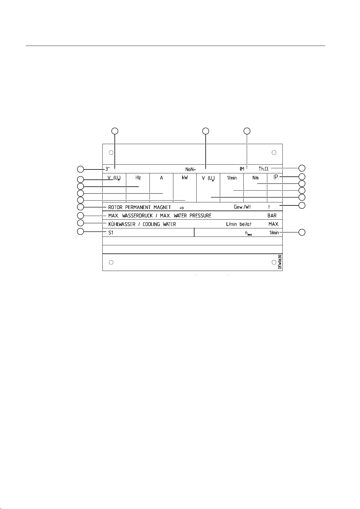
Rating plate
The rating plate shows the identification data and the most important technical data. The data
on the rating plate and the contractual agreements define the limits of proper usage.
Rating plate
① Motor type: Three-phase motor ⑪ Maximum operating speed [rpm]
② Motor type: Synchronous motor, order num‐
ber
⑫ Operating mode
③ Serial number ⑬ Required amount of cooling water [l/min] at
the maximum cooling water inlet tempera‐
ture [°C]
④ Type ⑭ Maximum water pressure [bar]
⑤ Temperature class ⑮ Rotors, standards and regulations
⑥ Degree of protection ⑯ Rated power [kW]
⑦ Rated torque [Nm] ⑰ Rated current [A]
⑧ Rated speed [rpm] ⑱ Rated frequency [Hz]
⑨ Induced voltage ⑲ Rated voltage [V]
⑩ Motor weight [t]
Figure 3-1 Rating plate diagram
Degree of protection
The machine is available with degree of protection IP55.
SIMOTICS T-1FW4 Heavy Duty 1FW4407-1KM81-1BC0-Z
22 Operating Instructions 11/2018

Ambient conditions
Water cooling
See also
Description
The standard machines are not suitable for use in corrosive atmospheres, atmospheres with
a high salt content, or outdoor applications.
The cooling system is designed as a closed, internal cooling circuit. The cooling water pipe
system is integrated into the stator core and designed in stainless steel. The machine has
cooling type IC71W according to IEC / EN 60034‑6.
Cooling capacity
To ensure adequate cooling of the machine, it is essential to adhere to the specified cooling
water rate, temperature and cooling water quality.
Cooling water quality (Page 25)
Drive
The machine is designed for operation with SINAMICS converters and has been type-tested
for use with these converters. No liability is assumed in respect of damage to the motor or
converter and no warranty is issued in respect of the drive function if you operate the motor
with a different converter.
As far as the SINAMICS Motor Modules are concerned, special control software has been
developed for these motors. The converter module is selected depending on many influencing
parameters, e.g.:
● Torque
● Speed
● Overload
● Duty cycles
● Control precision
● Capable of energy recovery
Supplementary devices
Temperature sensors are integrated in the stator winding to monitor the winding temperature.
Various supplementary devices can be integrated or mounted, depending on the order. These
include, for example, anti-condensation heating to prevent condensation or temperature
sensors for monitoring bearings.
SIMOTICS T-1FW4 Heavy Duty 1FW4407-1KM81-1BC0-Z
Operating Instructions 11/2018 23

Description
SIMOTICS T-1FW4 Heavy Duty 1FW4407-1KM81-1BC0-Z
24 Operating Instructions 11/2018

Preparations for use
Good planning and preparation of machine applications are essential in terms of keeping
installation simple and avoiding errors, ensuring safe operation, and allowing access to the
machine for servicing and corrective maintenance.
This chapter outlines what you need to consider when configuring your plant in relation to this
machine and the preparations you need to make before the machine is delivered.
4.1 Safety-related aspects to consider when configuring the plant
A number of residual risks are associated with the machine. These are described in the chapter
titled "Safety information" (Page 13) and in related sections.
Take appropriate safety precautions (covers, barriers, markings, etc.) to ensure the machine
is operated safely within your plant.
4.2 Observing the operating mode
Observe the machine's operating mode. Use a suitable control system to prevent overspeeds,
thus protecting the machine from damage.
4
4.3 Cooling water quality
The values specified for the cooling water correspond to the requirements for a closed cooling
circuit. Not all of the specified concentrations will occur in the cooling water at the same time.
You can use a filter to ensure disturbance-free operation. The filter mesh size should not be
less than 100 μm.
Observe any order-specific agreements regarding the cooling water specification. These might
deviate from the cooling water specification given above.
The cooling system is maintenance-free provided cooling water of the specified quality is used.
Cooling water specification
Table 4-1 Cooling water specification
Constituent Value
pH value 6.0 … 9.0
Total hardness < 170 ppm
Conductivity < 500 μS/cm
Chloride ions < 40 ppm
SIMOTICS T-1FW4 Heavy Duty 1FW4407-1KM81-1BC0-Z
Operating Instructions 11/2018 25

Preparations for use
4.4 Cooling water inlet temperature (plug-on shaft)
Constituent Value
Sulfate ions < 50 ppm
Nitrate ions < 50 ppm
Dissolved solids < 340 ppm
Max. grain size < 100 μm
Operating pressure 6 bar max.
Inlet temperature < 25 °C
Minimum cooling water inlet temperature T
Anti-freeze protection / corrosion protection 20 … 30 %
NALCO 00GE056 inhibitor 0.2 … 0.25 %
cooling water
> T
ambient
4.4 Cooling water inlet temperature (plug-on shaft)
Cooling water intake temperature
The maximum cooling water intake temperature is 25 °C.
- 5 K
NOTICE
Condensation for an excessively low cooling water intake temperature
If the temperature difference between cooling water and ambient temperature is greater than
5 K, this may result in condensation forming in the machine. This results in material damage.
● Make sure that the condensation can drain away freely.
● Adopt appropriate measures to achieve the required intake temperature of the cooling
water.
● Alternatively, dry the ambient air.
4.5 Noise emissions
Noise emissions
During operation, the machine's noise emission levels can exceed those permitted at the
workplace, which can cause hearing damage.
● Ensure that nobody is in the area of increased noise emissions during machine operation.
● Take steps to reduce noise so that the machine can be operated safely within your system.
The following measures may help to reduce noise.
– Covers
– Noise insulation
– Hearing protection measures
SIMOTICS T-1FW4 Heavy Duty 1FW4407-1KM81-1BC0-Z
26 Operating Instructions 11/2018

4.6 Rotational speed limit values
Excessive rotational speed can lead to serious damage to the machine and the converter. This
can result in death, serious injury or material damage.
● The converter control must ensure that operation at impermissible speeds is prevented.
● Please note the speed data specified in the Electrical Data.
4.7 System-inherent frequencies
Excessively high vibration levels and system resonances can damage the machine set.
● Configure and match the system consisting of the foundation and machine set in such a
way that no system resonances can arise and result in the permissible vibration levels being
exceeded.
● The vibration values according to DIN ISO 10816-3 must not be exceeded.
Preparations for use
4.6 Rotational speed limit values
4.8 Torsional loading of the drive train due to faults in the electrical supply
In the event of faults in the electrical connection during operation, excessive air gap torques
can lead to additional mechanical torsional load on the line shaft.
Risk of torsional stress on the drive train
If the configuration does not correctly recognize the mechanical torsional loadings of the shaft
assembly, this can lead to serious damage to the machine. This can result in death, serious
injury or material damage.
● When planning the system, consider the configuration data. The system planner is
responsible for the entire drive train.
Note
More information about this may be found in the catalog.
SIMOTICS T-1FW4 Heavy Duty 1FW4407-1KM81-1BC0-Z
Operating Instructions 11/2018 27

Preparations for use
4.9 Transport
4.9 Transport
4.9.1 Safety instructions for transport
Observe the following when carrying out any work on the machine:
● Comply with the general safety instructions (Page 13)
● Comply with the applicable national and sector-specific regulations.
● When using the machine within the European Union, comply with the specifications laid
down in EN 50110‑1 regarding safe operation of electrical equipment.
Danger due to induced voltages
Electrical voltages are induced in the stator when rotating the rotor. Touching the stator
connections can result in death or severe physical injury.
● Before starting any work at the machine, carefully ensure that the system is secured to
prevent the rotor accidentally turning in compliance with the regulations.
● If you must rotate the rotor, then ensure that each phase is grounded.
4.9.1.1 Transporting the machine set
Danger if the machine falls
The attachment points on the machine are designed for the weight of the machine only. If a
machine set is lifted and transported at a single machine, this can fracture the attachment
point. The machine or machine set may fall. This can result in death, serious injury or material
damage.
● Do not lift machine sets by attaching lifting tackle to the individual machines.
● Use only the equipment provided, e.g. the openings or lugs on the base plates, for
transporting machine sets. Note the maximum capacity of the lifting lug.
4.9.2 Checking the delivery
The components are assembled on an individual basis. When you take receipt of the delivery,
please check immediately whether the scope of the delivery matches up with the
accompanying documents. Subsequent claims cannot be recognized.
● Report any apparent transport damage to the delivery agent immediately.
● Immediately report any apparent defects/missing components to your contact partner.
These Operating Instructions are part of the scope of delivery; keep them in a location where
they can be easily accessed.
SIMOTICS T-1FW4 Heavy Duty 1FW4407-1KM81-1BC0-Z
28 Operating Instructions 11/2018

4.9.3 Transporting a motor that has already been in operation
If you have already operated the motor and now want to transport it, proceed as follows:
1. Allow the motor to cool down.
2. Remove the connections provided by the customer.
3. Drain the cooling-water system and purge it carefully with air.
4. Fit the rotor shipping brace, if present.
5. Only use the eyebolts on the bearing shields - for example - to transport and lift the motor.
4.9.4 Lifting and transportation
To safely lift and transport the machine, the following requirements must be met:
● Personnel operating cranes and fork-lift trucks must be appropriately qualified.
● If the machine is packed, depending on the weight, size and on-site conditions, lift crates
and transport frames using a fork-lift truck or a crane with slings. Use a crane or fork-lift
truck suitable for the load.
Preparations for use
4.9 Transport
● When lifting the machine, use only approved and undamaged sling guides and spreaders
of sufficient rated capacity. Check the lifting equipment prior to its use. The weight of the
machine is shown on the rating plate.
● When lifting the machine, refer to the information on the lifting plate.
– Comply with the specified spreading angles.
– Do not exceed the maximum lifting acceleration and lifting speed specified on the lifting
plate. Lift the machine without jerking it.
Acceleration a ≤ 0.4 g (≈ 4 m/s2 )
Velocity v ≤ 20 m/min
WARNING
Transport for a different type of construction
If you do not transport or lift the machine in a position appropriate for its construction, the
machine can tip, slip into the lifting equipment or fall down. This can result in death, serious
injury or material damage.
● Use only the load carrying device on the stator frame for lifting.
● Use the load carrying device appropriate for the machine position.
● Only use suitable rope guiding or spreading devices.
SIMOTICS T-1FW4 Heavy Duty 1FW4407-1KM81-1BC0-Z
Operating Instructions 11/2018 29

Preparations for use
4.10 Storage
● Never remain under or in the immediate vicinity of the machine when it is lifted.
WARNING
Center of gravity not centered
If the center of gravity of a load is not located centrally between the attachment points, the
machine can tip over or slip out of the lifting equipment and fall when it is being transported
or lifted. This can result in death, serious injury or material damage.
● Comply with the handling instructions on the machine when transporting it.
● Be aware of the possibility of different loads on the sling ropes or lifting straps and the
carrying capacity of the lifting equipment.
● Always take account of the center of gravity when transporting or lifting the machine. If
the center of gravity is not located centrally between the attachment points, then position
the hoisting hook above the center of gravity.
WARNING
Danger to life as a result of a machine falling
If the lifting gear or load handling attachments were to fail, the machine could fall. This
can result in death, serious injury or material damage.
● In order to gain easy and safe access to the underside of the machine, place it in a
secure and raised position.
4.10 Storage
You must correctly store the machine if you do not install and use it after it has been delivered.
NOTICE
Bearing seizure damage if incorrectly stored
If storage conditions are inappropriate there is a risk of bearing seizure damage. Resulting
damage can include scoring (brinelling) and corrosion.
● Follow the storage guidelines.
Preconditions and preparations
● Only store goods in undamaged packaging. Unpack the goods if the packaging is damaged.
Correctly store the goods corresponding to the type.
● Repair any damage to the packaging before putting the equipment into storage insofar as
this is necessary to ensure proper storage conditions.
SIMOTICS T-1FW4 Heavy Duty 1FW4407-1KM81-1BC0-Z
30 Operating Instructions 11/2018
 Loading...