

Siemens Simotics SD 1LE7 Operating Instructions Manual


Low-voltage motors
SIMOTICS SD
1LE7
Compact Operating Instructions
1
Introduction
2
Safety notes
2.1
Information for those responsible for the plant or system
Note
Use the services and suppo
commissioning and service work.
2.2
The 5 safety rules
5 safety rules
These instructions describe the machine and explain how to handle it, from initial delivery to final disposal of the equipment.
Keep these instructions for later use.
Read these operating instructions before you handle the machine and follow the instructions to become familiar with its
design and operating principles and thus ensure safe, problem-free machine operation and long service life.
Please contact the service center if you have any suggestions on how to improve this document.
This electric machine has been designed and built in accordance with the specifications contained in Directive IS 12615, and
is intended for use in industrial plants and systems. Please observe the country-specific regulations when using the electric
machine outside India. Follow the local and industry-specific safety and setup regulations.
The persons responsible for the plant must ensure the following:
● Planning and configuration work and all work carried out on and with the machine is only to be done by qualified
personnel.
● The operating instructions must always be available for all work.
● The technical data as well as the specifications relating to the permissible installation, connection, ambient and operating
conditions are taken into account at all times.
● The specific setup and safety regulations as well as regulations on the use of personal protective equipment are
observed.
You will find safety instructions in the individual sections of this document. Follow the safety instructions for your own safety,
to protect other people and to avoid damage to property.
Observe the following safety instructions for all activities on and with the machine.
For your own personal safety and to prevent material damage when carrying out any work, always observe the safetyrelevant instructions and the following five safety rules according to EN 50110-1 "Working in a voltage-free state". Apply the
five safety rules in the sequence stated before starting work.
rt provided by the appropriate service center (Page 38) for planning, installation,
1. Disconnect the system.
Also disconnect the auxiliary circuits, for example, anti-condensation heating.
2. Secure against reconnection.
3. Verify absence of operating voltage.
© Siemens AG 2016 - 2018. All rights reserved
A5E36065207, 04/2018
1
2.3
Qualified personnel
2.4
Safe handling
WARNING
Live parts
"Maintenance" (Page 27) chapter of the operating instructions.
WARNING
Rotating parts
• Secure free shaft extensions and other rotating part such as couplings and pulley belts so that they cannot be touched.
WARNING
Hot surfaces
• Operate the machine properly.
4. Ground and short-circuit.
5. Provide protection against adjacent live parts.
To energize the system, apply the measures in reverse order.
All work at the machine must be carried out by qualified personnel only. For the purpose of this documentation, qualified
personnel is taken to mean people who fulfill the following requirements:
● Through appropriate training and experience, they are able to recognize and avoid risks and potential dangers in their
particular field of activity.
● They have been instructed to carry out work on the machine by the appropriate person responsible.
Workplace safety depends on the attentiveness, care, and common sense of the personnel who install, operate, and
maintain the machine. In addition to the safety measures cited, as a matter of principle, the use of caution is necessary when
you are near the machine. Always pay attention to your safety.
Also observe the following to prevent accidents:
● General safety regulations applicable in the country where the machine is deployed.
● Manufacturer-specific and application-specific regulations
● Special agreements made with the operator
● Separate safety instructions supplied with the machine
● Safety symbols and instructions on the machine and its packaging
Electric machines contain live parts.
Fatal or severe injuries and substantial material damage can occur if the covers are removed or if the machine
is not handled, operated, or maintained properly.
• Always observe the “five safety rules" (Page 1) when carrying out any work on the machine.
• Only remove covers in the manner described in the operating instructions.
• Operate the machine properly.
• Regularly and professionally maintain the machine according to the instructions provided in the
Electric machines contain dangerous rotating parts.
Fatal or severe injuries and substantial material damage can occur if the covers are removed or if the machine is not
handled, operated, or maintained properly.
• Only remove the covers using the methods described by these operating instructions.
• Operate the machine properly.
• Regularly and correctly maintain the machine.
Electric machines have hot surfaces. Touching hot surfaces can result in severe burns.
• Allow the machine to cool before starting work on the machine.
• Only remove the covers using the methods described by these operating instructions.
1LE7
2 A5E36065207, 04/2018

CAUTION
Hazardous substances
• Observe the relevant safety regulations and wear the personal protective equipment specified.
CAUTION
Flammable substances
• Observe the relevant safety regulations and wear the personal protective equipment specified.
Interference to electronic devices caused by electrical power equipment
3
Description
3.1
Applications
3.1.1
Intended use
Intended use of the machines
Note
Machine directive
Low
Directive. Commissioning is prohibited until it has been absolutely identified that the end product is in conformance with th
Directive. Plea
WARNING
Risk of explosion
Never operate this machine in hazardous areas.
Chemical substances required for the setup, operation and maintenance of machines can present a health risk.
• Read the information in these operating instructions and the product information supplied by the manufacturer.
Chemical substances required for the setup, operation and maintenance of machines may be flammable.
Burns and other damage to health and material may result.
• Read the information in these operating instructions and the product information supplied by the manufacturer.
Electrical power equipment generate electric fields during operation. Potentially lethal malfunctions can occur in medical
implants, e.g. pacemakers, in the vicinity of electrical power equipment. Data may be lost on magnetic or electronic data
carriers.
● It is forbidden for people with pacemakers to enter the vicinity of the machine.
● Protect the personnel working in the plant by taking appropriate measures, such as erecting identifying markings, safety
barriers and warning signs and giving safety talks.
● Observe the nationally applicable health and safety regulations.
● Do not carry any magnetic or electronic data media.
These machines are intended for industrial installations. They comply with the harmonized standards of the series
EN / IEC 60034-1 (VDE 0530, IS 12615). It is prohibited to use these motors in hazardous zones if the marking on the rating
plate does not explicitly permit line or converter operation. If other/more wide-ranging demands (e.g. protection so that they
cannot be touched by children) are made in special cases – i.e. use in non-industrial installations – these conditions must be
ensured by the customer.
-voltage motors are components designed for installation in machines in accordance with the current Machinery
This machine is not designed for use in hazardous areas. An explosion can occur if the machine is operated in these
areas. This can result in death, serious injury or material damage.
•
is
se observe the EN / IEC 60204-1 standard.
1LE7
A5E36065207, 04/2018
3

3.1.2
CE marking
Use of machines without CE marking
3.2
Design
3.2.1
Machine design
3.2.2
Regulations
Feature
Standard
ing electrical machines and inspections
Degree of protection
EN / IEC 60034-5
Cooling
EN / IEC 60034-6
Type of construction
EN / IEC 60034-7
IS 2253
Dimensions of three phase foot mounted induction motors
Dimensions of three phase flange mounted induction motors
Terminal markings and direction of rotation
EN / IEC 60034-8
Starting characteristics of rotating electrical machines
EN / IEC 60034-12
Vibration severity grades
EN / IEC 60034-14
IS 12075
motors
IEC standard voltages
IEC 60038
Code of practice for earthing
3.2.3
Cooling and ventilation
Forced ventilation (optional): Type of cooling IC 416 in accordance with EN / IEC 60034-6
See also
Machines without CE marking are intended for operation outside the European Economic Area (EEA). Do not use any
machines without a CE marking in the EEA!
Machines of this series are low-voltage three-phase induction or reluctance-synchronous machines with a cylindrical shaft
end and keyway. They can be supplied as single-speed machines with different efficiency classes or as pole changing
machines for several speeds.
In the case of machines with feet (IM B3 type of construction), the feet are cast.
The regulations and standards used as the basis for designing and testing this machine are stamped on the rating plate. The
machine design basically complies with the following standards:
Table 3-1 Applicable general regulations
Dimensioning and operating behavior EN / IEC 60034-1 IS 12615, IS/IEC 60034-1
Procedure for determining the losses and the efficiency of rotat-
Maße von Drehstrom-Asynchronmotoren für Fußmontage
Maße von Drehstrom-Asynchronmotore für Flanschmontage
Efficiency classification of three-phase squirrel-cage induction
Leitfaden für die Erdung
EN / IEC 60034-2-1 IS 12615
IS 1231
IS 2223
EN / IEC 60034-30 -1 IS 12615
IS 3043
Cooling that does not depend on the speed is achieved by means of a unit that is independent of the motor operating state
(forced ventilation). This unit is closed to the outside by a fan cover. It has its own main drive with fan impeller which creates
the cooling air flow required for cooling the motor.
Commissioning an external fan (Page 22)
1LE7
4 A5E36065207, 04/2018
3.2.4
Bearings
3.2.5
Balancing
3.2.6
Types of construction/method of installation
WARNING
Machine parts can fall
Do not use machines in frame sizes ≥ 315L in the IM V3 type of assembly.
See also
Basic type of construction
code
Diagram
Other methods of installation
Diagram
In order to support the machine shaft and maintain its position in the non-moving part of the machine, only 2 rolling bearings
are used. One rolling bearing performs the function of a location bearing that transfers axial and radial forces from the
rotating machine shaft to the non-moving part of the machine. The second rolling bearing is implemented as floating and
support bearing in order to allow thermal expansion inside the machine and transfer radial forces.
The nominal (calculated) useful life of the bearings according to ISO 281 is at least 50 000 hours if the motor is coupled via a
direct flexible coupling. However, the achievable useful life of the bearings can be significantly longer in the case of lower
forces (e.g. operation with self-aligning couplings).
Rolling bearings with permanent lubrication are maintenance-free.
As standard, the motor is balanced dynamically with a half feather key (code "H").
Vibration level "A" is standard and, if ordered as an option, vibration level B is specified on the rating plate.
The type of construction of the machine is stated on the rating plate.
The machine is made up of heavy parts. Incorrect assembly type can result in death, serious injury or material damage.
•
Alignment and mounting (Page 16)
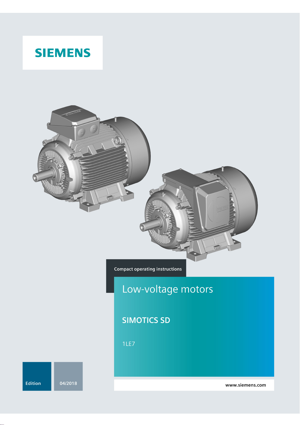
Table 3-2 Type of construction
IM B3 (IM 1001)
IM V6 (IM 1031)
IM B6 (IM 1051)
IM B7 (IM 1061)
IM V5 (IM 1011)
IM B8 (IM 1071)
1LE7
A5E36065207, 04/2018
5
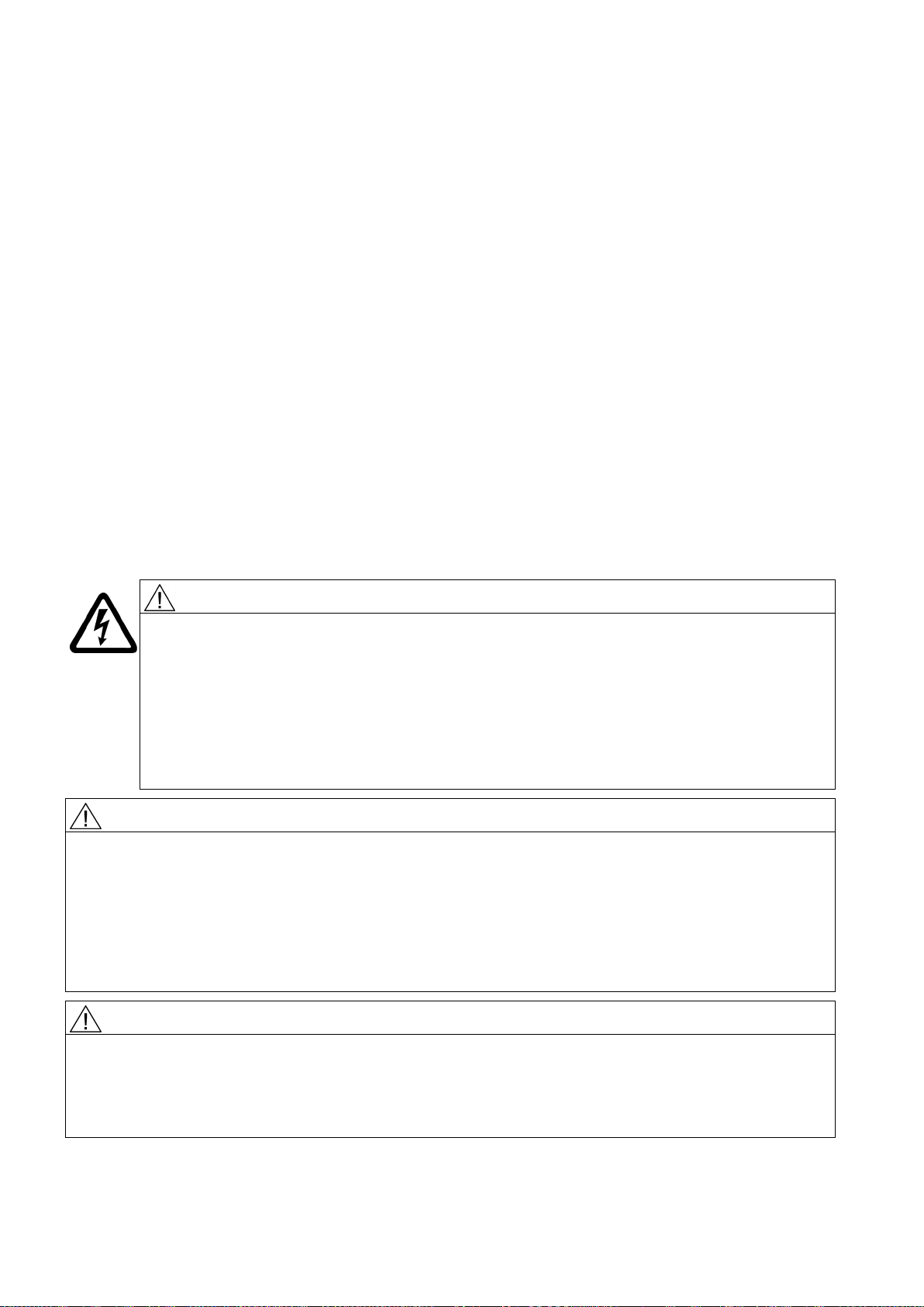
Basic type of construction
code
Diagram
Other methods of installation
Diagram
Basic type of construction
code
Diagram
Other methods of installation
Diagram
Basic type of construction
code
Diagram
3.2.7
Degree of protection
3.2.8
Environmental conditions
Limit values for the standard version
Installation altitude
≤ 1000 m
4
Preparing for use
4.1
Safety-related aspects to consider when configuring the plant
IM B5 (IM 3001)
IM V3 (IM 3031)
IM B14 (IM 3601)
IM V19 (IM 3631)
IM B35 (IM 2001)
IM B34 (IM 2101)
IM V1 (IM 3011)
IM V18 (IM 3611)
The machine has a type of protection as stamped on the rating plate, and can be installed in dusty or humid environments.
Ambient temperature -20 °C to +50 °C
Air with normal oxygen content, usually 21 % (V/V)
If the environmental conditions are different from the details listed here, then the values on the rating plate will apply.
Good planning and preparation of machine applications are essential in terms of keeping installation simple and avoiding
errors, ensuring safe operation, and allowing access to the machine for servicing and corrective maintenance.
This chapter outlines what you need to consider when configuring your plant in relation to this machine and the preparations
you need to make before the machine is delivered.
A number of residual risks are associated with the machine. These are described in the chapter titled "Safety information"
(Page 1) and in related sections.
Take appropriate safety precautions (covers, barriers, markings, etc.) to ensure the machine is operated safely within your
plant.
1LE7
6 A5E36065207, 04/2018

4.2
Observing the operating mode
4.3
Delivery
Checking the delivery for completeness
4.4
Transportation and storage
4.4.1
Requirements for safe lifting and transporting
Preconditions for safe lifting and transporting
Center of gravity not centered
4.4.2
Transport
Risk of dropping and swinging when transported suspended
Observe the machine's operating mode. Use a suitable control system to prevent overspeeds, thus protecting the machine
from damage.
The drive systems are put together on an individual basis. When you take receipt of the delivery, please check immediately
whether the items delivered are in accordance with the accompanying documents. Siemens will not accept any claims
relating to items missing from the delivery and which are submitted at a later date.
● Report any apparent transport damage to the delivery agent immediately.
● Report any apparent defects/missing components to the appropriate SIEMENS office immediately.
Archive the safety and commissioning notes provided in the scope of delivery as well as the optionally available operating
instructions so that these documents are always easily accessible.
The rating plate optionally enclosed as a loose item with the delivery is provided to enable the motor data to be attached on
or near the machine or installation.
Observe the following when carrying out any work on the machine:
● Comply with the general safety instructions (Page 1)
● Comply with the applicable national and sector-specific regulations.
● When using the machine within the European Union, comply with the specifications laid down in EN 50110-1 regarding
safe operation of electrical equipment.
If you do not transport or lift the machine in a position appropriate for its construction, the machine can tip, slip into the lifting
equipment or fall down. This can result in death, serious injury or material damage.
● Use only the load carrying device on the stator frame for lifting.
● Use the load carrying device appropriate for the machine position.
● Only use suitable rope guiding or spreading devices.
If the center of gravity of a load is not located centrally between the attachment points, the machine can tip over or slip out of
the lifting equipment and fall when it is being transported or lifted. This can result in death, serious injury or material damage.
● Comply with the handling instructions on the machine when transporting it.
● Be aware of the possibility of different loads on the sling ropes or lifting straps and the carrying capacity of the lifting
equipment.
● Always take account of the center of gravity when transporting or lifting the machine. If the center of gravity is not located
centrally between the attachment points, then position the hoisting hook above the center of gravity.
If you transport the motor suspended from cables or ropes, the cables or ropes can break, e.g. as a result of damage.
Further, if not adequately attached, the motor can swing. This can result in death, serious injury, or material damage.
● Use additional, suitable lifting equipment for transport and during installation.
● Two cables alone must be able to carry the complete load.
● Prevent the lifting equipment from sliding by appropriately securing it.
1LE7
A5E36065207, 04/2018
7
Toppling over or slipping of the motor
Note
When lifting the machines for transport, only lift them in a position that corresponds to their basic construction type.
4.4.3
Storage
Storing outdoors
NOTICE
Damage to the motor
● When using 2-cable lifting equipment, ensure that the maximum angle of inclination is ≤45° according to ISO 3266 (DIN
580).
● Align the eyebolts so that the cables used for lifting are aligned with the planes of the eyebolts.
The motor can slide or topple over if it is not correctly lifted or transported. This can result in death, serious injury, or material
damage.
● Use all the lifting eyes on the machine.
● When using the lifting eyes on the machine, do not attach any additional loads or weight. The lifting eyes are only
designed for the weight of the machine itself.
● Any eyes that are screwed in must be tightly fastened.
● Eyebolts must be screwed in right up to their supporting surface.
● Comply with the permissible eyebolt loads.
● When necessary, use suitably dimensioned lifting equipment, for example hoisting straps (EN1492-1) and load restraints
(EN12195-2).
The type of construction of the machine is stated on the rating plate.
If any transport locks are in place, remove them before commissioning. Store the transport locks or disable them. Use the
transport locks when transporting the motors again or reactivate the transport locks.
The machines are packed in different ways depending on how they are transported and their size. If not otherwise
contractually agreed, the packaging corresponds to the packing guidelines according to ISPM (International Standards for
Phytosanitary Measures).
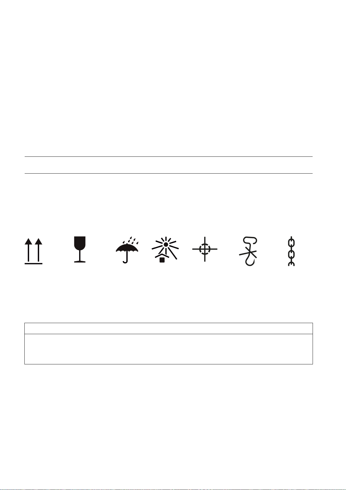
Comply with the images shown on the packaging. Their meaning is as follows:
Hand hooks
forbidden
Attach
here
goods
Protect
against mois-
Up Fragile
Damage can occur if incorrectly stored.
Take all precautions to protect the motor under extreme climatic conditions, e.g. salt-laden and/or dusty, moist/humid
atmospheres.
Choose a dry storage location which is safe from flooding and free from vibration. Repair any damage to the packaging
before putting the equipment into storage if this is necessary to ensure proper storage conditions. In order to ensure
protection against ground moisture, locate machines, equipment and crates on pallets, wooden beams or foundations.
Prevent equipment from sinking into the ground. Do not impede air circulation under the stored items.
Covers or tarpaulins used to protect the equipment against the weather must not come into contact with the surfaces of the
equipment. Use wooden spacer elements to ensure that air can circulate freely around the equipment.
Protect
against heat
ture
Center of
gravity
1LE7
8 A5E36065207, 04/2018

Storing indoors
Bare metal surfaces
Condensation drain hole
Storage temperature
Storage time
Open bearings
Closed bearings
NOTICE
Storage
• If required, contact the service center, or technically coordinate outdoors use.
4.5
Electromagnetic compatibility
Note
If the torque levels are very unequal (e.g. when a reciprocating compressor is being driven), a non
current will be induced whose harmonics can have an impermissibl
interference emissions as a result.
Note
Converter
•
•
•
•
•
, disturbance voltages caused by the converter may occur on
the sensor cable.
The storage rooms must provide protection against extreme weather conditions. They must be dry, free from dust, frost and
vibration and well ventilated.
For transport, the bare surfaces (shaft ends, flange surfaces, centering edges) should be coated with an anti-corrosion agent
which will last for a limited amount of time (<6 months). Apply suitable anti-corrosion measures for longer storage times.
Open any condensation drain holes to drain the condensation depending on the environmental conditions, every six months
at the latest.
Permissible temperature range: -20 °C to +50 °C
Maximum permissible air humidity: 60%
For machines that have a special design regarding the ambient temperature in the operating state or the installation altitude,
other conditions could apply regarding the storage temperature. In this case, refer to the machine rating plate for data on the
ambient temperature and installation altitude.
Turn the shaft once every year to avoid bearing brinelling. Prolonged storage periods reduce the useful life of the bearing
grease (aging).
● For open bearings, e.g. 1Z, check the status of the grease when stored for longer than 12 months.
● Replace the grease if it is identified that the grease has lost its lubricating properties or is polluted. The consistency of the
grease will change if condensation is allowed to enter.
● For closed bearings, replace the DE and NDE bearings after a storage time of 48 months.
The motor can be damaged if you use it or store it unprotected outdoors.
• Protect the motor against intensive solar radiation, rain, snow, ice and dust. Use a superstructure or additional cover,
for example.
If operated with a frequency converter, the emitted interference varies in strength, depending on the design of the
converter (type, interference suppression measures, manufacturer).
Avoid that the specified limit values stipulated for the drive system (consisting of the motor and converter) are exceeded.
You must observe the EMC information from the manufacturer of the converter.
The most effective method of shielding is to conductively connect a shielded machine supply cable to the metal terminal
box of the machine (with a metal screw connection) over a large surface area.
On machines with integrated sensors (e.g. PTC thermistors)
1LE7
A5E36065207, 04/2018
e effect on the supply system and cause impermissible
-sinusoidal machine
9

4.6
Converter operation
4.6.1
Parameterizing the converter
4.6.2
Converter input voltage
NOTICE
Material damage caused by an excessively high supply voltage
• Comply with the peak voltages as laid down in the guidelines above.
4.6.3
Reducing bearing currents during operation with converter (low voltage)
:
● If the design of the motor requires connection to a particular converter type, the rating plate will contain corresponding
additional information.
● Correctly parameterize the converter. Parameterizing data can be taken from the machine rating plates.
You can find parameter data here:
– In the operating instructions for the converter.
– In the SIZER engineering tool
– In the SINAMICS Configuration Manuals.
● Do not exceed the specified maximum speed limit n
supplementary plate for converter operation as the highest speed.
● Check that the machine is cooled sufficiently for commissioning purposes.
The insulation system of SIMOTICS machines significantly exceeds the requirements of stress category B (IVIC B = medium
stress). If voltage peaks higher than those specified according to IVIC B can occur, then observe the data in the respective
Catalog:
● For a line voltage (converter input voltage) up to max. 480 V and operation connected to a SINAMICS G / SINAMICS S
converter with uncontrolled/controlled infeed: Comply with the guidelines for configuring motor and converter.
● For line voltages (converter input voltages) higher than 480 V, motors, which are ordered for converter operation, have
an appropriate insulation system.
● Operation with a converter from another manufacturer: Comply with the permissible voltage peaks according to
IEC 60034-18-41 in accordance with stress category C, dependent on the particular line voltage (converter input voltage)
and the motor insulation system.
. You can either find this on the rating plate n
max
or on the
max
The insulation system will be damaged if the supply voltage is too high for the insulation system. This can completely
destroy the machine.
Taking the following actions will reduce the bearing currents:
● Ensure that the contacts are made over a large area. Solid copper cables are not suitable for high-frequency grounding
because of the skin effect.
Equipotential bonding conductors:
Use equipotential bonding conductors:
● between motor and driven machine
● between motor and converter
● between the terminal box and the RF grounding point at the motor enclosure.
Selecting and connecting the cable
As far as possible, use symmetrically arranged, shielded connection cables. The cable shielding, made up of as many
strands as possible, must have good electrical conductivity. Braided shields made of copper or aluminum are very suitable.
● The shield is connected at both ends, at the motor and converter.
● To ensure good discharging of high-frequency currents, provide contacting over a large surface area:
– as contact established through 360° at the converter
– at the motor, for instance with EMC glands at the cable entries.
1LE7
10 A5E36065207, 04/2018
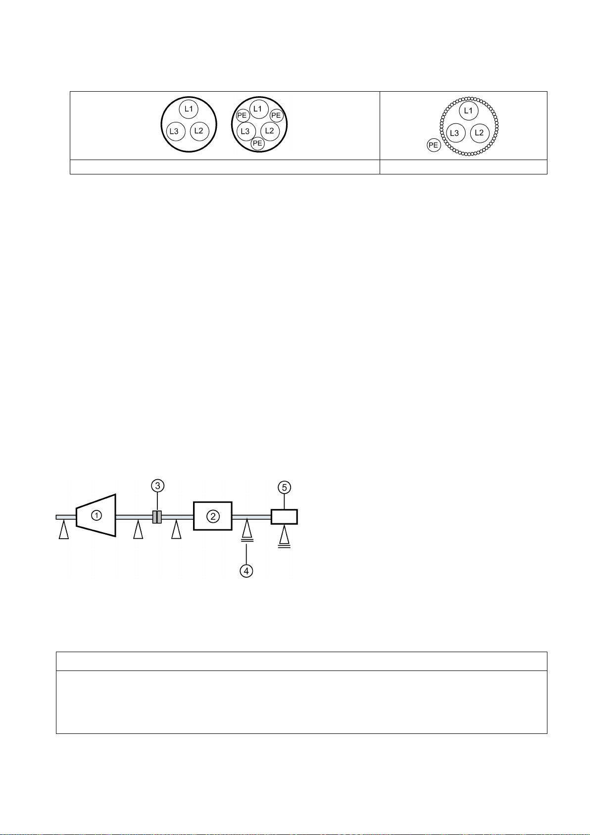
Concentric copper or aluminum shield
Steel armor
Overall system design
4.6.4
Insulated bearings when operated with a converter
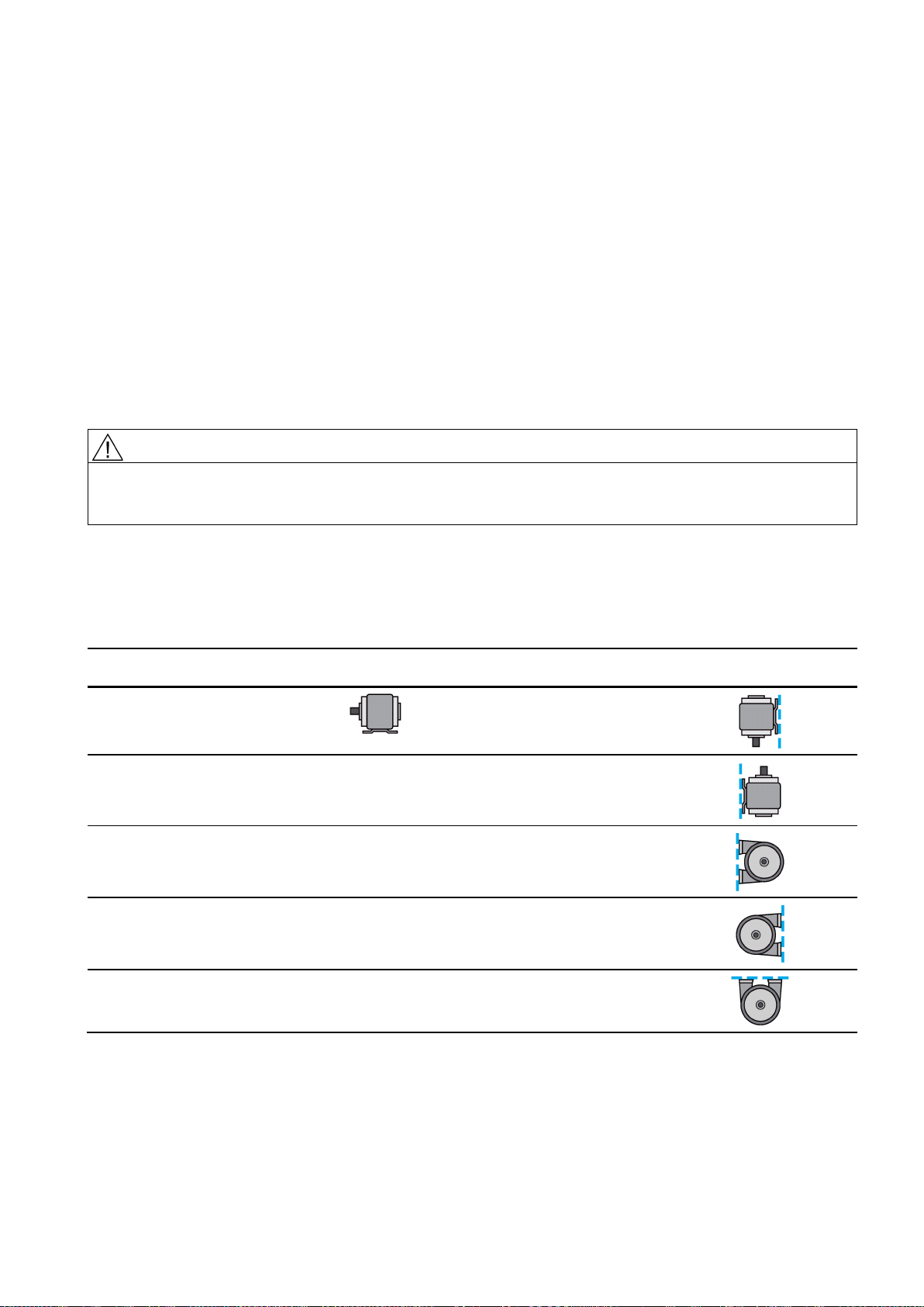
①
Driving machine
④
Insulated bearings
②
Motor
⑤
Insulated tachometer fitting
③
Coupling
NOTICE
Bearing damage
Please contact the service center if necessary.
● If the cable shield is connected as described, then it ensures the specified equipotential bonding between the motor
enclosure and converter. A separate RF equipotential bonding conductor is then not necessary.
● If the cable shield is not connected due to special secondary conditions, or not adequately connected, then the specified
equipotential bonding is not provided. In this particular case, use a separate RF equipotential bonding conductor:
– Between the motor enclosure and protective ground rail of the converter.
– Between motor enclosure and driven machine
– Use braided flat copper straps or high-frequency cables with finely-stranded conductors for the separate RF
equipotential bonding cable.
– Ensure that the contacts are made over a large area.
To specifically reduce bearing currents, you must consider the system as a whole, which comprises the motor, converter,
and driven machine. The following measures support you when reducing bearing currents and help to avoid damage:
● In the overall system, set up a properly meshed grounding system with low impedance.
● Use the common-mode filter (damping cores) at the converter output.
● Limit the rise in voltage by using output filters. Output filters dampen the harmonic content in the output voltage.
● The operating instructions for the converter are not part of this documentation. Refer to the configuration information for
the converter.
If the machine is operated from a low-voltage converter, insulated bearings are fitted at the NDE and an insulated encoder
with insulated bearings (option).
Comply with the plates on the machine relating to bearing insulation and possible bridges.
Figure 4-1 Schematic representation of a single drive
The bearing insulation must not be bridged. Bearing currents can damage bearings.
• Also for subsequent installation work, such as the installation of an automatic lubrication system or a non-insulated
vibration sensor, make sure that the bearing insulation cannot be bridged.
•
1LE7
A5E36065207, 04/2018
11
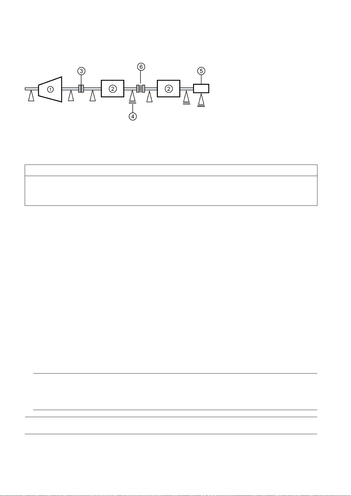
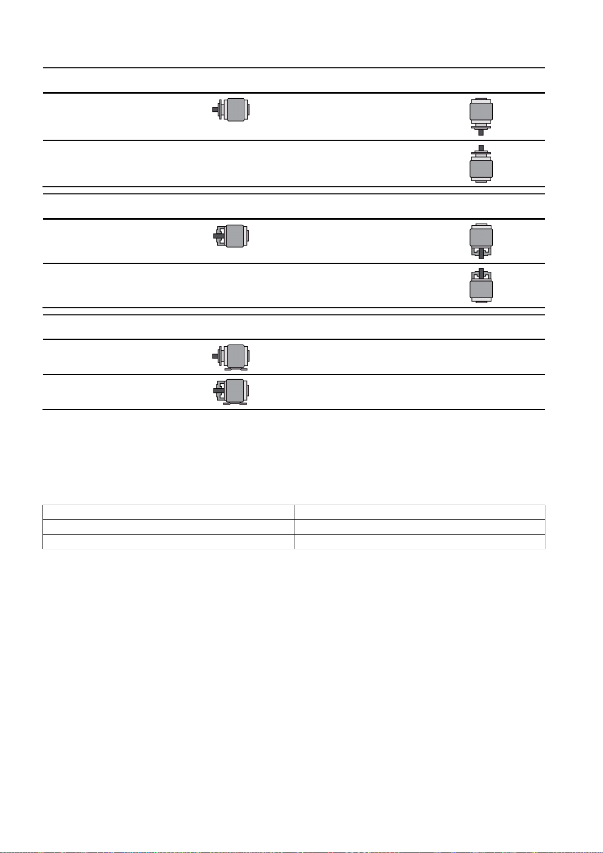
Tandem operation
①
Driving machine
④
Insulated bearings
②
Motor
⑤
Insulated tachometer fitting
③
Coupling
⑥
Insulated coupling
NOTICE
Bearing damage
Use an insulated coupling to link the motors.
5
Installation
5.1
Conformity
Loss of conformity with European directives
5.2
Preparing for installation
Note
Measure the insulation resistance of the winding before starting installation work
Measure the insulation resistance of the winding before starting any installation work. If the insulation resistance lies
below the specified value, take appropriate remedia
being removed again and transported.
Note
Note also the technical data on the rating plates on the motor enclosure
If you connect two motors in series in "tandem operation", install an insulated coupling between the motors.
Figure 4-2 Schematic representation of a tandem drive
Bearing currents can flow if the coupling between the motors of the tandem drive is not insulated. This can damage the DE
bearings of both motors.
•
Observe the following when carrying out any work on the machine:
● Comply with the general safety instructions (Page 1)
● Comply with the applicable national and sector-specific regulations.
● When using the machine within the European Union, comply with the specifications laid down in EN 50110-1 regarding
safe operation of electrical equipment.
In the delivery state, the machine corresponds to the requirements of the European directives. Unauthorized changes or
modifications to the machine lead to the loss of conformity with European directives and the loss of warranty.
The following requirements must be satisfied prior to starting installation work:
● Staff have access to the operating and installation instructions.
● The machine is unpacked and ready for mounting at the installation location.
l measures. These remedial measures may necessitate the machine
.
1LE7
12 A5E36065207, 04/2018
 Loading...