

Page 1

© Siemens AG 2016 - 2017. All rights reserved
A5E37208904-003, 04/2017
1
SINAMICS V90, SIMOTICS S-1FL6
PROFINET (PN) interface
Getting Started
Compact Operating Instructions
Table of contents
1 Fundamental safety instructions .............................................................................................................................. 3
1.1 General safety instructions ...................................................................................................................... 3
1.2 Handling electrostatic sensitive devices (ESD) ....................................................................................... 7
1.3 Industrial security .................................................................................................................................... 7
1.4 Residual risks of power drive systems..................................................................................................... 8
2 General information ................................................................................................................................................ 9
2.1 Deliverables ............................................................................................................................................. 9
2.1.1 Drive components.................................................................................................................................... 9
2.1.2 Motor components ................................................................................................................................. 14
2.2 Device combination ............................................................................................................................... 17
2.3 Accessories ........................................................................................................................................... 20
2.4 Function list ........................................................................................................................................... 22
2.5 Technical data ....................................................................................................................................... 23
2.5.1 Technical data - servo drives ................................................................................................................. 23
2.5.2 Technical data - servo motors ............................................................................................................... 25
2.5.3 Address of CE-authorized manufacturer ............................................................................................... 28
3 Mounting .............................................................................................................................................................. 29
3.1 Mounting the drive ................................................................................................................................. 29
3.2 Mounting the motor................................................................................................................................ 33
4 Connecting ........................................................................................................................................................... 40
4.1 System connection ................................................................................................................................ 40
4.2 Main circuit wiring .................................................................................................................................. 45
4.2.1 Line supply - L1, L2, L3 ......................................................................................................................... 45
4.2.2 Motor power - U, V, W ........................................................................................................................... 46
4.3 Control/Status interface - X8 ................................................................................................................. 48
4.3.1 Interface definition ................................................................................................................................. 48
4.3.2 Standard wiring ..................................................................................................................................... 48
4.4 24 V power supply/STO ......................................................................................................................... 49
4.5 Encoder interface - X9 ........................................................................................................................... 51
4.6 External braking resistor - DCP, R1 ...................................................................................................... 54
4.7 Motor holding brake ............................................................................................................................... 54
4.8 PROFINET interface - X150 .................................................................................................................. 55
5 Commissioning ..................................................................................................................................................... 56
5.1 Introduction to the BOP ......................................................................................................................... 57
5.2 Initial commissioning in JOG mode ....................................................................................................... 62
5.3 Commissioning in basic positioner control mode (EPOS) ..................................................................... 63
Page 2

Getting Started
2 A5E37208904-003, 04/2017
5.4 Commissioning in speed control mode (S) ............................................................................................ 64
5.5 Commissioning control functions........................................................................................................... 65
5.5.1 Speed limit ............................................................................................................................................ 65
5.5.2 Torque limit ........................................................................................................................................... 66
5.5.3 EJOG .................................................................................................................................................... 67
6 PROFINET communication ....................................................................................................................................68
6.1 Supported telegrams ............................................................................................................................. 68
6.2 I/O data signals ..................................................................................................................................... 70
6.3 Control word definition .......................................................................................................................... 71
6.3.1 STW1 control word (for telegrams 1, 2, 3, 5) ........................................................................................ 71
6.3.2 STW2 control word (for telegrams 2, 3, 5) ............................................................................................ 72
6.3.3 STW1 control word (for telegrams 102, 105) ........................................................................................ 72
6.3.4 STW2 control word (for telegrams 102, 105) ........................................................................................ 73
6.3.5 STW1 control word (for telegrams 7, 9, 110, 111) ................................................................................ 74
6.3.6 STW2 control word (for telegrams 9, 110, 111) .................................................................................... 74
6.3.7 G1_STW encoder 1 control word .......................................................................................................... 75
6.3.8 SATZANW control word ........................................................................................................................ 75
6.3.9 MDI_MOD control word ......................................................................................................................... 76
6.3.10 POS_STW control word ........................................................................................................................ 76
6.3.11 POS_STW1 positioning control word .................................................................................................... 77
6.3.12 POS_STW2 positioning control word .................................................................................................... 77
6.4 Status word definition ............................................................................................................................ 78
6.4.1 ZSW1 status word (for telegrams 1, 2, 3, 5) .......................................................................................... 78
6.4.2 ZSW2 status word (for telegram 2, 3, 5) ............................................................................................... 78
6.4.3 ZSW1 status word (for telegrams 102, 105) .......................................................................................... 79
6.4.4 ZSW2 status word (for telegram 102, 105) ........................................................................................... 79
6.4.5 ZSW1 status word (for telegram 7, 9, 110, 111) ................................................................................... 80
6.4.6 ZSW2 status word (for telegrams 9, 110, 111) ...................................................................................... 80
6.4.7 G1_ZSW encoder 1 status word ........................................................................................................... 81
6.4.8 MELDW status word ............................................................................................................................. 81
6.4.9 POS_ZSW1 positioning status word ..................................................................................................... 82
6.4.10 POS_ZSW2 positioning status word ..................................................................................................... 82
7 Parameters ...........................................................................................................................................................83
7.1 Overview ............................................................................................................................................... 83
7.2 Parameter list ........................................................................................................................................ 84
8 Diagnostics ......................................................................................................................................................... 114
8.1 Overview ............................................................................................................................................. 114
8.2 List of faults and alarms ...................................................................................................................... 116
Page 3
Getting Started
A5E37208904-003, 04/2017
3
1
Fundamental safety instructions
1.1
General safety instructions
DANGER
Danger to life due to live parts and other energy sources
Death or serious injury can result when live parts are touched.
• Only work on electrical devices when you are qualified for this job.
• Always observe the country-specific safety rules.
Generally, six steps apply when establishing safety:
1. Prepare for shutdown and notify all those who will be affected by the procedure.
2. Disconnect the machine from the supply.
– Switch off the machine.
– Wait until the discharge time specified on the warning labels has elapsed.
– Check that it really is in a no-voltage condition, from phase conductor to phase conductor and phase
conductor to protective conductor.
– Check whether the existing auxiliary supply circuits are de-energized.
– Ensure that the motors cannot move.
3. Identify all other dangerous energy sources, e.g. compressed air, hydraulic systems, or water.
4. Isolate or neutralize all hazardous energy sources by closing switches, grounding or short-circuiting or
closing valves, for example.
5. Secure the energy sources against switching on again.
6. Ensure that the correct machine is completely interlocked.
After you have completed the work, restore the operational readiness in the inverse sequence.
WARNING
Danger to life through a hazardous voltage when connecting an unsuitable power supply
Touching live components can result in death or severe injury.
• Only use power supplies that provide SELV (Safety Extra Low Voltage) or PELV- (Protective Extra Low
Voltage) output voltages for all connections and terminals of the electronics modules.
WARNING
Danger to life when live parts are touched on damaged motors/devices
Improper handling of motors/devices can damage them.
For damaged motors/devices, hazardous voltages can be present at the enclosure or at exposed components.
• Ensure compliance with the limit values specified in the technical data during transport, storage and
operation.
•
Do not use any damaged motors/devices.
WARNING
Danger to life through electric shock due to unconnected cable shields
Hazardous touch voltages can occur through capacitive cross-coupling due to unconnected cable shields.
• As a minimum, connect cable shields and the cores of cables that are not used at one end at the grounded
housing potential.
Page 4
Getting Started
4 A5E37208904-003, 04/2017
WARNING
Danger to life due to electric shock when not grounded
For missing or incorrectly implemented protective conducto
r connection for devices with protection class I, high
voltages can be present at open, exposed parts, which when touched, can result in death or severe injury.
•
Ground the device in compliance with the applicable regulations.
WARNING
Danger to life due to electric shock when opening plug connections in operation
When opening plug connections in operation, arcs can result in severe injury or death.
• Only open plug connections when the equipment is in a no-
voltage state, unless it has been explicitly stated
that they can be opened in operation.
WARNING
Danger to life through electric shock due to the residual charge of the power component capacitors
Because of the capacitors, a hazardous voltage is present for up to 5 minutes after the power supply has been
switched off. Contact with live parts can result in death or serious injury.
• Wait for 5 minutes before you check that the unit really is in a no-voltage condition and start work.
NOTICE
Material damage due to loose power connections
Insufficient tightening torques or vibrations can result in loose electrical connections. This can result in damage due to fire,
device defects or malfunctions.
• Tighten all power connections with the specified tightening torques, e.g. line supply connection, motor connection, DC
link connections.
•
Check all power connections at regular intervals. This applies in particular after transport.
WARNING
Danger to life due to fire spreading if housing is inadequate
Fire and smoke development can cause severe personal injury or material damage.
• Install devices without a protective housing in a metal control cabinet (or protect the device by another equivalent
measure) in such a way that contact with fire is prevented.
•
Ensure that smoke can only escape via controlled and monitored paths.
WARNING
Danger to life from electromagnetic fields
Electromagnetic fields (EMF) are generated by the operation of electrical power equipment, such as transformers,
converters, or motors.
People with pacemakers or implants are at particular risk in the immediate vicinity of this equipment.
• If you have a heart pacemaker or implant, maintain a minimum distance of 2 m from electrical power equipment.
WARNING
Danger to life from permanent-magnet fields
Even when switched off, electric motors with permanent magnets represent a potential risk for persons with heart
pacemakers or implants if they are close to converters/motors.
• If you have a heart pacemaker or implant, maintain a minimum distance of 2 m.
• When transporting or storing permanent-magnet motors always use the original packing materials with the warning
labels attached.
• Clearly mark the storage locations with the appropriate warning labels.
•
IATA regulations must be observed when transported by air.
Page 5
Getting Started
A5E37208904-003, 04/2017
5
WARNING
Danger to life through unexpected movement of machines when using mobile wireless devices or mobile phones
Using mobile wireless devices or mobile phones with a transmit power > 1 W closer than approx. 2 m to the components
may cause the devices to malfunction, influence the functional safety of machines therefore putting people at risk or
causing material damage.
• Switch the wireless devices or mobile phones off in the immediate vicinity of the components.
WARNING
Danger to life due to the motor catching fire in the event of insulation overload
There is higher stress on the motor insulation through a ground fault in an IT system. If the insulation fails, it is possible that
death or severe injury can occur as a result of smoke and fire.
• Use a monitoring device that signals an insulation fault.
•
Correct the fault as quickly as possible so the motor insulation is not overloaded.
WARNING
Danger to life due to fire if overheating occurs because of insufficient ventilation clearances
Inadequate ventilation clearances can cause overheating of components with subsequent fire and smoke. This can cause
severe injury or even death. This can also result in increased downtime and reduced service lives for devices/systems.
• Ensure compliance with the specified minimum clearance as ventilation clearance for the respective component.
WARNING
Danger of an accident occurring due to missing or illegible warning labels
Missing or illegible warning labels can result in accidents involving death or serious injury.
• Check that the warning labels are complete based on the documentation.
• Attach any missing warning labels to the components, in the national language if necessary.
•
Replace illegible warning labels.
NOTICE
Device damage caused by incorrect voltage/insulation tests
Incorrect voltage/insulation tests can damage the device.
• Before carrying out a voltage/insulation check of the system/machine, disconnect the devices as all converters and
motors have been subject to a high voltage test by the manufacturer, and therefore it is not necessary to perform an
additional test within the system/machine.
WARNING
Danger to life when safety functions are inactive
Safety functions that are inactive or that have not been adjusted accordingly can cause operational faults on machines that
could lead to serious injury or death.
• Observe the information in the appropriate product documentation before commissioning.
• Carry out a safety inspection for functions relevant to safety on the entire system, including all safety-related
components.
• Ensure that the safety functions used in your drives and automation tasks are adjusted and activated through
appropriate parameterizing.
• Perform a function test.
• Only put your plant into live operation once you have guaranteed that the functions relevant to safety are running
correctly.
Page 6
Getting Started
6 A5E37208904-003, 04/2017
Note
Important safety notices for Safety Integrated functions
If you want to use Safety Integrated functions, you must observe the safety notices in the Safety Integrated manuals
.
WARNING
Danger to life or malfunctions of the machine as a result of incorrect or changed parameterization
As a result of incorrect or changed parameterization, machines can malfunction, which in turn can lead to injuries or death.
• Protect the parameterization (parameter assignments) against unauthorized access.
•
Respond to possible malfunctions by applying suitable measures (e.g. EMERGENCY STOP or EMERGENCY OFF).
WARNING
Risk of injury caused by moving parts or parts that are flung out
Touching moving motor parts or drive output elements and loose motor parts that are flung out (e.g. feather keys) in
operation can result in severe injury or death.
• Remove any loose parts or secure them so that they cannot be flung out.
• Do not touch any moving parts.
• Safeguard all moving parts using the appropriate safety guards.
WARNING
Danger to life due to fire if overheating occurs because of insufficient cooling
Inadequate cooling can cause overheating resulting in death or severe injury as a result of smoke and fire. This can also
result in increased failures and reduced service lives of motors.
•
Comply with the specified coolant requirements for the motor.
WARNING
Danger to life due to fire as a result of overheating caused by incorrect operation
When incorrectly operated and in the case of a fault, the motor can overheat resulting in fire and smoke. This can result in
severe injury or death. Further, excessively high temperatures destroy motor components and result in increased failures
as well as shorter service lives of motors.
• Operate the motor according to the relevant specifications.
• Only operate the motors in conjunction with effective temperature monitoring.
•
Immediately switch off the motor if excessively high temperatures occur.
CAUTION
Risk of injury due to touching hot surfaces
In operation, the motor can reach high temperatures, which can cause burns if touched.
• Mount the motor so that it is not accessible in operation.
Measures when maintenance is required:
• Allow the motor to cool down before starting any work.
•
Use the appropriate personnel protection equipment, e.g. gloves.
Page 7
Getting Started
A5E37208904-003, 04/2017
7
1.2
Handling electrostatic sensitive devices (ESD)
Electrostatic sensitive devices (ESD) are individual components, integrated circuits, modules or devices that may be
damaged by either electric fields or electrostatic discharge.
NOTICE
Damage through electric fields or electrostatic discharge
Electric fields or electrostatic discharge can cause malfunctions through damaged individual components,
integrated circuits, modules or devices.
•
Only pack, store, transport and send electronic components, modules or devices in their original packaging
or in other suitable materials, e.g conductive foam rubber of aluminum foil.
• Only touch components, modules and devices when you are grounded by one of the following methods:
– Wearing an ESD wrist strap
– Wearing ESD shoes or ESD grounding straps in ESD areas with conductive flooring
• Only place electronic components, modules or devices on conductive surfaces (table with ESD surface,
conductive ESD foam, ESD packaging, ESD transport container).
1.3
Industrial security
Note
Industrial security
Siemens provides products and solutions with industrial security functions that support the secure operation of plants,
s
ystems, machines and networks.
In order to protect plants, systems, machines and networks against cyber threats, it is necessary to implement
– and
continuously maintain
– a holistic, state-of-the-art industrial security concept. Siemens products and solut
ions only represent
one component of such a concept.
The customer is responsible for preventing unauthorized access to its plants, systems, machines and networks. Systems,
machines and components should only be connected to the enterprise network or the internet if and to the extent necessary
and with appropriate security measures (e.g. use of firewalls and network segmentation) in place.
Additionally, Siemens’ guidance on appropriate security measures should be taken into account. For more information about
industrial security, please visit:
Industrial security (
http://www.siemens.com/industrialsecurity).
Siemens’ products and solutions undergo continuous development to make them more secure. Sie
mens strongly
recommends to apply product updates as soon as available and to always use the latest product versions. Use of product
versions that are no longer supported, and failure to apply latest updates may increase customer’s exposure to cyber
threat
s.
To stay informed about product updates, subscribe to the Siemens Industrial Security RSS Feed at:
Industrial security (
http://www.siemens.com/industrialsecurity).
WARNING
Danger to life as a result of unsafe operating states resulting from software manipulation
Software manipulations (e.g. viruses, trojans, malware or worms) can cause unsafe operating states in your system that
may lead to death, serious injury, and property damage.
• Keep the software up to date.
• Incorporate the automation and drive components into a holistic, state-of-the-art industrial security concept for the
installation or machine.
• Make sure that you include all installed products into the holistic industrial security concept.
• Protect files stored on exchangeable storage media from malicious software by with suitable protection measures, e.g.
virus scanners.
Page 8

Getting Started
8 A5E37208904-003, 04/2017
1.4
Residual risks of power drive systems
When assessing the machine- or system-related risk in accordance with the respective local regulations (e.g., EC Machinery
Directive), the machine manufacturer or system installer must take into account the following residual risks emanating from
the control and drive components of a drive system:
1. Unintentional movements of driven machine or system components during commissioning, operation, maintenance, and
repairs caused by, for example,
– Hardware and/or software errors in the sensors, control system, actuators, and cables and connections
– Response times of the control system and of the drive
– Operation and/or environmental conditions outside the specification
– Condensation/conductive contamination
– Parameterization, programming, cabling, and installation errors
– Use of wireless devices/mobile phones in the immediate vicinity of electronic components
– External influences/damage
– X-ray, ionizing radiation and cosmic radiation
2. Unusually high temperatures, including open flames, as well as emissions of light, noise, particles, gases, etc., can occur
inside and outside the components under fault conditions caused by, for example:
– Component failure
– Software errors
– Operation and/or environmental conditions outside the specification
– External influences/damage
3. Hazardous shock voltages caused by, for example:
– Component failure
– Influence during electrostatic charging
– Induction of voltages in moving motors
– Operation and/or environmental conditions outside the specification
– Condensation/conductive contamination
– External influences/damage
4. Electrical, magnetic and electromagnetic fields generated in operation that can pose a risk to people with a pacemaker,
implants or metal replacement joints, etc., if they are too close
5. Release of environmental pollutants or emissions as a result of improper operation of the system and/or failure to
dispose of components safely and correctly
6. Influence of network-connected communication systems, e.g. ripple-control transmitters or data communication via the
network
For more information about the residual risks of the drive system components, see the relevant sections in the technical user
documentation.
Page 9
Getting Started
A5E37208904-003, 04/2017
9
2
General information
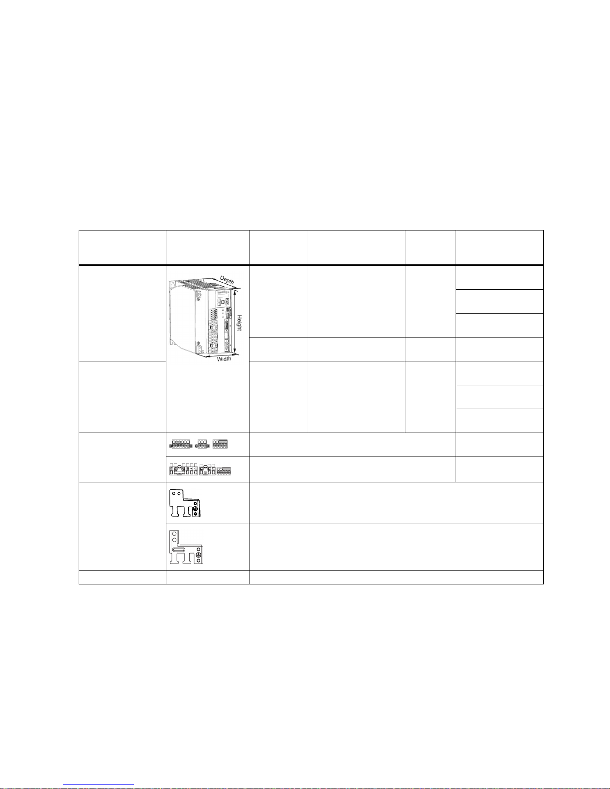
The SINAMICS V90 drives with the PROFINET interface (referred to as SINAMICS V90 PN) are available in two variants,
400 V variant and 200 V variant.
The 200 V variant is available in three frame sizes: FSB, FSC, and FSD. Frame sizes B, and C are used on the single phase
or three phase power network while frame size D is used on the three phase power network only.
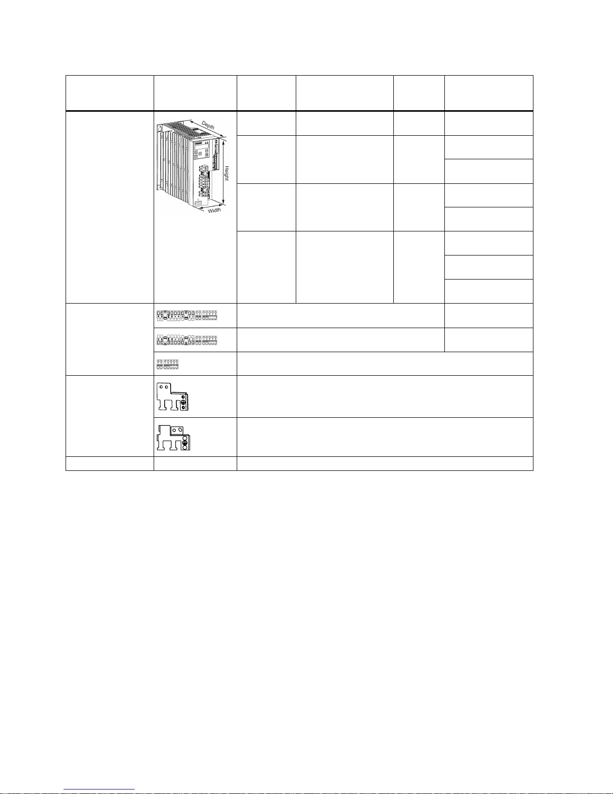
The 400 V variant is available in four frame sizes: FSAA, FSA, FSB, and FSC. All the frame sizes are used on three phase
power network only.
2.1
Deliverables
2.1.1
Drive components
Components in the SINAMICS V90 PN 200 V variant drive package
Component
Illustration
Rated power
(kW)
Outline dimension
(Width x Height x
Depth, mm)
Frame size
Article number
SINAMICS V90 PN,
single/three-phase,
200 V
0.1/0.2/0.4 55 x 170 x 170
FSB 6SL3210-5FB10-
1UF0
6SL3210-5FB10-
2UF0
6SL3210-5FB10-
4UF1
0.75 80 x 170 x 195 FSC 6SL3210-5FB10-
8UF0
SINAMICS V90 PN,
three-phase, 200 V
1.0/1.5/2.0 95 x 170 x 195 FSD 6SL3210-5FB11-
0UF1
6SL3210-5FB11-
5UF0
6SL3210-5FB12-
0UF0
Connectors
For FSB 6SL3200-0WT02-
0AA0
For FSC and FSD 6SL3200-0WT03-
0AA0
Shielding plate
For FSB
For FSC and FSD
User documentation
Information Guide
English-Chinese bilingual version
Page 10
Getting Started
10 A5E37208904-003, 04/2017
Components in the SINAMICS V90 PN 400 V variant drive package
Component
Illustration
Rated power
(kW)
Outline dimension
(Width x Height x
Depth, mm)
Frame size
Article number
SINAMICS V90 PN,
three-phase, 400 V
0.4 60 x 180 x 200 FSAA 6SL3210-5FE10-
4UF0
0.75/1.0 80 x 180 x 200 FSA 6SL3210-5FE10-
8UF0
6SL3210-5FE11-
0UF0
1.5/2.0 100 x 180 x 220 FSB 6SL3210-5FE11-
5UF0
6SL3210-5FE12-
0UF0
3.5/5.0/7.0 140 x 260 x 240 FSC 6SL3210-5FE13-
5UF0
6SL3210-5FE150UF0
6SL3210-5FE17-
0UF0
Connectors
For FSAA
6SL3200-0WT000AA0
For FSA 6SL3200-0WT01-
0AA0
For FSB and FSC *
Shielding plate
For FSAA and FSA
For FSB and FSC
User documentation Information Guide English-Chinese bilingual version
* You can obtain the connectors for SINAMICS V90 PN 400V servo drives of FSB and FSC from the connector kits for
SINAMICS V90 PN 400V servo drives of FSAA or FSA.
Page 11
Getting Started
A5E37208904-003, 04/2017
11
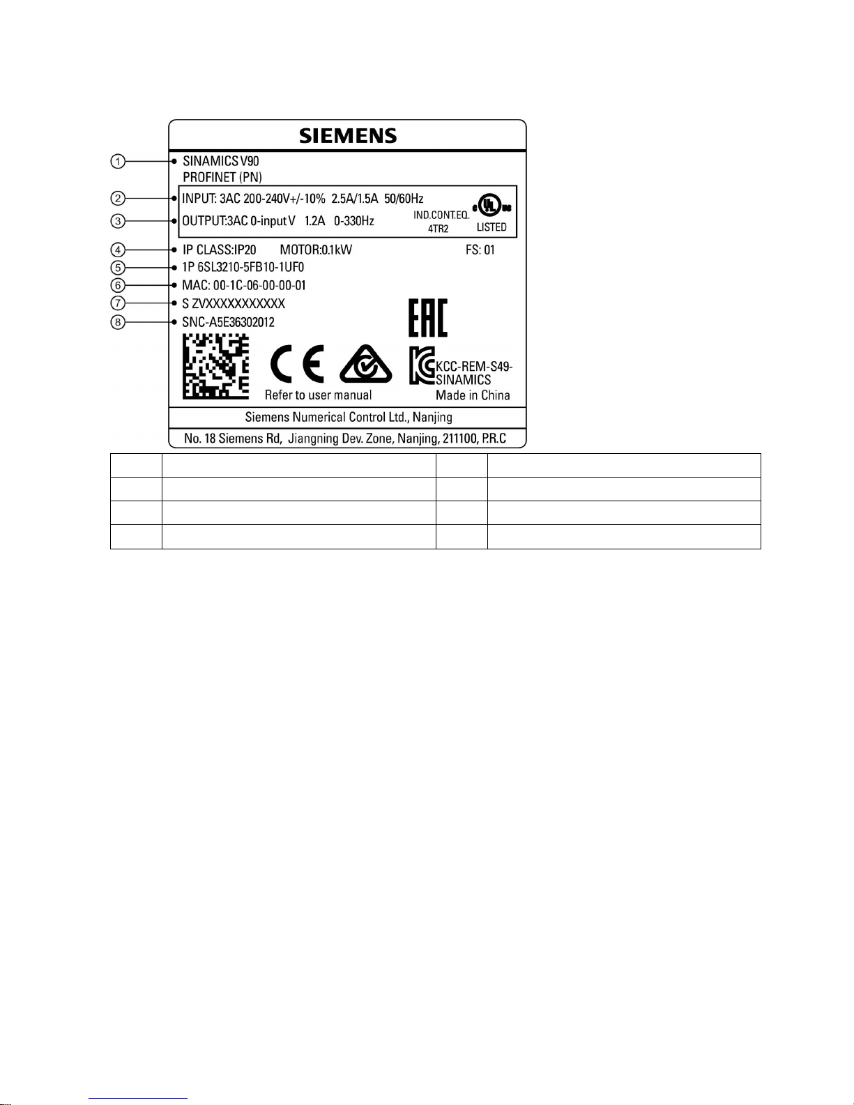
Drive rating plate (example)
①
Drive name
⑤
Article number
②
Power input
⑥
MAC address
③
Power output
⑦
Product serial number
④
Rated motor power
⑧
Part number
Page 12
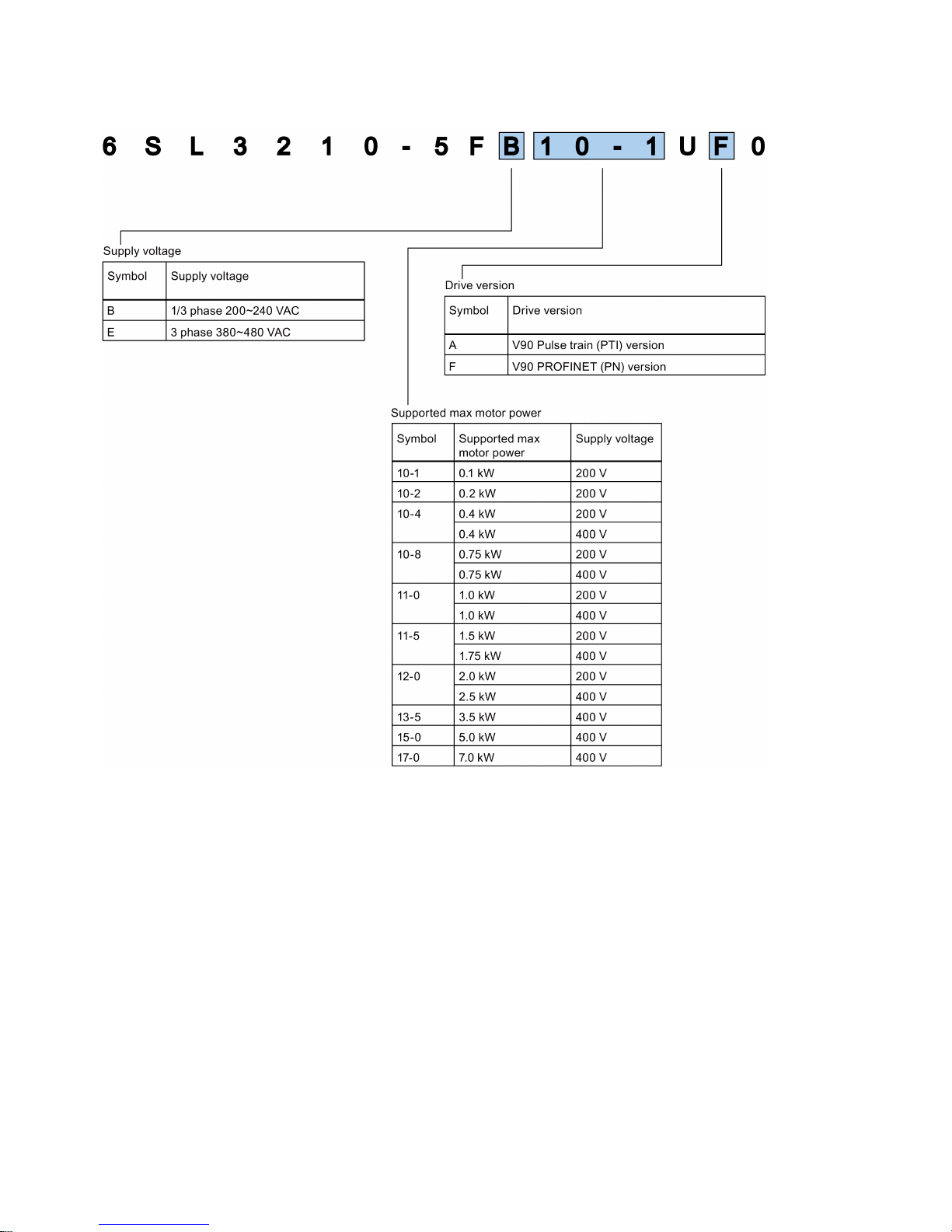
Getting Started
12 A5E37208904-003, 04/2017
Article number explanation (example)
Page 13
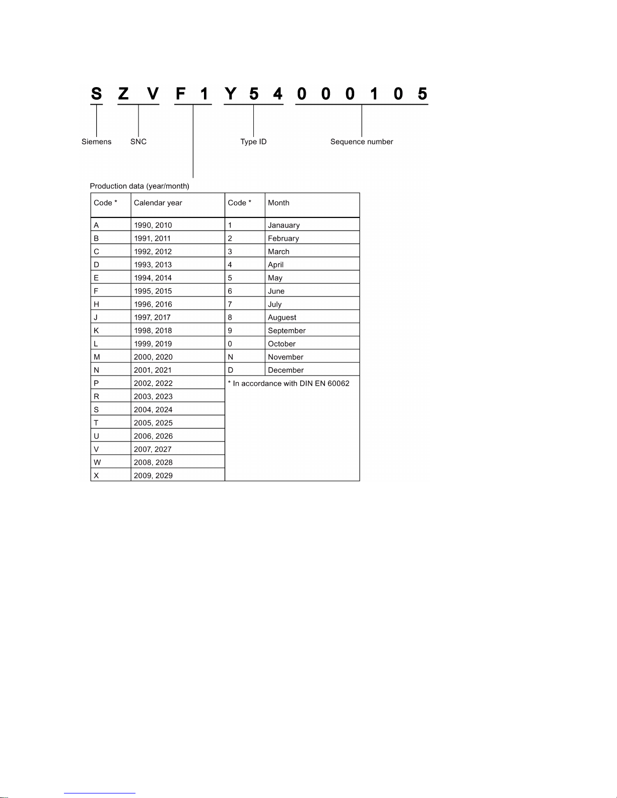
Getting Started
A5E37208904-003, 04/2017
13
Serial number explanation (example)
Page 14
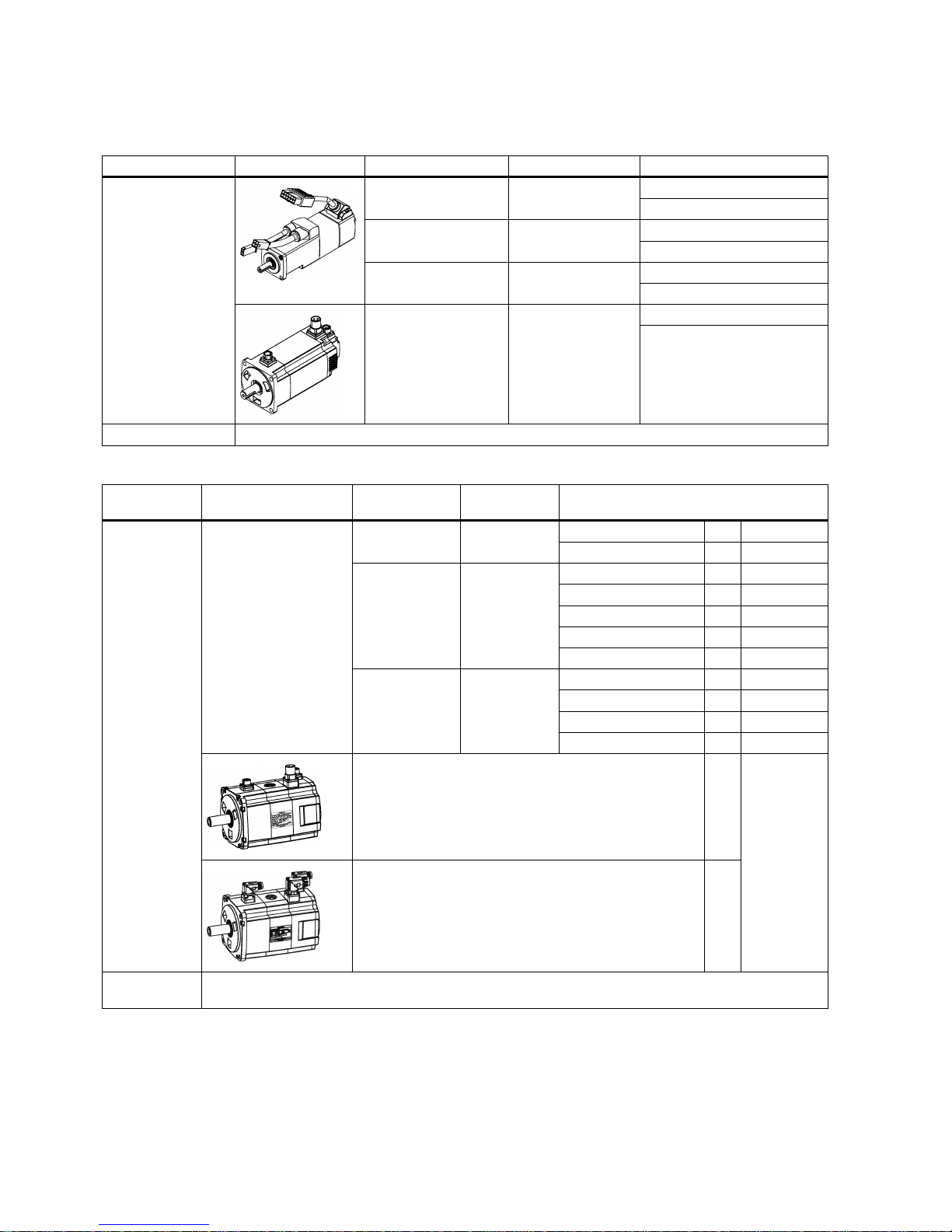
Getting Started
14 A5E37208904-003, 04/2017
2.1.2
Motor components
Components in the SIMOTICS S-1FL6 low inertia motor package
Component
Illustration
Rated power (kW)
Shaft height (mm)
Article number
SIMOTICS S-1FL6,
low inertia
0.05/0.1 20
1FL6022-2AF21-1❑❑1
1FL6024-2AF21-1❑❑1
0.2/0.4 30
1FL6032-2AF21-1❑❑1
1FL6034-2AF21-1❑❑1
0.75/1.0 40
1FL6042-2AF21-1❑❑1
1FL6044-2AF21-1❑❑1
1.5/2.0 50
1FL6052-2AF21-0❑❑1
1FL6054-2AF21-0❑❑1
User documentation
SIMOTICS S-1FL6 Servo Motors Installation Guide
Components in the SIMOTICS S-1FL6 high inertia motor package
Component
Illustration
Rated power
(kW)
Shaft height
(mm)
Article number
SIMOTICS S1FL6, high
inertia
0.4/0.75 45
1FL6042-1AF61-
❑
❑❑1
1FL6044-1AF61- ❑ ❑❑1
0.75/1.0/1.5/1.7
5/2.0
65
1FL6061-1AC61-
❑
❑❑1
1FL6062-1AC61-
❑
❑❑1
1FL6064-1AC61-
❑
❑❑1
1FL6066-1AC61-
❑
❑❑1
1FL6067-1AC61-
❑
❑❑1
2.5/3.5/5.0/7.0 90
1FL6090-1AC61-
❑
❑❑1
1FL6092-1AC61-
❑
❑❑1
1FL6094-1AC61-
❑
❑❑1
1FL6096-1AC61-
❑
❑❑1
Straight connectors with a fixed outlet direction 0
Angular connectors with a flexible outlet direction 2
User docu-
mentation
SIMOTICS S-1FL6 Servo Motors Installation Guide
Page 15

Getting Started
A5E37208904-003, 04/2017
15
Motor rating plate (example)
①
Motor type
⑦
Rated power
⑬
Rated current
②
Article number
⑧
Encoder type and resolution
⑭
Holding brake
③
Serial number
⑨
Thermal class
⑮
Motor ID
④
Rated torque
⑩
Degree of protection
⑯
Weight
⑤
Stall torque
⑪
Motor operating mode
⑰
Maximum speed
⑥
Rated voltage
⑫
Stall current
⑱
Rated speed
Page 16
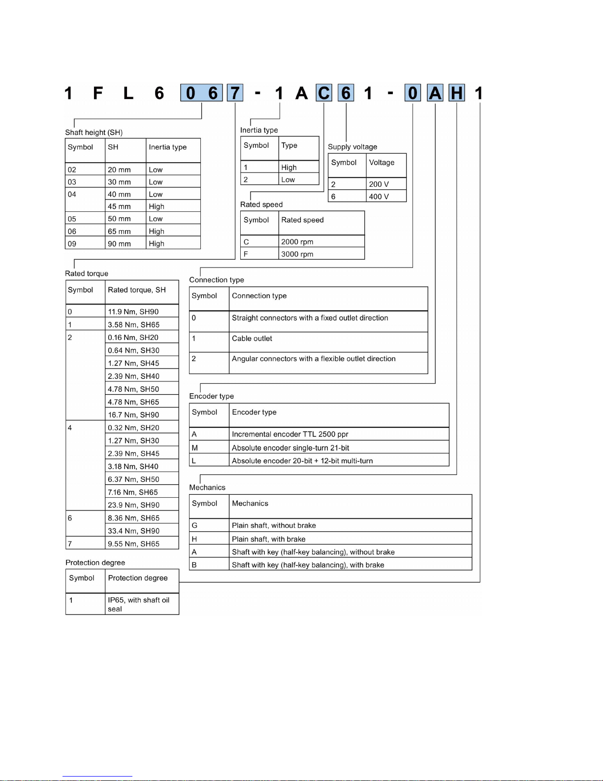
Getting Started
16 A5E37208904-003, 04/2017
Article number explanation
Page 17
Getting Started
A5E37208904-003, 04/2017
17
2.2
Device combination
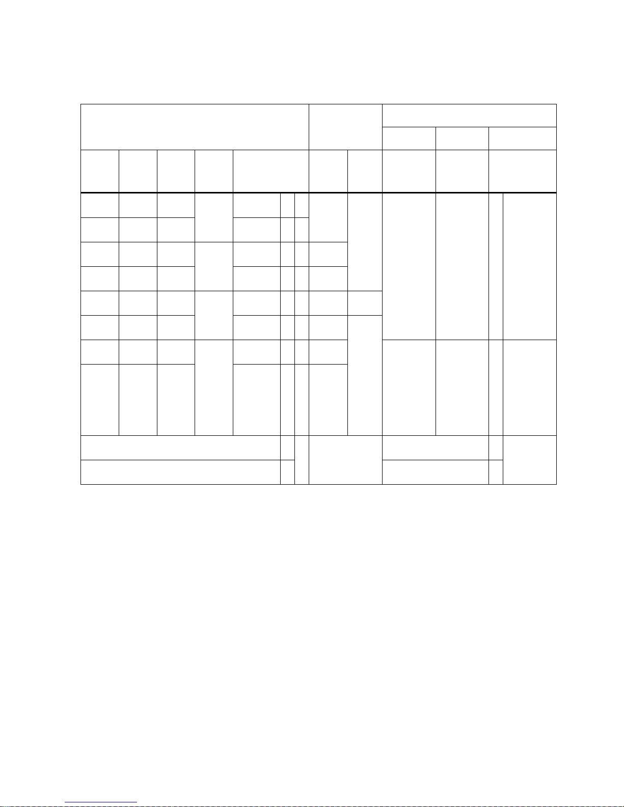
V90 PN 200 V servo system
SIMOTICS S-1FL6 low inertia servo motors
SINAMICS V90
PN 200 V servo
drives
MOTION-CONNECT 300 pre-assembled
cables
Power
cable
Brake cable
Encoder cable
Rated
torque
(Nm)
Rated
power
(kW)
Rated
speed
(rpm)
Shaft
height
(mm)
Article number
1FL60
Article
number
6SL321
0-5
Frame
size
Article
number
6FX3002-5
Article
number
6FX3002-5
Article number
6FX3002-2
0.16 0.05 3000 20 22-2AF21-1 ❑ ❑1 FB101UF0
FSB CK01-1AD0
(3 m)
CK01-1AF0
(5 m)
CK01-1BA0
(10 m)
CK01-1CA0
(20 m)
BK02-1AD0
(3 m)
BK02-1AF0
(5 m)
BK02-1BA0
(10 m)
BK02-1CA0
(20 m)
❑❑ 20-1AD0 (3
m)
20-1AF0 (5
m)
20-1BA0
(10 m)
20-1CA0
(20 m)
0.32 0.1 3000 24-2AF21-1 ❑ ❑
1
0.64 0.2 3000 30 32-2AF21-1 ❑ ❑1 FB10-
2UF0
1.27 0.4 3000 34-2AF21-1 ❑ ❑1 FB10-
4UF1
2.39 0.75 3000 40 42-2AF21-1 ❑ ❑1 FB10-
8UF0
FSC
3.18 1 3000 44-2AF21-1 ❑ ❑1 FB11-
0UF1
FSD
4.78 1.5 3000 50 52-2AF21-0 ❑ ❑1 FB11-
5UF0
CK31-1AD0
(3 m)
CK31-1AF0
(5 m)
CK31-1BA0
(10 m)
CK31-1CA0
(20 m)
BL02-1AD0
(3 m)
BL02-1AF0
(5 m)
BL02-1BA0
(10 m)
BL02-1CA0
(20 m)
❑❑ 10-1AD0 (3
m)
10-1AF0 (5
m)
10-1BA0
(10 m)
10-1CA0
(20 m)
6.37 2 3000 54-2AF21-0 ❑ ❑1 FB120UF0
Incremental encoder TTL 2500 ppr A Incremental encoder TTL
2500 ppr
CT
Absolute encoder single-turn 21-bit M Absolute encoder single-
turn 21-bit
D
B
Page 18
Getting Started
18 A5E37208904-003, 04/2017
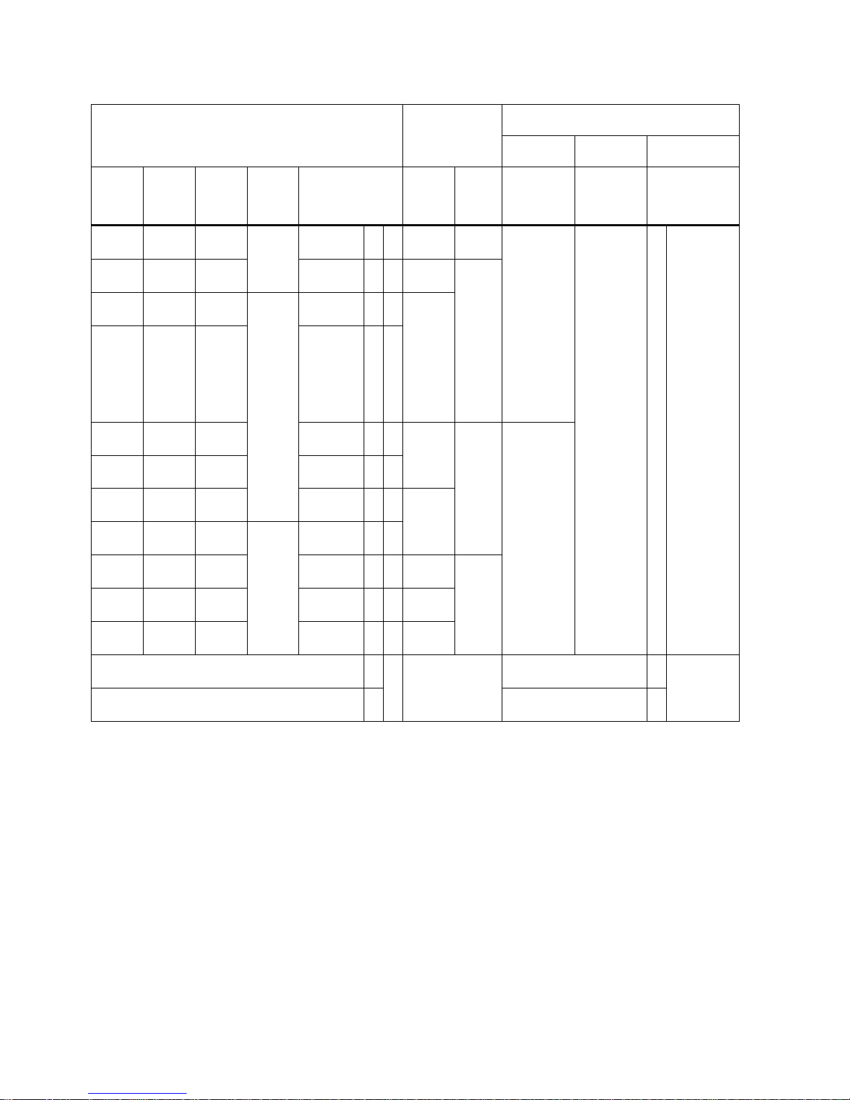
V90 PN 400 V servo system
SIMOTICS S-1FL6 high inertia servo motors with straight
connectors
SINAMICS V90
PN 400 V servo
drives
MOTION-CONNECT 300 pre-assembled
cables
Power
cable
Brake cable
Encoder cable
Rated
torque
(Nm)
Rated
power
(kW)
Rated
speed
(rpm)
Shaft
height
(mm)
Article number
1FL60
Article
number
6SL321
0-5
Frame
size
Article
number
6FX3002-5
Article
number
6FX3002-5
Article number
6FX3002-2
1.27 0.4 3000 45 42-1AF61-0 ❑ ❑1 FE10-
4UF0
FSAA CL01-1AD0
(3 m)
CL01-1AF0
(5 m)
CL01-1AH0
(7 m)
CL01-1BA0
(10 m)
CL01-1BF0
(15 m)
CL01-1CA0
(20 m)
BL02-1AD0
(3 m)
BL02-1AF0
(5 m)
BL02-1AH0
(7 m)
BL02-1BA0
(10 m)
BL02-1BF0
(15 m)
BL02-1CA0
(20 m)
❑❑ 10-1AD0 (3
m)
10-1AF0 (5
m)
10-1AH0 (7
m)
10-1BA0
(10 m)
10-1BF0
(15 m)
10-1CA0
(20 m)
2.39 0.75 3000 44-1AF61-0 ❑ ❑1 FE10-
8UF0
FSA
3.58 0.75 2000 65 61-
1AC61-0
❑ ❑1 FE11-
0UF0
4.78 1.0 2000 621AC61-0
❑ ❑
1
7.16 1.5 2000 64-
1AC61-0
❑ ❑1 FE11-
5UF0
FSB CL11-1AD0
(3 m)
CL11-1AF0
(5 m)
CL11-1AH0
(7 m)
CL11-1BA0
(10 m)
CL11-1BF0
(15 m)
CL11-1CA0
(20 m)
8.36 1.75 2000 66-
1AC61-0
❑ ❑
1
9.55 2.0 2000 67-
1AC61-0
❑ ❑1 FE12-
0UF0
11.9 2.5 2000 90 90-
1AC61-0
❑ ❑
1
16.7 3.5 2000 92-
1AC61-0
❑ ❑1 FE13-
5UF0
FSC
23.9 5.0 2000 94-
1AC61-0
❑ ❑1 FE15-
0UF0
33.4 7.0 2000 96-
1AC61-0
❑ ❑1 FE17-
0UF0
Incremental encoder TTL 2500 ppr A Incremental encoder TTL
2500 ppr
CT
Absolute encoder 20-bit + 12-bit multi-turn L Absolute encoder 20-bit +
12-bit multi-turn
D
B
Page 19
Getting Started
A5E37208904-003, 04/2017
19
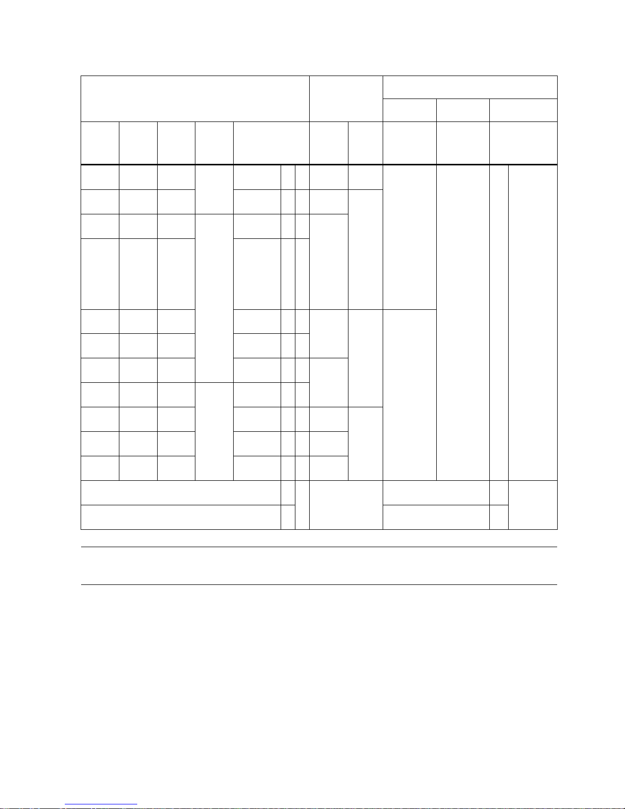
SIMOTICS S-1FL6 high inertia servo motors with angular
connectors
SINAMICS V90
PN 400 V servo
drives
MOTION-CONNECT 300 pre-assembled
cables
Power
cable
Brake cable
Encoder cable
Rated
torque
(Nm)
Rated
power
(kW)
Rated
speed
(rpm)
Shaft
height
(mm)
Article number
1FL60
Article
number
6SL321
0-5
Frame
size
Article
number
6FX3002-5
Article
number
6FX3002-5
Article number
6FX3002-2
1.27 0.4 3000 45 42-1AF61-2 ❑ ❑1 FE10-
4UF0
FSAA CL02-1AD0
(3 m)
CL02-1AF0
(5 m)
CL02-1AH0
(7 m)
CL02-1BA0
(10 m)
CL02-1BF0
(15 m)
CL02-1CA0
(20 m)
BL03-1AD0
(3 m)
BL03-1AF0
(5 m)
BL03-1AH0
(7 m)
BL03-1BA0
(10 m)
BL03-1BF0
(15 m)
BL03-1CA0
(20 m)
❑
❑
❑
❑
-1AD0 (3
m)
-1AF0 (5
m)
-1AH0 (7
m)
-1BA0 (10
m)
-1BF0 (15
m)
-1CA0 (20
m)
2.39 0.75 3000 44-1AF61-2 ❑ ❑1 FE10-
8UF0
FSA
3.58 0.75 2000 65 611AC61-2
❑ ❑1 FE11-
0UF0
4.78 1.0 2000 621AC61-2
❑ ❑
1
7.16 1.5 2000 64-
1AC61-2
❑ ❑1 FE11-
5UF0
FSB CL12-1AD0
(3 m)
CL12-1AF0
(5 m)
CL12-1AH0
(7 m)
CL12-1BA0
(10 m)
CL12-1BF0
(15 m)
CL12-1CA0
(20 m)
8.36 1.75 2000 66-
1AC61-2
❑ ❑
1
9.55 2.0 2000 67-
1AC61-2
❑ ❑1 FE12-
0UF0
11.9 2.5 2000 90 90-
1AC61-2
❑ ❑
1
16.7 3.5 2000 92-
1AC61-2
❑ ❑1 FE13-
5UF0
FSC
23.9 5.0 2000 94-
1AC61-2
❑ ❑1 FE15-
0UF0
33.4 7.0 2000 961AC61-2
❑ ❑1 FE17-
0UF0
Incremental encoder TTL 2500 ppr A Incremental encoder TTL
2500 ppr
CT
12
Absolute encoder 20-bit + 12-bit multi-turn L Absolute encoder 20-bit +
12-bit multi-turn
DB
10
Note
You can select a SINAMICS V90 PN servo drive for all the SIMOTICS S
-1FL6 servo motors whose rated power values are
equal to or smaller than that specified as matching with this servo drive in the table above.
Page 20
Getting Started
20 A5E37208904-003, 04/2017
2.3
Accessories
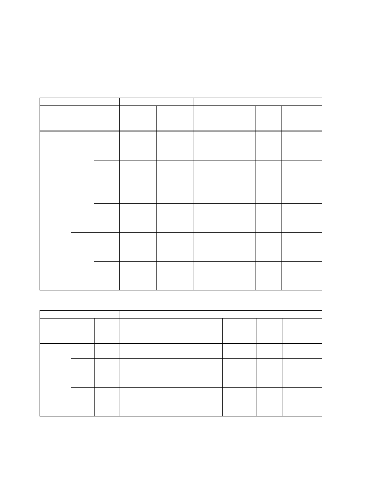
Fuse/Type-E combination motor controller
A fuse/type-E combination motor controller/circuit breaker can be used to protect the system. Integral solid state short circuit
protection does not provide branch circuit protection. Branch circuit protection must be provided in accordance with the
National Electrical Code and any additional local codes. Refer to the following table for the selection of fuses, type-E
combination motor controllers, and circuit breakers:
SINAMICS V90 PN 200 V variant
SINAMICS V90 PN
Recommended fuse
Type-E combination motor controller 1)
Power
supply
Frame
size
Rated
power
(kW)
CE-compliant
UL/cULcompliant
listed (JDDZ)
fuse
Rated
current
(A)
Rated voltage (VAC)
Rated
power
(hp)
Article number
1-phase,
200 VAC to
240 VAC
FSB 0.1 3NA3 801 (6
A)
6 A 2.8 to 4 230/240 1/3 3RV 2011-
1EA10
0.2 3NA3 801 (6
A)
6 A 2.8 to 4 230/240 1/3 3RV 2011-
1EA10
0.4 3NA3 803 (10
A)
10 A 5.5 to 8 230/240 1 3RV 2011-
1HA10
FSC 0.75 3NA3 805 (16
A)
20 A 9 to 12.5 230/240 2 3RV 2011-
1KA10
3-phase,
200 VAC to
240 VAC
FSB 0.1 3NA3 801 (6
A)
6 A 2.8 to 4 230/240 3/4 3RV 2011-
1EA10
0.2 3NA3 801 (6
A)
6 A 2.8 to 4 230/240 3/4 3RV 2011-
1EA10
0.4 3NA3 803 (10
A)
10 A 2.8 to 4 230/240 3/4 3RV 2011-
1EA10
FSC 0.75 3NA3 805 (16
A)
20 A 5.5 to 8 230/240 2 3RV 2011-
1HA10
FSD 1.0 3NA3 805 (16
A)
20 A 7 to 10 230/240 3 3RV 2011-
1JA10
1.5 3NA3 810 (25
A)
25 A 10 to 16 230/240 5 3RV 2011-
4AA10
2.0 3NA3 810 (25
A)
25 A 10 to 16 230/240 5 3RV 2011-
4AA10
1)
The above types for type-E combination motor controllers are listed in compliance with both CE and UL/cUL standards.
SINAMICS V90 PN 400 V variant
SINAMICS V90 PN
Recommended fuse type
Type-E combination motor controller 1)
Power
supply
Frame
size
Rated
power
(kW)
CE-compliant
UL/cULcompliant
listed (JDDZ)
fuse
Rated
current (A)
Rated voltage (VAC)
Rated
power
(hp)
Article number
3-phase,
380 VAC to
480 VAC
FSAA 0.4 3NA3 801-6
(6 A)
10 A 2.2 to 3.2 380/480 0.5 3RV 2021-
1DA10
FSA 0.75 3NA3 801-6
(6 A)
10 A 2.8 to 4 380/480 1 3RV 2021-
1EA10
1.0 3NA3 803-6
(10 A)
10 A 3.5 to 5 380/480 1.34 3RV 2021-
1FA10
FSB 1.5 3NA3 803-6
(10 A)
15 A 5.5 to 8 380/480 2 3RV 2021-
1HA10
2.0 3NA3 805-6
(16 A)
15 A 11 to 16 380/480 2.68 3RV 2021-
4AA10
Page 21
Getting Started
A5E37208904-003, 04/2017
21
SINAMICS V90 PN
Recommended fuse type
Type-E combination motor controller 1)
Power
supply
Frame
size
Rated
power
(kW)
CE-compliant
UL/cULcompliant
listed (JDDZ)
fuse
Rated
current (A)
Rated voltage (VAC)
Rated
power
(hp)
Article number
FSC 3.5 3NA3 807-6
(20 A)
25 A 14 to 20 380/480 4.7 3RV 2021-
4BA10
5.0 3NA3 807-6
(20 A)
25 A 14 to 20 380/480 6.7 3RV 2021-
4BA10
7.0 3NA3 810-6
(25 A)
25 A 20 to 25 380/480 9.4 3RV 2021-
4DA10
1)
The above types for Type-E combination motor controllers are listed in compliance with both CE and UL/cUL standards.
For more information about the accessories, refer to SINAMICS V90, SIMOTICS S-1FL6 Operating Instructions.
WARNING
Requirements for United States/Canadian installations (UL/cUL)
Suitable for use on a circuit capable of delivering not more than 65000 rms Symmetrical Amperes, 480 VAC maximum for
400 V variants of drives or 240 VAC maximum for 200 V variant drives, when protected by UL/cUL listed (JDDZ) fuse or
type E combination motor controller. For each frame size AA, A, B, C and D, use 75 °C copper wire only.
This equipment is capable of providing internal motor overload protection according to UL508C.
For Canadian (cUL) installations the drive mains supply must be fitted with any external recommended suppressor with the
following features:
• Surge-protective devices; device shall be a Listed Surge-protective device (Category code VZCA and VZCA7)
• Rated nominal voltage 480/277 VAC, 50/60 Hz, 3-phase
• Clamping voltage VPR = 2000 V, IN = 3kA min, MCOV = 508 VAC, SCCR = 65 kA
• Suitable for Type 2 SPD application
•
Clamping shall be provided between phases and also between phase and ground
Product maintenance
The components are subject to continuous further development within the scope of product maintenance (improvements to
robustness, discontinuations of components, etc).
These further developments are "spare parts-compatible" and do not change the article number.
In the scope of such spare parts-compatible further developments, connector positions are sometimes changed slightly. This
does not cause any problems with proper use of the components. Please take this fact into consideration in special
installation situations (e.g. allow sufficient clearance for the cable length).
Use of third-party products
This document contains recommendations relating to third-party products. Siemens accepts the fundamental suitability of
these third-party products.
You can use equivalent products from other manufacturers.
Siemens does not accept any warranty for the properties of third-party products.
Page 22

Getting Started
22 A5E37208904-003, 04/2017
2.4
Function list
Function
Description
Control mode
Basic positioner (EPOS) Positions axes in absolute/relative terms with a motor en-
coder
EPOS
Speed control (S) Flexibly controls motor speed and direction through
PROFINET communication port
S
Safe Torque Off (STO) Safely disconnects torque-generating motor power supply
to prevent an unintentional motor restart
EPOS, S
One-button auto tuning Estimates the machine characteristic and sets the closed
loop control parameters (speed loop gain, speed integral
compensation, filter if necessary, etc.) without any user
intervention
EPOS, S
Real-time auto tuning Estimates the machine characteristic and sets the closed
loop control parameters (speed loop gain, speed integral
compensation, filter if necessary, etc.) continuously in real
time without any user intervention
EPOS, S
Resonance suppression Suppresses the mechanical resonance, such as workpiece
vibration and base shake
EPOS, S
Low frequency vibration suppres-
sion
Suppresses the low frequency vibration in the machine
system
EPOS
Speed limit Limits motor speed through internal speed limit commands
(two groups)
EPOS, S
Torque limit Limits motor torque through internal torque limit commands
(two groups)
EPOS, S
Basic operator panel (BOP)
Displays servo status on a 6-digit 7-segment LED display
EPOS, S
External braking resistor - DCP, R1 An external braking resistor can be used when the internal
braking resistor is insufficient for regenerative energy
EPOS, S
Digital inputs/outputs (DIs/Dos) Control signals and status signals can be assigned to four
programmable digital inputs and two digital outputs
EPOS, S
PROFINET communication Supports communication between the SINAMICS V90 PN
servo drive and PLC with PROFINET communication protocol
EPOS, S
SINAMICS V-ASSISTANT You can perform parameter settings, test operation, ad-
justment and other operations with a PC
EPOS, S
Page 23
Getting Started
A5E37208904-003, 04/2017
23
2.5
Technical data
2.5.1
Technical data - servo drives
General technical data
Parameter
Description
24 VDC
power
supply
Voltage (V)
24 (-15% to +20%)
1)
Maximum current (A)
When using a motor without a brake: 1.5 A
When using a motor with a brake: 1.5 A + motor holding brake rated current (See
Section "Technical data - servo motors (Page 25)".)
Overload capability
300%
Control system
Servo control
Dynamic brake
Built-in
Protective functions Earthing fault protection, output short-circuit protection 2), overvolt-
age/undervoltage protection
3)
, I2t inverter,I2t motor, IGBT overtemperature pro-
tection 4)
Overvoltage criteria
Category III
Speed
control
mode
Speed control range
Internal speed command 1:5000
Torque limit
Set through a parameter
Environ-
mental
conditions
Surrounding air
temperature
Opera-
tion
0 °C to 45 °C: without power derating
45 °C to 55 °C: with power derating
Storage
-40 °C to +70 °C
Ambient humidi-
ty
Opera-
tion
< 90% (non-condensing)
Storage
90% (non-condensing)
Operating environment Indoors (without direct sunlight), free from corrosive gas, combustible gas, oil
gas, or dust
Altitude
≤ 1000 m (without power derating)
Degree of protection
IP 20
Degree of pollution
Class 2
Vibration Operation Shock Operational area II
Peak acceleration: 5 g, 30 ms and 15 g, 11 ms
Quantity of shocks: 3 per direction × 6 directions
Duration of shock: 1 s
Vibration
Operational area II
10 Hz to 58 Hz: 0.075 mm deflection
58 Hz to 200 Hz: 1 g vibration
Product packag-
ing
Vibration
2 Hz to 9 Hz: 3.5 mm deflection
9 Hz to 200 Hz: 1 g vibration
Quantity of cycles: 10 per axis
Sweep seed: 1 octave/min
Certifica-
tion
UL, CE, KC, C-Tick, EAC
1 )
When SINAMICS V90 PN works with a motor with a brake, the voltage tolerance of 24 VDC power supply must be -10%
to +10% to meet the voltage requirement of the brake.
2)
Integral solid state short circuit protection does not provide branch circuit protection. Branch circuit protection must be
provided in accordance with the National Electrical Code and any additional local codes.
3)
The V90 PN 200 V servo drive has an overvoltage threshold of 410 VDC and an undervoltage threshold of 150 VDC;
the V90 PN 400 V servo drive has an overvoltage threshold of 820 VDC and an undervoltage threshold of 320 VDC.
4)
SINAMICS V90 PN does not support motor overtemperature protection. Motor overtemperature is calculated by I2t and
protected by the output current from the drive.
Page 24
Getting Started
24 A5E37208904-003, 04/2017
Specific technical data
SINAMICS V90 PN 200V variant
Article No.
6SL3210-5FB...
10-1UF0
10-2UF0
10-4UF1
10-8UF0
11-0UF1
11-5UF0
12-0UF0
Frame size
FSB
FSB
FSB
FSC
FSD
FSD
FSD
Rated output current (A)
1.2
1.4
2.6
4.7
6.3
10.6
11.6
Max. output current (A)
3.6
4.2
7.8
14.1
18.9
31.8
34.8
Max. supported motor power (kW)
0.1
0.2
0.4
0.75
1.0
1.5
2.0
Power loss
1)
Main circuit (W)
8
15
33
48
65
105
113
Regenerative resistor
(W)
5 5 7 9 13 25 25
Control circuit (W)
16
16
16
16
16
18
18
Total (W)
29
36
56
73
94
148
156
Output frequency (Hz)
0 to 330
Power supply
Voltage/frequency FSB and FSC: single phase/three phase 200 VAC to 240 VAC, 50/60 Hz
FSD: three phase 200 VAC to 240 VAC, 50/60 Hz
Permissible voltage
fluctuation
-15% to +10%
Permissible frequency
fluctuation
-10% to +10%
Permissible supply con-
figuration
TN, TT, IT
Rated input
current (A)
1-phase
2.5
3.0
5.0
10.4 - -
-
3-phase 1.5 1.8 3.0 5.0 7.0 11.0 12.0
Power supply
capacity
(kVA)
1-phase
0.5
0.7
1.2
2.0 - -
-
3-phase 0.5 0.7 1.1 1.9 2.7 4.2 4.6
Inrush current (A)
8.0
Cooling method
Self-cooled
Fan-cooled
Mechanical
design
Outline dimensions (W x
H x D, mm)
50 x 170 x 170 80 x 170
x 195
95 x 170 x 195
Weight (kg)
1.25
1.95
2.3
2.4
1)
The values here are calculated at rated load.
SINAMICS V90 PN 400V variant
Article No.
6SL3210-5FE...
104UF0
108UF0
110UF0
115UF0
120UF0
135UF0
150UF0
170UF0
Frame size
FSAA
FSA
FSA
FSB
FSB
FSC
FSC
FSC
Rated output current (A)
1.2
2.1
3.0
5.3
7.8
11.0
12.6
13.2
Max. output current (A)
3.6
6.3
9.0
13.8
23.4
33.0
37.8
39.6
Max. supported motor power (kW)
0.4
0.75
1.0
1.75
2.5
3.5
5.0
7.0
Power loss
1)
Main circuit (W)
12
29
32
84
96
92
115
138
Regenerative resistor
(W)
17 57 57 131 131 339 339 339
Control circuit (W)
32
32
35
35
35
36
36
36
Total (W)
61
118
124
250
262
467
490
513
Output frequency (Hz) 0 to 330
Page 25

Getting Started
A5E37208904-003, 04/2017
25
Article No.
6SL3210-5FE...
104UF0
108UF0
110UF0
115UF0
120UF0
135UF0
150UF0
170UF0
Frame size
FSAA
FSA
FSA
FSB
FSB
FSC
FSC
FSC
Power supply
Voltage/frequency
Three phase 380 VAC to 480 VAC, 50/60 Hz
Permissible voltage fluc-
tuation
-15% to +10%
Permissible frequency
fluctuation
-10% to +10%
Permissible supply con-
figuration
TN, TT, IT
Rated input current (A)
1.5
2.6
3.8
6.6
9.8
13.8
15.8
16.5
Power supply capacity
(kVA)
1.7 3.0 4.3 7.6 11.1 15.7 18.0 18.9
Inrush current (A)
8.0
8.0
8.0
4.0
4.0
2.5
2.5
2.5
Cooling method
Self-cooled
Fan-cooled
Mechanical
design
Outline dimensions (W x
H x D, mm)
60 x
180 x
200
80 x 180 x 200 100 x 180 x 220 140 x 260 x 240
Weight (kg)
1.5
1.9
1.9
2.5
2.5
5.0
5.5
5.75
1)
The values here are calculated at rated load.
2.5.2
Technical data - servo motors
General technical data
Parameter
Description
Type of motor
Permanent-magnet synchronous motor
Cooling
Self-cooled
Relative humidity [RH]
90% (non-condensing at 30°C )
Installation altitude [m]
≤ 1000 (without power derating)
Thermal class
B
Vibration severity grade
A (according to IEC 60034-14)
Shock resistance [m/s2]
25 (continuous in axial direction); 50 (continuous in radial direction); 250
(in a short time of 6 ms)
Bearing lifetime [h]
> 20000
1)
Paint finish
Black
Protection degree of shaft
IP 65, with shaft oil seal
Type of construction
IM B5, IM V1, and IM V3
Positive rotation
Clockwise (default setting in servo drives)
Certification
CE, EAC
1)
This lifetime is only for refere
nce. When a motor keeps running at rated speed under rated load, replace its bearing after
20,000 to 30,000 hours of service time. Even if the time is not reached, the bearing must be replaced when unusual
noise, vibration, or faults are found.
Page 26
Getting Started
26 A5E37208904-003, 04/2017
Specific technical data
SIMOTICS S-1FL6, low inertia servo motor
Article No.
1FL60...
22
24
32
34
42
44
52
54
Rated power [kW]
0.05
0.1
0.2
0.4
0.75 1 1.5 2 Rated torque [Nm]
0.16
0.32
0.64
1.27
2.39
3.18
4.78
6.37
Maximum torque [Nm]
0.48
0.96
1.91
3.82
7.2
9.54
14.3
19.1
Rated speed [rpm]
3000
Maximum speed [rpm]
5000
Rated frequency [Hz]
200
Rated current [A] 1.2 1.2 1.4 2.6 4.7 6.3 10.6 11.6
Maximum current [A]
3.6
3.6
4.2
7.8
14.2
18.9
31.8
34.8
Moment of inertia [10-4
kgm2]
0.031 0.052 0.214 0.351 0.897 1.15 2.04 2.62
Moment of inertia (with
brake) [10-4 kgm2]
0.038 0.059 0.245 0.381 1.06 1.31 2.24 2.82
Recommended load to mo-
tor inertia ratio
Max. 30x Max. 20x Max. 15x
Operating temperature [°C] 1FL602❑, 1FL603❑ and 1FL604❑: 0 to 40 (without power derating)
1FL605❑: 0 to 30 (without power derating) 1)
Storage temperature [°C]
-20 to +65
Maximum noise level [dB]
60
Holding
brake
Rated voltage
(V)
24 ± 10%
Rated current
(A)
0.25 0.3 0.35 0.57
Holding brake
torque [Nm]
0.32 1.27 3.18 6.37
Maximum
brake opening
time [ms]
35 75 105 90
Maximum
brake closing
time [ms]
10 10 15 35
Maximum
number of
emergency
stops
2000
2)
Oil seal lifetime [h]
3000 to 5000
Encoder lifetime [h]
> 20000 3)
Protection degree of motor
body
IP 65
Protection degree of cable
end connector
IP20 -
Weight [kg]
With brake
0.70
0.86
1.48
1.92
3.68
4.20
6.76
8.00
Without brake
0.47
0.63
1.02
1.46
2.80
3.39
5.35
6.56
1)
When the surrounding temperature is between 30 °C and 40 °C, the 1FL605 motor will have a power derating of 10%.
2)
Restricted emergency stop operation is permissible. Up to 2000 braking operations for the motors of 0.05 kW to 1 kW,
and 200 braking operations for the motors of 1.5 kW to 2 kW can be executed with 300% rotor moment of inertia as external moment of inertia from a speed of 3000 rpm without the brake being subject to an inadmissible amount of wear.
3)
This lifetime is only for reference. When a motor keeps running at 80% rated value and the surrounding temperature is
30 °C, the encoder lifetime can be ensured.
Page 27
Getting Started
A5E37208904-003, 04/2017
27
Note
The data of rated torque, rated power, maximum torque in the above table allows a tolerance of 10%.
SIMOTICS S-1FL6, high inertia servo motor
Article No.
1FL60...
42
44
61
62
64
66
67
90
92
94
96
Rated power [kW]
0.40
0.75
0.75
1.00
1.50
1.75
2.00
2.5
3.5
5.0
7.0 1)
Rated torque [Nm]
1.27
2.39
3.58
4.78
7.16
8.36
9.55
11.9
16.7
23.9
33.4
Maximum torque [Nm]
3.8
7.2
10.7
14.3
21.5
25.1
28.7
35.7
50.0
70.0
90.0
Rated speed [rpm]
3000
2000
2000
Maximum speed [rpm]
4000
3000
3000
2500
2000
Rated frequency [Hz]
200
133
133
Rated current [A]
1.2
2.1
2.5
3.0
4.6
5.3
5.9
7.8
11.0
12.6
13.2
Maximum current [A]
3.6
6.3
7.5
9.0
13.8
15.9
17.7
23.4
33.0
36.9
35.6
Moment of inertia [10-4
kgm2]
2.7
5.2
8.0
15.3/1
1.7
2)
15.3
22.6
29.9
47.4
69.1
90.8
134.3
Moment of inertia (with
brake) [10-4 kgm2]
3.2
5.7
9.1
16.4/1
3.5 2)
16.4
23.7
31.0
56.3
77.9
99.7
143.2
Recommended load to
motor inertia ratio
Max. 10x
Max. 5x
Max. 5x
Operating temperature [°C]
0 to 40 (without power derating)
Storage temperature [°C]
-20 to +65
Maximum noise level [dB]
65
70
70
Holding
brake
Rated voltage
(V)
24 ± 10%
Rated current
(A)
0.88 1.44 1.88
Holding brake
torque [Nm]
3.5
12
30
Maximum
brake opening
time [ms]
60 180 220
Maximum
brake closing
time [ms]
45
60
115
Maximum
number of
emergency
stops
2000 3)
Oil seal lifetime [h]
5000
Encoder lifetime [h]
> 20000
4)
Degree of protection
IP65, with shaft oil seal
Weight of
incremental encoder
motor [kg]
With brake 2)
4.6/4.
8
6.4/6.
6
8.6/8.
8
11.3/1
0.1
11.3/1
1.5
14.0/1
4.2
16.6/1
6.8
21.3/2
1.5
25.7/2
5.9
30.3/3
0.5
39.1/3
9.3
Without brake
2)
3.3/3.4 5.1/5.2 5.6/5.7 8.3/7.0 8.3/8.4 11.0/1
1.1
13.6/1
3.7
15.3/1
5.4
19.7/1
9.8
24.3/2
4.4
33.2/3
3.3
Page 28

Getting Started
28 A5E37208904-003, 04/2017
Article No.
1FL60...
42
44
61
62
64
66
67
90
92
94
96
Weight of
absolute
encoder
motor [kg]
With brake 2) 4.4/4.5 6.2/6.3 8.3/8.4 11.0/9
.7
11.0/1
1.1
13.6/1
3.7
16.3/1
6.4
20.9/2
1.0
25.3/2
5.4
29.9/3
0.0
38.7/3
8.8
Without brake
2)
3.1/3.
2
4.9/5.
0
5.3/5.
4
8.0/6.
7
8.0/8.
1
10.7/1
0.8
13.3/1
3.4
14.8/1
4.9
19.3/1
9.4
23.9/2
4.0
32.7/3
2.8
1)
When the surrounding temperature is higher than 30 °C, the 1FL6096 motors with brake will have a power derating of
10%.
2)
The former value indicates the data for high inertia motors with straight connectors; the latter value indicates the data for
high inertia motors with angular connectors.
3)
Restricted emergency stop operation is permissible. Up to 2000 braking operations can be executed with 300% rotor
moment of inertia as external moment of inertia from a speed of 3000 rpm without the brake being subject to an inadmissible amount of wear.
4)
This lifetime is only for reference. When a motor keeps running at 80% rated value and the surrounding temperature is
30 °C, the encoder lifetime can be ensured.
Note
The data of rated torque, rated power, and maximum torque in th
e above table allows a tolerance of 10%.
Power derating
For deviating conditions (surrounding temperature > 40 °C or installation altitude > 1000 m above sea level) the permissible
torque/power must be determined from the following table. Surrounding temperatures and installation altitudes are rounded
off to 5 °C and 500 m respectively.
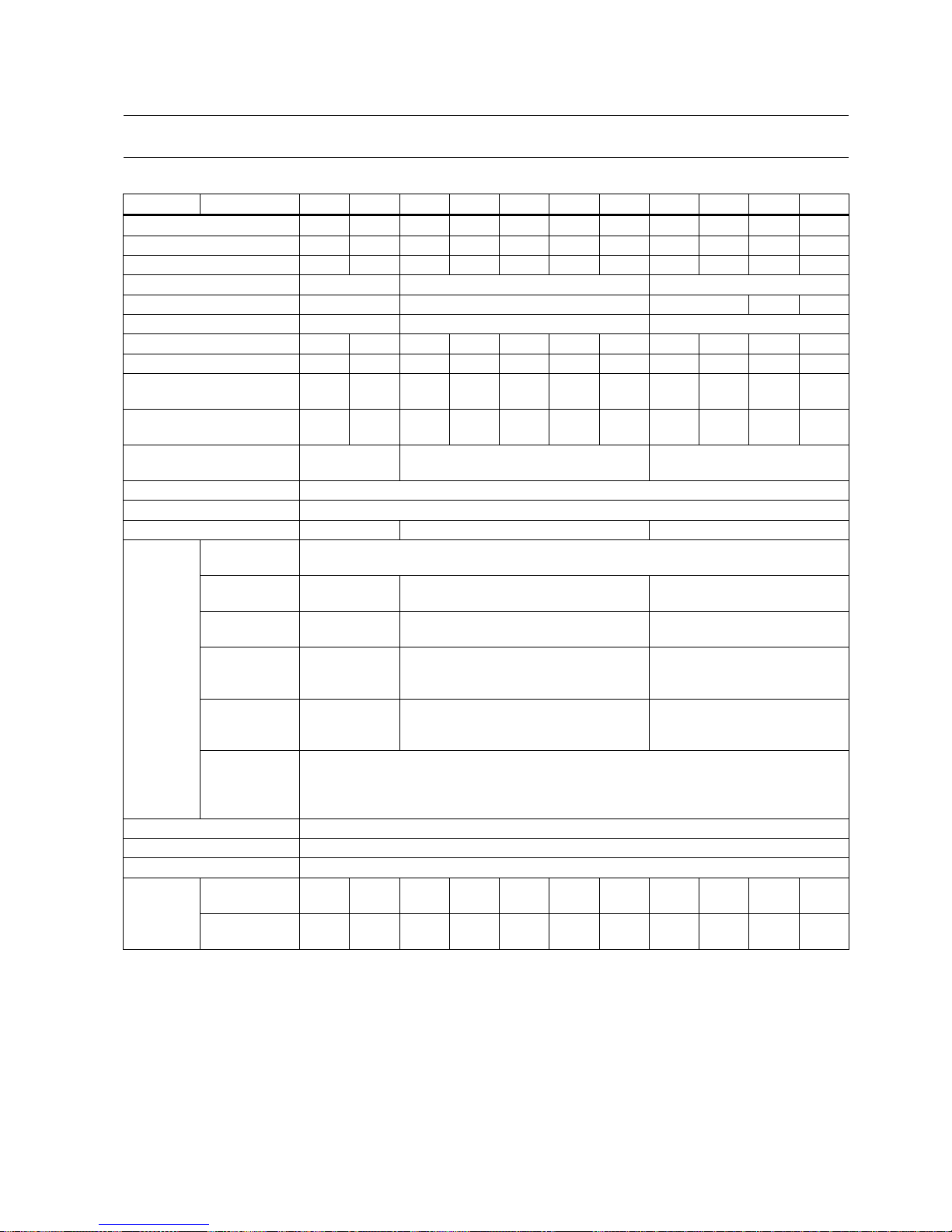
Power derating as a function of the installation altitude and ambient temperature
Installation altitude above sea
level (m)
Surrounding temperature in °C
< 30
30 to 40
45
50
55
1000
1.07
1.00
0.96
0.92
0.87
1500 1.04 0.97 0.93 0.89 0.84
2000
1.00
0.94
0.90
0.86
0.82
2500
0.96
0.90
0.86
0.83
0.78
3000
0.92
0.86
0.82
0.79
0.75
3500
0.88
0.82
0.79
0.75
0.71
4000
0.82
0.77
0.74
0.71
0.67
2.5.3
Address of CE-authorized manufacturer
The address of CE-authorized manufacturer is as follows:
Siemens AG
Digital Factory
Motion Control
Frauenauracher Straße 80
DE-91056 Erlangen
Germany
Page 29
Getting Started
A5E37208904-003, 04/2017
29
3
Mounting
3.1
Mounting the drive
Protection against the spread of fire
The device may be operated only in closed housings or in control cabinets with protective covers that are closed, and when
all of the protective devices are used. The installation of the device in a metal control cabinet or the protection with another
equivalent measure must prevent the spread of fire and emissions outside the control cabinet.
Protection against condensation or electrically conductive contamination
Protect the device, e.g. by installing it in a control cabinet with degree of protection IP54 according to IEC 60529 or
NEMA 12. Further measures may be necessary for particularly critical operating conditions.
If condensation or conductive pollution can be excluded at the installation site, a lower degree of control cabinet protection
may be permitted.
WARNING
Death or severe personal injury from harsh installation environment
A harsh installation environment will jeopardize personal safety and equipment. Therefore,
• Do not install the drive and the motor in an area subject to inflammables or combustibles, water or corrosion hazards.
• Do not install the drive and the motor in an area where it is likely to be exposed to constant vibrations or physical
shocks.
•
Do not keep the drive exposed to strong electro-magnetic interference.
CAUTION
Hot surface
During operation and for a short time after switching-off the drive, the surfaces of the drive can reach a high temperature.
Avoid coming into direct contact with the drive surface.
For mounting conditions, see Technical data - servo drives (Page 23).
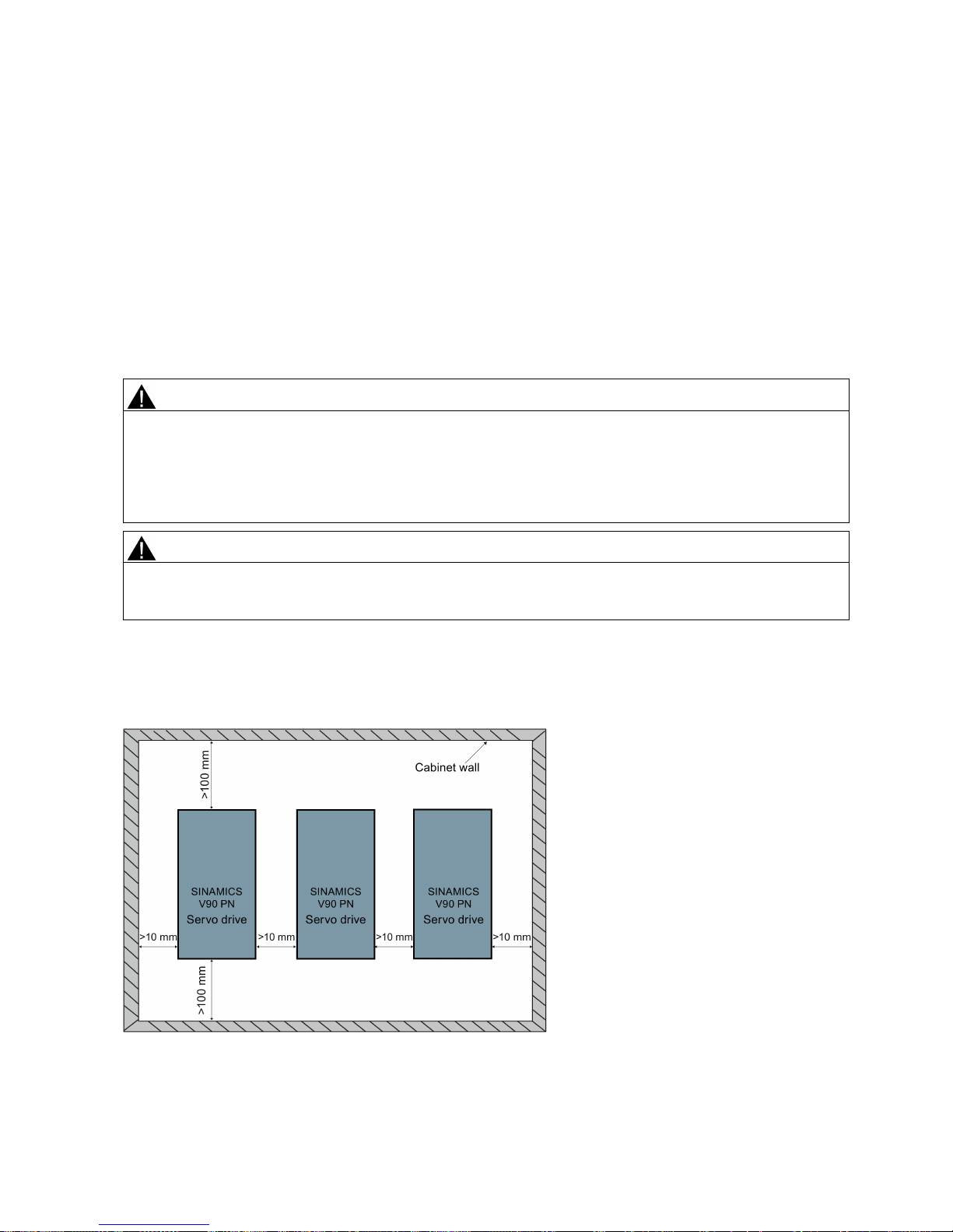
Mounting orientation and clearance
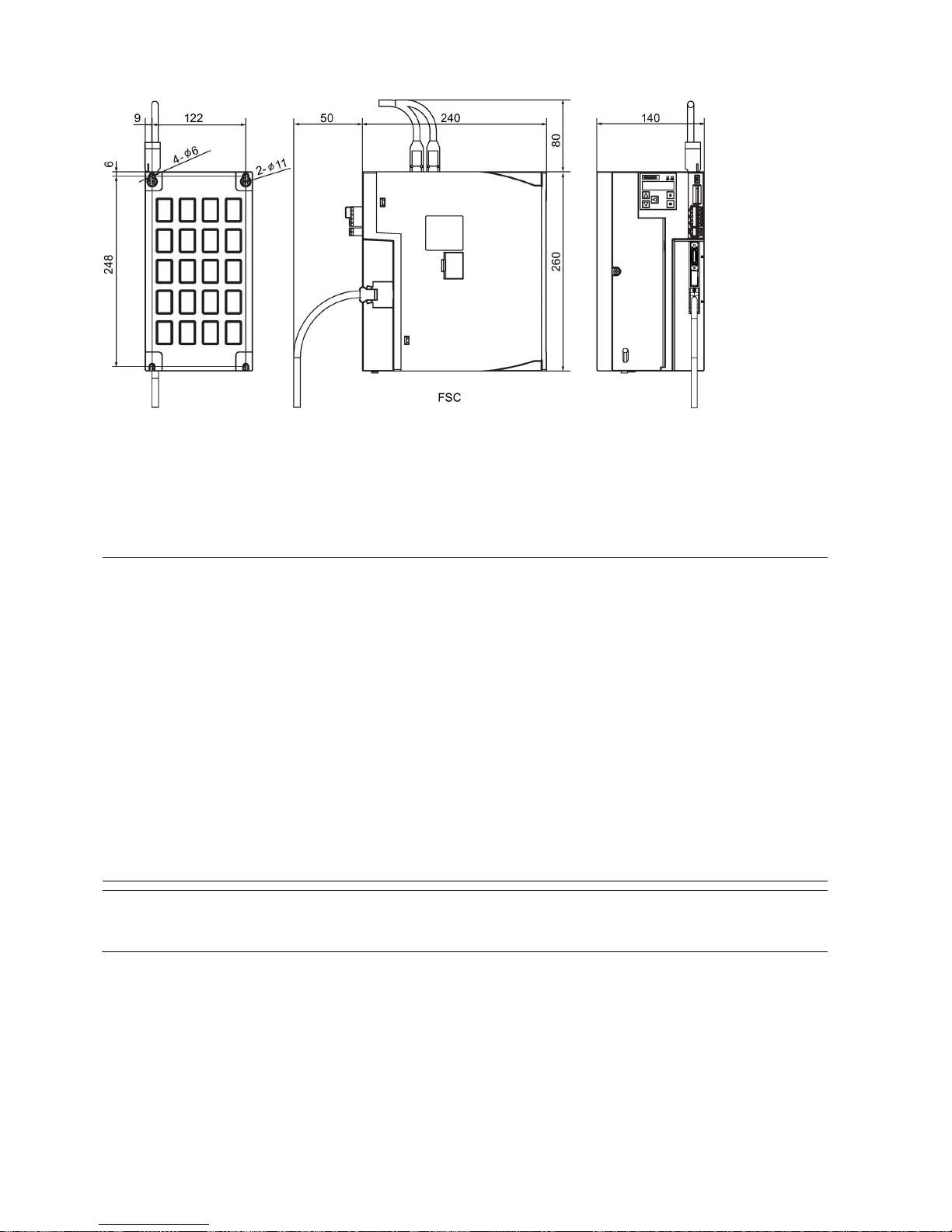
Mount the drive vertically in a shielded cabinet and observe the mounting clearances specified in the illustration below:
Page 30
Getting Started
30 A5E37208904-003, 04/2017
Note
The drive must be derated to 80% when the following conditions are satisfied:
•
The surrounding temperature is 0 °C to 45 °C, and the mounting clearance is less than 10
mm. In this case, the minimum
mounting clearance should not be less than 5 mm.
•
The surrounding temperature is 45 °C to 55 °C. In this case, the minimum mounting clearance should not be less than
20 mm.
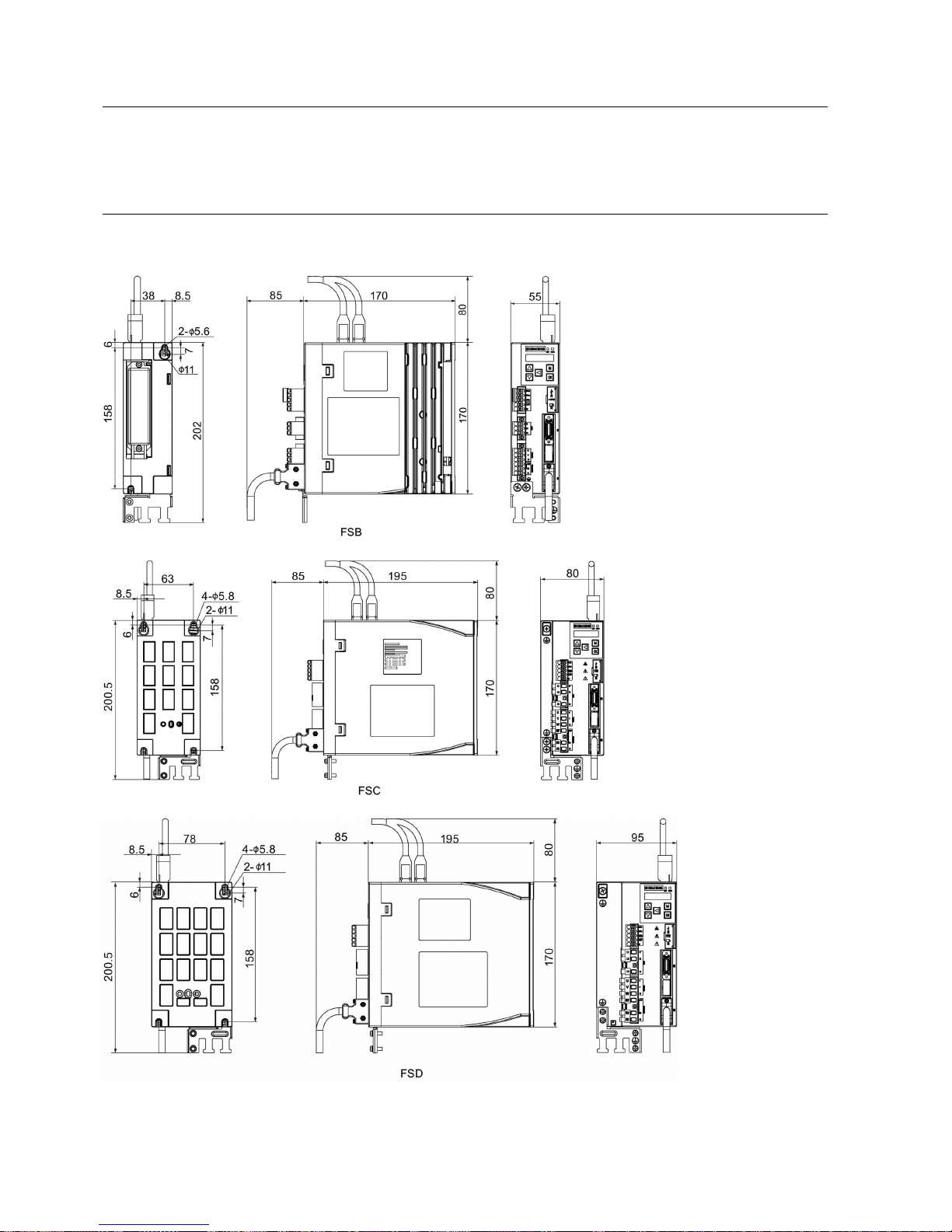
SINAMICS V90 PN 200V variant (unit: mm)
Page 31
Getting Started
A5E37208904-003, 04/2017
31
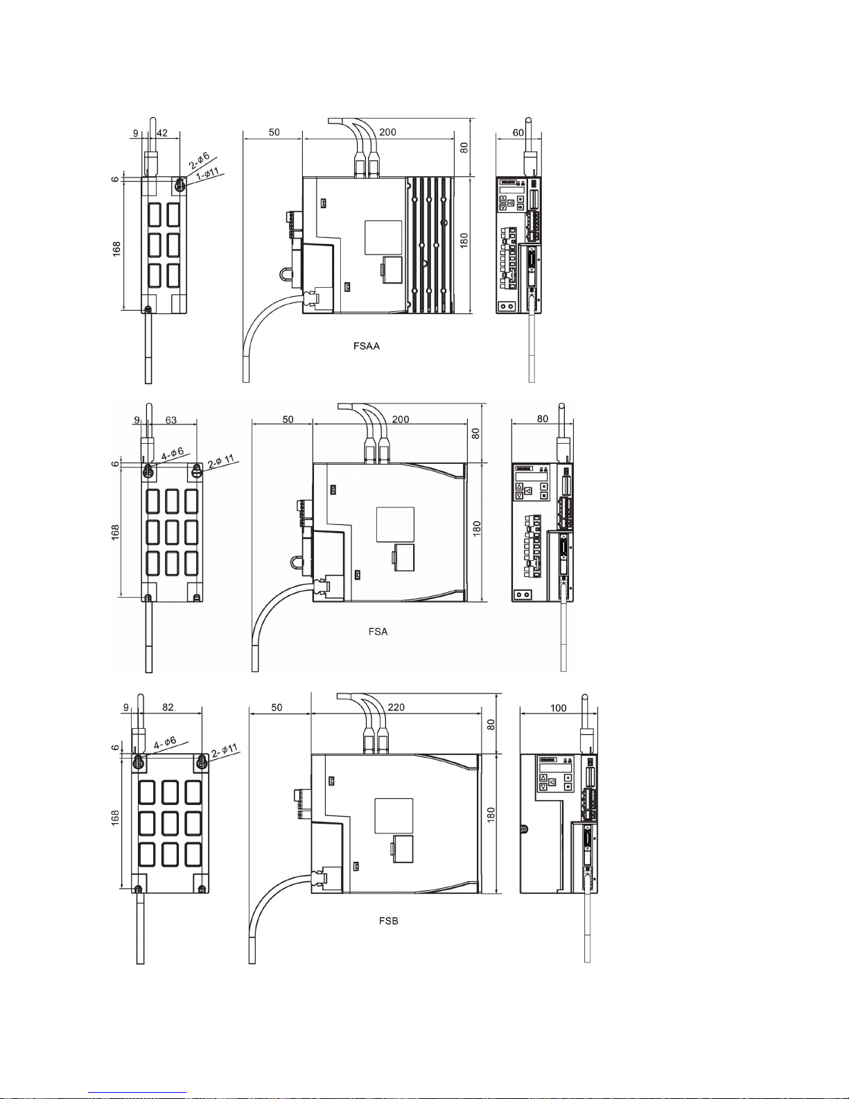
SINAMICS V90 PN 400V variant (unit: mm)
Page 32
Getting Started
32 A5E37208904-003, 04/2017
Mounting the drive
For V90 PN 200 V variant, use two M5 screws to mount the FSB drives and four M5 screws to mount the FSC, and FSD
drives.
For V90 PN 400 V variant, use two M5 screws to mount the FSAA drive and four M5 screws to mount the FSA, FSB, and
FSC drives.
The recommended tightening torque is 2.0 Nm.
Note
EMC instructions
•
To comply with the EMC standards, all cables connected with the SINAMICS V90 PN drive system must be shielded
cables, which include cables from the line supply to the line filter and from the line filter to the drive.
•
The SINAMICS V90 PN drives have been tested in accordance with the emission requirements of the category of C2
(domestic) environment. The conductive emissions and radiated emissions are in compliance with the standard of EN
55011 and reached Class A.
•
In a residential environment, this product can cause high-frequency interferences that may necessitate suppression
measures.
• For a radiated emission test, an external AC filter (between the mains supply and the drive) will be used to meet the EMC
requirement and the
drive will be installed inside the shielded metallic chamber, other parts of the motion control system
(including the PLC, DC power supply, motor) will be put inside the shielded chamber.
•
For a conductive emission test, an external AC filter (between the mains supply and the drive) will be used to meet the
EMC requirement.
• For the radiated emission and conductive emission test, the length of the line supply cable between the line filter and the
drive must be shorter than 1 m.
•
The harmonic current value of SINAMICS V90 PN drive exceeds the class A limit of IEC 61000-3-2, but the SINAMICS
V90 PN drive system installed within the Category C2 First Environment require supply authority acceptance for
connection to the public low-voltage power supply network. Please contact your local supply network provider.
Note
Screw tightening
Make sure you fix the screw to the terminal door of the drive after you have completed the installation work.
Page 33
Getting Started
A5E37208904-003, 04/2017
33
3.2
Mounting the motor
NOTICE
Damage to the encoder
Do not exert any shock at the shaft end; otherwise, the encoder may be damaged.
For mounting conditions, see Technical data - servo motors (Page 25).
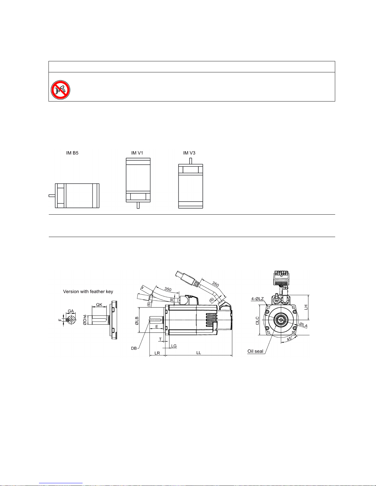
Mounting orientation
SIMOTICS S-1FL6 supports flange mounting only and three types of constructions, so it can be installed in three
orientations as shown in the following figure.
Note
When configuring the IM V3 type of construction, pay particular attention to the permissible axial force (weight force of the
drive elements) and the necessary degree of protection.
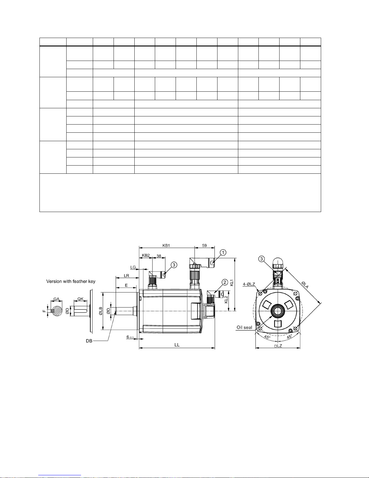
Motor dimensions (unit: mm)
Low inertia servo motor, shaft height: 20 mm, 30 mm, and 40 mm
Page 34
Getting Started
34 A5E37208904-003, 04/2017
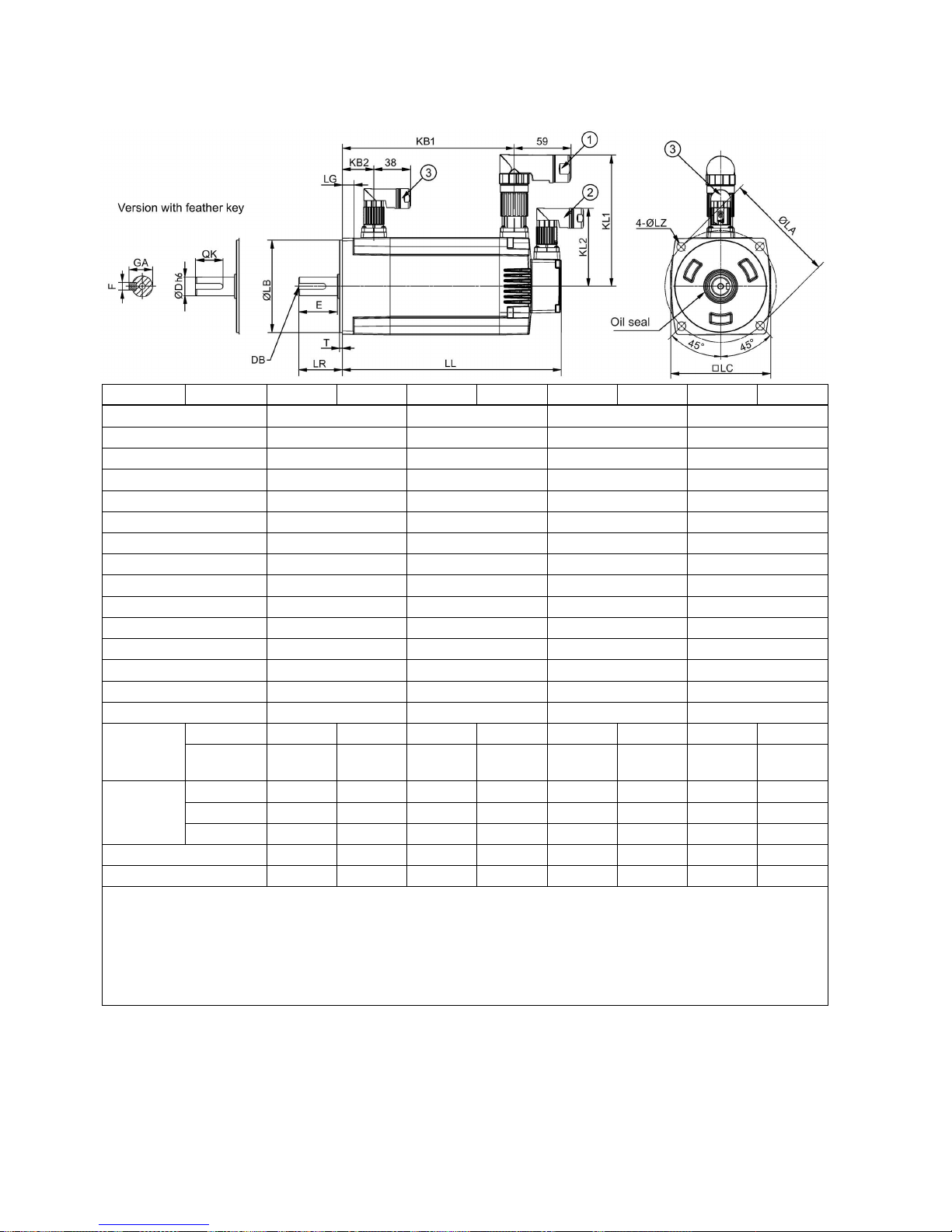
Low inertia servo motor, shaft height: 50 mm
Type
1FL60...
22
24
32
34
42
44
52
54
Shaft height
20
30
40
50
LC
40
60
80
100
LA
46
70
90
115
LZ
4.5
5.5 7 9
LB
30 - 0.02
50 - 0.03
70 - 0.03
95 - 0.03
LH
40
50
60
-
LR
25
31
35
45
T
2.5 - 0.2
3 - 0.2
3 - 0.3
3 - 0.3
LG 6 8 8 12
D
8 - 0.009 14 - 0.011 19 - 0.013 19 - 0.013
DB
M3 × 8
M4 × 15
M6 × 16
M6 × 16
E
22 26 30 40
QK
17.5
22.5
28
28
GA 9 16
21.5
21.5
F 3 5 6 6
Without
brake
LL
86
106
98
123
139
158.8
192
216
KB1
- - - - - - 143.5 167.5
With brake
LL
119
139
132.5
157.5
178.3
198.1
226
250
KB1 - - - - - -
177.5
201.5
KB2 - - - - - -
32.5
32.5
KL1 - - - - - -
135
135
KL2 - - - - - -
80
80
• ①−Power cable connector, ②−Incremental encoder cable connector, ③−Brake cable connector. These connectors
should be ordered separately. For more information about the order information of the connectors, see the SINAMICS
V90, SIMOTICS S-1FL6 Operating Instructions.
• For the low inertia motor with shaft-height of 50 mm, the boundary dimensions of encoder connector−
② and brake
connector−
③ are the same.
•
For the low inertia motor with shaft-height of 20 mm, only two screws are needed to mount the flange.
Page 35
Getting Started
A5E37208904-003, 04/2017
35
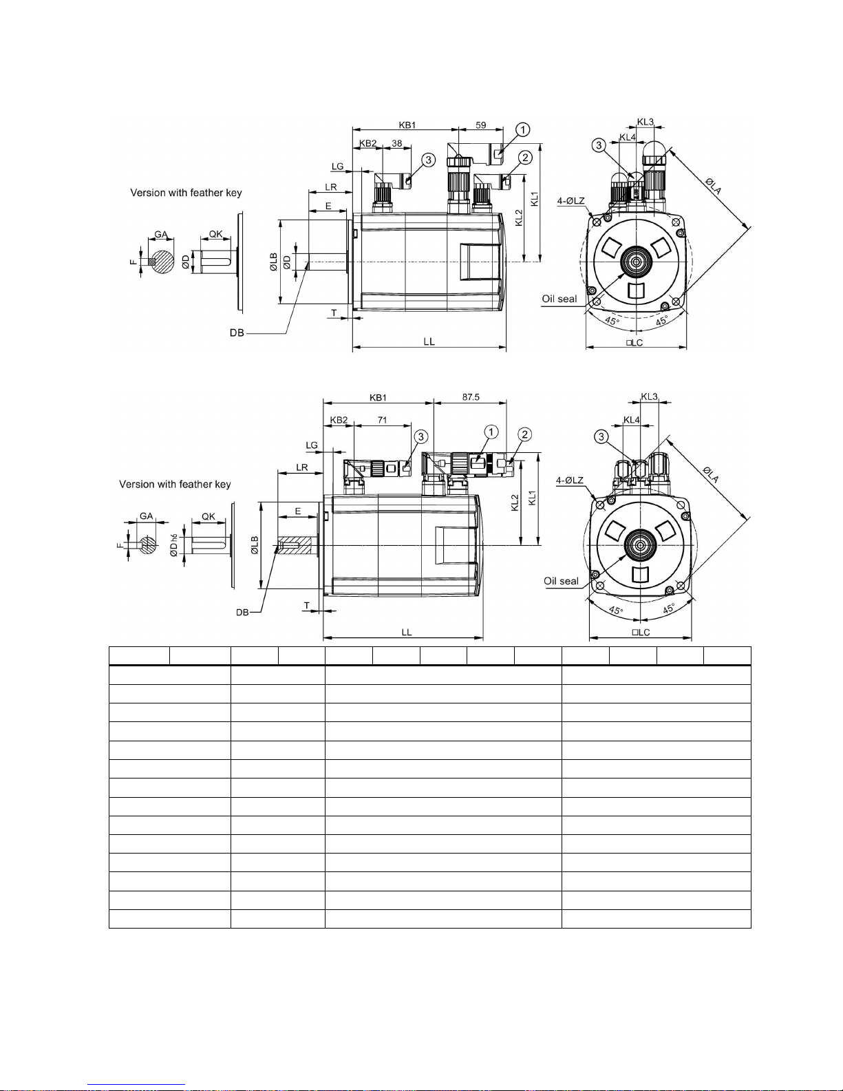
High inertia servo motor with straight connectors, with the incremental encoder
High inertia servo motor with angular connectors, with the incremental encoder
Type
1FL60...
42
44
61
62
64
66
67
90
92
94
96
Shaft height
45
65
90
LC
90
130
180
LA
100
145
200
LZ 7 9
13.5
LB
80 - 0.03
110 - 0.035
114.3 - 0.035
LR
35
58
80
T
4 - 0.3
6 - 0.3
3 - 0.3
LG
10
12
18
D
19 - 0.013
22 -0.013
35 - 0.016
DB
M6 x 16
M8 x 16
M12 x 25
E
30
50
75
QK
25
44
60
GA
21.5
25
38
F
6 - 0.03
8 - 0.036
10 - 0.036
Page 36
Getting Started
36 A5E37208904-003, 04/2017
Type
1FL60...
42
44
61
62
64
66
67
90
92
94
96
Without
brake
LL
154.5 201.5 148 181/16
4.5 1)
181 214 247 189.5 211.5 237.5 289.5
KB1
93.5
140.5
85.5
118.5
118.5
151.5
184.5
140
162
188
240
KB2 - -
-
With
brake
LL
201 248 202.5 235.5/
219 1)
235.5 268.5 301.5 255 281 307 359
KB1
140
187
140
173
173
206
239
206
232
258
310
KB2
31.5
39.5
44.5
With
straight
connectors
KL1
136
158
184
KL2
92
115
149
KL3
13
23
34
KL4
14 22 34
With
angular
connectors
KL1
96.2
117.5
143
KL2
84.6 108 141.1
KL3
13
23
34
KL4
14
22
34
• ①−Power cable connector, ②−Incremental encoder cable connector, ③−Brake cable connector. These connectors
should be ordered separately. For more information about the order information of the connectors, see the SINAMICS
V90, SIMOTICS S-1FL6 Operating Instructions.
• The boundary dimensions of encoder connector−
② and brake connector−③ are the same.
•
The shaft height 90 mm motor has two M8 screw holes for eyebolts.
1)
The former value indicates the dimension for high inertia motors with straight connectors; the latter value indicates the
dimension for high inertia motors with angular connectors.
High inertia servo motor with straight connectors, with the absolute encoder
Page 37
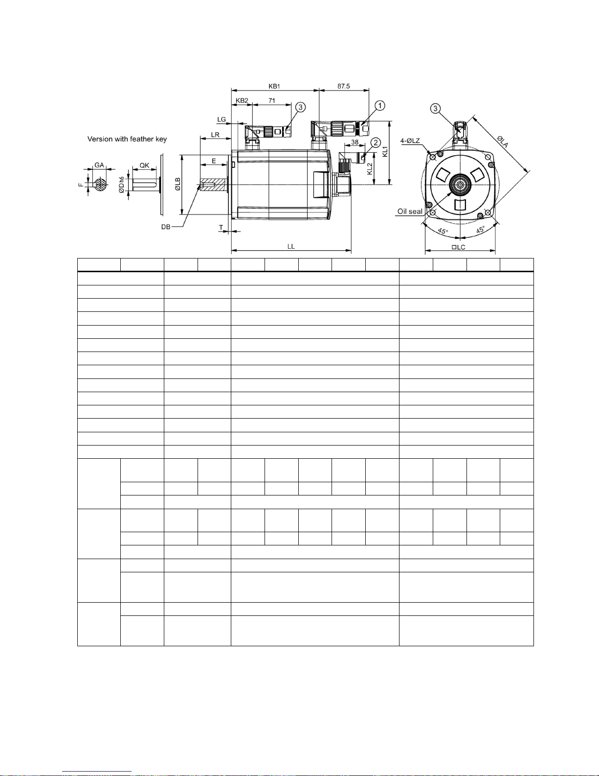
Getting Started
A5E37208904-003, 04/2017
37
High inertia servo motor with angular connectors, with the absolute encoder
Type
1FL60...
42
44
61
62
64
66
67
90
92
94
96
Shaft height
45
65
90
LC
90
130
180
LA
100
145
200
LZ 7 9
13.5
LB
80 - 0.03
110 - 0.035
114.3 - 0.035
LR
35
58
80
T
4 - 0.3
6 - 0.3
3 - 0.3
LG
10
12
18 D 19 - 0.013
22 - 0.013
35 - 0.016
DB
M6 x 16
M8 x 16
M12 x 25
E
30
50
75
QK
25
44
60
GA
21.5
25
38
F
6 - 0.03
8 - 0.036
10 - 0.036
Without
brake
LL
157 204 151 184/16
7.5 1)
184 217 250 197 223 249 301
KB1
100
147
92
125
125
158
191
135
161
187
239
KB2
- - -
With
brake
LL
203.5 250.5 205.5 238.5/
222 1)
238.5 271.5 304.5 263 289 315 367
KB1
147
194
147
180
180
213
246
201
227
253
305
KB2
31.5
39.5
44.5
With
straight
connectors
KL1
136
158
184
KL2
60 60 60
With
angular
connectors
KL1
96.2
117.5
143
KL2
60 60 60
Page 38
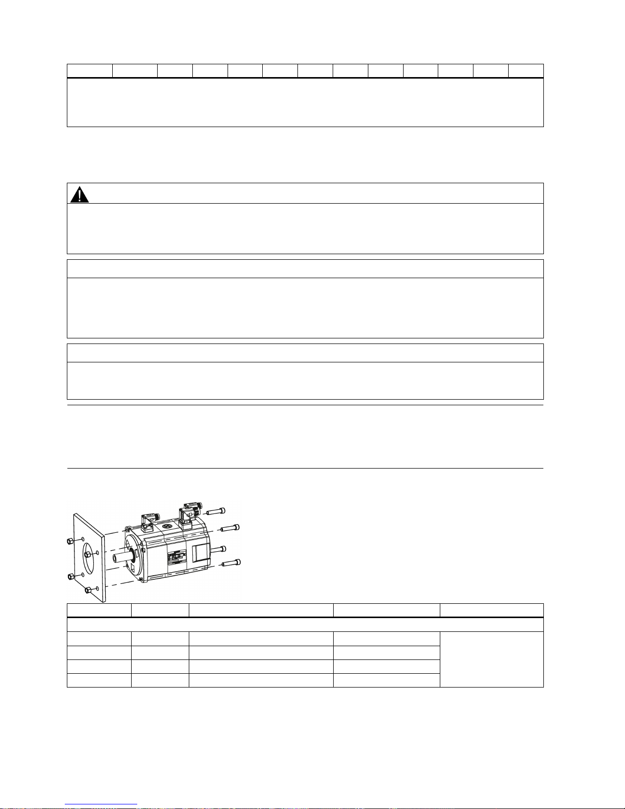
Getting Started
38 A5E37208904-003, 04/2017
Type
1FL60...
42
44
61
62
64
66
67
90
92
94
96
• ①-Power cable connector, ②−Absolute encoder cable connector, ③−Brake cable connector. These connectors
should be ordered separately. For more information about the order information of the connectors, see the SINAMICS
V90, SIMOTICS S-1FL6 Operating Instructions.
•
The shaft height 90 mm motor has two M8 screw holes for eyebolts.
1)
The former value indicates the dimension for high inertia motors with straight connectors; the latter value indicates the
dimension for high inertia motors with angular connectors.
Mounting the motor
WARNING
Personal injury and material damage
Some motors, especially the 1FL609❑ are heavy. The excessive weight of the motor should be considered and any
necessary assistance required for mounting should be sought.
Otherwise, the motor can fall down during mounting. This can result in serious personal injury or material damage.
NOTICE
Damage to the motor
If the liquid enters the motor, the motor may be damaged
During motor installation or operation, make sure that no liquid (water, oil, etc.) can penetrate into the motor. Besides,
when installing the motor horizontally, make sure that the cable outlet faces downward to protect the motor from ingress of
oil or water.
NOTICE
Magnetic interference to the absolute encoder from the magnetic field
To avoid magnetic interference to the absolute encoder, keep the servo motor with an absolute encoder at least 15 mm
away from the devices that produce a magnetic field stronger than 10 mT.
Note
Using the eyebolts
The 1FL609❑ motor (90 mm shaft height) has two M8 screw holes for screwing in two eyebolts. Lift the 1FL609❑ motor only
at the eyebolts.
Eyebolts that have been screwed in must be either tightened or removed after mounting.
Install the motor onto a steel flange with four screws as shown in the following figure:
Motor
Screw
Recommended flange size
Tightening torque
Flange material
Low inertia motors
1FL602❑
2 x M4
120 x 100 x 40 (mm)
2.4 Nm
Steel
1FL603❑
4 x M5
120 x 100 x 40 (mm)
4.7 Nm
1FL604❑
4 x M6
120 x 100 x 40 (mm)
8 Nm
1FL605❑
4 x M8
120 x 100 x 40 (mm)
20 Nm
Page 39
Getting Started
A5E37208904-003, 04/2017
39
Motor
Screw
Recommended flange size
Tightening torque
Flange material
High inertia motors
1FL604❑
4 x M6
270 x 270 x 10 (mm)
8 Nm
Steel
1FL606❑
4 x M8
390 x 390 x 15 (mm)
20 Nm
1FL609❑
4 x M12
420 x 420 x 20 (mm)
85 Nm
Motor heating conditions
The rated motor specifications are continuous allowable values at a surrounding air temperature of 40 °C when the motor is
installed with a steel flange. When the motor is mounted on a small surface, the motor temperature may rise considerably
because of the limited heat radiating abilities of the surface. Make sure you use a suitable flange according to Siemens
recommended flange sizes.
Note
The actual temperature ris
e depends on how the flange (motor mounting section) is fixed on the installation surface, what
material is used for the motor mounting section, and motor speed. Always check the actual motor temperature.
Page 40
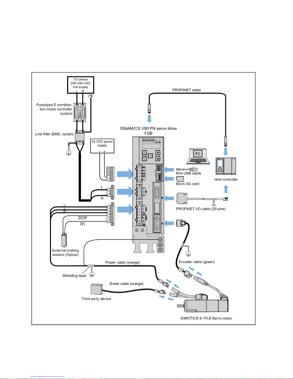
Getting Started
40 A5E37208904-003, 04/2017
4
Connecting
4.1
System connection
The following illustrations show the examples of the SINAMICS V90 PN servo system connection.
Connection diagram for FSB on the single phase power network:
Page 41
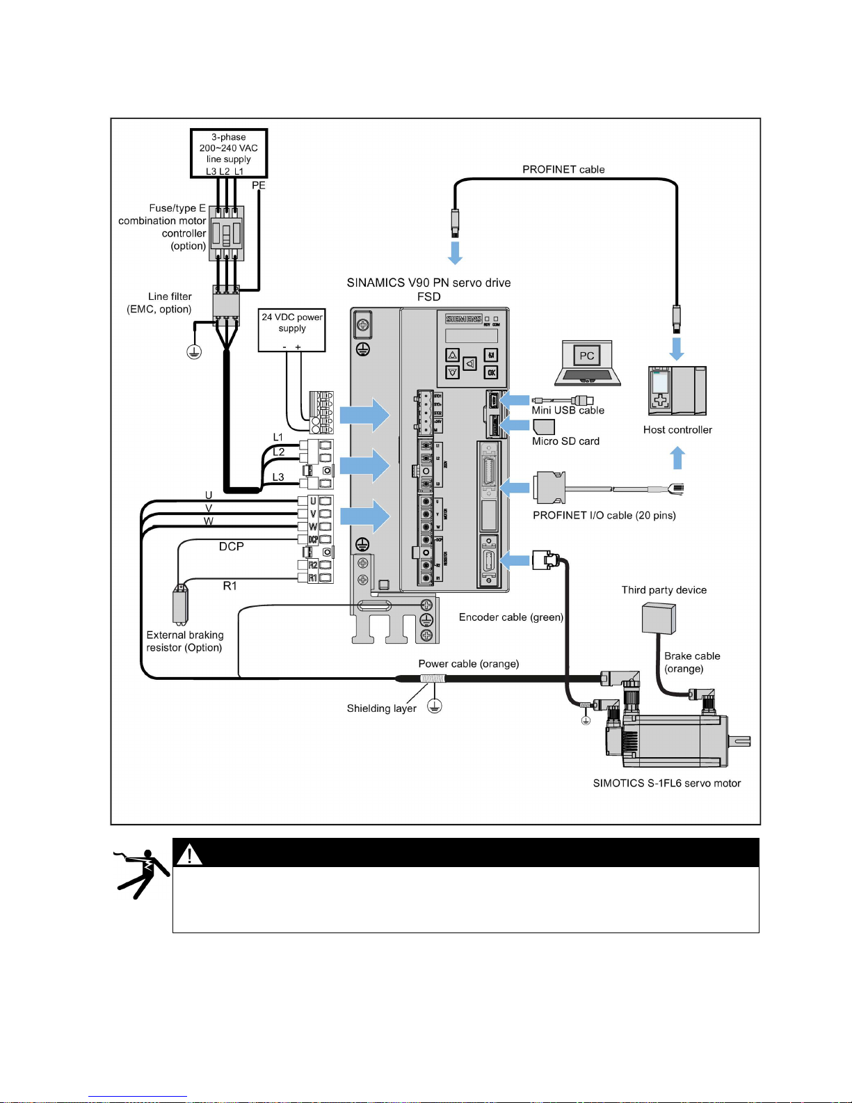
Getting Started
A5E37208904-003, 04/2017
41
Connection diagram for FSD on the three phase power network:
DANGER
Danger to life when PE connectors are touched
When the equipment is working, hazardous touch current can be present at the PE connectors; if touched, this
can result in death or severe personal injury.
•
Do not touch the PE connector during operation or within a certain period since power disconnection.
Page 42
Getting Started
42 A5E37208904-003, 04/2017
WARNING
Personal injury and damage to property from improper connections
Improper connections have high risks of electrical shock and short circuit, which will jeopardize personal safety
and equipment.
• The drive must be dir
ectly connected with the motor. It is not permissible to connect a capacitor, inductor or
filter between them.
• The line supply voltage must be within the allowable range (refer to the drive rating plate). Never connect
the line supply cable to the motor terminals U, V, W or connect the motor power cable to the line input
terminals L1, L2, L3.
• Never wire up the U, V, W terminals in an interchanged phase sequence.
• If the CE marking for cables is mandatory in some cases, the motor power cable, line supply cable and
brake cable used must all be shielded cables.
• For terminal connection, make sure that the clearances in air between non-insulated live parts are at least
5.5 mm.
• Route signal cables and power cables separately in different cable conduits. The signal cables shall be at
least 10 cm away from the power cables.
• Cables connected may not come into contact with rotating mechanical parts.
CAUTION
Personal injury and damage to property from inadequate protection
Inadequate protection may cause minor personal injury or damage to property.
• Route a second PE conductor with the cross section of the supply system lead in parallel to the protective earth via
separate terminals or use a copper protective earth conductor with a cross section of 10 mm
2
.
• Terminals for equipotential bondings that exist in addition to terminals for PE conductors must not be used for looping-
through the PE conductors.
•
To ensure protective separation, an isolating transformer must be used for the 220 VAC/380 VAC line supply system.
NOTICE
Important wiring information
In order to meet
EMC
requirements, all cables must be shielded cables.
The cable shields of shielded twisted-
pair cables should be connected to the shielding plate or the cable clamp of the servo
drive.
NOTICE
Drive damage caused by short-circuiting between the shielding wire and the unused pin on the PROFINET I/O connector
The shielding wire may inadvertently be short-circuited to the unused pin on the to-be-assembled PROFINET I/O
connector. This can cause damage to the drive.
Exercise caution when connecting the shielding cable to the PROFINET I/O connector.
For more information about the assembly method of the connector, see Section "Assembly of cable terminals on the drive
side" in the SINAMICS V90, SIMOTICS S-1FL6 Operating Instructions.
Note
Low Voltage Directive complied
Our products comply
with EN61800-5-1: 2007 standards and Low Voltage Directive (Low Voltage Directive 2006/95/EC).
Note
For low inertia motors of shaft heights 20 mm, 30 mm and 40 mm, the encoder cable connectors may only be accessible to
electrically skilled personnel.
Note
The mini
-USB interface of the SINAMICS V90 PN is used for fast commissioning and diagnostics with SINAMICS V-
ASSISTANT installed in the PC. Do not use it for long monitoring.
Page 43
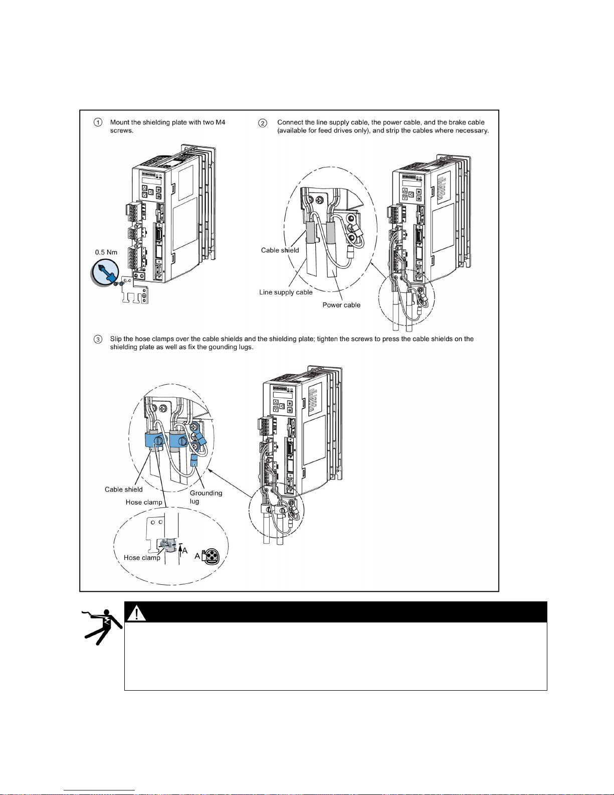
Getting Started
A5E37208904-003, 04/2017
43
Connecting the cable shields with the shielding plate
To achieve EMC-compliant installation of the drive, use the shielding plate that is shipped with the drive to connect the cable
shields. See the following example for steps of connecting cable shields with the shielding plate:
DANGER
Death or severe personal injury from electrical shock
The earth leakage current for the drive can be greater than AC 3.5 mA, which may cause death or severe
personal injury due to electrical shock.
A fixed earth connection is required to eliminate the dangerous leakage current. In addition, the minimum size
of the protective earth conductor shall comply with the local safety regulations for high leakage current
equipment.
Page 44
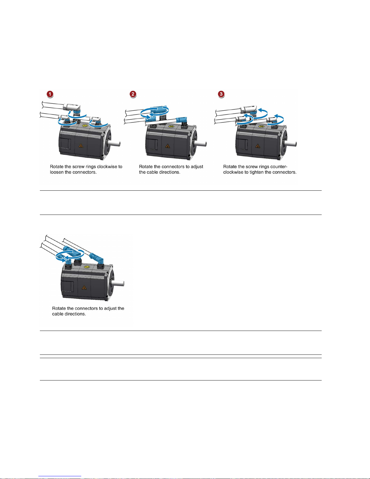
Getting Started
44 A5E37208904-003, 04/2017
Adjusting cable directions from the motor side
For some low inertia motors and all high inertia motors, you can adjust the direction of the power cable, encoder cable, or
brake cable from the motor side to facilitate cable connection.
The following illustrations take high inertia motors with the incremental encoder for example to show how to adjust the cable
directions.
Low inertia motors with a shaft height of 50 mm and high inertia motors with straight connectors
Note
Rotating the connectors
You can rotate all the three motor
-side connectors only within 360°.
High inertia motors with angular connectors
Note
Rotating the connectors
Yo
u can rotate all the three motor-side connectors only within 310°.
Note
For an absolute encoder cable on a high inertia motor with angular connectors, adjust its direction just the same as you
adjust the cable directions on a high inertia motor with str
aight connectors mentioned above.
Page 45
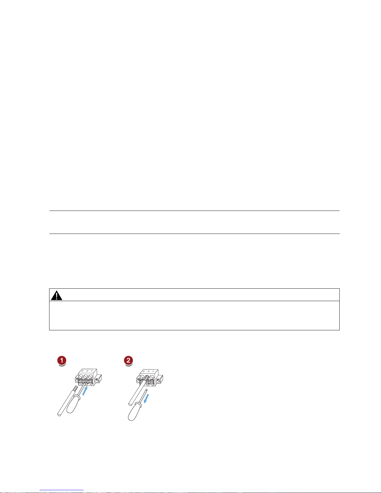
Getting Started
A5E37208904-003, 04/2017
45
4.2
Main circuit wiring
4.2.1
Line supply - L1, L2, L3
SINAMICS V90 PN 200 V variant
Recommended minimum cable cross-section:
When used on the single phase power network:
FSB (0.1 kW to 0.2 kW): 0.33 mm2
FSB (0.4 kW): 0.52 mm2
FSC: 1.31 mm2
When used on the three phase power network:
FSB: 0.33 mm2
FSC: 0.52 mm2
FSD (1 kW): 0.82 mm2
FSD (1.5 kW to 2 kW): 2.08 mm2
SINAMICS V90 PN 400 V variant
Recommended minimum cable cross-section:
FSAA and FSA: 1.5 mm
2
FSB and FSC: 2.5 mm2
Note
For 200 V variant, when using the FSB and FSC on the single phase power network, you can connect the power supply to
any two connectors of L1, L2, and L3.
Assembling the line supply cable terminals
The procedure of assembling a line supply cable terminal is the same as that for a power cable terminal on the drive side.
For more information, see the SINAMICS V90, SIMOTICS S-1FL6 Operating Instructions.
Attaching the line supply cable
CAUTION
Risk of injury due to improper cable connection
When attaching the line supply cable to a line supply connector that has not been fixed on the drive, you can injure your
fingers.
•
Make sure you first fix the line supply connector on the drive, and then attach the cable to the connector.
200 V variant
● For FSB
Page 46
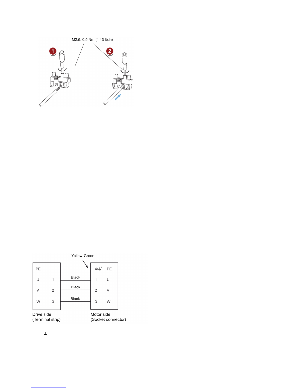
Getting Started
46 A5E37208904-003, 04/2017
● For FSC and FSD
400 V variant
● For FSAA and FSA
You can attach the line supply cable with the same method for 200 V variant drives of frame sizes FSC and FSD.
● For FSB and FSC
The FSB and FSC servo drives are equipped with barrier terminals for line supply connection. You can fix the line supply
cable on the servo drives by using the M4 screws with a tightening torque of 2.25 Nm (19.91 lb.in).
4.2.2
Motor power - U, V, W
Motor output - drive side
SINAMICS V90 PN 200 V variant
Recommended minimum cable cross-section:
FSB: 0.75 mm2
FSC and FSD (1 kW): 0.75 mm2
FSD (1.5 kW to 2 kW): 2.5 mm2
SINAMICS V90 PN 400 V variant
Recommended minimum cable cross-section:
FSAA and FSA: 1.5 mm2
FSB and FSC: 2.5 mm2
Wiring
*
4: high inertia motors with straight connectors and all low inertia motors
: high inertia motors with angular connectors
Page 47
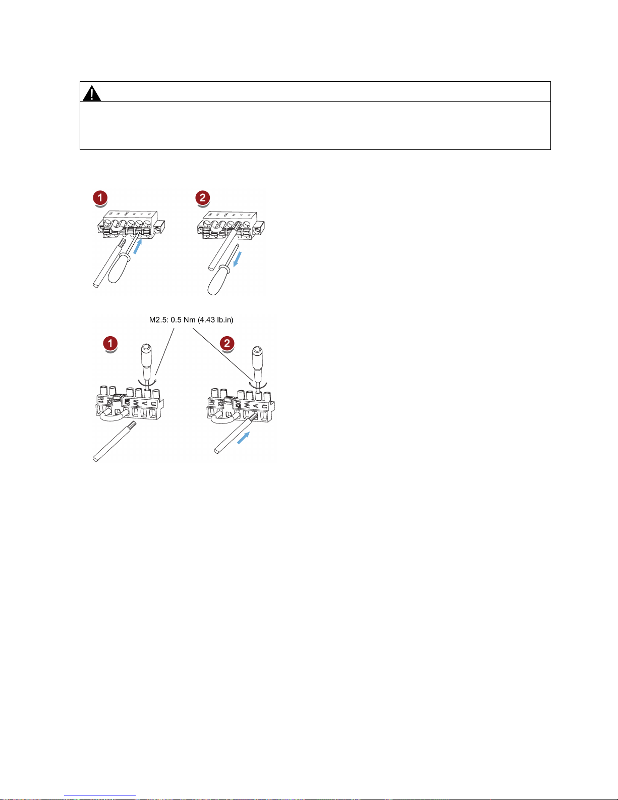
Getting Started
A5E37208904-003, 04/2017
47
Attaching the motor power cable
CAUTION
Risk of injury due to improper cable connection
When attaching the motor power cable to a
motor power connector that has not been fixed on the drive, you can injure your
fingers.
•
Make sure you first fix the motor power connector on the drive, and then attach the cable to the connector.
200 V variant
● For FSB
● For FSC and FSD
400 V variant
● For FSAA and FSA
You can attach the motor power cable with the same method for 200 V variant drives of frame sizes FSC and FSD.
● For FSB and FSC
The FSB and FSC servo drives are equipped with barrier terminals for motor power connection. You can fix the motor
power cable on the servo drives by using the M4 screws with a tightening torque of 2.25 Nm (19.91 lb.in).
Page 48
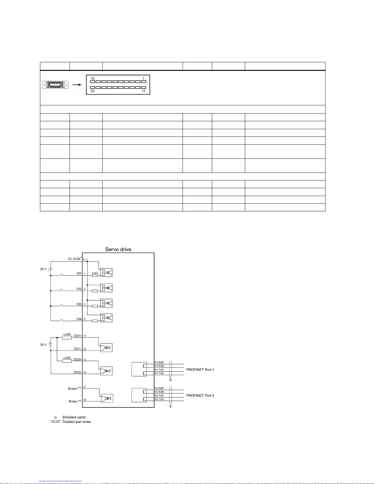
Getting Started
48 A5E37208904-003, 04/2017
4.3
Control/Status interface - X8
4.3.1
Interface definition
Pin
Signal
Description
Pin
Signal
Description
Type: 20-pin MDR socket
Digital inputs/outputs
1
DI1
Digital input 1
11
DO1+
Digital output 1, positive
2
DI2
Digital input 2
12
DO1-
Digital output 1, negative
3
DI3
Digital input 3
13
DO2+
Digital output 2, positive
4
DI4
Digital input 4
14
DO2-
Digital output 2, negative
6
DI_COM
Common terminal for digital
inputs
17 *
BK+
Motor holding brake control signal, positive
7
DI_COM
Common terminal for digital
inputs
18 *
BK-
Motor holding brake control signal, negative
None 5 -
Reserved
15
-
Reserved
8
-
Reserved
16
-
Reserved
9
-
Reserved
19
-
Reserved
10
-
Reserved
20
-
Reserved
* The pins are used to connect the brake control signals for 200 V variant drive only.
4.3.2
Standard wiring
Example 1
Page 49
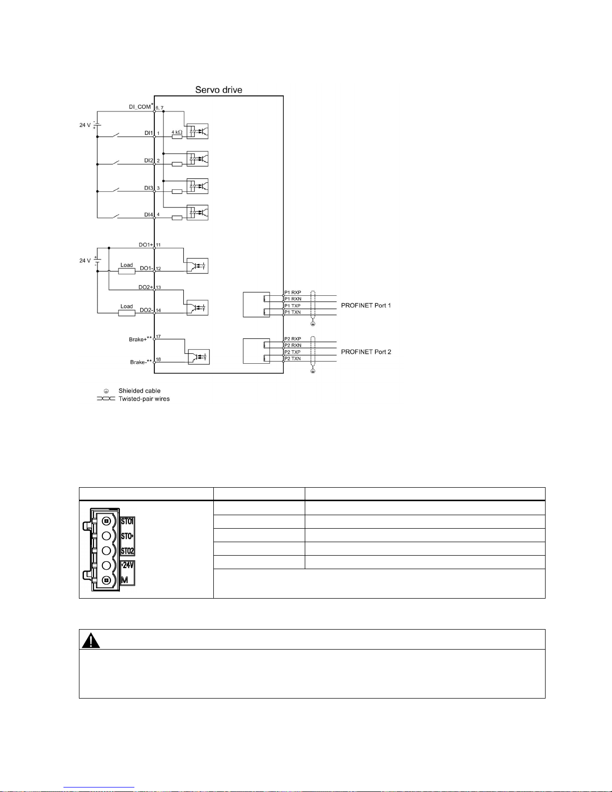
Getting Started
A5E37208904-003, 04/2017
49
Example 2
* Digital inputs, supporting both PNP and NPN types.
** The pins are used to connect the brake control signals for 200
V variant drive only. Refer to the section "Motor holding
brake" in SINAMICS V90, SI
MOTICS S-1FL6 Operating Instructions for the detailed connections.
4.4
24 V power supply/STO
The pin assignment for the 24 V power supply/STO interface is shown as follows:
Interface
Signal name
Description
STO 1
Safe torque off channel 1
STO +
Specific power supply for safe torque off
STO 2
Safe torque off channel 2
+24 V
Power supply, 24 VDC
M
Power supply, 0 VDC
Maximum conductor cross-section: 1.5 mm2
Wiring
WARNING
Material damages and personal injuries by the drop of a hanging axis
When the servo system is used as a hanging axis, the axis will drop if the positive and negative poles of the 24 V power
supply are connected inversely. Unexpected drop of the hanging axis may cause material damages and personal injuries.
Make sure that the 24 V power supply is correctly connected.
Page 50
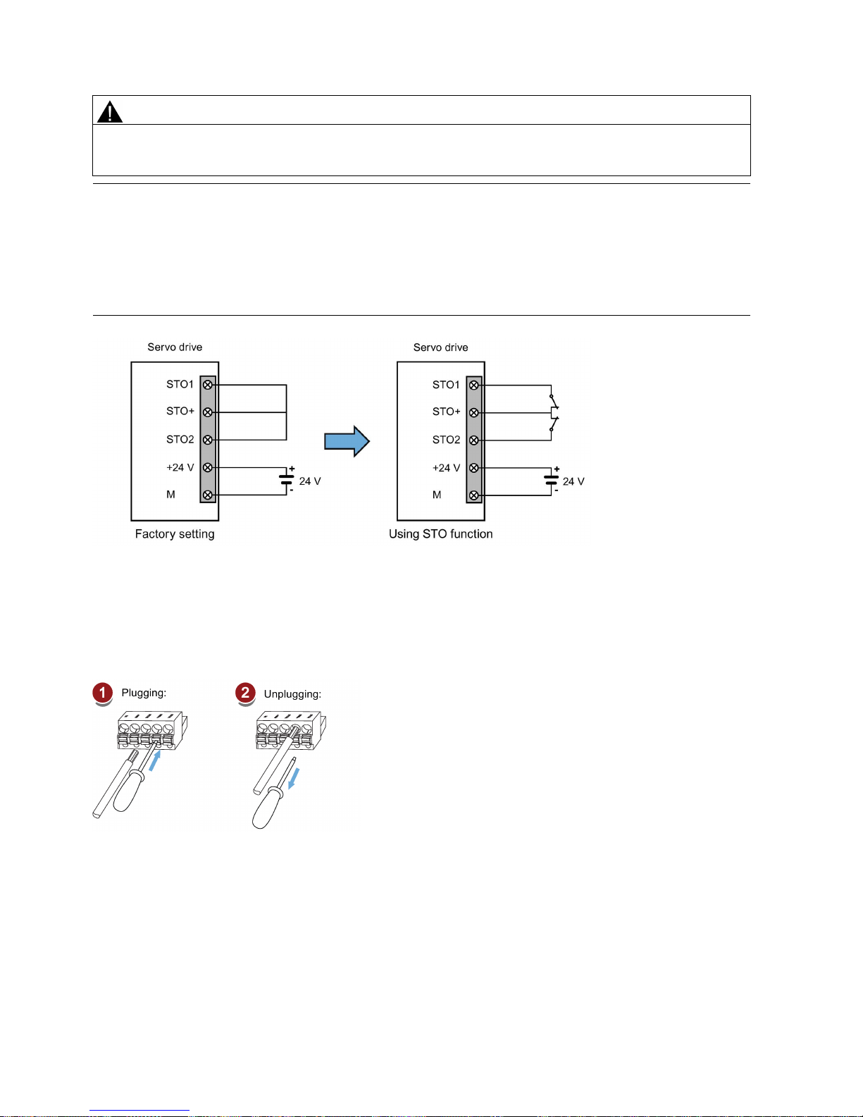
Getting Started
50 A5E37208904-003, 04/2017
WARNING
Material damages and personal injuries by the drop of a hanging axis
It is not allowed to use the STO with a hanging axis because the axis may drop. Unexpected drop of the hanging axis may
cause material damages and personal injuries.
Note
Using the STO function
The STO1, STO+ and STO2 are short connected at the factory setting.
When the STO function is to be used, you must remove the
short-circuit stick before connecting the STO interfaces. The
safety function of the servo drive is SIL 2 (EN61800
-5-2). If you do not need to use it any more, you must reinsert the short-
circuit stick; otherwise, the motor will not run.
For detailed infor
mation about the STO function, refer to chapter "Safety Integrated basic functions" of SINAMICS V90,
SIMOTICS S
-1FL6 Operating Instructions.
Assembling the 24 V power supply and STO cable terminals
The procedure of assembling a 24 V power cable terminal or an STO cable terminal is the same as that for a power cable
terminal on the drive side of the V90 PN 200 V servo drives.
For more information, see the SINAMICS V90, SIMOTICS S-1FL6 Operating Instructions.
Plugging the 24 V power supply and STO cables
Page 51
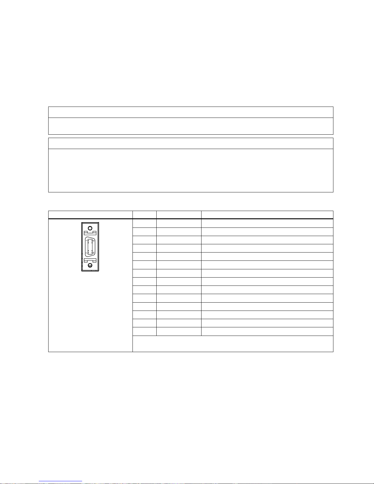
Getting Started
A5E37208904-003, 04/2017
51
4.5
Encoder interface - X9
The SINAMICS V90 PN 200V variant servo drive supports two kinds of encoders:
● Incremental encoder TTL 2500 ppr
● Absolute encoder single-turn 21-bit
The SINAMICS V90 PN 400V variant servo drive supports two kinds of encoders:
● Incremental encoder TTL 2500 ppr
● Absolute encoder 20-bit + 12-bit multi-turn
NOTICE
Cable shielding
The encoder cable
must
be shielded to meet the EMC requirements.
NOTICE
Drive damage caused by short-circuiting between the shielding wire and the unused pin on the encoder connector
The shielding wire may inadvertently be short-circuited to the unused pin on the to-be-assembled encoder connector. This
can cause damage to the drive.
Exercise caution when connecting the shielding cable to the encoder connector.
For more information, see Section "Assembly of cable terminals on the drive side" in the SINAMICS V90, SIMOTICS S-
1FL6 Operating Instructions.
Encoder interface - drive side
Illustration
Pin No.
Signal name
Description
1
Biss_DataP
Absolute encoder data signal, positive
2
Biss_DataN
Absolute encoder data signal, negative
3
Biss_ClockN
Absolute encoder clock signal, negative
4
Biss_ClockP
Absolute encoder clock signal, positive
5
P5V
Encoder power supply, 5 V
6
P5V
Encoder power supply, 5 V
7
M
Encoder power supply, grounding
8
M
Encoder power supply, grounding
9
Rp
Encoder R phase positive signal
10
Rn
Encoder R phase negative signal
11
Bn
Encoder B phase negative signal
12 Bp Encoder B phase positive signal
13
An
Encoder A phase negative signal
14
Ap
Encoder A phase positive signal
Screw type: UNC 4-40 (plug-in terminal block)
Tightening torque: 0.4 Nm
Page 52
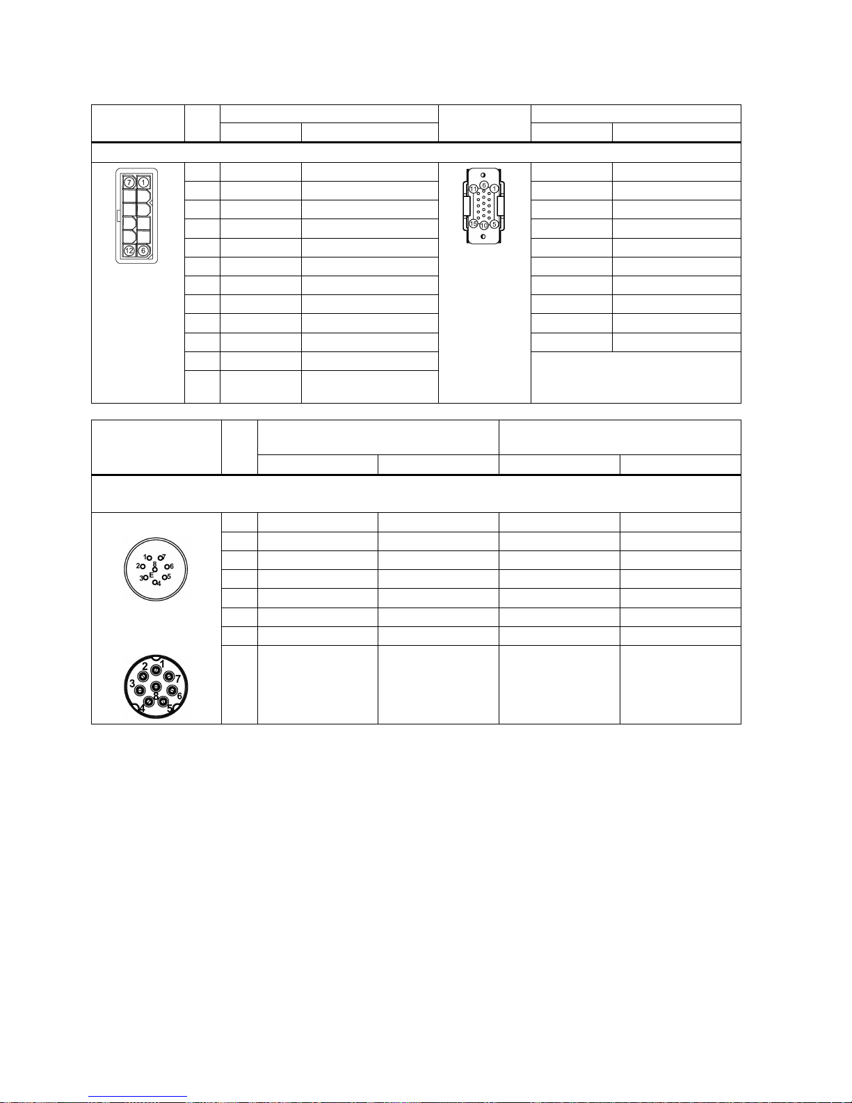
Getting Started
52 A5E37208904-003, 04/2017
Encoder connector - motor side
Illustration
Pin
No.
Incremental encoder TTL 2500 ppr
Illustration
Absolute encoder single-turn 21-bit
Signal
Description
Signal
Description
Low inertia motor, shaft height: 20 mm, 30 mm and 40 mm
1
P_Supply
Power supply 5 V
P_Supply
Power supply 5 V
2 M Power supply 0 V
M
Power supply 0 V
3
A+
Phase A+
Clock_P
Clock
4
B+
Phase B+
Data_P
Data
5
R+
Phase R+
n. c.
Not connected
6
n. c.
Not connected
P_Supply
Power supply 5 V
7 P_Supply Power supply 5 V M Power supply 0 V
8 M Power supply 0 V
Clock_N
Inverted clock
9 A- Phase A- Data_N Inverted data
10
B-
Phase B-
Shielding
Grounding
11
R-
Phase R-
Note
The pin11 to pin15 of the absolute
encoder connector are not connected.
12 Shielding Grounding
Illustration
Pin
No.
Incremental encoder TTL 2500 ppr
Absolute encoder single-turn 21-bit
Absolute encoder 20-bit + 12-bit multi-turn
Signal
Description
Signal
Description
Low inertia motor, shaft height: 50 mm
High inertia motor, shaft height: 45 mm, 65 mm, and 90 mm
Straight connectors:
Angular connectors
(for high inertia motors
only):
1
P_Supply
Power supply 5 V
P_Supply
Power supply 5 V
2 M Power supply 0 V
M
Power supply 0 V
3
A+
Phase A+
n. c.
Not connected
4
A-
Phase A-
Clock_N
Inverted clock
5
B+
Phase B+
Data_P
Data
6
B-
Phase B-
Clock_P
Clock
7
R+
Phase R+
n. c.
Not connected
8 R- Phase R- Data_N Inverted data
Page 53
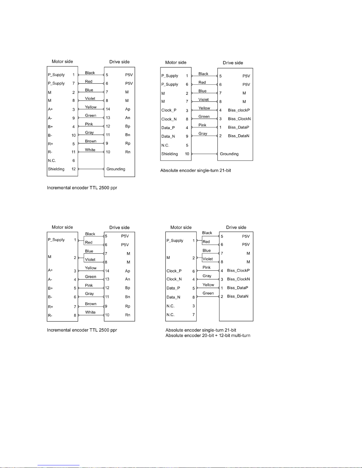
Getting Started
A5E37208904-003, 04/2017
53
Wiring
Low inertia motor, shaft height: 20 mm, 30 mm and 40 mm
Low inertia motor, shaft height: 50 mm
High inertia motor, shaft height: 45 mm, 65 mm, and 90 mm
Page 54
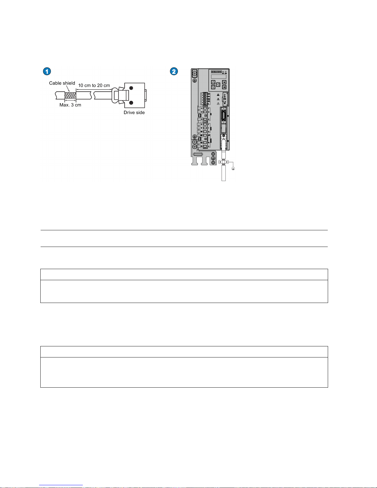
Getting Started
54 A5E37208904-003, 04/2017
Grounding
To ensure better EMC effects, you are recommended to strip the encoder cable and connect the cable shield to earth, as
shown in the following figure:
4.6
External braking resistor - DCP, R1
The SINAMICS V90 PN has been designed with an internal braking resistor to absorb regenerative energy from the motor.
When the internal braking resistor cannot meet the braking requirements (e.g. the alarm A52901 is generated), you can
connect an external braking resistor. For more information about how to select a braking resistor, see Section "Accessories"
in the SINAMICS V90, SIMOTICS S-1FL6 Operating Instructions.
Note
The 200 V variant servo drive with rated power of 0.1 kW (FSB) does not have a built
-in resistor.
Connecting an external braking resistor
NOTICE
Damage to the drive
Before connecting an external resistor to DCP and R1, remove the connection between terminals DCP and R2; otherwise,
the drive may be damaged.
For more information about how to connect the external braking resistor, see Section "System connection (Page 40)".
4.7
Motor holding brake
You can connect the SINAMICS V90 PN servo drive to a servo motor with brake to use the function of motor holding brake.
NOTICE
Shortening the service life of motor brake
The motor brake is used for holding purpose only. Frequent emergency stops with the motor brake will shorten its service
life.
Unless absolutely necessary, do not apply the motor brake as an emergency stop or deceleration mechanism.
Page 55
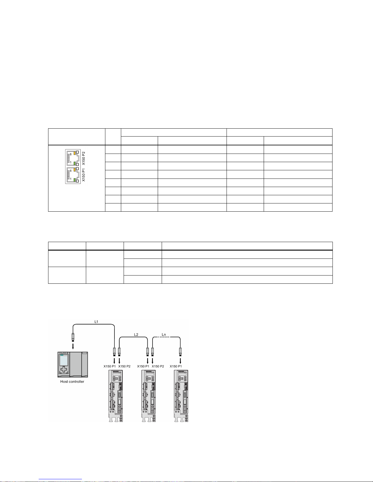
Getting Started
A5E37208904-003, 04/2017
55
4.8
PROFINET interface - X150
PROFINET interface
PROFINET devices from the SINAMICS family have a PROFINET interface (Ethernet-controller/interface) with two ports
(physical connection possibilities).
Every PROFINET device on the network is uniquely identified via its PROFINET interface. For this purpose, each
PROFINET interface has:
● A MAC address (factory default)
● An IP address
● A device name (name of the station)
Illustration
Pin
PROFINET communication port 1 - P1
PROFINET communication port 2 - P2
Signal
Description
Signal
Description
1
P1RXP
Port 1 receive data +
P2RXP
Port 2 receive data +
2
P1RXN
Port 1 receive data -
P2RXN
Port 2 receive data -
3
P1TXP
Port 1 transmit data +
P2TXP
Port 2 transmit data +
4
PE terminal
Protective earthing
PE terminal
Protective earthing
5
PE terminal
Protective earthing
PE terminal
Protective earthing
6
P1TXN
Port 1 transmit data -
P2TXN
Port 2 transmit data -
7
PE terminal
Protective earthing
PE terminal
Protective earthing
8
PE terminal
Protective earthing
PE terminal
Protective earthing
LED displays
For diagnostic purposes, the RJ45 sockets are each equipped with a green and an orange LED. This allows the following
status information about the respective PROFINET port to be displayed:
Name
Color
Status
Meaning
Link Green lit Transfer rate 100 Mbit/s
off
No or faulty connection
Activity Orange
lit
Data exchange
off
No data exchange
Wiring
The maximum length of cables between stations (L1 to Ln) is 100 m. For a long cable, you are recommended to fix it on the
cabinet to prevent the connector damage caused by dragging.
Page 56
Getting Started
56 A5E37208904-003, 04/2017
Note
When connecting the ports P1 and P2, you need to make sure that the physical input and output connections are the same
with the connections in the topology.
5
Commissioning
Prior to commissioning, read "Introduction to the BOP (Page 57)" for more information about the BOP operations. In case of
any faults or alarms during commissioning, refer to Chapter "Diagnostics (Page 114)" for detailed description.
CAUTION
Carefully read the safety instructions
Before your commissioning or operation, read the safety instructions in Chapter "Fundamental safety instructions (Page 3)"
carefully. Failure to observe the instructions may cause serious effects.
WARNING
Material damages and personal injuries by the drop of a hanging axis
When the servo system is used as a hanging axis, the axis will drop if the positive and negative poles of the 24 V power
supply are connected inversely. Unexpected drop of the hanging axis may cause material damages and personal injuries.
Before commissioning, a crosstie must be used to hold the hanging axis in prevention of an unexpected drop. In addition,
make sure that the 24 V power supply is correctly connected.
NOTICE
Firmware damage due to drive power-off during data transfer
Switching off the 24 V power supply for the drive during data transfer from the micro SD card/SD card to the drive can
cause damage to the drive firmware.
• Do not switch off the drive power supply when the data transfer from the micro SD card/SD card to the drive is in
process.
NOTICE
Existing setting data may be overwritten by the setting data on the micro SD card/SD card during startup.
•
When a drive is switched on with a micro SD card/SD card containing user setting data, the existing setting data on the
drive will be overwritten.
• When a drive is switched on with a micro SD card/SD card containing no user setting data, the drive will automatically
save the existing user setting data onto the micro SD card/SD card.
Before starting up the drive with a micro SD card/SD card, check whether the micro SD card/SD card contains user setting
data. Otherwise, the existing data on the drive may be overwritten.
Note
Plugging or unplugging the micro SD card/SD card will cause startup failure.
Do not plug or unplug the micro SD card/SD card during startup; otherwise, the drive will fail to start up.
Note
In S control mode, if the m
otor shaft is blocked, the blocked torque is the current effective torque. Long time shaft blocking
can cause damage to the motor.
Engineering tool - SINAMICS V-ASSISTANT
You can use the engineering tool SINAMICS V-ASSISTANT to perform the trial operation.
SINAMICS V-ASSISTANT is a software tool that can be installed on a PC and runs on the Windows operating system. It
communicates with the SINAMICS V90 PN servo drive with a USB cable (To ensure the stability of online commissioning,
Siemens recommends you to use a shielded USB cable of no longer than 3 m with ferrite cores on both ends.). With
SINAMICS V-ASSISTANT, you can change drive parameters and monitor drive working states in online mode.
For more information, refer to SINAMICS V-ASSISTANT Online Help. You can search and download SINAMICS VASSISTANT from Technical support website (https://support.industry.siemens.com/cs/ww/en/).
Page 57
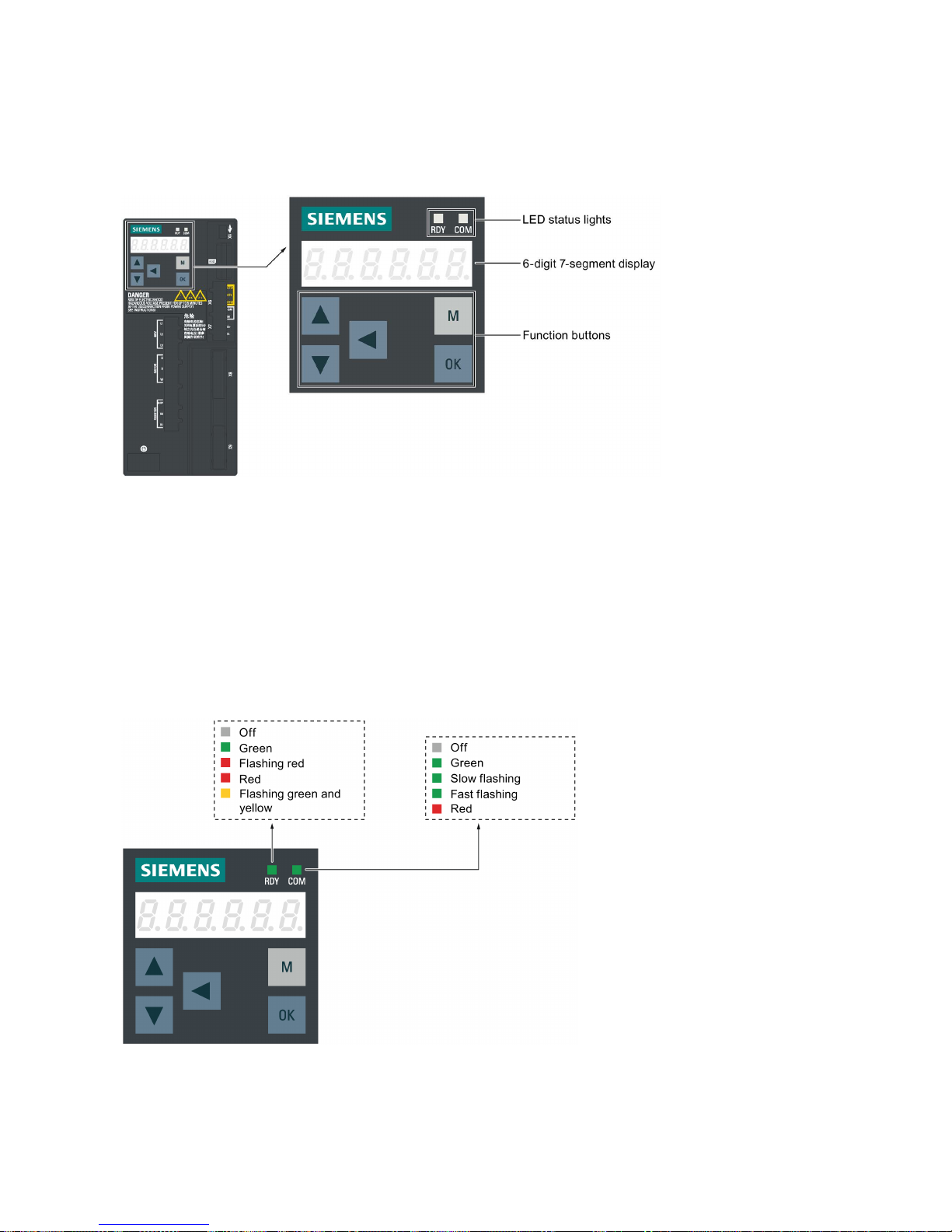
Getting Started
A5E37208904-003, 04/2017
57
5.1
Introduction to the BOP
Overview
The SINAMICS V90 PN servo drive is designed with a Basic Operator Panel (BOP) on the front panel of the servo drive:
You can use the BOP for the following operations:
● Standalone commissioning
● Diagnosis
● Parameter access
● Parameter settings
● Micro SD card/SD card operations
● Drive restart
LED status indicators
Two LED status indicators (RDY and COM) are available to indicate drive status. Both LEDs are tricolor (green/red/yellow).
Page 58
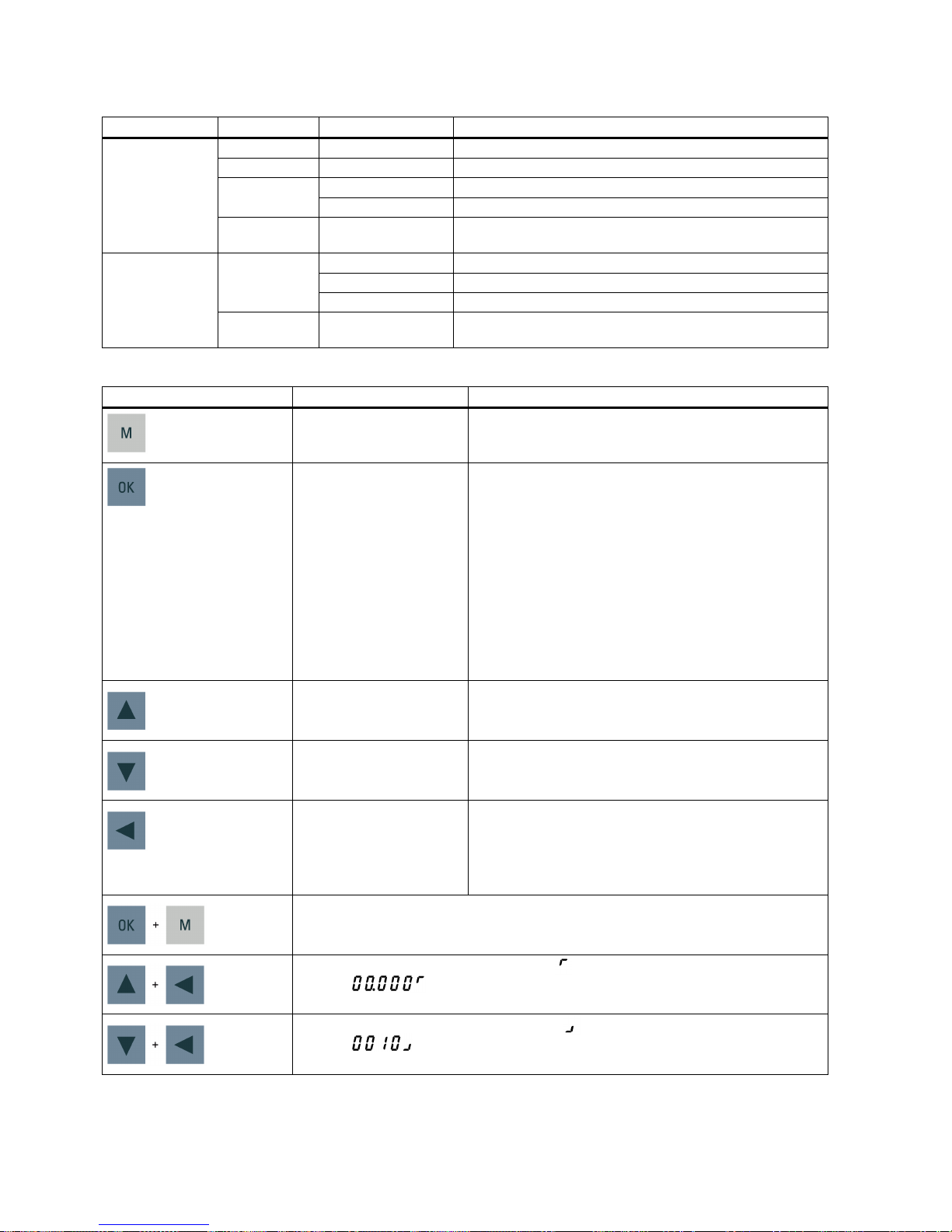
Getting Started
58 A5E37208904-003, 04/2017
You can find detailed information about the status indications in the table below:
Status indicator
Color
Status
Description
RDY
-
Off
24 V control board power supply is missing
Green
Continuously lit
The drive is in "servo on" state
Red
Continuously lit
The drive is in "servo off" state or in the startup state
Flash at 1 Hz
Alarms or faults occurs
Green and
yellow
Flash alternatively at
2 Hz
Drive identification
COM
Green
Continuously lit
PROFINET communication is working with IRT
Flash at 0.5 Hz
PROFINET communication is working with RT
Flash at 2 Hz
Micro SD card/SD card operating (read or write)
Red Continuously lit Communication error (always put the PROFINET communica-
tion error as the first consideration)
Control buttons
Button
Description
Functions
M button
• Exits from the current menu
• Switches between operating modes in the top level
menu
OK button
Short-pressing:
• Confirms selection or input
• Enters sub menu
• Acknowledges faults
Long-pressing:
Activates auxiliary functions
• JOG
• Saves parameter set in drive (RAM to ROM)
• Sets parameter set to default
• Transfers data (drive to micro SD card/SD card)
• Transfers data (micro SD card/SD card to drive)
•
Updates firmware
UP button
• Navigates to the next item
• Increases a value
• JOG in CW (clockwise)
DOWN button
• Navigates to the previous item
• Decreases a value
• JOG in CCW (counter-clockwise)
SHIFT button Moves the cursor from digit to digit for single digit editing,
including the digit of positive/negative sign
Note:
When the sign is edited, "_" indicates positive and "-" indi-
cates negative.
Press the key combination for four seconds to restart the drive
Moves current display to the left page when
is displayed at the upper right corner, for
example .
Moves current display to the right page when
is displayed at the lower right corner, for
example .
Page 59
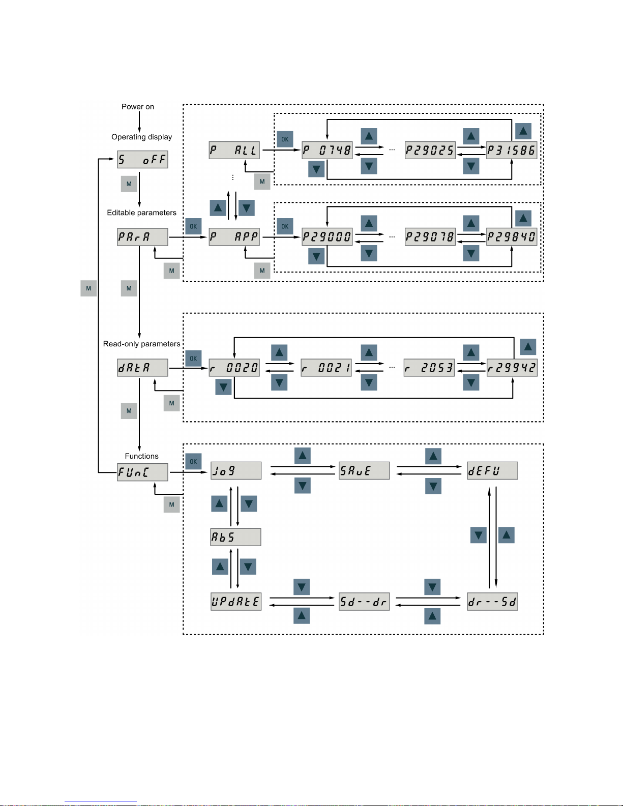
Getting Started
A5E37208904-003, 04/2017
59
Menu structure
The overall parameter structure of SINAMICS V90 PN BOP is designed as follows:
Page 60
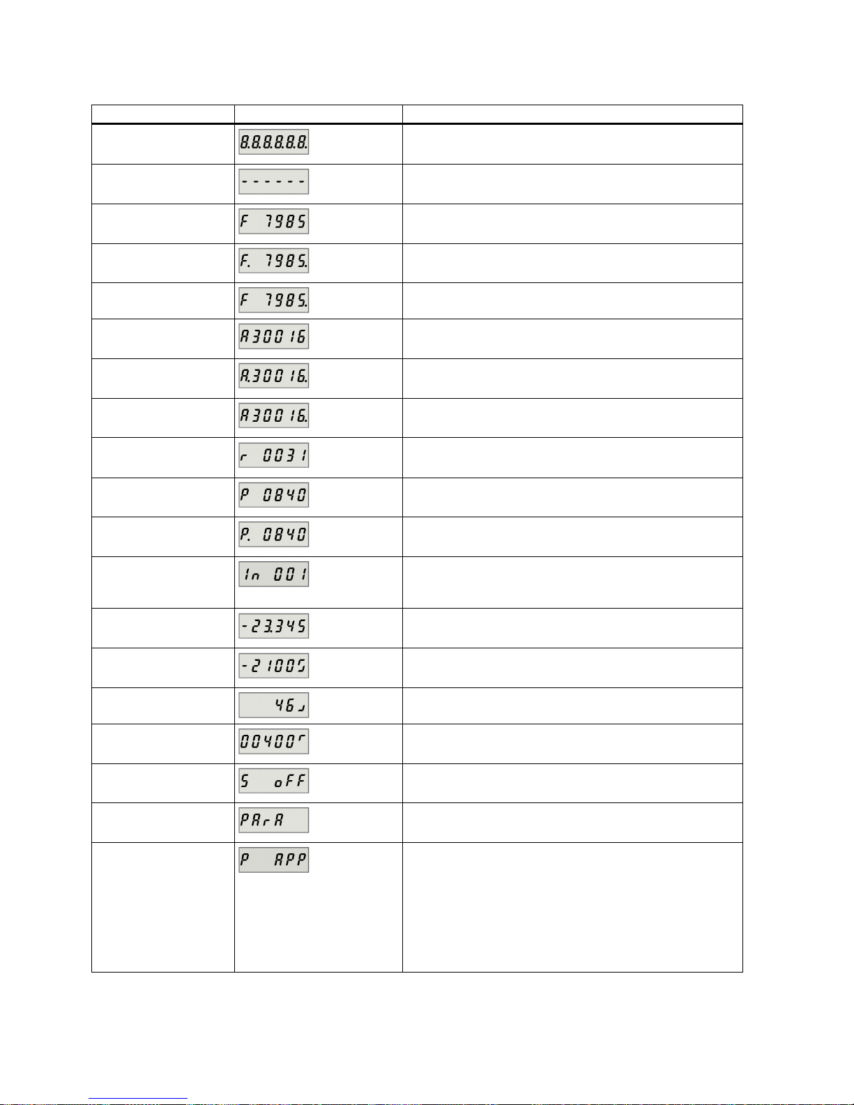
Getting Started
60 A5E37208904-003, 04/2017
BOP displays
Display
Example
Description
8.8.8.8.8.8.
Drive is in startup state
------ Drive is busy
Fxxxxx
Fault code, in the case of a single fault
F.xxxxx.
Fault code of the first fault, in the case of multiple faults
Fxxxxx.
Fault code, in the case of multiple faults
Axxxxx
Alarm code, in the case of a single alarm
A.xxxxx.
Alarm code of the first alarm, in the case of multiple alarms
Axxxxx.
Alarm code, in the case of multiple alarms
Rxxxxx
Parameter number, read-only parameter
Pxxxxx
Parameter number, editable parameter
P.xxxxx
Parameter number, editable parameter; the dot means that at
least one parameter has been changed
In xxx
Indexed parameter
Figure after "In" indicates the number of indices.
For example, "In 001" means that this indexed parameter is 1.
xxx.xxx
Negative parameter value
xxx.xx<>
Current display can be moved to left or right
xxxx.xx>
Current display can be moved to right
xxxx.xx<
Current display can be moved to left
S Off
Operating display: servo off
Para
Editable parameter group
P xxxx
Parameter group
Five groups are available:
1.
P APP
: application
2.
P BASE
: basic
3.
P CON
: communication
4.
P EPOS
: basic positioner
5.
P ALL
: all parameters
Page 61
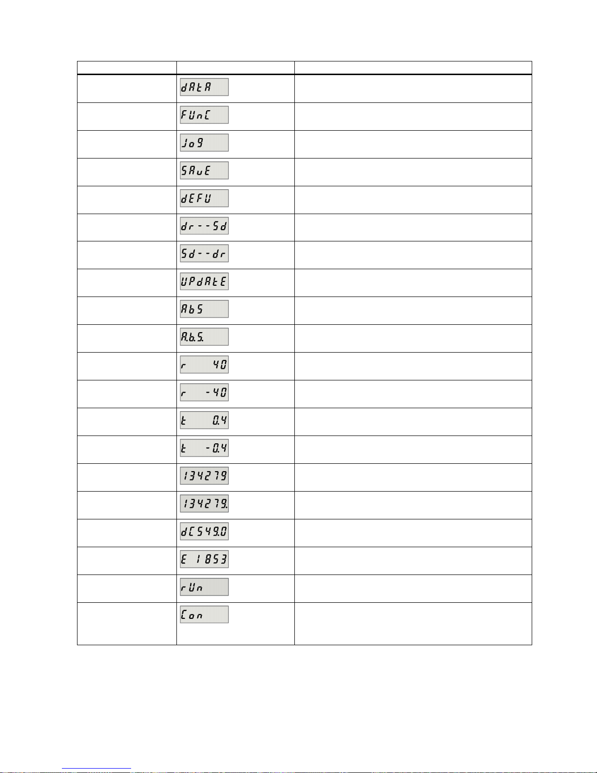
Getting Started
A5E37208904-003, 04/2017
61
Display
Example
Description
Data
Read-only parameter group
Func
Function group
JOG JOG function
Save
Save data in drive
defu
Restore drive to default settings
dr--sd
Save data from drive to micro SD card/SD card
sd--dr
Upload data from micro SD card/SD card to drive
Update
Update firmware
ABS
The zero position has not been set
A.B.S.
The zero position has been set
r xxx
Actual speed (positive direction)
r -xxx
Actual speed (negative direction)
T x.x
Actual torque (positive direction)
T -x.x
Actual torque (negative direction)
xxxxxx
Actual position (positive direction)
xxxxxx.
Actual position (negative direction)
DCxxx.x
Actual DC link voltage
Exxxxx
Position following error
run The motor is running
Con The communication between the commissioning tool
SINAMICS V-ASSISTANT and the servo drive is established.
In this case, the BOP is protected from any operations except
clearing alarms and acknowledging faults.
Page 62
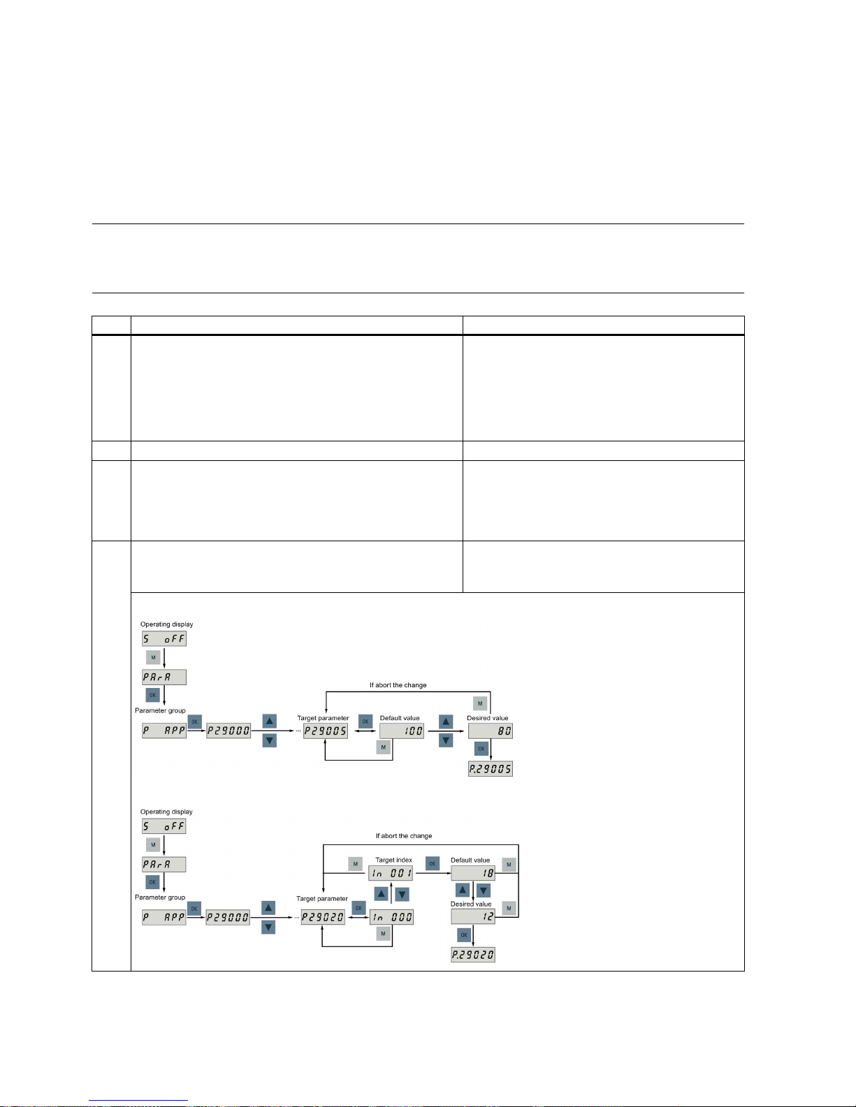
Getting Started
62 A5E37208904-003, 04/2017
5.2
Initial commissioning in JOG mode
Prerequisites
● The servo drive is connected to the servo motor without load
● The servo drive is not in servo on status
Operating sequence
Note
Set bit 0 of parameter p29108 to 1, and then save the parameter setting and restart the drive, to enable the JOG function;
otherwise, you cannot access the function related parameter p1058.
If you have assigned digita
l signal EMGS, keep it at a high level (1) to ensure normal operation.
Step
Description
Remarks
1 Connect necessary units and check wiring. It is necessary to connect the following cables:
• Power cable
• Encoder cable
• Brake cable
• Line supply cable
•
24 VDC cable
2 Switch on the 24 VDC power supply.
3 Check the servo motor type.
• If the servo motor has an incremental encoder, input
motor ID (p29000).
• If the servo motor has an absolute encoder, the servo
drive can identify the servo motor automatically.
Fault
F52984
occurs when the servo motor is not
identified.
You can find the motor ID from the motor rating
plate. Go to "Motor components (Page 14)" for
detailed descriptions about motor rating plate.
4 Check the direction of motor rotation.
The default direction of rotation is CW (clockwise). You can
change it by setting the parameter p29001 if necessary.
p29001=0: CW
p29001=1: CCW
Setting a parameter without index (example)
Setting a parameter with index (example)
Page 63
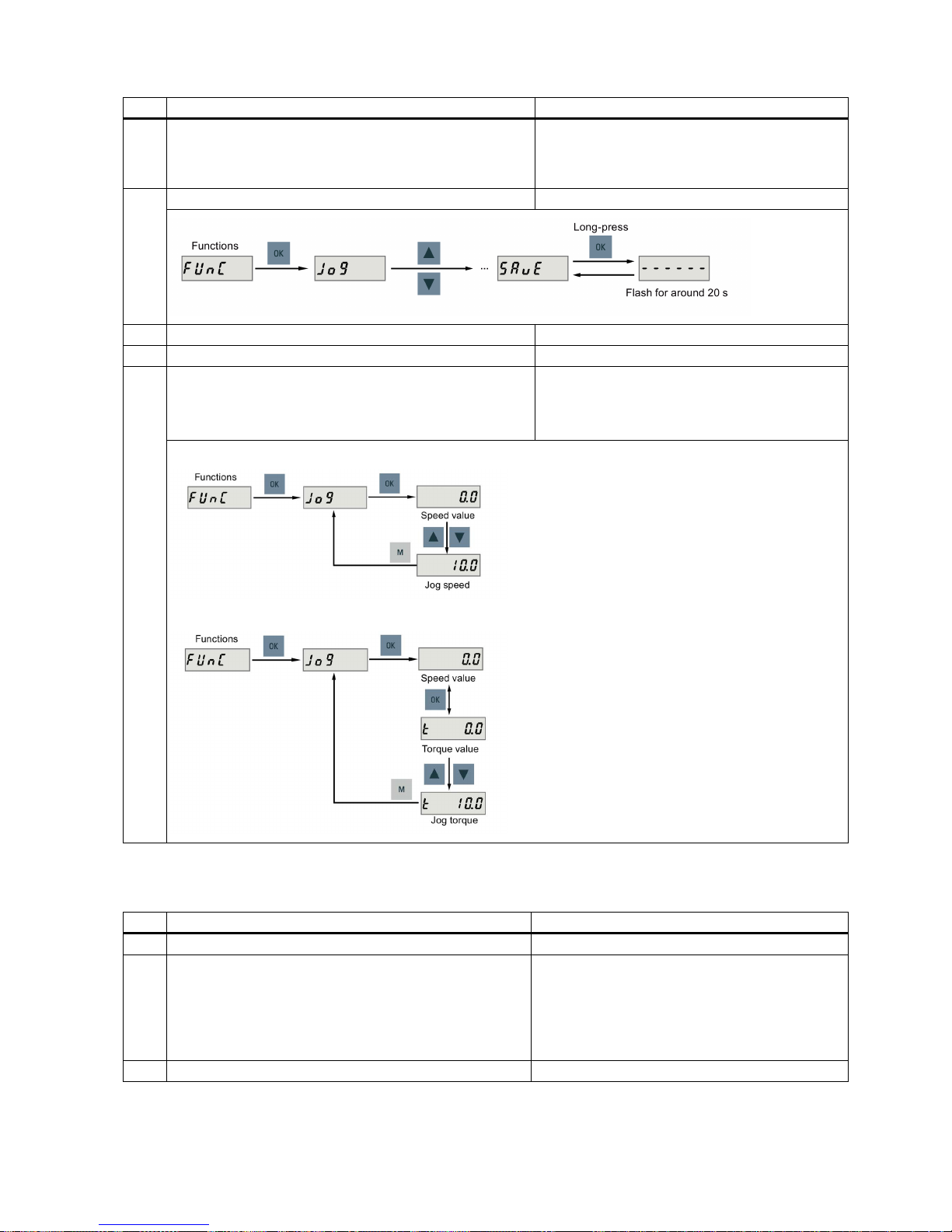
Getting Started
A5E37208904-003, 04/2017
63
Step
Description
Remarks
5 Check the JOG speed.
The default JOG speed is 100 rpm. You can change it by
setting the parameter p1058.
Set bit 0 of parameter p29108 to 1, and then save
the parameter setting and restart the drive, to enable the JOG function; otherwise, you cannot access
p1058.
6
Save parameters with the BOP.
7 Switch on the main line supply.
8
Clear faults and alarms.
Refer to "Diagnostics (Page 114)".
9 For the BOP, enter the JOG menu function and press the UP
or
DOWN
button to run the servo motor.
For the engineering tool, use the JOG function to run the
servo motor.
For more information about JOG with SINAMICS VASSISTANT, see SINAMICS V-ASSISTANT Online
Help.
JOG in speed (example)
JOG in torque (example)
5.3
Commissioning in basic positioner control mode (EPOS)
The following takes the EJOG function for example to describe the commissioning in EPOS mode.
Step
Description
Remarks
1
Switch off the main line supply.
2 Power off the servo drive and connect it to the controller (for
example, SIMATIC S7-1500) with the PROFINET cable and
signal cable.
If any one of digital signals EMGS, CWL, and CCWL
is not assigned to a DI, it will be set to a high level
(1) automatically.
If you have assigned any one of digital signals
EMGS, CWL, and CCWL to a DI, keep it at a high
level (1).
3
Switch on the 24 VDC power supply.
Page 64
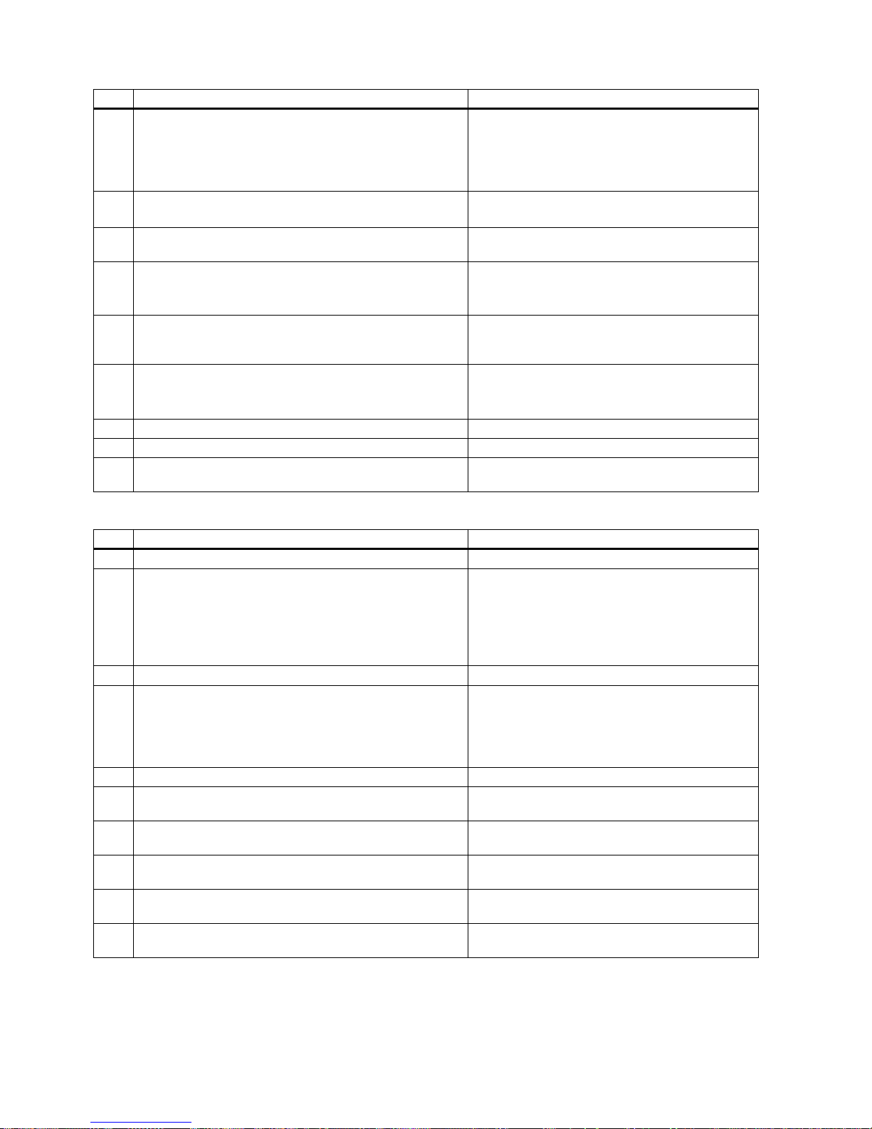
Getting Started
64 A5E37208904-003, 04/2017
Step
Description
Remarks
4 Check the servo motor type.
• If the servo motor has an incremental encoder, input the
motor ID (p29000).
• If the servo motor has an absolute encoder, the servo
drive can identify the servo motor automatically.
Fault
F52984
occurs when the servo motor is not
identified.
You can find the motor ID from the motor rating
plate. For the detailed information of the motor rating
plate, see Section "Motor components (Page 14)".
5 Switch to the basic positioner control mode by setting pa-
rameter p29003 = 1.
•
p29003 = 1: basic positioner control (EPOS)
•
p29003 = 2: speed control (S)
6 Save the parameter and restart the servo drive to apply the
setting of the basic positioner control mode.
7 Set the mechanical gear ratio with parameters p29247,
p29248 and p29249.
• p29247: LU per load revolution
• p29248: load revolutions
•
p29249: motor revolutions
8 Select the axis type by setting parameter p29245. If you use
the modular axis, you need to define the modular range by
setting parameter p29246.
• p29245 = 0: linear axis
• p29245 = 1: modular axis
9 Setting jogging setpoints with the appropriate parameters.
• Velocity (p2585, p2586)
•
Incremental (p2587, p2588)
Refer to "EJOG (Page 67)".
10
Switch on the main line supply.
11
Set up the PROFINET configuration with TIA Portal.
12 Select the telegram for PROFINET communication with
parameter p0922.
5.4
Commissioning in speed control mode (S)
Step
Description
Remarks
1
Switch off the main line supply.
2 Power off the servo drive and connect it to the controller (for
example, SIMATIC S7-1500) with the PROFINET cable and
signal cable.
If any one of digital signals EMGS, CWL, and CCWL
is not assigned to a DI, it will be set to a high level
(1) automatically.
If you have assigned any one of digital signals
EMGS, CWL, and CCWL to a DI, keep it at a high
level (1).
3
Switch on the 24 VDC power supply.
4 Check the servo motor type.
• If the servo motor has an incremental encoder, input
motor ID (p29000).
• If the servo motor has an absolute encoder, the servo
drive can identify the servo motor automatically.
Fault
F52984
occurs when the servo motor is not
identified.
You can find the motor ID from the motor rating
plate. Go to "Motor components (Page 14)" for de-
tailed descriptions about motor rating plate.
5 Set up the PROFINET configuration with TIA Portal.
6 Select the telegram for PROFINET communication with
parameter p0922.
7 Set the IP address for the station with parameters p8921,
p8923.
8 Set the device name for the station with parameter p8920. The device name must be unique within the
PROFINET network.
9 Active the IP configuration and device name with parameter
p8925.
10 Set the torque limitation and speed limitation. Refer to "Torque limit (Page 66)" and "Speed limit
(Page 65)".
Page 65
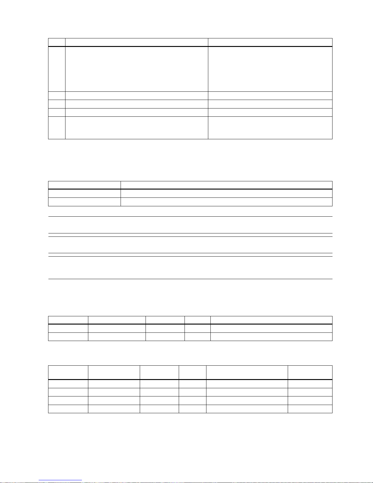
Getting Started
A5E37208904-003, 04/2017
65
Step
Description
Remarks
11 Configure necessary digital input signals by setting the fol-
lowing parameters:
• p29301: DI1
• p29302: DI2
• p29303: DI3
•
p29304: DI4
The factory settings are:
• p29301: 2 (RESET)
• p29302: 11 (TLIM)
• p29303: 0
• p29304: 0
12 Save parameters with the BOP and restart the drive.
13
Switch on the main line supply.
14
Clear faults and alarms.
Refer to "Diagnostics (Page 114)".
15 Send and receive the process data (PZD) with TIA Portal. The actual speed of the servo motor can be viewed
from the BOP operating display.
The default display is the actual speed.
5.5
Commissioning control functions
5.5.1
Speed limit
Two sources in total are available for the speed limit. You can select one of them via the digital input signal SLIM:
Digital signal (SLIM)
Speed limit
0
Internal speed limit 1
1
Internal speed limit 2
Note
The bit 0 of parameter p29108 must
be set to 1 to enable the speed limit function.
Note
You can switch between the two sources and modify their values when the servo drive is running.
Note
Fault F7901 occ
urs when the actual speed exceeds the positive speed limit + hysteresis speed (p2162) or the negative
speed limit
- hysteresis speed (p2162).
Overall speed limit
Besides the above two channels, an overall speed limit is also available.
You can configure the overall speed limit by setting the following parameters:
Parameter
Value range
Default
Unit
Description
p1083
0 to 210000
210000
rpm
Overall speed limit (positive)
p1086
-210000 to 0
-210000
rpm
Overall speed limit (negative)
Internal speed limit
Select an internal speed limit by setting the following parameters:
Parameter
Value range
Default
Unit
Description
Digital input
(SLIM)
p29070[0]
0 to 210000
210000
rpm
Internal speed limit 1 (positive)
0
p29070[1]
0 to 210000
210000
rpm
Internal speed limit 2 (positive)
1
p29071[0]
-210000 to 0
-210000
rpm
Internal speed limit 1 (negative)
0
p29071[1]
-210000 to 0
-210000
rpm
Internal speed limit 2 (negative)
1
Page 66
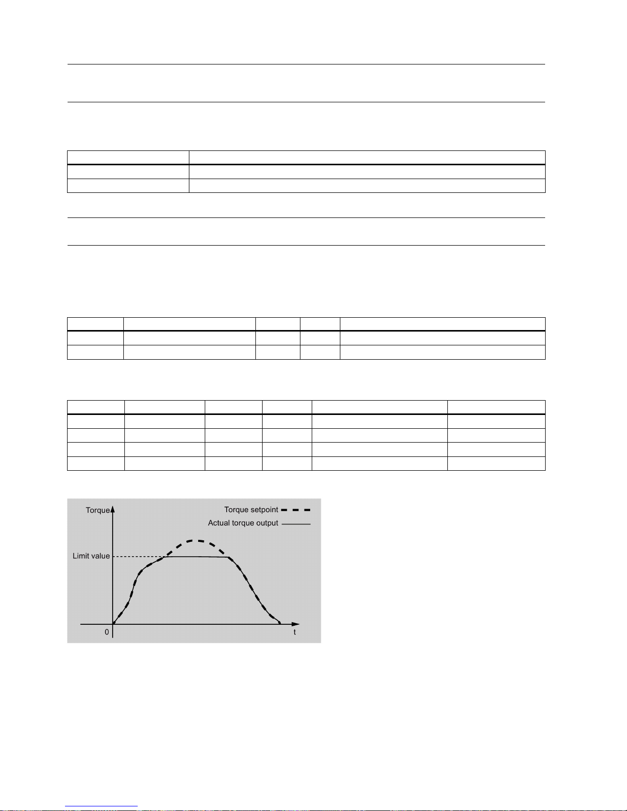
Getting Started
66 A5E37208904-003, 04/2017
Note
After the motor is commissioned, p1082, p1083, p1086, p29070 and p29071 are set to the maximum speed of the motor
automatically.
5.5.2
Torque limit
Two sources in total are available for the torque limit. You can select one of them via the digital input signal TLIM:
Digital input (TLIM)
Torque limit
0
Internal torque limit 1
1
Internal torque limit 2
When the torque setpoint reaches torque limit, the torque is limited to the value selected by TLIM.
Note
You can switch between the two sources and modify their values when the servo drive is running.
Overall torque limit
Besides the above two sources, an overall torque limit is also available. The overall torque limit takes effect when an
emergency stop (OFF3) happens. In this case, the servo drive brakes with a maximum torque.
You can configure the overall torque limit by setting the following parameters:
Parameter
Value range
Default
Unit
Description
p1520
-1000000.00 to 20000000.00
0
Nm
Overall torque limit (positive)
p1521 -20000000.00 to 1000000.00 0 Nm Overall torque limit (negative)
Internal torque limit
Select an internal torque limit by setting the following parameters:
Parameter
Value range
Default
Unit
Description
Digital input (TLIM)
p29050[0]
-150 to 300
300
%
Internal torque limit 1 (positive)
0
p29050[1]
-150 to 300
300
%
Internal torque limit 2 (positive)
1
p29051[0] -300 to 150 -300 % Internal torque limit 1 (negative) 0
p29051[1]
-300 to 150
-300
%
Internal torque limit 2 (negative)
1
The following diagram shows how the internal torque limit functions:
Torque limit reached (TLR)
When the generated torque has nearly (internal hysteresis) reached the value of the positive torque limit or negative torque
limit, the signal TLR is output.
Page 67

Getting Started
A5E37208904-003, 04/2017
67
5.5.3
EJOG
When telegrams 7, 9, 110, and 111 are used, select a jogging channel with the PROFINET control words STW1.8 and
STW1.9:
Control word
Setting
Description
STW1.8
STW1.9
0
No jogging channel activated.
1
Jog 1 signal source rising edge activated.
2
Jog 2 signal source rising edge activated.
3
Reserved.
Features
Selecting a jogging mode
When telegram 110 is used, select a jogging mode with the PROFINET control word POS_STW.5:
Control word
Setting
Description
POS_STW.5
1
Jogging, incremental active.
0
Jogging, velocity active.
When telegram 111 is used, select a jogging mode with the PROFINET control word POS_STW2.5:
Control word
Setting
Description
POS_STW2.5
1
Jogging, incremental active.
0
Jogging, velocity active.
Note
When telegrams 7 and 9 are used, endless jogging is fixed.
Setting jogging setpoints
When telegrams 7 and 9 are used, set the following jogging setpoint with the appropriate parameters:
● Velocity (p2585, p2586)
When telegrams 110, and 111 are used, set the following jogging setpoints with the appropriate parameters:
● Velocity (p2585, p2586)
● Incremental (p2587, p2588)
Overview of important parameters
•
p2585
EPOS jog 1 setpoint veloc
ity
•
p2586
EPOS jog 2 setpoint velocity
•
p2587
EPOS jog 1 travel distance
•
p2588
EPOS jog 2 travel distance
For more information about the parameters above, see Section "Parameter list (Page 84)".
Page 68

Getting Started
68 A5E37208904-003, 04/2017
6
PROFINET communication
PROFINET IO is a real time protocol based on Ethernet. It is used as high level network for industrial automation
applications. PROFINET IO focuses on the data exchange for a programmable controller. A PROFINET IO network consists
of the following devices:
● IO controller: typically, it is the PLC, which controls the whole application
● IO device: a decentralized IO device (for example, encoder, sensor), which is controlled by the IO controller
● IO supervisor: HMI (human machine interface) or PC for diagnostic purposes or commissioning
PROFINET supplies two kinds of real time communication, that is, PROFINET IO RT (Real Time) and PROFINET IO IRT
(Isochronous Real Time). The real time channel is used for IO data and alarm mechanism.
In PROFINET IO RT, the RT data is transferred via a prioritized Ethernet frame. No special hardware is required. Due to this
prioritization a cycle time of 4 ms can be achieved. PROFINET IO IRT is used for more precise timing requirements. Cycle
time of 2 ms is possible, but also special hardware for IO devices and switches are required.
All diagnostic and configuration data is transferred via the non-real time channel (NRT). For this purpose the common
TCP/IP protocol is used. Anyhow, no timing can be guaranteed and typically the cycle times can be more than 100 ms.
6.1
Supported telegrams
SINAMICS V90 PN supports standard telegrams and Siemens telegrams for speed control mode and basic positioner
control mode. You can select the desired telegram with parameter p0922. See the following table for details.
From the perspective of the drive unit, the received process data represents the receive words and the process data to be
sent represents the send words.
Telegram
Maximum number of PZD
Description
Receive word
Send word
Standard telegram 1
2
2
p0922 = 1
Standard telegram 2
4
4
p0922 = 2
Standard telegram 3
5
9
p0922 = 3
Standard telegram 5
9
9
p0922 = 5
Standard telegram 7
2
2
p0922 = 7
Standard telegram 9 10 5 p0922 = 9
Siemens telegram 102
6
10
p0922 = 102
Siemens telegram 105 10 10 p0922 = 105
Siemens telegram 110
12
7
p0922 = 110
Siemens telegram 111
12
12
p0922 = 111
One PZD = one word
Standard telegram 5 and Siemens telegram 105 can only be used
when the V90 PN connects to the SIMATICS S7-1500
and the TIA Portal version is V14 or higher.
Page 69
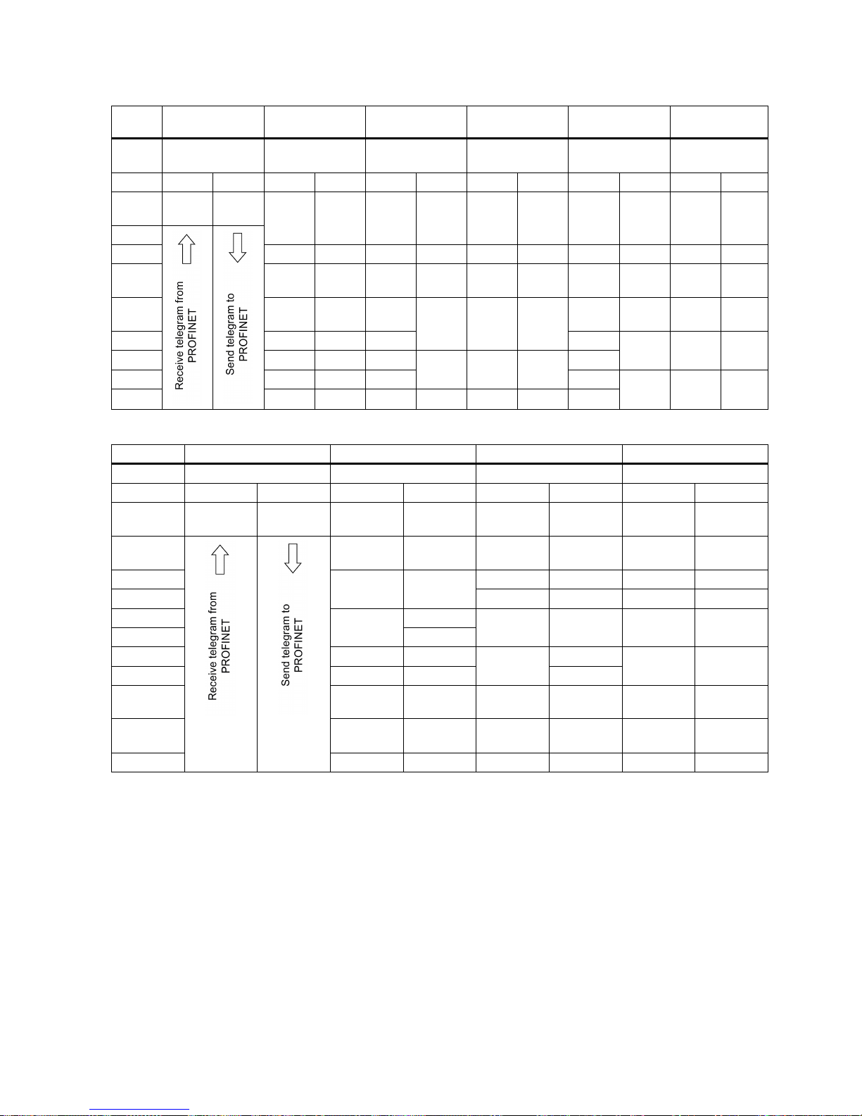
Getting Started
A5E37208904-003, 04/2017
69
Telegrams used for speed control mode
Telegram
1 2 3 5 102
105
Appl.
class
1 1 1, 4 4 1, 4 4
PZD1
STW1
ZSW1
STW1
ZSW1
STW1
ZSW1
STW1
ZSW1
STW1
ZSW1
STW1
ZSW1
PZD2 NSOLL
_A
NIST_A NSOLL
_B
NIST_B NSOLL
_B
NIST_B NSOLL
_B
NIST_B NSOLL
_B
NIST_B NSOLL
_B
NIST_
B
PZD3
PZD4
STW2
ZSW2
STW2
ZSW2
STW2
ZSW2
STW2
ZSW2
STW2
ZSW2
PZD5 G1_STW G1_ZSW G1_STW G1_ZSW MOMR
ED
MELDW MOMR
ED
MELD
W
PZD6 G1_XIS
T1
XERR G1_XIS
T1
G1_STW G1_ZSW G1_STW G1_ZS
W
PZD7
G1_XIS
T1
XERR G1_XI
ST1
PZD8
G1_XIS
T2
KPC G1_XIS
T2
PZD9
G1_XIS
T2
KPC G1_XI
ST2
PZD10
Telegrams used for basic positioner control mode
Telegram
7 9 110
111
Appl. class
3 3 3
3
PZD1
STW1
ZSW1
STW1
ZSW1
STW1
ZSW1
STW1
ZSW1
PZD2 SATZANW AKTSATZ SATZANW AKTSATZ SATZANW AKTSATZ POS_STW1 POS_ZSW
1
PZD3
STW2 ZSW2 POS_STW POS_ZSW POS_STW
2
POS_ZSW
2
PZD4
MDI_
TARPOS
XIST_A
STW2
ZSW2
STW2
ZSW2
PZD5
OVERRIDE
MELDW
OVERRIDE
MELDW
PZD6
MDI_
VELOCITY
MDI_TAR
POS
XIST_A MDI_TAR
POS
XIST_A
PZD7
PZD8
MDI_ACC
MDI_VELO
CITY
MDI_VELO
CITY
NIST_B
PZD9
MDI_DEC
PZD10 MDI_MOD MDI_ACC MDI_ACC FAULT_CO
DE
PZD11 MDI_DEC MDI_DEC WARN_CO
DE
PZD12
MDI_MODE
user 1)
user 2)
1)
User-defined receive word
2)
User-defined send word
Page 70
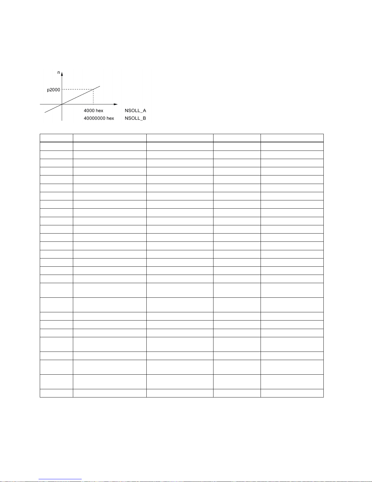
Getting Started
70 A5E37208904-003, 04/2017
6.2
I/O data signals
Parameters p200x apply as reference variables (telegram contents = 4000 hex or 40000000 hex in the case of double words
if the input variable has the value p200x).
The following table provides an overview of the I/O data used in the telegram.
Signal
Description
Receive word/send word
Data type
Scaling
STW1 Control word 1 Receive word U16 -
STW2
Control word 2
Receive word
U16
-
ZSW1
Status word 1
Send word
U16
-
ZSW2
Status word 2
Send word
U16 - NSOLL_A
Speed setpoint A (16 bit)
Receive word
I16
4000 hex ≙ p2000
NSOLL_B
Speed setpoint B (32 bit)
Receive word
I32
40000000 hex ≙ p2000
NIST_A
Speed actual value A (16 bit)
Send word
I16
4000 hex ≙ p2000
NIST_B
Speed actual value B (32 bit)
Send word
I32
40000000 hex ≙ p2000
G1_STW
Encoder 1 control word
Receive word
U16
-
G1_ZSW
Encoder 1 status word
Send word
U16
-
G1_XIST1
Encoder 1 actual position 1
Send word
U32
-
G1_XIST2
Encoder 1 actual position 2
Send word
U32 - MOMRED
Torque reduction
Receive word
I16
4000 hex ≙ p2003
MELDW
Message word
Send word
U16
-
KPC
Position controller gain factor
Receive word
I32
-
XERR
Position deviation
Receive word
I32 - AKTSATZ
Position selected block
Send word
U16
-
MDI_TAR
POS
MDI position Receive word I32 1 hex ≙ 1 LU
MDI_VELO
CITY
MDI velocity Receive word I32 1 hex ≙ 1000 LU/min
MDI_ACC MDI acceleration override Receive word I16 4000 hex ≙ 100%
MDI_DEC
MDI deceleration override
Receive word
I16
4000 hex ≙ 100%
XIST_A
Position actual value A
Send word
I32
1 hex ≙ 1 LU
OVERRIDE
1)
Position velocity override Receive word I16 4000 hex ≙ 100%
MDI_MODE
Position MDI mode
Receive word
U16
-
FAULT_CO
DE
Fault code Send word U16 -
WARN_CO
DE
Alarm code Send word U16 -
POS_ZSW
Position status word
Send word
U16
-
Page 71

Getting Started
A5E37208904-003, 04/2017
71
Signal
Description
Receive word/send word
Data type
Scaling
user User-defined receive word
(p29150):
• 0: No function
• 1: Additional torque
(0x4000 = p2003)
• 2: Additional speed
(0x4000 = p2000)
Receive word I16 -
user User-defined send word
(p29151):
• 0: No function
• 1: Actual torque (0x4000 =
p2003)
• 2: Actual absolute current
(0x4000 = p2002)
•
3: DI status
Send word I16 -
1)
Make sure that signal OVERRIDE is set to a value from 0 to 32767.
6.3
Control word definition
6.3.1
STW1 control word (for telegrams 1, 2, 3, 5)
Note
When p29108.0 = 0, STW1.11 is disabled.
Note
When telegram 5 is used, STW1.4, STW1.5, and STW1.6 are disabl
ed.
Note
STW1.10 must be set to 1 to allow the PLC to control the drive.
Signal
Description
STW1.0
= ON (pulses can be enabled)
0 = OFF1 (braking with ramp-function generator, then pulse suppression and ready for switching on)
STW1.1 1 = No OFF2 (enable is possible)
0 = OFF2 (immediate pulse suppression and switching on inhibited)
STW1.2 1 = No OFF3 (enable is possible)
0 = OFF3 (braking with the OFF3 ramp p1135, then pulse suppression and switching on inhibited)
STW1.3 1 = Enable operation (pulses can be enabled)
0 = Inhibit operation (suppress pulses)
STW1.4 1 = Operating condition (the ramp-function generator can be enabled)
0 = Inhibit ramp-function generator (set the ramp-function generator output to zero)
STW1.5 1 = Continue ramp-function generator
0 = Freeze ramp-function generator (freeze the ramp-function generator output)
STW1.6 1 = Enable setpoint
0 = Inhibit setpoint (set the ramp-function generator input to zero)
STW1.7
= 1. Acknowledge faults
STW1.8
Reserved
STW1.9
Reserved
STW1.10
1 = Control via PLC
Page 72

Getting Started
72 A5E37208904-003, 04/2017
Signal
Description
STW1.11
1 = Setpoint inversion
STW1.12
Reserved
STW1.13
Reserved
STW1.14
Reserved
STW1.15
Reserved
6.3.2
STW2 control word (for telegrams 2, 3, 5)
Signal
Description
STW2.0 Reserved
STW2.1
Reserved
STW2.2
Reserved
STW2.3
Reserved
STW2.4
Reserved
STW2.5
Reserved
STW2.6
Reserved
STW2.7
Reserved
STW2.8
1 = Traverse to fixed endstop
STW2.9
Reserved
STW2.10
Reserved
STW2.11
Reserved
STW2.12
Master sign-of-life, bit 0
STW2.13
Master sign-of-life, bit 1
STW2.14
Master sign-of-life, bit 2
STW2.15
Master sign-of-life, bit 3
6.3.3
STW1 control word (for telegrams 102, 105)
Note
When telegram 105 is used, STW1.4, STW1.5, and
STW1.6 are disabled.
Note
STW1.10 must be set to 1 to allow PLC to control the drive.
Signal
Description
STW1.0
= ON (pulses can be enabled)
0 = OFF1 (braking with ramp-function generator, then pulse suppression and ready for switching on)
STW1.1 1 = No OFF2 (enable is possible)
0 = OFF2 (immediate pulse suppression and switching on inhibited)
STW1.2 1 = No OFF3 (enable is possible)
0 = OFF3 (braking with the OFF3 ramp p1135, then pulse suppression and switching on inhibited)
STW1.3 1 = Enable operation (pulses can be enabled)
0 = Inhibit operation (suppress pulses)
STW1.4 1 = Operating condition (the ramp-function generator can be enabled)
0 = Inhibit ramp-function generator (set the ramp-function generator output to zero)
STW1.5 1 = Continue ramp-function generator
0 = Freeze ramp-function generator (freeze the ramp-function generator output)
Page 73

Getting Started
A5E37208904-003, 04/2017
73
Signal
Description
STW1.6 1 = Enable setpoint
0 = Inhibit setpoint (set the ramp-function generator input to zero)
STW1.7
= 1. Acknowledge faults
STW1.8
Reserved
STW1.9
Reserved
STW1.10
1 = Control via PLC
STW1.11
1 = Ramp-function generator active
STW1.12
1 = Unconditionally open the holding brake
STW1.13 Reserved
STW1.14
Reserved
STW1.15 Reserved
6.3.4
STW2 control word (for telegrams 102, 105)
Note
When p29108.0 = 0, STW2.4 is disabled.
Signal
Description
STW2.0
Reserved
STW2.1
Reserved
STW2.2 Reserved
STW2.3
Reserved
STW2.4
1 = Bypass ramp-function generator
STW2.5
Reserved
STW2.6
1 = Integrator inhibit, speed controller
STW2.7
Reserved
STW2.8
1 = Traverse to fixed endstop
STW2.9
Reserved
STW2.10
Reserved
STW2.11
Reserved
STW2.12
Master sign-of-life, bit 0
STW2.13
Master sign-of-life, bit 1
STW2.14
Master sign-of-life, bit 2
STW2.15
Master sign-of-life, bit 3
Page 74

Getting Started
74 A5E37208904-003, 04/2017
6.3.5
STW1 control word (for telegrams 7, 9, 110, 111)
Note
STW1.10 must be set to 1 to allow the PLC to control the drive.
Signal
Description
STW1.0
= ON (pulses can be enabled)
0 = OFF1 (braking with ramp-function generator, then pulse suppression and ready for switching on)
STW1.1 1 = No OFF2 (enable is possible)
0 = OFF2 (immediate pulse suppression and switching on inhibited)
STW1.2 1 = No OFF3 (enable is possible)
0 = OFF3 (braking with the OFF3 ramp p1135, then pulse suppression and switching on inhibited)
STW1.3 1 = Enable operation (pulses can be enabled)
0 = Inhibit operation (suppress pulses)
STW1.4 1 = Do not reject traversing task
0 = Reject traversing task (ramp-down with the maximum deceleration)
STW1.5 1 = No intermediate stop
0 = Intermediate stop
STW1.6
= Activate traversing task
STW1.7
= Acknowledge faults
STW1.8
1 = Jog 1 signal source
STW1.9
1 = Jog 2 signal source
STW1.10
1 = Control via PLC
STW1.11 1 = Start referencing
0 = Stop referencing
STW1.12
Reserved
STW1.13
= External block change
STW1.14
Reserved
STW1.15
Reserved
6.3.6
STW2 control word (for telegrams 9, 110, 111)
Signal
Description
STW2.0
Reserved
STW2.1
Reserved
STW2.2
Reserved
STW2.3
Reserved
STW2.4 Reserved
STW2.5
Reserved
STW2.6
Reserved
STW2.7
Reserved
STW2.8
1 = Traverse to fixed endstop
STW2.9
Reserved
STW2.10
Reserved
STW2.11
Reserved
STW2.12
Master sign-of-life, bit 0
STW2.13
Master sign-of-life, bit 1
Page 75
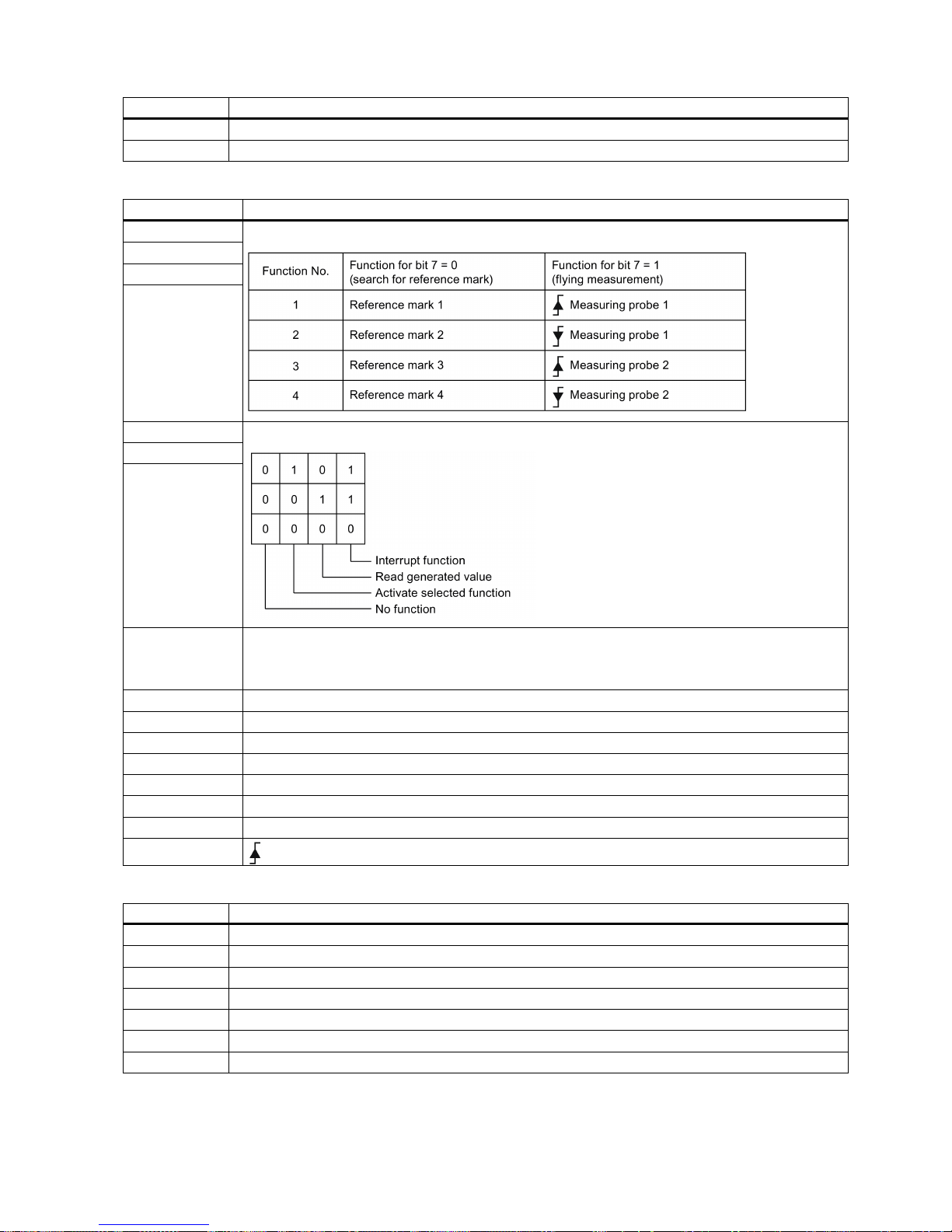
Getting Started
A5E37208904-003, 04/2017
75
Signal
Description
STW2.14
Master sign-of-life, bit 2
STW2.15
Master sign-of-life, bit 3
6.3.7
G1_STW encoder 1 control word
Signal
Description
G1_STW.0
Selects the function to be activate (with bit value = 1)
G1_STW.1
G1_STW.2
G1_STW.3
G1_STW.4
Start/stop/read selected function
G1_STW.5
G1_STW.6
G1_STW.7 Mode of the function to be activated
1 = Flying measurement
0 = Search for reference mark
G1_STW.8
Reserved
G1_STW.9
Reserved
G1_STW.10 Reserved
G1_STW.11
Reserved
G1_STW.12
Reserved
G1_STW.13
1 = Request value cyclic transfer of the absolute position value in Gn_XIST2
G1_STW.14
1 = Request parking encoder
G1_STW.15
= Acknowledge encoder fault
6.3.8
SATZANW control word
Signal
Description
SATZANW.0
1 = Traversing block selection, bit 0
SATZANW.1
1 = Traversing block selection, bit 1
SATZANW.2
1 = Traversing block selection, bit 2
SATZANW.3
1 = Traversing block selection, bit 3
SATZANW.4
1 = Traversing block selection, bit 4
SATZANW.5
1 = Traversing block selection, bit 5
SATZANW.6
Reserved
Page 76

Getting Started
76 A5E37208904-003, 04/2017
Signal
Description
SATZANW.7
Reserved
SATZANW.8
Reserved
SATZANW.9
Reserved
SATZANW.10
Reserved
SATZANW.11
Reserved
SATZANW.12
Reserved
SATZANW.13
Reserved
SATZANW.14
Reserved
SATZANW.15 1 = Activate MDI
0 = Deactivate MDI
6.3.9
MDI_MOD control word
Signal
Description
MDI_MOD.0 1 = Absolute positioning is selected
0 = Relative positioning is selected
MDI_MOD.1
0 = Absolute positioning through the shortest distance
1 = Absolute positioning in the positive direction
2 = Absolute positioning in the negative direction
3 = Absolute positioning through the shortest distance
MDI_MOD.2
MDI_MOD.3
Reserved
MDI_MOD.4
Reserved
MDI_MOD.5
Reserved
MDI_MOD.6
Reserved
MDI_MOD.7
Reserved
MDI_MOD.8
Reserved
MDI_MOD.9
Reserved
MDI_MOD.10 Reserved
MDI_MOD.11
Reserved
MDI_MOD.12 Reserved
MDI_MOD.13
Reserved
MDI_MOD.14
Reserved
MDI_MOD.15
Reserved
6.3.10
POS_STW control word
Signal
Description
POS_STW.0 1 = Tracking mode active
0 = No tracking mode active
POS_STW.1 1 = Set reference point
0 = Do not set reference point
POS_STW.2
1 = Reference cam active
POS_STW.3
Reserved
POS_STW.4
Reserved
POS_STW.5 1 = Jogging, incremental active
0 = Jogging, velocity active
POS_STW.6
Reserved
POS_STW.7
Reserved
Page 77

Getting Started
A5E37208904-003, 04/2017
77
Signal
Description
POS_STW.8
Reserved
POS_STW.9
Reserved
POS_STW.10
Reserved
POS_STW.11
Reserved
POS_STW.12
Reserved
POS_STW.13
Reserved
POS_STW.14
Reserved
POS_STW.15
Reserved
Note
If the tracking mode is activated, the position setpoint follows the actual position value, i.e. position setpoint = actual position
value.
6.3.11
POS_STW1 positioning control word
Signal
Description
POS_STW1.0
Traversing block selection, bit 0
POS_STW1.1
Traversing block selection, bit 1
POS_STW1.2
Traversing block selection, bit 2
POS_STW1.3
Traversing block selection, bit 3
POS_STW1.4
Traversing block selection, bit 4
POS_STW1.5
Traversing block selection, bit 5
POS_STW1.6
Reserved
POS_STW1.7
Reserved
POS_STW1.8 1 = Absolute positioning is selected
0 = Relative positioning is selected
POS_STW1.9
0 = Absolute positioning through the shortest distance
1 = Absolute positioning/MDI direction selection, positive
2 = Absolute positioning/MDI direction selection, negative
3 = Absolute positioning through the shortest distance
POS_STW1.10
POS_STW1.11 Reserved
POS_STW1.12 1 = Continuous transfer
0 = Activate MDI block change with
of a traversing task (STW1.6)
POS_STW1.13
Reserved
POS_STW1.14 1 = Signal setting-up selected
0 = Signal positioning selected
POS_STW1.15
1 = MDI selection
6.3.12
POS_STW2 positioning control word
Signal
Description
POS_STW2.0
1 = Tracking mode active
POS_STW2.1
1 = Set reference point
POS_STW2.2 1 = Reference cam active
POS_STW2.3
Reserved
POS_STW2.4
Reserved
Page 78

Getting Started
78 A5E37208904-003, 04/2017
Signal
Description
POS_STW2.5 1 = Jogging, incremental active
0 = Jogging, velocity active
POS_STW2.6
Reserved
POS_STW2.7
Reserved
POS_STW2.8
Reserved
POS_STW2.9 1 = Start the search for reference in the negative direction
0 = Start the search for reference in the positive direction
POS_STW2.10
Reserved
POS_STW2.11
Reserved
POS_STW2.12
Reserved
POS_STW2.13
Reserved
POS_STW2.14 1 = Software limit switch activation
POS_STW2.15
1 = STOP cam active
Note
If the tracking mode is activated, the position setpoint follows the actual position value, i.e. position setpoint = actual position
value.
6.4
Status word definition
6.4.1
ZSW1 status word (for telegrams 1, 2, 3, 5)
Signal
Description
ZSW1.0
1 = Ready for servo on
ZSW1.1
1 = Ready for operation
ZSW1.2
1 = Operation enabled
ZSW1.3 1 = Fault present
ZSW1.4
1 = No coast down active (OFF2 inactive)
ZSW1.5 1 = No fast stop active (OFF3 inactive)
ZSW1.6
1 = Switching on inhibited active
ZSW1.7
1 = Alarm present
ZSW1.8
1 = Speed setpoint - actual value deviation within tolerance t_off
ZSW1.9
1 = Control requested
ZSW1.10
1 = f or n comparison value reached/exceeded
ZSW1.11
0 = I, M, or P limit reached
ZSW1.12
1 = Open the holding brake
ZSW1.13
1 = No motor overtemperature alarm
ZSW1.14 1 = Motor rotates forwards (n_act ≥ 0)
0 = Motor rotates backwards (n_act < 0)
ZSW1.15
1 = No alarm, thermal overload, power unit
6.4.2
ZSW2 status word (for telegram 2, 3, 5)
Signal
Description
ZSW2.0
Reserved
ZSW2.1
Reserved
ZSW2.2
Reserved
Page 79

Getting Started
A5E37208904-003, 04/2017
79
Signal
Description
ZSW2.3
Reserved
ZSW2.4
Reserved
ZSW2.5
1 = Alarm class bit 0
ZSW2.6
1 = Alarm class bit 1
ZSW2.7
Reserved
ZSW2.8
1 = Traverse to fixed endstop
ZSW2.9
Reserved
ZSW2.10
1 = Pulses enabled
ZSW2.11
Reserved
ZSW2.12
Slave sign-of-life, bit 0
ZSW2.13
Slave sign-of-life, bit 1
ZSW2.14
Slave sign-of-life, bit 2
ZSW2.15
Slave sign-of-life, bit 3
6.4.3
ZSW1 status word (for telegrams 102, 105)
Signal
Description
ZSW1.0
1 = Ready for servo on
ZSW1.1
1 = Ready for operation
ZSW1.2
1 = Operation enabled
ZSW1.3
1 = Fault present
ZSW1.4
1 = No coast down active (OFF2 inactive)
ZSW1.5
1 = No fast stop active (OFF3 inactive)
ZSW1.6
1 = Switching on inhibited active
ZSW1.7
1 = Alarm present
ZSW1.8
1 = Speed setpoint - actual value deviation within tolerance t_off
ZSW1.9 1 = Control requested
ZSW1.10
1 = f or n comparison value reached/exceeded
ZSW1.11
1 = Alarm class bit 0
ZSW1.12
1 = Alarm class bit 1
ZSW1.13
Reserved
ZSW1.14
1 = Closed-loop torque control active
ZSW1.15 Reserved
6.4.4
ZSW2 status word (for telegram 102, 105)
Signal
Description
ZSW2.0
Reserved
ZSW2.1
Reserved
ZSW2.2
Reserved
ZSW2.3
Reserved
ZSW2.4
1 = Ramp-function generator inactive
ZSW2.5
1 = Open the holding brake
ZSW2.6 1 = Integrator inhibit, speed controller
ZSW2.7
Reserved
ZSW2.8 1 = Traverse to fixed endstop
ZSW2.9
Reserved
ZSW2.10
Reserved
Page 80

Getting Started
80 A5E37208904-003, 04/2017
Signal
Description
ZSW2.11
Reserved
ZSW2.12
Slave sign-of-life, bit 0
ZSW2.13
Slave sign-of-life, bit 1
ZSW2.14
Slave sign-of-life, bit 2
ZSW2.15
Slave sign-of-life, bit 3
6.4.5
ZSW1 status word (for telegram 7, 9, 110, 111)
Signal
Description
ZSW1.0 1 = Ready for switching on
ZSW1.1
1 = Ready for operation (DC link loaded, pulses blocked)
ZSW1.2
1 = Operation enabled (drive follows n_set)
ZSW1.3
1 = Fault present
ZSW1.4
1 = No coast down active (OFF2 inactive)
ZSW1.5
1 = No fast stop active (OFF3 inactive)
ZSW1.6
1 = Switching on inhibited active
ZSW1.7
1 = Alarm present
ZSW1.8
1 = Following error within tolerance
ZSW1.9
1 = Control requested
ZSW1.10
1 = Target position reached
ZSW1.11
1 = Reference point set
ZSW1.12
= Acknowledgement traversing block activated
ZSW1.13
1 = Setpoint fixed
ZSW1.14
1 = Axis accelerated
ZSW1.15
1 = Axis decelerated
6.4.6
ZSW2 status word (for telegrams 9, 110, 111)
Signal
Description
ZSW2.0
Reserved
ZSW2.1
Reserved
ZSW2.2
Reserved
ZSW2.3
Reserved
ZSW2.4
Reserved
ZSW2.5
1 = Alarm class bit 0
ZSW2.6
1 = Alarm class bit 1
ZSW2.7
Reserved
ZSW2.8
1 = Traverse to fixed endstop
ZSW2.9
Reserved
ZSW2.10
1 = Pulses enabled
ZSW2.11
Reserved
ZSW2.12 Slave sign-of-life, bit 0
ZSW2.13
Slave sign-of-life, bit 1
ZSW2.14 Slave sign-of-life, bit 2
ZSW2.15
Slave sign-of-life, bit 3
Page 81
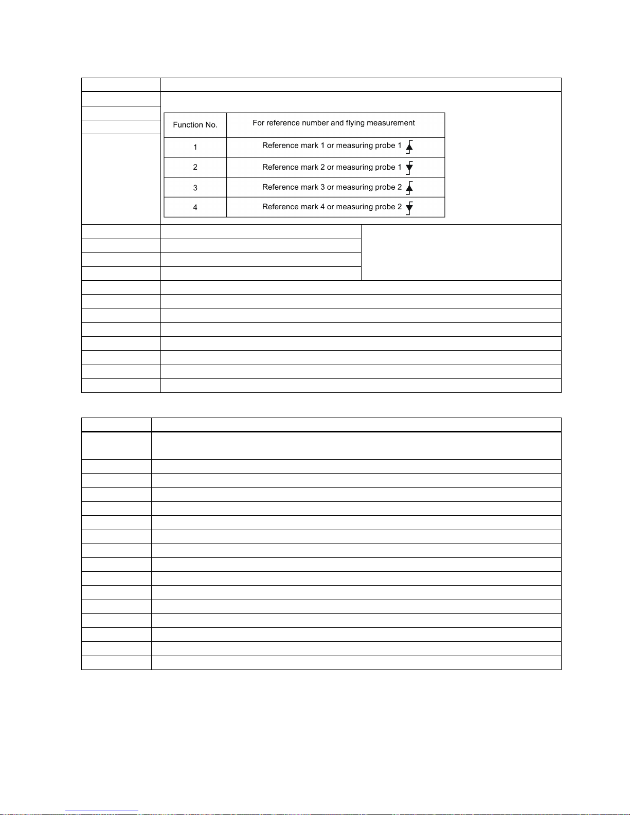
Getting Started
A5E37208904-003, 04/2017
81
6.4.7
G1_ZSW encoder 1 status word
Signal
Description
G1_ZSW.0
Feedback signal of the active function (1 = function active)
G1_ZSW.1
G1_ZSW.2
G1_ZSW.3
G1_ZSW.4
1 = Position actual value from function 1
Generated value in Gn_XIST2 (and can be read)
G1_ZSW.5
1 = Position actual value from function 2
G1_ZSW.6
1 = Position actual value from function 3
G1_ZSW.7
1 = Position actual value from function 4
G1_ZSW.8
Reserved
G1_ZSW.9
Reserved
G1_ZSW.10
Reserved
G1_ZSW.11
1 = Acknowledge encoder fault active
G1_ZSW.12
Reserved (for reference point offset)
G1_ZSW.13
Absolute value is cyclically transferred
G1_ZSW.14
Parking encoder active
G1_ZSW.15
Encoder fault, the fault is in Gn_XIST2
6.4.8
MELDW status word
Signal
Description
MELDW.0 1 = Ramp-up/ramp-down complete
0 = Ramp-function generator active
MELDW.1
1 = Torque utilization [%] < torque threshold value 2
MELDW.2
1 = |n_act| < speed threshold value 3 (p2161)
-MELDW.3
1 = |n_act| ≤ speed threshold value 2
MELDW.4
1 = Vdc_min controller active
MELDW.5
Reserved
MELDW.6
1 = No motor overtemperature alarm
MELDW.7
1 = No alarm, thermal overload, power unit
MELDW.8
1 = Speed setpoint - actual value deviation within tolerance t_on
MELDW.9
Reserved
MELDW.10
Reserved
MELDW.11
1 = Controller enable
MELDW.12
1 = Drive ready
MELDW.13
1 = Pulses enabled
MELDW.14
Reserved
MELDW.15
Reserved
Page 82

Getting Started
82 A5E37208904-003, 04/2017
6.4.9
POS_ZSW1 positioning status word
Signal
Description
POS_ZSW1.0
Active Traversing Block Bit 0 (20)
POS_ZSW1.1
Active Traversing Block Bit 0 (21)
POS_ZSW1.2
Active Traversing Block Bit 0 (22)
POS_ZSW1.3
Active Traversing Block Bit 0 (23)
POS_ZSW1.4
Active Traversing Block Bit 0 (24)
POS_ZSW1.5
Active Traversing Block Bit 0 (25)
POS_ZSW1.6
Reserved
POS_ZSW1.7
Reserved
POS_ZSW1.8
1 = STOP cam minus active
POS_ZSW1.9
1 = STOP cam plus active
POS_ZSW1.10
1 = Jogging active
POS_ZSW1.11
1 = Reference point approach active
POS_ZSW1.12
Reserved
POS_ZSW1.13
1 = Traversing Block active
POS_ZSW1.14
1 = Set-up active
POS_ZSW1.15 1 = MDI active
0 = MDI inactive
6.4.10
POS_ZSW2 positioning status word
Signal
Description
POS_ZSW2.0
1 = Tracking mode active
POS_ZSW2.1
1 = Velocity limiting active
POS_ZSW2.2
1 = Setpoint available
POS_ZSW2.3
Reserved
POS_ZSW2.4
1 = Axis moves forward
POS_ZSW2.5
1 = Axis moves backwards
POS_ZSW2.6
1 = Software limit switch minus reached
POS_ZSW2.7
1 = Software limit switch plus reached
POS_ZSW2.8
1 = Position actual value ≤ cam switching position 1
POS_ZSW2.9
1 = Position actual value ≤ cam switching position 2
POS_ZSW2.10
1 = Direct output 1 via traversing block
POS_ZSW2.11 1 = Direct output 2 via traversing block
POS_ZSW2.12
1 = Fixed stop reached
POS_ZSW2.13
1 = Fixed stop clamping torque reached
POS_ZSW2.14
1 = Travel to fixed stop active
POS_ZSW2.15
1 = Traversing command active
For more information about the PROFINET communication, refer to SINAMICS V90, SIMOTICS S-1FL6 Operating
Instructions.
Page 83
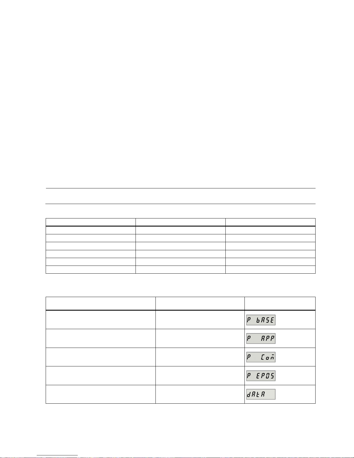
Getting Started
A5E37208904-003, 04/2017
83
7
Parameters
7.1
Overview
The section below lists all the parameters of the SINAMICS V90 PN servo drive.
Parameter number
Numbers prefixed with an "r" indicate that parameter is a read-only parameter.
Numbers prefixed with a "p" indicate that the parameter is an editable parameter.
Effective
Indicates the conditions for making parameterization effective. Two conditions are possible:
● IM (Immediately): Parameter value becomes effective immediately after changing.
● RE (Reset): Parameter value becomes effective after repower-on.
Can be changed
This indicates when the parameter can be changed. Two states are possible:
● U (Run): Can be changed in the "
Running
" state when the drive is in "servo on" state. The "RDY" LED lights up green.
● T (Ready to run): Can be changed in the "
Ready
" state when the drive is in "servo off" state. The "RDY" LED lights up
red.
Note
When judging the state of the drive according to the "RDY" LED, ensure that no faults or alarms exist.
Data type
Date type
Abbreviation
Description
Integer16
I16
16-bit integer
Integer32
I32
32-bit integer
Unsigned8
U8
8-bit unsigned integer
Unsigned16
U16
16-bit unsigned integer
Unsigned32
U32
32-bit unsigned integer
FloatingPoint32 Float 32-bit floating point number
Parameter groups
The SINAMICS V90 PN parameters are divided into the following groups:
Parameter group
Available parameters
Parameter group display on
the BOP
Basic parameters p07xx, p10xx to p16xx, p21xx
Application parameters p29xxx
Communication parameters p09xx, p89xx
Basic positioner parameters p25xx, p26xx
Status monitoring parameters All read-only parameters
Page 84
Getting Started
84 A5E37208904-003, 04/2017
7.2
Parameter list
Editable parameters
The values of the parameters marked with an asterisk (*) may be changed after commissioning. Make sure you back up the
parameters first as required if you desire to replace the motor. The default values of the parameters marked with two
asterisks (**) are motor dependent. They may have different default values when the drive connects to different motors.
Par. No.
Name
Min
Max
Factory
Setting
Unit
Data
type
Effective
Can be
changed
p0748
CU invert digital outputs
- - 0 - U32
IM
T, U
Description: Inverts the signals at the digital outputs.
• Bit 0: inverts signal DO 1
– Bit 0 = 0: not inverted
– Bit 0 = 1: inverted
• Bit 1: inverts signal DO 2
– Bit 1 = 0: not inverted
– Bit 1 = 1: inverted
p0922 PROFIdrive: PZD tele-
gram selection
1 111 105 - U16 IM T
Description: Sets the send and receive telegram.
For speed control mode:
• 1: Standard telegram 1, PZD-2/2
• 2: Standard telegram 2, PZD-4/4
• 3: Standard telegram 3, PZD-5/9
• 5: Standard telegram 5, PZD-9/9
• 102: SIEMENS telegram 102, PZD-6/10
• 105: SIEMENS telegram 105, PZD-10/10
For basic positioner control mode:
• 7: Standard telegram 7, PZD-2/2
• 9: Standard telegram 9, PZD-10/5
• 110: SIEMENS telegram 110, PZD-12/7
•
111: SIEMENS telegram 111, PZD-12/12
p0925 PROFIdrive: Synchro-
nous sign-of-life tolerance
0 65535 1 - U16 IM T, U
Description:
Sets the number of tolerated consecutive sign-of-life errors of the clock-cycle synchronous mas-
ter. The sign-of-life signal is normally received in PZD4 (control word 2) from the master.
p0972
Drive unit reset
0 2 0 - U16
IM
T, U
Description:
Sets the required procedure to execute a hardware reset for the drive unit.
• 0: Inactive
• 1: Hardware reset immediate
•
2: Hardware reset preparation
Danger:
It must be absolutely ensured that the system is in a safe condition.
The memory card/device memory of the Control Unit must not be accessed.
Note:
If value = 1:
Reset is immediately executed and communications interrupted.
If value = 2:
Help to check the reset operation.
Firstly, set p0972 = 2 and then read back. Secondly, set p0972 = 1 (it is possible that this request is possibly
no longer acknowledged). The communication is then interrupted.
After the drive unit has been restarted and communications have been established, read p0972 and check the
following:
p0972 = 0? → The reset was successfully executed.
p0972 > 0? → The reset was not executed.
Page 85
Getting Started
A5E37208904-003, 04/2017
85
Par. No.
Name
Min
Max
Factory
Setting
Unit
Data
type
Effective
Can be
changed
p0977
Save all parameters
0 1 0 - U16
IM
T, U
Description:
Saves all parameters of the drive system to the non-volatile memory.
When saving, only the adjustable parameters intended to be saved are taken into account.
• Value = 0: Inactive
•
Value = 1: Save in non-volatile memory - downloaded at POWER ON
Notice:
The Control Unit power supply may only be powered down after data has been saved (i.e. after data
save has been started, wait until the parameter again has the value 0).
Writing to parameters is inhibited while saving.
p1058
JOG 1 speed setpoint
0.00
210000.000
100.00
rpm
Float
IM
T
Description:
Sets the speed/velocity for JOG 1. Jogging is level-triggered and allows the motor to be incre-
mentally moved.
Note: The parameter values displayed on the BOP are integers.
p1082 * Maximum speed 0.000 210000.000 1500.000 rpm Float IM T
Description: Sets the highest possible speed.
Notice: After the value has been modified, no further parameter modifications can be made.
Note:
The parameter values displayed on the BOP are integers.
The parameter applies for both motor directions.
The parameter has a limiting effect and is the reference quantity for all ramp-up and ramp-down times (e.g.
down ramps, ramp-function generator and motor potentiometer).
The range of the parameter is different when connect with different motors.
p1083 * Speed limit in positive
direction of rotation
0.000 210000.000 210000.
000
rpm Float IM T, U
Description: Sets the maximum speed for the positive direction.
Note: The parameter values displayed on the BOP are integers.
p1086 * Speed limit in negative
direction of rotation
-210000.000 0.000 -
210000.
000
rpm Float IM T, U
Description: Sets the speed limit for the negative direction.
Note: The parameter values displayed on the BOP are integers.
p1115 Ramp-function generator
selection
0 1 0 - I16 IM T
Description: Sets the ramp-function generator type.
Note: Another ramp-function generator type can only be selected when the motor is at a standstill.
p1120 Ramp-function generator
ramp-up time
0.000 999999.000 1 s Float IM T, U
Description:
The ramp-function generator ramps-up the speed setpoint from standstill (setpoint = 0) up to the
maximum speed (p1082) in this time.
Dependency: Refer to p1082
p1121 Ramp-function generator
ramp-down time
0.000 999999.000 1 s Float IM T, U
Description:
Sets the ramp-down time for the ramp-function generator.
The ramp-function generator ramps-down the speed setpoint from the maximum speed (p1082) down to
standstill (setpoint = 0) in this time.
Further, the ramp-down time is always effective for OFF1.
Dependency: Refer to p1082
Page 86
Getting Started
86 A5E37208904-003, 04/2017
Par. No.
Name
Min
Max
Factory
Setting
Unit
Data
type
Effective
Can be
changed
p1130 Ramp-function generator
initial rounding-off time
0.000 30.000 0.000 s Float IM T, U
Description:
Sets the initial rounding-off time for the extended ramp generator. The value applies to ramp-up
and ramp-down.
Note: Rounding-off times avoid an abrupt response and prevent damage to the mechanical system.
p1131 Ramp-function generator
final rounding-off time
0.000 30.000 0.000 s Float IM T, U
Description:
Sets the final rounding-off time for the extended ramp generator. The value applies to ramp-up
and ramp-down.
Note: Rounding-off times avoid an abrupt response and prevent damage to the mechanical system.
p1135
OFF3 ramp-down time
0
600 0 s
Float
IM
T, U
Description: Sets the ramp-down time from the maximum speed down to zero speed for the OFF3 command.
Note: This time can be exceeded if the DC link voltage reaches its maximum value.
p1215 * Motor holding brake con-
figuration
0 2 0 - I16 IM T
Description: Sets the holding brake configuration.
Dependency: Refer to p1216, p1217, p1226, p1227, p1228
Caution:
For the setting p1215 = 0, if a brake is used, it remains closed. If the motor moves, this will destroy
the brake.
Notice:
If p1215 was set to 1, then when the pulses are suppressed, the brake is closed even if the motor is
still rotating.
Note: The parameter can only be set to zero when the pulses are inhibited.
p1216 * Motor holding brake
opening time
0 10000 100 ms Float IM T, U
Description:
Sets the time to open the motor holding brake.
After controlling the holding brake (opens), the speed/velocity setpoint remains at zero for this time. After this,
the speed/velocity setpoint is enabled.
Dependency: Refer to p1215, p1217
Note:
For a motor with integrated brake, this time is pre-assigned the value saved in the motor.
For p1216 = 0 ms, the monitoring and the message A7931 "Brake does not open" are deactivated.
p1217 * Motor holding brake clos-
ing time
0 10000 100 ms Float IM T, U
Description:
Sets the time to apply the motor holding brake.
After OFF1 or OFF3 and the holding brake is controlled (the brake closes), then the drive remains closed-loop
controlled for this time stationary with a speed setpoint/velocity setpoint of zero. The pulses are suppressed
when the time expires.
Dependency: Refer to p1215, p1216
Note:
For a motor with integrated brake, this time is pre-assigned the value saved in the motor.
For p1217 = 0 ms, the monitoring and the message A07932 "Brake does not close" are deactivated.
p1226 Threshold for zero speed
detection
0.00 210000.00 20.00 rpm Float IM T, U
Description:
Sets the speed threshold for the standstill identification.
Acts on the actual value and setpoint monitoring. When braking with OFF1 or OFF3, when the threshold is
undershot, standstill is identified.
The following applies when the brake control is activated:
When the threshold is undershot, the brake control is started and the system waits for the brake closing time
in p1217. The pulses are then suppressed.
If the brake control is not activated, the following applies:
When the threshold is undershot, the pulses are suppressed and the drive coasts down.
Page 87
Getting Started
A5E37208904-003, 04/2017
87
Par. No.
Name
Min
Max
Factory
Setting
Unit
Data
type
Effective
Can be
changed
Dependency: Refer to p1215, p1216, p1217, p1227
Notice:
For reasons relating to the compatibility to earlier firmware versions, a parameter value of zero in
indices 1 to 31 is overwritten with the parameter value in index 0 when the drive boots.
Note:
Standstill is identified in the following cases:
- The speed actual value falls below the speed threshold in p1226 and the time started after this in p1228 has
expired.
- The speed setpoint falls below the speed threshold in p1226 and the time started after this in p1227 has
expired.
The actual value sensing is subject to measuring noise. For this reason, standstill cannot be detected if the
speed threshold is too low.
p1227 Zero speed detection
monitoring time
0.000 300.000 300.000 s Float IM T, U
Description:
Sets the monitoring time for the standstill identification.
When braking with OFF1 or OFF3, standstill is identified after this time has expired, after the setpoint speed
has fallen below p1226.
After this, the brake control is started, the system waits for the closing time in p1217 and then the pulses are
suppressed.
Dependency: Refer to p1215, p1216, p1217, p1226
Notice:
The setpoint is not equal to zero dependent on the selected value. This can therefore cause the moni-
toring time in p1227 to be exceeded. In this case, for a driven motor, the pulses are not suppressed..
Note:
Standstill is identified in the following cases:
- The speed actual value falls below the speed threshold in p1226 and the time started after this in p1228 has
expired.
- The speed setpoint falls below the speed threshold in p1226 and the time started after this in p1227 has
expired.
For p1227 = 300.000 s, the following applies:
Monitoring is de-activated.
For p1227 = 0.000 s, the following applies:
With OFF1 or OFF3 and a ramp-down time = 0, the pulses are immediately suppressed and the motor
"coasts" down.
p1228 Pulse suppression delay
time
0.000 299.000 0.000 s Float IM T, U
Description:
Sets the delay time for pulse suppression. After OFF1 or OFF3, the pulses are canceled, if at
least one of the following conditions is fulfilled:
- The speed actual value falls below the threshold in p1226 and the time started after this in p1228 has expired.
- The speed setpoint falls below the threshold in p1226 and the time started after this in p1227 has expired.
Dependency: Refer to p1226, p1227
Notice:
When the motor holding brake is activated, pulse cancellation is additionally delayed by the brake
closing time (p1217).
p1414 Speed setpoint filter acti-
vation
- - 0000
bin
- U16 IM T, U
Description:
Setting for activating/de-activating the speed setpoint filter.
• Bit 0: Activate filter 1
– Bit 0 = 0: Deactivated
– Bit 0 = 1: Activated
• Bit 1: Activate filter 2
– Bit 1 = 0: Deactivated
– Bit 1 = 1: Activated
Page 88
Getting Started
88 A5E37208904-003, 04/2017
Par. No.
Name
Min
Max
Factory
Setting
Unit
Data
type
Effective
Can be
changed
Dependency: The individual speed setpoint filters are parameterized as of p1415.
Note: The drive unit displays the value in hex format. To know the logic (high/low) assignment to each bit, you
must convert the hex number to the binary number, for example, FF (hex) = 11111111 (bin).
p1415 Speed setpoint filter 1
type
0 2 0 - I16 IM T, U
Description: Sets the type for speed setpoint filter 1.
Dependency:
PT1 low pass: p1416
PT2 low pass: p1417, p1418
General filter: p1417 ... p1420
p1416 Speed setpoint filter 1
time constant
0.00 5000.00 0.00 ms Float IM T, U
Description: Sets the time constant for the speed setpoint filter 1 (PT1).
Dependency: Refer to p1414, p1415
Note: This parameter is only effective if the filter is set as a PT1 low pass.
p1417 Speed setpoint filter 1
denominator natural fre-
quency
0.5 16000.0 1999.0 Hz Float IM T, U
Description: Sets the denominator natural frequency for speed setpoint filter 1(PT2, general filter).
Dependency:
Refer to p1414, p1415
Note:
This parameter is only effective if the speed filter is parameterized as a PT2 low pass or as general
filter.
The filter is only effective if the natural frequency is less than half of the sampling frequency.
p1418 Speed setpoint filter 1
denominator damping
0.001 10.000 0.700 - Float IM T, U
Description: Sets the denominator damping for speed setpoint filter 1 (PT2, general filter).
Dependency: Refer to p1414, p1415
Note:
This parameter is only effective if the speed filter is parameterized as a PT2 low pass or as general
filter.
p1419 Speed setpoint filter 1
numerator natural fre-
quency
0.5 16000.0 1999.0 Hz Float IM T, U
Description: Sets the numerator natural frequency for speed setpoint filter 1 (general filter).
Dependency: Refer to p1414, p1415
Note:
This parameter is
only effective if the speed filter is set as a general filter. The filter is only effective if the
natural frequency is less than half of the sampling frequency.
p1420 Speed setpoint filter 1
numerator damping
0.001 10.000 0.700 - Float IM T, U
Description: Sets the numerator damping for speed setpoint filter 1 (general filter).
Dependency: Refer to p1414, p1415
Note:
This parameter is only effective if the speed filter is set as a general filter.
p1421 Speed setpoint filter 2
type
0 2 0 - I16 IM T, U
Description: Sets the type for speed setpoint filter 2.
Dependency:
PT1 low pass: p1422
PT2 low pass: p1423, p1424
General filter: p1423 ... p1426
Page 89
Getting Started
A5E37208904-003, 04/2017
89
Par. No.
Name
Min
Max
Factory
Setting
Unit
Data
type
Effective
Can be
changed
p1422 Speed setpoint filter 2
time constant
0.00 5000.00 0.00 ms Float IM T, U
Description: Sets the time constant for the speed setpoint filter 2 (PT1).
Dependency:
Refer to p1414, p1421
Note: This parameter is only effective if the speed filter is set as a PT1 low pass.
p1423 Speed setpoint filter 2
denominator natural fre-
quency
0.5 16000.0 1999.0 Hz Float IM T, U
Description: Sets the denominator natural frequency for speed setpoint filter 2 (PT2, general filter).
Dependency: Refer to p1414, p1421
Note:
This parameter is only effective if the speed filter is parameterized as a PT2 low pass or as general
filter.
The filter is only effective if the natural frequency is less than half of the sampling frequency.
p1424 Speed setpoint filter 2
denominator damping
0.001 10.000 0.700 - Float IM T, U
Description: Sets the denominator damping for speed setpoint filter 2 (PT2, general filter).
Dependency: Refer to p1414, p1421
Note:
This parameter is only effective if the speed filter is parameterized as a PT2 low pass or as general
filter.
p1425 Speed setpoint filter 2
numerator natural fre-
quency
0.5 16000.0 1999.0 Hz Float IM T, U
Description: Sets the numerator natural frequency for speed setpoint filter 2 (general filter).
Dependency: Refer to p1414, p1421
Note:
This parameter is only effective if the speed filter is set as a general filter.
The filter is only effective if the natural frequency is less than half of the sampling frequency.
p1426 Speed setpoint filter 2
numerator damping
0.000 10.000 0.700 - Float IM T, U
Description: Sets the numerator damping for speed setpoint filter 2 (general filter).
Dependency: Refer to p1414, p1421
Note: This parameter is only effective if the speed filter is set as a general filter.
p1441 Actual speed smoothing
time
0.00 50.00 0.00 ms Float IM T, U
Description: Sets the smoothing time constant (PT1) for the speed actual value.
Note:
The speed actual value should be smoothed for increment encoders with a low pulse number.
After this parameter has been changed, we recommend that the speed controller is adapted and/or the speed
controller settings checked Kp (p29120) and Tn (p29121).
p1520 * Torque limit upper -1000000.00 20000000.00 0.00 Nm Float IM T, U
Description: Sets the fixed upper torque limit.
Danger:
Negative values when setting the upper torque limit (p1520 < 0) can result in the motor accelerating
in an uncontrollable fashion.
Notice:
The maximum value depends on the maximum torque of the connected motor.
p1521 *
Torque limit lower
-20000000.00
1000000.00
0.00
Nm
Float
IM
T, U
Description: Sets the fixed lower torque limit.
Danger:
Positive values when setting the lower torque limit (p1521 > 0) can result in the motor accelerating in
an uncontrollable fashion.
Notice: The maximum value depends on the maximum torque of the connected motor.
Page 90
Getting Started
90 A5E37208904-003, 04/2017
Par. No.
Name
Min
Max
Factory
Setting
Unit
Data
type
Effective
Can be
changed
p1656 * Activates current setpoint
filter
- - 0001
bin
- U16 IM T, U
Description:
Setting for activating/de-activating the current setpoint filter.
• Bit 0: Activate filter 1
– Bit 0 = 0: Deactivated
– Bit 0 = 1: Activated
• Bit 1: Activate filter 2
– Bit 1 = 0: Deactivated
– Bit 1 = 1: Activated
• Bit 2: Activate filter 3
– Bit 2 = 0: Deactivated
– Bit 2 = 1: Activated
• Bit 3: Activate filter 4
– Bit 3 = 0: Deactivated
– Bit 3= 1: Activated
Dependency: The individual current setpoint filters are parameterized as of p1658.
Note:
If not all of the fil
ters are required, then the filters should be used consecutively starting from filter 1. The
drive unit displays the value in hex format. To know the logic (high/low) assignment to each bit, you must
convert the hex number to the binary number, for example, FF (hex) = 11111111 (bin).
p1658 * Current setpoint filter 1
denominator natural fre-
quency
0.5 16000.0 1999.0 Hz Float IM T, U
Description: Sets the denominator natural frequency for current setpoint filter 1 (PT2, general filter).
Dependency: The current setpoint filter 1 is activated via p1656.0 and parameterized via p1658 ... p1659.
p1659 * Current setpoint filter 1
denominator damping
0.001 10.000 0.700 - Float IM T, U
Description: Sets the denominator damping for current setpoint filter 1.
Dependency: The current setpoint filter 1 is activated via p1656.0 and parameterized via p1658 ... p1659.
p1663 Current setpoint filter 2
denominator natural fre-
quency
0.5 16000.0 1000.0 Hz Float IM T, U
Description: Sets the denominator natural frequency for current setpoint filter 2 (PT2, general filter).
Dependency: Current setpoint filter 2 is activated via p1656.1 and parameterized via p1663 ... p1666.
p1664 Current setpoint filter 2
denominator damping
0.001 10.000 0.300 - Float IM T, U
Description: Sets the denominator damping for current setpoint filter 2.
Dependency: Current setpoint filter 2 is activated via p1656.1 and parameterized via p1663 ... p1666.
p1665 Current setpoint filter 2
numerator natural fre-
quency
0.5 16000.0 1000.0 Hz Float IM T, U
Description: Sets the numerator natural frequency for current setpoint filter 2 (general filter).
Dependency: Current setpoint filter 2 is activated via p1656.1 and parameterized via p1662 ... p1666.
p1666
Current setpoint filter 2
numerator damping
0.000 10.000 0.010 - Float IM T, U
Description: Sets the numerator damping for current setpoint filter 2.
Dependency: Current setpoint filter 2 is activated via p1656.1 and parameterized via p1663 ... p1666.
Page 91
Getting Started
A5E37208904-003, 04/2017
91
Par. No.
Name
Min
Max
Factory
Setting
Unit
Data
type
Effective
Can be
changed
p1668 Current setpoint filter 3
denominator natural frequency
0.5 16000.0 1000.0 Hz Float IM T, U
Description: Sets the denominator natural frequency for current setpoint filter 3 (PT2, general filter).
Dependency: Current setpoint filter 3 is activated via p1656.2 and parameterized via p1668 ... p1671.
p1669 Current setpoint filter 3
denominator damping
0.001 10.000 0.300 - Float IM T, U
Description: Sets the denominator damping for current setpoint filter 3.
Dependency: Current setpoint filter 3 is activated via p1656.2 and parameterized via p1668 ... p1671.
p1670 Current setpoint filter 3
numerator natural fre-
quency
0.5 16000.0 1000.0 Hz Float IM T, U
Description: Sets the numerator natural frequency for current setpoint filter 3 (general filter).
Dependency: Current setpoint filter 3 is activated via p1656.2 and parameterized via p1668 ... p1671.
p1671 Current setpoint filter 3
numerator damping
0.000 10.000 0.010 - Float IM T, U
Description: Sets the numerator damping for current setpoint filter 3.
Dependency: Current setpoint filter 3 is activated via p1656.2 and parameterized via p1668 ... p1671.
p1673 Current setpoint filter 4
denominator natural fre-
quency
0.5 16000.0 1000.0 Hz Float IM T, U
Description:
Sets the denominator natural frequency for current setpoint filter 4 (PT2, general filter).
Dependency: Current setpoint filter 4 is activated via p1656.3 and parameterized via p1673 ... p1675.
p1674 Current setpoint filter 4
denominator damping
0.001 10.000 0.300 - Float IM T, U
Description: Sets the denominator damping for current setpoint filter 4.
Dependency: Current setpoint filter 4 is activated via p1656.3 and parameterized via p1673 ... p1675.
p1675 Current setpoint filter 4
numerator natural fre-
quency
0.5 16000.0 1000.0 Hz Float IM T, U
Description: Sets the numerator natural frequency for current setpoint filter 4 (general filter).
Dependency: Current setpoint filter 4 is activated via p1656.3 and parameterized via p1673 ... p1675.
p1676 Current setpoint filter 4
numerator damping
0.000 10.000 0.010 - Float IM T, U
Description: Sets the numerator damping for current setpoint filter 4.
Dependency: Current setpoint filter 4 is activated via p1656.3 and parameterized via p1673 ... p1675.
p2000
Reference speed
6.00
210000.00
3000.00
rpm
Float
IM
T
Description:
Sets the reference quantity for speed and frequency.
All speeds or frequencies specified as relative value are referred to this reference quantity.
The reference quantity corresponds to 100% or 4000 hex (word) or 40000000 hex (double word).
Dependency:
Refer to: p2003
p2002 Reference current 0.10 100000.00 100.00 Arms Float IM T
Description
: Sets the reference quantity for currents.
All currents specified as relative value are referred to this reference quantity.
The reference quantity corresponds to 100% or 4000 hex (word) or 4000 0000 hex (double word).
Page 92
Getting Started
92 A5E37208904-003, 04/2017
Par. No.
Name
Min
Max
Factory
Setting
Unit
Data
type
Effective
Can be
changed
Notice:
If various DDS are used with different motor data, then the reference quantities remain the same as
these are not changed over with the DDS. The resulting conversion factor should be taken into account (e.g.
for trace records).
Example:
p2002 = 100 A
Reference quantity 100 A corresponds to 100 %
p2003 Reference torque 0.01 20000000.00 1.00 Nm Float IM T
Description:
Sets the referene quantity for torque.
All torques specified as relative value are referred to this reference quantity.
The reference quantity corresponds to 100% or 4000 hex (word) or 40000000 hex (double word).
p2153
Speed actual value filter
time constant
0
1000000
0
ms
Float
IM
T, U
Description:
Sets the time constant of the PT1 element to smooth the speed/velocity actual value.
The smoothed actual speed/velocity is compared with the threshold values and is only used for messages and
signals.
p2161 *
Speed threshold 3
0.00
210000.00
10.00
rpm
Float
IM
T, U
Description: Sets the speed threshold value for the signal that indicates the axis is stationary.
p2162 *
Hysteresis speed n_act >
n_max
0.00
60000.00
0.00
rpm
Float
IM
T, U
Description: Sets the hysteresis speed (bandwidth) for the signal "n_act > n_max".
Note:
For a negative speed limit, the hysteresis is effective below the limit value and for a positive speed limit above
the limit value.
If significant overshoot occurs in the maximum speed range (for example, due to load shedding), you are
advised to increase the dynamic response of the speed controller (if possible). If this is insufficient, the hysteresis p2162 can be increased, but its value must not be greater than the value calculated by the formula below when the motor maximum speed is sufficiently greater than the maximum speed p1082.
p2162 ≤ 1.05 × motor maximum speed - maximum speed (p1082)
The range of the parameter is different when connect with different motors.
p2175 *
Motor blocked speed
threshold
0.00
210000.00
210000.
00
rpm
Float
IM
T, U
Description: Sets the speed threshold for the message "Motor blocked".
Dependency: Refer to p2177.
p2177 *
Motor blocked delay time
0.000
65.000
0.500
s
Float
IM
T, U
Description: Sets the delay time for the message "Motor blocked".
Dependency: Refer to p2175.
p2525
LR encoder adjustment
offset
0
429496729
5
0
LU
U32
IM
T
Description: Position offset when adjusting the absolute encoder.
Note: The position offset is only relevant for absolute encoders. The drive determines the value when adjusting the absolute encoder and the user should not change it.
p2533
LR position setpoint filter
time constant
0.00
1000.00
0.00
ms
Float
IM
T, U
Description: Sets the time constant for the position setpoint filter (PT1).
Note:
The effective Kv factor (position loop gain) is reduced with the filter.
This allows a softer control behavior with improved tolerance with respect to noise/disturbances.
Applications:
- Reduces the pre-control dynamic response.
- Jerk limiting.
Page 93
Getting Started
A5E37208904-003, 04/2017
93
Par. No.
Name
Min
Max
Factory
Setting
Unit
Data
type
Effective
Can be
changed
p2542 * LR standstill window 0 2147483647 1000 LU U32 IM T, U
Description:
Sets the standstill window for the standstill monitoring function.
After the standstill monitoring time expires, it is cyclically checked whether the difference between the setpoint
and actual position is located within the standstill window and, if required, an appropriate fault is output.
Value = 0: The standstill monitoring is deactivated.
Dependency: Refer to: p2543, p2544, and F07450
Note:
The following applies for the setting of the standstill and positioning window:
Standstill window (p2542) ≥ positioning window (p2544)
p2543 * LR standstill monitoring
time
0.00 100000.00 200.00 ms Float IM T, U
Description:
Sets the standstill monitoring time for the standstill monitoring function.
After the standstill monitoring time expires, it is cyclically checked whether the difference between the setpoint
and actual position is located within the standstill window and, if required, an appropriate fault is output.
Dependency: Refer to: p2542, p2545, and F07450
Note:
The following applies for the setting of the standstill and positioning monitoring time:
Standstill monitoring time (p2543) ≤ positioning monitoring time (p2545)
p2544 * LR positioning window 0 2147483647 40 LU U32 IM T, U
Description:
Sets the positioning window for the positioning monitoring function.
After the positioning monitoring time expires, it is checked once as to whether the difference between the
setpoint and actual position lies within the positioning window and if required an appropriate fault is output.
Value = 0: The positioning monitoring function is de-activated.
Dependency: Refer to: p2542, p2545, and F07451
Note:
The following applies for the setting of the standstill and positioning window:
Standstill window (p2542) ≥ positioning window (p2544)
p2545 * LR positioning monitoring
time
0.00 100000.00 1000.00 ms Float IM T, U
Description:
Sets the positioning monitoring time for the positioning monitoring.
After the positioning monitoring time expires, it is checked once as to whether the difference between the
setpoint and actual position lies within the positioning window and if required an appropriate fault is output.
Dependency:
The range of p2545 depends on p2543.
Refer to: p2543, p2544, and F07451
Note:
The following applies for the setting of the standstill and positioning monitoring time:
Standstill monitoring time (p2543) ≤ positioning monitoring time (p2545)
p2546 * LR dynamic following
error monitoring tolerance
0 2147483647 3000 LU U32 IM T, U
Description:
Sets the tolerance for the dynamic following error monitoring.
If the dynamic following error (r2563) exceeds the selected tolerance, then an appropriate fault is output.
Value = 0: The dynamic following error monitoring is deactivated.
Dependency:
Refer to: r2563, F07452
Note:
The tolerance bandwidth is intended to prevent the dynamic following error monitoring incorrectly re-
sponding due to operational control sequences (e.g. during load surges).
p2571 IPos maximum velocity 1 40000000 30000 100
0
LU/
min
U32 IM T, U
Description: Sets the maximum velocity for the "basic positioner" function (EPOS).
Page 94
Getting Started
94 A5E37208904-003, 04/2017
Par. No.
Name
Min
Max
Factory
Setting
Unit
Data
type
Effective
Can be
changed
Note:
The maximum velocity is active in all of the operating modes of the basic positioner.
The maximum velocity for the basic positioner should be aligned with the maximum speed/velocity of the
speed/velocity controller:
p2571[1000 LU/min] = max_speed[rpm] x p29248/p29249 x p29247/1000
p2572 ** EPOS maximum acceler-
ation
1 2000000 100 100
0
LU/s
²
U32 IM T
Description: Sets the maximum acceleration for the "basic positioner" function (EPOS).
Dependency: Refer to: p2619
Note:
The maximum acceleration appears to exhibit jumps (without jerk).
"Traversing blocks" operating mode:
The programmed acceleration override (p2619) acts on the maximum acceleration.
"Direct setpoint input/MDI" mode:
The acceleration override is effective (p2644, 4000 hex = 100%).
"Jog" and "search for reference" modes:
No acceleration override is active. The axis starts with the maximum acceleration.
p2573 ** EPOS maximum deceler-
ation
1 2000000 100 100
0
LU/s
²
U32 IM T
Description: Sets the maximum deceleration for the "basic positioner" function (EPOS).
Dependency: Refer to: p2620
Note:
The maximum deceleration appears to exhibit jumps (without jerk).
"Traversing blocks" operating mode:
The programmed deceleration override (p2620) acts on the maximum deceleration.
"Direct setpoint input/MDI" mode:
The deceleration override is effective (p2645, 4000 hex = 100%).
"Jog" and "search for reference" modes:
No deceleration override is effective. The axis brakes with the maximum deceleration.
p2574 ** EPOS jerk limiting 1 100000000 2000000 100
0
LU/s
3
U32 IM T, U
Description: Sets the jerk limiting.
Dependency: Refer to p2572, p2573, and p2575
Note: The jerk limiting is internally converted into a jerk time as follows:
Jerk time Tr = max(p2572, p2573)/p2574
p2575 EPOS jerk limiting activa-
tion
0 1 0 - U32 IM T
Description:
Activates the jerk limiting.
• 0: The jerk limiting is deactivated.
•
1: The jerk limiting is activated.
Dependency: Refer to p2574
p2580 EPOS software limit
switch minus
-2147482648 2147482647 214748
2648
LU I32 IM T, U
Description: Sets the software limit switch in the negative direction of travel.
Dependency: Refer to p2581, p2582
Page 95
Getting Started
A5E37208904-003, 04/2017
95
Par. No.
Name
Min
Max
Factory
Setting
Unit
Data
type
Effective
Can be
changed
p2581 EPOS software limit
switch plus
-2147482648 2147482647 214748
2647
LU I32 IM T, U
Description: Sets the software limit switch in the positive direction of travel.
Dependency:
Refer to p2580, p2582
p2582 EPOS software limit
switch activation
- - 0 - U32/Bina
ry
IM T
Description: Sets the signal source to activate the "software limit switch".
Dependency: Refer to p2580, p2581
Caution:
Software limit switch effective:
- Axis is referenced.
Software limit switch ineffective:
- Modulo correction active.
- Search for reference is executed.
Notice:
Target position for relative positioning outside software limit switch:
The traversing block is started and the axis comes to a standstill at the software limit switch. An appropriate
alarm is output and the traversing block is interrupted. Traversing blocks with valid position can be activated.
Target position for absolute positioning outside software limit switch:
In the "traversing blocks" mode, the traversing block is not started and an appropriate fault is output.
Axis outside the valid traversing range:
If the axis is already outside the valid traversing range, then an appropriate fault is output. The fault can be
acknowledged at standstill. Traversing blocks with valid position can be activated.
Note: The traversing range can also be limited using STOP cams.
p2583 EPOS backlash compen-
sation
-200000 200000 0 LU I32 IM T, U
Description:
Sets the amount of play (backlash) for positive or negative play.
• = 0: The backlash compensation is deactivated.
• > 0: Positive backlash (normal case)
When the direction is reversed, the encoder actual value leads the actual value.
• < 0: Negative backlash
When the direction is reversed, the actual value leads the encoder actual value.
Dependency:
If a stationary axis is referenced by setting the reference point, or an adjusted with absolute
encoder is powered up, then the setting of p2604 is relevant for entering the compensation value.
p2604 = 1:
Traveling in the positive direction -> A compensation value is immediately entered.
Traveling in the negative direction -> A compensation value is not entered
p2604 = 0:
Traveling in the positive direction -> A compensation value is not entered
Traveling in the negative direction -> A compensation value is immediately entered.
When again setting the reference point (a referenced axis) or for "flying referencing", p2604 is not relevant but
instead the history of the axis.
Refer to: p2604
p2585 EPOS jog 1 setpoint
velocity
-40000000 40000000 -300 100
0 L
U/mi
n
I32 IM T, U
Description: Sets the setpoint speed for jog 1.
Dependency: Refer to: p2587
Page 96
Getting Started
96 A5E37208904-003, 04/2017
Par. No.
Name
Min
Max
Factory
Setting
Unit
Data
type
Effective
Can be
changed
p2586 EPOS jog 2 setpoint
velocity
-40000000 40000000 300 100
0 L
U/mi
n
I32 IM T, U
Description: Sets the setpoint speed for jog 2.
Dependency: Refer to: p2588
p2587 EPOS jog 1 traversing
distance
0 2147482647 1000 LU U32 IM T, U
Description: Sets the traversing distance for incremental jog 1.
Dependency: Refer to: p2585
p2588 EPOS jog 2 traversing
distance
0 2147482647 1000 LU U32 IM T, U
Description: Sets the traversing distance for incremental jog 2.
Dependency: Refer to: p2586
p2599 EPOS reference point
coordinate value
-2147482648 2147482647 0 LU I32 IM T, U
Description:
Sets the position value for the reference point coordinate. This value is set as the actual axis
position after referencing or adjustment.
Dependency: Refer to: p2525
p2600 EPOS search for refer-
ence point offset
-2147482648 2147482647 0 LU I32 IM T, U
Description:
Sets the reference point offset for search for reference.
p2604 EPOS search for refer-
ence start direction
- - 0 - U32/Bina
ry
IM T
Description:
Sets the signal sources for the start direction of the search for reference.
• 1 signal: Start in the negative direction.
•
0 signal: Start in the positive direction.
Dependency: Refer to p2583
p2605 EPOS search for refer-
ence approach velocity
reference cam
1 40000000 5000 100
0 L
U/mi
n
U32 IM T, U
Description: Sets the approach velocity to the reference cam for the search for reference.
Dependency: The search for reference only starts with the approach velocity to the reference cam when there
is a reference cam.
Refer to: p2604, p2606
Note:
When traversing to the reference cam, the velocity override is effective. If, at the start of the search for
reference, the axis is already at the reference cam, then the axis immediately starts to traverse to the zero
mark.
p2606 EPOS search for refer-
ence reference cam maximum distance
0 2147482647 214748
2647
LU U32 IM T, U
Description:
Sets the maximum distance after the start of the search for reference when traversing to the
reference cam.
Dependency: Refer to: p2604, p2605, and F07458
Note: When using a reversing cam, the maximum distance must be set appropriately long.
Page 97
Getting Started
A5E37208904-003, 04/2017
97
Par. No.
Name
Min
Max
Factory
Setting
Unit
Data
type
Effective
Can be
changed
p2608 EPOS search for refer-
ence approach velocity
zero mark
1 40000000 300 100
0 L
U/mi
n
U32 IM T, U
Description:
Sets the approach velocity after detecting the reference cam to search for the zero mark for the
search for reference.
Dependency:
If there is no reference cam, the search for reference immediately starts with the axis traversing
to the zero mark.
Refer to: p2604, p2609
Caution:
If the reference cam is not adjusted so that at each search for reference the same zero mark for
synchronization is detected, then an "incorrect" axis reference point is obtained.
After the reference cam has been left, the search for the zero mark is activated with a time delay due to inter-
nal factors. This is the reason that the reference cam should be adjusted in this center between two zero
marks and the approach velocity should be adapted to the distance between two zero marks.
Note: The velocity override is not effective when traversing to the zero mark.
p2609 EPOS search for refer-
ence max. distance ref.
cam and zero mark
0 2147482647 20000 LU U32 IM T, U
Description: Sets the maximum distance after leaving the reference cam when traversing to the zero mark.
Dependency: Refer to: p2604, p2608, and F07459
p2611 EPOS search for refer-
ence approach velocity
reference point
1 40000000 300 100
0 L
U/mi
n
U32 IM T, U
Description:
Sets the approach velocity after detecting the zero mark to approach the reference point.
Dependency: Refer to: p2604, p2609
Note: When traversing to the reference point, the velocity override is not effective.
p2617[0...
15]
EPOS traversing block
position
-2147482648 2147482647 0 LU I32 IM T, U
Description: Sets the target position for the traversing block.
Dependency: Refer to: p2618, p2619, p2620, p2621, p2622, p2623
Note: The target position is approached in either relative or absolute terms depending on p2623.
p2618[0...
15]
EPOS traversing block
velocity
1 40000000 600 100
0 L
U/mi
n
I32 IM T, U
Description: Sets the velocity for the traversing block.
Dependency: Refer to: p2617, p2619, p2620, p2621, p2622, p2623
Note: The velocity can be influenced using the velocity override.
p2619[0...
15]
EPOS traversing block
acceleration override
1.0 100.0 100.0 % Float IM T, U
Description:
Sets the acceleration override for the traversing block.
The override refers to the maximum acceleration (p2572).
Dependency:
Refer to: p2572, p2617, p2618, p2620, p2621, p2622, p2623
p2620[0...
15]
EPOS traversing decel-
eration override
1.0 100.0 100.0 % Float IM T, U
Description:
Sets the deceleration override for the traversing block.
The override refers to the maximum deceleration (p2573).
Dependency: Refer to: p2573, p2617, p2618, p2619, p2621, p2622, p2623
Page 98
Getting Started
98 A5E37208904-003, 04/2017
Par. No.
Name
Min
Max
Factory
Setting
Unit
Data
type
Effective
Can be
changed
p2621[0...
15]
EPOS traversing block
task
1 9 1 % - IM T, U
Description:
Sets the required task for the traversing block.
• 1: POSITIONING
• 2: FIXED STOP
• 3: ENDLESS_POS
• 4: ENDLESS_NEG
• 5: WAIT
• 6: GOTO
• 7: SET_O
• 8: RESET_O
•
9: JERK
Dependency: Refer to: p2617, p2618, p2619, p2620, p2622, p2623
p2622[0...
15]
EPOS traversing block
task parameter
-2147483648 2147483647 0 - I32 IM T, U
Description: Sets additional information/data of the appropriate task for the traversing block.
Dependency: Refer to: p2617, p2618, p2619, p2620, p2621, p2623
Note:
The following should be set depending on the task:
FIXED STOP: Clamping torque and clamping force (rotary 0...65536 [0.01 Nm], linear 0...65536 [N])
WAIT: Delay time [ms]
GOTO: Block number
SET_O: 1, 2 or 3 - set direct output 1, 2 or 3 (both)
RESET_O: 1, 2 or 3 - reset direct output 1, 2 or 3 (both)
JERK: 0 - deactivate, 1 - activate
p2623[0...
15]
EPOS traversing block
task mode
0 65535 0 - U16 IM T, U
Description:
Sets the influence of the task for the traversing block.
Value = 0000 cccc bbbb aaaa
cccc: Positioning mode
cccc = 0000: ABSOLUTE
cccc = 0001: RELATIVE
cccc = 0010: ABS_POS (only for a rotary axis with modulo correction)
cccc = 0011: ABS_NEG (only for a rotary axis with modulo correction)
bbbb: Progression condition
bbbb = 0000: END
bbbb = 0001: CONTINUE WITH STOP
bbbb = 0010: CONTINUE FLYING
bbbb = 0011: CONTINUE EXTERNAL
bbbb = 0100: CONTINUE EXTERNAL WAIT
bbbb = 0101: CONTINUE EXTERNAL ALARM
aaaa: IDs
aaaa = 000x: show/hide block (x = 0: show; x = 1: hide)
Dependency: Refer to: p2617, p2618, p2619, p2620, p2621, p2622
Page 99
Getting Started
A5E37208904-003, 04/2017
99
Par. No.
Name
Min
Max
Factory
Setting
Unit
Data
type
Effective
Can be
changed
p2634 EPOS fixed stop maxi-
mum following error
0 2147482647 1000 LU U32 IM T, U
Description: Sets the following error to detect the "fixed stop reached" state.
Dependency:
Refer to: p2621
Note:
The state "fixed stop reached" is detected if the following error exceeds the theoretically calculated
following error value by p2634.
p2635 EPOS fixed stop monitor-
ing window
0 2147482647 100 LU U32 IM T, U
Description: Sets the monitoring window of the actual position after the fixed stop is reached.
Dependency: Refer to: F07484
Note:
If, after the fixed stop is reached, the end stop shifts in either the positive or negative direction by more
than the value set here, an appropriate message is output.
p2690 MDI position fixed set-
point
-2147482648 2147482647 0 - I32 IM T, U
Description: Sets a fixed setpoint for the position.
p2691 MDI velocity fixed set-
point
1 40000000 600 100
0 L
U/mi
n
U32 IM T, U
Description:
Sets a fixed setpoint for the speed.
p2692 MDI acceleration over-
ride, fixed setpoint
0.100 100.000 100.000 % Float IM T, U
Description: Sets a fixed setpoint for the acceleration override.
Dependency: Refer to: p2572
Note: The percentage value refers to the maximum acceleration (p2572).
p2693 MDI deceleration over-
ride, fixed setpoint
0.100 100.000 100.000 % Float IM T, U
Description: Sets a fixed setpoint for the deceleration override.
Dependency: Refer to: p2572
Note: The percentage value refers to the maximum deceleration (p2573).
p8920[0...
239]
PROFIdrive: Name of
station
- - - - U8 IM T, U
Description:
Sets the station name for the onboard PROFINET interface on the Control Unit.
The active station name is displayed in r8930.
Note:
The interface configuration (p8920 and following) is activated with p8925.
The parameter is not influenced by setting the factory setting.
p8921[0...
3]
PROFIdrive: IP address
of station
0 255 0 - U8 IM T, U
Description:
Sets the IP address for the onboard PROFINET interface on the Control Unit.
The active IP address is displyed in r8931.
Note:
The interface configuration (p8920 and following) is activated with p8925.
The parameter is not influenced by setting the factory setting.
p8922[0...
3]
PROFIdrive: Default
gateway of station
0 255 0 - U8 IM T, U
Description:
Sets the default gateway for the onboard PROFINET interface on the Control Unit.
The active default gateway is displayed in r8932.
Note:
The interface configuration (p8920 and following) is activated with p8925.
The parameter is not influenced by setting the factory setting.
Page 100
Getting Started
100 A5E37208904-003, 04/2017
Par. No.
Name
Min
Max
Factory
Setting
Unit
Data
type
Effective
Can be
changed
p8923[0...
3]
PROFIdrive: Subnet
mask of station
0 255 0 - U8 IM T, U
Description:
Sets the subnet mask for the onboard PROFINET interface on the Control Unit.
The active subnet mask is displayed in r8933.
Note:
The interface configuration (p8920 and following) is activated with p8925.
The parameter is not influenced by setting the factory setting.
p8925 PROFIdrive: Interface
configuration
0 3 0 - U8 IM T, U
Description:
Setting to activate the interface configuration for the onboard PROFINET interface on the Control
Unit.
p8925 is automatically set to 0 at the end of the operation.
• p8925 = 0: No function
• p8925 = 2: Save and activate configuration
The interface configuration (p8920 and following) is saved and activated after the next POWER ON.
p29000 *
Motor ID
0
65535
0 - U16
IM
T
Description:
Motor type number is printed on the motor rating plate as motor ID.
For a motor with an incremental encoder, users need to manually input the parameter value.
For a motor with an absolute encoder, the drive automatically reads the parameter value.
p29001 Reversal of motor direc-
tion
0 1 0 - I16 IM T
Description:
Reversal of motor running direction. By default, CW is the positive direction while CCW the negative direction. After changing of p29001, reference point will lost, A7461 will remind user to referencing again.
• 0: No reversal
•
1: Reverse
p29002
BOP display selection
0 4 0 - I16
IM
T, U
Description:
Selection of BOP operating display.
• 0: Actual speed (default)
• 1: DC voltage
• 2: Actual torque
• 3: Actual position
•
4: Position following error
p29003
Control mode
1 2 2 - I16
IM
T
Description:
Selection of control mode.
• 1: Basic positioner control mode (EPOS)
•
2: Speed control mode (S)
p29005 Braking resistor capacity
percentage alarm thresh-
old
1 100 100 % Float IM T
Description:
Alarm triggering threshold for the capacity of the internal braking resistor.
Alarm number: A52901
p29006
Line supply voltage
200
480
400/230
V
U16
IM
T
Description:
Nominal Line supply voltage, effective value of line to line voltage. Drive can operate within -15%
to +10% error.
For 400 V variant servo drive, the value range is 380 V to 480 V, default value is 400 V.
For 200 V variant servo drive, the value range is 200 V to 240 V, default value is 230 V.
 Loading...