

Siemens SIMOTICS S-1FK7 DYA Generation 2 Operating Instructions Manual


___________________
___________________
___________________
___________________
___________________
___________________
___________________
___________________
___________________
___________________
___________________
___________________
___________________
___________________
SIMOTICS
Drive technology
S-1FK7 DYA G2 synchronous
motors with planetary gearbox
Operating Instructions
05/2018
A5E44881183B AA
Introduction
Fundamental safety
instructions
1
Description of the motors
2
Mounting and options
3
Preparing for use
4
Mounting
5
Connecting
6
Commissioning
7
Operation
8
Faults and their rectification
9
Maintenance
10
Decommissioning and
disposal
11
Technical data and
dimension drawings
12
Siemens AG
Division Digital Factory
Postfach 48 48
90026 NÜRNBERG
GERMANY
Document order number: .
Ⓟ
Copyright © Siemens AG 2005 - 2018.
All rights reserved
Legal information
Warning notice system
DANGER
indicates that death or severe personal injury will result if proper precautions are not taken.
WARNING
indicates that death or severe personal injury may result if proper precautions are not taken.
CAUTION
indicates that minor personal injury can result if proper precautions are not taken.
NOTICE
indicates that property damage can result if proper precautions are not taken.
Qualified Personnel
personnel qualified
Proper use of Siemens products
WARNING
Siemens products may only be used for the applications described in the catalog and in the relevant technical
ambient conditions must be complied with. The information in the relevant documentation must be observed.
Trademarks
Disclaimer of Liability
This manual contains notices you have to observe in order to ensure your personal safety, as well as to prevent
damage to property. The notices referring to your personal safety are highlighted in the manual by a safety alert
symbol, notices referring only to property damage have no safety alert symbol. These notices shown below are
graded according to the degree of danger.
If more than one degree of danger is present, the warning notice representing the highest degree of danger will
be used. A notice warning of injury to persons with a safety alert symbol may also include a warning relating to
property damage.
The product/system described in this documentation may be operated only by
task in accordance with the relevant documentation, in particular its warning notices and safety instructions.
Qualified personnel are those who, based on their training and experience, are capable of identifying risks and
avoiding potential hazards when working with these products/systems.
for the specific
Note the following:
documentation. If products and components from other manufacturers are used, these must be recommended
or approved by Siemens. Proper transport, storage, installation, assembly, commissioning, operation and
maintenance are required to ensure that the products operate safely and without any problems. The permissible
All names identified by ® are registered trademarks of Siemens AG. The remaining trademarks in this publication
may be trademarks whose use by third parties for their own purposes could violate the rights of the owner.
We have reviewed the contents of this publication to ensure consistency with the hardware and software
described. Since variance cannot be precluded entirely, we cannot guarantee full consistency. However, the
information in this publication is reviewed regularly and any necessary corrections are included in subsequent
editions.
07/2018 Subject to change

Introduction
This documentation should be kept in a location where it can be easily accessed and made
Target group
Utilization phase
Text features
Operating instructions
available to the personnel responsible.
These Operating Instructions are intended for installation engineers, commissioners,
machine operators, and service and maintenance personnel.
Planning and configuration phase, implementation phase, setup and commissioning phase,
application phase, maintenance and service phase
These Operating Instructions apply to SIMOTICS S-1FK7 DYA Generation 2 servomotors
with planetary gearbox – subsequently called "1FK7 DYA G2"
The Operating Instructions provide information about the components that enable the target
group to install, set up, test, commission, operate, and troubleshoot the products and
systems correctly and safely.
These Operating Instructions explain how to handle the 1FK7 DYA G2 from delivery to
disposal.
You will find additional information in the Configuration Manual for the 1FK7 G2.
Before you start using the motor, you must read these Operating Instructions to ensure safe,
problem-free operation and to maximize the service life.
Siemens strives continually to improve the quality of information provided in these Operating
Instructions.
● If you find any mistakes or would like to offer suggestions about how this document coul
be i
mproved, contact the Siemens Service Center.
● Always follow the safety instructions and notices in this Product Information.
The warning notice system is explained on the rear of the inside front.
In addition to the notes that you must observe for your own personal safety as well as to
avoid material damage, in this document you will find the following text features:
Handling instructions with a specified sequence start with the word "Procedure":
The individual handling steps are numbered.
1. Execute the operating instructions in the specified sequence.
❒
The square indicates the end of the operating instruction.
Operating instructions without a specified sequence are identified using a bullet point:
● Execute the operating instructions.
d
S-1FK7 DYA G2 synchronous motors with planetary gearbox
Operating Instructions, 05/2018, A5E44881183B AA
3

Introduction
Enumerations
Notes
Note
A Note is an important item of information about the product, handling of the product or the
relevant section of the document. Notes provide you with help or further suggestions/ideas.
More information
My support
Note
If you want to use this function, you must first register.
Later, you
Training
● Enumerations are identified by a bullet point without any additional symbols.
– Enumerations at the second level are hyphenated.
Notes are shown as follows:
Information on the following topics is available at:
● Ordering documentation / overview of documentation
● Additional links to download documents
● Using documentation online (find and search in manuals / information)
More information (https://support.industry.siemens.com/cs/de/en/view/108998034
If you have any questions regarding the technical documentation (e.g. suggestions,
corrections), please send an e-mail to the following address E-mail
(mailto:docu.motioncontrol@siemens.com
The following link provides information on how to create your own individual documentation
based on Siemens content, and adapt it for your own machine documentation:
My support (https://support.industry.siemens.com/My/de/en/documentation
can log on with your login data.
).
)
)
The following link provides information on SITRAIN - training from Siemens for products,
systems and automation engineering solutions:
SITRAIN (http://siemens.com/sitrain
4 Operating Instructions, 05/2018, A5E44881183B AA
)
S-1FK7 DYA G2 synchronous motors with planetary gearbox

Technical Support
Internet address for products
Websites of third parties
Introduction
Country-specific telephone numbers for technical support are provided on the Internet under
Contact:
Technical Support (https://support.industry.siemens.com/sc/ww/en/sc/2090
Products (http://www.siemens.com/motioncontrol)
This publication contains hyperlinks to websites of third parties. Siemens does not take any
responsibility for the contents of these websites or adopt any of these websites or their
contents as their own, because Siemens does not control the information on these websites
and is also not responsible for the contents and information provided there. Use of these
websites is at the risk of the person doing so.
)
S-1FK7 DYA G2 synchronous motors with planetary gearbox
Operating Instructions, 05/2018, A5E44881183B AA
5

Introduction
S-1FK7 DYA G2 synchronous motors with planetary gearbox
6 Operating Instructions, 05/2018, A5E44881183B AA

Table of contents
Introduction ............................................................................................................................................. 3
1 Fundamental safety instructions ............................................................................................................ 11
2 Description of the motors ...................................................................................................................... 21
3 Mounting and options ............................................................................................................................ 35
4 Preparing for use .................................................................................................................................. 43
1.1 General safety instructions ..................................................................................................... 11
1.2 Equipment damage due to electric fields or electrostatic discharge ...................................... 16
1.3 Industrial security .................................................................................................................... 17
1.4 Residual risks of power drive systems .................................................................................... 19
2.1 Use for the intended purpose ................................................................................................. 21
2.2 Technical features and environmental conditions .................................................................. 22
2.2.1 Directives and standards ........................................................................................................ 22
2.2.2 Technical features ................................................................................................................... 24
2.2.3 Environmental conditions ........................................................................................................ 26
2.2.4 Degree of protection ............................................................................................................... 27
2.2.5 Noise emission ........................................................................................................................ 27
2.3 Derating factors ....................................................................................................................... 28
2.4 Structure of the article number ............................................................................................... 30
2.5 Rating plate data ..................................................................................................................... 32
3.1 Safety symbols on the motor .................................................................................................. 35
3.2 Bearing version ....................................................................................................................... 35
3.3 Thermal motor protection ........................................................................................................ 36
3.4 Encoder ................................................................................................................................... 38
3.5 Cooling .................................................................................................................................... 39
3.6 Holding brake .......................................................................................................................... 39
3.6.1 Type of holding brake ............................................................................................................. 39
3.6.2 Properties ................................................................................................................................ 40
3.7 Options .................................................................................................................................... 41
4.1 Shipping and packaging ......................................................................................................... 43
4.2 Transportation and storage ..................................................................................................... 44
4.2.1 Transport ................................................................................................................................. 44
4.2.2 Storage ................................................................................................................................... 45
S-1FK7 DYA G2 synchronous motors with planetary gearbox
Operating Instructions, 05/2018, A5E44881183B AA
7

Table of contents
5 Mounting ............................................................................................................................................... 47
6 Connecting ........................................................................................................................................... 55
7 Commissioning ..................................................................................................................................... 73
8 Operation .............................................................................................................................................. 81
9 Faults and their rectification .................................................................................................................. 85
10 Maintenance ......................................................................................................................................... 87
5.1 Safety instructions .................................................................................................................. 47
5.2 Checklists prior to mounting ................................................................................................... 49
5.3 Mounting instructions ............................................................................................................. 50
5.4 Mounting conditions ............................................................................................................... 51
5.5 Attaching the output elements ............................................................................................... 52
6.1 Safety instructions .................................................................................................................. 55
6.2 Permissible line systems ........................................................................................................ 56
6.3 Motor circuit diagram ............................................................................................................. 56
6.4 System integration ................................................................................................................. 57
6.4.1 Connection notes ................................................................................................................... 57
6.4.1.1 Rotating the connector at the motor ...................................................................................... 59
6.4.1.2 Routing cables in a damp environment ................................................................................. 62
6.4.2 Connecting to a converter ...................................................................................................... 62
6.4.3 Connecting the holding brake ................................................................................................ 64
6.4.4 Line connection ...................................................................................................................... 66
6.4.5 Signal connection ................................................................................................................... 68
6.4.5.1 Motors with DRIVE-CLiQ interface ........................................................................................ 68
6.4.5.2 Handling the DRIVE-CLiQ connection system ...................................................................... 69
7.1 Safety instructions .................................................................................................................. 73
7.2 Checklists for commissioning ................................................................................................. 76
7.3 Commissioning procedure ..................................................................................................... 78
7.4 Switching on and switching off ............................................................................................... 79
8.1 Safety instructions .................................................................................................................. 81
8.2 Switching on and switching off ............................................................................................... 82
8.3 During operation..................................................................................................................... 83
8.4 Stoppages .............................................................................................................................. 83
10.1 Safety instructions .................................................................................................................. 87
10.2 Inspection and maintenance .................................................................................................. 90
10.2.1 Maintenance and inspection intervals .................................................................................... 90
10.2.2 Checking tightness of fastening bolts .................................................................................... 91
10.2.3 Cleaning ................................................................................................................................. 91
10.2.4 Bearing replacement interval ................................................................................................. 92
10.3 Repair ..................................................................................................................................... 92
S-1FK7 DYA G2 synchronous motors with planetary gearbox
8 Operating Instructions, 05/2018, A5E44881183B AA

Table of contents
11 Decommissioning and disposal ............................................................................................................. 93
12 Technical data and dimension drawings ................................................................................................ 97
Glossary ............................................................................................................................................... 99
Index................................................................................................................................................... 101
11.1 Safety instructions ................................................................................................................... 93
11.2 Decommissioning .................................................................................................................... 96
11.2.1 Removing the motor ................................................................................................................ 96
11.2.2 Dismantling the motor ............................................................................................................. 96
11.3 Disposal .................................................................................................................................. 96
S-1FK7 DYA G2 synchronous motors with planetary gearbox
Operating Instructions, 05/2018, A5E44881183B AA
9

Table of contents
S-1FK7 DYA G2 synchronous motors with planetary gearbox
10 Operating Instructions, 05/2018, A5E44881183B AA
Fundamental safety instructions
1
1.1
General safety instructions
WARNING
Electric shock and danger to life due to other energy sources
WARNING
Electric shock due to connection to an unsuitable power supply
Touching live components can result in death or severe injury.
• Only work on electrical devices when you are qualified for this job.
• Always observe the country-specific safety rules.
Generally, the following six steps apply when establishing safety:
1. Prepare for disconnection. Notify all those who will be affected by the procedure.
2. Isolate the drive system from the power supply and take measures to prevent it bei
witched back on again.
s
3. Wait until the discharge time specified on the warning labels has elapsed.
4. Check that there is no voltage between any of the power connections, and between any
of the power connections and the protective conductor connection.
5. Check whether the existing auxiliary supply circuits are de-energized.
6. Ensure that the motors cannot move.
7. Identify all other dangerous energy sources, e.g. compressed air, hydraulic systems, or
water. Switch the energy sources to a safe state.
8. Check that the correct drive system is completely locked.
ng
After you have completed the work, restore the operational readiness in the inverse
sequence.
When equipment is connected to an unsuitable power supply, exposed components may
carry a hazardous voltage that might result in serious injury or death.
• Only use power supplies that provide SELV (Safety Extra Low Voltage) or PELV-
(Protective Extra Low Voltage) output voltages for all connections and terminals of t
ectronics modules.
el
S-1FK7 DYA G2 synchronous motors with planetary gearbox
Operating Instructions, 05/2018, A5E44881183B AA
he
11
Fundamental safety instructions
WARNING
Electric shock due to damaged motors or devices
WARNING
Electric shock due to unconnected cable shield
WARNING
Electric shock if there is no ground connection
WARNING
Arcing when a plug connection is opened during operation
1.1 General safety instructions
Improper handling of motors or devices can damage them.
Hazardous voltages can be present at the enclosure or at exposed components on
damaged motors or devices.
• Ensure compliance with the limit values specified in the technical data during transport,
storage and operation.
• Do not use any damaged motors or devices.
Hazardous touch voltages can occur through capacitive cross-coupling due to unconnected
cable shields.
• As a minimum, connect cable shields and the conductors of power cables that are not
used (e.g. brake cores) at one end at the grounded housing potential.
For missing or incorrectly implemented protective conductor connection for devices with
protection class I, high voltages can be present at open, exposed parts, which when
touched, can result in death or severe injury.
• Ground the device in compliance with the applicable regulations.
Opening a plug connection when a system is operation can result in arcing that may cause
serious injury or death.
• Only open plug connections when the equipment is in a voltage-free state, unless it has
been explicitly stated that they can be opened in operation.
S-1FK7 DYA G2 synchronous motors with planetary gearbox
12 Operating Instructions, 05/2018, A5E44881183B AA

Fundamental safety instructions
NOTICE
Property damage due to loose power connections
WARNING
Unexpected movement of machines caused by radio devices or mobile phones
WARNING
Unrecognized dangers due to missing or illegible warning labels
1.1 General safety instructions
Insufficient tightening torques or vibration can result in loose power connections. This can
result in damage due to fire, device defects or malfunctions.
• Tighten all power connections to the prescribed torque.
• Check all power connections at regular intervals, particularly after equipment has been
transported.
When radio devices or mobile phones with a transmission power > 1 W are used in the
immediate vicinity of components, they may cause the equipment to malfunction.
Malfunctions may impair the functional safety of machines and can therefore put people in
danger or lead to property damage.
• If you come closer than around 2 m to such components, switch off any radios or mobile
phones.
• Use the "SIEMENS Industry Online Support app" only on equipment that has already
been switched off.
Dangers might not be recognized if warning labels are missing or illegible. Unrecognized
dangers may cause accidents resulting in serious injury or death.
• Check that the warning labels are complete based on the documentation.
• Attach any missing warning labels to the components, where necessary in the national
language.
• Replace illegible warning labels.
S-1FK7 DYA G2 synchronous motors with planetary gearbox
Operating Instructions, 05/2018, A5E44881183B AA
13
Fundamental safety instructions
WARNING
Unexpected movement of machines caused by inactive safety functions
Note
Important safety notices for Safety Integrated functions
If you want to use Safety Integrated functions, you must observe the safety notices in the
Safety Integrated manuals.
WARNING
Active implant malfunctions due to electromagnetic fields
WARNING
Active implant malfunctions due to permanent-magnet fields
1.1 General safety instructions
Inactive or non-adapted safety functions can trigger unexpected machine movements that
may result in serious injury or death.
• Observe the information in the appropriate product documentation befor
ommissioning.
c
• Carry out a safety inspection for functions relevant to safety on the entire system,
including all safety-related components.
• Ensure that the safety functions used in your drives and automation tasks are adjust
and ac
tivated through appropriate parameterizing.
• Perform a function test.
• Only put your plant into live operation once you have guaranteed that the functions
relevant to safety are running correctly.
e
ed
Electromagnetic fields (EMF) are generated by the operation of electrical power equipment,
such as transformers, converters, or motors. People with pacemakers or implants are at
particular risk in the immediate vicinity of this equipment.
• If you have a heart pacemaker or implant, maintain the minimum distance specified in
chapter "Correct usage" from such motors.
Even when switched off, electric motors with permanent magnets represent a potential risk
for persons with heart pacemakers or implants if they are close to converters/motors.
• If you have a heart pacemaker or implant, maintain the minimum distance specified i
hapter "Correct usage".
c
• When transporting or storing permanent-magnet motors always use the original packi
mat
erials with the warning labels attached.
• Clearly mark the storage locations with the appropriate warning labels.
• IATA regulations must be observed when transported by air.
n
ng
14 Operating Instructions, 05/2018, A5E44881183B AA
S-1FK7 DYA G2 synchronous motors with planetary gearbox

Fundamental safety instructions
WARNING
Injury caused by moving or ejected parts
WARNING
Fire due to inadequate cooling
Inadequate cooling can cause the motor to overheat, resulting in death or severe injury as a
WARNING
Fire due to incorrect operation of the motor
CAUTION
Burn injuries caused by hot surfaces
1.1 General safety instructions
Contact with moving motor parts or drive output elements and the ejection of loose motor
parts (e.g. feather keys) out of the motor enclosure can result in severe injury or death.
• Remove any loose parts or secure them so that they cannot be flung out.
• Do not touch any moving parts.
• Safeguard all moving parts using the appropriate safety guards.
result of smoke and fire. This can also result in increased failures and reduced service lives
of motors.
• Comply with the specified cooling requirements for the motor.
When incorrectly operated and in the case of a fault, the motor can overheat resulting in fire
and smoke. This can result in severe injury or death. Further, excessively high
temperatures destroy motor components and result in increased failures as well as shorter
service lives of motors.
• Operate the motor according to the relevant specifications.
• Only operate the motors in conjunction with effective temperature monitoring.
• Immediately switch off the motor if excessively high temperatures occur.
In operation, the motor can reach high temperatures, which can cause burns if touched.
• Mount the motor so that it is not accessible in operation.
Measures when maintenance is required:
• Allow the motor to cool down before starting any work.
• Use the appropriate personnel protection equipment, e.g. gloves.
S-1FK7 DYA G2 synchronous motors with planetary gearbox
Operating Instructions, 05/2018, A5E44881183B AA
15
Fundamental safety instructions
1.2
Equipment damage due to electric fields or electrostatic discharge
NOTICE
Equipment damage due to electric fields or electrostatic discharge
1.2 Equipment damage due to electric fields or electrostatic discharge
Electrostatic sensitive devices (ESD) are individual components, integrated circuits, modules
or devices that may be damaged by either electric fields or electrostatic discharge.
Electric fields or electrostatic discharge can cause malfunctions through damaged
individual components, integrated circuits, modules or devices.
• Only pack, store, transport and send electronic components, modules or devices in their
original packaging or in other suitable materials, e.g conductive foam rubber of
aluminum foil.
• Only touch components, modules and devices when you are grounded by one of the
following methods:
– Wearing an ESD wrist strap
– Wearing ESD shoes or ESD grounding straps in ESD areas with conductive flooring
• Only place electronic components, modules or devices on conductive surfaces (table
with ESD surface, conductive ESD foam, ESD packaging, ESD transport container).
S-1FK7 DYA G2 synchronous motors with planetary gearbox
16 Operating Instructions, 05/2018, A5E44881183B AA

1.3
Industrial security
Note
Industrial security
Siemens provides products and solutions with industrial security functions that support the
secure operation of plants, systems, machines and networks.
In order to protect plants, systems, machines and networks against cyber threats, it is
necessa
security concept. Siemens’ products and solutions constitute one element of such a concept.
Customers are responsible for preventing unauthorized access to their plants,
machines and networks. Such systems, machines and components should only be
connected to an enterprise network or the Internet if and to the extent such a connection is
necessary and only when appropriate security measures (e.g. firewalls and/or n
segmentation) are in place.
For additional information on industrial security measures that may be implemented, please
visit:
Industrial security (
Siemens’ products and solutions undergo continuous development to make them more
secure. Siemens strongly recommends that product updates are applied as soon as they are
available and that the latest product versions are used. Use of product versions that
longer supported, and failure to apply the latest updates may increase customer’s exposure
to cyber threats.
To stay informed about product updates, subscribe to the Siemens Industrial Security RSS
Feed at:
Industrial security (
Fundamental safety instructions
1.3 Industrial security
ry to implement – and continuously maintain – a holistic, state-of-the-art industrial
systems,
etwork
http://www.siemens.com/industrialsecurity)
http://www.siemens.com/industrialsecurity)
Further information is provided on the Internet:
Industrial Security Configuration Manual
(https://support.industry.siemens.com/cs/ww/en/view/108862708
are no
)
S-1FK7 DYA G2 synchronous motors with planetary gearbox
Operating Instructions, 05/2018, A5E44881183B AA
17
Fundamental safety instructions
WARNING
Unsafe operating states resulting from software manipulation
1.3 Industrial security
Software manipulations (e.g. viruses, trojans, malware or worms) can cause unsafe
operating states in your system that may lead to death, serious injury, and property
damage.
• Keep the software up to date.
• Incorporate the automation and drive components into a holistic, state-of-the-art
industrial security concept for the installation or machine.
• Make sure that you include all installed products into the holistic industrial security
concept.
• Protect files stored on exchangeable storage media from malicious software by with
suitable protection measures, e.g. virus scanners.
• Protect the drive against unauthorized changes by activating the "know-how protection"
drive function.
S-1FK7 DYA G2 synchronous motors with planetary gearbox
18 Operating Instructions, 05/2018, A5E44881183B AA

Fundamental safety instructions
1.4
Residual risks of power drive systems
1.4 Residual risks of power drive systems
When assessing the machine- or system-related risk in accordance with the respective local
regulations (e.g., EC Machinery Directive), the machine manufacturer or system installer
must take into account the following residual risks emanating from the control and drive
components of a drive system:
1. Unintentional movements of driven machine or system components during
commissioning, operation, maintenance, and repairs caused by, for example,
– Hardware and/or software errors in the sensors, control system, actuators, and cables
and connections
– Response times of the control system and of the drive
– Operation and/or environmental conditions outside the specification
– Condensation/conductive contamination
– Parameterization, programming, cabling, and installation errors
– Use of wireless devices/mobile phones in the immediate vicinity of electronic
components
– External influences/damage
– X-ray, ionizing radiation and cosmic radiation
2. Unusually high temperatures, including open flames, as well as emissions of light, noise,
particles, gases, etc., can occur inside and outside the components under fault conditions
caused by, for example:
– Component failure
– Software errors
– Operation and/or environmental conditions outside the specification
– External influences/damage
3. Hazardous shock voltages caused by, for example:
– Component failure
– Influence during electrostatic charging
– Induction of voltages in moving motors
– Operation and/or environmental conditions outside the specification
– Condensation/conductive contamination
– External influences/damage
4. Electrical, magnetic and electromagnetic fields generated in operation that can pose a
risk to people with a pacemaker, implants or metal replacement joints, etc., if they are too
close
5. Release of environmental pollutants or emissions as a result of improper operation of the
system and/or failure to dispose of components safely and correctly
6. Influence of network-connected communication systems, e.g. ripple-control transmitters
or data communication via the network
For more information about the residual risks of the drive system components, see the
relevant sections in the technical user documentation.
S-1FK7 DYA G2 synchronous motors with planetary gearbox
Operating Instructions, 05/2018, A5E44881183B AA
19

Fundamental safety instructions
1.4 Residual risks of power drive systems
S-1FK7 DYA G2 synchronous motors with planetary gearbox
20 Operating Instructions, 05/2018, A5E44881183B AA
2
2.1
Use for the intended purpose
WARNING
Motors not used for the intended purpose
WARNING
Malfunctions of active active implants due to magnetic and electrical fields
If you do not use the motors correctly, there is a risk of death, severe injury and/or material
damage.
• Only use the motors for their intended purpose.
• Make sure that the conditions at the location of use comply with all the rating plate data.
• Make sure that the conditions at the location of use comply with the conditions specified
in this documentation. When necessary, take into account deviations regarding
approvals or country-specific regulations.
Electric motors endanger people with active implants, for example heart pacemakers, who
come close to the motors.
• If you are an affected person, maintain a minimum distance of 300 mm from the motors.
If you wish to use special versions and design variants whose specifications vary from the
motors described in this document, then contact your local Siemens office.
If you have any questions regarding the intended usage, please contact your local Siemens
office.
The 1FK7 DYA G2 motor is intended for use in industrial and commercial plants and
systems.
The motor is designed for operation in sheltered areas under normal climatic conditions,
such as those found on shop floors.
More detailed information is provided in Chapter "Environmental conditions (Page 26)".
The 1FK7 DYA G2 motor is only certified for converter operation.
Any other use of the motor is considered to be incorrect use.
S-1FK7 DYA G2 synchronous motors with planetary gearbox
Operating Instructions, 05/2018, A5E44881183B AA
Compliance with all specifications in the Operating Instructions and in the Configuration
Manual is part of correct usage.
Observe the details on the rating plate.
21
Description of the motors
Typical applications
2.2
Technical features and environmental conditions
2.2.1
Directives and standards
Standards that are complied with
Feature
Standard
Degree of protection
IEC / EN 60034-5
Type of construction
IEC / EN 60034-7
Connection designations
IEC / EN 60034-8
Noise levels 1)
IEC / EN 60034-9
Temperature monitoring
IEC / EN 60034-11
Vibration severity levels 1)
IEC / EN 60034-14
1)
Standard component, e.g. cannot be applied to built-in motors
Relevant directives
European Low-Voltage Directive
2.2 Technical features and environmental conditions
1FK7 DYA G2 synchronous motors have the following typical fields of application:
● Machine tools (e.g. auxiliary axes, feed drives)
● Robots and handling systems
● Packaging, plastics and textile machines
● Wood, glass, ceramics and stone working machines
The motors of the series SIMOTICS S, SIMOTICS M, SIMOTICS L, SIMOTICS T,
SIMOTICS A, called "SIMOTICS motor series" below, fulfill the requirements of the following
directives and standards:
● EN 60034-1 - Rotating electrical machines – Dimensioning and operating behavior
● EN 60204-1 - Safety of machinery – Electrical equipment of machines; general
Where applicable, the SIMOTICS motor series are in conformance with the following parts of
IEC / EN 60034:
Cooling 1) IEC / EN 60034-6
requirements
The following directives are relevant for SIMOTICS motors.
SIMOTICS motors comply with the Low-Voltage Directive 2014/35/EU.
22 Operating Instructions, 05/2018, A5E44881183B AA
S-1FK7 DYA G2 synchronous motors with planetary gearbox
Description of the motors
European Machinery Directive
European EMC Directive
Eurasian conformity
China Compulsory Certification
Underwriters Laboratories
Quality systems
European RoHS Directive
2.2 Technical features and environmental conditions
SIMOTICS motors do not fall within the area of validity covered by the Machinery Directive.
However, the use of the products in a typical machine application has been fully assessed
for compliance with the main regulations in this directive concerning health and safety.
SIMOTICS motors do not fall within the area of validity covered by the EMC Directive. The
products are not considered as devices in the sense of the directive. Installed and operated
with a converter, the motor - together with the Power Drive System - must comply with the
requirements laid down in the applicable EMC Directive.
SIMOTICS motors comply with the requirements of the customs union
Russia/Belarus/Kazakhstan (EAC).
SIMOTICS motors do not fall within the area of validity covered by the China Compulsory
Certification (CCC).
CCC negative certification:
CCC product certification
(
https://support.industry.siemens.com/cs/products?search=CCC&dtp=Certificate&mfn=ps&o
=DefaultRankingDesc&pnid=13347&lc)
SIMOTICS motors are generally in compliance with UL and cUL as components of motor
applications, and are appropriately listed.
Specifically developed motors and functions are the exceptions in this case. Here, it is
important that you carefully observe the contents of the quotation and that there is a cUL
mark on the rating plate!
Siemens AG employs a quality management system that meets the requirements of ISO
9001 and ISO 14001.
Certificates for SIMOTICS motors can be downloaded from the Internet at the following link:
Certificates for SIMOTICS motors
(https://support.industry.siemens.com/cs/ww/de/ps/13347/cert
)
The SIMOTICS motor series complies with the Directive 2011/65/EU regarding limiting the
use of certain hazardous substances.
S-1FK7 DYA G2 synchronous motors with planetary gearbox
Operating Instructions, 05/2018, A5E44881183B AA
23
Description of the motors
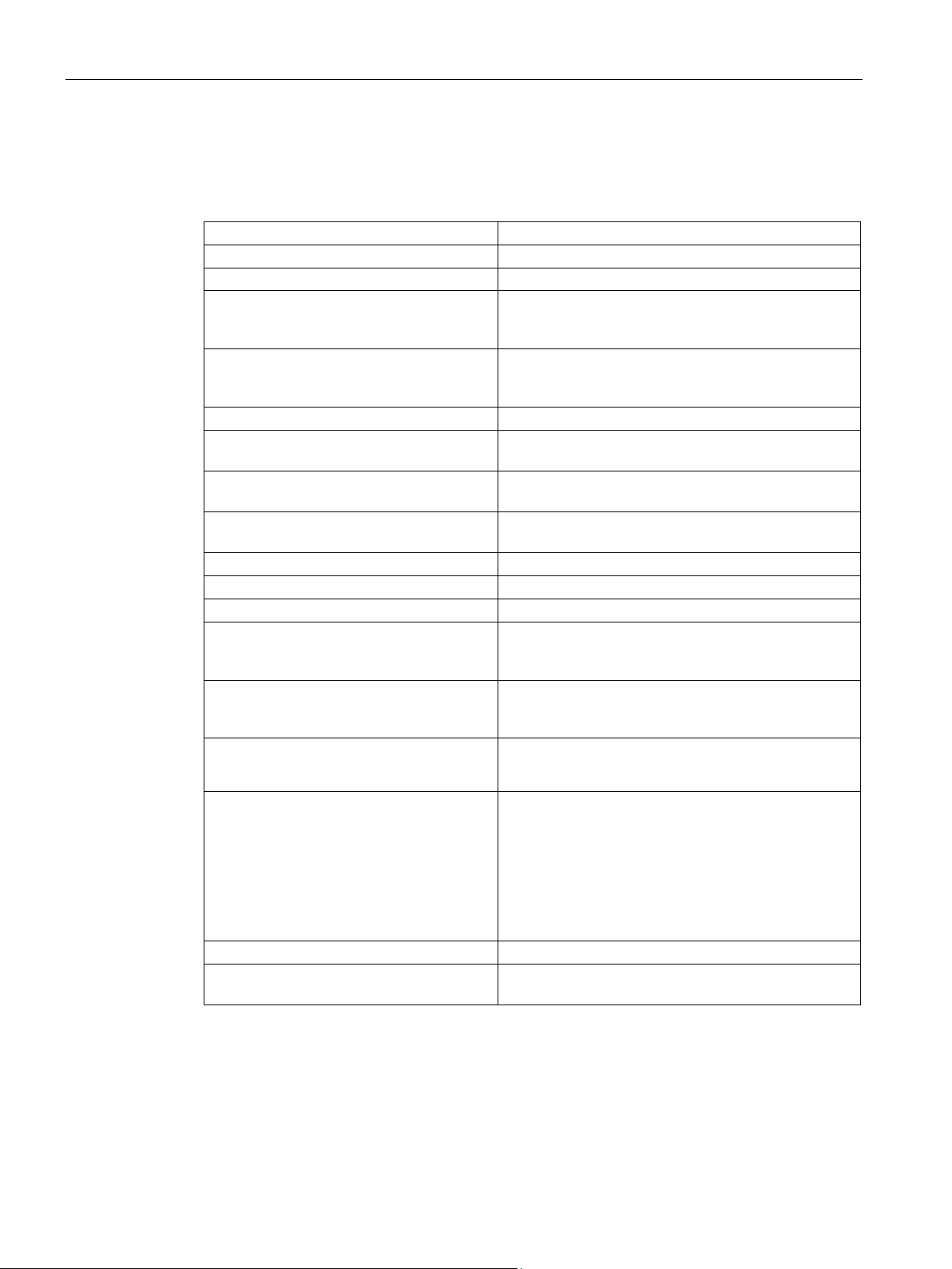
2.2.2
Technical features
Type of motor
Permanent-magnet synchronous motor
Magnet material
Rare-earth magnetic material
Cooling
Natural cooling
(IEC 60034-1)
+40 °C
(IEC 60034-18-41)
Operating range
-15° to +40° C, derating at higher temperatures
1 and IEC 60034–1)
EN 60034-7 (IEC 60034-7)
EN 60034-5 (IEC 60034-5)
Temperature monitoring
Temperature sensor in the stator winding
Paint finish
Anthracite (RAL 7016)
Shaft extension acc. to DIN 6885, Sheet 1
Shaft with feather key, form A
(IEC 60072–1)
(IEC 60034-14)
Connection
Connectors for signals and power, can be rotated
1)
2)
Can only be selected for SH36
2.2 Technical features and environmental conditions
Table 2- 1 Technical features of the motor
Insulation of the stator winding according to
EN 60034-1
Impulse voltage insulation class according
to EN 60034-18-41
Installation altitude (according to EN 60034–
Type of construction according to
Degree of protection according to
Radial eccentricity, concentricity, and axial
eccentricity according to DIN 42955
1)
Vibration severity grade according to EN
60034-14
Sound pressure level LpA (1 m) according to
DIN EN ISO 1680, max. tolerance + 3 dB(A)
Integrated encoder systems for motors with
DRIVE-CLiQ interface
Temperature class 155 °C (F) for a winding temperature of ΔT = 100 K at an ambient temperature of
IVIC: C
≤ 1000 m above sea level, otherwise power derating
IM B5 (IM V1, IM V3)
IP64
Tolerance N (normal)
Grade A is maintained up to rated speed
• 1FK703☐ to 1FK704☐: 55 dB(A)
• 1FK706☐: 65 dB(A)
• AS24DQI
• AM24DQI
• AS20DQI
• AM20DQI
2)
• R14DQ resolver
• R15DQ resolver
2)
Holding brake Optional integrated holding brake (free of backlash, 24
Radial eccentricity of the shaft extension, concentricity of centering edge, and axial excentricity of
the mounting flange to the axis of the shaft extension.
S-1FK7 DYA G2 synchronous motors with planetary gearbox
24 Operating Instructions, 05/2018, A5E44881183B AA
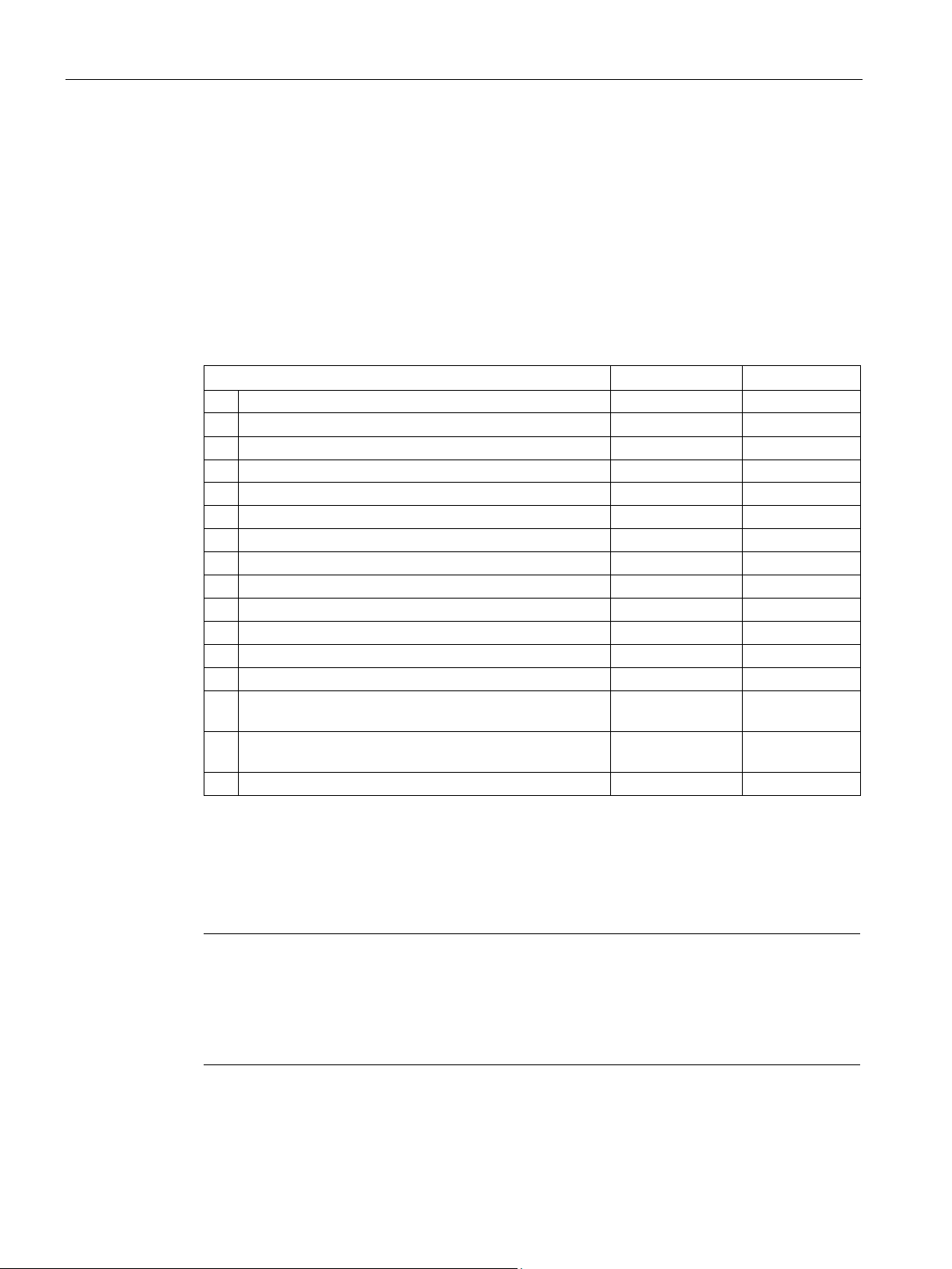
V)
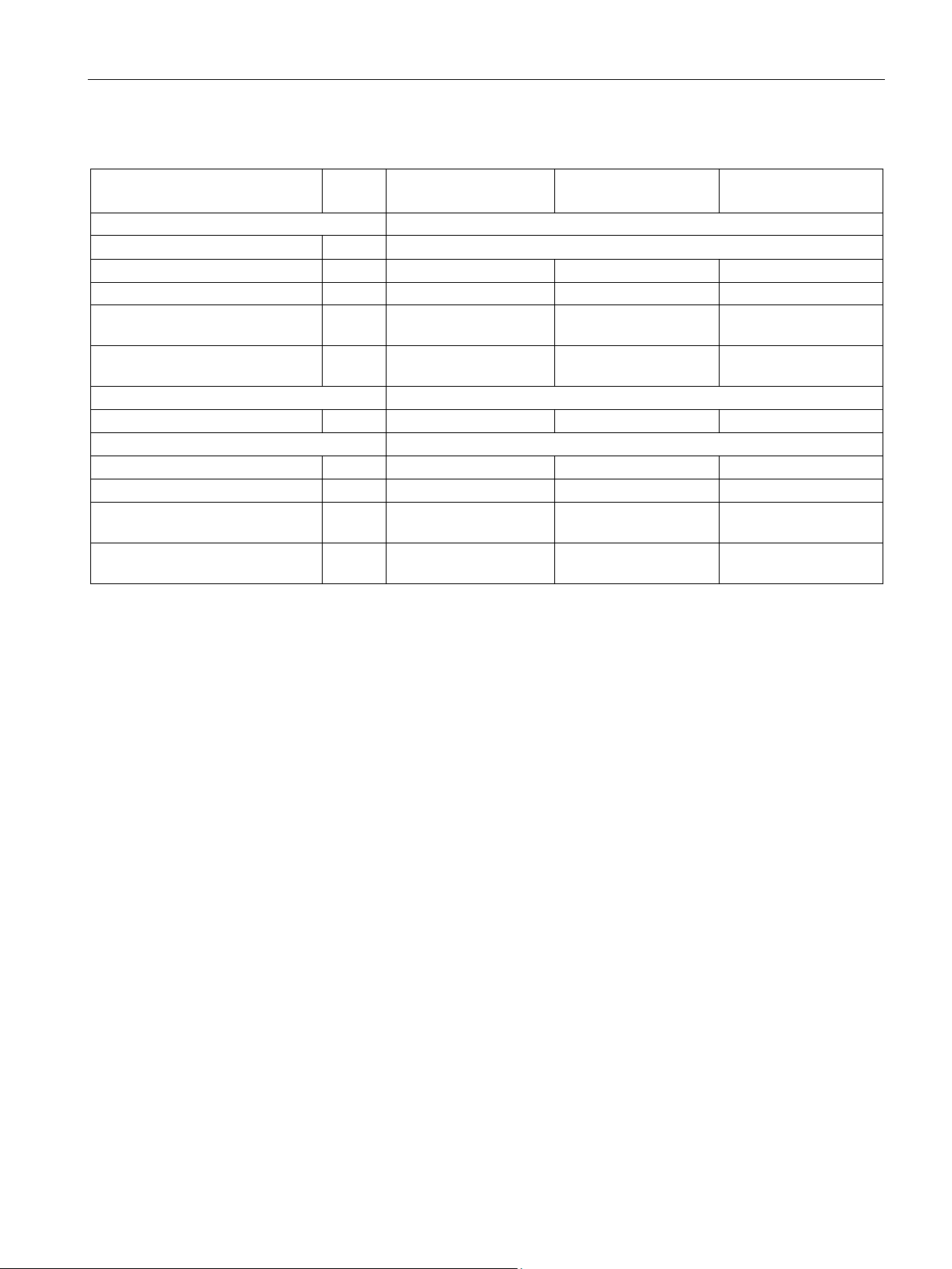
2.2 Technical features and environmental conditions
Unit
1FK7032-2AK71-1☐☐3-
Z A03
1FK7040-2AK71-
1☐☐3-Z A13
1FK7060-2AH71-
1☐☐3-Z A73
Transmission ratio i
10
Max. output torque
M2dyn
*
Nm
43.6
49.4
174.6
Max. output speed (briefly)
rpm
800
700
600
the shaft extension
F
shaft extension
F
A
Degree of protection
64
Brake holding torque
Nm
1.9
4.0
13.0
Type of output shaft
Plain shaft
Total weight without holding brake
kg
4.2
6.2
13.8
Total weight with holding brake
kg
4.5
6.8
14.5
brake
brake
* M2dyn = maximum permissible output torque of the geared motor that may be output for a short period of time
Table 2- 2 Technical data of the 1FK7 DYA G2 geared motor
Torsional backlash arcmin 8
Description of the motors
Max. permissible radial force at
R
Max. permissible axial force at the
Moment of inertia without holding
Moment of inertia with holding
N 1700 2800 5000
N 1550 1900 4000
kgcm² 0.66 1.65 7.9
kgcm² 0.76 1.97 8.9
S-1FK7 DYA G2 synchronous motors with planetary gearbox
Operating Instructions, 05/2018, A5E44881183B AA
25
Description of the motors
2.2.3
Environmental conditions
Environmental conditions are based on climate class 3K4
Influencing environmental variables
Unit
Value
a)
Low air temperature
°C
- 15
c)
Low relative humidity
%
5
d)
High relative humidity
%
95
e)
Low absolute humidity
g/m3
1
f)
High absolute humidity
g/m3
29
g)
Rate of temperature change1)
°C/min
0.5
h)
Low air pressure4)
kPa
89
i)
High air pressure2)
kPa
106
j)
Solar radiation
W/m2
700
k)
Thermal radiation
-
-
l)
Air movement3)
m/s
1.0
m)
Condensation
-
Not permissible
(rain, snow, hail, etc.)
class
p)
Formation of ice
-
-
1)
2)
3)
4)
The limit value of 89 kPa covers applications at altitudes up to 1000 m.
Note
Installation instructions
SIMOTICS S motors are not suitable for operation
•
•
2.2 Technical features and environmental conditions
You can classify the environmental conditions according to standard DIN EN 60721-3-3 for
fixed installation locations that are weather protected. The environmental effects and their
limit values are defined in various classes in this standard.
With the exception of environmental influences "Condensation", "Low air temperature" and
"Low air pressure", you can assign SIMOTICS S servomotors to climate class 3K4.
The following temperature ranges apply for natural-cooled and forced-ventilation motors.
Table 2- 3
b) High air temperature °C + 40
n) Wind-driven precipitation
o) Water (other than rain) - See protection
- -
Averaged over a period of 5 min
Conditions in mines are not considered.
A cooling system based on natural convection can be disturbed by unforeseen air movements.
In salt-laden or aggressive atmospheres
Outdoors
S-1FK7 DYA G2 synchronous motors with planetary gearbox
26 Operating Instructions, 05/2018, A5E44881183B AA

Description of the motors
2.2.4
Degree of protection
2.2.5
Noise emission
Note
External noise
Noise not generated by the gearbox but emitted from it is not taken into consideration.
Noise emitted by the drive and driven machines or the base are not t
1FK703 with
NP015
1FK704 with
NP025
1FK706 with
NP035
tions)
2.2 Technical features and environmental conditions
You find additional data on the environmental conditions, such as ambient temperatures or
conditions for transport and storage of the motors, in the relevant chapters of this
documentation.
1FK7 DYA G2 motors are available with an IP64 degree of protection.
The geared motors are certified for a wide range of installation and operating conditions.
These conditions such as rigid or vibration-isolated foundation design influence noise
emission, sometimes significantly.
The circumferential velocity of the motor pinion has a significant influence on the additional
gearbox noise. This is the reason that higher speeds or low transmission ratios result in
higher noise.
aken into consideration.
When operated in the speed range 0 to rated speed, 1FK7 DYA G2 motors can reach the
following measuring-surface sound pressure level Lp(A):
Table 2- 4 Sound pressure level
Geared motor (under no-load condi-
dB(A) ≤ 65 ≤ 65 ≤ 68
S-1FK7 DYA G2 synchronous motors with planetary gearbox
Operating Instructions, 05/2018, A5E44881183B AA
27
Description of the motors
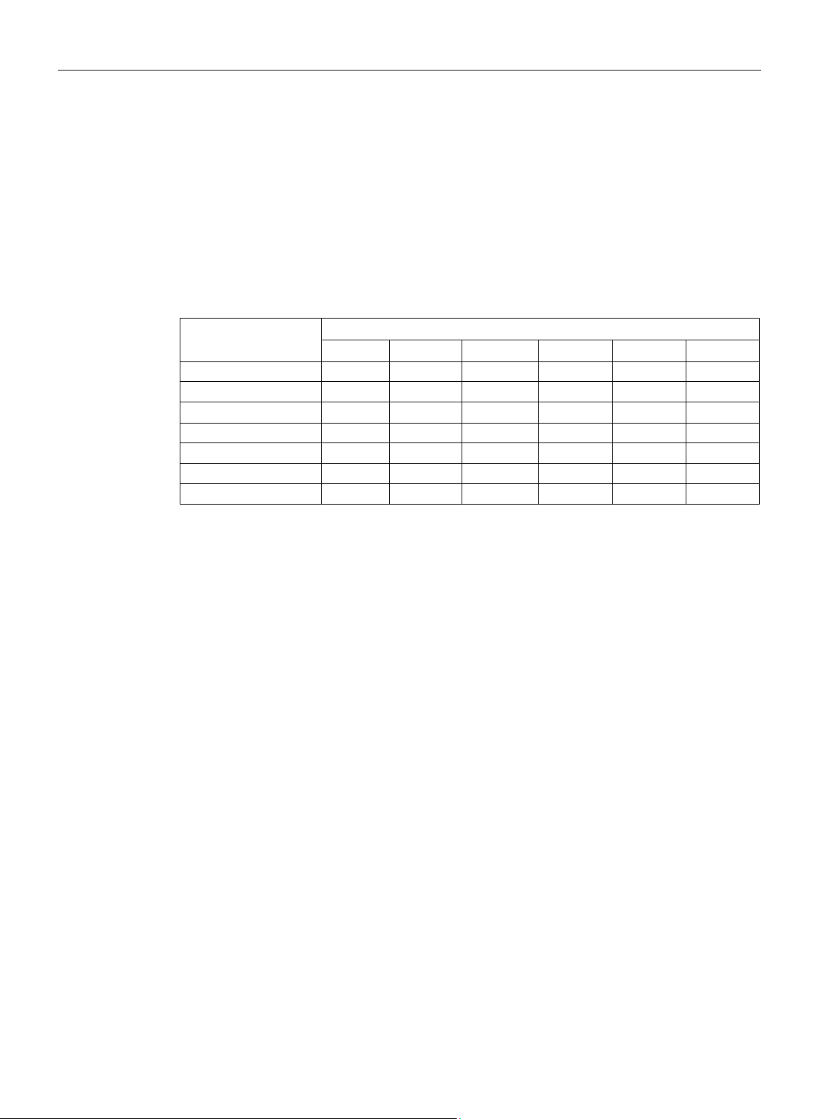
2.3
Derating factors
Installation altitude
above sea level in m
Ambient temperature in °C
30
35
40
45
50
55
1000
1.05
1.02
1.00
0.97
0.95
0.92
1500
1.02
1.00
0.97
0.95
0.92
0.89
2500
0.97
0.95
0.92
0.89
0.87
0.84
3000
0.95
0.92
0.89
0.87
0.84
0.81
3500
0.92
0.89
0.87
0.84
0.81
0.77
4000
0.89
0.87
0.84
0.81
0.77
0.74
M
×
M
/ Nm = reduced torque at rated speed
M
N
/ Nm = rated torque S1 (100K)
M
0
/ Nm = static torque (100K)
x
= derating factor
2.3 Derating factors
Under conditions other than those specified above (ambient temperature > 40° C or
installation altitude > 1000 m above sea level), the permissible torques/powers are shown in
the following table.
Ambient temperatures and installation altitudes are rounded off to 5° C or 500 m
respectively.
Table 2- 5 Power derating depending on the installation altitude and the ambient temperature (de-
rating factor x
2000 1.00 0.97 0.95 0.92 0.89 0.87
)
D
Factors xD refer to static torque M0.
The values required are provided in the M-n diagrams in the Configuration Manual for the
1FK7 G2.
Determine the reduced torque using the following formula:
=
M
- (
M
- (
red
x
N
))
D
M
0
0
red
D
You shift the S1 characteristic curve in parallel.
At installation altitudes of 2000 m above sea level or higher, the voltage stress on the motors
must be reduced accordingly based on the "Factors for reducing the maximum DC-link
voltage" table (reciprocal values from EN 60664-1 Table A. 2).
S-1FK7 DYA G2 synchronous motors with planetary gearbox
28 Operating Instructions, 05/2018, A5E44881183B AA
 Loading...