

Siemens SIMOTICS M-1PH818, SIMOTICS M-1PH828, SIMOTICS M-1PH822 Operating And Installation Instructions

www.siemens.com/drives
Operating Instructions
Installation Instructions
Main motors
SIMOTICS M-1PH8
Type 1PH818., 1PH822., 1PH828.
Edition 10/2017

20.10.2017 15:09
V20.00

Main motors
SIMOTICS M-1PH8
Type 1PH818., 1PH822., 1PH828.
Introduction
1
Operating Instructions
Installation Instructions
Safety information
Description
Preparations for use
Mounting
Electrical connection
Commissioning
Operation
2
3
4
5
6
7
8
Maintenance
Spare parts
Disposal
Service and Support
Technical specifications
Quality documents
Additional documents
9
10
11
A
B
C
D
Edition 10/2017

Legal information
Warning notice system
This manual contains notices you have to observe in order to ensure your personal safety, as well as to prevent
damage to property. The notices referring to your personal safety are highlighted in the manual by a safety alert
symbol, notices referring only to property damage have no safety alert symbol. These notices shown below are
graded according to the degree of danger.
DANGER
indicates that death or severe personal injury will result if proper precautions are not taken.
WARNING
indicates that death or severe personal injury may result if proper precautions are not taken.
CAUTION
indicates that minor personal injury can result if proper precautions are not taken.
NOTICE
indicates that property damage can result if proper precautions are not taken.
If more than one degree of danger is present, the warning notice representing the highest degree of danger will be
used. A notice warning of injury to persons with a safety alert symbol may also include a warning relating to property
damage.
Qualified Personnel
The product/system described in this documentation may be operated only by personnel qualified for the specific
task in accordance with the relevant documentation, in particular its warning notices and safety instructions. Qualified
personnel are those who, based on their training and experience, are capable of identifying risks and avoiding
potential hazards when working with these products/systems.
Proper use of Siemens products
Note the following:
WARNING
Siemens products may only be used for the applications described in the catalog and in the relevant technical
documentation. If products and components from other manufacturers are used, these must be recommended or
approved by Siemens. Proper transport, storage, installation, assembly, commissioning, operation and
maintenance are required to ensure that the products operate safely and without any problems. The permissible
ambient conditions must be complied with. The information in the relevant documentation must be observed.
Trademarks
All names identified by ® are registered trademarks of Siemens AG. The remaining trademarks in this publication
may be trademarks whose use by third parties for their own purposes could violate the rights of the owner.
Disclaimer of Liability
We have reviewed the contents of this publication to ensure consistency with the hardware and software described.
Since variance cannot be precluded entirely, we cannot guarantee full consistency. However, the information in
this publication is reviewed regularly and any necessary corrections are included in subsequent editions.
Siemens AG
Process Industries and Drives
Postfach 48 48
90026 NÜRNBERG
GERMANY
Document order number: A5E35768675A AC
Ⓟ 10/2017 Subject to change
Copyright © Siemens AG 2017.
All rights reserved

Table of contents
1 Introduction.................................................................................................................................................13
2 Safety information.......................................................................................................................................15
2.1 Information for the nominated person in control of the electrical installation.........................15
2.2 The five safety rules...............................................................................................................15
2.3 Qualified personnel................................................................................................................16
2.4 Safe handling.........................................................................................................................16
2.5 Electrostatic sensitive devices...............................................................................................18
2.6 Interference immunity.............................................................................................................19
2.7 Interference voltages when operating the converter..............................................................19
2.8 Electromagnetic fields when operating electrical power engineering installations.................20
3 Description..................................................................................................................................................21
4 Preparations for use...................................................................................................................................29
4.1 Safety-related aspects to consider when configuring the plant..............................................29
4.2 Observing the operating mode...............................................................................................29
4.3 Cooling water quality for water-cooled motors.......................................................................29
4.4 Ensuring cooling.....................................................................................................................30
4.5 Interlock circuit for the external fan........................................................................................33
4.6 Interlock circuit for anti-condensation heating (option)...........................................................33
4.7 Thermal motor protection.......................................................................................................34
4.8 Overheating during periodic duty...........................................................................................34
4.9 Noise emissions.....................................................................................................................34
4.10 Rotational speed limit values.................................................................................................35
4.11 System-inherent frequencies.................................................................................................35
4.12 Torsional loading of the drive train due to faults in the electrical supply................................35
4.13 Transport and storage............................................................................................................36
4.13.1 Checking the delivery.............................................................................................................36
4.13.2 Lifting and transportation........................................................................................................36
4.13.3 Transporting a force-ventilated motor that has already been in operation.............................40
4.13.4 Transporting a water-cooled motor that has already been in operation.................................40
4.13.5 Transporting the machine set.................................................................................................41
4.13.6 Storage...................................................................................................................................41
4.13.7 Attaching the rotor shipping brace prior to storage................................................................43
4.13.8 Protect the cooling water system of water-cooled motors......................................................44
4.13.9 Protection against corrosion...................................................................................................45
SIMOTICS M-1PH8 1PH818., 1PH822., 1PH828.
Operating Instructions 10/2017 5

Table of contents
4.14 Converter operation...............................................................................................................45
4.14.1 Connecting to a converter......................................................................................................45
4.14.2 Insulated bearings for converter operation.............................................................................46
5 Mounting.....................................................................................................................................................49
5.1 Preparing for installation........................................................................................................49
5.1.1 Requirements for installation..................................................................................................49
5.1.2 Insulation resistance and polarization index..........................................................................50
5.1.3 Testing the insulation resistance and polarization index........................................................50
5.1.4 Prepare the mounting surfaces (IM B3).................................................................................53
5.1.5 Prepare the mounting surfaces (flange mounting).................................................................53
5.2 Lift the machine to where it will be mounted and position it...................................................53
5.2.1 Preconditions for correct alignment and secure attachment .................................................53
5.2.2 Checking the load handling attachments...............................................................................53
5.2.3 Removing anti-corrosion protection.......................................................................................54
5.2.4 Mounting the output elements................................................................................................54
5.2.5 Lifting and transporting the machine......................................................................................56
5.2.6 Open the condensation water drain holes (water-cooled motor)...........................................57
5.2.7 Open condensation drain holes (air-cooled motor, L12)........................................................58
5.2.8 Putting the machine down......................................................................................................59
5.2.9 Roughly aligning the machine................................................................................................59
5.3 Installing the machine............................................................................................................60
5.3.1 Selecting fixing screws...........................................................................................................60
5.3.2 Preconditions for smooth, vibration-free operation................................................................61
5.3.3 Vibration severity....................................................................................................................61
5.3.4 Aligning to the driven machine...............................................................................................62
5.3.5 Mounting the motor................................................................................................................64
5.4 Connecting the cooling water supply.....................................................................................64
5.5 Refitting the external fan........................................................................................................65
6 Electrical connection...................................................................................................................................67
6.1 Preparation.............................................................................................................................68
6.1.1 Selecting cables.....................................................................................................................68
6.1.2 Connect up the ground conductor..........................................................................................68
6.2 Connecting.............................................................................................................................69
6.2.1 Circuit diagram.......................................................................................................................69
6.2.2 Terminal designation..............................................................................................................69
6.2.3 Laying cables.........................................................................................................................70
6.2.4 Electrical connection data......................................................................................................70
6.2.5 Connection with cable lugs....................................................................................................71
6.2.6 Connecting aluminum conductors..........................................................................................73
6.2.7 Stepless mating face for the seal in the terminal box cover...................................................73
6.2.8 Performing connection operations.........................................................................................74
6.2.9 Internal equipotential bonding................................................................................................74
6.3 Auxiliary circuits.....................................................................................................................75
6.3.1 Selecting cables.....................................................................................................................75
6.3.2 Connecting an external fan....................................................................................................75
6.3.2.1 Connecting an EC external fan..............................................................................................77
6.3.2.2 Connecting an external fan with three-phase motor (option L75)..........................................78
SIMOTICS M-1PH8 1PH818., 1PH822., 1PH828.
6 Operating Instructions 10/2017

Table of contents
6.3.2.3 Supply values for external fans with three-phase motor (option L75)....................................79
6.3.2.4 Attached air discharge throttle plate (option L75)..................................................................80
6.3.3 Connecting the speed encoder..............................................................................................82
6.3.4 Connect the holding brake.....................................................................................................83
6.3.5 Connecting the temperature sensor.......................................................................................83
6.3.6 Connecting to a converter......................................................................................................84
6.3.7 Converter operation on a grounded network..........................................................................85
7 Commissioning...........................................................................................................................................87
7.1 Insulation resistance and polarization index..........................................................................88
7.2 Checks to be carried out prior to commissioning ..................................................................89
7.3 Perform a test run with the water-cooled motor.....................................................................91
7.4 Switching on...........................................................................................................................91
7.5 Test run..................................................................................................................................92
7.6 Set values for monitoring the bearing temperature (optional)................................................93
8 Operation....................................................................................................................................................95
8.1 Safety guidelines in operation................................................................................................95
8.2 Do not operate water-cooled motors without cooling water...................................................97
8.3 Switching on the machine......................................................................................................97
8.4 Switching off water-cooled motors.........................................................................................98
8.5 Switching off force-ventilated motors.....................................................................................98
8.6 Switching on again after an emergency switching-off............................................................98
8.7 Stoppages..............................................................................................................................98
8.7.1 Avoidance of damage to roller bearings during stoppages....................................................99
8.8 Decommissioning the machine..............................................................................................99
8.9 Re-commissioning the machine...........................................................................................100
8.10 Faults...................................................................................................................................100
8.10.1 Inspections in the event of faults..........................................................................................100
8.10.2 Electrical faults at force-ventilated motors...........................................................................100
8.10.3 Electrical faults at water-cooled motors...............................................................................101
8.10.4 Mechanical faults.................................................................................................................102
8.10.5 Roller bearing faults.............................................................................................................103
8.10.6 Holding brake faults.............................................................................................................103
9 Maintenance.............................................................................................................................................105
9.1 Observe the operating instructions of the components........................................................105
9.2 Inspection and maintenance................................................................................................106
9.2.1 Inspections in the event of faults..........................................................................................107
9.2.2 Initial inspection....................................................................................................................107
9.2.3 Main inspection....................................................................................................................108
9.2.4 Regreasing intervals............................................................................................................109
9.2.5 Changing bearings when using permanently lubricated rolling-contact bearings................109
9.2.6 Maintenance.........................................................................................................................109
9.2.6.1 Measuring the insulation resistance during the course of maintenance work......................109
SIMOTICS M-1PH8 1PH818., 1PH822., 1PH828.
Operating Instructions 10/2017 7

Table of contents
9.2.6.2 Maintenance intervals..........................................................................................................110
9.2.6.3 Rolling-contact bearings.......................................................................................................110
9.2.6.4 Lubrication............................................................................................................................110
9.2.6.5 Cleaning the spent grease chamber....................................................................................116
9.2.6.6 Maintaining the cooling water system..................................................................................116
9.2.6.7 Servicing the external fan.....................................................................................................117
9.2.6.8 Maintaining terminal boxes..................................................................................................118
9.3 Repair...................................................................................................................................119
9.3.1 Prepare servicing work.........................................................................................................119
9.3.2 Screws with preCOTE coating.............................................................................................120
9.3.3 Disassembling a water-cooled motor...................................................................................120
9.3.4 Dissembling a force-ventilated motor...................................................................................121
9.3.5 Removing and installing the protecting ring.........................................................................122
9.3.6 Removing and mounting the bearing shields.......................................................................123
9.3.7 Installing and sealing the motor...........................................................................................123
9.3.8 Sealing the motor (type 1PH828.)........................................................................................125
9.3.9 Relocating the external fan (type 1PH828.).........................................................................126
9.3.10 Removing and mounting the external fan............................................................................126
9.3.11 Removing and mounting the speed sensor..........................................................................128
9.3.12 Connecting the speed encoder............................................................................................130
9.3.13 Replacing the DRIVE-CLiQ interface (encoder module)......................................................130
9.3.14 Touch up any damaged paintwork.......................................................................................131
10 Spare parts...............................................................................................................................................133
10.1 Ordering data.......................................................................................................................133
10.2 Spare parts kits....................................................................................................................133
10.3 Holding brake.......................................................................................................................134
10.4 Ordering spare parts via the Internet...................................................................................134
10.5 Anti-condensation heating....................................................................................................134
10.6 Water-cooled motor..............................................................................................................135
10.6.1 Water-cooled motor, complete.............................................................................................135
10.6.2 Roller bearing cartridge DE with radial shaft sealing ring with regreasing...........................136
10.6.3 Rolling-contact bearing bush drive end, belt coupling..........................................................137
10.6.4 Rolling-contact bearing bush drive end, coupling output, with regreasing...........................138
10.6.5 Rolling-contact bearing bush drive end, coupling output, with permanent lubrication.........139
10.6.6 Rolling-contact bearing bush non-drive end, with permanent lubrication.............................140
10.6.7 Roller bearing cartridge NDE, with regreasing (type 1PH818., 1PH822.)............................141
10.6.8 Roller bearing cartridge NDE, with regreasing (type 1PH828.)............................................142
10.6.9 Rolling-contact bearing bush non-drive end "Performance"................................................143
10.7 Force-ventilated motor.........................................................................................................144
10.7.1 Force-ventilated motor, complete.........................................................................................144
10.7.2 External fan..........................................................................................................................145
10.7.3 External fan (option L75)......................................................................................................145
10.7.4 Roller bearing cartridge DE with radial shaft sealing ring with regreasing...........................146
10.7.5 Roller bearing cartridge DE, belt coupling............................................................................147
10.7.6 Roller bearing cartridge DE, coupling output, with regreasing.............................................148
10.7.7 Roller bearing cartridge DE, coupling output, with permanent lubrication...........................149
10.7.8 Roller bearing cartridge NDE, with permanent lubrication...................................................150
10.7.9 Roller bearing cartridge NDE, with regreasing (type 1PH818., 1PH822.)............................151
SIMOTICS M-1PH8 1PH818., 1PH822., 1PH828.
8 Operating Instructions 10/2017

Table of contents
10.7.10 Roller bearing cartridge NDE, with regreasing (type 1PH828.)............................................152
10.7.11 Roller bearing cartridge NDE, "Performance"......................................................................153
10.8 Terminal box........................................................................................................................154
10.9 Speed encoder (type 1PH818., 1PH822.)............................................................................155
10.10 Speed encoder (type 1PH828.)............................................................................................156
11 Disposal....................................................................................................................................................157
11.1 RoHS - restricting the use of certain hazardous substances...............................................157
11.2 Preparing for disassembly....................................................................................................157
11.3 Dismantling the machine......................................................................................................158
11.4 Disposal of components.......................................................................................................158
A Service and Support.................................................................................................................................161
B Technical specifications............................................................................................................................163
B.1 Tightening torques for screw and bolt connections..............................................................163
C Quality documents....................................................................................................................................165
D Additional documents...............................................................................................................................167
D.1 Reader notes on the operating instructions of the holding brake.........................................167
D.2 Operating instructions, holding brake...................................................................................169
D.3 Operating instructions for the single-phase EC external fan, suction, SH180.....................193
D.4 Operating instructions for the single-phase EC external fan, suction, SH225.....................207
D.5 Operating instructions for the single-phase EC external fan, pressing, SH180...................221
D.6 Operating instructions for the single-phase EC external fan, pressing, SH225...................235
D.7 Operating instructions for the three-phase EC external fan, suction, SK180.......................249
D.8 Operating instructions for the three-phase EC external fan, suction, SK225.......................263
D.9 Operating instructions for the three-phase EC external fan, pressing, SH180....................279
D.10 Operating instructions for the three-phase EC external fan, pressing, SH225....................293
Index.........................................................................................................................................................309
Tables
Table 3-1 Elements on the rating plate........................................................................................................22
Table 3-2 Machine design ........................................................................................................................23
Table 3-3 Technical data of the holding brake............................................................................................26
Table 3-4 Roller bearing versions .............................................................................................................27
Table 4-1 Cooling water specification .......................................................................................................29
Table 4-2 Pressure drop in motors with pipe connection .........................................................................33
Table 4-3 Tightening torque and preloading force for axially fixing the rotor..............................................39
Table 5-1 Stator winding insulation resistance at 40° C..............................................................................51
SIMOTICS M-1PH8 1PH818., 1PH822., 1PH828.
Operating Instructions 10/2017 9

Table of contents
Table 5-2 Maximum permitted radial vibration severity...............................................................................61
Table 5-3 Maximum permitted axial vibration severity................................................................................61
Table 5-4 Permissible deviations when aligning the motor.........................................................................63
Table 5-5 Rate of flow and pressure drop...................................................................................................65
Table 6-1 Terminal designations using the 1U1-1 as an example..............................................................69
Table 6-2 Data for electrical connection......................................................................................................71
Table 7-1 Minimum radial forces.................................................................................................................90
Table 7-2 Set values for monitoring the bearing temperatures before commissioning...............................93
Table 7-3 Set values for monitoring the bearing temperatures...................................................................93
Table 8-1 Electrical faults .......................................................................................................................101
Table 8-2 Electrical faults .......................................................................................................................101
Table 8-3 Mechanical faults.......................................................................................................................102
Table 8-4 Roller bearing faults .............................................................................................................103
Table 9-1 Checks after installation or repair .............................................................................................107
Table 9-2 Checks that must be performed during the main inspection.....................................................108
Table 9-3 Maintenance measures.............................................................................................................110
Table 9-4 Criteria for selecting roller bearing greases...............................................................................111
Table 9-5 Roller bearing greases for vertical and horizontal types of construction ..................................112
Table 9-6 Alternative greases with NLGI Class 2 for motors with a horizontal type of construction.........112
Table 9-7 Grease for the "Performance" version.......................................................................................113
Table 10-1 Motor, complete ........................................................................................................................135
Table 10-2 Spare parts for rolling-contact bearing bush drive end with mounted gearing, with
regreasing ................................................................................................................................136
Table 10-3 Spare parts for rolling-contact bearing bush drive end with belt coupling, with regreasing......137
Table 10-4 Spare parts for rolling-contact bearing bush drive end, with coupling output, with regreasing ....138
Table 10-5 Spare parts for rolling-contact bearing bush drive end, with coupling output, with permanent
lubrication .................................................................................................................................139
Table 10-6 Spare parts for rolling-contact bearing bush non-drive end, permanent lubrication .................140
Table 10-7 Spare part, roller bearing cartridge NDE, with regreasing (type 1PH818., 1PH822.) ..............141
Table 10-8 Spare part, roller bearing cartridge NDE, with regreasing (type 1PH828.)...............................142
Table 10-9 Spare parts for rolling-contact bearing bush non-drive end with regreasing.............................143
Table 10-10 Motor, complete .......................................................................................................................144
Table 10-11 Spare parts for external fan.......................................................................................................145
Table 10-12 Spare parts for rolling-contact bearing bush drive end with mounted gearing, with
regreasing ................................................................................................................................146
Table 10-13 Spare parts for rolling-contact bearing bush drive end with belt coupling, with regreasing......147
Table 10-14 Spare parts for rolling-contact bearing bush drive end, with coupling output, with regreasing ....148
Table 10-15 Spare parts for rolling-contact bearing bush drive end, with coupling output, with permanent
lubrication .................................................................................................................................149
Table 10-16 Spare parts for roller bearing cartridge, non-drive end, permanent lubrication ........................150
Table 10-17 Spare part, roller bearing cartridge NDE, with regreasing (type 1PH818., 1PH822.) ..............151
SIMOTICS M-1PH8 1PH818., 1PH822., 1PH828.
10 Operating Instructions 10/2017

Table of contents
Table 10-18 Spare part, roller bearing cartridge NDE, with regreasing (type 1PH828.) ..............................152
Table 10-19 Spare parts for rolling-contact bearing bush non-drive end with regreasing.............................153
Table 10-20 Spare parts for terminal box .....................................................................................................154
Table 10-21 Spare part, speed encoder (type 1PH818., 1PH822.) ..............................................................155
Table 10-22 Spare part, speed encoder (type 1PH828.) ............................................................................156
Table B-1 Tightening torques for screw/bolt connections with a tolerance of ±10%.................................163
Table D-1 Technical data of the holding brake..........................................................................................167
Figures
Figure 3-1 Schematic layout of rating plate..................................................................................................21
Figure 4-1 Air guidance from the DE to the NDE (schematic representation, types 1PH818. and
1PH822.).....................................................................................................................................31
Figure 4-2 Bypass for 1PH822. for IP23 ......................................................................................................32
Figure 4-3 Air guidance from the NDE to the DE (schematic representation, type 1PH828.) for IP55........32
Figure 4-4 Lifting the machine (schematic representation)...........................................................................38
Figure 4-5 Rotor shipping brace...................................................................................................................39
Figure 4-6 Schematic representation of a single drive.................................................................................46
Figure 5-1 Balancing type on the drive-end side..........................................................................................54
Figure 5-2 Water drain holes........................................................................................................................58
Figure 5-3 Water drain holes, for types 1PH818., 1PH822..........................................................................58
Figure 5-4 Max. permissible vibration velocity, taking into account the vibration displacement and
vibration acceleration..................................................................................................................62
Figure 5-5 Aligning the motor.......................................................................................................................63
Figure 6-1 Terminal lug ① for the grounding conductor for a force-ventilated motor..................................68
Figure 6-2 Terminal lug ① for the grounding conductor for a water-cooled motor......................................69
Figure 6-3 External fan terminal box ① (schematic representation)............................................................77
Figure 6-4 External fan terminal box ① (schematic representation)............................................................78
Figure 6-5 Throttle plate for suction-type ventilation (DE to NDE)................................................................81
Figure 6-6 Throttle plate for forced-draft ventilation (NDE to DE).................................................................81
Figure 6-7 Detailed view: Plug-in connection ..............................................................................................82
Figure 6-8 Sensor Module ① mounted on the terminal box........................................................................83
Figure 9-1 Flat grease nipples ① and ②, schematic representation for types 1PH818. and 1PH822. ....115
Figure 9-2 Flat grease nipple ① and ② (schematic representation for type 1PH828.)............................116
Figure 9-3 Fitting the protecting ring...........................................................................................................123
Figure 9-4 Sealing gap between the enclosure and bearing shields (schematic representation)..............125
Figure 9-5 Installing the rotary shaft seal....................................................................................................126
Figure 9-6 Unscrewing the external fan (1PH818., 1PH822.)....................................................................127
Figure 9-7 Unscrewing the external fan (1PH828.)....................................................................................127
Figure 9-8 Detailed view of the speed encoder..........................................................................................128
SIMOTICS M-1PH8 1PH818., 1PH822., 1PH828.
Operating Instructions 10/2017 11

Table of contents
Figure 9-9 Electrical connection of the speed sensor ................................................................................130
Figure 10-1 Schematic diagram of motor (complete)...................................................................................135
Figure 10-2 Rolling-contact bearing bush drive end with mounted gearing, with regreasing.......................136
Figure 10-3 Rolling-contact bearing bush drive end with belt coupling, with regreasing..............................137
Figure 10-4 Rolling-contact bearing bush drive end, with coupling output, with regreasing.........................138
Figure 10-5 Rolling-contact bearing bush drive end, with coupling output, with permanent lubrication.......139
Figure 10-6 Rolling-contact bearing bush non-drive end, permanent lubrication ........................................140
Figure 10-7 Roller bearing cartridge NDE, with regreasing (type 1PH818., 1PH822.).................................141
Figure 10-8 Roller bearing cartridge NDE, with regreasing (type 1PH828.).................................................142
Figure 10-9 Rolling-contact bearing bush non-drive end with regreasing ...................................................143
Figure 10-10 Schematic representation of the motor, complete.....................................................................144
Figure 10-11 Spare parts for external fan (type 1PH818., 1PH822.) ............................................................145
Figure 10-12 Rolling-contact bearing bush drive end with mounted gearing, with regreasing.......................146
Figure 10-13 Rolling-contact bearing bush drive end with belt coupling, with regreasing..............................147
Figure 10-14 Rolling-contact bearing bush drive end, with coupling output, with regreasing.........................148
Figure 10-15 Rolling-contact bearing bush drive end, with coupling output, with permanent lubrication.......149
Figure 10-16 Roller bearing cartridge, non-drive end, permanent lubrication ...............................................150
Figure 10-17 Roller bearing cartridge NDE, with regreasing (type 1PH818., 1PH822.).................................151
Figure 10-18 Roller bearing cartridge NDE, with regreasing (type 1PH828.).................................................152
Figure 10-19 Rolling-contact bearing bush non-drive end with regreasing ...................................................153
Figure 10-20 Terminal box..............................................................................................................................154
Figure 10-21 Speed encoder..........................................................................................................................155
Figure 10-22 Speed encoder (type 1PH828.).................................................................................................156
SIMOTICS M-1PH8 1PH818., 1PH822., 1PH828.
12 Operating Instructions 10/2017

Introduction
These operating instructions are valid for 1PH8 induction motors in shaft heights 180 ... 280
in a force-ventilated or water-cooled version.
● 1PH818.1 and 1PH818.3
● 1PH822.1 and 1PH822.3
● 1PH828.1
The serial number of the motor can be found on the rating plate.
These instructions describe the machine and explain how to handle it, from initial delivery to
final disposal of the equipment. Keep these instructions for later use.
Read these operating instructions before you handle the machine and follow the instructions
to become familiar with its design and operating principles and thus ensure safe, problem-free
machine operation and long service life.
Please contact the Service Center (Page 161) if you have any suggestions on how to improve
this document.
Text format features
1
The warning notice system is explained on the rear of the inside front. Always follow the safety
instructions and notices in these instructions.
In addition to the safety-related warning notices which you must read, you will find the text in
these instructions is formatted in the following way:
1. Handling instructions are always formatted as a numbered list. Always perform the steps
in the order given.
● Lists are formatted as bulleted lists.
– Lists on the second level are hyphenated.
Note
A Note is an important item of information about the product, handling of the product or the
relevant section of the document. Notes provide you with help or further suggestions/ideas.
SIMOTICS M-1PH8 1PH818., 1PH822., 1PH828.
Operating Instructions 10/2017 13

Introduction
SIMOTICS M-1PH8 1PH818., 1PH822., 1PH828.
14 Operating Instructions 10/2017

Safety information
2.1 Information for the nominated person in control of the electrical installation
This electric machine has been designed and built in accordance with the specifications
contained in Directive 2014/35/EU ("Low-Voltage Directive") and is intended for use in
industrial plants. Please observe the country-specific regulations when using the electric
machine outside the European Community. Follow the local and industry-specific safety and
setup regulations.
The persons responsible for the plant must ensure the following:
● Planning and configuration work and all work carried out on and with the machine is only
to be done by qualified personnel.
● The operating instructions must always be available for all work.
● The technical data as well as the specifications relating to the permissible installation,
connection, ambient and operating conditions are taken into account at all times.
● The specific setup and safety regulations as well as regulations on the use of personal
protective equipment are observed.
Note
2
Use the services and support provided by the appropriate Service Center (Page 161) for
planning, installation, commissioning, and servicing work.
You will find safety instructions in the individual sections of this document. Follow the safety
instructions for your own safety, to protect other people and to avoid damage to property.
Observe the following safety instructions for all activities on and with the machine.
2.2 The five safety rules
For your own personal safety and to prevent material damage when carrying out any work,
always observe the safety-relevant instructions and the following five safety rules according
to EN 50110‑1 "Working in a voltage-free state". Apply the five safety rules in the sequence
stated before starting work.
Five safety rules
1. Disconnect the system.
Also disconnect the auxiliary circuits, for example, anti-condensation heating.
2. Secure against reconnection.
3. Verify absence of operating voltage.
SIMOTICS M-1PH8 1PH818., 1PH822., 1PH828.
Operating Instructions 10/2017 15

Safety information
2.3 Qualified personnel
4. Ground and short-circuit.
5. Provide protection against adjacent live parts.
To energize the system, apply the measures in reverse order.
2.3 Qualified personnel
All work at the machine must be carried out by qualified personnel only. For the purpose of
this documentation, qualified personnel is taken to mean people who fulfill the following
requirements:
● Through appropriate training and experience, they are able to recognize and avoid risks
and potential dangers in their particular field of activity.
● They have been instructed to carry out work on the machine by the appropriate person
responsible.
2.4 Safe handling
Workplace safety depends on the attentiveness, care, and common sense of the personnel
who install, operate, and maintain the machine. In addition to the safety measures cited, as a
matter of principle, the use of caution is necessary when you are near the machine. Always
pay attention to your safety.
Also observe the following to prevent accidents:
● General safety regulations applicable in the country where the machine is deployed.
● Manufacturer-specific and application-specific regulations
● Special agreements made with the operator
● Separate safety instructions supplied with the machine
● Safety symbols and instructions on the machine and its packaging
WARNING
Live parts
Electric machines contain live parts.
Fatal or severe injuries and substantial material damage can occur if the covers are removed
or if the machine is not handled, operated, or maintained properly.
● Always observe the “five safety rules" (Page 15) when carrying out any work on the
machine.
● Only remove the covers using the methods described by these operating instructions.
● Operate the machine properly.
● Regularly and correctly maintain the machine.
SIMOTICS M-1PH8 1PH818., 1PH822., 1PH828.
16 Operating Instructions 10/2017

Safety information
2.4 Safe handling
WARNING
Rotating parts
Electric machines contain dangerous rotating parts.
Fatal or severe injuries and substantial material damage can occur if the covers are removed
or if the machine is not handled, operated, or maintained properly.
● Only remove the covers using the methods described by these operating instructions.
● Operate the machine properly.
● Regularly and correctly maintain the machine.
● Secure free-standing shaft ends and other rotating parts such as couplings, belt pulleys
etc. against touch.
WARNING
Hot surfaces
Electric machines have hot surfaces. Do not touch these surfaces. They could cause burns.
● Allow the machine to cool before starting work on the machine.
● Only remove the covers using the methods described by these operating instructions.
● Operate the machine properly.
CAUTION
Hazardous substances
Chemical substances required for the setup, operation and maintenance of machines can
present a health risk.
Poisoning, skin damage, cauterization of the respiratory tract, and other health damage may
result.
● Read the information in these operating instructions and the product information supplied
by the manufacturer.
● Observe the relevant safety regulations and wear the personal protective equipment
specified.
CAUTION
Flammable substances
Chemical substances required for the setup, operation and maintenance of machines may
be flammable.
Burns and other damage to health and material may result.
● Read the information in these operating instructions and the product information supplied
by the manufacturer.
● Observe the relevant safety regulations and wear the personal protective equipment
specified.
SIMOTICS M-1PH8 1PH818., 1PH822., 1PH828.
Operating Instructions 10/2017 17

Safety information
2.5 Electrostatic sensitive devices
WARNING
Noise emissions
During operation, the machine's noise emission levels can exceed those permitted at the
workplace, which can cause hearing damage.
Take steps to reduce noise, such as introducing covers and protective insulation or adopting
hearing protection measures, so that the machine can be operated safely within your system.
2.5 Electrostatic sensitive devices
Material damage due to electrostatic discharge
Electronic modules contain components that can be destroyed by electrostatic discharge.
These components can be damaged or destroyed if they are not handled correctly. To protect
equipment against damage, follow the instructions given below.
● Only touch electronic modules if you absolutely have to work on them.
● The body of the person concerned must have been electrostatically discharged and
grounded immediately before any electronic modules are touched.
● Electronic modules should not be brought into contact with electrically insulating materials,
such as:
– Plastic film
– Plastic parts
– Insulating table supports
– Clothing made of synthetic fibers
● Always place electrostatic sensitive devices on conductive bases.
● Always pack, store and transport electronic modules or components in conductive
packaging, such as:
– Metallized plastic or metal containers
– Conductive foam material
– Domestic aluminum foil
SIMOTICS M-1PH8 1PH818., 1PH822., 1PH828.
18 Operating Instructions 10/2017
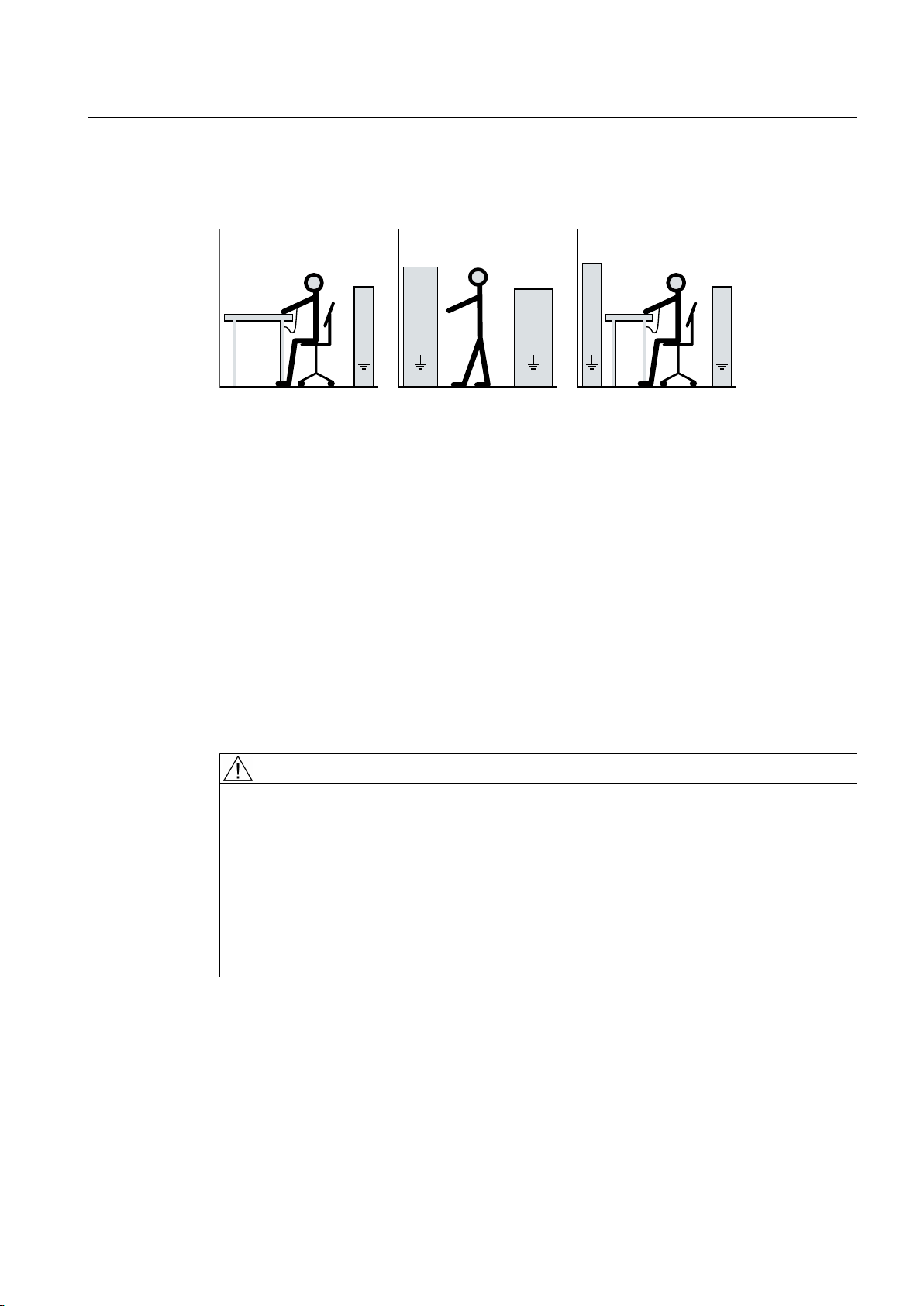
6HDWLQJSRVLWLRQ
6WDQGLQJSRVLWLRQ
6WDQGLQJVHDWLQJSRVLWLRQ
EE
D
F
D
IIIII
D
FF
H
GG
H
G
See also
Safety information
2.6 Interference immunity
The necessary ESD protective measures for electrostatic sensitive devices are illustrated once
again in the following drawings:
a = conductive floor surfaceb = ESD table c = ESD shoes
d = ESD overall e = ESD wristband f = cabinet ground connection
Replacing the DRIVE-CLiQ interface (encoder module) (Page 130)
2.6 Interference immunity
By selecting suitable signal cables and evaluation units, companies operating complete plants
and systems must ensure that the interference immunity of the machine is not diminished.
2.7 Interference voltages when operating the converter
WARNING
Interference voltages when operating the converter
When a converter is in operation, the emitted interference varies in strength depending on
the converter (manufacturer, type, interference suppression measures undertaken). On
machines with integrated sensors (e.g. PTC thermistors), interference voltages caused by
the converter may occur on the sensor lead. This can cause faults which can result in eventual
or immediate death, serious injury or material damage.
Observe the EMC instructions of the converter manufacturer in order to avoid exceeding the
limit values according to IEC/EN 61000-6-3 for drive systems comprising machine and
converter. You must put appropriate EMC measures in place.
SIMOTICS M-1PH8 1PH818., 1PH822., 1PH828.
Operating Instructions 10/2017 19

Safety information
2.8 Electromagnetic fields when operating electrical power engineering installations
2.8 Electromagnetic fields when operating electrical power engineering
installations
WARNING
Interference to electronic devices caused by electrical power equipment
Electrical power equipment generate electric fields during operation. Potentially lethal
malfunctions can occur in medical implants, e.g. pacemakers, in the vicinity of electrical power
equipment. Data may be lost on magnetic or electronic data carriers.
● It is forbidden for people with pacemakers to enter the vicinity of the machine.
● Protect the personnel working in the plant by taking appropriate measures, such as
erecting identifying markings, safety barriers and warning signs and giving safety talks.
● Observe the nationally applicable health and safety regulations.
● Do not carry any magnetic or electronic data media.
SIMOTICS M-1PH8 1PH818., 1PH822., 1PH828.
20 Operating Instructions 10/2017
Description
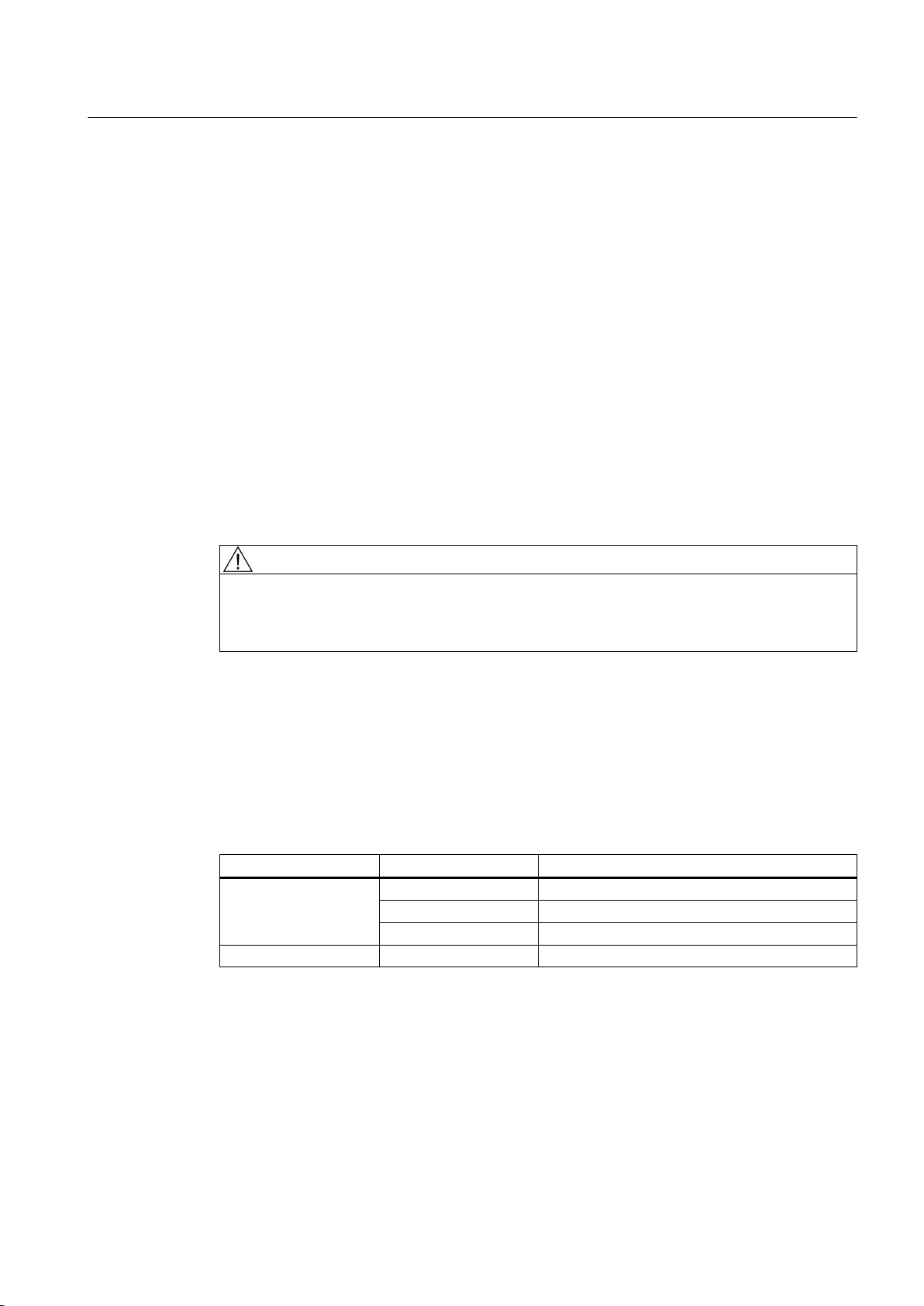
&2'(
,0
1R1
31N:
819
Q1PLQ
7+&/+
,1$
QPD[PLQ
6LHPHQV$*
0DGHLQ*HUPDQ\'1¾UQEHUJ
,(&(1
FRV˳
a0RW
,3
I1+]
Application range
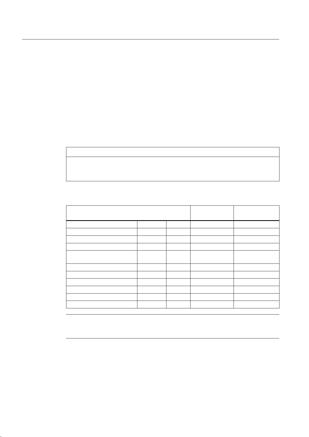
Rating plate
3
The motors of the 1PH818., 1PH822., 1PH828. series are used as industrial drives. They have
been designed to address a wide range of drive applications exclusively fed from converters.
They are characterized by their high power density, ruggedness, long lifetime, and overall
reliability.
WARNING
Risk of explosion
This machine is not designed for use in hazardous areas. An explosion can occur if the
machine is operated in these areas. This can result in death, serious injury or material damage.
Never operate this machine in hazardous areas.
The rating plate shows the identification data and the most important technical data. The data
on the rating plate and the contractual agreements define the limits of proper usage.
Figure 3-1 Schematic layout of rating plate
SIMOTICS M-1PH8 1PH818., 1PH822., 1PH828.
Operating Instructions 10/2017 21

Description
Table 3-1 Elements on the rating plate
No. Description No. Description
010 MLFB 200 Rated current IN (3)
012 Consecutive number, part of serial number 210 Rated power PN (3)
020 Serial number * 220 cos φ (3)
025 UL approval 230 Rated frequency fN (3)
026 (empty) 240 Rated speed nN (3)
030 Type of construction 250 Operating mode (3)
035 (empty) 255 Code for operating point 3
036 (empty) 260 Rated voltage VN (4)
040 Degree of protection 261 Switching mode 4
045 Type of balancing 270 Rated current IN (4)
050 Rated voltage UN (1) 280 Rated power PN (4)
051 Connection type 1 290 cos φ (4)
060 Rated current IN (1) 300 Rated frequency fN (4)
070 Rated power PN (1) 310 Rated speed nN (4)
080 cos φ (1) 320 Operating mode (4)
090 Rated frequency fN (1) 325 Code for operating point 4
100 Rated speed nN (1) 330 Maximum current I
MAX
110 Operating mode (1) 335 Weight
115 Code for operating point 1 340 Maximum torque M
120 Rated voltage UN (2) 350 Maximum speed n
MAX
MAX
121 Connection type 2 360 Temperature sensor
130 Rated current IN (2) 370 Tachometer/resolver
140 Rated power PN (2) 380 Cooling method
150 cos φ (2) 390 Throughput l/min (m3/s)
160 Rated frequency fN (2) 400 System pressure
170 Rated speed nN (2) 410 Maximum coolant temperature
180 Operating mode (2) 420 Options (I)
185 Code for operating point 2 430 Options (II)
190 Rated voltage UN (3) 440 Optional customer information
191 Connection type 3 450 Anti-condensation heater / place holder
* Based on the serial number, you can identify where the machine was manufactured and where you can
have your questions answered:
No:N... = Nuremberg
No.UC... = Frenstat
Rotor
This machine is an induction motor for low voltage with squirrel-cage induction motor and
integrated cooling circuit.
SIMOTICS M-1PH8 1PH818., 1PH822., 1PH828.
22 Operating Instructions 10/2017
Machine design
Description
The regulations and standards used as basis for designing and testing this machine are
stamped on the rating plate. The machine design basically complies with the subsequent
standards: Please refer to the EU Declaration of Conformity for the versions of the harmonized
standards referenced.
Table 3-2 Machine design
Feature Standard
Dimensions and operation characteristics IEC / EN 60034-1
Degree of protection IEC / EN 60034-5
Cooling IEC / EN 60034-6
Type of construction IEC / EN 60034-7
Terminal markings and direction of rotation IEC/EN 60034-8
Noise emission IEC / EN 60034-9
Mechanical vibrations IEC / EN 60034-14
IEC‑standard voltages IEC/DIN IEC 60038
Vibration limit values DIN ISO 10816-3
Relevant directives
The following directives are relevant for the SIMOTICS motor series.
European low-voltage directive
The SIMOTICS motor series complies with the requirements of the low-voltage directive
2014/35/EU.
European machinery directive
The SIMOTICS motor series does not fall within the area of validity of the machinery directive.
However, the use of the products in a typical machine application has been fully assessed for
compliance with the main regulations in this directive concerning health and safety.
European EMC Directive
The SIMOTICS motor series does not fall within the area of validity of the EMC directive. The
products are not considered as devices in the sense of the directive.
Eurasian conformity
The SIMOTICS motor series complies with the requirements of the Russia/Belarus/
Kazakhstan customs union (EAC).
China Compulsory Certification
The SIMOTICS motor series does not fall in the area of validity of the China Compulsory
Certification (CCC).
SIMOTICS M-1PH8 1PH818., 1PH822., 1PH828.
Operating Instructions 10/2017 23

Description
Drive
Underwriters Laboratories
The SIMOTICS motor series generally complies with UL and cUL requirements as component
of motor applications - and is correspondingly listed. Specifically developed motors and
functions are the exceptions in this case. Here, it is important that you carefully observe the
contents of the quotation and that there is a cUL mark on the rating plate (nameplate)!
Quality management system
Siemens AG employs a quality management system that meets the requirements of ISO 9001
and ISO 14001.
Certificates that can be downloaded
You can download certificates for the SIMOTICS motor series at the following link:
Certificates (https://support.industry.siemens.com/cs/ww/en/ps/13358/cert)
The motor speed is controlled using a converter.
NOTICE
Destruction of the machine when operated directly from the line supply
The machine will be destroyed if it is directly connected to the line supply. Only operate the
machine using a converter.
Types of construction
The motor is supplied with two attached lifting eyes. The type construction can be found on
the rating plate.
Vertical type of construction
For IM V5 and IM V15 types of construction with "shaft extension pointing downward", the
motor is equipped with two additional Vario eye bolts. The Vario eyebolts are in the terminal
box.
NOTICE
Protection against falling parts
For vertical types of construction, protect the air intake or discharge against falling parts, e.g.
by attaching a canopy. Otherwise the machine could be damaged.
SIMOTICS M-1PH8 1PH818., 1PH822., 1PH828.
24 Operating Instructions 10/2017
Cooling water-cooled motors
Cooling circuit
The cooling circuit consists of an enclosed, internal air circulation, which is driven by the shaft-
mounted fans and stainless steel tubes that are directly integrated into the laminated stator
core; cooling type IC 71W according to IEC / EN 60034‑6.
Cooling capacity
To ensure adequate cooling of the motor, it is essential to adhere to the specified cooling water
rate, temperature and cooling water quality (Page 29).
Cooling with external fan
The machine has cooling method IC 416 in accordance with IEC / EN 60034-6. The separately
driven fan unit and the terminal box can be mounted in a different position depending on the
order.
Description
See also
External fan
WARNING
Improper use of the external fan
Improper use of the external fan can result in death, serious injury, and material damage.
● Observe and follow the operating instructions of the external fan.
Additional documents (Page 167)
Different external fans are used depending on the shaft height and particular motor version:
Type Version External fan
1PH818.
1PH822.
1PH828. Standard version External fan with three-phase motor
Standard version EC external fan with single-phase EC motor
Version with option L75 External fan with three-phase motor
Version with option L76 EC external fan with three-phase EC motor
EC external fans with a fixed operating speed have been specifically designed for this motor
series.
Degree of protection
Depending on the version, the machine has degree of protection IP23 or IP55.
SIMOTICS M-1PH8 1PH818., 1PH822., 1PH828.
Operating Instructions 10/2017 25
Description
Supplementary devices
A temperature sensor is integrated in the stator winding to monitor the winding temperature.
The type of temperature sensor is specified on the rating plate.
Depending on the order options, various supplementary devices such as encoder systems can
be either installed or mounted.
Holding brake
Depending on the order, a special version of a holding brake from the Stromag company is
mounted. Various types of holding brake are mounted depending on the shaft height.
NOTICE
Technical data for the special version of the holding brake
The following technical data applies to the special version of the mounted holding brake. The
corresponding data in the manufacturers operating instructions do not apply.
Table 3-3 Technical data of the holding brake
Technical data NFF-A 63
AH180
Braking torque M
Max. speed n
Weight incl. hollow shaft m
Moment of inertia J
Total moment of inertia (emer‐
gency stop)
Rated voltage U [V] 230 V (AC) 230 V (AC)
Permitted single switched energy P [W] 98 210
Coil current I [A] 2,21 2,70
Number of emergency stops Z - 2100 1200
Opening time [ms] 300 300
Closing time [ms] 80 100
J
Brake
Brake
brake
brake
total
[Nm] 1000 1600
[rpm] 3500 3100
[kg] 63 88
[kgm2] 0,022 0,051
[kgm2] 1,3 3,9
NFF-A 100
AH225
Note
More information
● Commissioning (Page 87)
See also
Operating instructions, holding brake (Page 169)
SIMOTICS M-1PH8 1PH818., 1PH822., 1PH828.
26 Operating Instructions 10/2017

Ambient conditions
Roller bearings
Description
The standard machines are not suitable for use in corrosive atmospheres, atmospheres with
a high salt content, or outdoor applications.
The machines are equipped with different types of roller bearings depending on the version
and the operating conditions described in the order. If the machine is equipped with a
regreasing system, you will find the relevant data on the machine's lubricant plate.
The following standard roller bearing versions are available:
Table 3-4 Roller bearing versions
Design Bearings
Standard design and "Performance" Drive end deep-groove ball bearing as spring-loaded floating
bearing
Non-drive end deep-groove ball bearing as fixed bearing
Version for increased radial forces Drive end cylindrical-roller bearing as floating bearing
Non-drive end deep-groove ball bearing as fixed bearing
Paint finish
The machine is painted according to the instructions in your order.
SIMOTICS M-1PH8 1PH818., 1PH822., 1PH828.
Operating Instructions 10/2017 27

Description
SIMOTICS M-1PH8 1PH818., 1PH822., 1PH828.
28 Operating Instructions 10/2017

Preparations for use
Good planning and preparation of machine applications are essential in terms of keeping
installation simple and avoiding errors, ensuring safe operation, and allowing access to the
machine for servicing and corrective maintenance.
This chapter outlines what you need to consider when configuring your plant in relation to this
machine and the preparations you need to make before the machine is delivered.
4.1 Safety-related aspects to consider when configuring the plant
A number of residual risks are associated with the machine. These are described in the chapter
titled "Safety information" (Page 15) and in related sections.
Take appropriate safety precautions (covers, barriers, markings, etc.) to ensure the machine
is operated safely within your plant.
4.2 Observing the operating mode
Observe the machine's operating mode. Use a suitable control system to prevent overspeeds,
thus protecting the machine from damage.
4
4.3 Cooling water quality for water-cooled motors
The values specified for the cooling water correspond to the requirements for a closed cooling
circuit. Not all of the specified concentrations will occur in the cooling water at the same time.
A filter can be used to ensure smooth operation; the grade of filtration should not exceed
100 μm.
Cooling water specification
Table 4-1 Cooling water specification
Constituent Value
pH value 6.0 … 9.0
Total hardness < 170 ppm
Conductivity < 500 μS/cm
Chloride ions < 40 ppm
Sulfate ions < 50 ppm
Nitrate ions < 50 ppm
Dissolved solids < 340 ppm
Max. grain size < 100 μm
SIMOTICS M-1PH8 1PH818., 1PH822., 1PH828.
Operating Instructions 10/2017 29

Preparations for use
4.4 Ensuring cooling
Constituent Value
Operating pressure 6 bar max.
Inlet temperature < 30°C
Minimum cooling water inlet temperature T
Anti-freeze protection / corrosion protection 20 … 30 %
Inhibitor NALCO 00GE056 0.2 … 0,25 %
Cooling water intake temperature
The maximum cooling water intake temperature is 30 °C.
NOTICE
Condensation for an excessively low cooling water intake temperature
If the temperature difference between cooling water and ambient temperature is greater than
5 K, this may result in condensation forming in the machine. This results in material damage.
● Make sure that the condensation can drain away freely.
● Adopt appropriate measures to achieve the required intake temperature of the cooling
water.
● Alternatively, dry the ambient air.
cooling water
> T
ambient
- 5 K
4.4 Ensuring cooling
Note
Note also the technical data on the rating plates on the motor enclosure.
SIMOTICS M-1PH8 1PH818., 1PH822., 1PH828.
30 Operating Instructions 10/2017
 Loading...