

Siemens SIMOTICS M-1PH818, SIMOTICS M-1PH828, SIMOTICS M-1PH822 Operating And Installation Instructions
Page 1

www.siemens.com/drives
Operating Instructions
Installation Instructions
Main motors
SIMOTICS M-1PH8
Type 1PH818., 1PH822., 1PH828.
Edition 10/2017
Page 2

20.10.2017 15:09
V20.00
Page 3

Main motors
SIMOTICS M-1PH8
Type 1PH818., 1PH822., 1PH828.
Introduction
1
Operating Instructions
Installation Instructions
Safety information
Description
Preparations for use
Mounting
Electrical connection
Commissioning
Operation
2
3
4
5
6
7
8
Maintenance
Spare parts
Disposal
Service and Support
Technical specifications
Quality documents
Additional documents
9
10
11
A
B
C
D
Edition 10/2017
Page 4

Legal information
Warning notice system
This manual contains notices you have to observe in order to ensure your personal safety, as well as to prevent
damage to property. The notices referring to your personal safety are highlighted in the manual by a safety alert
symbol, notices referring only to property damage have no safety alert symbol. These notices shown below are
graded according to the degree of danger.
DANGER
indicates that death or severe personal injury will result if proper precautions are not taken.
WARNING
indicates that death or severe personal injury may result if proper precautions are not taken.
CAUTION
indicates that minor personal injury can result if proper precautions are not taken.
NOTICE
indicates that property damage can result if proper precautions are not taken.
If more than one degree of danger is present, the warning notice representing the highest degree of danger will be
used. A notice warning of injury to persons with a safety alert symbol may also include a warning relating to property
damage.
Qualified Personnel
The product/system described in this documentation may be operated only by personnel qualified for the specific
task in accordance with the relevant documentation, in particular its warning notices and safety instructions. Qualified
personnel are those who, based on their training and experience, are capable of identifying risks and avoiding
potential hazards when working with these products/systems.
Proper use of Siemens products
Note the following:
WARNING
Siemens products may only be used for the applications described in the catalog and in the relevant technical
documentation. If products and components from other manufacturers are used, these must be recommended or
approved by Siemens. Proper transport, storage, installation, assembly, commissioning, operation and
maintenance are required to ensure that the products operate safely and without any problems. The permissible
ambient conditions must be complied with. The information in the relevant documentation must be observed.
Trademarks
All names identified by ® are registered trademarks of Siemens AG. The remaining trademarks in this publication
may be trademarks whose use by third parties for their own purposes could violate the rights of the owner.
Disclaimer of Liability
We have reviewed the contents of this publication to ensure consistency with the hardware and software described.
Since variance cannot be precluded entirely, we cannot guarantee full consistency. However, the information in
this publication is reviewed regularly and any necessary corrections are included in subsequent editions.
Siemens AG
Process Industries and Drives
Postfach 48 48
90026 NÜRNBERG
GERMANY
Document order number: A5E35768675A AC
Ⓟ 10/2017 Subject to change
Copyright © Siemens AG 2017.
All rights reserved
Page 5

Table of contents
1 Introduction.................................................................................................................................................13
2 Safety information.......................................................................................................................................15
2.1 Information for the nominated person in control of the electrical installation.........................15
2.2 The five safety rules...............................................................................................................15
2.3 Qualified personnel................................................................................................................16
2.4 Safe handling.........................................................................................................................16
2.5 Electrostatic sensitive devices...............................................................................................18
2.6 Interference immunity.............................................................................................................19
2.7 Interference voltages when operating the converter..............................................................19
2.8 Electromagnetic fields when operating electrical power engineering installations.................20
3 Description..................................................................................................................................................21
4 Preparations for use...................................................................................................................................29
4.1 Safety-related aspects to consider when configuring the plant..............................................29
4.2 Observing the operating mode...............................................................................................29
4.3 Cooling water quality for water-cooled motors.......................................................................29
4.4 Ensuring cooling.....................................................................................................................30
4.5 Interlock circuit for the external fan........................................................................................33
4.6 Interlock circuit for anti-condensation heating (option)...........................................................33
4.7 Thermal motor protection.......................................................................................................34
4.8 Overheating during periodic duty...........................................................................................34
4.9 Noise emissions.....................................................................................................................34
4.10 Rotational speed limit values.................................................................................................35
4.11 System-inherent frequencies.................................................................................................35
4.12 Torsional loading of the drive train due to faults in the electrical supply................................35
4.13 Transport and storage............................................................................................................36
4.13.1 Checking the delivery.............................................................................................................36
4.13.2 Lifting and transportation........................................................................................................36
4.13.3 Transporting a force-ventilated motor that has already been in operation.............................40
4.13.4 Transporting a water-cooled motor that has already been in operation.................................40
4.13.5 Transporting the machine set.................................................................................................41
4.13.6 Storage...................................................................................................................................41
4.13.7 Attaching the rotor shipping brace prior to storage................................................................43
4.13.8 Protect the cooling water system of water-cooled motors......................................................44
4.13.9 Protection against corrosion...................................................................................................45
SIMOTICS M-1PH8 1PH818., 1PH822., 1PH828.
Operating Instructions 10/2017 5
Page 6

Table of contents
4.14 Converter operation...............................................................................................................45
4.14.1 Connecting to a converter......................................................................................................45
4.14.2 Insulated bearings for converter operation.............................................................................46
5 Mounting.....................................................................................................................................................49
5.1 Preparing for installation........................................................................................................49
5.1.1 Requirements for installation..................................................................................................49
5.1.2 Insulation resistance and polarization index..........................................................................50
5.1.3 Testing the insulation resistance and polarization index........................................................50
5.1.4 Prepare the mounting surfaces (IM B3).................................................................................53
5.1.5 Prepare the mounting surfaces (flange mounting).................................................................53
5.2 Lift the machine to where it will be mounted and position it...................................................53
5.2.1 Preconditions for correct alignment and secure attachment .................................................53
5.2.2 Checking the load handling attachments...............................................................................53
5.2.3 Removing anti-corrosion protection.......................................................................................54
5.2.4 Mounting the output elements................................................................................................54
5.2.5 Lifting and transporting the machine......................................................................................56
5.2.6 Open the condensation water drain holes (water-cooled motor)...........................................57
5.2.7 Open condensation drain holes (air-cooled motor, L12)........................................................58
5.2.8 Putting the machine down......................................................................................................59
5.2.9 Roughly aligning the machine................................................................................................59
5.3 Installing the machine............................................................................................................60
5.3.1 Selecting fixing screws...........................................................................................................60
5.3.2 Preconditions for smooth, vibration-free operation................................................................61
5.3.3 Vibration severity....................................................................................................................61
5.3.4 Aligning to the driven machine...............................................................................................62
5.3.5 Mounting the motor................................................................................................................64
5.4 Connecting the cooling water supply.....................................................................................64
5.5 Refitting the external fan........................................................................................................65
6 Electrical connection...................................................................................................................................67
6.1 Preparation.............................................................................................................................68
6.1.1 Selecting cables.....................................................................................................................68
6.1.2 Connect up the ground conductor..........................................................................................68
6.2 Connecting.............................................................................................................................69
6.2.1 Circuit diagram.......................................................................................................................69
6.2.2 Terminal designation..............................................................................................................69
6.2.3 Laying cables.........................................................................................................................70
6.2.4 Electrical connection data......................................................................................................70
6.2.5 Connection with cable lugs....................................................................................................71
6.2.6 Connecting aluminum conductors..........................................................................................73
6.2.7 Stepless mating face for the seal in the terminal box cover...................................................73
6.2.8 Performing connection operations.........................................................................................74
6.2.9 Internal equipotential bonding................................................................................................74
6.3 Auxiliary circuits.....................................................................................................................75
6.3.1 Selecting cables.....................................................................................................................75
6.3.2 Connecting an external fan....................................................................................................75
6.3.2.1 Connecting an EC external fan..............................................................................................77
6.3.2.2 Connecting an external fan with three-phase motor (option L75)..........................................78
SIMOTICS M-1PH8 1PH818., 1PH822., 1PH828.
6 Operating Instructions 10/2017
Page 7

Table of contents
6.3.2.3 Supply values for external fans with three-phase motor (option L75)....................................79
6.3.2.4 Attached air discharge throttle plate (option L75)..................................................................80
6.3.3 Connecting the speed encoder..............................................................................................82
6.3.4 Connect the holding brake.....................................................................................................83
6.3.5 Connecting the temperature sensor.......................................................................................83
6.3.6 Connecting to a converter......................................................................................................84
6.3.7 Converter operation on a grounded network..........................................................................85
7 Commissioning...........................................................................................................................................87
7.1 Insulation resistance and polarization index..........................................................................88
7.2 Checks to be carried out prior to commissioning ..................................................................89
7.3 Perform a test run with the water-cooled motor.....................................................................91
7.4 Switching on...........................................................................................................................91
7.5 Test run..................................................................................................................................92
7.6 Set values for monitoring the bearing temperature (optional)................................................93
8 Operation....................................................................................................................................................95
8.1 Safety guidelines in operation................................................................................................95
8.2 Do not operate water-cooled motors without cooling water...................................................97
8.3 Switching on the machine......................................................................................................97
8.4 Switching off water-cooled motors.........................................................................................98
8.5 Switching off force-ventilated motors.....................................................................................98
8.6 Switching on again after an emergency switching-off............................................................98
8.7 Stoppages..............................................................................................................................98
8.7.1 Avoidance of damage to roller bearings during stoppages....................................................99
8.8 Decommissioning the machine..............................................................................................99
8.9 Re-commissioning the machine...........................................................................................100
8.10 Faults...................................................................................................................................100
8.10.1 Inspections in the event of faults..........................................................................................100
8.10.2 Electrical faults at force-ventilated motors...........................................................................100
8.10.3 Electrical faults at water-cooled motors...............................................................................101
8.10.4 Mechanical faults.................................................................................................................102
8.10.5 Roller bearing faults.............................................................................................................103
8.10.6 Holding brake faults.............................................................................................................103
9 Maintenance.............................................................................................................................................105
9.1 Observe the operating instructions of the components........................................................105
9.2 Inspection and maintenance................................................................................................106
9.2.1 Inspections in the event of faults..........................................................................................107
9.2.2 Initial inspection....................................................................................................................107
9.2.3 Main inspection....................................................................................................................108
9.2.4 Regreasing intervals............................................................................................................109
9.2.5 Changing bearings when using permanently lubricated rolling-contact bearings................109
9.2.6 Maintenance.........................................................................................................................109
9.2.6.1 Measuring the insulation resistance during the course of maintenance work......................109
SIMOTICS M-1PH8 1PH818., 1PH822., 1PH828.
Operating Instructions 10/2017 7
Page 8

Table of contents
9.2.6.2 Maintenance intervals..........................................................................................................110
9.2.6.3 Rolling-contact bearings.......................................................................................................110
9.2.6.4 Lubrication............................................................................................................................110
9.2.6.5 Cleaning the spent grease chamber....................................................................................116
9.2.6.6 Maintaining the cooling water system..................................................................................116
9.2.6.7 Servicing the external fan.....................................................................................................117
9.2.6.8 Maintaining terminal boxes..................................................................................................118
9.3 Repair...................................................................................................................................119
9.3.1 Prepare servicing work.........................................................................................................119
9.3.2 Screws with preCOTE coating.............................................................................................120
9.3.3 Disassembling a water-cooled motor...................................................................................120
9.3.4 Dissembling a force-ventilated motor...................................................................................121
9.3.5 Removing and installing the protecting ring.........................................................................122
9.3.6 Removing and mounting the bearing shields.......................................................................123
9.3.7 Installing and sealing the motor...........................................................................................123
9.3.8 Sealing the motor (type 1PH828.)........................................................................................125
9.3.9 Relocating the external fan (type 1PH828.).........................................................................126
9.3.10 Removing and mounting the external fan............................................................................126
9.3.11 Removing and mounting the speed sensor..........................................................................128
9.3.12 Connecting the speed encoder............................................................................................130
9.3.13 Replacing the DRIVE-CLiQ interface (encoder module)......................................................130
9.3.14 Touch up any damaged paintwork.......................................................................................131
10 Spare parts...............................................................................................................................................133
10.1 Ordering data.......................................................................................................................133
10.2 Spare parts kits....................................................................................................................133
10.3 Holding brake.......................................................................................................................134
10.4 Ordering spare parts via the Internet...................................................................................134
10.5 Anti-condensation heating....................................................................................................134
10.6 Water-cooled motor..............................................................................................................135
10.6.1 Water-cooled motor, complete.............................................................................................135
10.6.2 Roller bearing cartridge DE with radial shaft sealing ring with regreasing...........................136
10.6.3 Rolling-contact bearing bush drive end, belt coupling..........................................................137
10.6.4 Rolling-contact bearing bush drive end, coupling output, with regreasing...........................138
10.6.5 Rolling-contact bearing bush drive end, coupling output, with permanent lubrication.........139
10.6.6 Rolling-contact bearing bush non-drive end, with permanent lubrication.............................140
10.6.7 Roller bearing cartridge NDE, with regreasing (type 1PH818., 1PH822.)............................141
10.6.8 Roller bearing cartridge NDE, with regreasing (type 1PH828.)............................................142
10.6.9 Rolling-contact bearing bush non-drive end "Performance"................................................143
10.7 Force-ventilated motor.........................................................................................................144
10.7.1 Force-ventilated motor, complete.........................................................................................144
10.7.2 External fan..........................................................................................................................145
10.7.3 External fan (option L75)......................................................................................................145
10.7.4 Roller bearing cartridge DE with radial shaft sealing ring with regreasing...........................146
10.7.5 Roller bearing cartridge DE, belt coupling............................................................................147
10.7.6 Roller bearing cartridge DE, coupling output, with regreasing.............................................148
10.7.7 Roller bearing cartridge DE, coupling output, with permanent lubrication...........................149
10.7.8 Roller bearing cartridge NDE, with permanent lubrication...................................................150
10.7.9 Roller bearing cartridge NDE, with regreasing (type 1PH818., 1PH822.)............................151
SIMOTICS M-1PH8 1PH818., 1PH822., 1PH828.
8 Operating Instructions 10/2017
Page 9

Table of contents
10.7.10 Roller bearing cartridge NDE, with regreasing (type 1PH828.)............................................152
10.7.11 Roller bearing cartridge NDE, "Performance"......................................................................153
10.8 Terminal box........................................................................................................................154
10.9 Speed encoder (type 1PH818., 1PH822.)............................................................................155
10.10 Speed encoder (type 1PH828.)............................................................................................156
11 Disposal....................................................................................................................................................157
11.1 RoHS - restricting the use of certain hazardous substances...............................................157
11.2 Preparing for disassembly....................................................................................................157
11.3 Dismantling the machine......................................................................................................158
11.4 Disposal of components.......................................................................................................158
A Service and Support.................................................................................................................................161
B Technical specifications............................................................................................................................163
B.1 Tightening torques for screw and bolt connections..............................................................163
C Quality documents....................................................................................................................................165
D Additional documents...............................................................................................................................167
D.1 Reader notes on the operating instructions of the holding brake.........................................167
D.2 Operating instructions, holding brake...................................................................................169
D.3 Operating instructions for the single-phase EC external fan, suction, SH180.....................193
D.4 Operating instructions for the single-phase EC external fan, suction, SH225.....................207
D.5 Operating instructions for the single-phase EC external fan, pressing, SH180...................221
D.6 Operating instructions for the single-phase EC external fan, pressing, SH225...................235
D.7 Operating instructions for the three-phase EC external fan, suction, SK180.......................249
D.8 Operating instructions for the three-phase EC external fan, suction, SK225.......................263
D.9 Operating instructions for the three-phase EC external fan, pressing, SH180....................279
D.10 Operating instructions for the three-phase EC external fan, pressing, SH225....................293
Index.........................................................................................................................................................309
Tables
Table 3-1 Elements on the rating plate........................................................................................................22
Table 3-2 Machine design ........................................................................................................................23
Table 3-3 Technical data of the holding brake............................................................................................26
Table 3-4 Roller bearing versions .............................................................................................................27
Table 4-1 Cooling water specification .......................................................................................................29
Table 4-2 Pressure drop in motors with pipe connection .........................................................................33
Table 4-3 Tightening torque and preloading force for axially fixing the rotor..............................................39
Table 5-1 Stator winding insulation resistance at 40° C..............................................................................51
SIMOTICS M-1PH8 1PH818., 1PH822., 1PH828.
Operating Instructions 10/2017 9
Page 10

Table of contents
Table 5-2 Maximum permitted radial vibration severity...............................................................................61
Table 5-3 Maximum permitted axial vibration severity................................................................................61
Table 5-4 Permissible deviations when aligning the motor.........................................................................63
Table 5-5 Rate of flow and pressure drop...................................................................................................65
Table 6-1 Terminal designations using the 1U1-1 as an example..............................................................69
Table 6-2 Data for electrical connection......................................................................................................71
Table 7-1 Minimum radial forces.................................................................................................................90
Table 7-2 Set values for monitoring the bearing temperatures before commissioning...............................93
Table 7-3 Set values for monitoring the bearing temperatures...................................................................93
Table 8-1 Electrical faults .......................................................................................................................101
Table 8-2 Electrical faults .......................................................................................................................101
Table 8-3 Mechanical faults.......................................................................................................................102
Table 8-4 Roller bearing faults .............................................................................................................103
Table 9-1 Checks after installation or repair .............................................................................................107
Table 9-2 Checks that must be performed during the main inspection.....................................................108
Table 9-3 Maintenance measures.............................................................................................................110
Table 9-4 Criteria for selecting roller bearing greases...............................................................................111
Table 9-5 Roller bearing greases for vertical and horizontal types of construction ..................................112
Table 9-6 Alternative greases with NLGI Class 2 for motors with a horizontal type of construction.........112
Table 9-7 Grease for the "Performance" version.......................................................................................113
Table 10-1 Motor, complete ........................................................................................................................135
Table 10-2 Spare parts for rolling-contact bearing bush drive end with mounted gearing, with
regreasing ................................................................................................................................136
Table 10-3 Spare parts for rolling-contact bearing bush drive end with belt coupling, with regreasing......137
Table 10-4 Spare parts for rolling-contact bearing bush drive end, with coupling output, with regreasing ....138
Table 10-5 Spare parts for rolling-contact bearing bush drive end, with coupling output, with permanent
lubrication .................................................................................................................................139
Table 10-6 Spare parts for rolling-contact bearing bush non-drive end, permanent lubrication .................140
Table 10-7 Spare part, roller bearing cartridge NDE, with regreasing (type 1PH818., 1PH822.) ..............141
Table 10-8 Spare part, roller bearing cartridge NDE, with regreasing (type 1PH828.)...............................142
Table 10-9 Spare parts for rolling-contact bearing bush non-drive end with regreasing.............................143
Table 10-10 Motor, complete .......................................................................................................................144
Table 10-11 Spare parts for external fan.......................................................................................................145
Table 10-12 Spare parts for rolling-contact bearing bush drive end with mounted gearing, with
regreasing ................................................................................................................................146
Table 10-13 Spare parts for rolling-contact bearing bush drive end with belt coupling, with regreasing......147
Table 10-14 Spare parts for rolling-contact bearing bush drive end, with coupling output, with regreasing ....148
Table 10-15 Spare parts for rolling-contact bearing bush drive end, with coupling output, with permanent
lubrication .................................................................................................................................149
Table 10-16 Spare parts for roller bearing cartridge, non-drive end, permanent lubrication ........................150
Table 10-17 Spare part, roller bearing cartridge NDE, with regreasing (type 1PH818., 1PH822.) ..............151
SIMOTICS M-1PH8 1PH818., 1PH822., 1PH828.
10 Operating Instructions 10/2017
Page 11

Table of contents
Table 10-18 Spare part, roller bearing cartridge NDE, with regreasing (type 1PH828.) ..............................152
Table 10-19 Spare parts for rolling-contact bearing bush non-drive end with regreasing.............................153
Table 10-20 Spare parts for terminal box .....................................................................................................154
Table 10-21 Spare part, speed encoder (type 1PH818., 1PH822.) ..............................................................155
Table 10-22 Spare part, speed encoder (type 1PH828.) ............................................................................156
Table B-1 Tightening torques for screw/bolt connections with a tolerance of ±10%.................................163
Table D-1 Technical data of the holding brake..........................................................................................167
Figures
Figure 3-1 Schematic layout of rating plate..................................................................................................21
Figure 4-1 Air guidance from the DE to the NDE (schematic representation, types 1PH818. and
1PH822.).....................................................................................................................................31
Figure 4-2 Bypass for 1PH822. for IP23 ......................................................................................................32
Figure 4-3 Air guidance from the NDE to the DE (schematic representation, type 1PH828.) for IP55........32
Figure 4-4 Lifting the machine (schematic representation)...........................................................................38
Figure 4-5 Rotor shipping brace...................................................................................................................39
Figure 4-6 Schematic representation of a single drive.................................................................................46
Figure 5-1 Balancing type on the drive-end side..........................................................................................54
Figure 5-2 Water drain holes........................................................................................................................58
Figure 5-3 Water drain holes, for types 1PH818., 1PH822..........................................................................58
Figure 5-4 Max. permissible vibration velocity, taking into account the vibration displacement and
vibration acceleration..................................................................................................................62
Figure 5-5 Aligning the motor.......................................................................................................................63
Figure 6-1 Terminal lug ① for the grounding conductor for a force-ventilated motor..................................68
Figure 6-2 Terminal lug ① for the grounding conductor for a water-cooled motor......................................69
Figure 6-3 External fan terminal box ① (schematic representation)............................................................77
Figure 6-4 External fan terminal box ① (schematic representation)............................................................78
Figure 6-5 Throttle plate for suction-type ventilation (DE to NDE)................................................................81
Figure 6-6 Throttle plate for forced-draft ventilation (NDE to DE).................................................................81
Figure 6-7 Detailed view: Plug-in connection ..............................................................................................82
Figure 6-8 Sensor Module ① mounted on the terminal box........................................................................83
Figure 9-1 Flat grease nipples ① and ②, schematic representation for types 1PH818. and 1PH822. ....115
Figure 9-2 Flat grease nipple ① and ② (schematic representation for type 1PH828.)............................116
Figure 9-3 Fitting the protecting ring...........................................................................................................123
Figure 9-4 Sealing gap between the enclosure and bearing shields (schematic representation)..............125
Figure 9-5 Installing the rotary shaft seal....................................................................................................126
Figure 9-6 Unscrewing the external fan (1PH818., 1PH822.)....................................................................127
Figure 9-7 Unscrewing the external fan (1PH828.)....................................................................................127
Figure 9-8 Detailed view of the speed encoder..........................................................................................128
SIMOTICS M-1PH8 1PH818., 1PH822., 1PH828.
Operating Instructions 10/2017 11
Page 12

Table of contents
Figure 9-9 Electrical connection of the speed sensor ................................................................................130
Figure 10-1 Schematic diagram of motor (complete)...................................................................................135
Figure 10-2 Rolling-contact bearing bush drive end with mounted gearing, with regreasing.......................136
Figure 10-3 Rolling-contact bearing bush drive end with belt coupling, with regreasing..............................137
Figure 10-4 Rolling-contact bearing bush drive end, with coupling output, with regreasing.........................138
Figure 10-5 Rolling-contact bearing bush drive end, with coupling output, with permanent lubrication.......139
Figure 10-6 Rolling-contact bearing bush non-drive end, permanent lubrication ........................................140
Figure 10-7 Roller bearing cartridge NDE, with regreasing (type 1PH818., 1PH822.).................................141
Figure 10-8 Roller bearing cartridge NDE, with regreasing (type 1PH828.).................................................142
Figure 10-9 Rolling-contact bearing bush non-drive end with regreasing ...................................................143
Figure 10-10 Schematic representation of the motor, complete.....................................................................144
Figure 10-11 Spare parts for external fan (type 1PH818., 1PH822.) ............................................................145
Figure 10-12 Rolling-contact bearing bush drive end with mounted gearing, with regreasing.......................146
Figure 10-13 Rolling-contact bearing bush drive end with belt coupling, with regreasing..............................147
Figure 10-14 Rolling-contact bearing bush drive end, with coupling output, with regreasing.........................148
Figure 10-15 Rolling-contact bearing bush drive end, with coupling output, with permanent lubrication.......149
Figure 10-16 Roller bearing cartridge, non-drive end, permanent lubrication ...............................................150
Figure 10-17 Roller bearing cartridge NDE, with regreasing (type 1PH818., 1PH822.).................................151
Figure 10-18 Roller bearing cartridge NDE, with regreasing (type 1PH828.).................................................152
Figure 10-19 Rolling-contact bearing bush non-drive end with regreasing ...................................................153
Figure 10-20 Terminal box..............................................................................................................................154
Figure 10-21 Speed encoder..........................................................................................................................155
Figure 10-22 Speed encoder (type 1PH828.).................................................................................................156
SIMOTICS M-1PH8 1PH818., 1PH822., 1PH828.
12 Operating Instructions 10/2017
Page 13

Introduction
These operating instructions are valid for 1PH8 induction motors in shaft heights 180 ... 280
in a force-ventilated or water-cooled version.
● 1PH818.1 and 1PH818.3
● 1PH822.1 and 1PH822.3
● 1PH828.1
The serial number of the motor can be found on the rating plate.
These instructions describe the machine and explain how to handle it, from initial delivery to
final disposal of the equipment. Keep these instructions for later use.
Read these operating instructions before you handle the machine and follow the instructions
to become familiar with its design and operating principles and thus ensure safe, problem-free
machine operation and long service life.
Please contact the Service Center (Page 161) if you have any suggestions on how to improve
this document.
Text format features
1
The warning notice system is explained on the rear of the inside front. Always follow the safety
instructions and notices in these instructions.
In addition to the safety-related warning notices which you must read, you will find the text in
these instructions is formatted in the following way:
1. Handling instructions are always formatted as a numbered list. Always perform the steps
in the order given.
● Lists are formatted as bulleted lists.
– Lists on the second level are hyphenated.
Note
A Note is an important item of information about the product, handling of the product or the
relevant section of the document. Notes provide you with help or further suggestions/ideas.
SIMOTICS M-1PH8 1PH818., 1PH822., 1PH828.
Operating Instructions 10/2017 13
Page 14

Introduction
SIMOTICS M-1PH8 1PH818., 1PH822., 1PH828.
14 Operating Instructions 10/2017
Page 15

Safety information
2.1 Information for the nominated person in control of the electrical installation
This electric machine has been designed and built in accordance with the specifications
contained in Directive 2014/35/EU ("Low-Voltage Directive") and is intended for use in
industrial plants. Please observe the country-specific regulations when using the electric
machine outside the European Community. Follow the local and industry-specific safety and
setup regulations.
The persons responsible for the plant must ensure the following:
● Planning and configuration work and all work carried out on and with the machine is only
to be done by qualified personnel.
● The operating instructions must always be available for all work.
● The technical data as well as the specifications relating to the permissible installation,
connection, ambient and operating conditions are taken into account at all times.
● The specific setup and safety regulations as well as regulations on the use of personal
protective equipment are observed.
Note
2
Use the services and support provided by the appropriate Service Center (Page 161) for
planning, installation, commissioning, and servicing work.
You will find safety instructions in the individual sections of this document. Follow the safety
instructions for your own safety, to protect other people and to avoid damage to property.
Observe the following safety instructions for all activities on and with the machine.
2.2 The five safety rules
For your own personal safety and to prevent material damage when carrying out any work,
always observe the safety-relevant instructions and the following five safety rules according
to EN 50110‑1 "Working in a voltage-free state". Apply the five safety rules in the sequence
stated before starting work.
Five safety rules
1. Disconnect the system.
Also disconnect the auxiliary circuits, for example, anti-condensation heating.
2. Secure against reconnection.
3. Verify absence of operating voltage.
SIMOTICS M-1PH8 1PH818., 1PH822., 1PH828.
Operating Instructions 10/2017 15
Page 16

Safety information
2.3 Qualified personnel
4. Ground and short-circuit.
5. Provide protection against adjacent live parts.
To energize the system, apply the measures in reverse order.
2.3 Qualified personnel
All work at the machine must be carried out by qualified personnel only. For the purpose of
this documentation, qualified personnel is taken to mean people who fulfill the following
requirements:
● Through appropriate training and experience, they are able to recognize and avoid risks
and potential dangers in their particular field of activity.
● They have been instructed to carry out work on the machine by the appropriate person
responsible.
2.4 Safe handling
Workplace safety depends on the attentiveness, care, and common sense of the personnel
who install, operate, and maintain the machine. In addition to the safety measures cited, as a
matter of principle, the use of caution is necessary when you are near the machine. Always
pay attention to your safety.
Also observe the following to prevent accidents:
● General safety regulations applicable in the country where the machine is deployed.
● Manufacturer-specific and application-specific regulations
● Special agreements made with the operator
● Separate safety instructions supplied with the machine
● Safety symbols and instructions on the machine and its packaging
WARNING
Live parts
Electric machines contain live parts.
Fatal or severe injuries and substantial material damage can occur if the covers are removed
or if the machine is not handled, operated, or maintained properly.
● Always observe the “five safety rules" (Page 15) when carrying out any work on the
machine.
● Only remove the covers using the methods described by these operating instructions.
● Operate the machine properly.
● Regularly and correctly maintain the machine.
SIMOTICS M-1PH8 1PH818., 1PH822., 1PH828.
16 Operating Instructions 10/2017
Page 17

Safety information
2.4 Safe handling
WARNING
Rotating parts
Electric machines contain dangerous rotating parts.
Fatal or severe injuries and substantial material damage can occur if the covers are removed
or if the machine is not handled, operated, or maintained properly.
● Only remove the covers using the methods described by these operating instructions.
● Operate the machine properly.
● Regularly and correctly maintain the machine.
● Secure free-standing shaft ends and other rotating parts such as couplings, belt pulleys
etc. against touch.
WARNING
Hot surfaces
Electric machines have hot surfaces. Do not touch these surfaces. They could cause burns.
● Allow the machine to cool before starting work on the machine.
● Only remove the covers using the methods described by these operating instructions.
● Operate the machine properly.
CAUTION
Hazardous substances
Chemical substances required for the setup, operation and maintenance of machines can
present a health risk.
Poisoning, skin damage, cauterization of the respiratory tract, and other health damage may
result.
● Read the information in these operating instructions and the product information supplied
by the manufacturer.
● Observe the relevant safety regulations and wear the personal protective equipment
specified.
CAUTION
Flammable substances
Chemical substances required for the setup, operation and maintenance of machines may
be flammable.
Burns and other damage to health and material may result.
● Read the information in these operating instructions and the product information supplied
by the manufacturer.
● Observe the relevant safety regulations and wear the personal protective equipment
specified.
SIMOTICS M-1PH8 1PH818., 1PH822., 1PH828.
Operating Instructions 10/2017 17
Page 18

Safety information
2.5 Electrostatic sensitive devices
WARNING
Noise emissions
During operation, the machine's noise emission levels can exceed those permitted at the
workplace, which can cause hearing damage.
Take steps to reduce noise, such as introducing covers and protective insulation or adopting
hearing protection measures, so that the machine can be operated safely within your system.
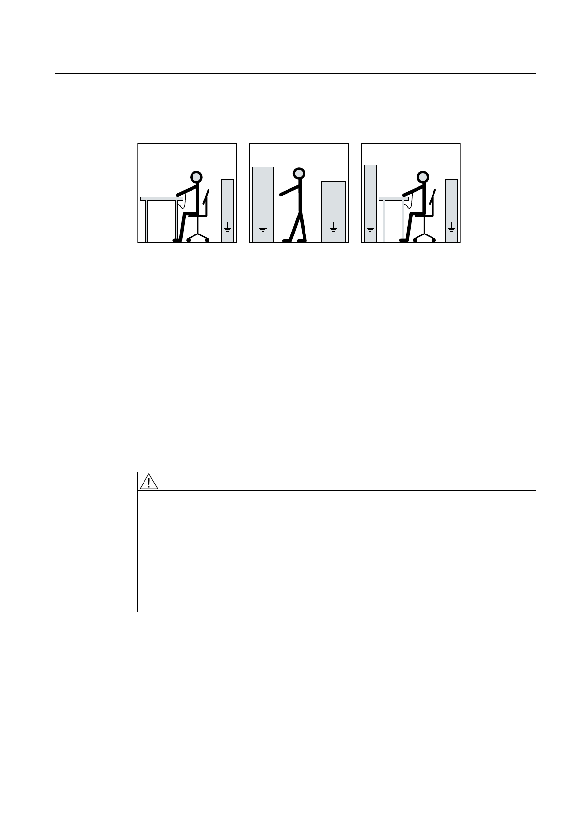
2.5 Electrostatic sensitive devices
Material damage due to electrostatic discharge
Electronic modules contain components that can be destroyed by electrostatic discharge.
These components can be damaged or destroyed if they are not handled correctly. To protect
equipment against damage, follow the instructions given below.
● Only touch electronic modules if you absolutely have to work on them.
● The body of the person concerned must have been electrostatically discharged and
grounded immediately before any electronic modules are touched.
● Electronic modules should not be brought into contact with electrically insulating materials,
such as:
– Plastic film
– Plastic parts
– Insulating table supports
– Clothing made of synthetic fibers
● Always place electrostatic sensitive devices on conductive bases.
● Always pack, store and transport electronic modules or components in conductive
packaging, such as:
– Metallized plastic or metal containers
– Conductive foam material
– Domestic aluminum foil
SIMOTICS M-1PH8 1PH818., 1PH822., 1PH828.
18 Operating Instructions 10/2017
Page 19
6HDWLQJSRVLWLRQ
6WDQGLQJSRVLWLRQ
6WDQGLQJVHDWLQJSRVLWLRQ
EE
D
F
D
IIIII
D
FF
H
GG
H
G
See also
Safety information
2.6 Interference immunity
The necessary ESD protective measures for electrostatic sensitive devices are illustrated once
again in the following drawings:
a = conductive floor surfaceb = ESD table c = ESD shoes
d = ESD overall e = ESD wristband f = cabinet ground connection
Replacing the DRIVE-CLiQ interface (encoder module) (Page 130)
2.6 Interference immunity
By selecting suitable signal cables and evaluation units, companies operating complete plants
and systems must ensure that the interference immunity of the machine is not diminished.
2.7 Interference voltages when operating the converter
WARNING
Interference voltages when operating the converter
When a converter is in operation, the emitted interference varies in strength depending on
the converter (manufacturer, type, interference suppression measures undertaken). On
machines with integrated sensors (e.g. PTC thermistors), interference voltages caused by
the converter may occur on the sensor lead. This can cause faults which can result in eventual
or immediate death, serious injury or material damage.
Observe the EMC instructions of the converter manufacturer in order to avoid exceeding the
limit values according to IEC/EN 61000-6-3 for drive systems comprising machine and
converter. You must put appropriate EMC measures in place.
SIMOTICS M-1PH8 1PH818., 1PH822., 1PH828.
Operating Instructions 10/2017 19
Page 20

Safety information
2.8 Electromagnetic fields when operating electrical power engineering installations
2.8 Electromagnetic fields when operating electrical power engineering
installations
WARNING
Interference to electronic devices caused by electrical power equipment
Electrical power equipment generate electric fields during operation. Potentially lethal
malfunctions can occur in medical implants, e.g. pacemakers, in the vicinity of electrical power
equipment. Data may be lost on magnetic or electronic data carriers.
● It is forbidden for people with pacemakers to enter the vicinity of the machine.
● Protect the personnel working in the plant by taking appropriate measures, such as
erecting identifying markings, safety barriers and warning signs and giving safety talks.
● Observe the nationally applicable health and safety regulations.
● Do not carry any magnetic or electronic data media.
SIMOTICS M-1PH8 1PH818., 1PH822., 1PH828.
20 Operating Instructions 10/2017
Page 21
Description
&2'(
,0
1R1
31N:
819
Q1PLQ
7+&/+
,1$
QPD[PLQ
6LHPHQV$*
0DGHLQ*HUPDQ\'1¾UQEHUJ
,(&(1
FRV˳
a0RW
,3
I1+]
Application range
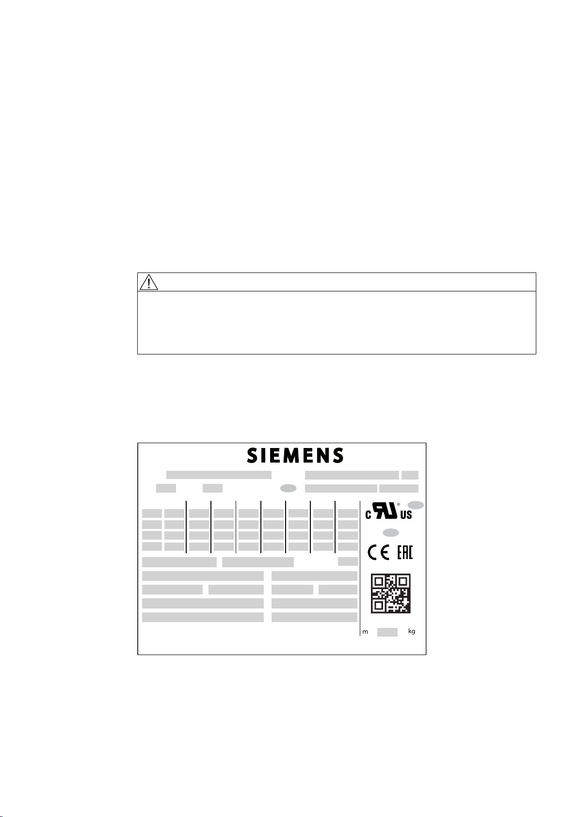
Rating plate
3
The motors of the 1PH818., 1PH822., 1PH828. series are used as industrial drives. They have
been designed to address a wide range of drive applications exclusively fed from converters.
They are characterized by their high power density, ruggedness, long lifetime, and overall
reliability.
WARNING
Risk of explosion
This machine is not designed for use in hazardous areas. An explosion can occur if the
machine is operated in these areas. This can result in death, serious injury or material damage.
Never operate this machine in hazardous areas.
The rating plate shows the identification data and the most important technical data. The data
on the rating plate and the contractual agreements define the limits of proper usage.
Figure 3-1 Schematic layout of rating plate
SIMOTICS M-1PH8 1PH818., 1PH822., 1PH828.
Operating Instructions 10/2017 21
Page 22

Description
Table 3-1 Elements on the rating plate
No. Description No. Description
010 MLFB 200 Rated current IN (3)
012 Consecutive number, part of serial number 210 Rated power PN (3)
020 Serial number * 220 cos φ (3)
025 UL approval 230 Rated frequency fN (3)
026 (empty) 240 Rated speed nN (3)
030 Type of construction 250 Operating mode (3)
035 (empty) 255 Code for operating point 3
036 (empty) 260 Rated voltage VN (4)
040 Degree of protection 261 Switching mode 4
045 Type of balancing 270 Rated current IN (4)
050 Rated voltage UN (1) 280 Rated power PN (4)
051 Connection type 1 290 cos φ (4)
060 Rated current IN (1) 300 Rated frequency fN (4)
070 Rated power PN (1) 310 Rated speed nN (4)
080 cos φ (1) 320 Operating mode (4)
090 Rated frequency fN (1) 325 Code for operating point 4
100 Rated speed nN (1) 330 Maximum current I
MAX
110 Operating mode (1) 335 Weight
115 Code for operating point 1 340 Maximum torque M
120 Rated voltage UN (2) 350 Maximum speed n
MAX
MAX
121 Connection type 2 360 Temperature sensor
130 Rated current IN (2) 370 Tachometer/resolver
140 Rated power PN (2) 380 Cooling method
150 cos φ (2) 390 Throughput l/min (m3/s)
160 Rated frequency fN (2) 400 System pressure
170 Rated speed nN (2) 410 Maximum coolant temperature
180 Operating mode (2) 420 Options (I)
185 Code for operating point 2 430 Options (II)
190 Rated voltage UN (3) 440 Optional customer information
191 Connection type 3 450 Anti-condensation heater / place holder
* Based on the serial number, you can identify where the machine was manufactured and where you can
have your questions answered:
No:N... = Nuremberg
No.UC... = Frenstat
Rotor
This machine is an induction motor for low voltage with squirrel-cage induction motor and
integrated cooling circuit.
SIMOTICS M-1PH8 1PH818., 1PH822., 1PH828.
22 Operating Instructions 10/2017
Page 23
Machine design
Description
The regulations and standards used as basis for designing and testing this machine are
stamped on the rating plate. The machine design basically complies with the subsequent
standards: Please refer to the EU Declaration of Conformity for the versions of the harmonized
standards referenced.
Table 3-2 Machine design
Feature Standard
Dimensions and operation characteristics IEC / EN 60034-1
Degree of protection IEC / EN 60034-5
Cooling IEC / EN 60034-6
Type of construction IEC / EN 60034-7
Terminal markings and direction of rotation IEC/EN 60034-8
Noise emission IEC / EN 60034-9
Mechanical vibrations IEC / EN 60034-14
IEC‑standard voltages IEC/DIN IEC 60038
Vibration limit values DIN ISO 10816-3
Relevant directives
The following directives are relevant for the SIMOTICS motor series.
European low-voltage directive
The SIMOTICS motor series complies with the requirements of the low-voltage directive
2014/35/EU.
European machinery directive
The SIMOTICS motor series does not fall within the area of validity of the machinery directive.
However, the use of the products in a typical machine application has been fully assessed for
compliance with the main regulations in this directive concerning health and safety.
European EMC Directive
The SIMOTICS motor series does not fall within the area of validity of the EMC directive. The
products are not considered as devices in the sense of the directive.
Eurasian conformity
The SIMOTICS motor series complies with the requirements of the Russia/Belarus/
Kazakhstan customs union (EAC).
China Compulsory Certification
The SIMOTICS motor series does not fall in the area of validity of the China Compulsory
Certification (CCC).
SIMOTICS M-1PH8 1PH818., 1PH822., 1PH828.
Operating Instructions 10/2017 23
Page 24

Description
Drive
Underwriters Laboratories
The SIMOTICS motor series generally complies with UL and cUL requirements as component
of motor applications - and is correspondingly listed. Specifically developed motors and
functions are the exceptions in this case. Here, it is important that you carefully observe the
contents of the quotation and that there is a cUL mark on the rating plate (nameplate)!
Quality management system
Siemens AG employs a quality management system that meets the requirements of ISO 9001
and ISO 14001.
Certificates that can be downloaded
You can download certificates for the SIMOTICS motor series at the following link:
Certificates (https://support.industry.siemens.com/cs/ww/en/ps/13358/cert)
The motor speed is controlled using a converter.
NOTICE
Destruction of the machine when operated directly from the line supply
The machine will be destroyed if it is directly connected to the line supply. Only operate the
machine using a converter.
Types of construction
The motor is supplied with two attached lifting eyes. The type construction can be found on
the rating plate.
Vertical type of construction
For IM V5 and IM V15 types of construction with "shaft extension pointing downward", the
motor is equipped with two additional Vario eye bolts. The Vario eyebolts are in the terminal
box.
NOTICE
Protection against falling parts
For vertical types of construction, protect the air intake or discharge against falling parts, e.g.
by attaching a canopy. Otherwise the machine could be damaged.
SIMOTICS M-1PH8 1PH818., 1PH822., 1PH828.
24 Operating Instructions 10/2017
Page 25
Cooling water-cooled motors
Cooling circuit
The cooling circuit consists of an enclosed, internal air circulation, which is driven by the shaft-
mounted fans and stainless steel tubes that are directly integrated into the laminated stator
core; cooling type IC 71W according to IEC / EN 60034‑6.
Cooling capacity
To ensure adequate cooling of the motor, it is essential to adhere to the specified cooling water
rate, temperature and cooling water quality (Page 29).
Cooling with external fan
The machine has cooling method IC 416 in accordance with IEC / EN 60034-6. The separately
driven fan unit and the terminal box can be mounted in a different position depending on the
order.
Description
See also
External fan
WARNING
Improper use of the external fan
Improper use of the external fan can result in death, serious injury, and material damage.
● Observe and follow the operating instructions of the external fan.
Additional documents (Page 167)
Different external fans are used depending on the shaft height and particular motor version:
Type Version External fan
1PH818.
1PH822.
1PH828. Standard version External fan with three-phase motor
Standard version EC external fan with single-phase EC motor
Version with option L75 External fan with three-phase motor
Version with option L76 EC external fan with three-phase EC motor
EC external fans with a fixed operating speed have been specifically designed for this motor
series.
Degree of protection
Depending on the version, the machine has degree of protection IP23 or IP55.
SIMOTICS M-1PH8 1PH818., 1PH822., 1PH828.
Operating Instructions 10/2017 25
Page 26

Description
Supplementary devices
A temperature sensor is integrated in the stator winding to monitor the winding temperature.
The type of temperature sensor is specified on the rating plate.
Depending on the order options, various supplementary devices such as encoder systems can
be either installed or mounted.
Holding brake
Depending on the order, a special version of a holding brake from the Stromag company is
mounted. Various types of holding brake are mounted depending on the shaft height.
NOTICE
Technical data for the special version of the holding brake
The following technical data applies to the special version of the mounted holding brake. The
corresponding data in the manufacturers operating instructions do not apply.
Table 3-3 Technical data of the holding brake
Technical data NFF-A 63
AH180
Braking torque M
Max. speed n
Weight incl. hollow shaft m
Moment of inertia J
Total moment of inertia (emer‐
gency stop)
Rated voltage U [V] 230 V (AC) 230 V (AC)
Permitted single switched energy P [W] 98 210
Coil current I [A] 2,21 2,70
Number of emergency stops Z - 2100 1200
Opening time [ms] 300 300
Closing time [ms] 80 100
J
Brake
Brake
brake
brake
total
[Nm] 1000 1600
[rpm] 3500 3100
[kg] 63 88
[kgm2] 0,022 0,051
[kgm2] 1,3 3,9
NFF-A 100
AH225
Note
More information
● Commissioning (Page 87)
See also
Operating instructions, holding brake (Page 169)
SIMOTICS M-1PH8 1PH818., 1PH822., 1PH828.
26 Operating Instructions 10/2017
Page 27

Ambient conditions
Roller bearings
Description
The standard machines are not suitable for use in corrosive atmospheres, atmospheres with
a high salt content, or outdoor applications.
The machines are equipped with different types of roller bearings depending on the version
and the operating conditions described in the order. If the machine is equipped with a
regreasing system, you will find the relevant data on the machine's lubricant plate.
The following standard roller bearing versions are available:
Table 3-4 Roller bearing versions
Design Bearings
Standard design and "Performance" Drive end deep-groove ball bearing as spring-loaded floating
bearing
Non-drive end deep-groove ball bearing as fixed bearing
Version for increased radial forces Drive end cylindrical-roller bearing as floating bearing
Non-drive end deep-groove ball bearing as fixed bearing
Paint finish
The machine is painted according to the instructions in your order.
SIMOTICS M-1PH8 1PH818., 1PH822., 1PH828.
Operating Instructions 10/2017 27
Page 28

Description
SIMOTICS M-1PH8 1PH818., 1PH822., 1PH828.
28 Operating Instructions 10/2017
Page 29

Preparations for use
Good planning and preparation of machine applications are essential in terms of keeping
installation simple and avoiding errors, ensuring safe operation, and allowing access to the
machine for servicing and corrective maintenance.
This chapter outlines what you need to consider when configuring your plant in relation to this
machine and the preparations you need to make before the machine is delivered.
4.1 Safety-related aspects to consider when configuring the plant
A number of residual risks are associated with the machine. These are described in the chapter
titled "Safety information" (Page 15) and in related sections.
Take appropriate safety precautions (covers, barriers, markings, etc.) to ensure the machine
is operated safely within your plant.
4.2 Observing the operating mode
Observe the machine's operating mode. Use a suitable control system to prevent overspeeds,
thus protecting the machine from damage.
4
4.3 Cooling water quality for water-cooled motors
The values specified for the cooling water correspond to the requirements for a closed cooling
circuit. Not all of the specified concentrations will occur in the cooling water at the same time.
A filter can be used to ensure smooth operation; the grade of filtration should not exceed
100 μm.
Cooling water specification
Table 4-1 Cooling water specification
Constituent Value
pH value 6.0 … 9.0
Total hardness < 170 ppm
Conductivity < 500 μS/cm
Chloride ions < 40 ppm
Sulfate ions < 50 ppm
Nitrate ions < 50 ppm
Dissolved solids < 340 ppm
Max. grain size < 100 μm
SIMOTICS M-1PH8 1PH818., 1PH822., 1PH828.
Operating Instructions 10/2017 29
Page 30

Preparations for use
4.4 Ensuring cooling
Constituent Value
Operating pressure 6 bar max.
Inlet temperature < 30°C
Minimum cooling water inlet temperature T
Anti-freeze protection / corrosion protection 20 … 30 %
Inhibitor NALCO 00GE056 0.2 … 0,25 %
Cooling water intake temperature
The maximum cooling water intake temperature is 30 °C.
NOTICE
Condensation for an excessively low cooling water intake temperature
If the temperature difference between cooling water and ambient temperature is greater than
5 K, this may result in condensation forming in the machine. This results in material damage.
● Make sure that the condensation can drain away freely.
● Adopt appropriate measures to achieve the required intake temperature of the cooling
water.
● Alternatively, dry the ambient air.
cooling water
> T
ambient
- 5 K
4.4 Ensuring cooling
Note
Note also the technical data on the rating plates on the motor enclosure.
SIMOTICS M-1PH8 1PH818., 1PH822., 1PH828.
30 Operating Instructions 10/2017
Page 31

Preconditions for adequate cooling
● For motors that are cooled by the ambient air, the cooling air must be able to flow unimpeded
to and from the motors. Hot discharged air should not be drawn in again.
NOTICE
Overheating
If the required cooling air flow cannot be maintained, the machine can overheat. This can
result in material damage.
● Maintain the required minimum clearance for customer-supplied mounted accessories
at the air intake opening and at the air discharge openings to ensure the required
cooling air flow.
● Comply with the conditions of the IP degree of protection.
More stringent requirements regarding the IP degree of protection may necessitate the
installation of suitable filters and special arrangement of the intake and outlet openings.
● Equipment and cables must be connected without strain.
Preparations for use
4.4 Ensuring cooling
Figure 4-1 Air guidance from the DE to the NDE (schematic representation, types 1PH818. and
1PH822.)
A bypass is available for 1PH822. with IP23 degree of protection and air guidance from the
DE to the NDE.
SIMOTICS M-1PH8 1PH818., 1PH822., 1PH828.
Operating Instructions 10/2017 31
Page 32

Preparations for use
4.4 Ensuring cooling
Figure 4-2 Bypass for 1PH822. for IP23
Figure 4-3 Air guidance from the NDE to the DE (schematic representation, type 1PH828.) for IP55
External fan
The code for the external fan is at the eleventh position of the order number. The order number
– and therefore the installed external fan type – is specified on the rating plate.
Machines with pipe connection
You must mount and connect pipes and a fan of suitable type and dimensioning to machines
that are intended for the connection of pipes and/or for operation with an external fan.
Please observe the following when connecting pipes:
● Additional pressure drop in the system.
● Shipping covers on the ventilation openings must have been removed.
SIMOTICS M-1PH8 1PH818., 1PH822., 1PH828.
32 Operating Instructions 10/2017
Page 33

Preparations for use
4.5 Interlock circuit for the external fan
For machines with a pipe connection, the potential pressure drop inside the machine is given
in the following table:
Table 4-2 Pressure drop in motors with pipe connection
Type Degree of pro‐
tection
1PH818. IP23 0.21 m3/s 450 Pa 10204 Ns2/m
IP55 0.17 m3/s 550 Pa 19030 Ns2/m
1PH822. IP23 0.33 m3/s 600 Pa 5510 Ns2/m
IP55 0.31 m3/s 650 Pa 6760 Ns2/m
1PH828. IP23 0.52 m3/s 600 Pa 2220 Ns2/m
IP55 0.42 m3/s 600 Pa 3400 Ns2/m
Volume flow Pressure drop Flow resistance
4.5 Interlock circuit for the external fan
Interlock circuit for the external fan motor
For machines with external fans, install an interlock circuit that prevents the main machine
being switched on if the external fan is not operational.
Force-ventilated 1PH818. and 1PH822. motors are equipped with electronically commutated
motors (EC motor).
NOTICE
8
8
8
8
8
8
Voltage fluctuations
The electronics of the external fan equipped with EC motor can be damaged as a result of
voltage fluctuations. Supply the external fan with power from the line supply and not via a
frequency converter.
4.6 Interlock circuit for anti-condensation heating (option)
If the anti-condensation heating is operated while the machine is running, this can increase
the temperatures inside the machine.
● Install an interlock circuit that switches off the anti-condensation heating once the main
machine is switched on.
● Only switch on the anti-condensation heating after the machine has been switched off.
See also
Switching on the machine (Page 97)
SIMOTICS M-1PH8 1PH818., 1PH822., 1PH828.
Operating Instructions 10/2017 33
Page 34

Preparations for use
4.7 Thermal motor protection
4.7 Thermal motor protection
The machine is equipped as standard with a temperature sensor, optionally with PTC
thermistors to directly monitor the motor temperature in order to protect the machine against
overload in operation. Plan a corresponding circuit for monitoring.
See also
Connecting the temperature sensor (Page 83)
4.8 Overheating during periodic duty
NOTICE
Non-periodic duty
In all of the operating modes, always operate the external fan according to DIN EN 60034-1.
For non-periodic operation, it is possible that the machine is thermally overloaded. This can
result in damage to the machine.
● In the case of extended non-operational periods, the fan should be in operation until the
machine has approximately reached the temperature of the coolant, see S2 duty type in
DIN EN 60034‑1.
● Use a suitable circuit to ensure that the external fan is appropriately operated.
NOTICE
EC fan control via an input signal
The fan motor can overheat if the external EC fan is operated at low fan speeds as a result
of the setpoint signal it receives.
● Monitor the motor using the integrated temperature sensors.
● Integrate the temperature monitoring into the interlocking circuit.
4.9 Noise emissions
WARNING
Noise emissions
During operation, the machine's noise emission levels can exceed those permitted at the
workplace, which can cause hearing damage.
Take steps to reduce noise, such as introducing covers and protective insulation or adopting
hearing protection measures, so that the machine can be operated safely within your system.
SIMOTICS M-1PH8 1PH818., 1PH822., 1PH828.
34 Operating Instructions 10/2017
Page 35

4.10 Rotational speed limit values
WARNING
Excessively high speeds
Excessive rotational speed can lead to serious damage to the machine. This can result in
death, serious injury, or material damage.
● Avoid operation above the permissible speed by using the appropriate control function.
● Observe the speeds stamped on the rating plate.
4.11 System-inherent frequencies
NOTICE
System resonances
Preparations for use
4.10 Rotational speed limit values
Excessive vibrations and system resonances can damage the machine set.
● Configure and match the system consisting of the foundation and machine set in such a
way that no system resonances can arise and result in the permissible vibration levels
being exceeded.
● The vibration limit values according to DIN ISO 10816-3 must not be exceeded.
4.12 Torsional loading of the drive train due to faults in the electrical supply
In the event of faults in the electrical connection during operation, excessive air gap torques
can lead to additional mechanical torsional load on the line shaft.
Note
The system planner is responsible for the entire drive train.
WARNING
Torsional loadings of the shaft assembly
If the configuration does not correctly recognize the mechanical torsional loadings of the shaft
assembly, this can lead to serious damage to the machine. This can result in death, serious
injury or material damage.
When planning the system, consider the configuration data.
SIMOTICS M-1PH8 1PH818., 1PH822., 1PH828.
Operating Instructions 10/2017 35
Page 36

Preparations for use
4.13 Transport and storage
4.13 Transport and storage
When carrying out any work on the machine, observe the general safety instructions
(Page 15) and the specifications contained in EN 50110‑1 regarding safe operation of electrical
equipment.
4.13.1 Checking the delivery
Checking the delivery for completeness
The drive systems are put together on an individual basis. When you take receipt of the
delivery, please check immediately whether the items delivered are in accordance with the
accompanying documents. Siemens will not accept any claims relating to items missing from
the delivery and which are submitted at a later date.
● Report any apparent transport damage to the delivery agent immediately. Never
commission a damaged motor.
● Report any apparent defects/missing components to the appropriate Siemens office
immediately.
These safety instructions are part of the scope of supply; keep them in a location where they
can be easily accessed.
4.13.2 Lifting and transportation
To safely lift and transport the machine, the following requirements must be met:
● Personnel operating cranes and fork-lift trucks must be appropriately qualified.
● If the motor is packed, depending on the weight, size and on-site conditions, lift crates and
transport frames using a fork-lift truck or a crane with slings. Use a crane or fork-lift truck
suitable for the load.
● When lifting the machine, use only approved and undamaged sling guides and spreaders
of sufficient rated capacity. Check the lifting equipment prior to its use. The weight of the
machine is shown on the rating plate.
● When lifting the machine, refer to the information on the lifting plate.
– Comply with the specified spreading angles.
– Do not exceed the maximum lifting acceleration and lifting speed specified on the lifting
plate. Lift the machine without jerking it.
Acceleration a ≤ 0.4 g (≈ 4 m/s2 )
Velocity v ≤ 20 m/min
● Use only the load carrying device on the stator frame for lifting.
SIMOTICS M-1PH8 1PH818., 1PH822., 1PH828.
36 Operating Instructions 10/2017
Page 37

Preparations for use
4.13 Transport and storage
WARNING
Transport for a different type of construction
If you do not transport or lift the machine in a position appropriate for its construction, the
machine can tip, slip into the lifting equipment or fall down. This can result in death, serious
injury or material damage.
● Use only the load carrying device on the stator frame for lifting.
● Use the load carrying device appropriate for the machine position.
● Use suitable rope guiding or spreading devices. The weight of the machine is shown on
the rating plate.
WARNING
Transport if the center of gravity is not at the center.
If the center of gravity of a load is not located centrally between the attachment points, the
motor can tip over or slip out of the lifting equipment and fall when it is being transported or
lifted. This can result in death, serious injury or material damage.
● Comply with the handling instructions on the machine when transporting it.
● Be aware of the possibility of different loads on the sling ropes or lifting straps and the
carrying capacity of the lifting equipment.
● Always take account of the center of gravity when transporting or lifting the motor. If the
center of gravity is not located centrally between the attachment points, then position the
hoisting hook above the center of gravity.
SIMOTICS M-1PH8 1PH818., 1PH822., 1PH828.
Operating Instructions 10/2017 37
Page 38

Preparations for use
4.13 Transport and storage
There are two lifting eyebolts for horizontal transport of the motor. Always transport and lift the
motor by the lifting eyebolts.
● Only lift the motor at the lifting eyebolts on the bearing end shields. To hoist the motor, in
particular if there are built-on assemblies, use suitable cable-guidance or spreading
equipment.
NOTICE
Damage to the terminal box
The terminal box can be damaged when lifting without using suitable spreading
equipment,.
Only lift the machine using suitable spreading equipment.
● Pay attention to the lifting capacity of the hoisting gear. The weight of the motor is specified
on the rating plate.
Figure 4-4 Lifting the machine (schematic representation)
SIMOTICS M-1PH8 1PH818., 1PH822., 1PH828.
38 Operating Instructions 10/2017
Page 39

Rotor shipping brace
ཱ
Machines ordered with the "Increased radial force" option are equipped with cylindrical-roller
bearings and a rotor shipping brace.
NOTICE
Transport damage if the rotor shipping brace device is not used.
The motor can be damaged if it is jolted during transport. This can result in material damage.
● Always transport the motor with the rotor shipping brace supplied. The rotor shipping brace
● Only remove it before pushing on the drive element.
● If you transport the machine after the output transmission element has been pulled on,
Preparations for use
4.13 Transport and storage
must be attached during transportation.
then you must axially fix the rotor in another way.
① Sleeve
② Shaft screw
Figure 4-5 Rotor shipping brace
Table 4-3 Tightening torque and preloading force for axially fixing the rotor
Type Thread in the shaft end Tightening torque Preload
1PH818. M20 50 Nm 12 kN
1PH822. M20 50 Nm 12 kN
1PH828. M24 100 Nm 20 kN
WARNING
Lifting using the cooling water pipes
The cooling water pipe system has not been designed so that it can be used to lift the motor.
The machine can fall when lifted. Death, serious injury, or material damage will result.
● Only use the eyebolts on the bearing shields to transport and lift the motor.
SIMOTICS M-1PH8 1PH818., 1PH822., 1PH828.
Operating Instructions 10/2017 39
Page 40

Preparations for use
4.13 Transport and storage
Lifting force-ventilated motors in type of construction IM V5 with side-mounted terminal boxes
Proceed as follows if you wish to lift a machine with type of construction IM V5 and with side-
mounted terminal box:
1. Screw off the external fan.
2. Screw in the eyebolts supplied and use these to lift the machine.
3. Screw on the external fan again after the work has been completed.
4.13.3 Transporting a force-ventilated motor that has already been in operation
If you have already operated the motor and now want to transport it, proceed as follows:
1. Allow the motor to cool down.
2. Remove the connections provided by the customer.
3. Fit the rotor shipping brace.
4. Only use the eyebolts on the bearing shields to transport and lift the motor.
4.13.4 Transporting a water-cooled motor that has already been in operation
If you have already operated the motor and now want to transport it, proceed as follows:
1. Allow the motor to cool down.
2. Remove the connections provided by the customer.
3. Drain the cooling-water system and purge it carefully with air.
4. Fit the rotor shipping brace, if present.
5. Only use the eyebolts on the bearing shields - for example - to transport and lift the motor.
Note
Store the rotor locking device
Be sure to store the rotor locking device. It must be remounted for possible disassembly and
transport.
SIMOTICS M-1PH8 1PH818., 1PH822., 1PH828.
40 Operating Instructions 10/2017
Page 41

4.13.5 Transporting the machine set
WARNING
Falling down of the machine
The lifting lugs on the machine are designed only for the weight of the machine. If a machine
set is lifted and transported on a single machine, this can lead to mechanical failure of the
lifting lug. The machine or machine set may fall. This can result in death, serious injury or
material damage.
● Do not lift machine sets by attaching lifting tackle to the individual machines.
● Use only the equipment provided, e.g. the openings or lugs on the base plates, for
transporting machine sets. Note the maximum capacity of the lifting lug.
Note
Place the machine in a secure and raised position
In order to obtain easy and safe access to the underside of the machine, place it in a secure
and raised position.
Preparations for use
4.13 Transport and storage
Standing under suspended loads
If the lifting gear or load handling attachments were to fail, the machine could fall. This can
result in death, serious injury or material damage.
Never remain under or in the immediate vicinity of the machine when it is raised.
4.13.6 Storage
You can store the machine for up to two years in dry, dust-free and vibration-free rooms without
reducing the specified storage time.
NOTICE
Seizure damage to bearings
If the motor is stored incorrectly, bearing damage can occur at standstill, e.g. brinelling, as a
result of vibration or shock.
Read the following storage instructions.
DANGER
Preparation
● Fit the rotor shipping brace.
● Apply a preserving agent, for example to external components such as shaft ends, if this
has not already been applied in the factory.
SIMOTICS M-1PH8 1PH818., 1PH822., 1PH828.
Operating Instructions 10/2017 41
Page 42

Preparations for use
4.13 Transport and storage
Storing indoors
NOTICE
Damage caused as a result of outdoor storage
Storing the machine outdoors can result in it being damaged.
● Ensure that the machine is only stored in areas that comply with the following conditions.
● Store the motor in an area that meets the following criteria:
– The room must be dry, dust-free, frost-free and vibration-free. The relative humidity of
the air should be less than 60%. The temperature should not drop below ‑15 °C in
accordance with EN 60034-1.
– The room must be well ventilated.
– The room must provide protection against extreme weather conditions.
– The air in the room must not contain any harmful gases.
● Protect the motor from shocks and humidity.
● Cover the motor properly.
● Avoid contact corrosion:
– Every three months, remove the shipping brace. Rotate the shaft extension by hand.
– Then reattach the rotor shipping brace.
Protection against humidity
● If a dry storage area is not available, then take the following precautions:
– Wrap the machine in a material that absorbs moisture. Then pack the machine in an
airtight film.
– Include several bags of desiccant in the seal-tight packaging. Check the desiccant and
replace as required.
– Place a humidity meter in the airtight packaging that indicates the level of humidity inside
it.
– Inspect the motor regularly.
See also
Protect the cooling water system of water-cooled motors (Page 44)
SIMOTICS M-1PH8 1PH818., 1PH822., 1PH828.
42 Operating Instructions 10/2017
Page 43

4.13.7 Attaching the rotor shipping brace prior to storage
NOTICE
Bearing damage caused by vibration
If storage conditions are inappropriate there is a risk of bearing seizure damage. This can
result in material damage, such as damage to bearings caused by vibration.
● On machines that have been supplied with a rotor shipping brace, secure the rotor as per
the notes on transportation.
● Protect the machine against strong radial vibrations, since the rotor shipping brace might
not absorb these completely.
NOTICE
Bearing damage when being transported
If the customer has already mounted parts, for example coupling, belt pulley, etc., the bearing
can be damaged during transport.
● In this case, make sure that the customer uses a rotor shipping brace.
Preparations for use
4.13 Transport and storage
Long-term storage
Condensation
If you are storing a machine for more than six months, you must check its condition every six
months.
● Check the machine for damage.
● Carry out any necessary maintenance work.
● Document all preservation measures taken so that they can be reversed before the
machines are put back into service.
● Provide air-conditioning for the storage room.
The following factors result in condensation in the machine:
● Significant fluctuations of the ambient temperature
● Direct sunshine
● Direct exposure to the weather
● High air humidity during storage
● Intermittent operation or load fluctuations in operation
SIMOTICS M-1PH8 1PH818., 1PH822., 1PH828.
Operating Instructions 10/2017 43
Page 44

Preparations for use
4.13 Transport and storage
Water drain holes (option L12)
Depending on the specific order, water drainage holes are provided in the bearing shields at
the DE and NDE in the foot area and opposite the regreasing system. Make sure that the
condensation can always drain away freely.
● Shaft heights 180 and 225: The plug that has been inserted into the water drainage holes
allows the condensation to drain away. Do not remove the plug, otherwise the machine's
degree of protection will be affected.
● Shaft height 280: There are no plugs in the water drain holes. The water must be able to
drain away freely.
The water drain holes only function when the motor is mounted horizontally for types of
construction IM B3, IM B35 and IM B5.
NOTICE
Damage due to condensation
If the stator winding is damp, its insulation resistance is reduced. This can result in voltage
flashovers, which can destroy the winding. Condensation can cause rusting inside the
machine.
● Make sure that the condensation can always drain away freely.
4.13.8 Protect the cooling water system of water-cooled motors
When the units are delivered, the high-grade steel cooling-water pipe system is not filled with
cooling water.
● When you put the motor into storage after use, drain the cooling water ducts and purge
with air to ensure that they are completely empty.
● For operation, add a maximum of 20 % to 30 % of an anti-freeze agent to the cooling water;
use Antrifrogen N or Tyfocor, for example, as the anti-freeze.
NOTICE
Frost damage to the cooling circuit
Damage may be caused to the cooling circuit if the cooling water freezes.
If the ambient temperature falls below 0 °C during operation add anti-freeze to the cooling
water.
SIMOTICS M-1PH8 1PH818., 1PH822., 1PH828.
44 Operating Instructions 10/2017
Page 45

4.13.9 Protection against corrosion
If the machine is stored in dry conditions, then apply the subsequently listed anti-corrosion
measures:
● Storage up to six months:
Apply a coat of corrosion protective compound to all accessible bare metal parts such as
the exposed shaft extension, flange or machine feet.
● Storage for longer than six months:
Apply a coat of long-term anti-corrosion agent to all accessible bare parts.
● Inspect the machine regularly and if necessary, apply an additional coating of corrosion
protection.
Document all preservation measures taken so that they can be reversed before the machines
are put back into service.
4.14 Converter operation
Preparations for use
4.14 Converter operation
4.14.1 Connecting to a converter
Selecting and connecting the cable
● Use Motion Connect cables or symmetrically constructed, shielded cables to connect the
motor to a converter. The cable shielding, made up of as many strands as possible, must
have good electrical conductivity. Braided shields made of copper or aluminum are well
suited.
● The shield is connected at both ends, at the motor and converter. Keep unshielded cable
ends as short as possible.
● In order to ensure that high-frequency currents are efficiently discharged, provide a 360°
contact through a large surface area at the converter and at the motor. Use for instance,
EMC glands at the cable entries.
SIMOTICS M-1PH8 1PH818., 1PH822., 1PH828.
Operating Instructions 10/2017 45
Page 46

Preparations for use
4.14 Converter operation
Measures to reduce bearing currents
To specifically reduce and prevent damage caused by bearing currents, consider the system
as a whole, which comprises the motor, converter, and driven machine. The following
precautions help to prevent bearing currents:
● Setting up a properly meshed grounding system in the system as a whole, with low
impedance for high-frequency currents
● No potential difference between the motor, converter, and working machine.
– Use symmetrical, shielded connecting cables.
– Connect the cable shield at both ends over the greatest possible surface area (360°
contact).
– Use equipotential bonding conductors between the motor and the driven machine as
well as between the motor and the converter
● Limit the voltage rate of rise by using an output filter to dampen harmonic components in
the output voltage
4.14.2 Insulated bearings for converter operation
If the machine is operated with a low-voltage converter such as SINAMICS G150 / S150 /
S120, then an insulated bearing and a speed encoder with insulated bearings (option) is
mounted at the non-drive end.
For 1PH818, the insulated bearings are optional; for 1PH822 and 1PH828, insulated bearings
are standard.
Comply with the plates on the machine relating to bearing insulation and possible bridges.
① Driven machine ④ Insulated bearings
② Motor ⑤ Insulated tachometer fitting
③ Coupling
Figure 4-6 Schematic representation of a single drive
46 Operating Instructions 10/2017
SIMOTICS M-1PH8 1PH818., 1PH822., 1PH828.
Page 47

See also
Preparations for use
4.14 Converter operation
NOTICE
Bearing damage
The bearing insulation must not be bridged. Bearing currents can damage bearings.
● Also when performing subsequent installation work, e.g. installing an automatic lubrication
system or a non-insulated vibration sensor, ensure the bearing insulation is not bridged.
● Contact your Service Center, if necessary.
Service and Support (Page 161)
SIMOTICS M-1PH8 1PH818., 1PH822., 1PH828.
Operating Instructions 10/2017 47
Page 48

Preparations for use
4.14 Converter operation
SIMOTICS M-1PH8 1PH818., 1PH822., 1PH828.
48 Operating Instructions 10/2017
Page 49

Mounting
When carrying out any work on the machine, observe the general safety instructions
(Page 15) and the specifications contained in EN 50110‑1 regarding safe operation of electrical
equipment.
Note
Loss of conformity with European directives
In the delivery state, the machine corresponds to the requirements of the European directives.
Unauthorized changes or modifications to the machine lead to the loss of conformity with
European directives and the loss of warranty.
5.1 Preparing for installation
5.1.1 Requirements for installation
5
The following requirements must be satisfied prior to starting installation work:
● Staff have access to the operating and installation instructions.
● The machine is unpacked and ready for mounting at the installation location.
Note
Measure the insulation resistance of the winding before starting installation work
Wherever possible, measure the insulation resistance of the winding before starting
installation work. If the insulation resistance lies below the specified value, take appropriate
remedial measures. These remedial measures may necessitate the machine being
removed again and transported.
NOTICE
High temperatures
The motor components get very hot during operation. High temperatures can damage
mounting parts such as the cable insulation.
● Temperature-sensitive parts such as normal cables or electronic components must not
rest against or be attached to mounted machine parts.
● Only use heat-resistant mounting parts. The connecting cables and cable entries must be
suitable for the ambient temperature.
SIMOTICS M-1PH8 1PH818., 1PH822., 1PH828.
Operating Instructions 10/2017 49
Page 50

Mounting
5.1 Preparing for installation
5.1.2 Insulation resistance and polarization index
Measuring the insulation resistance and polarization index (PI) provides information on the
condition of the machine. It is therefore important to check the insulation resistance and the
polarization index at the following times:
● Before starting up a machine for the first time
● After an extended period in storage or downtime
● Within the scope of maintenance work
The following information is provided regarding the state of the winding insulation:
● Is the winding head insulation conductively contaminated?
● Has the winding insulation absorbed moisture?
As such, you can determine whether the machine needs commissioning or any necessary
measures such as cleaning and/or drying the winding:
● Can the machine be put into operation?
● Must the windings be cleaned or dried?
Detailed information on testing and the limit values can be found here:
"Testing the insulation resistance and polarization index" (Page 50)
5.1.3 Testing the insulation resistance and polarization index
WARNING
Hazardous voltage at the terminals
During and immediately after measuring the insulation resistance or the polarization index
(PI) of the stator winding, hazardous voltages may be present at some of the terminals.
Contact with these can result in death, serious injury or material damage.
● If any power cables are connected, check to make sure line supply voltage cannot be
delivered.
● Discharge the winding after measurement until the risk is eliminated, e.g. using the
following measures:
– Connect the terminals with the ground potential until the recharge voltage drops to a
non-hazardous level
– Attach the connection cable.
Measure the insulation resistance
1. Before you begin measuring the insulation resistance, please read the operating manual
for the insulation resistance meter you are going to use.
2. Make sure that no power cables are connected.
SIMOTICS M-1PH8 1PH818., 1PH822., 1PH828.
50 Operating Instructions 10/2017
Page 51

3. Measure the winding temperature and the insulation resistance of the winding in relation
to the machine enclosure. The winding temperature should not exceed 40° C during the
measurement. Convert the measured insulation resistances in accordance with the formula
to the reference temperature of 40° C. This thereby ensures that the minimum values
specified can be compared.
4. Read out the insulation resistance one minute after applying the measuring voltage.
Limit values for the stator winding insulation resistance
The following table specifies the measuring voltage and limit values for the insulation
resistance. These values correspond to IEEE 43‑2000 recommendations.
Table 5-1 Stator winding insulation resistance at 40° C
Mounting
5.1 Preparing for installation
UN [V] U
U ≤ 1000 500 ≥ 5
1000 ≤ U ≤ 2500 500 (max. 1000) 100
2500 < U ≤ 5000 1000 (max. 2500)
5000 < U ≤ 12000 2500 (max. 5000)
U > 12000 5000 (max. 10000)
U
= rated voltage, see the rating plate
rated
U
= DC measuring voltage
meas
RC = minimum insulation resistance at reference temperature of 40° C
Conversion to the reference temperature
When measuring with winding temperatures other than 40° C, convert the measuring value to
the reference temperature of 40° C according to the following equations from IEEE 43-2000.
(1)
RC = KT · R
(2)
KT = (0.5)
T
(40-T)/10
[V] RC [MΩ]
Meas
RCInsulation resistance converted to 40° C reference temperature
kTTemperature coefficient according to equation (2)
RTMeasured insulation resistance for measuring/winding temperature T
in °C
40 Reference temperature in °C
10 Halving/doubling of the insulation resistance with 10 K
T Measuring/winding temperature in °C
In this case, doubling or halving the insulation resistance at a temperature change of 10 K is
used as the basis.
● The insulation resistance halves every time the temperature rises by 10 K.
● The resistance doubles every time the temperature falls by 10 K.
SIMOTICS M-1PH8 1PH818., 1PH822., 1PH828.
Operating Instructions 10/2017 51
Page 52

Mounting
5.1 Preparing for installation
For a winding temperature of approx. 25° C, the minimum insulation resistances are 20 MΩ
(U ≤ 1000 V) or 300 MΩ (U > 1000 V). The values apply for the complete winding to ground.
Twice the minimum values apply to the measurement of individual assemblies.
● Dry, new windings have an insulation resistance of between 100 and 2000 MΩ, or possibly
even higher values. An insulation resistance value close to the minimum value could be
due to moisture and/or dirt accumulation. The size of the winding, the rated voltage and
other characteristics affect the insulation resistance and may need to be taken into account
when determining measures.
● Over its operating lifetime, the motor winding insulation resistance can drop due to ambient
and operational influences. Calculate the critical insulation resistance value depending on
the rated voltage by multiplying the rated voltage (kV) by the specific critical resistance
value. Convert the value for the current winding temperature at the time of measurement,
see above table.
Measuring the polarization index
1. To determine the polarization index, measure the insulation resistances after one minute
and ten minutes.
2. Express the measured values as a ratio:
PI = R
insul 10 min
Many measuring devices display these values automatically following the measurement.
/ R
insul 1 min
For insulation resistances > 5000 MΩ, the measurement of the PI is no longer meaningful and
consequently not included in the assessment.
R
/ R
(10 min)
(1 min)
≥ 2 Insulation in good condition
< 2 Dependent on the complete diagnosis of the insulation
NOTICE
Damage to insulation
If the critical insulation resistance is reached or undershot, this can damage the insulation
and cause voltage flashovers.
● Contact the Service Center (Page 161).
● If the measured value is close to the critical value, you must subsequently check the
insulation resistance at shorter intervals.
Limit values of the anti-condensation heating insulation resistance
The insulation resistance of the anti-condensation heating with respect to the machine housing
should not be lower than 1 MΩ when measured at 500 V DC.
Assessment
SIMOTICS M-1PH8 1PH818., 1PH822., 1PH828.
52 Operating Instructions 10/2017
Page 53

5.2 Lift the machine to where it will be mounted and position it
5.1.4 Prepare the mounting surfaces (IM B3)
● Ensure that the foundation faces are flat and clean.
● Check the dimensions of the mounting-foot holes.
5.1.5 Prepare the mounting surfaces (flange mounting)
● Clean the flange before installation, and make sure that the flange face is flat and free of
contaminations.
● Check the geometry of the flange.
5.2 Lift the machine to where it will be mounted and position it
5.2.1 Preconditions for correct alignment and secure attachment
Mounting
Detailed specialist knowledge of the following measures is required in order to correctly align
and securely fit the equipment.
● Preparing the foundation
● Selecting and mounting the coupling
● Measuring the concentricity and axial eccentricity tolerances
● Positioning the machine
If you are not familiar with the prescribed measures and procedures, then you can make use
of the services offered by the local Service Center (Page 161).
5.2.2 Checking the load handling attachments
Inspect the load handling attachments such as the load stands, lifting eyes and ring bolts and
also the lifting gear, before lifting the machine:
● Inspect the load handling attachments on the machine for possible damage. Replace any
load handling attachments that are found to be damaged.
● Check before use that the load handling attachments are correctly secured.
● When lifting the machine, use only approved and undamaged lifting gear of sufficient rated
capacity. Check these before using them.
WARNING
The machine can be dropped
If the load handling attachments and lifting gear are damaged or not correctly secured,
the machine may be dropped during lifting. This can result in death, serious injury or
material damage. Inspect the load handling attachments and lifting gear before use.
SIMOTICS M-1PH8 1PH818., 1PH822., 1PH828.
Operating Instructions 10/2017 53
Page 54

Mounting
5.2 Lift the machine to where it will be mounted and position it
5.2.3 Removing anti-corrosion protection
Machined, bare metallic surfaces of the motor, such as the shaft end, fitted key, foot and flange
surfaces, are treated with an anti-corrosion agent.
1. Remove this layer of anti-corrosion agent from the mounting surfaces of the motor by wiping
it away with an absorbent cloth or paper sheet.
NOTICE
Damage to the machine surface
Using metal objects such as scrapers, spatulas, or plates to remove the anti-corrosion
protection could result in damage to the surfaces of the machine parts.
2. Then lightly oil the bare surfaces again.
5.2.4 Mounting the output elements
Balance quality
The rotor is dynamically balanced. For shaft extensions with featherkeys, the balancing type
is specified using the following coding on the face of the drive end of the shaft:
H Balancing with half a feather key
F Balancing with a full feather key
N Balancing with a plain shaft - no keyway
Figure 5-1 Balancing type on the drive-end side
SIMOTICS M-1PH8 1PH818., 1PH822., 1PH828.
54 Operating Instructions 10/2017
Page 55

Pushing on the power output elements
● Prerequisites:
– The coupling and/or the output element must be appropriately dimensioned for the
operating case at hand.
– Comply with the coupling manufacturer's instructions.
– Make sure that the balancing type of the transmission element correctly matches the
type of balance of the rotor.
– Use only ready drilled and balanced transmission elements. Check the hole diameters
and the balancing status before pulling them on. Thoroughly clean the shaft extension.
● Pulling on:
– Warm up the transmission elements to expand them before pulling them on. Select the
temperature difference for the heating process to suit the coupling diameter, fit and
material. See the coupling manufacturer's instructions.
– Power output elements may only be pushed on or pulled off with the correct equipment.
The output element must be pulled on in one continuous operation via the front thread
holes in the shaft or pulled on by hand.
Mounting
5.2 Lift the machine to where it will be mounted and position it
– Do not strike it with a hammer, as this would damage the bearings.
Shaft extensions with feather key
To maintain the balancing quality, you have the following options:
● If the output element is shorter than the feather key for balancing type "H": Machine off the
section of feather key protruding from the shaft contour and output element in order to
maintain the balance quality.
● If the output element is mounted up to the shaft shoulder for motors with full-key balancing
"F", or if the output element is longer than the motor shaft extension: When balancing the
coupling or the belt pulley, take into account that the feather key does not take up all of the
hub groove.
WARNING
The feather key can fall out
The feather keys are only locked against falling out during shipping. If a machine with two
shaft extensions does not have an output element on one shaft extension, the feather key
can fall out during operation.
Death or serious injury can result.
● Do not operate the machine unless the transmission elements have been pulled on.
● On shaft extensions without output element, take suitable measures to ensure that the
feather key cannot be flung out. For balancing type "H", shorten the feather key by about
half.
SIMOTICS M-1PH8 1PH818., 1PH822., 1PH828.
Operating Instructions 10/2017 55
Page 56

Mounting
5.2 Lift the machine to where it will be mounted and position it
Note
Type of balancing
In the case of shaft extensions with feather keys, the type of balancing is also included on the
rating plate next to the CE mark.
5.2.5 Lifting and transporting the machine
To safely lift and transport the machine, the following requirements must be met:
● Personnel operating cranes and fork-lift trucks must be appropriately qualified.
● If the motor is packed, depending on the weight, size and on-site conditions, lift crates and
transport frames using a fork-lift truck or a crane with slings. Use a crane or fork-lift truck
suitable for the load.
● When lifting the machine, use only approved and undamaged sling guides and spreaders
of sufficient rated capacity. Check the lifting equipment prior to its use. The weight of the
machine is shown on the rating plate.
● When lifting the machine, refer to the information on the lifting plate.
– Comply with the specified spreading angles.
– Do not exceed the maximum lifting acceleration and lifting speed specified on the lifting
plate. Lift the machine without jerking it.
Acceleration a ≤ 0.4 g (≈ 4 m/s2 )
Velocity v ≤ 20 m/min
● Use only the load carrying device on the stator frame for lifting.
WARNING
Transport for a different type of construction
If you do not transport or lift the machine in a position appropriate for its construction, the
machine can tip, slip into the lifting equipment or fall down. This can result in death, serious
injury or material damage.
● Use only the load carrying device on the stator frame for lifting.
● Use the load carrying device appropriate for the machine position.
● Use suitable rope guiding or spreading devices. The weight of the machine is shown on
the rating plate.
SIMOTICS M-1PH8 1PH818., 1PH822., 1PH828.
56 Operating Instructions 10/2017
Page 57

Mounting
5.2 Lift the machine to where it will be mounted and position it
WARNING
Transport if the center of gravity is not at the center.
If the center of gravity of a load is not located centrally between the attachment points, the
motor can tip over or slip out of the lifting equipment and fall when it is being transported or
lifted. This can result in death, serious injury or material damage.
● Comply with the handling instructions on the machine when transporting it.
● Be aware of the possibility of different loads on the sling ropes or lifting straps and the
carrying capacity of the lifting equipment.
● Always take account of the center of gravity when transporting or lifting the motor. If the
center of gravity is not located centrally between the attachment points, then position the
hoisting hook above the center of gravity.
Note
Place the machine in a secure and raised position
In order to obtain easy and safe access to the underside of the machine, place it in a secure
and raised position.
DANGER
Standing under suspended loads
If the lifting gear or load handling attachments were to fail, the machine could fall. This can
result in death, serious injury or material damage.
Never remain under or in the immediate vicinity of the machine when it is raised.
NOTICE
Damage due to condensation
If the stator winding is damp, its insulation resistance is reduced. This can result in voltage
flashovers, which can destroy the winding. Condensation can cause rusting inside the
machine.
● Make sure that the condensation can always drain away freely.
5.2.6 Open the condensation water drain holes (water-cooled motor)
In the bearing shields at the DE and NDE, a water drain hole ① is situated in the foot area
and another opposite the regreasing device.
SIMOTICS M-1PH8 1PH818., 1PH822., 1PH828.
Operating Instructions 10/2017 57
Page 58

Mounting
5.2 Lift the machine to where it will be mounted and position it
Figure 5-2 Water drain holes
● Make sure that the condensation can always drain away freely.
● The plug that has been inserted into the water drain holes allows the condensation to drain
away. Do not remove the plug, otherwise the machine's degree of protection will be affected.
● If you have any questions, contact the Siemens Service Center (Page 161).
5.2.7 Open condensation drain holes (air-cooled motor, L12)
If the machine is ordered with option L12, then for types 1PH818. and 1PH822., a water drain
hole with plugs is provided in the DE and NDE bearing shields. For type 1PH828., there are
water drain holes without plugs at the DE and NDE.
Figure 5-3 Water drain holes, for types 1PH818., 1PH822.
SIMOTICS M-1PH8 1PH818., 1PH822., 1PH828.
58 Operating Instructions 10/2017
Page 59

● Make sure that the condensation can always drain away freely.
● The plug that has been inserted into the water drainage holes allows the condensation to
drain away. Do not remove the plug, otherwise the machine's degree of protection will be
affected.
● If you have any questions, contact the Siemens Service Center (Page 161).
5.2.8 Putting the machine down
Requirements
The following preconditions must be satisfied before setting down the machine at the
installation location:
● The mating faces must be clean.
● The anti-corrosion protection paint has been removed from the mating faces, such as the
machine mounting feet, flange, ...
Mounting
5.2 Lift the machine to where it will be mounted and position it
● There is no condensation present within the machine.
Setting down the machine
● Set down the machine slowly and carefully at the installation location to avoid any impact.
5.2.9 Roughly aligning the machine
Requirement
The transmission element such as a coupling half has already been pulled on.
Roughly aligning the machine
● For horizontal positioning, push the motor sideways across the foundation. When doing so,
ensure that the axial position is maintained.
SIMOTICS M-1PH8 1PH818., 1PH822., 1PH828.
Operating Instructions 10/2017 59
Page 60

Mounting
5.3 Installing the machine
5.3 Installing the machine
WARNING
Inappropriate fastening material
If screws of an incorrect property class have been selected or if they have been fastened to
an incorrect tightening torque, they may break or become loose. This will cause the machine
to move, which could damage the bearings. The rotor could smash into the machine enclosure
and machine parts could be flung out of place. This can result in death, serious injury or
material damage.
● Comply with the required property classes for screwed connections.
● Tighten the screwed connections to the specified tightening torques.
WARNING
Incorrect alignment
If the machine has not been properly aligned, this will mean the fastening parts are subjected
to stress/distortion. Screws may become loose or break, the machine will move, machine
parts could be flung out of place. This can result in death, serious injury or material damage.
● Carefully align the machine to the driven machine.
NOTICE
Improper handling
Mounting parts such as temperature sensors or speed sensors are attached to the machine
and could be ripped off or destroyed as a result of improper handling. This could lead to
machine malfunctions, extending even to total loss of the machine.
● Where necessary, use suitable steps when performing installation work on the machine.
● Do not stand on cables or attachments during installation. Do not use attachments as
steps.
5.3.1 Selecting fixing screws
● Unless specified otherwise, use mounting bolts with at least strength class 8.8 to ISO 898‑1.
In this way you guarantee that the machine is securely mounted and the forces can be
transferred through the torque.
● Take into account the maximum forces occurring in the case of a fault such as short circuit
or system transfers in phase opposition.
– When selecting the bolts
– When designing the foundation
See also
Tightening torques for screw and bolt connections (Page 163)
SIMOTICS M-1PH8 1PH818., 1PH822., 1PH828.
60 Operating Instructions 10/2017
Page 61

5.3.2 Preconditions for smooth, vibration-free operation
Preconditions for smooth, vibration-free operation:
● Stable foundation design
● Precise alignment of the machine
● Correct balancing of parts to be fitted to the shaft end.
● Maintaining the vibration velocity according to ISO 10816‑3
5.3.3 Vibration severity
Due to the influencing variables listed below, the vibration response of the system at the site
of operation can lead to increased vibration severity at the motor:
● Transmission elements
● Assembly conditions
● Alignment and installation
Mounting
5.3 Installing the machine
● Effects of external vibrations
Under certain circumstances, the rotor may have to be balanced completely with the output
element.
Please take care to ensure that the vibration severity specified in accordance with ISO 10816
is not exceeded at the defined measuring points on the motor. By doing this, you can ensure
problem-free operation and a long service life.
Maximum permitted vibration severity
The values for the maximum permitted radial and axial vibration severity must both be
maintained.
Table 5-2 Maximum permitted radial vibration severity
Vibration frequency Vibration values
< 6.3 Hz Vibration displacement s ≤ 0.25 mm
6.3 to 63 Hz Vibration velocity v
> 63 Hz Vibration acceleration a ≤ 4.0 m/s
Table 5-3 Maximum permitted axial vibration severity
1)
rms
≤ 7.1 mm/s
2
Vibration velocity Vibration acceleration
v
= 7.1 mm/s a
rms
SIMOTICS M-1PH8 1PH818., 1PH822., 1PH828.
Operating Instructions 10/2017 61
= 3.55 m/s
peak
2
Page 62

DืPVt
VืPP
Mounting
5.3 Installing the machine
Figure 5-4 Max. permissible vibration velocity, taking into account the vibration displacement and
To measure the vibration velocity, the measuring equipment must fulfill the requirements of
ISO 2954.
vibration acceleration
The vibration acceleration must be measured as a peak value in the time domain in a frequency
band of 10 to 2000 Hz.
If excitation in excess of 2000 Hz (e.g. gear tooth meshing frequencies) is to be expected, then
you must adapt the measuring range accordingly. This does not alter the maximum permissible
values.
5.3.4 Aligning to the driven machine
Vertical and horizontal alignment
The following measures are required in order to compensate any radial offset at the coupling
and to horizontally adjust the motor with respect to the driven machine:
● The contact surfaces of the motor feet must lie on one plane. Place shims under the motor
feet to position it vertically and to prevent any stress/distortion. The number of shims should
be kept as low as possible, so use as few thicker shims as possible, instead of several
thinner shims.
● Shift the motor to the side on the foundation for horizontal positioning. Pay attention to
maintaining the axial position.
● When positioning the motor, ensure that a uniform axial gap is maintained around the
coupling.
SIMOTICS M-1PH8 1PH818., 1PH822., 1PH828.
62 Operating Instructions 10/2017
Page 63

Alignment accuracy
'
[
\
Note
Alignment accuracy
Remember to take account of data concerning the alignment accuracy of the driven load and
the coupling.
1. Align the motors with coupling output in such a manner that the center lines of the shafts
2. Perform the fine adjustments with plates under the entire motor foot.
Mounting
5.3 Installing the machine
are parallel with no offset. This ensures that no additional forces affect their bearings during
operation.
Figure 5-5 Aligning the motor
Table 5-4 Permissible deviations when aligning the motor
Permissible deviations Radial shaft offset [x] Axial shaft offset [y]
Flexible coupling 0.05 mm 0.05 mm
SIMOTICS M-1PH8 1PH818., 1PH822., 1PH828.
Operating Instructions 10/2017 63
Page 64

Mounting
5.4 Connecting the cooling water supply
5.3.5 Mounting the motor
Fixing by means of motor feet
● Select foot screws as per ISO 898-1 in compliance with the loading conditions and machine
type:
● Use foot screws with a minimum property class of 8.8.
● Pin the mounting feet to the customer foundation for motors with types of construction B6,
B7, B8, V5 and V6.
Type Foot screw size
1PH818. M12
1PH822. M16
1PH828. M20
Flange mounting
The flange is only used to transfer the torque. Due to the empty weight or as a result of
vibrations that arise if the flange is too soft, the motor can be damaged if it is only fastened via
the flange.
1. Fasten the flange-mounted motors via a stable motor suspension and support them via the
end shield feet (foot flange type of construction).
2. During commissioning, ensure that the permitted vibration values are maintained in
accordance with ISO 10816‑3.
If the motor is to be only flange mounted, then the maximum speed n
foundations according to the following table:
Type Maximum speed n
1PH818. 3000 1/
1PH822. 2500 1/
1PH828. 2000 1/
Maximum speed for a rigid foundation and flange mounting
5.4 Connecting the cooling water supply
The inlet and outlet sockets for the cooling water supply are situated on the non-drive end in
the bearing shield area. On the bearing shield, there are two hexagonal couplers with a female
thread, which are each screwed onto a washer: At shaft heights of 180 and 225, hexagonal
couplers with 3/8" female threads are used, at a shaft height of 280 1/2" female threads are
used.
min
min
min
is reduced for rigid
max
max
1. Only use valves, fittings and cooling water pipes made of rust-proof, stainless steel in the
cooling system.
2. Make sure that the cooling water meets the required cooling water specification, see section
headed "Cooling Water Quality" (Page 29).
SIMOTICS M-1PH8 1PH818., 1PH822., 1PH828.
64 Operating Instructions 10/2017
Page 65

Mounting
5.5 Refitting the external fan
3. Make sure that the appropriate volume of cooling water is available, see Rating Plate
(Page 21).
4. Hold the hexagon head with an open-ended wrench while you screw in the water pipes.
5. Screw the cooling water pipes into the female thread. You can connect the inlet and outlet
as required.
NOTICE
Securing the hexagonal couplers
The hexagonal couplers are connected directly to the water pipes inside the machine.
Applying excessive torque when screwing in can damage the pipe system.
Hold the couplers steady with an open-ended wrench when you screw in the water pipes.
6. Ensure that the maximum permissible operating pressure does not exceed 6 bar.
The pressure drop is determined by the machine type and the shaft height:
Table 5-5 Rate of flow and pressure drop
Type Flow rate Pressure drop
1PH8 184 15 l/min 0.6 bar
1PH8 186 15 l/min 0.7 bar
1PH8 224 20 l/min 0.6 bar
1PH8 226 20 l/min 0.6 bar
1PH8 228 20 l/min 0.6 bar
1PH8 284 35 l/min 0.6 bar
1PH8 286 35 l/min 0.6 bar
1PH8 288 35 l/min 0.6 bar
5.5 Refitting the external fan
Subsequently changing the air flow direction from NDE to DE or vice versa must only be carried
out by qualified personnel or a Siemens Service Center (Page 161).
SIMOTICS M-1PH8 1PH818., 1PH822., 1PH828.
Operating Instructions 10/2017 65
Page 66

Mounting
5.5 Refitting the external fan
SIMOTICS M-1PH8 1PH818., 1PH822., 1PH828.
66 Operating Instructions 10/2017
Page 67

Electrical connection
When carrying out any work on the machine, observe the general safety instructions
(Page 15) and the specifications contained in EN 50110‑1 regarding safe operation of electrical
equipment.
Note
Service Center
If you require support when electrically connecting up the machine, please contact the Service
Center (Page 161).
Material damage as a result of connection parts coming loose
If you use fixing elements made from the wrong material or apply the wrong tightening torque,
this could impair current transfer or cause connecting parts to become loose. This could result
in material damage to the machine or even in total failure, which could in turn lead indirectly
to material damage to the system.
● Tighten the screwed connections to the specified tightening torques.
● Observe any specifications regarding the materials from which fixing elements must be
made.
6
See also
● When performing servicing, check the fastenings.
Tightening torques for screw and bolt connections (Page 163)
NOTICE
Electrostatically sensitive devices
The DRIVE-CLiQ interface contains components that are susceptible to electrostatic
charging. Touching connections with electrostatically charged hands or tools can cause
malfunctions.
Maintain the ESD protective measures (Page 18) as well as the five safety rules (Page 15).
SIMOTICS M-1PH8 1PH818., 1PH822., 1PH828.
Operating Instructions 10/2017 67
Page 68

Electrical connection
6.1 Preparation
6.1 Preparation
6.1.1 Selecting cables
Take the following criteria into account when selecting the connecting cables:
● Rated current
● Rated voltage
● If required, service factor
● System-dependent conditions, such as ambient temperature, routing type, cable crosssection as defined by required length of cable, etc.
● Configuration notes
● Requirements according to IEC/EN 60204‑1
6.1.2 Connect up the ground conductor
The grounding conductor of the motor must be in full conformance with the installation
regulations, e.g. in accordance with IEC/EN 60204-1.
● Connect the ground conductor to the end shield of the motor. There is a fixing lug ① for
the ground conductor at the designated connection point.
– The fixing lug ① is suitable for grounding high-frequency currents using HF ribbon cable
with appropriately formed conductor ends.
● When making connections, ensure the following:
– the connecting surface is bare and protected against corrosion using a suitable
substance, e.g. acid-free Vaseline
– the flat and spring washers are located under the bolt head.
Figure 6-1 Terminal lug ① for the grounding conductor for a force-ventilated motor
SIMOTICS M-1PH8 1PH818., 1PH822., 1PH828.
68 Operating Instructions 10/2017
Page 69

Figure 6-2 Terminal lug ① for the grounding conductor for a water-cooled motor
6.2 Connecting
Depending on the version, different terminal boxes may be installed on the machine.
Dependent on the terminal box, different cable entries and options for the cable connection
are possible. You can identify the terminal box installed on the machine via the illustrations in
the following chapters.
Electrical connection
6.2 Connecting
6.2.1 Circuit diagram
Data on the connection and connecting the motor winding can be found in the circuit diagram
in the cover of the terminal box.
6.2.2 Terminal designation
According to IEC / EN 60034‑8, the following basic definitions apply to the terminal
designations for 3-phase machines:
Table 6-1 Terminal designations using the 1U1-1 as an example
1 U 1 - 1 Designation
x Index for pole assignment for pole-changing machines where applicable. A lower
index signifies a lower speed. Special case for split winding.
x Phase designation U, V, W
x Index for winding start (1) or end (2) or if there is more than one connection per
winding
x Additional indices for cases in which it is obligatory to connect parallel power feed
cables to several terminals with otherwise identical designations
SIMOTICS M-1PH8 1PH818., 1PH822., 1PH828.
Operating Instructions 10/2017 69
Page 70

Electrical connection
6.2 Connecting
6.2.3 Laying cables
● Lay the cables in accordance with IEC/EN 60364-5-52.
● Use EMC cable glands for fixed cables. Screw the EMC cable glands into the threaded
holes in the entry plate, which can be unscrewed.
● Use shielded cables whose shields are conductively connected to a large area of the
terminal box of the motor via EMC cable glands.
● In the case of aluminum connecting bars, insert a steel washer between the cable lug and
the connecting bar. This prevents contact corrosion.
● Arrange the exposed connecting cables in the terminal box so that the PE conductor has
excess length and the insulation of the cable strands cannot be damaged.
● Close off unused bushings with a metal threaded plug. This is the way to achieve a high
frequency-proof shielding.
6.2.4 Electrical connection data
Cable entry and technical connection data depend on the mounted terminal box. You can find
more information on the terminal box that is mounted in the ordering documentation or in the
catalog.
1XB7 322 1XB7 422
70 Operating Instructions 10/2017
SIMOTICS M-1PH8 1PH818., 1PH822., 1PH828.
Page 71

1XB7 700 1XB7 712 (*)
① main terminal ③ signal connection terminal
② ground terminal ④ signal connection
Electrical connection
6.2 Connecting
Table 6-2 Data for electrical connection
Terminal box type 1XB7 322 1XB7 422 1XB7 700 1XB7 712 (*)
Cable entry 2 x M50 x 1.5 2 x M63 x 1.5 3 x M75 x 1.5 4 x M75 x 1.5
Max. poss. cable outer diameter 38 mm 53 mm 68 mm 68 mm
Number of main terminals 3 x M12 3 x M12 3 x 3 x M12 3 x 4 x M16
Max. cross-section per terminal 2 x 50 mm
2
2 x 70 mm
2
3 x 150 mm
2
4 x 185 mm
Max. current per terminal ① 210 A 270 A 700 A 1150 A
Number of ground terminals 4 x M6 4 x M8 Terminal strip 4 x M16
①
Current carrying capacity based on IEC / EN 60204-1 or IEC / EN 60364-5-32
6.2.5 Connection with cable lugs
1. To connect the cables to the main terminals, select cable lugs that match the necessary
cable cross-section and appropriate screw size.
The connectable cable cross section is determined by the cable lug size for example.
– Cable lug in accordance with DIN 46234 from 35 mm2 to 185 mm2,
– Cable lug in accordance with DIN 46235 from 35 mm2 to 185 mm2.
Observe the possible outer diameter of the connecting cable in the chapter entitled
"Electrical connection data".
Connect only one conductor per cable lug.
2
SIMOTICS M-1PH8 1PH818., 1PH822., 1PH828.
Operating Instructions 10/2017 71
2. Remove the insulation from the conductor ends so that the remaining insulation is almost
long enough to reach the cable lug.
Page 72

Electrical connection
6.2 Connecting
3. Fasten the cable lug to the end of the conductor correctly, e.g. by crimping.
4. If necessary, insulate the cable lugs in order to maintain the minimum clearances of 10 mm
Connection using a cable lug at terminal boxes 1XB7 322 / 1XB7 422
and the 20 mm creepage distance, which are normally available.
The tightening torque for contact nuts and fixing screws depends on the size of the screw,
see Case A in the table in Chapter Tightening torques for screw and bolt connections
(Page 163).
① Customer connecting cable
② Internal motor connecting cable
③ Copper spacer ring
Connection using a cable lug at terminal boxes 1XB7 700 / 1XB7 712
① Customer connecting cable
② Connection bar
SIMOTICS M-1PH8 1PH818., 1PH822., 1PH828.
72 Operating Instructions 10/2017
Page 73

See also
Electrical connection data (Page 70)
6.2.6 Connecting aluminum conductors
If you are using aluminum conductors, comply in addition with the following:
● Use only cable lugs that are suitable for connecting aluminum conductors.
● Immediately before inserting the aluminum conductor, remove the oxide layer from the
contact areas on the conductor and/or the mating piece, by brushing or filing.
● Then grease the contact areas immediately using neutral vaseline in order to avoid re-
oxidation.
NOTICE
Aluminum flow due to contact pressure
Aluminum flows following installation due to the contact pressure. The connection with the
clamping nuts can loosen as a result. The contact resistance would increase and the
current-carrying impeded; as a consequence the terminal box and the surrounding
components could burn. This could result in material damage to the machine or even in
total failure, which could in turn lead to indirect material damage to the system.
Electrical connection
6.2 Connecting
Retighten the clamping nuts after approximately 24 hours and then again after
approximately four weeks. Make sure that the terminals are de-energized before you
tighten the nuts.
6.2.7 Stepless mating face for the seal in the terminal box cover
The sealing face of the terminal box cover is formed by the terminal box enclosure and the
cable entry element. Therefore make sure these parts are correctly aligned, so as to ensure
the seal and hence the degree of protection.
Align the cable entry support and the cable entry plate to the terminal box enclosure so that
the sealing surface between the terminal box and the terminal box cover form a flat face. There
must be no steps in the sealing area.
SIMOTICS M-1PH8 1PH818., 1PH822., 1PH828.
Operating Instructions 10/2017 73
Page 74

Electrical connection
6.2 Connecting
6.2.8 Performing connection operations
1. Before closing the terminal box, please check that:
– The electrical connections in the terminal box are tight and are in full compliance with
the specifications above.
– The required clearances in air of 10 mm are maintained.
– Wire ends do not protrude.
– The inside of the terminal box is clean and free of any cable debris.
– All seals and sealing surfaces are undamaged.
– The connecting cables are arranged so that they do not come into contact with the
machine, and the cable insulation cannot be damaged.
– unused entry points are sealed. The sealing elements are firmly screwed in, i.e. they
can only be removed with a tool.
– The cable/conductor glands are fitted compliant with the specifications regarding degree
of protection, cable routing type, permissible cable diameter etc.
2. Then close the terminal box with the terminal box cover fixing screws.
See also
Tightening torques for screw and bolt connections (Page 163)
6.2.9 Internal equipotential bonding
The internal equipotential bonding between the grounding terminal in the box enclosure and
the motor frame is established through the terminal box retaining bolts. The contact locations
underneath the bolt heads are bare metal and protected against corrosion.
The standard cover fixing screws are sufficient for equipotential bonding between the terminal
box cover and terminal box housing.
Note
Connecting points are available at the frame or bearing end shield to connect an external
protective conductor or potential bonding connector.
See also
Connect up the ground conductor (Page 68)
SIMOTICS M-1PH8 1PH818., 1PH822., 1PH828.
74 Operating Instructions 10/2017
Page 75

6.3 Auxiliary circuits
6.3.1 Selecting cables
Take the following criteria into account when selecting the connecting cables for the auxiliary
circuits:
● Rated current
● Rated voltage
● System-dependent conditions, such as ambient temperature, routing type, cable cross-
section as defined by required length of cable, etc.
● Requirements according to IEC/EN 60204‑1
6.3.2 Connecting an external fan
Electrical connection
6.3 Auxiliary circuits
Preconditions
● Only use cables that comply with the relevant installation regulations regarding voltage,
current, insulation material, and load-carrying capacity.
● Before connecting the device, make sure that the line voltage matches the device voltage.
● Check whether the data on the fan rating plate matches the connection data.
● Cable glands are not included in the scope of supply. Close unused cable entries,
otherwise, the degree of protection is not maintained.
● The line voltage corresponds to the quality attributes laid down in DIN EN 50160 and the
defined standard voltages laid down in DIN IEC 60038.
Procedure
1. Open the terminal box of the external fan and route the cables into it. The cables are not
included in the scope of supply.
2. Connect the protective conductor (PE).
3. Connect the other cables to the relevant terminals, refer to the connection diagram in the
terminal box.
Connection cables must not be subject to excessive tensile stress.
Note
For fans equipped with EC motor, the fan motor starts with a delay after the line voltage is
connected.
SIMOTICS M-1PH8 1PH818., 1PH822., 1PH828.
Operating Instructions 10/2017 75
Page 76

Electrical connection
6.3 Auxiliary circuits
Protection against humidity
Protect the external fan against moisture. Water must not be allowed to run along the cables
and into the terminal box of the external fan.
● Use suitable cables at the connection cable gland on the terminal box.
● Attach the terminal box cover of the external fan orrectly and completely.
Voltages at the internal motor connections
The motor may continue running, e.g. due to airflow, or may run on after being shut down.
This means that dangerous voltages of over 50 V can occur at the internal motor connections.
This can result in death, serious injury or material damage.
● For safety reasons, it is not permissible to make any unauthorized modifications or
● Wait until the external fan has come to a standstill before approaching it.
● Provide a protective circuit that prevents the main motor from being switched on when the
WARNING
changes to the fan.
external fan is not in operation.
– After a power failure or when the power has been disconnected, the external fan starts
up automatically again when the voltage is restored.
– The external fan can automatically switch on and switch off as a result of its inherent
function.
See also
Supply values
Interlock circuit for the external fan (Page 33)
NOTICE
Overheating when the factory-installed jumper is removed
If the company operating the plant or system removes the jumper in the EC fan terminal box
(which was inserted in the factory), then that company becomes responsible for the functional
safety of the drive. The motor can overheat. This can result in material damage.
● Carefully follow the safety instructions.
Type Option Fan Supply voltage Current drawn
1PH818. Standard Single-phase
EC
1PH818. L76 Three-phase
EC
1PH822. Standard Single-phase
EC
1~ AC 200 … 277 V (±10 %)
50/60 Hz ±10 %
3~ AC 380 … 480 V (-5 %/+10 %)
50/60 Hz ±10 %
1~ AC 200 … 277 V (±10 %)
50/60 Hz ±10 %
1.1 A ... 1.3 A *
0.44 A ... 0.5 A *
2.0 A ... 2.3 A *
SIMOTICS M-1PH8 1PH818., 1PH822., 1PH828.
76 Operating Instructions 10/2017
Page 77

Electrical connection
6.3 Auxiliary circuits
1PH822. L76 Three-phase
EC
1PH828. Standard Three phase 3~ 400 V / 50 Hz
Connection values for external fans
* For EC fans for 1PH818. and 1PH822., as a result of the electronic input circuitry, the current drawn
can briefly reach four times the specified current.
See also
Operating instructions for the three-phase EC external fan, suction, SK180 (Page 249)
6.3.2.1 Connecting an EC external fan
The external fan is connected in the external fan terminal box. If necessary, you can rotate the
external fan through 90°.
3~ AC 380 … 480 V (-5 %/+10 %)
50/60 Hz ±10 %
3~ 460 V / 60 Hz
3~ 460 V / 60 Hz
0.75 A ... 0.9 A *
2.4 A
2.35 A
2.10 A
Figure 6-3 External fan terminal box ① (schematic representation)
NOTICE
Short circuit due to standing water
Water that accumulates at the cable glands can result in a short circuit.
● It is not permissible that the cable outlet points upward.
● Rotate the terminal box cover of the external fan through 180°.
SIMOTICS M-1PH8 1PH818., 1PH822., 1PH828.
Operating Instructions 10/2017 77
Page 78

ແ
Electrical connection
6.3 Auxiliary circuits
See also
Interlock circuit for the external fan (Page 33)
6.3.2.2 Connecting an external fan with three-phase motor (option L75)
The external fan is connected in the external fan terminal box.
See also
Figure 6-4 External fan terminal box ① (schematic representation)
NOTICE
An external fan is only suitable for one direction of rotation
The external fan is only designed for one direction of rotation corresponding to the direction
of rotation arrow. Operation with the wrong direction of rotation can cause overheating or
destruction of the motor.
● Ensure that the external fan is operated in the proper direction of rotation. The directionof-rotation arrow and the direction of movement of the fan impeller are indicated on the
rear side of the blower.
● If necessary, change the direction of rotation by interchanging two phase conductors in
the external fan terminal box.
Interlock circuit for the external fan (Page 33)
SIMOTICS M-1PH8 1PH818., 1PH822., 1PH828.
78 Operating Instructions 10/2017
Page 79

6.3.2.3 Supply values for external fans with three-phase motor (option L75)
Supply values
The external fan with three-phase motor has a terminal box that is mounted on the external
fan motor.
Electrical connection
6.3 Auxiliary circuits
Air-flow direction 3 AC 400 V
/ 50 Hz
(±10 %)
3 AC 400 V
/ 60 Hz
(1)
(±10 %)
3 AC 480 V
/ 60 Hz
(1)
(+5 %,
-10 %)
Sound pressure level LpA
(1 m)
Motor + external fan unit
50 Hz operation
Tolerance +3 dB
Air flow
rate at 50
Hz, ap‐
prox.
Rated pulse frequency
2 kHz
[A] [A] [A] [dB] [m3/s]
1PH8 forced ventilation degree of protection IP55, option L75
1PH818.-...0.-...1-Z
1PH818.-...1.-...1-Z
1PH822.-...0.-...1-Z
1PH822.-...1.-...1-Z
DE → NDE
NDE → DE
DE → NDE
NDE → DE
2.25 2.25 1.98 76
2.25 2.25 1.98 76
(2)
(2)
0.17
0.31
1PH8 open-circuit ventilated, degree of protection IP23, option L75
1PH818.-...3.-...1-Z
1PH818.-...4.-...1-Z
1PH822.-...3.-...1-Z
1PH822.-...4.-...1-Z
(1)
60 Hz operation only permissible with throttle plate
(2)
Speed ranges: 1PH818. up to 5000 rpm, 1PH822. up to 3500 rpm
(3)
Speed ranges: 1PH818. up to 3000 rpm, 1PH822. up to 2000 rpm
DE → NDE
NDE → DE
DE → NDE
NDE → DE
2.25 2.25 1.98 76
2.25 2.25 1.98 76
(3)
(3)
0.21
0.33
1. Connect the power supply in the terminal box. The terminal diagram is in the terminal box
cover.
① Terminal box of the external fan
② Cable entry
SIMOTICS M-1PH8 1PH818., 1PH822., 1PH828.
Operating Instructions 10/2017 79
Page 80

Electrical connection
6.3 Auxiliary circuits
NOTICE
Incorrect direction of rotation
The external fan is only suitable for one direction of rotation. Operation with the wrong
direction of rotation can destroy the motor.
● If necessary, change the direction of rotation by interchanging two phase conductors in
the terminal box. The direction of rotation arrow and the direction of rotation of the fan
impeller can be seen at the rear of the fan.
6.3.2.4 Attached air discharge throttle plate (option L75)
When operated from a 60 Hz line supply, you require the air discharge throttle plate provided
in the terminal box.
NOTICE
Operation without air discharge throttle plate
The external fan motor can be damaged if it is operated on a 60 Hz line supply without air
discharge throttle plate.
SIMOTICS M-1PH8 1PH818., 1PH822., 1PH828.
80 Operating Instructions 10/2017
Page 81

● Screw the air discharge throttle plate ② to the air discharge mesh.
① Fixing screws for air discharge throttle metal plate
② Air discharge throttle metal plate
Figure 6-5 Throttle plate for suction-type ventilation (DE to NDE)
Electrical connection
6.3 Auxiliary circuits
① Fixing screws for air discharge throttle metal plate
② Air discharge throttle metal plate
Figure 6-6 Throttle plate for forced-draft ventilation (NDE to DE)
SIMOTICS M-1PH8 1PH818., 1PH822., 1PH828.
Operating Instructions 10/2017 81
Page 82

Electrical connection
6.3 Auxiliary circuits
6.3.3 Connecting the speed encoder
The speed encoder is connected at the terminal box using a plug connection ①. This is located
on the terminal box enclosure.
Figure 6-7 Detailed view: Plug-in connection
Note
The plug-in connection may differ from the standard layout in the case of special orders. For
versions without speed encoder, connection thread M16x1.5 is located here.
Connecting a speed encoder via DRIVE-CLiQ
The signal connection between the motor and the converter is established via the DRIVE‑CLiQ
cable MOTION‑CONNECT.
● Always use prefabricated cables from Siemens. These cables reduce the mounting/
installation time and costs and increase operational reliability.
● Push the connector of the DRIVE‑CLiQ cable into the socket until the catch spring latches
into place. Pay attention to the coding of the connector.
Cable outlet directions
The sensor module is mounted on the motor terminal box. The sensor module can be rotated
through approximately 235°. You can change the cable outlet directions by rotating the sensor
module, as shown in the diagram below.
NOTICE
Damage to the sensor module
You can damage the sensor module if you turn it with a pipe wrench, a hammer, or similar
tools.
Turn the sensor module by hand. The typical torque is approx. 4 ... 8 Nm.
SIMOTICS M-1PH8 1PH818., 1PH822., 1PH828.
82 Operating Instructions 10/2017
Page 83

r
Electrical connection
6.3 Auxiliary circuits
Figure 6-8 Sensor Module ① mounted on the terminal box
NOTICE
Modifying the cable outlet direction
Changing the cable outlet direction by any improper means will damage the connecting
cables.
The permissible rotation range must not be exceeded. A maximum of ten changes to the
rotation angle of the Sensor Module are permissible within the rotation range.
6.3.4 Connect the holding brake
Information for electrically connecting the holding brake can be found in the operating
instructions supplied by the manufacturer in the (Page 169) appendix.
6.3.5 Connecting the temperature sensor
● The temperature sensor is connected to the signal connector together with the speed
encoder signal.
● For the version without speed encoder, the temperature sensor is connected at the terminal
strip.
● The motor has a reserve temperature sensor, which is also connected at the auxiliary
terminal strip. Reconnect the temperature sensor as needed, e.g. if the previous
temperature sensor fails.
SIMOTICS M-1PH8 1PH818., 1PH822., 1PH828.
Operating Instructions 10/2017 83
Page 84

Electrical connection
6.3 Auxiliary circuits
WARNING
Risk of electric shock
The insulation of the temperature sensors for the winding monitoring with respect to the
winding is implemented according to the requirements for basic insulation. The temperature
sensor connections are located in terminal boxes, safe to touch - and have no protective
separation. This is the reason that in the case of a fault, a hazardous voltage can be present
at the measuring sensor cable. When touched, this can result in death, severe bodily injury
and material damage.
● When connecting the temperature sensor to external temperature monitoring devices,
when required, apply additional measures to fully comply with the requirements set out in
IEC 60664-1 or IEC 61800-5-1 "Hazard due to electric shock".
6.3.6 Connecting to a converter
Selecting and connecting the cable
● Use Motion Connect cables or symmetrically constructed, shielded cables to connect the
motor to a converter. The cable shielding, made up of as many strands as possible, must
have good electrical conductivity. Braided shields made of copper or aluminum are well
suited.
● The shield is connected at both ends, at the motor and converter. Keep unshielded cable
ends as short as possible.
● In order to ensure that high-frequency currents are efficiently discharged, provide a 360°
contact through a large surface area at the converter and at the motor. Use for instance,
EMC glands at the cable entries.
Measures to reduce bearing currents
To specifically reduce and prevent damage caused by bearing currents, consider the system
as a whole, which comprises the motor, converter, and driven machine. The following
precautions help to prevent bearing currents:
● Setting up a properly meshed grounding system in the system as a whole, with low
impedance for high-frequency currents
● No potential difference between the motor, converter, and working machine.
– Use symmetrical, shielded connecting cables.
– Connect the cable shield at both ends over the greatest possible surface area (360°
contact).
– Use equipotential bonding conductors between the motor and the driven machine as
well as between the motor and the converter
● Limit the voltage rate of rise by using an output filter to dampen harmonic components in
the output voltage
SIMOTICS M-1PH8 1PH818., 1PH822., 1PH828.
84 Operating Instructions 10/2017
Page 85

6.3.7 Converter operation on a grounded network
NOTICE
Damage resulting from protective conductor currents
When the machine is operated on a converter with current limiter, but without ground-fault
monitoring, protective conductor currents of up to 1.7 times the external conductor current
can arise if there is a ground fault on the output side. Neither the PE conductors of normally
rated multi-core connecting cables nor the PE connecting points of normal terminal boxes
are suitable for this purpose. Material damage can result.
● Use an appropriately sized PE conductor.
● Connect the PE conductor to the grounding terminal on the motor enclosure.
Electrical connection
6.3 Auxiliary circuits
SIMOTICS M-1PH8 1PH818., 1PH822., 1PH828.
Operating Instructions 10/2017 85
Page 86

Electrical connection
6.3 Auxiliary circuits
SIMOTICS M-1PH8 1PH818., 1PH822., 1PH828.
86 Operating Instructions 10/2017
Page 87

Commissioning
Observe the following when carrying out any work on the machine:
● Comply with the general safety instructions
● Comply with the applicable national and sector-specific regulations.
● When using the machine within the European Union, comply with the specifications laid
down in EN 50110‑1 regarding safe operation of electrical equipment.
See also
Safety information (Page 15)
WARNING
Magnetic field when the holding brake is open
If the motor is equipped with a holding brake, then the shaft extension is magnetized when
the holding brake is open, i.e. if a voltage is connected to it.
Magnetic objects will then be suddenly attracted as a result of this magnetic field. This can
result in death, severe injury or material damage.
● Working close to the shaft extension is only permissible in exceptional, justified cases.
Clear access rules must be applied and complied with corresponding to magnetic fields
at the workplace. Clearly mark the boundaries of the areas where standing is permitted.
● People who need to use electronic or magnetic medical aids such as pacemakers, hearing
aids, implants or similar devices, are at particularly high risk. Such persons must undergo
an occupational health assessment.
● Observe the following measures.
7
Personal protective measures
● Ensure that you never wear or carry any of the following objects and that they are kept a
safe distance from the machine:
– All kinds of magnetic metal parts such as, keys, glasses, tools, knives, scissors, tape
measures, etc.
– Magnetic jewelry such as rings, chains, needles, watches, etc.
– Electronic devices and data carriers such as service cards, check cards, credit cards,
calculators, cell phones, etc.
– Wallets or other iron-containing objects
– Electrically conductive foreign bodies
● Do not use any magnetic tools or lifting devices.
● Wear only occupational safety items without magnetic metal parts, e.g. occupational safety
shoes with non-magnetic protective caps and soles.
SIMOTICS M-1PH8 1PH818., 1PH822., 1PH828.
Operating Instructions 10/2017 87
Page 88

Commissioning
7.1 Insulation resistance and polarization index
● Keep your shoes and clothing free from chips and waste containing iron.
● Exercise caution when installing accessories. Ensure that no parts fall into the inside of the
machine.
● Do not perform any cutting at the machine, e.g. drilling threaded holes. Any exceptions
require written approval from the manufacturer.
See also
The five safety rules (Page 15)
7.1 Insulation resistance and polarization index
Measuring the insulation resistance and polarization index (PI) provides information on the
condition of the machine. It is therefore important to check the insulation resistance and the
polarization index at the following times:
● Before starting up a machine for the first time
● After an extended period in storage or downtime
● Within the scope of maintenance work
The following information is provided regarding the state of the winding insulation:
● Is the winding head insulation conductively contaminated?
● Has the winding insulation absorbed moisture?
As such, you can determine whether the machine needs commissioning or any necessary
measures such as cleaning and/or drying the winding:
● Can the machine be put into operation?
● Must the windings be cleaned or dried?
Detailed information on testing and the limit values can be found here:
"Testing the insulation resistance and polarization index" (Page 50)
NOTICE
Damage to the converter
The electronics of the integrated converter can be destroyed when measuring the insulation
resistance at the EC external fan.
● Do not measure the insulation resistance of the EC external fan.
● More information can be found in the instructions of the EC external fan.
SIMOTICS M-1PH8 1PH818., 1PH822., 1PH828.
88 Operating Instructions 10/2017
Page 89

7.2 Checks to be carried out prior to commissioning
7.2 Checks to be carried out prior to commissioning
Once the system has been correctly installed, you should check the following prior to
commissioning:
Note
Checks to be carried out prior to commissioning
The following list of checks to be performed prior to commissioning does not claim to be
complete. It may be necessary to perform further checks and tests in accordance with the
specific situation on-site.
● The machine is undamaged.
● The machine has been correctly installed and aligned, the transmission elements are
correctly balanced and adjusted.
● All fixing screws, connection elements, and electrical connections have been tightened to
the specified tightening torques.
● The operating conditions match the data provided in accordance with the technical
documentation, such as degree of protection, ambient temperature, etc..
Commissioning
● Moving parts such as the coupling move freely.
● All touch protection measures for moving and live parts have been taken.
● If the second shaft extension is not in use, its feather key is secured to prevent it from being
thrown out, and cut back to roughly half its length if the rotor has balancing type "H"
(standard type). The unused shaft extension is covered and protected against accidental
contact.
● The rotor can spin without coming into contact with the stator.
● The bearing insulation is not bridged.
Electrical connection
● The grounding and equipotential bonding connections have been made correctly.
● The machine is connected so that it rotates in the direction specified.
● Appropriately configured control and speed monitoring functions ensure that the motor
cannot exceed the permissible speeds specified in the technical data. For this purpose,
compare the data on the rating plate or, if necessary, the system-specific documentation.
● The minimum insulation resistance values are within tolerance.
● Minimum air clearances have been maintained.
● Any supplementary motor monitoring devices and equipment have been correctly
connected and are functioning correctly.
● All brakes and backstops are operating correctly.
● At the monitoring devices, the values for "Warning" and "Shutdown" are set.
SIMOTICS M-1PH8 1PH818., 1PH822., 1PH828.
Operating Instructions 10/2017 89
Page 90

Commissioning
7.2 Checks to be carried out prior to commissioning
● Appropriately configured control and speed monitoring functions ensure that the the
permissible speeds specified on the rating plate cannot be exceeded.
● Any supplementary motor monitoring devices and equipment have been correctly
connected and are fully functional.
Converter operation
● If the design of the motor requires connection to a particular converter type, the rating plate
will contain corresponding additional information.
● The converter is correctly parameterized. The parameterization data is specified on the
rating plate of the machine. Information about the parameters is available in the operating
instructions for the converter.
● Any supplementary motor monitoring devices and equipment have been correctly
connected and are functioning correctly.
Roller bearing
● If the motor has been stored for more than two years in a dry, dust-free and vibration-free
room, prepare for commissioning as follows:
– Replace the rolling-contact bearings on motors with lifetime lubrication.
– Replace the grease in motors with re-greasing system.
– If stored under less favorable conditions, the bearings or the grease must be replaced
after a storage period of approx. 18 months.
Table 7-1 Minimum radial forces
Type Minimum radial force
1PH818. 4 kN
1PH822. 5 kN
1PH828. 9 kN
External fan
● All external fans fitted are ready for operation and have been connected so that they rotate
in the direction specified.
● The flow of cooling air is not impeded.
Cooling water supply
● The cooling water supply is connected and ready for operation.
● The cooling water supply is switched on. The data can be found on the rating plate.
● Cooling water is available in the configured quality and quantity.
SIMOTICS M-1PH8 1PH818., 1PH822., 1PH828.
90 Operating Instructions 10/2017
Page 91

7.3 Perform a test run with the water-cooled motor
7.3 Perform a test run with the water-cooled motor
If you want to start the machine for a trial run, ensure that it is connected to the cooling water
supply.
WARNING
Risk of burning from hot steam
If the cooling water supply fails, the motor will overheat. If cooling water runs into the hot
machine, hot steam suddenly forms, which escapes under high pressure. The cooling water
system can burst. This can result in death, serious injury or material damage.
Do not connect the cooling water supply until the machine has cooled down.
7.4 Switching on
● See the operating instructions of the frequency converter for switching on.
● Before you switch on the motor, ensure that the parameters of the frequency converter
have been assigned correctly.
Commissioning
See also
● Use appropriate commissioning tools, such as "Drive ES" or "STARTER".
NOTICE
Operation noise or abnormal noises
The motor can be damaged by improper handling during transport, storage or set up. If a
damaged motor is operated damage to the winding, bearings or, complete destruction of
the motor can be the result.
If the motor is not running smoothly or is emitting abnormal noises, de-energize it, and
determine the cause of the fault as the motor runs down.
Maximum speed
The maximum rotational speed n
rotational speed is specified on the rating plate.
Description (Page 21)
is the highest permissible operating speed. The maximum
max
SIMOTICS M-1PH8 1PH818., 1PH822., 1PH828.
Operating Instructions 10/2017 91
Page 92

Commissioning
7.5 Test run
7.5 Test run
After installation or inspection, carry out a test run:
1. Switch on the cooling systems.
2. Start up the machine without a load. To do this, close the circuit breaker and do not switch
off prematurely. Check whether it is running smoothly.
Switching the machine off again while it is starting up and still running at slow speed should
be kept to a bare minimum, for example for checking the direction of rotation or for checking
in general.
Allow the machine to run down before switching it on again.
3. If it runs perfectly, connect a load.
4. During the test run, check and document the following:
– Check whether it is running smoothly.
– Document the voltage, current and power values. As far as possible, document the
corresponding values of the driven machine.
– If this is possible using the available measuring equipment, check the bearing and stator
winding temperatures until they have reached steady-state values.
– Check the machine for noise or vibrations on the bearings or bearing shields as it runs.
5. In case of uneven running or abnormal noise, switch off the machine. As the machine runs
down, identify the cause.
– If the mechanical operation improves immediately after the machine is switched off, then
the cause is magnetic or electrical.
– If the mechanical running does not improve immediately after switching the machine off,
then the cause is mechanical.
- Imbalance of the electrical machine or the driven machine
- The machine set has not been adequately aligned
- The machine is being operated at the system resonance point. System = motor, base
frame, foundation, ...
NOTICE
Serious damage to the machine
If the vibration values in operation are not maintained in accordance with DIN ISO
10816-3, then the machine can be mechanically destroyed.
● During operation, observe the vibration values in accordance with DIN ISO 10816‑3.
SIMOTICS M-1PH8 1PH818., 1PH822., 1PH828.
92 Operating Instructions 10/2017
Page 93

Commissioning
7.6 Set values for monitoring the bearing temperature (optional)
7.6 Set values for monitoring the bearing temperature (optional)
Prior to commissioning
If the machine is equipped with bearing thermometers, set the temperature value for
disconnection on the monitoring equipment before the first machine run.
Table 7-2 Set values for monitoring the bearing temperatures before commissioning
Set value Temperature
Alarm 115 °C
Shutting down 120 °C
Normal operation
Measure the normal operating temperature of the bearings Top at the installation location in
°C. Set the values for shutdown and warning corresponding to the operating temperature Top.
Table 7-3 Set values for monitoring the bearing temperatures
Set value Temperature
Alarm T
Shutting down T
+ 5 K ≤ 115 °C
operation
+ 10 K ≤ 120 °C
operation
SIMOTICS M-1PH8 1PH818., 1PH822., 1PH828.
Operating Instructions 10/2017 93
Page 94

Commissioning
7.6 Set values for monitoring the bearing temperature (optional)
SIMOTICS M-1PH8 1PH818., 1PH822., 1PH828.
94 Operating Instructions 10/2017
Page 95

Operation
When carrying out any work on the machine, observe the general safety instructions
(Page 15) and the specifications contained in EN 50110‑1 regarding safe operation of electrical
equipment.
8.1 Safety guidelines in operation
WARNING
Live parts
Terminal boxes accommodate live parts and components. If you open the terminal box cover,
this can result in death, serious injury or material damage.
● When the machine is in operation, the terminal boxes must remain closed at all times.
Terminal boxes may be opened only when the machine is stopped and de-energized.
WARNING
Rotating and live parts
8
Rotating or live parts are dangerous. If you remove the required covers, this can result in
death, serious injury or material damage.
● Any covers that prevent live electrical or rotating parts from being touched, ensure
compliance with a particular degree of protection or are required for ensuring proper air
flows, and hence effective cooling, must not be opened during operation.
WARNING
Fire hazard resulting from hot surfaces
Certain parts of the machine become hot during operation. Severe burns can result from
contact with these parts.
● Check the temperature of parts before touching them. If required, apply suitable protective
measures.
● Allow the machine to cool before starting work on the machine.
SIMOTICS M-1PH8 1PH818., 1PH822., 1PH828.
Operating Instructions 10/2017 95
Page 96

Operation
8.1 Safety guidelines in operation
WARNING
Faults in operation
Deviations from normal operation such as increased power consumption, temperatures or
vibrations, unusual noises or odors, tripping of monitoring devices, etc., indicate that the
machine is not functioning properly. This can cause faults which can result in eventual or
immediate death, serious injury or material damage.
● Immediately inform the maintenance personnel.
● If you are in doubt, immediately switch off the motor, being sure to observe the systemspecific safety conditions.
NOTICE
Risk of corrosion due to condensate
Humid air can condense inside the machine during operation as a result of intermittent duty
or load fluctuations. Condensate can collect inside the motor. Damage such as rust can result.
● Make sure that any condensation can drain away freely.
NOTICE
Non-periodic duty
In all of the operating modes, always operate the external fan according to DIN EN 60034-1.
For non-periodic operation, it is possible that the machine is thermally overloaded. This can
result in damage to the machine.
● In the case of extended non-operational periods, the fan should be in operation until the
machine has approximately reached the temperature of the coolant, see S2 duty type in
DIN EN 60034‑1.
● Use a suitable circuit to ensure that the external fan is appropriately operated.
NOTICE
EC fan control via an input signal
The fan motor can overheat if the external EC fan is operated at low fan speeds as a result
of the setpoint signal it receives.
● Monitor the motor using the integrated temperature sensors.
● Integrate the temperature monitoring into the interlocking circuit.
SIMOTICS M-1PH8 1PH818., 1PH822., 1PH828.
96 Operating Instructions 10/2017
Page 97

8.2 Do not operate water-cooled motors without cooling water
8.2 Do not operate water-cooled motors without cooling water
The motor must always be connected to the cooling water supply during operation.
NOTICE
Cooling water supply
If the cooling water supply fails or if the motor is operated for a short time without water cooling,
the motor will overheat. This can result in material damage or even a write-off.
Never operate the motor without the cooling water supply switched on. Monitor the
permissible water inlet temperatures.
WARNING
Risk of burning from hot steam
If the cooling water supply fails, the motor will overheat. If cooling water runs into the hot
motor, hot steam suddenly forms, which escapes under high pressure. The cooling water
system can burst. This can result in death, serious injury or material damage.
Do not connect the cooling water supply until the motor has cooled down.
Operation
8.3 Switching on the machine
● After starting the motor, observe it for a while to see if it is running smoothly and check the
monitoring devices.
● Monitor operation and the monitoring devices regularly and record the values you read off.
NOTICE
Speed monitoring
The motor is designed for a certain speed range.
If a motor is operated at impermissible speeds damage to the winding, bearings, or
complete destruction of the motor can be the result.
Ensure that the speeds specified on the rating plate are not exceeded by appropriately
configuring controller and speed monitoring components.
See also
Description (Page 21)
SIMOTICS M-1PH8 1PH818., 1PH822., 1PH828.
Operating Instructions 10/2017 97
Page 98

Operation
8.4 Switching off water-cooled motors
NOTICE
Excessive machine temperature
If the anti-condensation heating is operated while the machine is running, this can increase
the temperatures inside the machine. This can result in material damage.
● Make sure that the anti-condensation heating is switched off before the machine is
switched on.
● Only operate anti-condensation heating when the machine is switched off.
8.4 Switching off water-cooled motors
● Switch off the cooling water supply for longer non-operational periods.
● When switching-off, also observe the converter operating instructions.
● If anti-condensation heating is available, switch it on.
8.5 Switching off force-ventilated motors
● Switch off the external fan during longer standstill periods.
Leave the fan on for approximately 30 minutes after switching off the motor to avoid
overheating of the motor.
● Follow the operating instructions of the converter.
8.6 Switching on again after an emergency switching-off
● Check the machine before recommissioning the driven machine after an Emergency Off.
● Eliminate all the causes that have led to the emergency off
8.7 Stoppages
The stoppage is a shutdown for a period of time, during which the machine is stopped but
remains at the location of use.
Under normal ambient conditions, e. g. the stopped machine is not exposed to any vibration,
no increased level of corrosion, etc. in general, the following measures are necessary during
stoppages.
SIMOTICS M-1PH8 1PH818., 1PH822., 1PH828.
98 Operating Instructions 10/2017
Page 99

8.8 Decommissioning the machine
Measures for machines ready to operate during longer non-operational periods
● For longer periods when the machine is not being used, either energize it at regular intervals
(roughly once a month), or at least spin the rotor.
● Please refer to the section"Switching on" (Page 91) before switching on to recommission
the motor.
NOTICE
Damage due to improper storage
The machine can be damaged if it is not stored properly. If the motor is out of service for
extended periods of time, implement suitable anti-corrosion, preservation, and drying
measures.
When recommissioning the motor after a long period out of service, carry out the measures
recommended in the chapter entitled "Commissioning (Page 87)".
Operation
8.7.1 Avoidance of damage to roller bearings during stoppages
Extended stoppages at the identical or almost identical resting position of the roller bearings
can lead to damage such as brinelling or corrosion, for example.
● During stoppages, regularly start the machine up for a brief period once a month. As a
minimum, rotate the rotor several times.
If you have uncoupled the machine from the driven machine and secured the rotor with a
rotor shipping brace, then remove this before turning the rotor over or starting the machine
up.
Make sure that the resting position of the roller bearings after the rotor has been turned
over is different from what it previously had been. Use the fitted key or the coupling halves
as reference markers.
● During re-commissioning, refer to the information in the "Commissioning" section.
See also
Commissioning (Page 87)
8.8 Decommissioning the machine
NOTICE
Damage as a result of an extended period out of service
If the machine is going to be out of service for longer than six months, then take the necessary
measures for preservation and storing. Otherwise damage to the machine will result.
SIMOTICS M-1PH8 1PH818., 1PH822., 1PH828.
Operating Instructions 10/2017 99
Page 100

Operation
8.9 Re-commissioning the machine
Record the decommissioning steps. This log will be useful upon recommissioning.
8.9 Re-commissioning the machine
When you re-commission the machine, proceed as follows:
● Study the record made when the machine was decommissioned, and reverse the measures
that were taken for conservation and storage.
● Perform the measures listed in the "Commissioning" section.
See also
Commissioning (Page 87)
Insulation resistance and polarization index (Page 50)
8.10 Faults
8.10.1 Inspections in the event of faults
Natural disasters or unusual operating conditions, such as overloading or short circuit, are
faults that overload the machine electrically or mechanically.
Immediately perform an inspection after such faults.
Correct the cause of the fault as described in the respective remedial measures section. Repair
any damage to the machine.
8.10.2 Electrical faults at force-ventilated motors
Note
When operating the machine with a converter, also refer to the operating instructions of the
frequency converter if electrical faults occur.
SIMOTICS M-1PH8 1PH818., 1PH822., 1PH828.
100 Operating Instructions 10/2017
 Loading...