

Siemens Simotics M-1FE1 Series Hardware Installation Manual

___________________
___________________
___________________
___________________
___________________
___________________
___________________
___________________
___________________
___________________
___________________
___________________
___________________
SIMOTICS
Drive technology
1FE1 synchronous built-in motors
Hardware Installation Manual
12/2016
610.43000.40b
Introduction
Fundamental safety
instructions
1
Description
2
Motor components
3
Preparing for use
4
Mechanical mounting
5
Connecting
6
Commissioning
7
Operation
8
Service and maintenance
9
Decommissioning and
disposal
10
Spare Parts/Accessories
11
List of abbreviations
A

Siemens AG
Division Digital Factory
Postfach 48 48
90026 NÜRNBERG
GERMANY
Document order number: 610.43000.40b
Ⓟ
Copyright © Siemens AG 2010 - 2016.
All rights reserved
Legal information
Warning notice system
DANGER
indicates that death or severe personal injury will result if proper precautions are not taken.
WARNING
indicates that death or severe personal injury may result if proper precautions are not taken.
CAUTION
indicates that minor personal injury can result if proper precautions are not taken.
NOTICE
indicates that property damage can result if proper precautions are not taken.
Qualified Personnel
personnel qualified
Proper use of Siemens products
WARNING
Siemens products may only be used for the applications described in the catalog and in the relevant technical
maintenance are required to ensure that the products operate safely and without any problems. The permissible
ambient conditions must be complied with. The information in the relevant documentation must be observed.
Trademarks
Disclaimer of Liability
This manual contains notices you have to observe in order to ensure your personal safety, as well as to prevent
damage to property. The notices referring to your personal safety are highlighted in the manual by a safety alert
symbol, notices referring only to property damage have no safety alert symbol. These notices shown below are
graded according to the degree of danger.
If more than one degree of danger is present, the warning notice representing the highest degree of danger will
be used. A notice warning of injury to persons with a safety alert symbol may also include a warning relating to
property damage.
The product/system described in this documentation may be operated only by
task in accordance with the relevant documentation, in particular its warning notices and safety instructions.
Qualified personnel are those who, based on their training and experience, are capable of identifying risks and
avoiding potential hazards when working with these products/systems.
Note the following:
documentation. If products and components from other manufacturers are used, these must be recommended
or approved by Siemens. Proper transport, storage, installation, assembly, commissioning, operation and
All names identified by ® are registered trademarks of Siemens AG. The remaining trademarks in this publication
may be trademarks whose use by third parties for their own purposes could violate the rights of the owner.
We have reviewed the contents of this publication to ensure consistency with the hardware and software
described. Since variance cannot be precluded entirely, we cannot guarantee full consistency. However, the
information in this publication is reviewed regularly and any necessary corrections are included in subsequent
editions.
for the specific
02/2017 Subject to change

Introduction
Keeping the documentation safe
Target group
About this Hardware Installation Manual
This documentation should be kept in a location where it can be easily accessed and made
available to the personnel responsible.
This Hardware Installation Manual addresses installation technicians, commissioning
engineers, service and maintenance personnel.
This Hardware Installation Manual applies to SIMOTICS M-1FE1 synchronous built-in
motors, called "1FE1" in the following text.
The Hardware Installation Manual explains how to handle the 1FE1 from delivery to disposal.
The Hardware Installation Manual provides information about the components that enable
the target group to install, set up, test, commission, operate, and troubleshoot the products
and systems correctly and safely.
● Before you start using the motor, you must read this Hardware Installation Manual. This
will ensure safe, problem-free operation and maximize the service life of the motor.
● Always follow the safety instructions and notices in this Hardware Installation Manual.
This Hardware Installation Manual complements the relevant Siemens Configuration Manual.
Siemens strives continually to improve the quality of information provided in this Hardware
Installation Manual.
● If you find any mistakes or would like to offer suggestions about how this document could
be improved, contact the Siemens Service Center.
The warning notice system is explained on the rear of the inside front.
1FE1 synchronous built-in motors
Hardware Installation Manual, 12/2016, 610.43000.40b
5

Introduction
Text features
Operating instructions
Enumerations
Notes
Note
A Note is an important item of information about the product, h
relevant section of the document. Notes provide you with help or further suggestions/ideas.
More information
In addition to the notes that you must observe for your own personal safety as well as to
avoid material damage, in this document you will find the following text features:
Operating instructions with the specified sequence are designated using the following
symbols:
The arrow indicates the start of the operating instructions.
The individual handling steps are numbered.
1. Execute the operating instructions in the specified sequence.
The square indicates the end of the operating instruction.
Operating instructions without a specified sequence are identified using a bullet point:
● Execute the operating instructions.
● Enumerations are identified by a bullet point without any additional symbols.
– Enumerations at the second level are hyphenated.
Notes are shown as follows:
andling of the product or the
Information on the following topics is available under the link:
● Ordering documentation/overview of documentation
● Additional links to download documents
● Using documentation online (find and search in manuals/information)
More information (https://support.industry.siemens.com/cs/de/en/view/108998034)
Please send any questions about the technical documentation (e.g. suggestions for
improvement, corrections) to the following e-mail address:
docu.motioncontrol@siemens.com
1FE1 synchronous built-in motors
6 Hardware Installation Manual, 12/2016, 610.43000.40b

Introduction
Internet address for products
My support
Note
If you want to use this function, you must first register.
Later, you can log on with your login data.
Training
Technical Support
Websites of third parties
Products (http://www.siemens.com/motioncontrol)
The following link provides information on how to create your own individual documentation
based on Siemens content, and adapt it for your own machine documentation:
My support (https://support.industry.siemens.com/My/de/en/documentation)
The following link provides information on SITRAIN - training from Siemens for products,
systems and automation engineering solutions:
SITRAIN (http://siemens.com/sitrain)
Country-specific telephone numbers for technical support are provided on the Internet under
Contact:
Technical Support (https://support.industry.siemens.com/sc/ww/en/sc/2090)
This publication contains hyperlinks to websites of third parties. Siemens does not take any
responsibility for the contents of these websites or adopt any of these websites or their
contents as their own, because Siemens does not control the information on these websites
and is also not responsible for the contents and information provided there. Use of these
websites is at the risk of the person doing so.
1FE1 synchronous built-in motors
Hardware Installation Manual, 12/2016, 610.43000.40b
7

Introduction
1FE1 synchronous built-in motors
8 Hardware Installation Manual, 12/2016, 610.43000.40b

Table of contents
Introduction ............................................................................................................................................. 5
1 Fundamental safety instructions ............................................................................................................ 13
2 Description ............................................................................................................................................ 21
3 Motor components ................................................................................................................................ 35
4 Preparing for use .................................................................................................................................. 41
5 Mechanical mounting ............................................................................................................................ 51
1.1 General safety instructions ..................................................................................................... 13
1.2 Handling electrostatic sensitive devices (ESD) ...................................................................... 18
1.3 Industrial security .................................................................................................................... 19
1.4 Residual risks of power drive systems .................................................................................... 20
2.1 Special safety notices for handling built-in motors ................................................................. 21
2.2 Correct usage ......................................................................................................................... 22
2.3 Overview of the motors ........................................................................................................... 23
2.4 Technical features and environmental conditions .................................................................. 24
2.4.1 Directives and standards ........................................................................................................ 24
2.4.2 Technical characteristics......................................................................................................... 26
2.4.2.1 Weights and moments of inertia ............................................................................................. 28
2.4.2.2 Magnetic forces that occur ...................................................................................................... 30
2.4.3 Rating plate data ..................................................................................................................... 32
2.4.4 Structure of the article number ............................................................................................... 33
3.1 Thermal motor protection ........................................................................................................ 35
3.2 Cooling .................................................................................................................................... 36
3.3 Encoder ................................................................................................................................... 39
4.1 Safety instructions for electromagnetic and permanent-magnetic fields ................................ 41
4.2 Shipping and packaging ......................................................................................................... 44
4.3 Transportation and storage ..................................................................................................... 47
5.1 Safety instructions ................................................................................................................... 51
5.2 Mounting instructions .............................................................................................................. 55
5.3 Mounting/dismantling the rotor ............................................................................................... 56
5.3.1 Tools and resources ............................................................................................................... 56
5.3.2 Preparation ............................................................................................................................. 60
5.3.3 Mounting the rotor ................................................................................................................... 62
5.3.4 Compensating mechanical stresses and deformations of the spindle shaft........................... 64
5.3.5 Balancing ................................................................................................................................ 67
5.3.6 Dismantling the rotor ............................................................................................................... 69
1FE1 synchronous built-in motors
Hardware Installation Manual, 12/2016, 610.43000.40b
9

Table of contents
6 Connecting ........................................................................................................................................... 95
7 Commissioning .................................................................................................................................... 119
5.4 Mounting the stator with the spindle housing ......................................................................... 73
5.4.1 Production equipment, assembly tools and other resources ................................................. 73
5.4.2 Mounting preparation ............................................................................................................. 74
5.4.3 Mounting the stator with cooling jacket .................................................................................. 76
5.4.4 Mounting the stator without cooling jacket ............................................................................. 82
5.5 Mounting the motor spindle .................................................................................................... 86
5.5.1 Preparation ............................................................................................................................. 86
5.5.2 Acting magnetic forces ........................................................................................................... 86
5.5.3 Mounting the motor spindle with IPM rotor ............................................................................ 87
5.5.4 Mounting the motor spindle with APM rotor ........................................................................... 88
5.6 Installation .............................................................................................................................. 92
5.6.1 Placement of the motor spindle ............................................................................................. 92
5.6.2 Permissible motor vibrations .................................................................................................. 92
6.1 Connecting the cooling .......................................................................................................... 95
6.1.1 Warning of the consequences of unqualified work ................................................................ 95
6.1.2 Safety instructions .................................................................................................................. 95
6.1.3 Connecting the water cooling ................................................................................................. 98
6.1.4 Connecting the air cooling ..................................................................................................... 99
6.2 Electrical connection ............................................................................................................ 100
6.2.1 Safety information ................................................................................................................ 100
6.2.2 High-voltage test .................................................................................................................. 100
6.2.3 Electrical equipment ............................................................................................................. 101
6.2.4 Connection cables ............................................................................................................... 101
6.2.5 Cable cross-sections and outer diameter of the connecting cables .................................... 103
6.2.6 Information on cable routing ................................................................................................ 107
6.2.7 Connecting to a converter .................................................................................................... 108
6.2.8 Connection overview ............................................................................................................ 108
6.2.9 Grounding ............................................................................................................................ 109
6.2.10 Connecting the temperature sensors ................................................................................... 110
6.2.11 Temperature evaluation using NTC thermistors (universal protection, option) ................... 113
6.2.12 Temperature evaluation using the PTC thermistor triplet (full motor protection, option) ..... 114
6.2.13 Voltage limitation .................................................................................................................. 115
7.1 Safety instructions ................................................................................................................ 119
7.2 Checklists for commissioning ............................................................................................... 122
7.3 Test the insulation resistance .............................................................................................. 125
7.4 Commutation angle and pole position identification ............................................................ 126
7.4.1 Commutation angle .............................................................................................................. 126
7.4.2 Pole position identification variants ...................................................................................... 127
7.5 Commissioning the cooling circuit........................................................................................ 128
7.6 Switching on and switching off ............................................................................................. 128
1FE1 synchronous built-in motors
10 Hardware Installation Manual, 12/2016, 610.43000.40b

Table of contents
8 Operation ............................................................................................................................................ 129
9 Service and maintenance .................................................................................................................... 137
10 Decommissioning and disposal ........................................................................................................... 139
11 Spare Parts/Accessories ..................................................................................................................... 143
A List of abbreviations ............................................................................................................................ 145
Index................................................................................................................................................... 147
8.1 Safety instructions ................................................................................................................. 129
8.2 Operation .............................................................................................................................. 132
8.3 Faults .................................................................................................................................... 133
8.4 Stoppages ............................................................................................................................. 135
10.1 Safety instructions ................................................................................................................. 139
10.2 Decommissioning .................................................................................................................. 140
10.3 Disposal ................................................................................................................................ 141
10.3.1 Disposal - Introduction .......................................................................................................... 141
10.3.2 Guidelines for disposal.......................................................................................................... 141
10.3.3 Disposal of 1FE1 rotors ........................................................................................................ 142
10.3.4 Disposal of packaging ........................................................................................................... 142
1FE1 synchronous built-in motors
Hardware Installation Manual, 12/2016, 610.43000.40b
11

Table of contents
1FE1 synchronous built-in motors
12 Hardware Installation Manual, 12/2016, 610.43000.40b
1
1.1
General safety instructions
DANGER
Danger to life due to live parts and other energy sources
WARNING
Danger to life through a hazardous voltage when connecting an unsuitable power supply
Death or serious injury can result when live parts are touched.
• Only work on electrical devices when you are qualified for this job.
• Always observe the country-specific safety rules.
Generally, six steps apply when establishing safety:
1. Prepare for shutdown and notify all those who will be affected by the procedure.
2. Disconnect the machine from the supply.
– Switch off the machine.
– Wait until the discharge time specified on the warning labels has elapsed.
– Check that it really is in a no-voltage condition, from phase conductor to phase
conductor and phase conductor to protective conductor.
– Check whether the existing auxiliary supply circuits are de-energized.
– Ensure that the motors cannot move.
3. Identify all other dangerous energy sources, e.g. compressed air, hydraulic systems, or
water.
4. Isolate or neutralize all hazardous energy sources by closing switches, grounding or
short-circuiting or closing valves, for example.
5. Secure the energy sources against switching on again.
6. Ensure that the correct machine is completely interlocked.
After you have completed the work, restore the operational readiness in the inverse
sequence.
Touching live components can result in death or severe injury.
• Only use power supplies that provide SELV (Safety Extra Low Voltage) or PELV-
(Protective Extra Low Voltage) output voltages for all connections and terminals of the
electronics modules.
1FE1 synchronous built-in motors
Hardware Installation Manual, 12/2016, 610.43000.40b
13
Fundamental safety instructions
WARNING
Danger to life when live parts are touched on damaged motors/devices
WARNING
Danger to life through electric shock due to unconnected cable shields
WARNING
Danger to life due to electric shock when not grounded
WARNING
Danger to life due to electric shock when opening plug connections in operation
1.1 General safety instructions
Improper handling of motors/devices can damage them.
For damaged motors/devices, hazardous voltages can be present at the enclosure or at
exposed components.
• Ensure compliance with the limit values specified in the technical data during transport,
storage and operation.
• Do not use any damaged motors/devices.
Hazardous touch voltages can occur through capacitive cross-coupling due to unconnected
cable shields.
• As a minimum, connect cable shields and the conductors of power cables that are not
used (e.g. brake cores) at one end at the grounded housing potential.
For missing or incorrectly implemented protective conductor connection for devices with
protection class I, high voltages can be present at open, exposed parts, which when
touched, can result in death or severe injury.
• Ground the device in compliance with the applicable regulations.
When opening plug connections in operation, arcs can result in severe injury or death.
• Only open plug connections when the equipment is in a no-voltage state, unless it has
been explicitly stated that they can be opened in operation.
1FE1 synchronous built-in motors
14 Hardware Installation Manual, 12/2016, 610.43000.40b
Fundamental safety instructions
NOTICE
Material damage due to loose power connections
WARNING
Danger to life through unexpected movement of machines when using mobile wireless
devices or mobile phones
WARNING
Danger of an accident occurring due to missing or illegible warning labels
1.1 General safety instructions
Insufficient tightening torques or vibrations can result in loose electrical connections. This
can result in damage due to fire, device defects or malfunctions.
• Tighten all power connections with the specified tightening torques, e.g. line supply
connection, motor connection, DC link connections.
• Check all power connections at regular intervals. This applies in particular after
transport.
Using mobile wireless devices or mobile phones with a transmit power > 1 W closer than
approx. 2 m to the components may cause the devices to malfunction, influence the
functional safety of machines therefore putting people at risk or causing material damage.
• Switch the wireless devices or mobile phones off in the immediate vicinity of the
components.
Missing or illegible warning labels can result in accidents involving death or serious injury.
• Check that the warning labels are complete based on the documentation.
• Attach any missing warning labels to the components, in the national language if
necessary.
• Replace illegible warning labels.
1FE1 synchronous built-in motors
Hardware Installation Manual, 12/2016, 610.43000.40b
15
Fundamental safety instructions
WARNING
Danger to life when safety functions are inactive
Note
Important safety notices for Safety Integrated functions
If you want to use Safety Integrated functions, you must observe the safety notices in the
Safety I
WARNING
Danger to life from electromagnetic fields
WARNING
Danger to life from permanent-magnet fields
1.1 General safety instructions
Safety functions that are inactive or that have not been adjusted accordingly can cause
operational faults on machines that could lead to serious injury or death.
• Observe the information in the appropriate product documentation before
commissioning.
• Carry out a safety inspection for functions relevant to safety on the entire system,
including all safety-related components.
• Ensure that the safety functions used in your drives and automation tasks are adjusted
and activated through appropriate parameterizing.
• Perform a function test.
• Only put your plant into live operation once you have guaranteed that the functions
relevant to safety are running correctly.
ntegrated manuals.
Electromagnetic fields (EMF) are generated by the operation of electrical power equipment,
such as transformers, converters, or motors.
People with pacemakers or implants are at particular risk in the immediate vicinity of this
equipment.
• If you have a heart pacemaker or implant, maintain the minimum distance specified in
chapter "Correct usage" from such motors.
Even when switched off, electric motors with permanent magnets represent a potential risk
for persons with heart pacemakers or implants if they are close to converters/motors.
• If you have a heart pacemaker or implant, maintain the minimum distance specified in
chapter "Correct usage".
• When transporting or storing permanent-magnet motors always use the original packing
materials with the warning labels attached.
• Clearly mark the storage locations with the appropriate warning labels.
• IATA regulations must be observed when transported by air.
1FE1 synchronous built-in motors
16 Hardware Installation Manual, 12/2016, 610.43000.40b
Fundamental safety instructions
WARNING
Risk of injury caused by moving parts or parts that are flung out
WARNING
Danger to life due to fire if overheating occurs because of insufficient cooling
WARNING
Danger to life due to fire as a result of overheating caused by incorrect operation
CAUTION
Risk of injury due to touching hot surfaces
1.1 General safety instructions
Touching moving motor parts or drive output elements and loose motor parts that are flung
out (e.g. feather keys) in operation can result in severe injury or death.
• Remove any loose parts or secure them so that they cannot be flung out.
• Do not touch any moving parts.
• Safeguard all moving parts using the appropriate safety guards.
Inadequate cooling can cause overheating resulting in death or severe injury as a result of
smoke and fire. This can also result in increased failures and reduced service lives of
motors.
• Comply with the specified coolant requirements for the motor.
When incorrectly operated and in the case of a fault, the motor can overheat resulting in fire
and smoke. This can result in severe injury or death. Further, excessively high
temperatures destroy motor components and result in increased failures as well as shorter
service lives of motors.
• Operate the motor according to the relevant specifications.
• Only operate the motors in conjunction with effective temperature monitoring.
• Immediately switch off the motor if excessively high temperatures occur.
In operation, the motor can reach high temperatures, which can cause burns if touched.
• Mount the motor so that it is not accessible in operation.
Measures when maintenance is required:
• Allow the motor to cool down before starting any work.
• Use the appropriate personnel protection equipment, e.g. gloves.
1FE1 synchronous built-in motors
Hardware Installation Manual, 12/2016, 610.43000.40b
17
Fundamental safety instructions
1.2
Handling electrostatic sensitive devices (ESD)
NOTICE
Damage through electric fields or electrostatic discharge
1.2 Handling electrostatic sensitive devices (ESD)
Electrostatic sensitive devices (ESD) are individual components, integrated circuits, modules
or devices that may be damaged by either electric fields or electrostatic discharge.
Electric fields or electrostatic discharge can cause malfunctions through damaged
individual components, integrated circuits, modules or devices.
• Only pack, store, transport and send electronic components, modules or devices in their
original packaging or in other suitable materials, e.g conductive foam rubber of
aluminum foil.
• Only touch components, modules and devices when you are grounded by one of the
following methods:
– Wearing an ESD wrist strap
– Wearing ESD shoes or ESD grounding straps in ESD areas with conductive flooring
• Only place electronic components, modules or devices on conductive surfaces (table
with ESD surface, conductive ESD foam, ESD packaging, ESD transport container).
1FE1 synchronous built-in motors
18 Hardware Installation Manual, 12/2016, 610.43000.40b
Fundamental safety instructions
1.3
Industrial security
Note
Industrial security
Siemens
secure operation of plants, systems, machines and networks.
In order to protect plants, systems, machines and networks against cyber threats, it is
necessary to implement
security concept. Siemens products and solutions only represent one component of such a
concept.
The customer is responsible for preventing unauthorized access to its plants, systems,
ma
the enterprise network or the internet if and to the extent necessary and with appropriate
security measures (e.g. use of firewalls and network segmentation) in place.
Addit
account. For more information about industrial security, please visit:
Industrial security (
Siemens’ products and solutions undergo continuous development to make them more
secure. Siemens strongly recommends to apply product updates as soon as available and to
always use the latest product versions. Use of product versions that are no longer supported,
and failure to apply latest updates may increase customer’s exposure to cyber threats.
To stay informed about product updates, subscribe to the Siemens Industrial Security RSS
Feed at:
Industrial security (
WARNING
Danger to life as a result of unsafe operating states resulting from software manipulation
1.3 Industrial security
provides products and solutions with industrial security functions that support the
– and continuously maintain – a holistic, state-of-the-art industrial
chines and networks. Systems, machines and components should only be connected to
ionally, Siemens’ guidance on appropriate security measures should be taken into
http://www.siemens.com/industrialsecurity).
http://www.siemens.com/industrialsecurity).
Software manipulations (e.g. viruses, trojans, malware or worms) can cause unsafe
operating states in your system that may lead to death, serious injury, and property
damage.
• Keep the software up to date.
• Incorporate the automation and drive components into a holistic, state-of-the-art
industrial security concept for the installation or machine.
• Make sure that you include all installed products into the holistic industrial security
concept.
• Protect files stored on exchangeable storage media from malicious software by with
suitable protection measures, e.g. virus scanners.
1FE1 synchronous built-in motors
Hardware Installation Manual, 12/2016, 610.43000.40b
19

Fundamental safety instructions
1.4
Residual risks of power drive systems
1.4 Residual risks of power drive systems
When assessing the machine- or system-related risk in accordance with the respective local
regulations (e.g., EC Machinery Directive), the machine manufacturer or system installer
must take into account the following residual risks emanating from the control and drive
components of a drive system:
1. Unintentional movements of driven machine or system components during
commissioning, operation, maintenance, and repairs caused by, for example,
– Hardware and/or software errors in the sensors, control system, actuators, and cables
and connections
– Response times of the control system and of the drive
– Operation and/or environmental conditions outside the specification
– Condensation/conductive contamination
– Parameterization, programming, cabling, and installation errors
– Use of wireless devices/mobile phones in the immediate vicinity of electronic
components
– External influences/damage
– X-ray, ionizing radiation and cosmic radiation
2. Unusually high temperatures, including open flames, as well as emissions of light, noise,
particles, gases, etc., can occur inside and outside the components under fault conditions
caused by, for example:
– Component failure
– Software errors
– Operation and/or environmental conditions outside the specification
– External influences/damage
3. Hazardous shock voltages caused by, for example:
– Component failure
– Influence during electrostatic charging
– Induction of voltages in moving motors
– Operation and/or environmental conditions outside the specification
– Condensation/conductive contamination
– External influences/damage
4. Electrical, magnetic and electromagnetic fields generated in operation that can pose a
risk to people with a pacemaker, implants or metal replacement joints, etc., if they are too
close
5. Release of environmental pollutants or emissions as a result of improper operation of the
system and/or failure to dispose of components safely and correctly
6. Influence of network-connected communication systems, e.g. ripple-control transmitters
or data communication via the network
For more information about the residual risks of the drive system components, see the
relevant sections in the technical user documentation.
1FE1 synchronous built-in motors
20 Hardware Installation Manual, 12/2016, 610.43000.40b
2
2.1
Special safety notices for handling built-in motors
Components with permanent magnets
Risk to persons as a result of strong magnetic fields
WARNING
Danger to life as a result of permanent magnet fields
WARNING
Electrical shock hazard
Material damage caused by strong magnetic fields
NOTICE
Data loss caused by strong magnetic fields
For the 1FE1 built-in motor described in this manual, the permanent magnets are located in
the rotor.
Even when not installed, the permanent-magnetic fields of electric motors represent a
potential risk for persons with heart pacemakers or implants if they are close to motors.
• If you are an affected person, maintain a minimum separation of 500 m.
• When transporting or storing permanent magnet motors always use the original packing
materials with the warning labels attached.
• Clearly mark the storage locations with the appropriate warning labels.
Each movement of the rotor in relation to the stator or vice versa induces a voltage. If you
use defective cable ports, you could suffer an electric shock.
• Do not touch the cable ports.
• Connect the motor cable ports correctly, or insulate them properly.
If you are close to the rotor (< 100 mm) any magnetic or electronic data medium as well as
electronic devices that you are carrying can be destroyed. For example, credit cards, USB
sticks, floppy disks and watches are at risk.
• Do not carry any magnetic/electronic data media and no electronic devices when you
are close to a rotor!
1FE1 synchronous built-in motors
Hardware Installation Manual, 12/2016, 610.43000.40b
21
Description
2.2
Correct usage
WARNING
Danger to life and material damage when incorrectly used
WARNING
Danger to life caused by magnetic and electrical fields to persons with active implants
WARNING
2.2 Correct usage
If you do not use the motors correctly, there is a risk of death, severe injury and/or material
damage.
• Only use the motors for their intended purpose.
• Make sure that the conditions at the location of use comply with all the rating plate data.
• Make sure that the conditions at the location of use comply with the conditions specified
in this documentation. When necessary, take into account deviations regarding
approvals or country-specific regulations.
Electric motors represent a danger for people with active implants who come close to the
motors.
• If you are an affected person, maintain a minimum separation of 500 m to motors.
If you wish to use special versions and design variants whose specifications vary from the
motors described in this document, then contact your local Siemens office.
If you have any questions regarding the intended usage, please contact your local Siemens
office.
Danger to life through the use of an incomplete machine
If you use a machine that does not conform to the 2006/42/EU decree, there is the danger
of death, severe injury and/or material damage.
• Commission the machine only when it conforms to the regulations of the EU
2006/42/EU machine decree and the conformity has been declared.
Synchronous built-in motors are components for installation in machines and for deployment
in industrial or business plants.
Any other application of the motor is considered to be incorrect usage.
The observance of the specifications contained in the Hardware Installation Manual and the
Configuration Manual is part of the correct usage.
● Observe the data on the rating plate.
Conditions at the location of use must comply with the specifications on the rating plate.
1FE1 synchronous built-in motors
22 Hardware Installation Manual, 12/2016, 610.43000.40b

Description
2.3
Overview of the motors
IPM rotor (rotor with internal permanent magnets)
APM rotor (rotor with external permanent mag-
nets)
1FE105☐-4W
1FE105☐-4H
1FE108☐-4W
1FE112☐-4
1FE109☐-4W
1FE104☐-6
1FE105☐-6W
1FE114☐-8
1FE106☐-6W
1FE108☐-6W
1FE109☐-6W
1FE111☐-6W
2.3 Overview of the motors
The 1FE1 is designed for operation in sheltered areas under normal climatic conditions, such
as those found on shop floors.
The 1FE1 is not permitted to be operated in hazardous areas.
The 1FE1 motor is only certified for operation through a converter.
The 1FE1 is a three-phase motor for low voltage.
The motor is deployed for machine tool main spindle drives.
A motor spindle unit results after installing the rotor and the stator in the machine tool
spindle.
Table 2- 1 Motor types
1FE107☐-4W 1FE110☐-4
1FE1 synchronous built-in motors
Hardware Installation Manual, 12/2016, 610.43000.40b
23
Description
2.4
Technical features and environmental conditions
2.4.1
Directives and standards
Standards that are complied with
Feature
Standard
Degree of protection
IEC / EN 60034-5
Type of construction
IEC / EN 60034-7
Noise levels 1)
IEC / EN 60034-9
Temperature monitoring
IEC / EN 60034-11
Vibration severity levels 1)
IEC / EN 60034-14
1)
Standard component, e.g. cannot be applied to built-in motors
Relevant directives
European Low-Voltage Directive
European Machinery Directive
European EMC Directive
2.4 Technical features and environmental conditions
SIMOTICS S, SIMOTICS M, SIMOTICS L, SIMOTICS T, SIMOTICS A motors subsequently called the "SIMOTICS motor series " - comply with the following standards:
● EN 60034-1 - Rotating electrical machines – Dimensioning and operating behavior
● EN 60204-1 - Safety of machinery – Electrical equipment of machines; general
requirements
Where applicable, the SIMOTICS motor series are in conformance with the following parts of
IEC / EN 60034:
Cooling 1) IEC / EN 60034-6
Connection designations IEC / EN 60034-8
The following directives are relevant for SIMOTICS motors.
SIMOTICS motors comply with the Low-Voltage Directive 2014/35/EU.
SIMOTICS motors do not fall within the area of validity covered by the Machinery Directive.
However, the use of the products in a typical machine application has been fully assessed
for compliance with the main regulations in this directive concerning health and safety.
SIMOTICS motors do not fall within the area of validity covered by the EMC Directive. The
products are not considered as devices in the sense of the directive.
1FE1 synchronous built-in motors
24 Hardware Installation Manual, 12/2016, 610.43000.40b

Description
Eurasian conformity
China Compulsory Certification
Underwriters Laboratories
Quality systems
2.4 Technical features and environmental conditions
SIMOTICS motors comply with the requirements of the customs union
Russia/Belarus/Kazakhstan (EAC).
SIMOTICS motors do not fall within the area of validity covered by the China Compulsory
Certification (CCC).
CCC product certification
(https://support.industry.siemens.com/cs/document/93012735/allgemeine-produktzulassung-
ccc?lc=de-WW&pnid=13347)
SIMOTICS motors are generally in compliance with UL and cUL as components of motor
applications, and are appropriately listed.
Specifically developed motors and functions are the exceptions in this case. Here, it is
important that you carefully observe the contents of the quotation and that there is a cUL
mark on the rating plate!
Siemens AG employs a quality management system that meets the requirements of ISO
9001 and ISO 14001.
Certificates for SIMOTICS motors can be downloaded from the Internet at the following link:
Certificates for SIMOTICS motors
(https://support.industry.siemens.com/cs/products?dtp=Certificate&mfn=ps&pnid=13347&lc=
de-WW)
1FE1 synchronous built-in motors
Hardware Installation Manual, 12/2016, 610.43000.40b
25

Description
2.4.2
Technical characteristics
Type of motor
Synchronous motor with permanent-magnet excited rotor (4, 6 or 8-pole)
Stator, rotor
Cooling
Water cooling with T
= 25° C acc. to EN 60034-1
Order No.: 3RN1013-1GW10
Universal protection (optional)
Full protection + NTC PT3-51-F + NTC K227
25° C.
balanced for complete balancing after mounting
Not pre-balanced
(terminal voltage)
Non-regulated: Maximum 3 AC 460 V
Note: For ALM 480 V infeed, a change must be made to "Smart Mode operation".
1FE1 ... -4W
≦ 2% at 20 rpm and MN/2 referred to the rated torque
standards (Page 24)"
Note
Technical data is system data and is applicable only in conjunction with the specified system
comp
2.4 Technical features and environmental conditions
Type of construction Individual components (IM 5110 acc. to IEC 60034-7)
Degree of protection IP00 (acc. to DIN IEC 60034, Part 5): Stator, rotor
Standard protection - temperature
monitoring
Full protection (optional) In addition to the standard protection 1 x PTC thermistor triplet (3 sensors in series)
Winding insulation Temperature class 155 (F) acc. to EN 60034 permits an average winding tempera-
H2O
Two KTY 84 or Pt1000 PTC thermistors in the stator winding (1x reserve)
Can be evaluated, e.g. using a thermal motor protection unit:
ture rise of 105 K. The power data is valid for a cooling water temperature of +5° -
Balance quality of the rotor (acc. to
• Rotor with sleeve:
ISO 1940-1)
Depending on the particular version, pre-balanced, balance quality G 2.5
reference speed 3600 rpm or nonand installation
• Rotor without sleeve:
Motor voltage
Supply voltage of the SINAMICS
S120 drive system
regulated: Maximum 3 AC 430 V
ALM 400 V → V
SLM 400 V → V
SLM 480 V → V
DC link
DC link
DC link
≦ 600 V
≦ 600 V
≦ 650 V
rms
rms
Type of connection Free single cables U1, V1, W1 (cables freely brought out);
Length 0.5 m (preferred version) or 1.5 m
Torque ripple
1FE1 ... -6W
1FE1 ... -8W
≦ 1% at 20 rpm and M
≦ 1% at 20 rpm and M
/2 referred to the rated torque
N
/2 referred to the rated torque
N
UL marking With a few exceptions, motors are UL-1004 approved, see Chapter "Directives and
onents (1FE1 built-in motor, SINAMICS S120, VPM, IVP, etc.).
1FE1 synchronous built-in motors
26 Hardware Installation Manual, 12/2016, 610.43000.40b
Description
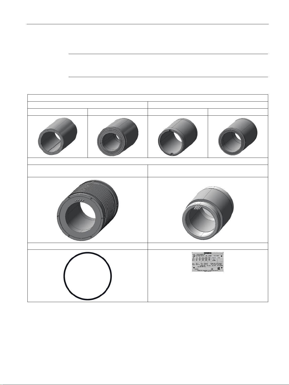
Motor parts
Note
Special versions and construction variants may differ in the scope of delivery with respect to
certain technical aspects.
Rotor
with IPM (internal permanent magnets)
with APM (external permanent magnets)
without sleeve
with sleeve
without sleeve
with sleeve
Stator
quest)
4 O-ring seals
Rating plate
2.4 Technical features and environmental conditions
with cooling jacket without cooling jacket (available only on special motor re-
1FE1 synchronous built-in motors
Hardware Installation Manual, 12/2016, 610.43000.40b
27

Description
2.4.2.1
Weights and moments of inertia
Motor article number
Order code
Rotor
Stator weight
[kg]
Rotor weight
[kg]
Moment of inertia
[kg * m2]
6-pole built-in motors
1FE1041–6W☐☐☐–☐BA☐
-
2.50
0.35
0.00019
1FE1042–6W☐☐☐–☐BA☐
-
4.00
0.60
0.00033
1FE1051–6W☐☐☐–☐BA☐
-
4.00
1.20
0.00106
1FE1051–6W☐☐☐–☐BC☐
-
4.00
1.90
0.00152
1FE1052–6W☐☐☐–☐BA☐
-
6.00
2.20
0.00195
1FE1052–6W☐☐☐–☐BC☐
-
6.00
3.10
0.00248
1FE1054–6W☐☐☐–☐BA☐
-
10.00
4.30
0.00380
1FE1061–6W☐☐☐–☐BA☐
-
4.00
1.10
0.00141
1FE1061–6W☐☐☐–☐BB☐
-
4.00
2.10
0.00242
1FE1062–6W☐☐☐–☐BB☐
6.50
2.20
0.00283
1FE1064–6W☐☐☐–☐BA☐
-
11.50
4.30
0.00553
1FE1082–6W☐☐☐–☐BA☐
-
12.00
3.60
0.01048
1FE1082–6W☐☐☐–☐BB☐
-
12.00
7.70
0.01841
1FE1082–6W☐☐☐–☐BN☐
T34
12.00
7.70
0.01841
1FE1082–6W☐☐☐–☐BC☐
-
12.00
6.80
0.01710
1FE1082–6W☐☐☐–☐BN☐
T37
12.00
6.80
0.01710
1FE1082–6W☐☐☐–☐BD☐
-
12.00
6.10
0.01604
1FE1083–6W☐☐☐–☐BA☐
-
17.00
5.70
0.01659
1FE1083–6W☐☐☐–☐BB☐
-
17.00
10.60
0.02535
1FE1084–6W☐☐☐–☐BA☐
-
22.00
7.10
0.02067
1FE1084–6W☐☐☐–☐BB☐
-
22.00
13.60
0.03959
1FE1084–6W☐☐☐–☐BC☐
-
22.00
12.20
0.03068
1FE1091–6W☐☐☐–☐BA☐
-
14.00
2.60
0.00814
1FE1091–6W☐☐☐–☐BB☐
-
14.00
5.40
0.01423
1FE1091–6W☐☐☐–☐BC☐
-
14.00
4.50
0.01293
1FE1092–6W☐☐☐–☐BA☐
-
21.00
5.00
0.01566
1FE1092–6W☐☐☐–☐BB☐
-
21.00
9.10
0.02398
1FE1092–6W☐☐☐–☐BC☐
-
21.00
7.50
0.02155
1FE1092–6W☐☐☐–☐BN☐1)
T37
21.00
8.30
0.02289
1FE1093–6W☐☐☐–☐BA☐
-
28.00
7.40
0.02317
1FE1093–6W☐☐☐–☐BB☐
-
28.00
12.70
0.03346
1FE1093–6W☐☐☐–☐BC☐
-
28.00
10.50
0.03017
1FE1093–6W☐☐☐–☐BN☐1)
T06
28.00
10.50
0.03017
1FE1113–6W☐☐☐–☐BA☐
-
43.00
9.70
0.04765
1FE1113–6W☐☐☐–☐BD☐
-
43.00
19.80
0.07747
1FE1113–6W☐☐☐–☐BE☐
-
43.00
14.50
0.06512
1FE1114–6W☐☐☐–☐BA☐
-
54.00
12.70
0.06239
1FE1114–6W☐☐☐–☐BB☐
-
54.00
24.90
0.09843
1FE1114–6W☐☐☐–☐BC☐
-
54.00
19.60
0.08650
1FE1114–6W☐☐☐–☐BN☐1)
T46
54.00
22.40
0.09342
1FE1114–6W☐☐☐–☐BN☐1)
T49
54.00
20.80
0.08971
1FE1114–6W☐☐☐–☐BN☐1)
T52
54.00
18.60
0.08353
1FE1114–6W☐☐☐–☐BN☐1)
T55
54.00
17.90
0.08279
1FE1115–6W☐☐☐–☐BC☐
-
65.00
23.80
0.10503
1FE1116–6W☐☐☐–☐BA☐
-
73.00
18.90
0.09285
2.4 Technical features and environmental conditions
Table 2- 2 Weights and moments of inertia
1FE1 synchronous built-in motors
28 Hardware Installation Manual, 12/2016, 610.43000.40b

Description
Motor article number
Order code
Rotor
Stator weight
[kg]
Rotor weight
[kg]
Moment of inertia
[kg * m2]
1FE1116–6W☐☐☐–☐BB☐
-
73.00
35.80
0.14152
1FE1116–6W☐☐☐–☐BC☐
-
73.00
28.20
0.12445
8-pole built-in motors
1FE1143–8W☐☐☐–☐BA☐
68.00
10.40
0.08627
1FE1144–8W☐☐☐–☐BA☐
-
82.00
14.50
0.11447
1FE1144–8W☐☐☐–☐BC☐
-
82.00
24.00
0.18349
1FE1145–8W☐☐☐–☐BC☐
-
96.00
28.30
0.21636
1FE1145–8W☐☐☐–☐BD☐
-
96.00
34.00
0.24759
1FE1145–8W☐☐☐–☐BE☐
-
96.00
41.50
0.28115
1FE1147–8W☐☐☐–☐BC☐
-
124.00
37.70
0.28823
1FE1147–8W☐☐☐–☐BD☐
-
124.00
45.20
0.32915
4-pole built-in motors
1FE1051–4W☐☐☐–☐BA☐
-
4.50
0.70
0.00057
1FE1051–4H☐☐☐–☐BA☐
-
4.50
0.60
0.00045
1FE1052–4W☐☐☐–☐BA☐
-
7.00
1.35
0.00110
1FE1052–4H☐☐☐–☐BA☐
-
7.00
1.15
0.00087
1FE1053–4W☐☐☐–☐BA☐
-
9.50
2.00
0.00163
1FE1053–4H☐☐☐-☐BA☐
-
9.50
1.70
0.00128
1FE1072–4W☐☐☐–☐BA☐
-
12.50
2.20
0.00287
1FE1073–4W☐☐☐–☐BA☐
-
16.00
3.30
0.00430
1FE1074–4W☐☐☐–☐BA☐
-
19.50
4.40
0.00573
1FE1075–4W☐☐☐–☐BA☐
-
23.00
5.50
0.00741
1FE1082–4W☐☐☐–☐BA☐
-
15.00
3.10
0.00559
1FE1083–4W☐☐☐–☐BA☐
-
20.00
4.70
0.00847
1FE1084–4W☐☐☐–☐BA☐
-
25.00
6.20
0.01118
1FE1085–4W☐☐☐–☐BA☐
-
30.00
7.70
0.01388
1FE1092–4W☐☐☐–☐BR☐
-
26.00
3.80
0.00916
1FE1093–4W☐☐☐–☐BA☐
-
33.00
7.50
0.01694
1FE1093–4W☐☐☐–☐BR☐
-
33.00
5.60
0.01350
1FE1094–4W☐☐☐–☐BA☐
-
40.50
9.60
0.02168
1FE1094–4W☐☐☐–☐BR☐
-
40.50
7.50
0.01808
1FE1095–4W☐☐☐–☐BA☐
-
48.00
11.70
0.02642
1FE1095–4W☐☐☐–☐BR☐
-
48.00
9.30
0.02242
1FE1096–4W☐☐☐–☐BA☐
-
55.50
13.90
0.03139
1FE1096–4W☐☐☐–☐BR☐
-
55.50
11.20
0.02700
1FE1103–4W☐☐☐–☐BA☐
-
35.00
5.30
0.01589
1FE1104–4W☐☐☐–☐BA☐
-
43.00
7.00
0.02098
1FE1105–4W☐☐☐–☐BA☐
-
52.00
8.70
0.02608
1FE1106–4W☐☐☐–☐BA☐
-
60.00
10.50
0.03147
1FE1124–4W☐☐☐–☐BA☐
-
58.00
12.10
0.05112
1FE1125–4W☐☐☐–☐BA☐
-
69.50
15.00
0.06337
1FE1126–4W☐☐☐–☐BA☐
-
81.00
18.00
0.07604
1) As an alternative, Z is also valid for N.
Note
Rotor weights
The weights of special version
2.4 Technical features and environmental conditions
1FE1 synchronous built-in motors
Hardware Installation Manual, 12/2016, 610.43000.40b
s are specified on the rating plate.
29
Description
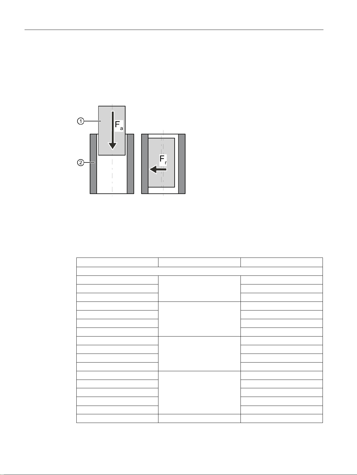
2.4.2.2
Magnetic forces that occur
Table 5-5 Magnetic forces of attraction
Acting magnetic forces of attraction
①
Spindle shaft with rotor core
②
Stator core with spindle housing
Fa
Axial attractive force
Fr
Radial attractive force
Motor type
Axial attractive force Fa [N]
Radial attractive force Fr [N]
Rotors with internal permanent magnets (IPM)
1FE1051-4W
290
1FE1052-4W
580
1FE1053-4W
870
1FE1072-4W
700
1FE1073-4W
1050
1FE1074-4W
1400
1FE1075-4W
1750
1FE1082-4W
850
1FE1083-4W
1275
1FE1084-4W
1700
1FE1085-4W
2125
1FE1092-4W
1000
1FE1093-4W
1500
1FE1094-4W
2000
1FE1096-4W
3000
1FE1051-6W
180
200
2.4 Technical features and environmental conditions
Figure 2-1 Attractive_forces_motor_spindle
1FE1095-4W 2500
189
260
300
180
1FE1 synchronous built-in motors
30 Hardware Installation Manual, 12/2016, 610.43000.40b
 Loading...