

Page 1
Page 2

Page 3
___________________
___________________
___________________
___________________
___________________
___________________
___________________
___________________
___________________
___________________
___________________
___________________
SIMOTICS
Drive technology
1FN3 linear motors
Configuration Manual
10/2018
6SN1197
Introduction
Fundamental safety
instructions
1
Description of the motor
2
Mechanical properties
3
Motor components and
options
4
Configuration
5
Technical data and
characteristics
6
Preparation for use
7
Electrical connection
8
Assembly drawings/
dimension sheets
9
Coupled motors
10
Appendix
A
-0AB86-0BP2
Page 4

Siemens AG
Division Digital Factory
Postfach 48 48
90026 NÜRNBERG
GERMANY
Document order number: 6SN1197-0AB86-0BP2
Ⓟ
Copyright © Siemens AG 2010 - 2018.
All rights reserved
Legal information
Warning notice system
DANGER
indicates that death or severe personal injury will result if proper precautions are not taken.
WARNING
indicates that death or severe personal injury may result if proper precautions are not taken.
CAUTION
indicates that minor personal injury can result if proper precautions are not taken.
NOTICE
indicates that property damage can result if proper precautions are not taken.
Qualified Personnel
personnel qualified
Proper use of Siemens products
WARNING
Siemens products may only be used for the applications described in the catalog and in the relevant technical
ambient conditions must be complied with. The information in the relevant documentation must be observed.
Trademarks
Disclaimer of Liability
This manual contains notices you have to observe in order to ensure your personal safety, as well as to prevent
damage to property. The notices referring to your personal safety are highlighted in the manual by a safety alert
symbol, notices referring only to property damage have no safety alert symbol. These notices shown below are
graded according to the degree of danger.
If more than one degree of danger is present, the warning notice representing the highest degree of danger will
be used. A notice warning of injury to persons with a safety alert symbol may also include a warning relating to
property damage.
The product/system described in this documentation may be operated only by
task in accordance with the relevant documentation, in particular its warning notices and safety instructions.
Qualified personnel are those who, based on their training and experience, are capable of identifying risks and
avoiding potential hazards when working with these products/systems.
Note the following:
documentation. If products and components from other manufacturers are used, these must be recommended
or approved by Siemens. Proper transport, storage, installation, assembly, commissioning, operation and
maintenance are required to ensure that the products operate safely and without any problems. The permissible
All names identified by ® are registered trademarks of Siemens AG. The remaining trademarks in this publication
may be trademarks whose use by third parties for their own purposes could violate the rights of the owner.
We have reviewed the contents of this publication to ensure consistency with the hardware and software
described. Since variance cannot be precluded entirely, we cannot guarantee full consistency. However, the
information in this publication is reviewed regularly and any necessary corrections are included in subsequent
editions.
for the specific
10/2018 Subject to change
Page 5

Introduction
Standard version
Target group
Benefits
Text features
Operating instructions
This documentation only describes the functionality of the standard version. The machine
OEM documents any extensions or changes to the motor made by it.
For reasons of clarity, this documentation cannot contain all of the detailed information on all
of the product types. Moreover, this documentation cannot take into consideration every
possible type of installation, operation, and maintenance.
This documentation should be kept in a location where it can be easily accessed and made
available to the personnel responsible.
This manual is aimed at planning, project, and design engineers as well as electricians,
fitters, and service personnel.
This manual provides information on the rules and guidelines that must be observed when
configuring a system with motors from the 1FN3 product family. It also helps with the
selection of peak and continuous load motors within this range.
In addition to the notes that you must observe for your own personal safety as well as to
avoid material damage, in this document you will find the following text features:
Operating instructions with the specified sequence are designated using the following
symbols:
The arrow indicates the start of the operating instructions.
The individual handling steps are numbered.
1. Execute the operating instructions in the specified sequence.
The square indicates the end of the operating instruction.
Operating instructions without a specified sequence are identified using a bullet point:
● Execute the operating instructions.
1FN3 linear motors
Configuration Manual, 10/2018, 6SN1197-0AB86-0BP2
3
Page 6

Introduction
Enumerations
Notes
Note
A Note is an important item of information about the product, handling of the product or the
relevant section of the document. Notes provide you with help or further suggestions/ideas.
More information
Internet address for products
My support
Note
If you want to use this function, you must first register.
Later, you can log on with your login data.
● Enumerations are identified by a bullet point without any additional symbols.
– Enumerations at the second level are hyphenated.
Notes are shown as follows:
Information on the following topics is available at:
● Ordering documentation / overview of documentation
● Additional links to download documents
● Using documentation online (find and search in manuals / information)
More information (https://support.industry.siemens.com/cs/de/en/view/108998034)
If you have any questions regarding the technical documentation (e.g. suggestions,
corrections), please send an e-mail to the following address E-mail
(mailto:docu.motioncontrol@siemens.com).
Products (http://www.siemens.com/motioncontrol)
The following link provides information on how to create your own individual documentation
based on Siemens content, and adapt it for your own machine documentation:
My support (https://support.industry.siemens.com/My/de/en/documentation)
1FN3 linear motors
4 Configuration Manual, 10/2018, 6SN1197-0AB86-0BP2
Page 7

Introduction
Training
Technical Support
Usage phases and their documents/tools
Usage phase
Document / tool / measure
The following link provides information on SITRAIN – training from Siemens for products,
systems and automation engineering solutions:
SITRAIN (http://siemens.com/sitrain)
Country-specific telephone numbers for technical support are provided on the Internet under
Contact:
Technical Support (https://support.industry.siemens.com)
Table 1 Usage phases and the required documents/tools
Orientation
Planning / configuring
Deciding / ordering
Transporting / storing
• SINAMICS S Sales Documentation
• Siemens Internet pages Motion Control
• SIZER configuration tool
• CAD-Creator selection and engineering tool
for dimension drawings, 2D/3D CAD data, generating system documentation
• DT Configurator to select and configure drive products
• Configuration Manuals, Motors
• Configuring notes from Catalog NC 62
• SINAMICS S120 Configuration Manuals
• SINAMICS S120 Safety Integrated Function Manual
• SINAMICS S120 List Manual
• Technical Support
– Mechatronic support
– Application support
– Technical Application Center
• Catalogs NC 62, PM 21
• SIZER configuring tool (generating parts lists)
• Operating instructions, motors
1FN3 linear motors
Configuration Manual, 10/2018, 6SN1197-0AB86-0BP2
5
Page 8

Introduction
Usage phase
Document / tool / measure
disposal
Websites of third parties
Installation / mounting
Commissioning /
operating
Maintenance /
decommissioning /
• Operating instructions, motors
• Installation instructions for the machine
• SINAMICS S120 Equipment Manuals
• Documentation for encoders
• Examples of additional, possibly necessary documentation for the
following system components:
– Cooling system
– Brake
– Line filter
– HFD reactor or Active Interface Module
• Siemens commissioning training courses (SITRAIN courses)
• Commissioning support provided by Siemens
• Operating instructions, motors
• Configuration Manual Motors
• STARTER commissioning tool
• SINAMICS S120 Getting Started
• SINAMICS S120 Manuals
• SINAMICS S120 Commissioning Manual
• SINAMICS S120 List Manual
• SINAMICS S120 Function Manuals
• Documentation for encoders
• Examples of additional, possibly necessary documentation for the
following system components:
– Cooling system
– Brake
– Line filter
– HFD reactor or Active Interface Module
• Operating instructions, motors
This publication contains hyperlinks to websites of third parties. Siemens does not take any
responsibility for the contents of these websites or adopt any of these websites or their
contents as their own, because Siemens does not control the information on these websites
and is also not responsible for the contents and information provided there. Use of these
websites is at the risk of the person doing so.
1FN3 linear motors
6 Configuration Manual, 10/2018, 6SN1197-0AB86-0BP2
Page 9

Introduction
Information regarding third-party products
Note
Recommendation relating to third-party products
This document contains recommendations relating to third
the fundamental suitability of these third
You can use equivalent products from other manufacturers.
Siemens does not accept any warranty for the pro
-party products. Siemens accepts
-party products.
perties of third-party products.
1FN3 linear motors
Configuration Manual, 10/2018, 6SN1197-0AB86-0BP2
7
Page 10

Introduction
1FN3 linear motors
8 Configuration Manual, 10/2018, 6SN1197-0AB86-0BP2
Page 11

Table of contents
Introduction ............................................................................................................................................. 3
1 Fundamental safety instructions ............................................................................................................ 13
2 Description of the motor ........................................................................................................................ 23
3 Mechanical properties ........................................................................................................................... 59
1.1 General safety instructions ..................................................................................................... 13
1.2 Equipment damage due to electric fields or electrostatic discharge ...................................... 18
1.3 Industrial security .................................................................................................................... 19
1.4 Residual risks of power drive systems .................................................................................... 21
2.1 Highlights and benefits............................................................................................................ 23
2.1.1 Overview ................................................................................................................................. 23
2.1.2 Benefits ................................................................................................................................... 24
2.2 Use for the intended purpose ................................................................................................. 26
2.3 Technical features and environmental conditions .................................................................. 27
2.3.1 Directives and standards ........................................................................................................ 27
2.3.2 Danger from strong magnetic fields ........................................................................................ 29
2.3.3 Technical features ................................................................................................................... 34
2.3.4 Direction of motion of the motor .............................................................................................. 35
2.3.5 Ambient conditions for stationary use ..................................................................................... 36
2.3.6 Scope of delivery .................................................................................................................... 37
2.3.6.1 Scope of delivery linear motor ................................................................................................ 37
2.3.6.2 Supplied pictograms ............................................................................................................... 38
2.4 Derating factors ....................................................................................................................... 40
2.5 Selection and ordering data .................................................................................................... 40
2.5.1 Order designation ................................................................................................................... 40
2.5.1.1 Primary sections ..................................................................................................................... 41
2.5.1.2 Secondary sections ................................................................................................................. 41
2.5.1.3 Primary section accessories ................................................................................................... 42
2.5.1.4 Accessories for the secondary section track .......................................................................... 44
2.5.1.5 Ordering examples .................................................................................................................. 47
2.5.2 Selection and ordering data 1FN3 .......................................................................................... 50
2.6 Rating plate data ..................................................................................................................... 57
3.1 Cooling .................................................................................................................................... 59
3.1.1 Design of the cooling .............................................................................................................. 59
3.1.2 Cooling circuits ........................................................................................................................ 65
3.1.3 Coolants .................................................................................................................................. 70
3.2 Degree of protection ............................................................................................................... 71
3.3 Vibration response .................................................................................................................. 72
3.4 Noise emission ........................................................................................................................ 72
1FN3 linear motors
Configuration Manual, 10/2018, 6SN1197-0AB86-0BP2
9
Page 12

Table of contents
4 Motor components and options ............................................................................................................. 83
5 Configuration ....................................................................................................................................... 103
3.5 Service and inspection intervals ............................................................................................ 73
3.5.1 Safety instructions for maintenance ....................................................................................... 73
3.5.2 Maintenance ........................................................................................................................... 78
3.5.3 Checking the insulation resistance ........................................................................................ 80
3.5.4 The inspection and change intervals for the coolant ............................................................. 81
4.1 Motor components ................................................................................................................. 83
4.1.1 Overview of the motor construction ....................................................................................... 83
4.1.2 Temperature monitoring and thermal motor protection ......................................................... 85
4.1.2.1 Temperature monitoring circuits Temp-S and Temp-F .......................................................... 85
4.1.2.2 Technical features of temperature sensors ........................................................................... 88
4.1.3 Encoders ................................................................................................................................ 91
4.1.4 Hall Sensor Box ..................................................................................................................... 95
4.1.5 Braking concepts.................................................................................................................... 97
4.2 Options ................................................................................................................................... 99
5.1 Configuring software ............................................................................................................ 103
5.1.1 SIZER configuration tool ...................................................................................................... 103
5.1.2 STARTER drive/commissioning software ............................................................................ 104
5.2 Configuring workflow ............................................................................................................ 104
5.2.1 Mechanical boundary conditions.......................................................................................... 106
5.2.2 Type of duty cycle ................................................................................................................ 109
5.2.3 Calculating forces................................................................................................................. 113
5.2.4 Selection of the primary sections ......................................................................................... 114
5.2.5 Specifying the number of secondary sections ..................................................................... 116
5.2.6 Operation in the area of reduced magnetic coverage.......................................................... 118
5.2.7 Checking the dynamic mass ................................................................................................ 119
5.2.8 Selecting the power module ................................................................................................. 119
5.2.9 Calculation of the required infeed ........................................................................................ 120
5.3 Examples ............................................................................................................................. 121
5.3.1 Positioning in a specified time .............................................................................................. 121
5.3.2 Gantry with transverse axis .................................................................................................. 130
5.3.3 Dimensioning the cooling system ........................................................................................ 132
5.3.3.1 Basic information.................................................................................................................. 132
5.3.3.2 Example: Dimensioning the cooling ..................................................................................... 133
5.4 Mounting .............................................................................................................................. 136
5.4.1 Safety instructions for mounting........................................................................................... 136
5.4.2 Mechanical design ............................................................................................................... 139
5.4.3 Specifications for mounting linear motors ............................................................................ 140
5.4.4 Procedure when installing the motor ................................................................................... 142
5.4.4.1 Comply with the installation dimensions .............................................................................. 143
5.4.4.2 Motor installation procedures ............................................................................................... 144
5.4.5 Assembling individual motor components ........................................................................... 150
5.4.6 Cooler connection ................................................................................................................ 158
5.4.6.1 Primary section cooling connection ..................................................................................... 158
5.4.6.2 Secondary section cooling connection ................................................................................ 160
1FN3 linear motors
10 Configuration Manual, 10/2018, 6SN1197-0AB86-0BP2
Page 13

Table of contents
6 Technical data and characteristics ...................................................................................................... 165
7 Preparation for use ............................................................................................................................. 473
8 Electrical connection ........................................................................................................................... 483
9 Assembly drawings/dimension sheets ................................................................................................. 509
5.4.7 Checking the work carried out .............................................................................................. 162
5.4.7.1 Smooth running of the slide .................................................................................................. 162
5.4.7.2 Check of the air gap height ................................................................................................... 163
6.1 Explanations ......................................................................................................................... 166
6.1.1 Explanations of the formula abbreviations ............................................................................ 166
6.1.2 Explanations of the characteristic curves ............................................................................. 170
6.2 Data sheets and characteristics ............................................................................................ 174
6.2.1 1FN3050-xxxxx-xxxx ............................................................................................................. 174
6.2.2 1FN3100-xxxxx-xxxx ............................................................................................................. 186
6.2.3 1FN3150-xxxxx-xxxx ............................................................................................................. 228
6.2.4 1FN3300-xxxxx-xxxx ............................................................................................................. 261
6.2.5 1FN3450-xxxxx-xxxx ............................................................................................................. 303
6.2.6 1FN3600-xxxxx-xxxx ............................................................................................................. 372
6.2.7 1FN3900-xxxxx-xxxx ............................................................................................................. 432
6.2.8 Additional characteristic curves ............................................................................................ 471
7.1 Transporting .......................................................................................................................... 474
7.1.1 Ambient conditions for transportation ................................................................................... 474
7.1.2 Packaging specifications for air transportation ..................................................................... 475
7.1.3 Lifting primary sections ......................................................................................................... 478
7.2 Storage ................................................................................................................................. 479
7.2.1 Ambient conditions for long-term storage ............................................................................. 479
7.2.2 Storage in rooms and protection against humidity ............................................................... 480
8.1 Permissible line system types ............................................................................................... 485
8.2 Motor circuit diagram ............................................................................................................ 486
8.3 System integration ................................................................................................................ 486
8.3.1 Drive system ......................................................................................................................... 486
8.3.2 Sensor Module SME12x ....................................................................................................... 490
8.3.3 TM120 Terminal Module ....................................................................................................... 490
8.3.4 SMC20 Sensor Module ......................................................................................................... 490
8.3.5 Pin assignments and connection types ................................................................................ 490
8.3.6 Terminal panel ...................................................................................................................... 493
8.3.7 Power connection ................................................................................................................. 498
8.3.8 Signal connection .................................................................................................................. 500
8.3.9 Shielding, grounding, and equipotential bonding .................................................................. 506
8.3.10 Requirements for the motor supply cables ........................................................................... 507
9.1 Position tolerance for mounting holes................................................................................... 510
9.2 Installation dimensions.......................................................................................................... 511
9.3 1FN3050, 1FN3100, 1FN3150 ............................................................................................. 512
9.3.1 1FN3050 ............................................................................................................................... 512
9.3.2 1FN3100, 1FN3150 .............................................................................................................. 519
9.3.3 Mounting the Hall sensor box ............................................................................................... 527
1FN3 linear motors
Configuration Manual, 10/2018, 6SN1197-0AB86-0BP2
11
Page 14

Table of contents
10 Coupled motors ................................................................................................................................... 569
A Appendix ............................................................................................................................................. 585
Glossary .............................................................................................................................................. 593
Index ................................................................................................................................................... 595
9.3.4 Heatsink profiles................................................................................................................... 531
9.4 1FN3300, 1FN3450 ............................................................................................................. 533
9.4.1 Mounting the Hall sensor box .............................................................................................. 543
9.4.2 Heatsink profiles................................................................................................................... 547
9.5 1FN3600 .............................................................................................................................. 549
9.5.1 Mounting the Hall sensor box .............................................................................................. 554
9.5.2 Heatsink profiles................................................................................................................... 558
9.6 1FN3900 .............................................................................................................................. 559
9.6.1 Mounting the Hall sensor box .............................................................................................. 564
9.6.2 Heatsink profiles................................................................................................................... 568
10.1 Operating motors connected to an axis in parallel ............................................................... 569
10.2 Master and stoker ................................................................................................................ 570
10.2.1 Tandem arrangement .......................................................................................................... 572
10.2.2 Janus arrangement .............................................................................................................. 573
10.2.3 Parallel arrangement ............................................................................................................ 576
10.2.4 Anti-parallel arrangement ..................................................................................................... 578
10.2.5 Double-sided arrangement .................................................................................................. 580
10.3 Connection examples for parallel operation ........................................................................ 582
A.1 Recommended manufacturers ............................................................................................. 585
A.1.1 Manufacturers of braking elements...................................................................................... 585
A.1.2 Manufacturers of cold water units ........................................................................................ 586
A.1.3 Manufacturers of anti-corrosion agents ............................................................................... 586
A.1.4 Manufacturers of connectors for cooling .............................................................................. 586
A.1.5 Manufacturers of plastic hose manufacturers ...................................................................... 587
A.1.6 Manufacturers of connector nipples and reinforcing sleeves .............................................. 587
A.1.7 Manufacturers of spacer foils ............................................................................................... 587
A.2 List of abbreviations ............................................................................................................. 588
A.3 Environmental compatibility ................................................................................................. 589
A.3.1 Environmental compatibility during production .................................................................... 589
A.3.2 Disposal ............................................................................................................................... 589
A.3.2.1 Guidelines for disposal ......................................................................................................... 590
A.3.2.2 Disposing of secondary sections ......................................................................................... 590
A.3.2.3 Disposal of packaging .......................................................................................................... 591
A.4 Terminal markings according to EN 60034-8:2002 ............................................................. 591
1FN3 linear motors
12 Configuration Manual, 10/2018, 6SN1197-0AB86-0BP2
Page 15
1
1.1
General safety instructions
WARNING
Electric shock and danger to life due to other energy sources
WARNING
Electric shock due to connection to an unsuitable power supply
Touching live components can result in death or severe injury.
• Only work on electrical devices when you are qualified for this job.
• Always observe the country-specific safety rules.
Generally, the following six steps apply when establishing safety:
1. Prepare for disconnection. Notify all those who will be affected by the procedure.
2. Isolate the drive system from the power supply and take measures to prevent it being
switched back on again.
3. Wait until the discharge time specified on the warning labels has elapsed.
4. Check that there is no voltage between any of the power connections, and between any
of the power connections and the protective conductor connection.
5. Check whether the existing auxiliary supply circuits are de-energized.
6. Ensure that the motors cannot move.
7. Identify all other dangerous energy sources, e.g. compressed air, hydraulic systems, or
water. Switch the energy sources to a safe state.
8. Check that the correct drive system is completely locked.
After you have completed the work, restore the operational readiness in the inverse
sequence.
When equipment is connected to an unsuitable power supply, exposed components may
carry a hazardous voltage that might result in serious injury or death.
• Only use power supplies that provide SELV (Safety Extra Low Voltage) or PELV
(Protective Extra Low Voltage) output voltages for all connections and terminals of the
electronics modules.
1FN3 linear motors
Configuration Manual, 10/2018, 6SN1197-0AB86-0BP2
13
Page 16
Fundamental safety instructions
WARNING
Electric shock due to damaged motors or devices
WARNING
Electric shock due to unconnected cable shield
WARNING
Electric shock if there is no ground connection
WARNING
Arcing when a plug connection is opened during operation
1.1 General safety instructions
Improper handling of motors or devices can damage them.
Hazardous voltages can be present at the enclosure or at exposed components on
damaged motors or devices.
• Ensure compliance with the limit values specified in the technical data during transport,
storage and operation.
• Do not use any damaged motors or devices.
Hazardous touch voltages can occur through capacitive cross-coupling due to unconnected
cable shields.
• As a minimum, connect cable shields and the conductors of power cables that are not
used (e.g. brake cores) at one end at the grounded housing potential.
For missing or incorrectly implemented protective conductor connection for devices with
protection class I, high voltages can be present at open, exposed parts, which when
touched, can result in death or severe injury.
• Ground the device in compliance with the applicable regulations.
Opening a plug connection when a system is operation can result in arcing that may cause
serious injury or death.
• Only open plug connections when the equipment is in a voltage-free state, unless it has
been explicitly stated that they can be opened in operation.
1FN3 linear motors
14 Configuration Manual, 10/2018, 6SN1197-0AB86-0BP2
Page 17
Fundamental safety instructions
NOTICE
Property damage due to loose power connections
WARNING
Unexpected movement of machines caused by radio devices or mobile phones
WARNING
Unrecognized dangers due to missing or illegible warning labels
1.1 General safety instructions
Insufficient tightening torques or vibration can result in loose power connections. This can
result in damage due to fire, device defects or malfunctions.
• Tighten all power connections to the prescribed torque.
• Check all power connections at regular intervals, particularly after equipment has been
transported.
When radio devices or mobile phones with a transmission power > 1 W are used in the
immediate vicinity of components, they may cause the equipment to malfunction.
Malfunctions may impair the functional safety of machines and can therefore put people in
danger or lead to property damage.
• If you come closer than around 2 m to such components, switch off any radios or mobile
phones.
• Use the "SIEMENS Industry Online Support app" only on equipment that has already
been switched off.
Dangers might not be recognized if warning labels are missing or illegible. Unrecognized
dangers may cause accidents resulting in serious injury or death.
• Check that the warning labels are complete based on the documentation.
• Attach any missing warning labels to the components, where necessary in the national
language.
• Replace illegible warning labels.
1FN3 linear motors
Configuration Manual, 10/2018, 6SN1197-0AB86-0BP2
15
Page 18
Fundamental safety instructions
WARNING
Unexpected movement of machines caused by inactive safety functions
Note
Important safety notices for Safety Integrated functions
If you want to use Safety Integrated functions, you must observe the safety notices in the
Safety Integrated manuals.
WARNING
Active implant malfunctions due to electromagnetic fields
1.1 General safety instructions
Inactive or non-adapted safety functions can trigger unexpected machine movements that
may result in serious injury or death.
• Observe the information in the appropriate product documentation before
commissioning.
• Carry out a safety inspection for functions relevant to safety on the entire system,
including all safety-related components.
• Ensure that the safety functions used in your drives and automation tasks are adjusted
and activated through appropriate parameterizing.
• Perform a function test.
• Only put your plant into live operation once you have guaranteed that the functions
relevant to safety are running correctly.
Electromagnetic fields (EMF) are generated by the operation of electrical power equipment,
such as transformers, converters, or motors. People with pacemakers or implants are at
particular risk in the immediate vicinity of this equipment.
• If you have a heart pacemaker or implant, maintain the minimum distance specified in
chapter "Correct usage" from such motors.
1FN3 linear motors
16 Configuration Manual, 10/2018, 6SN1197-0AB86-0BP2
Page 19
Fundamental safety instructions
WARNING
Active implant malfunctions due to permanent-magnet fields
WARNING
Injury caused by moving or ejected parts
WARNING
Fire due to inadequate cooling
WARNING
Fire due to incorrect operation of the motor
1.1 General safety instructions
Even when switched off, electric motors with permanent magnets represent a potential risk
for persons with heart pacemakers or implants if they are close to converters/motors.
• If you have a heart pacemaker or implant, maintain the minimum distance specified in
chapter "Correct usage".
• When transporting or storing permanent-magnet motors always use the original packing
materials with the warning labels attached.
• Clearly mark the storage locations with the appropriate warning labels.
• IATA regulations must be observed when transported by air.
Contact with moving motor parts or drive output elements and the ejection of loose motor
parts (e.g. feather keys) out of the motor enclosure can result in severe injury or death.
• Remove any loose parts or secure them so that they cannot be flung out.
• Do not touch any moving parts.
• Safeguard all moving parts using the appropriate safety guards.
Inadequate cooling can cause the motor to overheat, resulting in death or severe injury as a
result of smoke and fire. This can also result in increased failures and reduced service lives
of motors.
• Comply with the specified cooling requirements for the motor.
When incorrectly operated and in the case of a fault, the motor can overheat resulting in fire
and smoke. This can result in severe injury or death. Further, excessively high temperatures destroy motor components and result in increased failures as well as shorter service
lives of motors.
• Operate the motor according to the relevant specifications.
• Only operate the motors in conjunction with effective temperature monitoring.
• Immediately switch off the motor if excessively high temperatures occur.
1FN3 linear motors
Configuration Manual, 10/2018, 6SN1197-0AB86-0BP2
17
Page 20
Fundamental safety instructions
CAUTION
Burn injuries caused by hot surfaces
1.2
Equipment damage due to electric fields or electrostatic discharge
NOTICE
Equipment damage due to electric fields or electrostatic discharge
1.2 Equipment damage due to electric fields or electrostatic discharge
In operation, the motor can reach high temperatures, which can cause burns if touched.
• Mount the motor so that it is not accessible in operation.
Measures when maintenance is required:
• Allow the motor to cool down before starting any work.
• Use the appropriate personnel protection equipment, e.g. gloves.
Electrostatic sensitive devices (ESD) are individual components, integrated circuits, modules
or devices that may be damaged by either electric fields or electrostatic discharge.
Electric fields or electrostatic discharge can cause malfunctions through damaged
individual components, integrated circuits, modules or devices.
• Only pack, store, transport and send electronic components, modules or devices in their
original packaging or in other suitable materials, e.g conductive foam rubber of
aluminum foil.
• Only touch components, modules and devices when you are grounded by one of the
following methods:
– Wearing an ESD wrist strap
– Wearing ESD shoes or ESD grounding straps in ESD areas with conductive flooring
• Only place electronic components, modules or devices on conductive surfaces (table
with ESD surface, conductive ESD foam, ESD packaging, ESD transport container).
1FN3 linear motors
18 Configuration Manual, 10/2018, 6SN1197-0AB86-0BP2
Page 21

Fundamental safety instructions
1.3
Industrial security
Note
Industrial security
Siemens provides products and solutions with industrial security functions that support the
secure operation of plants, systems, machines and networks.
In order to protect plants, systems, machines and networks against cyber threats, it
necessary to implement
security concept. Siemens
Customers are responsible for preventing unauthorized access to the
machines and networks. Such systems, machines and components should only be
connected to an enterprise network or the Internet if and to the extent such a connection is
necessary and only when appropriate security measures (e.g. firewal
segmentation) are in place.
For additional information on industrial security measures that may be implemented, please
visit:
Industrial security (
Siemens
secure. Siemens strongly recommends that product updates are applied as soon as they are
available and that the latest product versions are used. Use of product v
longer supported, and failure to apply the latest updates may increase customer
to cyber threats.
To stay informed about product updates, subscribe to the Siemens Industrial Security RSS
Feed at:
Industrial security (
1.3 Industrial security
is
– and continuously maintain – a holistic, state-of-the-art industrial
’ products and solutions constitute one element of such a concept.
ir plants, systems,
ls and/or network
http://www.siemens.com/industrialsecurity)
’ products and solutions undergo continuous development to make them more
http://www.siemens.com/industrialsecurity)
Further information is provided on the Internet:
Industrial Security Configuration Manual
(https://support.industry.siemens.com/cs/ww/en/view/108862708)
ersions that are no
’s exposure
1FN3 linear motors
Configuration Manual, 10/2018, 6SN1197-0AB86-0BP2
19
Page 22
Fundamental safety instructions
WARNING
Unsafe operating states resulting from software manipulation
1.3 Industrial security
Software manipulations (e.g. viruses, trojans, malware or worms) can cause unsafe
operating states in your system that may lead to death, serious injury, and property
damage.
• Keep the software up to date.
• Incorporate the automation and drive components into a holistic, state-of-the-art
industrial security concept for the installation or machine.
• Make sure that you include all installed products into the holistic industrial security
concept.
• Protect files stored on exchangeable storage media from malicious software by with
suitable protection measures, e.g. virus scanners.
• Protect the drive against unauthorized changes by activating the "know-how protection"
drive function.
1FN3 linear motors
20 Configuration Manual, 10/2018, 6SN1197-0AB86-0BP2
Page 23

Fundamental safety instructions
1.4
Residual risks of power drive systems
1.4 Residual risks of power drive systems
When assessing the machine- or system-related risk in accordance with the respective local
regulations (e.g., EC Machinery Directive), the machine manufacturer or system installer
must take into account the following residual risks emanating from the control and drive
components of a drive system:
1. Unintentional movements of driven machine or system components during
commissioning, operation, maintenance, and repairs caused by, for example,
– Hardware and/or software errors in the sensors, control system, actuators, and cables
and connections
– Response times of the control system and of the drive
– Operation and/or environmental conditions outside the specification
– Condensation/conductive contamination
– Parameterization, programming, cabling, and installation errors
– Use of wireless devices/mobile phones in the immediate vicinity of electronic
components
– External influences/damage
– X-ray, ionizing radiation and cosmic radiation
2. Unusually high temperatures, including open flames, as well as emissions of light, noise,
particles, gases, etc., can occur inside and outside the components under fault conditions
caused by, for example:
– Component failure
– Software errors
– Operation and/or environmental conditions outside the specification
– External influences/damage
3. Hazardous shock voltages caused by, for example:
– Component failure
– Influence during electrostatic charging
– Induction of voltages in moving motors
– Operation and/or environmental conditions outside the specification
– Condensation/conductive contamination
– External influences/damage
4. Electrical, magnetic and electromagnetic fields generated in operation that can pose a
risk to people with a pacemaker, implants or metal replacement joints, etc., if they are too
close
1FN3 linear motors
Configuration Manual, 10/2018, 6SN1197-0AB86-0BP2
21
Page 24

Fundamental safety instructions
1.4 Residual risks of power drive systems
5. Release of environmental pollutants or emissions as a result of improper operation of the
system and/or failure to dispose of components safely and correctly
6. Influence of network-connected communication systems, e.g. ripple-control transmitters
or data communication via the network
For more information about the residual risks of the drive system components, see the
relevant sections in the technical user documentation.
1FN3 linear motors
22 Configuration Manual, 10/2018, 6SN1197-0AB86-0BP2
Page 25
2
2.1
Highlights and benefits
2.1.1
Overview
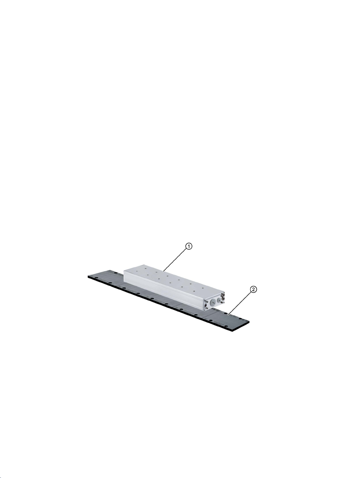
Basic characteristics of the motor
①
Primary section
②
Secondary section
1FN3 motors are permanent-magnet synchronous linear motors with a modular cooling
concept. Depending on the accuracy requirements, the motor can be optionally operated
with a primary section precision cooler and/or a secondary section cooling. To a large extent,
the motors are then thermally neutral with respect to the machine itself.
The motor is delivered in components (at least primary section and secondary sections) and
installed directly in the machine. Due to the series connection of primary and secondary
sections, user-defined motor forces and straight traversing distances of various lengths can
be achieved.
1FN3 linear motors
Configuration Manual, 10/2018, 6SN1197-0AB86-0BP2
The motors are designed for the SINAMICS S120 drive system.
You can use Motor Modules in the "blocksize", "booksize" or "chassis" formats.
23
Page 26
Description of the motor
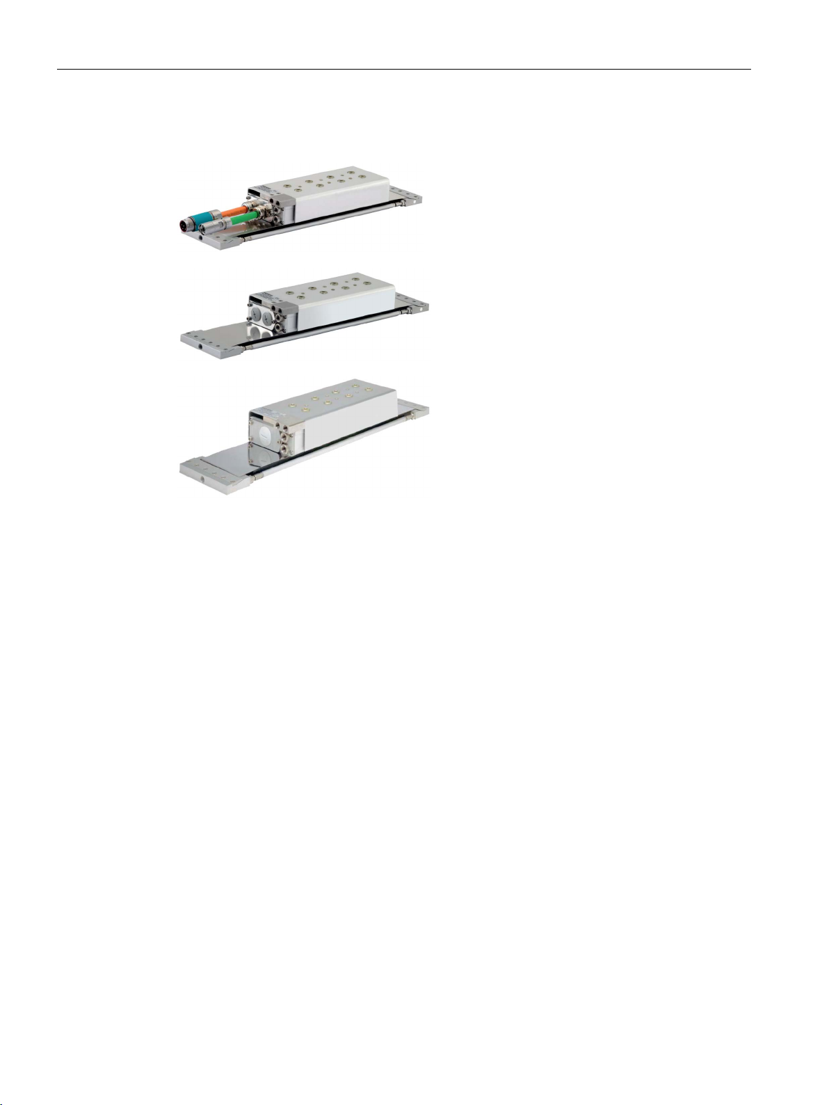
Overview of the connection variants
Peak and continuous load motor
with two pre
with/without connector
Peak and continuous load motor
with connection cover for two cables
Peak load motor
with connector cover for one cable
or
with a fixed cable without a connector
2.1.2
Benefits
2.1 Highlights and benefits
-assembled cables
The general-purpose motors in the 1FN3 product family are powerful linear motors with a
broad range of types. These motors have the following properties:
● High power density
● High dynamic response
● High forces
● Compact design
● Low sensitivity to corrosive ambient conditions
While the peak load motors have high overload capability, the continuous load motors have
a rated force with high availability.
The motors of the 1FN3 product family can be operated in parallel. You will find information
on this in Chapter "Coupled motors (Page 569)".
1FN3 linear motors
24 Configuration Manual, 10/2018, 6SN1197-0AB86-0BP2
Page 27

Description of the motor
Special features
Additional feature on the peak load motor
Additional features on the continuous load motor
2.1 Highlights and benefits
● Modular design: The motor can therefore be configured to optimally match the technical
requirements. The modularity of the motor is explained in Chapter "Motor components
and options (Page 83)".
● The motor is thermally decoupled from the machine using a primary section precision
cooler and secondary section cooling, based on the Thermo-Sandwich
● Simple coolant connection.
● The secondary section track can be fully covered: This provides a smooth surface and
prevents unwanted particle deposits, especially in the gaps between the secondary
sections.
● Simple electrical connection via an integrated terminal panel or permanent cable
connections.
● Low mass and high overload capability: The motor is ideally suited for acceleration drive
applications.
● Low mass and high continuous load capability. The motor is ideally suited to load cycles
with continuous acceleration and braking phases and continuous loads, such as weight
force or process forces.
● Low force ripple. The motor is suitable for high-precision applications.
®
principle.
1FN3 linear motors
Configuration Manual, 10/2018, 6SN1197-0AB86-0BP2
25
Page 28
Description of the motor
2.2
Use for the intended purpose
WARNING
Risk of death and material damage as a result of incorrect use
WARNING
Danger to life for wearers of active implants due to magnetic and electrical fields
Applications for peak load motors
2.2 Use for the intended purpose
There is a risk of death, serious injury and/or material damage when direct drives or their
components are used for a purpose for which they were not intended.
• Only use the motors for industrial or commercial plants and systems.
• Do not install the motors in hazardous zones if the motors have not been expressly and
explicitly designed and authorized for this purpose. Carefully observe any special
additional notes provided.
• Only use direct drives and their components for applications that Siemens has explicitly
specified.
• Protect the motors against dirt and contact with corrosive substances.
• Ensure that the installation conditions comply with the rating plate specifications and the
condition specifications contained in this documentation. Where relevant, take into
account deviations regarding approvals or country-specific regulations.
• Contact your local Siemens office if you have any questions relating to correct use.
• If you wish to use special versions and design versions whose technical details vary
from the motors described in this document, then you must contact your local Siemens
office.
Electric motors pose a danger to people with active medical implants, e.g. cardiac
stimulators, who come close to the motors.
• If you are affected, stay at a minimum distance of 500 mm from the motors (tripping
threshold for static magnetic fields of 0.5 mT according to the Directive 2013/35/EU).
Combined with a drive system with closed-loop control, peak load motors are well suited as
direct drives for linear motion, e.g. for:
● Highly dynamic and flexible machine tools
● Laser machining
● Handling
1FN3 linear motors
26 Configuration Manual, 10/2018, 6SN1197-0AB86-0BP2
Page 29
Description of the motor
Applications for continuous load motors
WARNING
Personal injury and material damage by noncompliance with directive 2006/42/EC
2.3
Technical features and environmental conditions
2.3.1
Directives and standards
Standards that are complied with
2.3 Technical features and environmental conditions
Combined with a drive system with closed-loop control, continuous load motors are well
suited as direct drives for linear motion, e.g. for:
● Oscillating motion (e.g. out-of-center machining)
● Applications with high process forces (e.g. grinding, turning, etc.)
● Vertical axes without weight compensation, quills
● Handling, Cartesian robots
You can use Motor Modules in the "blocksize", "booksize" or "chassis" formats.
There is a risk of death, serious injury and/or material damage if Directive 2006/42/EC is
not carefully observed.
• The products included in the scope of delivery are exclusively designed for installation in
a machine. Commissioning is prohibited until it has been fully established that the end
product conforms with Directive 2006/42/EC.
• Please take into account all safety instructions and provide these to end users.
Please take note of national and international license terms when operating direct motors so
that no patent rights are violated.
The motors of the type series SIMOTICS S, SIMOTICS M, SIMOTICS L, SIMOTICS T,
SIMOTICS A, called "SIMOTICS motor series" below, fulfill the requirements of the following
directives and standards:
● EN 60034-1 – Rotating electrical machines – Dimensioning and operating behavior
● EN 60204-1 – Safety of machinery – Electrical equipment of machines; general
requirements
1FN3 linear motors
Configuration Manual, 10/2018, 6SN1197-0AB86-0BP2
27
Page 30
Description of the motor
Feature
Standard
Degree of protection
IEC / EN 60034-5
Type of construction
IEC / EN 60034-7
Noise levels 1)
IEC / EN 60034-9
Temperature monitoring
IEC / EN 60034-11
Vibration severity grades 1)
IEC / EN 60034-14
1)
Standard component, e.g. cannot be applied to built-in motors
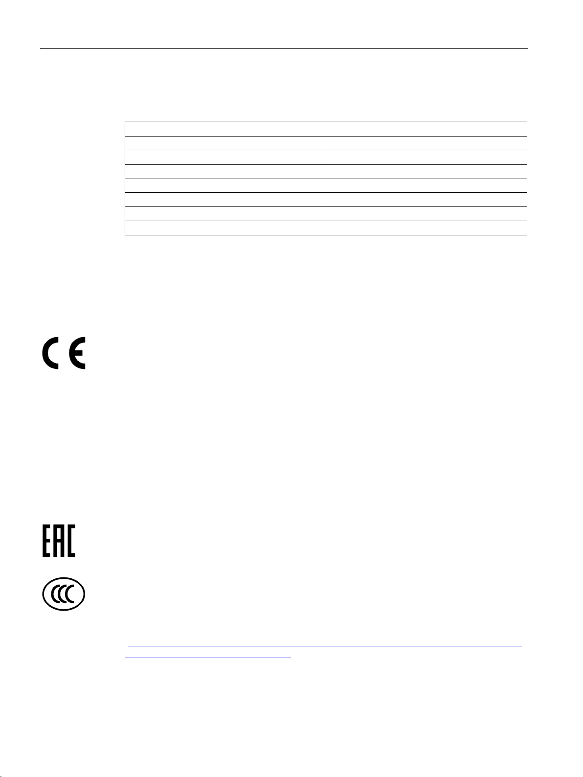
Relevant directives
European Low-Voltage Directive
European Machinery Directive
European EMC Directive
Eurasian conformity
China Compulsory Certification
2.3 Technical features and environmental conditions
Where applicable, the SIMOTICS motor series are in conformance with the following parts of
IEC / EN 60034:
Cooling 1) IEC / EN 60034-6
Connection designations IEC / EN 60034-8
The following directives are relevant for SIMOTICS motors.
SIMOTICS motors comply with the Low-Voltage Directive 2014/35/EU.
SIMOTICS motors do not fall within the scope covered by the Machinery Directive.
However, the use of the products in a typical machine application has been fully assessed
for compliance with the main regulations in this directive concerning health and safety.
SIMOTICS motors do not fall within the scope covered by the EMC Directive. The products
are not considered as devices in the sense of the directive. Installed and operated with a
converter, the motor – together with the Power Drive System – must comply with the
requirements laid down in the applicable EMC Directive.
SIMOTICS motors comply with the requirements of the Russia/Belarus/Kazakhstan (EAC)
customs union.
SIMOTICS motors do not fall within the scope covered by the China Compulsory
Certification (CCC).
CCC negative certification:
CCC product certification
(https://support.industry.siemens.com/cs/products?search=CCC&dtp=Certificate&mfn=ps&o
=DefaultRankingDesc&pnid=13347&lc)
1FN3 linear motors
28 Configuration Manual, 10/2018, 6SN1197-0AB86-0BP2
Page 31

Description of the motor
Underwriters Laboratories
Quality systems
European RoHS Directive
European Directive on Waste Electrical and Electronic Equipment (WEEE)
2.3.2
Danger from strong magnetic fields
Occurrence of magnetic fields
2.3 Technical features and environmental conditions
SIMOTICS motors are generally in compliance with UL and cUL as components of motor
applications, and are appropriately listed.
Specifically developed motors and functions are the exceptions in this case. Here, it is
important that you carefully observe the contents of the quotation and that there is a cUL
mark on the rating plate!
Siemens AG employs a quality management system that meets the requirements of
ISO 9001 and ISO 14001.
Certificates for SIMOTICS motors can be downloaded from the Internet at the following link:
Certificates for SIMOTICS motors
(https://support.industry.siemens.com/cs/ww/de/ps/13347/cert)
The SIMOTICS motor series complies with the Directive 2011/65/EU regarding limiting the
use of certain hazardous substances.
The SIMOTICS motor series complies with the 2012/19/EU directive on taking back and
recycling waste electrical and electronic equipment.
Motor components with permanent magnets generate very strong magnetic fields. In the
no-current condition, the magnetic field strength of the motors comes exclusively from the
magnetic fields of components equipped with permanent magnets. Additional
electromagnetic fields occur in operation.
1FN3 linear motors
Configuration Manual, 10/2018, 6SN1197-0AB86-0BP2
29
Page 32

Description of the motor
Components with permanent magnets
2.3 Technical features and environmental conditions
For the linear motors described in this manual, the permanent magnets are in the secondary
sections.
Figure 2-1 Secondary section with permanent magnets
Figure 2-2 Schematic representation of the static magnetic field of a secondary section, depending
on distance
1FN3 linear motors
30 Configuration Manual, 10/2018, 6SN1197-0AB86-0BP2
Page 33

Description of the motor
Risk to persons as a result of strong magnetic fields
WARNING
Risk of death as a result of permanent magnet fields
CAUTION
Handling secondary sections
WARNING
Risk of electric shock
2.3 Technical features and environmental conditions
Even when the motor is switched off, the permanent magnets can put people with active
medical implants at risk if they are close to the motor.
Examples of active medical implants include: Heart pacemakers, insulin pumps.
• As the affected person, maintain a minimum distance of 500 mm from the permanent
magnets (trigger threshold for static magnetic fields of 0.5 mT as per directive
2013/35/EU).
With regard to the effect of strong magnetic fields on people, the DGUV rule 103-013
"Electromagnetic Fields" of the German Social Accident Insurance applies in Germany.
This rule specifies all the requirements that must be observed in the workplace. In other
countries, the relevant applicable national and local regulations and requirements must be
taken into account.
When dealing with magnetic fields, you must consider the requirements of DGUV rule
103-013 of the German Social Accident Insurance.
The magnetic fields of the secondary sections are permanent. When you come into direct
bodily contact with the secondary sections, a static magnetic flux density of 2 T is not
exceeded.
• Observe DGUV rule 103-013, § 14 "Systems with high static magnetic fields".
Voltage is induced at the power connections of the primary section each time a primary
section moves with respect to a secondary section – and vice versa. If you touch the power
connections you may suffer an electric shock.
• Do not touch the power connections.
• Connect the motor cable ports correctly, or insulate them properly.
1FN3 linear motors
Configuration Manual, 10/2018, 6SN1197-0AB86-0BP2
31
Page 34

Description of the motor
WARNING
Danger of crushing by permanent magnets of the secondary section
made of solid, non-magnetizable material (e.g. hard wood).
2.3 Technical features and environmental conditions
The forces of attraction of magnetic secondary sections act on materials that can be
magnetized. The forces of attraction increase significantly close to the secondary section.
The trigger threshold of 3 mT for a risk of injury due to attraction and projectile effect is
reached at a distance of 150 mm (directive 2013/35/EU). Secondary sections and materials
that can be magnetized can suddenly slam together unintentionally. Two secondary
sections can also unintentionally slam together.
There is a significant risk of crushing when you are close to a secondary section.
Close to the secondary section, the forces of attraction can be several kN - example:
Magnetic attractive forces are equivalent to a force of 100 kg, which is sufficient to trap a
body part.
• Do not underestimate the strength of the attractive forces, and work very carefully.
• Wear safety gloves.
• The work should be done by at least two people.
• Do not unpack the secondary section until immediately before assembly.
• Never unpack several secondary sections at the same time.
• Never place secondary sections next to one another without taking the appropriate
precautions.
• Never place any metals on magnetic surfaces and vice versa.
• Never carry any objects made of magnetizable materials (for example watches, steel or
iron tools) and/or permanent magnets close to the secondary section! If tools that can
be magnetized are nevertheless required, then hold the tool firmly using both hands.
Slowly bring the tool to the secondary section.
• Immediately mount the secondary section that has just been unpacked.
• Always comply with the specified procedure.
• Avoid inadvertently traversing direct drives.
• Keep the following tools at hand to release parts of the body (hand, fingers, foot etc.)
trapped between two components:
– A hammer (about 3 kg) made of solid, non-magnetizable material
– Two pointed wedges (wedge angle approx. 10° to 15°, minimum height 50 mm)
1FN3 linear motors
32 Configuration Manual, 10/2018, 6SN1197-0AB86-0BP2
Page 35

Description of the motor
First aid in the case of accidents involving permanent magnets
Material damage caused by strong magnetic fields
NOTICE
Data loss caused by strong magnetic fields
2.3 Technical features and environmental conditions
● Stay calm.
● If the machine is energized, press the emergency stop switch and open the main switch if
necessary.
● Administer FIRST AID. Call for further help if required.
● To free jammed parts of the body (e.g. hands, fingers, feet), pull apart components that
are clamped together.
– Do this using the non-magnetic hammer to drive the non-magnetic wedges into the
separating rift.
– Release the jammed body parts.
● If necessary, call the emergency medical service or an emergency physician.
If you are close to a secondary section (< 150 mm) any magnetic or electronic data medium
as well as electronic devices that you are carrying can be destroyed. For example, credit
cards, USB sticks, floppy disks and watches are at risk.
• Do not carry any magnetic/electronic data media and no electronic devices when you
are close to a secondary section!
1FN3 linear motors
Configuration Manual, 10/2018, 6SN1197-0AB86-0BP2
33
Page 36

Description of the motor
2.3.3
Technical features
Technical feature
Design
Motor type
Permanently excited synchronous linear motor
(according to DIN 44081/44082)
(according to EN 60751)
2nd rating plate
Enclosed separately
sections
EN 60034-1
(IEC 60034-18-41)
1FN3100-xW ... 1FN3900-xW
2.3 Technical features and environmental conditions
Table 2- 1 Standard version of the 1FN3 range of motors: Technical features
Type of construction Individual components
Degree of protection
according to EN 60034-5
Cooling method Water cooling
Thermal motor protection In the primary section:
• Primary section: IP65
• Mounted motor: The degree of protection depends on the
machine design and must therefore be realized by the machine
manufacturer; minimum requirement: IP23
• Maximum pressure in the cooling circuit: 10 bar = 1 MPa
• Wiring: with G1/8 pipe thread (in compliance with
DIN EN ISO 228-1); special connectors are required to connect
hoses/pipes
1x PTC for thermistor triplet with response threshold +120 °C
Temperature monitoring In the primary section:
1FN3xxx-xxxxx-xxx1 with 1 x KTY 84
(according to EN 60034-11)
1FN3xxx-xxxxx-xxx3 with 1 x Pt1000
Nameplate for secondary
Insulation class of motor
winding according to
Impulse withstand voltage
insulation class according to
EN 60034-18-41
Magnet material Rare earth material
Connection, electrical 1FN3050:
Enclosed separately
Temperature class 155 (F)
IVIC: C
Signal and power cables with connectors or open core ends
permanently connected to the motor
1FN3100 ... 1FN3900:
Terminal panel with cover integrated in the motor, with metric cable
glands for signal and power cables. Additional cover with heavygauge threaded joint for combined cables for
Encoder system
1FN3 linear motors
34 Configuration Manual, 10/2018, 6SN1197-0AB86-0BP2
• Not included in the scope of supply
• Selection based on application-specific and converter-specific
constraints
Page 37

Description of the motor
2.3.4
Direction of motion of the motor
Defining the traversing direction
2.3 Technical features and environmental conditions
If the primary section is connected to the terminals of the terminal box with the phase
sequence U-V-W and is supplied with current by a three-phase system with a clockwise
rotating field, the direction of motion of the primary or secondary section is positive.
1FN3 linear motors
Configuration Manual, 10/2018, 6SN1197-0AB86-0BP2
35
Page 38

Description of the motor
2.3.5
Ambient conditions for stationary use
Ambient conditions are based on climate class 3K3
Ambient parameter
Unit
Value
a)
Low air temperature
°C
- 5
c)
Low relative humidity
%
5
d)
High relative humidity
%
85
e)
Low absolute humidity
g/m3
1
f)
High absolute humidity
g/m3
25
g)
Rate of temperature change1)
°C/min
0.5
h)
Low air pressure4)
kPa
78.4
i)
High air pressure2)
kPa
106
j)
Solar radiation (insolation)
W/m2
700
k)
Thermal radiation
-
-
l)
Air movement3)
m/s
1.0
m)
Condensation
-
Not permissible
(rain, snow, hail, etc.)
protection
p)
Formation of ice
-
-
1)
2)
3)
4)
The limit value of 78.4 KPa covers altitudes up to 2000 m.
Mechanical ambient conditions
Class 3M3
2.3 Technical features and environmental conditions
You can classify the ambient conditions for stationary use at weatherprotected locations
according to the standard DIN IEC 60721-3-3. The environmental effects and their limit
values are defined in various classes in this standard.
With the exception of "Low air temperature" and "Low air pressure" ambient parameters,
you can assign the motors to climatic class 3K3.
Table 2- 2
b) High air temperature °C + 40
n) Wind-driven precipitation
o) Water (other than rain) - See degree of
- -
Averaged over a period of 5 min
Conditions in mines are not considered.
A cooling system based on natural convection can be disturbed by unforeseen air movements.
Additional ambient conditions applicable for the motors for stationary use at weatherprotected locations according to standard DIN IEC 60721-3-3 include.
Mechanically active ambient conditions Class 3S1
1FN3 linear motors
36 Configuration Manual, 10/2018, 6SN1197-0AB86-0BP2
Page 39

Description of the motor
Note
Installation instructions
The motors are not suitable for operation
•
•
2.3.6
Scope of delivery
2.3.6.1
Scope of delivery linear motor
Primary section
Secondary section
Note
Nameplates for secondary sections
The
or to the secondary section cover. Apply the nameplates for secondary sections in a clearly
visible position next to the secondary section track or in the vicinity of t
2.3 Technical features and environmental conditions
In salt-laden or corrosive atmospheres
Outdoors
You can find additional data on the environmental conditions, such as ambient temperatures
or conditions for transport and storage of the motors, in the relevant chapters of this
documentation.
● Primary section
● One rating plate (attached); additional loose rating plate
● Accessory pack note (safety accessory pack)
● Safety warning instructions (pictograms)
● For the terminal box design: Accessories (mounting accessories) for the terminal box with
● Secondary section
● A nameplate included as a separate item
● Accessory pack note (safety accessory pack)
● Safety warning instructions (pictograms)
terminal cover and enclosed information slip with terminal assignments
nameplates for secondary sections are not suitable for applying to a secondary section
1FN3 linear motors
Configuration Manual, 10/2018, 6SN1197-0AB86-0BP2
he motor.
37
Page 40

Description of the motor
2.3.6.2
Supplied pictograms
Primary sections
Sign
Meaning
Sign
Meaning
Sign
Meaning
Sign
Meaning
Secondary sections
Sign
Meaning
Sign
Meaning
2.3 Technical features and environmental conditions
To identify hazards, warning signs in the form of permanent adhesive stickers are enclosed
with all primary sections in the packaging:
Table 2- 3 Warning signs included with primary sections according to BGV A8 and EN ISO 7010
and their meaning
Warning against
hot surface
(W017)
Warning against
electric voltage
(W012)
The following safety instructions are attached at the signal port of the primary section:
Table 2- 4 Safety instructions for temperature protection according to BGV A8 and EN ISO 7010
and their significance
General
warning sign
(W001)
Observe
instruction
(M002)
To identify hazards, warning and prohibition signs in the form of permanent adhesive stickers
are enclosed with all secondary sections in the packaging:
Table 2- 5 Warning signs according to BGV A8 and EN ISO 7010 included with secondary sections
and their meaning
Warning: strong
magnetic field
(W006)
Warning:
hand injuries
(W024)
1FN3 linear motors
38 Configuration Manual, 10/2018, 6SN1197-0AB86-0BP2
Page 41

Description of the motor
Sign
Meaning
Sign
Meaning
Note
Applying the stickers
The stickers are not suitable for applying to a secondary section or on the secondary section
cover.
•
Note
The quality of the label can diminish as result of extreme environmental conditions.
2.3 Technical features and environmental conditions
Table 2- 6 Prohibiting signs according to BGV A8 and EN ISO 7010 included with secondary
sections and their meaning
No access for persons
with pacemakers or
implanted defibrillators
(P007)
No metal objects or
watches
(P008)
No access for persons
with metal implants
(P014)
Apply the stickers next to the secondary section track in the vicinity of the motor so that
they are clearly visible.
Any danger areas encountered during normal operation and when maintaining and servicing
the motor must be identified using clearly visible warning and prohibit signs (pictograms) in
the immediate vicinity of the danger (close to the motor). The associated texts must be
available in the language of the country in which the product is used.
1FN3 linear motors
Configuration Manual, 10/2018, 6SN1197-0AB86-0BP2
39
Page 42

Description of the motor
2.4
Derating factors
Installation altitude above sea level in m up to
Factor
2000
1
4000
0.775
5000
0.656
6000
0.588
7000
0.513
8000
0.444
2.5
Selection and ordering data
2.5.1
Order designation
2.4 Derating factors
For installation altitudes above 2000 m above sea level, reduce the voltage stress of the
motors according to table "Factors to reduce the maximum DC link voltage" (reciprocal
values from EN 60664-1 Table A. 2).
Table 2- 7 Factors to reduce the maximum DC link voltage
3000 0.877
Reducing the DC link voltage reduces the converter output voltage. The operating range in
the F-v diagram is thus also reduced.
You can find the F-v diagrams in the associated data sheet.
Operation in a vacuum is not permissible due to the low voltage strength and the poor
cooling.
The article number is used as the order designation. The article number consists of a
combination of letters and numerals. When placing an order, it is sufficient just to specify the
unique article number.
The article number consists of three blocks that are separated by hyphens. The first block
incorporates seven characters and designates the product family and size of the primary or
secondary section. Additional design features are encrypted in the second block, such as
length and velocity. The third block is provided for additional data.
Please note that not every theoretical combination is possible.
1FN3 linear motors
40 Configuration Manual, 10/2018, 6SN1197-0AB86-0BP2
Page 43

Description of the motor
2.5.1.1
Primary sections
2.5.1.2
Secondary sections
2.5 Selection and ordering data
1FN3 linear motors
Configuration Manual, 10/2018, 6SN1197-0AB86-0BP2
41
Page 44

Description of the motor
2.5.1.3
Primary section accessories
Precision cooler
Hall sensor box
2.5 Selection and ordering data
The Hall sensor box can be mounted opposite to the primary section’s terminal end or on the
terminal end of the primary section. The standard location is opposite to the primary
section’s terminal end.
1FN3 linear motors
42 Configuration Manual, 10/2018, 6SN1197-0AB86-0BP2
Page 45

Description of the motor
Connection cover
Connection cover
Primary section size
Thread for gland
1FN3002-0PB01-0AA0
1FN3100 and 1FN3150
1 x PG16
1FN3003-0PB02-0AA0
1FN3300 to 1FN3900
1 x PG21
1FN3003-0PB03-0AA0
1FN3300 to 1FN3900
1 x PG29
1FN3002-0PB04-0BA0
1FN3100 and 1FN3150
2 x M20 x 1.5
1FN3003-0PB04-0BA0
1FN3300 to 1FN3900
2 x M20 x 1.5
1FN3003-0PB05-0BA0
1FN3300 to 1FN3900
1 x M20 x 1.5 and 1 x M32 x 1.5
Plug connector
Connector type
Connector size
Article No.
Power connection
1.5
6FX2003-0LA10
Power connection
1
6FX2003-0LA00
Signal connection
M17
6FX2003-0SU07
2.5 Selection and ordering data
For 1FN3 linear motors, all of the connection covers can also be separately ordered.
Table 2- 8 Article numbers
1FN3 linear motors
Configuration Manual, 10/2018, 6SN1197-0AB86-0BP2
43
Page 46

Description of the motor
2.5.1.4
Accessories for the secondary section track
Secondary section end pieces
Secondary section cover
Segmented cover
2.5 Selection and ordering data
1FN3 linear motors
44 Configuration Manual, 10/2018, 6SN1197-0AB86-0BP2
Page 47

Description of the motor
Cover with metal strip
Cooling sections
2.5 Selection and ordering data
1FN3 linear motors
Configuration Manual, 10/2018, 6SN1197-0AB86-0BP2
45
Page 48

Description of the motor
Overview of heatsink profiles
For sizes
1FN3050
1FN3100
1FN3150
For sizes
1FN3300
1FN3450
For sizes
1FN3600
For sizes
1FN3900
"left"
"left"
2.5 Selection and ordering data
Table 2- 9 Heatsink profiles – variants and lengths that can be ordered
Lengths: None available
Lengths: 01 to 24 segments
Length: 11 segments
Lengths: 01 to 24 segments
Length: only 02 segments
Length: 3000 mm
Lengths: 01 to 16 segments
Lengths:
04, 05, 07, 09, 11 segments
Lengths: 01 to 16 segments
Length: only 02 segments
Length: 3000 mm
Lengths: 01 to 16 segments
Length: only 05 segments
Lengths: 01 to 16 segments
Length: only 02 segments
Length: 3000 mm
Lengths: 01 to 16 segments
Length: only 04 segments
Lengths: 01 to 16 segments
Length: only 02 segments
"right"
Length: only 02 segments
1FN3 linear motors
46 Configuration Manual, 10/2018, 6SN1197-0AB86-0BP2
Length: only 02 segments
"right"
Page 49

Description of the motor
2.5.1.5
Ordering examples
Ordering example of a peak or continuous load motor
Peak load motor
Continuous load motor
Component
Quantity
Article No.
Article No.
Primary section precision cooler
1
1FN3150–3PK00–0AA0
1FN3150–3PK10–0AA0
band)
coupling
Combi distributor 2 1FN3150–0TJ01–0AA0
(standard, straight cable outlet)
Ordering examples of heatsink profiles
2.5 Selection and ordering data
If you have any questions on configuring, contact your local Siemens office.
Table 2- 10
Primary section 1 1FN3150–3WC00–0BA1 1FN3150–3NC70–0BA1
Secondary sections
(length of the secondary section
track: 1,440 mm)
Secondary section cover (metal
Heatsink profiles with plug-type
Hall sensor box
12 1FN3150–4SA00–0AA0
1 1FN3150–0TB00–1BC0
2 1FN3002–0TK04–1BC0
1 1FN3005–0PH00–0AA0
In the following ordering examples, the article numbers of the heatsink profile in question is
provided directly in the drawings. If you have any questions on heatsink profiles, contact your
local Siemens office.
Ordering examples of heatsink profiles with a plug-type coupling and for connection to a
combi distributor with a plug-type coupling are shown below. The relevant article numbers for
the secondary section end pieces with combi distributors are also shown in the drawings,
e.g. 1FN3050-0TJ01-0AA0.
Figure 2-3 Heatsink profiles for secondary section track sizes 1FN3050-4SA00-0AA0,
1FN3100-4SA00-0AA01, 1FN3150-4SA00-0AA0
1FN3 linear motors
Configuration Manual, 10/2018, 6SN1197-0AB86-0BP2
47
Page 50

Description of the motor
2.5 Selection and ordering data
Figure 2-4 Heatsink profiles for secondary section track sizes 1FN3300-4SA00-0AA0,
1FN3450-4SA00-0AA0
Figure 2-5 Heatsink profiles for secondary section track size 1FN3600-4SA00-0AA0
Figure 2-6 Heatsink profiles for secondary section track size 1FN3900-4SA00-0AA0
The following ordering examples show serially connected heatsink profiles that are
connected via plug-type couplings. For connecting plastic hoses to the outer heatsink
profiles, hose connector nipples are provided.
1FN3 linear motors
48 Configuration Manual, 10/2018, 6SN1197-0AB86-0BP2
Page 51

Description of the motor
2.5 Selection and ordering data
Figure 2-7 Heatsink profiles for secondary section track sizes 1FN3050-4SA00-0AA0,
1FN3100-4SA00-0AA0, 1FN3150-4SA00-0AA0
Figure 2-8 Heatsink profiles for secondary section track sizes 1FN3300-4SA00-0AA0,
1FN3450-4SA00-0AA0
Figure 2-9 Heatsink profiles for secondary section track size 1FN3600-4SA00-0AA0
Figure 2-10 Heatsink profiles for secondary section track size 1FN3900-4SA00-0AA0
1FN3 linear motors
Configuration Manual, 10/2018, 6SN1197-0AB86-0BP2
49
Page 52

Description of the motor
2.5.2
Selection and ordering data 1FN3
Note
Overview of important motor data
A selection of important motor data and dimensions is provided in this chapter. All of the data
sheets are provided in Chapter "
Chapter "
Overview of important data of the peak load motors of the 1FN3 product family
Article No. Primary section
FN
in N
F
MAX
in N
IN
in A
I
MAX
in A
v
MAX,FN
in m/min
v
MAX,FMAX
in m/min
P
V,N
in kW
1FN3050-2WC00-0xAx
200
550
2.72
8.15
408
170
0.275
1FN3100-1WC00-0xAx
200
490
2.44
6.5
335
147
0.269
1FN3100-2WC00-0xAx
450
1100
5.08
13.5
323
148
0.501
1FN3100-2WE00-0xAx
450
1100
8.04
21.4
535
258
0.501
1FN3100-2WJ20-0xAx
450
1100
14.4
38.3
984
488
0.502
1FN3100-3WC00-0xAx
675
1650
7.18
19.1
303
137
0.748
1FN3100-3WE00-0xAx
675
1650
12.1
32.1
534
258
0.749
1FN3100-4WC00-0xAx
900
2200
10.2
27.1
324
148
0.998
1FN3100-4WE00-0xAx
900
2200
16.1
42.9
535
258
0.999
1FN3100-5WC00-0xAx
1120
2750
11
29.5
278
125
1.2
1FN3150-1WC00-0xAx
340
820
3.58
9.54
303
140
0.337
1FN3150-1WE00-0xAx
340
820
6.41
17.1
569
278
0.338
1FN3150-2WC00-0xAx
675
1650
7.16
19.1
306
141
0.671
1FN3150-3WC00-0xAx
1010
2470
10.7
28.6
302
138
1.01
1FN3150-4WC00-0xAx
1350
3300
14.3
38.2
306
141
1.34
1FN3150-5WC00-0xAx
1690
4120
17.9
47.7
306
141
1.67
1FN3300-1WC00-0xAx
610
1720
6.47
20
325
138
0.45
1FN3300-2WB00-0xAx
1220
3450
7.96
24.7
194
76.5
0.85
1FN3300-2WC00-0xAx
1230
3450
12.6
39
322
140
0.852
1FN3300-2WG00-0xAx
1230
3450
32.4
100
868
399
0.812
1FN3300-3WC00-0xAx
1840
5170
19.2
59.5
327
142
1.32
1FN3300-3WG00-0xAx
1840
5170
49.4
153
881
405
1.25
1FN3300-4WB00-0xAx
2450
6900
16
49.4
194
76.7
1.71
2.5 Selection and ordering data
Technical data and characteristics (Page 165)" and in
Assembly drawings/dimension sheets (Page 509)".
The following tables provide an overview of the most important data of the peak load motors
of the 1FN3 product family. For the mass and size, models with and without optional
precision cooling elements are listed.
Table 2- 11 Overview of the most important data of the peak load motors of the 1FN3 product family / Part 1
1FN3 linear motors
50 Configuration Manual, 10/2018, 6SN1197-0AB86-0BP2
Page 53

Description of the motor
Article No. Primary section
FN
in N
F
MAX
in N
IN
in A
I
MAX
in A
v
MAX,FN
in m/min
v
MAX,FMAX
in m/min
P
V,N
in kW
1FN3300-4WC00-0xAx
2450
6900
25.3
78.3
323
140
1.71
1FN3450-2WA50-0xAx
1930
5180
8.91
25
120
41
1.47
1FN3450-2WB70-0xAx
1930
5180
16.2
45.4
238
103
1.49
1FN3450-2WC00-0xAx
1930
5180
20
56.2
301
135
1.48
1FN3450-2WD00-0xAx
1930
5180
25
70.2
385
177
1.34
1FN3450-2WE00-0xAx
1930
5180
36.3
102
567
264
1.4
1FN3450-3WA50-0xAx
2900
7760
12.9
38
121
40.5
2.03
1FN3450-3WB00-0xAx
2900
7760
17.9
52.8
179
72.7
1.99
1FN3450-3WB50-0xAx
2900
7760
22.9
67.4
236
102
1.98
1FN3450-3WC00-0xAx
2900
7760
28.3
83.5
298
133
1.97
1FN3450-3WE00-0xAx
2900
7760
51.3
151
561
260
1.86
1FN3450-4WB00-0xAx
3860
10300
23.8
70.1
179
72.9
2.63
1FN3450-4WB50-0xAx
3860
10300
30.3
89.5
236
102
2.62
1FN3450-4WC00-0xAx
3860
10300
37.6
111
298
133
2.6
1FN3450-4WE00-0xAx
3860
10300
68
201
560
261
2.45
1FN3600-2WA50-0xAx
2610
6900
13.2
35.9
128
45.4
2.19
1FN3600-2WB00-0xAx
2610
6900
16.8
45.8
172
69.6
2.18
1FN3600-2WB50-0xAx
2610
6900
22.3
60.7
238
105
2.09
1FN3600-2WC00-0xAx
2610
6900
26.1
70.9
283
128
1.95
1FN3600-3WB50-0xAx
3910
10300
32.9
90.5
237
104
3.03
1FN3600-3WB00-0xAx
3920
10300
24.8
68.2
171
69.4
3.15
1FN3600-3WC00-0xAx
3920
10300
38.4
106
282
128
2.83
1FN3600-4WA30-0xAx
5220
13800
22.3
63.7
112
35.5
3.86
1FN3600-4WB00-0xAx
5220
13800
31.5
90.1
170
68.1
3.82
1FN3600-4WD30-0xAx
5220
13800
70.7
202
413
190
3.56
1FN3600-5WB00-0xAx
6530
17200
42.7
114
171
69.6
5.61
1FN3900-2WB00-0xAx
4050
10300
25.5
70.5
179
78
2.63
1FN3900-2WC00-0xAx
4050
10300
37
102
269
123
2.74
1FN3900-3WB00-0xAx
6080
15500
40.6
114
188
78.7
4.42
1FN3900-4WA50-0xAx
8100
20700
30.7
86.3
98.9
31.1
5.52
1FN3900-4WB00-0xAx
8100
20700
49.7
140
178
77.2
4.98
1FN3900-4WB50-0xAx
8100
20700
61.4
173
222
98.6
5.53
1FN3900-4WC00-0xAx
8100
20700
72
202
266
122
5.19
F
F
I
I
v
force, v
MAX,FMAX
= maximum velocity at maximum force, P
V,N
= power loss at the rated point
2.5 Selection and ordering data
1FN3600-4WB50-0xAx 5220 13800 41.8 120 234 102 3.67
1FN3600-4WC00-0xAx 5220 13800 48.8 139 279 125 3.42
= rated force,
N
1FN3 linear motors
Configuration Manual, 10/2018, 6SN1197-0AB86-0BP2
= maximum force,
MAX
= rated current,
N
= maximum current,
MAX
= maximum velocity at rated
MAX,FN
51
Page 54

Description of the motor
Article No. Primary section
h
M3
/ hM1
in mm
bP / b
PK1
in mm
lP
in mm
l
P,AKT
in mm
mP / m
P,P
in kg
lS
in mm
mS / m
S,P
in kg
1FN3050-2WC00-0xAx
48.5 / 63.4
67 / 76
255
210
3 / 3.5
120
0.4 / 0.5
1FN3100-1WC00-0xAx
48.5 /
96 /
150
105
2 / 2
120
0.7 / 0.8
1FN3100-2WC00-0xAx
48.5 / 63.4
96 / 105
255
210
4 / 4.6
120
0.7 / 0.8
1FN3100-2WE00-0xAx
48.5 / 63.4
96 / 105
255
210
4 / 4.6
120
0.7 / 0.8
1FN3100-2WJ20-0xAx
48.5 / 63.4
96 / 105
255
210
4 / 4.6
120
0.7 / 0.8
1FN3100-3WC00-0xAx
48.5 / 63.4
96 / 105
360
315
5.6 / 6.4
120
0.7 / 0.8
1FN3100-3WE00-0xAx
48.5 / 63.4
96 / 105
360
315
5.6 / 6.4
120
0.7 / 0.8
1FN3100-4WC00-0xAx
48.5 / 63.4
96 / 105
465
420
7.4 / 8.5
120
0.7 / 0.8
1FN3100-4WE00-0xAx
48.5 / 63.4
96 / 105
465
420
7.4 / 8.5
120
0.7 / 0.8
1FN3100-5WC00-0xAx
48.5 / 63.4
96 / 105
570
525
9.1 / 10.4
120
0.7 / 0.8
1FN3150-1WC00-0xAx
50.5 /
126 /
150
105
2.9 / 3.4
120
1.2 / 1.3
1FN3150-1WE00-0xAx
50.5 /
126 /
150
105
2.9 / 3.4
120
1.2 / 1.3
1FN3150-2WC00-0xAx
50.5 / 65.4
126 / 135
255
210
5.3 / 6
120
1.2 / 1.3
1FN3150-3WC00-0xAx
50.5 / 65.4
126 / 135
360
315
7.7 / 8.6
120
1.2 / 1.3
1FN3150-4WC00-0xAx
50.5 / 65.4
126 / 135
465
420
10.4 / 11.6
120
1.2 / 1.3
1FN3150-5WC00-0xAx
50.5 / 65.4
126 / 135
570
525
12.5 / 13.9
120
1.2 / 1.3
1FN3300-1WC00-0xAx
64.1 /
141 /
221
161
6.6 / 7
184
2.4 / 2.6
1FN3300-2WB00-0xAx
64.1 / 79
141 / 151
382
322
11.5 / 12.5
184
2.4 / 2.6
1FN3300-2WC00-0xAx
64.1 / 79
141 / 151
382
322
11.5 / 12.5
184
2.4 / 2.6
1FN3300-2WG00-0xAx
64.1 / 79
141 / 151
382
322
11.5 / 12.5
184
2.4 / 2.6
1FN3300-3WC00-0xAx
64.1 / 79
141 / 151
543
483
17 / 18.4
184
2.4 / 2.6
1FN3300-3WG00-0xAx
64.1 / 79
141 / 151
543
483
17 / 18.4
184
2.4 / 2.6
1FN3300-4WB00-0xAx
64.1 / 79
141 / 151
704
644
22.2 / 24
184
2.4 / 2.6
1FN3300-4WC00-0xAx
64.1 / 79
141 / 151
704
644
22.2 / 24
184
2.4 / 2.6
1FN3450-2WC00-0xAx
66.1 / 81
188 / 197
382
322
16.5 / 17.7
184
3.8 / 4
1FN3450-2WD00-0xAx
66.1 / 81
188 / 197
382
322
16.5 / 17.7
184
3.8 / 4
1FN3450-2WE00-0xAx
66.1 / 81
188 / 197
382
322
16.5 / 17.7
184
3.8 / 4
1FN3450-3WA50-0xAx
66.1 / 81
188 / 197
543
483
24 / 25.7
184
3.8 / 4
1FN3450-3WB00-0xAx
66.1 / 81
188 / 197
543
483
24 / 25.7
184
3.8 / 4
1FN3450-3WB50-0xAx
66.1 / 81
188 / 197
543
483
24 / 25.7
184
3.8 / 4
1FN3450-3WC00-0xAx
66.1 / 81
188 / 197
543
483
24 / 25.7
184
3.8 / 4
1FN3450-3WE00-0xAx
66.1 / 81
188 / 197
543
483
24 / 25.7
184
3.8 / 4
1FN3450-4WB00-0xAx
66.1 / 81
188 / 197
704
644
31.7 / 33.9
184
3.8 / 4
1FN3450-4WB50-0xAx
66.1 / 81
188 / 197
704
644
31.7 / 33.9
184
3.8 / 4
1FN3450-4WC00-0xAx
66.1 / 81
188 / 197
704
644
31.7 / 33.9
184
3.8 / 4
1FN3450-4WE00-0xAx
66.1 / 81
188 / 197
704
644
31.7 / 33.9
184
3.8 / 4
1FN3600-2WA50-0xAx
64.1 / 86
248 / 257
382
322
22.5 / 25
184
4.6 / 5
2.5 Selection and ordering data
Table 2- 12 Overview of the most important data of the peak load motors of the 1FN3 product family / Part 2
1FN3450-2WA50-0xAx 66.1 / 81 188 / 197 382 322 16.5 / 17.7 184 3.8 / 4
1FN3450-2WB70-0xAx 66.1 / 81 188 / 197 382 322 16.5 / 17.7 184 3.8 / 4
1FN3 linear motors
52 Configuration Manual, 10/2018, 6SN1197-0AB86-0BP2
Page 55

Description of the motor
Article No. Primary section
h
M3
/ hM1
in mm
bP / b
PK1
in mm
lP
in mm
l
P,AKT
in mm
mP / m
P,P
in kg
lS
in mm
mS / m
S,P
in kg
1FN3600-2WB00-0xAx
64.1 / 86
248 / 257
382
322
22.5 / 25
184
4.6 / 5
1FN3600-2WB50-0xAx
64.1 / 86
248 / 257
382
322
22.5 / 25
184
4.6 / 5
1FN3600-2WC00-0xAx
64.1 / 86
248 / 257
382
322
22.5 / 25
184
4.6 / 5
1FN3600-3WB50-0xAx
64.1 / 86
248 / 257
543
483
33.5 / 35.4
184
4.6 / 5
1FN3600-3WB00-0xAx
64.1 / 86
248 / 257
543
483
33.5 / 35.4
184
4.6 / 5
1FN3600-3WC00-0xAx
64.1 / 86
248 / 257
543
483
33.5 / 35.4
184
4.6 / 5
1FN3600-4WA30-0xAx
64.1 / 86
248 / 257
704
644
43 / 45.5
184
4.6 / 5
1FN3600-4WB00-0xAx
64.1 / 86
248 / 257
704
644
43 / 45.5
184
4.6 / 5
1FN3600-4WB50-0xAx
64.1 / 86
248 / 257
704
644
43 / 45.5
184
4.6 / 5
1FN3600-4WC00-0xAx
64.1 / 86
248 / 257
704
644
43 / 45.5
184
4.6 / 5
1FN3600-4WD30-0xAx
64.1 / 86
248 / 257
704
644
43 / 45.5
184
4.6 / 5
1FN3600-5WB00-0xAx
64.1 / 86
248 / 257
0 0 56 / 59.1
184
4.6 / 5
1FN3900-2WB00-0xAx
66.1 / 88
342 / 351
382
322
32.2 / 33.7
184
7.5 / 7.9
1FN3900-2WC00-0xAx
66.1 / 88
342 / 351
382
322
32.2 / 33.7
184
7.5 / 7.9
1FN3900-3WB00-0xAx
66.1 / 88
342 / 351
543
483
47.2 / 49.3
184
7.5 / 7.9
1FN3900-4WA50-0xAx
66.1 / 88
342 / 351
704
644
62.7 / 65.4
184
7.5 / 7.9
1FN3900-4WB00-0xAx
66.1 / 88
342 / 351
704
644
62.7 / 65.4
184
7.5 / 7.9
1FN3900-4WB50-0xAx
66.1 / 88
342 / 351
704
644
62.7 / 65.4
184
7.5 / 7.9
1FN3900-4WC00-0xAx
66.1 / 88
342 / 351
704
644
62.7 / 65.4
184
7.5 / 7.9
h
h
bP =
precision cooler, b
l
l
m
m
primary section with precision cooler, l
m
m
S,P
= weight of the secondary section with heatsink profiles
2.5 Selection and ordering data
= motor height without additional heatsinks,
M3
= motor width with precision cooler,
PK1
= magnetically active length of the primary section,
P,AKT
= length of the secondary section,
S
= motor height with additional heatsinks,
M1
= length of the primary section (without connection cover),
P
= weight of the primary primary section,
P
= weight of the secondary section,
S
motor width without
= weight of the
P,P
1FN3 linear motors
Configuration Manual, 10/2018, 6SN1197-0AB86-0BP2
53
Page 56

Description of the motor
Overview of important data of the continuous load motors of the 1FN3 product family
Article No. Primary section
FN
in N
F
MAX
in N
IN
in A
I
MAX
in A
v
MAX,FN
in m/min
v
MAX,FMAX
in m/min
P
V,N
in kW
1FN3050-1ND00-0xAx
151
255
2.82
5.86
429
236
0.16
1FN3050-2NB80-0xAx
302
510
2.82
5.86
199
104
0.318
1FN3050-2NE00-0xAx
302
510
5.65
11.7
419
229
0.318
1FN3100-1NC00-0xAx
302
510
2.82
5.86
212
115
0.253
1FN3100-2NC80-0xAx
604
1020
7.96
16.5
300
164
0.503
1FN3100-3NA80-0xAx
905
1530
4.52
9.39
101
49.1
0.755
1FN3100-3NC00-0xAx
905
1530
8.47
17.6
206
111
0.754
1FN3100-4NC80-0xAx
1210
2040
15.9
33.1
296
162 1 1FN3150-1NC20-0xAx
453
766
4.52
9.38
230
127
0.343
1FN3150-2NB80-0xAx
905
1530
7.96
16.5
197
106
0.681
1FN3150-3NB80-0xAx
1360
2300
11.9
24.8
195
105
1.02
1FN3150-3NC70-0xAx
1360
2300
16.9
35.2
284
156
1.02
1FN3150-4NB80-0xAx
1810
3060
15.9
33.1
195
105
1.36
1FN3300-1NC10-0xAx
864
1470
8.12
17.1
228
127
0.508
1FN3300-2NC10-0xAx
1730
2940
16.2
34.1
224
124
1.01
1FN3300-2NH00-0xAx
1730
2940
49.9
105
715
402
1.08
1FN3300-3NB50-0xAx
2590
4400
17.7
37.1
158
85.5
1.52
1FN3300-3NC40-0xAx
2590
4400
27.3
57.4
252
139
1.52
1FN3300-4NB80-0xAx
3460
5870
28.4
59.6
192
105
2.03
1FN3450-1NB50-0xAx
1300
2200
9.1
19.1
169
93.5
0.693
1FN3450-2NB40-0xAx
2590
4400
16.2
34.1
147
80
1.38
1FN3450-2NB80-0xAx
2590
4400
20.4
42.9
188
104
1.39
1FN3450-2NC50-0xAx
2590
4400
28.4
59.6
266
148
1.39
1FN3450-3NA50-0xAx
3890
6600
12.7
26.7
69.9
34.3
2.08
1FN3450-4NB20-0xAx
5190
8810
28.4
59.6
126
67.5
2.77
1FN3450-4NB80-0xAx
5190
8810
40.8
85.8
186
102
2.77
1FN3600-2NB00-0xAx
3460
5870
16.2
34.1
107
56.8
1.86
1FN3600-2NB80-0xAx
3460
5870
28.4
59.6
197
109
1.87
1FN3600-2NE50-0xAx
3460
5870
64.2
135
460
259
2.06
1FN3600-3NB00-0xAx
5190
8810
30.6
64.4
137
74.3
2.8
1FN3600-3NB80-0xAx
5190
8810
42.5
89.5
196
108
2.8
1FN3600-4NA70-0xAx
6920
11700
26.3
55.3
83.5
42.6
3.72
2.5 Selection and ordering data
The following tables provide an overview of the most important data of the continuous load
motors of the 1FN3 product family. For the mass and size, models with and without optional
precision cooling elements are listed.
Table 2- 13 Overview of the most important data of the continuous load motors of the 1FN3 product family / Part 1
1FN3450-3NB50-0xAx 3890 6600 27.3 57.4 165 90.5 2.07
1FN3450-3NC50-0xAx 3890 6600 42.5 89.5 264 147 2.08
1FN3 linear motors
54 Configuration Manual, 10/2018, 6SN1197-0AB86-0BP2
Page 57

Description of the motor
Article No. Primary section
FN
in N
F
MAX
in N
IN
in A
I
MAX
in A
v
MAX,FN
in m/min
v
MAX,FMAX
in m/min
P
V,N
in kW
1FN3600-4NB80-0xAx
6920
11700
56.7
119
195
108
3.74
1FN3900-2NB20-0xAx
5190
8810
28.4
59.6
128
69.4
2.65
1FN3900-2NC80-0xAx
5190
8810
64.2
135
304
170
2.89
1FN3900-3NB20-0xAx
7780
13200
42.5
89.5
127
68.9
3.97
1FN3900-4NA50-0xAx
10400
17600
29.3
61.6
59.4
28.2
5.26
1FN3900-4NA80-0xAx
10400
17600
40.8
85.8
87.9
45.6
5.28
1FN3900-4NB20-0xAx
10400
17600
56.7
119
127
68.6
5.29
F
F
I
I
v
force, v
MAX,FMAX
= maximum velocity at maximum force, P
V,N
= power loss at the rated point
Article No. Primary section
h
M3
/ hM1
in mm
bP / b
PK1
in mm
lP
in mm
l
P,AKT
in mm
mP / m
P,P
in kg
lS
in mm
mS / m
S,P
in kg
1FN3050-1ND00-0xAx
59.4 / 74.3
67 / 76
162
117
2.2 / 2.69
120
0.4 / 0.5
1FN3050-2NB80-0xAx
59.4 / 74.3
67 / 76
267
222
3.9 / 4.6
120
0.4 / 0.5
1FN3050-2NE00-0xAx
59.4 / 74.3
67 / 76
267
222
3.9 / 4.6
120
0.4 / 0.5
1FN3100-1NC00-0xAx
59.4 / 74.3
96 / 105
162
117
3 / 3.52
120
0.7 / 0.8
1FN3100-2NC80-0xAx
59.4 / 74.3
96 / 105
267
222
5.4 / 6.19
120
0.7 / 0.8
1FN3100-3NA80-0xAx
59.4 / 74.3
96 / 105
372
327
7.5 / 8.56
120
0.7 / 0.8
1FN3100-3NC00-0xAx
59.4 / 74.3
96 / 105
372
327
7.5 / 8.56
120
0.7 / 0.8
1FN3100-4NC80-0xAx
59.4 / 74.3
96 / 105
477
432
9.9 / 11.2
120
0.7 / 0.8
1FN3150-1NC20-0xAx
61.4 / 76.3
126 / 135
162
117
4 / 4.5
120
1.2 / 1.3
1FN3150-2NB80-0xAx
61.4 / 76.3
126 / 135
267
222
7.3 / 8.15
120
1.2 / 1.3
1FN3150-3NB80-0xAx
61.4 / 76.3
126 / 135
372
327
10.5 / 11.7
120
1.2 / 1.3
1FN3300-2NH00-0xAx
78 / 92.9
141 / 151
399
340
15.9 / 17
184
2.4 / 2.6
1FN3300-3NB50-0xAx
78 / 92.9
141 / 151
560
501
23 / 24.4
184
2.4 / 2.6
1FN3300-4NB80-0xAx
78 / 92.9
141 / 151
721
662
29.9 / 31.8
184
2.4 / 2.6
1FN3450-1NB50-0xAx
80 / 94.9
188 / 197
238
179
12 / 12.8
184
3.8 / 4
1FN3450-2NB40-0xAx
80 / 94.9
188 / 197
399
340
22.5 / 23.7
184
3.8 / 4
1FN3450-2NB80-0xAx
80 / 94.9
188 / 197
399
340
22.5 / 23.7
184
3.8 / 4
1FN3450-2NC50-0xAx
80 / 94.9
188 / 197
399
340
22.5 / 23.7
184
3.8 / 4
1FN3450-3NA50-0xAx
80 / 94.9
188 / 197
560
501
32.7 / 34.3
184
3.8 / 4
1FN3450-3NB50-0xAx
80 / 94.9
188 / 197
560
501
32.7 / 34.3
184
3.8 / 4
1FN3450-3NC50-0xAx
80 / 94.9
188 / 197
560
501
32.7 / 34.3
184
3.8 / 4
2.5 Selection and ordering data
= rated force,
N
= maximum force,
MAX
= rated current,
N
= maximum current,
MAX
= maximum velocity at rated
MAX,FN
Table 2- 14 Overview of the most important data of the continuous load motors of the 1FN3 product family / Part 2
1FN3150-3NC70-0xAx 61.4 / 76.3 126 / 135 372 327 10.5 / 11.7 120 1.2 / 1.3
1FN3150-4NB80-0xAx 61.4 / 76.3 126 / 135 477 432 13.9 / 15.3 120 1.2 / 1.3
1FN3300-1NC10-0xAx 78 / 92.9 141 / 151 238 179 8.8 / 9.51 184 2.4 / 2.6
1FN3300-2NC10-0xAx 78 / 92.9 141 / 151 399 340 15.9 / 17 184 2.4 / 2.6
1FN3300-3NC40-0xAx 78 / 92.9 141 / 151 560 501 23 / 24.4 184 2.4 / 2.6
1FN3 linear motors
Configuration Manual, 10/2018, 6SN1197-0AB86-0BP2
55
Page 58

Description of the motor
Article No. Primary section
h
M3
/ hM1
in mm
bP / b
PK1
in mm
lP
in mm
l
P,AKT
in mm
mP / m
P,P
in kg
lS
in mm
mS / m
S,P
in kg
1FN3450-4NB20-0xAx
80 / 94.9
188 / 197
721
662
42 / 44
184
3.8 / 4
1FN3450-4NB80-0xAx
80 / 94.9
188 / 197
721
662
42 / 44
184
3.8 / 4
1FN3600-2NB00-0xAx
78 / 99.9
248 / 257
399
340
30.4 / 32
184
4.6 / 5
1FN3600-2NB80-0xAx
78 / 99.9
248 / 257
399
340
30.4 / 32
184
4.6 / 5
1FN3600-2NE50-0xAx
78 / 99.9
248 / 257
399
340
30.4 / 32
184
4.6 / 5
1FN3600-3NB00-0xAx
78 / 99.9
248 / 257
560
501
44.3 / 46.4
184
4.6 / 5
1FN3600-3NB80-0xAx
78 / 99.9
248 / 257
560
501
44.3 / 46.4
184
4.6 / 5
1FN3600-4NA70-0xAx
78 / 99.9
248 / 257
721
662
58.2 / 60.8
184
4.6 / 5
1FN3600-4NB80-0xAx
78 / 99.9
248 / 257
721
662
58.2 / 60.8
184
4.6 / 5
1FN3900-2NB20-0xAx
80 / 102
342 / 351
399
340
43.5 / 45.3
184
7.5 / 7.9
1FN3900-2NC80-0xAx
80 / 102
342 / 351
399
340
43.5 / 45.3
184
7.5 / 7.9
1FN3900-3NB20-0xAx
80 / 102
342 / 351
560
501
63 / 65.5
184
7.5 / 7.9
1FN3900-4NA50-0xAx
80 / 102
342 / 351
721
662
82 / 85.1
184
7.5 / 7.9
1FN3900-4NA80-0xAx
80 / 102
342 / 351
721
662
82 / 85.1
184
7.5 / 7.9
1FN3900-4NB20-0xAx
80 / 102
342 / 351
721
662
82 / 85.1
184
7.5 / 7.9
h
h
bP =
prec
b
l
l
m
m
primary section with precision co
l
m
m
S,P
= weight of the secondary section with heatsink profiles
2.5 Selection and ordering data
= motor height without additional heatsinks,
M3
ision cooler,
= magnetically active length of the primary section,
P,AKT
= motor width with precision cooler,
PK1
oler,
= length of the secondary section,
S
= motor height with additional heatsinks,
M1
= length of the primary section (without connection cover),
P
= weight of the primary primary section,
P
= weight of the secondary section,
S
motor width without
= weight of the
P,P
1FN3 linear motors
56 Configuration Manual, 10/2018, 6SN1197-0AB86-0BP2
Page 59

Description of the motor
2.6
Rating plate data
Data on the rating plate
Item
Description
1
Motor type
2
Options
3
Rated force FN
4
Article No.
5
Rated current IN
6
Serial number
7
Induced voltage UiN at rated speed vN
8
Temperature class
9
2D code, contains the motor data
10
Approvals/conformities
11
Water cooling
13
Manufacturer
15
Degree of protection
16
Max. coolant temperature at which the ratings are reached
17
Weight
18
Maximum permissible rms value of the motor terminal voltage U
a max
2.6 Rating plate data
Figure 2-11 Examples of rating plates for primary sections
Table 2- 15 Elements on the rating plate for primary sections
12 Motor version
14 Temperature sensors
1FN3 linear motors
Configuration Manual, 10/2018, 6SN1197-0AB86-0BP2
57
Page 60

Description of the motor
Item
Description
1
Serial number
2
Article No.
3
2D code, contains the data of the secondary section
4
Approvals/conformities
5
Manufacturer
6
Version of secondary section
2.6 Rating plate data
Figure 2-12 Example of a nameplate for a secondary section
Table 2- 16 Elements on the nameplate for secondary sections
7 Weight
1FN3 linear motors
58 Configuration Manual, 10/2018, 6SN1197-0AB86-0BP2
Page 61

3
3.1
Cooling
NOTICE
Demagnetization of the magnets of the secondary section
3.1.1
Design of the cooling
Components
The water cooling system dissipates the power loss generated in the primary section.
● Connect the interconnected cooling channels to the cooling circuit of a heat-exchanger
unit.
You can find characteristic curves for the pressure drop of the coolant between the flow and
return circuit of the coolers as a function of the volume flow rate in Chapter "Technical data
and characteristics".
The rated motor forces specified in the data sheets apply under the following conditions:
● Operation with water cooling with a water flow temperature of 35 °C
● Maximum temperature of the ambient air 40 °C.
If the heat dissipated through the secondary section mounting surfaces is not adequate, the
secondary section can overheat, which could demagnetize the magnets.
• Ensure that the secondary section does not exceed the maximum temperature of 70 °C.
The following components are available for cooling the motors of the 1FN3 product family:
● Primary section main cooler
● Primary section precision cooler (optional)
● Secondary section cooling (optional)
These components are structurally separated in motors of the 1FN3 product family. They
allow the cooling system to be laid out according to the Thermo-Sandwich® principle.
1FN3 linear motors
Configuration Manual, 10/2018, 6SN1197-0AB86-0BP2
59
Page 62

Mechanical properties
Details of the heat dissipation
Primary section main cooler / cooling of the primary section
Primary section precision cooler / thermal insulation of the primary section
3.1 Cooling
The following figure shows details of the heat dissipation according to the
Thermo-Sandwich® principle.
Figure 3-1 Heat dissipation from motors of the 1FN3 product family
The primary section main cooler is directly installed in the primary section. Under rated
conditions, the primary section main cooler dissipates 85% to 90% of the power loss arising
in the primary section.
The primary section main cooler has no influence on the thermal insulation of the motor from
the machine.
Under rated conditions, the primary section precision cooler dissipates 2% to 10% of the
total power loss from the primary section. This keeps the temperature rise of the outer
surface of the primary section precision cooler over the flow temperature of the primary
section precision cooler within a small range of fluctuation. Together with the secondary
section cooling, the primary section precision cooler reduces the heat transmission into the
connection structure.
The air gap insulates the primary section from the secondary section. On the bolting surface,
the optional primary section precision cooler shields the surrounding area from excessively
high motor temperatures. Thermo-insulators on the screwed connections and the air
chamber located in between reduce heat transfer from the primary section.
The lateral radiation panels of the primary section precision cooler also form air filled spaces.
These radiation panels insulate the primary section from the machine structure at the sides.
Under rated conditions, the temperature rise of the outer surface of the primary section
precision cooler over the flow temperature is no more than 4 K.
1FN3 linear motors
60 Configuration Manual, 10/2018, 6SN1197-0AB86-0BP2
Page 63

Mechanical properties
Secondary section cooling / thermal insulation of the secondary section
NOTICE
Secondary section cooling is required for large motors
Secondary section cooling components
3.1 Cooling
If the primary section precision cooler is not used, the temperatures on the surface of the
motor may exceed 100 °C.
The secondary section cooling dissipates 5% to 8% of the total power loss of the motor
under rated conditions.
The standard cooling circuit for the secondary sections comprises heatsink profiles and two
combi distributors as secondary section end pieces.
Secondary section cooling is required in the following circumstances:
● Applications with high heat loss entries in the secondary sections
● Applications, where the machine bed does not ensure that heat is dissipated through the
contact surface to the secondary sections
For motors of sizes 1FN3600 and 1FN3900, secondary section cooling is imperative for the
proper function of the motors. The large amount of heat transferred from the primary
section to the secondary sections cannot be dissipated to the machine bed via the
secondary sections' contact surfaces.
• Ensure that secondary section cooling is used for these large motors.
You usually require heatsink profiles and secondary section end pieces for cooling the
secondary sections of motors in the 1FN3 product family.
1FN3 linear motors
Configuration Manual, 10/2018, 6SN1197-0AB86-0BP2
61
Page 64

Mechanical properties
Heatsink profiles
3.1 Cooling
The heatsink profiles are laid between the machine base and the secondary sections and
together with these screwed to the machine base. The following two figures show the
resulting cooling system without secondary section end pieces. The blue dotted lines
indicate the coolant flow.
Figure 3-2 Secondary section cooling, comprising heatsink profiles with hose connector nipples for
motors of sizes 1FN3050 … 1FN3450 (side view and top view)
Figure 3-3 Secondary section cooling, comprising heatsink profiles with hose connector nipples for
motors of sizes 1FN3600 … 1FN3900 (side view and top view)
1FN3 linear motors
62 Configuration Manual, 10/2018, 6SN1197-0AB86-0BP2
Page 65

Mechanical properties
Secondary section end pieces
3.1 Cooling
For size 1FN3600 and larger, three heatsink profiles with a total of six cooling channels are
used. The lateral profiles protrude just a little beyond the secondary section. The middle
(additional) heatsink profile is attached by the line of screws in the center of the secondary
sections.
The surfaces of the heatsink profiles are thermally optimized. The heat is transferred to the
contact area of the secondary section track and from there to the cooling channel. Toward
the machine structure, however, the contact area is small, so that the heat transfer is kept at
a minimum.
The heatsink profiles are available in lengths up to 3 m.
The following secondary section end pieces at the start and end of the secondary section
track close the cooling circuit and facilitate the cooling medium connection through uniform
connectors:
● Combi distributor
● Combi adapter / combi end piece
As standard, combi distributors are used as secondary section end pieces. Secondary
section end pieces are available for all sizes. You can use combi adapters / combi end
pieces as an alternative for sizes 1FN3050 … 1FN3450. Cover end pieces are not directly
involved in the cooling of the secondary sections.
The following figures show the secondary section cooling with different secondary section
end piece models.
Figure 3-4 Secondary section cooling for motors of sizes 1FN3050 ... 1FN3450 with combi
distributors (side and top view)
1FN3 linear motors
Configuration Manual, 10/2018, 6SN1197-0AB86-0BP2
63
Page 66

Mechanical properties
3.1 Cooling
Figure 3-5 Secondary section cooling for motors of sizes 1FN3600 and 1FN3900 with combi
distributors (side and top view)
Figure 3-6 Secondary section cooling for motors of sizes 1FN3050 ... 1FN3450 with combi adapter
and combi end piece (side and top view)
1FN3 linear motors
64 Configuration Manual, 10/2018, 6SN1197-0AB86-0BP2
Page 67

Mechanical properties
Note
Pressure drop for combi adapter and end piece
Because of the high pressure drops, only use secondary section cooling with a combi
adapter / combi end piece for traversing distances up to a length of approx. 2
pressure drop as part of the design of the entire cooling system.
3.1.2
Cooling circuits
Cooling circuit requirements
NOTICE
Blocked and clogged cooling circuits
3.1 Cooling
Figure 3-7 Secondary section cooling consisting of heatsink profiles with hose connector nipples
and cover end pieces on both sides for all motors of sizes 1FN3050 … 1FN3450 (side
and top view)
Avoid algae growth by using suitable chemical agents and opaque water hoses.
We recommend that the cooling circuits be designed as closed systems. The maximum
permissible pressure is 10 bar.
Cooling circuits can become blocked and clogged as a result of pollution and longer-term
deposits.
• We recommend that you use a separate cooling circuit to cool the motors.
m. Check the
1FN3 linear motors
Configuration Manual, 10/2018, 6SN1197-0AB86-0BP2
65
Page 68

Mechanical properties
Selecting cooling components
Interconnecting cooling circuits
NOTICE
Leaks associated with rigid connections
Note
Connect the cooling channels of the primary sections in parallel. This ensures that each
primary section is supplied w
3.1 Cooling
● If you use the machine cooling circuits to also cool the motors, you must ensure that the
coolant fully complies with the requirements listed in this chapter.
● Also note the maximum non-operational times of cooling circuits corresponding to the
coolant manufacturer’s data.
When selecting the cooling components to be used, you must consider the following:
● The main cooler is sufficient if the thermal transfer into the machine structure does not
have a negative impact on the system.
● If increased demands are placed on the precision of the machine, use of a primary
section precision cooler and secondary section cooling according to the ThermoSandwich® principle is required.
● If you use primary sections 1FN3600 to 1FN3900, you will definitely need secondary
section cooling for heat dissipation of the secondary sections.
Rigid connections between the cooling circuits can lead to problems with leaks!
• Use flexible connections (hoses) when interconnecting cooling circuits.
You can connect primary section cooling circuits in parallel to simplify connection systems
and piping. In this case, you must carefully take into consideration the temperature and
pressure differences between the flow and return for each primary section.
ith coolant with the same flow temperature.
1FN3 linear motors
66 Configuration Manual, 10/2018, 6SN1197-0AB86-0BP2
Page 69

Mechanical properties
Example of the interconnection of cooling circuits
Materials used in the cooling circuits of the linear motors
Precision cooler
Main cooler
Secondary section cooling
Viton; Delo 5327
NOTICE
Corrosion as a result of unsuitable materials used to connect the cooler
Calculating the thermal power that can be dissipated by the cooler
Average density of the coolant:
ρ
in
kg/m3
Average specific heat capacity of the coolant:
cp
in
J/(kg K)
Temperature deviation vis-à-vis the intake temperature:
ΔT
in K Volume flow:
in
m3/s
3.1 Cooling
The following figure shows two examples for the series connection of different cooling
circuits: On the left, all cooling circuits of the motor are connected in series. On the right, the
cooling circuits of the primary section precision cooler and the primary section main cooler of
a motor form a series connection. The resulting cooling circuits are connected in parallel.
The secondary section cooling systems of both motors are also connected in series.
Figure 3-8 Examples for the interconnection of various different circuits (schematic diagram)
Table 3- 1 Materials used for the cooling system
1.4301/1.4305; 1.4541; Viton SF-Cu; 1.4301/1.4305; Viton; AlMgSi0.5 (anodized); 1.4305;
Corrosion damage can occur if you use unsuitable materials to connect to the cooler.
• We recommend that you use brass or stainless steel fittings when connecting the
cooler.
1FN3 linear motors
Configuration Manual, 10/2018, 6SN1197-0AB86-0BP2
67
Page 70

Mechanical properties
Coolant intake temperature
NOTICE
Corrosion in the machine
Note
For a cooler intake temperature of <
than the rated current I
Larger cable cross
the rated current of the cables.
3.1 Cooling
Condensation can lead to corrosion in the machine.
• Select the intake temperatures so that no condensation forms on the surface of the
motor. Condensation does not form if the intake temperature T
ambient temperature or corresponds to the ambient temperature.
The rated motor data refer to operation at a coolant intake temperature of 35 °C. If the intake
temperature is different, the continuous motor current changes as shown below.
35 °C, the possible continuous motor current is greater
.
N
-sections may be required. This means that you must take into account
is higher than the
VORL
The following diagram shows the dependency of the relative continuous primary section
current (I
/ IN) * 100 on the water intake temperature in the cooling system. Losses due
Primärteil
to friction and eddy currents are ignored here.
Figure 3-9 Influence of the coolant intake temperature
1FN3 linear motors
68 Configuration Manual, 10/2018, 6SN1197-0AB86-0BP2
Page 71

Mechanical properties
Heat-exchanger unit
Dimensioning the cooling system
3.1 Cooling
Use a heat-exchanger unit to ensure an flow temperature of 35 °C. Several primary sections
can be connected to a heat-exchanger unit. The heat-exchanger units are not included in the
scope of delivery.
The cooling capacity is calculated from the sum of the power losses of the connected
primary sections. Adapt the pump power to the specified flow and pressure drop of the
cooling circuit.
For a list of companies from which you can obtain heat-exchanger units, see the appendix.
The power loss generated in the motor during continuous operation causes a thermal flow to
take place. The surrounding machine assembly dissipates a small percentage of this thermal
flow. The cooling system coolant dissipates the majority of this thermal flow. The cooling
system must dissipate 85% to 90% of the power loss that occurs. Dimension the cooling
capacity of the cooling system appropriately.
If you operate several primary sections simultaneously on one cooling system, the cooling
system must be able to dissipate the sum of the individual power losses.
In continuous duty, only load the motor so much that the effective force of the load cycle F
does not exceed the rated force F
.
N
eff
If you cannot determine the actual effective power loss PV, you can alternatively add the
rated power losses P
of all the primary sections to be used. The rated power losses P
V,N
V,N
the primary sections are listed in the data sheets. Dimension the heat-exchanger unit based
on the sum of the rated power losses determined P
If the sum of the rated power losses P
is greater than the actual rms power loss PV, then
V,N
V,N
.
this will lead to an overdimensioning of the cooling system.
The cooling system must be sufficiently powerful to ensure the required coolant pressure
even at the maximum volume flow rate.
of
1FN3 linear motors
Configuration Manual, 10/2018, 6SN1197-0AB86-0BP2
69
Page 72

Mechanical properties
3.1.3
Coolants
Provision of the coolant
NOTICE
Disintegration of O-rings and hoses
Reason for the use of water with an anti-corrosion agent
General requirements placed on the cooling medium
Note
The maximum permissible size for particles in the cooling medium is 100
Requirements placed on the water
3.1 Cooling
The customer must provide the coolant. The motors are designed for use with an anticorrosion protection agent added to the water.
The use of oil as a coolant can lead to material incompatibilities. O-rings and hoses can
disintegrate.
• Use water with anti-corrosion protection as coolant.
The use of untreated water may lead to considerable damage and malfunctions due to water
hardness deposits, the formation of algae and slime, as well as corrosion, for example:
● Worsening of the heat transfer
● Higher pressure losses due to reductions in cross-sectional area
● Blockage of nozzles, valves, heat exchangers and cooling ducts
The cooling medium must be pre-cleaned or filtered in order to prevent the cooling circuit
from becoming blocked. The formation of ice is not permitted!
Water which is used as basis for the coolant must comply as a minimum with the following
requirements:
● Chloride concentration: c < 100 mg/l
● Sulfate concentration: c < 100 mg/l
● 6.5 ≤ pH value ≤ 9.5
μm.
Contact the anti-corrosion agent manufacturer relating to additional requirements!
1FN3 linear motors
70 Configuration Manual, 10/2018, 6SN1197-0AB86-0BP2
Page 73

Mechanical properties
Requirements placed on the anti-corrosion agent
Suitable mixture
3.2
Degree of protection
NOTICE
Damage to the motor caused by pollution
Primary section
Secondary sections
3.2 Degree of protection
The anti-corrosion agent must fulfill the following requirements:
● The basis is ethylene glycol (also called ethanediol)
● The water and anti-corrosion agent do not segregate
● The freezing point of the water used is reduced to at least -5 °C
● The anti-corrosion agent used must be compatible with the fittings and cooling system
hoses used as well as the materials of the motor cooler
Check these requirements, especially in regard to material compatibility, with the cooling unit
manufacturer and the manufacturer of the anti-corrosion agent!
● 25% - 30% ethylene glycol (= ethanediol)
● The water used contains a maximum of 2 g/l dissolved mineral salt and is largely free
from nitrates and phosphates
Manufacturer recommendations: see appendix
If the area where the motor is installed is polluted and dirty, then the motor can malfunction
and clog up.
• Keep the area where the motor is installed free of all dirt and pollution.
The primary sections satisfy the requirements for IP65 degree of protection in accordance
with EN 60529 and EN 60034-5.
The secondary sections are protected against corrosion to a large degree via structural
measures. Ensure that the air gap remains free of chips and other foreign bodies. Provide
suitable covers for this. As of a distance of 150 mm from the surface of the secondary
section, ferromagnetic particles are generally no longer attracted.
Avoid using abrasive or corrosive substances (e.g. acids).
1FN3 linear motors
Configuration Manual, 10/2018, 6SN1197-0AB86-0BP2
71
Page 74

Mechanical properties
Installed motor
3.3
Vibration response
3.4
Noise emission
3.3 Vibration response
The better the motor installation space is protected against the ingress of foreign particles
(especially true for ferromagnetic particles), the longer the motor service life. The space
around the motor must be kept free of chips and other foreign bodies.
The degree of protection of the installed motor according to EN 60529 and EN 60034-5 is
primarily dictated by the machine construction, but must be at least IP23.
The vibration response of build-in motors in operation essentially depends on the machine
design and the application itself.
As a result of an unfavorable machine design, configuration or system settings, resonance
points can be excited, so that vibration severity level A according to EN 60034-14
(IEC 60034-14) is not reached.
Excessive vibration caused by resonance effects can frequently be avoided by making
suitable settings. Contact Mechatronic Support if you require help in applying remedial
measures. You can find contact data in the Introduction under "Technical Support".
The following components and settings influence the noise levels reached when built-in
motors are operational:
● Machine design
● Encoder system
● Storage
● Controller settings
● Pulse frequency
As a result of unfavorable machine designs, configuration or system settings, measuring
surface sound pressure levels of over 70dB (A) can occur. Contact Mechatronic Support if
you require help in applying remedial measures. You can find contact data in the Introduction
under "Technical Support".
1FN3 linear motors
72 Configuration Manual, 10/2018, 6SN1197-0AB86-0BP2
Page 75

Mechanical properties
3.5
Service and inspection intervals
3.5.1
Safety instructions for maintenance
WARNING
Risk of injury as a result of inadvertent traversing motion
3.5 Service and inspection intervals
If, with the motor switched on, you work in the traversing range of the motor, and the motor
undesirably moves, this can result in death, injury and/or material damage.
• Always switch off the motor before working in the traversing range of the motor. Ensure
that the motor is in a completely no-voltage condition.
1FN3 linear motors
Configuration Manual, 10/2018, 6SN1197-0AB86-0BP2
73
Page 76

Mechanical properties
WARNING
WARNING
Danger of crushing by permanent magnets of the secondary section
made of solid, non-magnetizable material (e.g. hard wood).
3.5 Service and inspection intervals
Risk of death and crushing as a result of permanent magnet fields
Severe injury and material damage can result if you do not take into consideration the
safety instructions relating to the permanent magnet fields of the secondary sections.
• Observe the information in Chapter "Danger from strong magnetic fields (Page 29)".
The forces of attraction of magnetic secondary sections act on materials that can be
magnetized. The forces of attraction increase significantly close to the secondary section.
The trigger threshold of 3 mT for a risk of injury due to attraction and projectile effect is
reached at a distance of 150 mm (directive 2013/35/EU). Secondary sections and materials
that can be magnetized can suddenly slam together unintentionally. Two secondary
sections can also unintentionally slam together.
There is a significant risk of crushing when you are close to a secondary section.
Close to the secondary section, the forces of attraction can be several kN – example:
Magnetic attractive forces are equivalent to a force of 100 kg, which is sufficient to trap a
body part.
• Do not underestimate the strength of the attractive forces, and work very carefully.
• Wear safety gloves.
• The work should be done by at least two people.
• Do not unpack the secondary section until immediately before assembly.
• Never unpack several secondary sections at the same time.
• Never place secondary sections next to one another without taking the appropriate
precautions.
• Never place any metals on magnetic surfaces and vice versa.
• Never carry any objects made of magnetizable materials (for example watches, steel or
iron tools) and/or permanent magnets close to the secondary section! If tools that can
be magnetized are nevertheless required, then hold the tool firmly using both hands.
Slowly bring the tool to the secondary section.
• Immediately mount the secondary section that has just been unpacked.
• Always comply with the specified procedure.
• Avoid inadvertently traversing direct drives.
• Keep the following tools at hand to release parts of the body (hand, fingers, foot etc.)
trapped between two components:
– A hammer (about 3 kg) made of solid, non-magnetizable material
– Two pointed wedges (wedge angle approx. 10° to 15°, minimum height 50 mm)
1FN3 linear motors
74 Configuration Manual, 10/2018, 6SN1197-0AB86-0BP2
Page 77

Mechanical properties
WARNING
Risk of burning when touching hot surfaces
WARNING
Risk of electric shock due to incorrect connection
3.5 Service and inspection intervals
There is a risk of burning when touching hot surfaces immediately after the motor has been
operational.
• Wait until the motor has cooled down.
There is a risk of electric shock if direct drives are incorrectly connected. This can result in
death, serious injury, or material damage.
• Motors must always be precisely connected up as described in these instructions.
• Direct connection of the motors to the three-phase supply is not permissible.
• Consult the documentation of the drive system being used.
1FN3 linear motors
Configuration Manual, 10/2018, 6SN1197-0AB86-0BP2
75
Page 78

Mechanical properties
WARNING
Risk of electric shock
3.5 Service and inspection intervals
Voltage is induced at the power connections of the primary section each time a primary
section moves with respect to a secondary section – and vice versa.
When the motor is switched on, the power connections of the primary section are also live.
If you touch the power connections you may suffer an electric shock.
• Only mount and remove electrical components if you have been qualified to do so.
• Only work on the motor when the system is in a no-voltage condition.
• Do not touch the power connections. Correctly connect the power connections of the
primary section or properly insulate the cable connections.
• Do not disconnect the power connection if the primary section is under voltage (live).
• When connecting up, only use power cables intended for the purpose.
• First connect the protective conductor (PE).
• Attach the shield through a large surface area.
• First connect the power cable to the primary section before you connect the power cable
to the converter.
• First disconnect the connection to the converter before you disconnect the power
connection to the primary section.
• In the final step, disconnect the protective conductor (PE).
1FN3 linear motors
76 Configuration Manual, 10/2018, 6SN1197-0AB86-0BP2
Page 79

Mechanical properties
WARNING
Risk of electric shock as a result of residual voltages
WARNING
Risk of injury when carrying out disassembly work
WARNING
Risk of injury when changing safety-relevant motor properties
3.5 Service and inspection intervals
There is a risk of electric shock if hazardous residual voltages are present at the motor
connections. Even after switching off the power supply, active motor parts can have a
charge exceeding 60 μC. In addition, even after withdrawing the connector 1 s after
switching off the voltage, more than 60 V can be present at the free cable ends.
• Wait for the discharge time to elapse.
Risk of death, serious personal injury and/or material damage when carrying out
disassembly work.
• When performing disassembly work, observe the information in Chapter
"Decommissioning and disposal " in the Operating Instructions "SIMOTICS L-1FN3
Linear Motors."
The motors have been designed for a long service life. Carefully ensure that maintenance
work is correctly performed, e.g. removing chips and particles from the air gap.
For safety reasons it is not permissible to repair the motors:
Changing safety-relevant motor properties may result in death, serious injury and/or
material damage.
Examples of changed safety-relevant motor properties:
Damaged insulation does not protect against arcing. There is a risk of electric shock!
Damaged sealing no longer guarantees protection against shock, ingress of foreign bodies
and water, which is specified as IP degree of protection on the rating plate.
Diminished heat dissipation can result in the motor being prematurely shut down and in
machine downtime.
• Do not open the motor.
1FN3 linear motors
Configuration Manual, 10/2018, 6SN1197-0AB86-0BP2
77
Page 80

Mechanical properties
Note
If incorrect changes or corrective maintenance are carried out by you or a third party on the
contractual objects, then for these and the consequential damages, no claims can be made
against Siemens regarding personal injury or material damage.
Siemens ser
Service Center addresses can be found at
http://www.siemens.com/automation/service&support
CAUTION
Sharp edges and falling objects
3.5.2
Maintenance
Performing maintenance work on the motor
Note
It is essential that you observe the safety inform
3.5 Service and inspection intervals
vice centers are available to answer any questions you may have. Siemens
Sharp edges can cause cuts and falling objects can injure feet.
• Always wear safety shoes and safety gloves!
As a result of their inherent principle of operation, linear motors are always wear-free.
To ensure that the motor functions properly and remains free of wear, the following
maintenance work needs to be carried out:
● Regularly check that the traversing paths are free
● Regularly clean the motor space and remove foreign bodies (e.g. chips)
● Regularly check the condition of the motor components.
● Check the current consumption in the defined test cycle (compare with values of the
reference travel)
ation provided in this documentation.
1FN3 linear motors
78 Configuration Manual, 10/2018, 6SN1197-0AB86-0BP2
Page 81

Mechanical properties
Intervals between maintenance
Indications that maintenance work is required
3.5 Service and inspection intervals
Since operating conditions differ greatly, it is not possible to specify intervals between
maintenance work.
● Dirt in the motor cabinet
● Distinctive changes in the behavior of the machine
● Unusual sounds emitted by the machine
● Problems with positioning accuracy
● Higher current consumption
1FN3 linear motors
Configuration Manual, 10/2018, 6SN1197-0AB86-0BP2
79
Page 82

Mechanical properties
3.5.3
Checking the insulation resistance
Notes for checking the insulation resistance
WARNING
Risk of electric shock
WARNING
Risk of death due to electric shock!
3.5 Service and inspection intervals
If you check the insulation resistance using high voltage on a plant/machine equipped with
direct drives or directly at the motors, this can damage the motor insulation! Examples
necessitating that the insulation resistance is checked include the installation test,
preventive maintenance and troubleshooting.
• Only use test equipment that is in compliance with DIN EN 61557-1, DIN EN 61557-2
and DIN EN 61010-1 or the corresponding IEC standards.
• The test may only be carried out with a maximum direct voltage of 1000 V for a
maximum time of 60 s!
• Measure the insulation resistance with respect to the PE connection or the motor
enclosure.
• If a higher DC or AC voltage is necessary to test the machine/plant, you must coordinate
the test with your local Siemens office!
• Carefully observe the operating instructions of the test equipment!
Always proceed as follows when testing the insulation resistance of individual motors:
1. Connect all winding and temperature sensor connections with each other; the test voltage
must not exceed 1000 VDC, 60 s with respect to PE connection.
2. Connect all temperature sensor connections to the PE connection and all winding
connections with each other; the test voltage must not exceed 1000 VDC, 60 s, winding
with respect to PE connection.
Each insulation resistance must be at least 10 MΩ, otherwise the motor insulation is
defective.
During and immediately after the measurement, in some instances, the terminals are at
hazardous voltage levels, which can result in death if touched.
• Never touch the terminals during or immediately after measurement.
1FN3 linear motors
80 Configuration Manual, 10/2018, 6SN1197-0AB86-0BP2
Page 83

Mechanical properties
3.5.4
The inspection and change intervals for the coolant
Test and replacement intervals of the cooling medium
3.5 Service and inspection intervals
The test and replacement intervals for the cooling medium should be agreed with the
manufacturers of the anti-corrosion agent and the cooling system.
1FN3 linear motors
Configuration Manual, 10/2018, 6SN1197-0AB86-0BP2
81
Page 84

Mechanical properties
3.5 Service and inspection intervals
1FN3 linear motors
82 Configuration Manual, 10/2018, 6SN1197-0AB86-0BP2
Page 85

4
4.1
Motor components
4.1.1
Overview of the motor construction
Motor components
Motors of the 1FN3 product family consist of the following components:
● Primary section:
– Basic component of the linear motor
– With 3-phase winding
– Integrated main cooler to dissipate the heat loss
● Secondary sections:
– Mounted side-by-side these form the reactive part of the motor
– Consist of a steel base with attached permanent magnets
– The casing provides a large degree of protection against corrosion and external
effects
1FN3 linear motors
Configuration Manual, 10/2018, 6SN1197-0AB86-0BP2
83
Page 86

Motor components and options
①
③
cover
⑤
②
cooler
④
⑥
(option)
4.1 Motor components
Precision cooler
(option)
Primary section with main
Figure 4-1 Components and options of a 1FN3 linear motor
Secondary section cover
(option),
here as a continuous band;
alternatively as a segmented
Secondary section
Heatsink profile
with plug-type coupling
(option)
Secondary section end piece
1FN3 linear motors
84 Configuration Manual, 10/2018, 6SN1197-0AB86-0BP2
Page 87

Motor components and options
4.1.2
Temperature monitoring and thermal motor protection
4.1.2.1
Temperature monitoring circuits Temp-S and Temp-F
Temp-S
4.1 Motor components
The primary sections are equipped with two subsequently described temperature monitoring
circuits – Temp-S and Temp-F.
● Temp-S activates the thermal motor protection when the motor windings are thermally
overloaded. In this case the precondition is that Temp-S is correctly connected and
evaluated. For a thermal overload, the drive system must bring the motor into a
no-current condition.
● Temp-F is used for temperature monitoring and diagnostics during commissioning and in
operation.
Both temperature monitoring circuits are independent of one another.
For example, the SME12x Sensor Module or the TM120 Terminal Module evaluates the
temperature sensor signals.
You can obtain commissioning information from Technical Support. Contact data is provided
in the introduction.
To protect the motor winding against thermal overload, all primary sections are equipped
with the following temperature monitoring circuit:
● 1 x PTC 120 °C temperature sensor per phase winding U, V, and W, switching threshold
at 120 °C
The three PTC temperature sensors of this temperature monitoring circuit are connected in
series to create a PTC triplet.
Figure 4-2 PTC triplet
Every phase winding is monitored so that also uneven currents – and therefore the
associated different thermal loads of the individual phase windings – are detected. Different
thermal loads of the individual phase windings also occur during the subsequent motion or
operating states while the motor is simultaneously generating a force:
● Zero velocity (holding)
● Very slow travel (velocity < 0.5 m/min)
● Oscillation (stroke < 1 pole pitch)
1FN3 linear motors
Configuration Manual, 10/2018, 6SN1197-0AB86-0BP2
85
Page 88

Motor components and options
Note
Shutdown time
If Temp
ershot again in the meantime, then
the drive system must shut down (de
the motor windings from becoming inadmissibly hot.
NOTICE
Motor destroyed as a result of overtemperature
Note
No temperature monitoring with Temp-S
As a result of their non
determining the instantaneous temperature.
Temp-F
NOTICE
Motor destroyed as a result of overtemperature
4.1 Motor components
-S responds, and its response threshold is not und
-energize) the motor within 2 seconds. This prevents
The motor can be destroyed if the motor winding overheats.
• Connect Temp-S.
• Evaluate Temp-S.
• Ensure that the shutdown time is not exceeded.
-linear characteristic, PTC temperature sensors are not suitable for
The Temp-F temperature monitoring circuit comprises an individual temperature sensor.
Contrary to Temp-S, this temperature sensor only monitors one phase winding. As a
consequence, Temp-F is only used for monitoring the temperature and diagnosing the motor
winding temperature.
If you use Temp-F for thermal motor protection, then the motor is not adequately protected
against destruction as a result of overtemperature.
• Evaluate the Temp-S temperature monitoring circuit to implement thermal motor
protection.
1FN3 linear motors
86 Configuration Manual, 10/2018, 6SN1197-0AB86-0BP2
Page 89

Motor components and options
Temp-F as KTY 84 or Pt1000
No direct connection of the temperature monitoring circuits
WARNING
Risk of electric shock when incorrectly connecting the temperature monitoring circuit
Correctly connecting temperature sensors
NOTICE
Motor destroyed as a result of overtemperature
4.1 Motor components
The 16th digit of the order designation on the rating plate of the primary section indicates
whether a KTY 84 or a Pt1000 is installed, see Rating plate data (Page 57):
1FN3xxx-xxxxx-xxx1: with KTY 84
1FN3xxx-xxxxx-xxx3: with Pt1000
In the case of a fault, circuits Temp-S and Temp-F do not provide safe electrical separation
with respect to the power components.
• Use, for example, the TM120 or the SME12x to connect the Temp-S and Temp-F
temperature monitoring circuits. You therefore comply with the directives for safe
electrical separation according to DIN EN 61800-5-1 (previously safe electrical
separation according to DIN EN 50178).
The motor can be destroyed as a result of overtemperature if you do not correctly connect
the temperature sensors.
• When connecting temperature sensor cables with open conductor ends, pay attention to
the correct assignment of conductor colors.
1FN3 linear motors
Configuration Manual, 10/2018, 6SN1197-0AB86-0BP2
87
Page 90

Motor components and options
4.1.2.2
Technical features of temperature sensors
Technical features of PTC temperature sensors
Name
Description
DIN 44081
if -20 °C < T < ϑ
-20 K
R ≤ 750 Ω
if T ≤ ϑ
– 5 K
if T > ϑ
+ 5 K
if T > ϑ
+ 15 K
R ≥ 12000 Ω
4.1 Motor components
Every PTC temperature has a "quasi-switching" characteristic. The resistance suddenly
increases in the vicinity of the response threshold (nominal response temperature ϑ
PTC temperature sensors have a low thermal capacity – and have good thermal contact with
the motor winding. As a consequence, the temperature sensors and the system quickly
respond to inadmissibly high motor winding temperatures.
Table 4- 1 Technical data of the PTC temperature sensors
Type PTC triplet acc. to DIN 44082
Response threshold
(nominal response temperature ϑ
PTC resistance R (20 °C) at the PTC triplet See the characteristic
Minimum resistance when hot R in the PTC
triplet and in the individual PTC temperature
sensor
NAT
).
NAT
Individual PTC temperature sensor according to
120 °C ± 5 K
)
NAT
R ≤ 3 x 250 Ω
See the characteristic
NAT
R ≤ 3 x 550 Ω
R ≤ 1650 Ω
NAT
R ≥ 3 x 1330 Ω
R ≥ 3990 Ω
NAT
R ≥ 3 x 4000 Ω
1FN3 linear motors
88 Configuration Manual, 10/2018, 6SN1197-0AB86-0BP2
Typical characteristic R(ϑ) of a PTC temperature sensor according to DIN 44081
Page 91

Motor components and options
Technical features of the KTY 84 temperature sensor
Name
Description
Type
KTY 84 according to EN 60034-11
Resistance when cold (20 °C)
ca. 580 Ω
4.1 Motor components
The KTY 84 has a progressive temperature resistance characteristic that is approximately
linear. In addition, the KTY 84 has a low thermal capacity and provides good thermal contact
with the motor winding. The KTY 84 has a continuous characteristic.
Table 4- 2 Technical data of the KTY 84 PTC thermistor
Transfer range -40 °C ... +300 °C
Resistance when warm (100 °C) ca. 1000 Ω
Characteristic of a KTY 84
1FN3 linear motors
Configuration Manual, 10/2018, 6SN1197-0AB86-0BP2
89
Page 92

Motor components and options
Technical features of the Pt1000 temperature sensor
Name
Description
Type
Pt1000 according to EN 60751
Resistance when cold (20 °C)
ca. 1080 Ω
Resistance when warm (100 °C)
ca. 1380 Ω
System requirements for the Pt1000 temperature sensor
4.1 Motor components
The Pt1000 has a linear temperature resistance characteristic. In addition, the Pt1000 has a
low thermal capacity and provides good thermal contact with the motor winding.
Table 4- 3 Technical data of the Pt1000 PTC thermistor
Transfer range 0 °C ... +300 °C
Characteristic of a Pt1000
To use the Pt1000 together with the following systems, you will need at least the specified
versions:
SINAMICS S120 Firmware V4.8 and V4.7 HF17
SINUMERIK V4.8 as well as V4.7 SP2 HF1 and V4.5 SP6
SIMOTION V4.5 (SINAMICS Integrated Firmware V4.8)
1FN3 linear motors
90 Configuration Manual, 10/2018, 6SN1197-0AB86-0BP2
Page 93

Motor components and options
4.1.3
Encoders
Note
Siemens offers its mechatronic support service
Contact your local Siemens office if you require mechatron
•
•
•
•
Sieme
means of measurement
You can obtain additional information from your Siemens contacts. You will find the Internet
link on "Technical Support"
Encoder system
4.1 Motor components
ic support with the following:
Mechanical design of the machine
Closed-loop control technology to be used
Resolution and measuring accuracy of the encoder
Optimum integration of the encoder into the mechanical structure.
ns will support you with dimensioning, designing and optimizing your machine by
-based and computer-based analyses.
in the "Introduction".
In the following, encoder system stands for position measuring systems, position encoders,
encoders etc.
The encoder system has a range of different functions:
● Velocity actual value encoder for the velocity control
● Position encoder for closed-loop position control
● Pole position encoder (commutation)
The encoder system is not included in the scope of supply. Due to the wide range of different
applications, it is not possible to provide a comprehensive list of suitable encoders here.
A certain encoder type can be optimum for one application, but essentially unsuitable for
another application.
Absolute position encoders with DRIVE-CLiQ, EnDat interface or incremental position
encoders with 1 V
signal are preferred.
PP
1FN3 linear motors
Configuration Manual, 10/2018, 6SN1197-0AB86-0BP2
91
Page 94

Motor components and options
Requirements regarding the encoder
4.1 Motor components
Your choice of encoder essentially depends on the following application and converterspecific conditions:
● Specified maximum velocity
● Specified velocity accuracy
● Specified positioning accuracy and resolution
● Pollution level expected
● Expected electrical/magnetic interference
● Specified ruggedness
● Electrical encoder interface
Observe the documentation of the drive system being used and the documentation of the
encoder manufacturer.
Encoder systems available in the market use different scanning principles (magnetic,
inductive, optical, …).
In conjunction with this, high-resolution optical or magnetic systems must have a pulse
clearance (or a grid spacing) of maximum 0.04 mm on the measuring standard.
Systems that do not have a high resolution (e.g. inductive, magnetic) must be designed to be
significantly more rugged and insensitive to pollution. With pulse clearances in the range of
approx. 1 mm on the measuring standard, these systems achieve measuring accuracies that
are still sufficient to address positioning accuracy specifications for a many applications.
In some instances, encoder systems also internally interpolate the measurement signal.
However, when being used on the drive system, this should be avoided as a result of the
highly accurate internal interpolation of the measurement signal in the SINAMICS sensor
modules.
Depending on the mechanical design of the machine regarding elasticity and natural
oscillation, depending on the velocity and grid spacing of the measuring standard, oscillation
can be excited and noise generated.
Using a high-resolution optical measuring system, generally, when compared to other
techniques, the best dynamic performance, highest control quality, high noise immunity,
precision and low noise can be achieved. Further, excitation of oscillation can be also
avoided.
Preconditions to achieve this include:
● The overall mechanical system, including motor and encoder mounting, permits this
● Extremely stiff dynamic machine design to avoid the excitation of low-frequency
mechanical oscillation
1FN3 linear motors
92 Configuration Manual, 10/2018, 6SN1197-0AB86-0BP2
Page 95

Motor components and options
WARNING
Uncontrolled motor motion due to incorrect commutation
Note
General mechanical conditions
Take into account the permissible velocity, limit frequency of the encoder and Control Unit.
When configuring, mounting and adjusting the encoder refer to the appropriate
documentation issued by the manufacturer!
Mechanical integration of the encoder
4.1 Motor components
Figure 4-3 Performance-resolution diagram
Incorrect commutation can result in uncontrolled motor movements.
• Only carry out the work associated with replacing the encoder if you have been
appropriately trained.
• When replacing an encoder, ensure the correct commutation setting.
The mechanical integration of an encoder is defined by certain influencing factors, e.g.:
● The requirements specified by the encoder manufacturer (mounting specifications,
ambient conditions)
● The closed-motor control (commutation) requires an adequately accurate connection
between the motor and encoder without any play
1FN3 linear motors
Configuration Manual, 10/2018, 6SN1197-0AB86-0BP2
93
Page 96

Motor components and options
4.1 Motor components
● The closed-loop velocity and position control requires that the encoder is integrated into
the mechanical structure with the highest possible stiffness and lowest possible vibration.
● Using the encoder as a position measuring system for the machine precision requires that
the encoder is connected as close as possible to the process
In addition to selecting a suitable encoder, the performance of the machine axis is essentially
determined by the integration into the overall mechanical system.
As a consequence, a general recommendation for integrating the encoder cannot be given
for all encoder types and axis concepts.
To ensure that the encoder is optimally integrated into the mechanical system, Siemens
offers its "Mechatronic Support" service (see Catalog). For additional information, please
contact your local Siemens office. You can find the "Technical Support" Internet link in
Chapter "Introduction".
Three options for integrating an encoder are shown as example in the following example.
1FN3 linear motors
94 Configuration Manual, 10/2018, 6SN1197-0AB86-0BP2
Page 97

Motor components and options
4.1.4
Hall Sensor Box
Use of the Hall sensor box
Selection criteria for Hall sensor boxes
4.1 Motor components
The Hall sensor box is used in incremental position measuring systems. It measures the
motor pole position duirng power-up so that the drive can carry out a reference point
approach (coarse synchronization). After the reference point approach, then a changeover
can be made to a pole position angle saved in the software (fine synchronization). A Hall
sensor box is required for motors for which, due to technical reasons, a software-based
detection of the pole position is not possible. The Hall sensor box is also required for large
gantry axes with 2 converters and 2 position measuring systems. Pole position identification
of the two motors is not always possible due to the rigid coupling and potential twisting.
The Hall sensor must be adjusted to the respective motor and its pole width and be mounted
at a certain position with respect to the primary section.
The selection of the Hall sensor box depends on:
● the motor type (050…150 or 300…900)
● the length of the motor (1N...2N... or 1W...2W...)
● the location in which the Hall sensor box is fitted (on or opposite the cable outlet side of
the primary section)
● the required cable outlet direction (in or perpendicular to the direction of travel)
1FN3 linear motors
Configuration Manual, 10/2018, 6SN1197-0AB86-0BP2
95
Page 98

Motor components and options
Hall sensor box mounting types
4.1 Motor components
Figure 4-4 Hall sensor box mounting types for models 050 to 150
1FN3 linear motors
96 Configuration Manual, 10/2018, 6SN1197-0AB86-0BP2
Page 99

Motor components and options
4.1.5
Braking concepts
WARNING
Uncontrolled motion when malfunctions occur
4.1 Motor components
Figure 4-5 Hall sensor box mounting types for models 300 to 900
Malfunctions can lead to uncontrolled motion of the drive.
• Provide measures so that in the case of a fault, the maximum kinetic energy of the
machine slide can be braked.
1FN3 linear motors
Configuration Manual, 10/2018, 6SN1197-0AB86-0BP2
97
Page 100

Motor components and options
Possible malfunctions
Braking and emergency stop concepts
4.1 Motor components
Malfunctions can occur e.g. for:
● Power failure
● Encoder failure, encoder monitoring responds
● Higher-level control failure (e.g., NCU); bus failure
● Control Unit failure
● Drive fault
● Faults in the NC
The design and calculation of brake systems depends on the maximum kinetic energy, i.e.
on the maximum mass of the machine slide and its maximum velocity. The calculation can
therefore only be performed for a specific machine.
To ensure safe braking of the machine slide in the event of faults, adequately dimensioned
damping elements and devices must be used at the ends of the traversing paths. If there are
several slides on one axis, damping elements and devices must also be mounted between
the slides.
In order to reduce the kinetic energy of the slide before it hits the damping elements, the
following additional measures can also be applied (including in combinations):
1. Electrical braking using the energy in the DC link:
Consult the documentation of the drive system being used.
2. Electrical braking by short-circuiting the primary section (corresponds to an armature
short-circuit):
Also see the documentation of the drive system used.
Disadvantage:
characteristic in the chapter: "Technical data and characteristics (Page 165)") Shortcircuit braking is not suitable to completely brake the slides.
If electrical braking by short-circuiting the primary section is used, special contactors are
required because the currents can be very high. The enable timing for the drive system
must be taken into consideration.
3. Mechanical braking via braking elements:
The braking capacity must be dimensioned as highly as possible so that the slide can be
safely braked at maximum kinetic energy.
Disadvantage:
long, unbraked traversing distances.
We recommend that all three measures be implemented together. Measures (2) and (3) are
used as an additional protection here in case Measure (1) fails: The short-circuiting of the
primary section works at high velocities first and then the mechanical brake takes effect at
lower velocities.
The brake force depends on the speed (see the short-circuit braking
The relatively long response time of the brake control system leads to
You will find the recommended manufacturers in the appendix.
1FN3 linear motors
98 Configuration Manual, 10/2018, 6SN1197-0AB86-0BP2
 Loading...