

Siemens Simotics HV C 1NA14544WA600AG0-Z Operating Instructions And Installation Instructions

www.siemens.com/drives
Operating Instructions
Installation Instructions
Electric motor
SIMOTICS HV C
Type 1NA14544WA600AG0-Z
Edition 06/2018

14.06.2018 09:34
V3.00

Electric motor
SIMOTICS HV C
Type 1NA14544WA600AG0-Z
Introduction
1
Operating Instructions
Installation Instructions
Safety information
Description
Preparations for use
Assembly
Electrical connection
Commissioning
Operation
2
3
4
5
6
7
8
Maintenance
Spare parts
Disposal
Service and Support
Technical data and drawings
Quality documents
Additional documents
9
10
11
A
B
C
D
Edition 06/2018
Legal information
Warning notice system
This manual contains notices you have to observe in order to ensure your personal safety, as well as to prevent
damage to property. The notices referring to your personal safety are highlighted in the manual by a safety alert
symbol, notices referring only to property damage have no safety alert symbol. These notices shown below are
graded according to the degree of danger.
DANGER
indicates that death or severe personal injury will result if proper precautions are not taken.
WARNING
indicates that death or severe personal injury may result if proper precautions are not taken.
CAUTION
indicates that minor personal injury can result if proper precautions are not taken.
NOTICE
indicates that property damage can result if proper precautions are not taken.
If more than one degree of danger is present, the warning notice representing the highest degree of danger will be
used. A notice warning of injury to persons with a safety alert symbol may also include a warning relating to property
damage.
Qualified Personnel
The product/system described in this documentation may be operated only by personnel qualified for the specific
task in accordance with the relevant documentation, in particular its warning notices and safety instructions. Qualified
personnel are those who, based on their training and experience, are capable of identifying risks and avoiding
potential hazards when working with these products/systems.
Proper use of Siemens products
Note the following:
WARNING
Siemens products may only be used for the applications described in the catalog and in the relevant technical
documentation. If products and components from other manufacturers are used, these must be recommended or
approved by Siemens. Proper transport, storage, installation, assembly, commissioning, operation and
maintenance are required to ensure that the products operate safely and without any problems. The permissible
ambient conditions must be complied with. The information in the relevant documentation must be observed.
Trademarks
All names identified by ® are registered trademarks of Siemens AG. The remaining trademarks in this publication
may be trademarks whose use by third parties for their own purposes could violate the rights of the owner.
Disclaimer of Liability
We have reviewed the contents of this publication to ensure consistency with the hardware and software described.
Since variance cannot be precluded entirely, we cannot guarantee full consistency. However, the information in
this publication is reviewed regularly and any necessary corrections are included in subsequent editions.
Siemens AG
Process Industries and Drives
Postfach 48 48
90026 NÜRNBERG
GERMANY
Document order number: MUSTER
Ⓟ 06/2018 Subject to change
Copyright © Siemens AG 2018.
All rights reserved

Table of contents
1 Introduction.................................................................................................................................................11
1.1 About these instructions.........................................................................................................11
1.2 Compiling personal documents..............................................................................................12
2 Safety information.......................................................................................................................................13
2.1 Information for those responsible for the plant.......................................................................13
2.2 The 5 safety rules...................................................................................................................13
2.3 Qualified personnel................................................................................................................14
2.4 Safe handling.........................................................................................................................14
2.5 Electrostatic sensitive devices...............................................................................................16
2.6 Electromagnetic compatibility.................................................................................................16
2.7 Interference immunity.............................................................................................................17
2.8 Influence on the line power supply through a strongly irregular torque..................................17
2.9 Electromagnetic fields when operating electrical power engineering installations.................17
3 Description..................................................................................................................................................19
4 Preparations for use...................................................................................................................................21
4.1 Safety-related aspects to consider when configuring the plant..............................................21
4.2 Observing the operating mode...............................................................................................21
4.3 Cooling water quality..............................................................................................................21
4.4 Noise emission.......................................................................................................................22
4.5 Voltage and frequency fluctuations during line operation......................................................22
4.6 Phase synchronization during supply system switching........................................................23
4.7 System-inherent frequencies.................................................................................................23
4.8 Torsional loading of the drive train due to faults in the electrical supply................................23
4.9 Switching high-voltage motors...............................................................................................24
4.10 Thermal protection ................................................................................................................24
4.11 Transport and storage............................................................................................................24
4.11.1 Transport markings................................................................................................................25
4.11.2 Checking the delivery.............................................................................................................25
4.11.3 Checking the load handling attachments...............................................................................25
4.11.4 Lifting and transportation........................................................................................................26
4.11.5 Working on the underside of the machine..............................................................................28
4.11.6 Storage...................................................................................................................................28
4.11.7 Protection against corrosion...................................................................................................31
4.11.8 Protecting the cooling water circuit during storage................................................................31
SIMOTICS HV C 1NA14544WA600AG0-Z
Operating Instructions 06/2018 5

Table of contents
5 Assembly....................................................................................................................................................33
5.1 Preparations for installation....................................................................................................33
5.1.1 Requirements for installation..................................................................................................33
5.1.2 Insulation resistance and polarization index..........................................................................34
5.1.3 Testing the insulation resistance and polarization index........................................................35
5.1.4 Preparing the mating faces....................................................................................................38
5.2 Lift the machine to where it will be installed, and position it...................................................38
5.2.1 Checking the load handling attachments...............................................................................38
5.2.2 Preconditions for correct alignment and secure attachment .................................................39
5.2.3 Mounting the output elements................................................................................................39
5.2.4 Lifting the machine.................................................................................................................41
5.2.5 Working on the underside of the machine..............................................................................43
5.2.6 Removing anti-corrosion protection.......................................................................................43
5.2.7 Putting the machine down......................................................................................................44
5.2.8 Draining condensation...........................................................................................................44
5.2.9 Roughly aligning the machine................................................................................................45
5.3 Installing the machine............................................................................................................46
5.3.1 Safety instructions for installation...........................................................................................46
5.3.2 Selecting bolts........................................................................................................................46
5.3.3 Preconditions for smooth, vibration-free operation................................................................47
5.3.4 Aligning and attaching the machine to the driven machine....................................................47
5.3.5 Axial and radial forces at the second shaft extension............................................................48
5.4 Connecting the supply lines...................................................................................................49
5.4.1 Connecting the cooling water supply.....................................................................................49
5.5 Complete the installation work...............................................................................................49
6 Electrical connection...................................................................................................................................51
6.1 Safety instructions..................................................................................................................51
6.2 Preparation.............................................................................................................................51
6.2.1 Selecting cables.....................................................................................................................51
6.2.2 Route the cable with an appropriate loop so that water can drip off......................................52
6.2.3 Terminal designation..............................................................................................................52
6.2.4 Terminal box..........................................................................................................................53
6.2.5 Connecting the grounding conductor.....................................................................................53
6.3 Inserting and routing the cables.............................................................................................54
6.3.1 Connecting the machine for a specific direction of rotation....................................................54
6.3.2 Minimum air clearances.........................................................................................................56
6.3.3 Connecting aluminum conductors..........................................................................................56
6.3.4 Stepless mating face for sealing in the terminal box cover....................................................56
6.3.5 Performing connection operations.........................................................................................57
6.4 Connecting the auxiliary circuits.............................................................................................57
6.4.1 Selecting cables.....................................................................................................................57
6.4.2 Connecting temperature monitoring for the stator winding....................................................58
7 Commissioning...........................................................................................................................................59
7.1 Prior to commissioning ..........................................................................................................59
7.2 Insulation resistance and polarization index..........................................................................61
SIMOTICS HV C 1NA14544WA600AG0-Z
6 Operating Instructions 06/2018

Table of contents
7.3 Greasing the roller bearings prior to commissioning..............................................................61
7.4 Test run..................................................................................................................................62
7.5 Overvoltages when switching high-voltage motors................................................................63
8 Operation....................................................................................................................................................65
8.1 Safety instructions for operation.............................................................................................65
8.2 Switching on the machine......................................................................................................67
8.3 Regreasing roller bearings.....................................................................................................67
8.4 Switching off the water-cooling system..................................................................................67
8.5 Switching on again after an emergency switching-off............................................................67
8.6 Stoppages..............................................................................................................................67
8.6.1 Draining the cooling water......................................................................................................68
8.6.2 Avoidance of damage to roller bearings during stoppages....................................................68
8.6.3 Measuring the insulation resistance after an extended stoppage..........................................69
8.7 Decommissioning the machine..............................................................................................69
8.8 Re-commissioning the machine.............................................................................................69
8.9 Faults.....................................................................................................................................70
8.9.1 Inspections in the event of faults............................................................................................70
8.9.2 Electrical faults.......................................................................................................................70
8.9.3 Mechanical faults...................................................................................................................71
8.9.4 Roller bearing faults...............................................................................................................72
8.9.5 Cooling system faults.............................................................................................................72
9 Maintenance...............................................................................................................................................75
9.1 Safety instructions for maintenance.......................................................................................75
9.2 Inspection and maintenance..................................................................................................75
9.2.1 Safety instructions..................................................................................................................75
9.2.2 Inspections in the event of faults............................................................................................76
9.2.3 First service after installation or repair...................................................................................77
9.2.4 General inspection.................................................................................................................78
9.2.5 Servicing the water-jacket cooling..........................................................................................78
9.2.6 Assessing the rolling bearings...............................................................................................78
9.2.7 Regreasing intervals and types of grease for operating roller bearings.................................79
9.2.8 Removing spent grease.........................................................................................................82
9.2.9 Maintaining terminal boxes....................................................................................................83
9.2.10 Measuring the insulation resistance during the course of maintenance work........................84
9.2.11 Touch up any damaged paintwork.........................................................................................84
9.3 Corrective Maintenance.........................................................................................................84
9.3.1 Safety instructions for repair work..........................................................................................84
9.3.2 Prepare servicing work...........................................................................................................85
9.3.3 Internal fan.............................................................................................................................85
9.3.4 Bearings.................................................................................................................................86
9.3.4.1 Removing roller bearings.......................................................................................................86
9.3.4.2 Remove V ring for roller bearing seal.....................................................................................87
9.3.4.3 Fitting V ring for roller bearing seal........................................................................................87
9.3.4.4 Installing felt rings for the inner bearing seal..........................................................................88
SIMOTICS HV C 1NA14544WA600AG0-Z
Operating Instructions 06/2018 7

Table of contents
9.3.5 Seal the motor........................................................................................................................89
10 Spare parts.................................................................................................................................................91
10.1 Ordering data.........................................................................................................................91
10.2 Ordering spare parts via the Internet.....................................................................................91
10.3 Stator and rotor......................................................................................................................93
10.4 Rolling-contact bearings, non-drive end.................................................................................94
11 Disposal......................................................................................................................................................95
11.1 RoHS - restricting the use of certain hazardous substances.................................................95
11.2 Preparing for disassembly......................................................................................................95
11.3 Dismantling the machine........................................................................................................96
11.4 Disposal of components.........................................................................................................96
A Service and Support...................................................................................................................................99
B Technical data and drawings....................................................................................................................101
B.1 Tightening torques for screw and bolt connections..............................................................101
C Quality documents....................................................................................................................................103
D Additional documents...............................................................................................................................105
Index.........................................................................................................................................................107
Tables
Table 3-1 Machine design ..........................................................................................................................19
Table 4-1 Power limits.................................................................................................................................24
Table 5-1 Stator winding insulation resistance at 40° C..............................................................................36
Table 6-1 Terminal markings using the 1U1-1 as an example....................................................................52
Table 6-2 Minimum air clearances..............................................................................................................56
Table 8-1 Electrical faults .......................................................................................................................70
Table 8-2 Mechanical faults .....................................................................................................................71
Table 8-3 Roller bearing faults ...............................................................................................................72
Table 8-4 Cooling system faults .............................................................................................................72
Table 9-1 Criteria for selecting roller bearing greases.................................................................................79
Table 9-2 Roller bearing greases for vertical and horizontal types of construction ....................................80
Table 9-3 Alternative greases with NLGI class 2 for motors of horizontal construction..............................81
Table 10-1 Spare parts for the stator and rotor ..........................................................................................93
Table 10-2 Spare parts for roller bearings, NDE .........................................................................................94
Table B-1 Tightening torques for bolted connections with a tolerance of ±10%........................................101
Figures
SIMOTICS HV C 1NA14544WA600AG0-Z
8 Operating Instructions 06/2018

Table of contents
Figure 5-1 Balancing type on the drive-end side..........................................................................................39
Figure 5-2 Schematic diagram of the water drain holes...............................................................................45
Figure 5-3 Schematic representation of alignment of the machine to the driven machine...........................48
Figure 6-1 Water drip loop............................................................................................................................52
Figure 9-1 Remove the V ring.......................................................................................................................87
Figure 9-2 Install the V ring...........................................................................................................................88
Figure 10-1 Stator and rotor...........................................................................................................................93
Figure 10-2 Roller bearings, NDE...................................................................................................................94
SIMOTICS HV C 1NA14544WA600AG0-Z
Operating Instructions 06/2018 9

Table of contents
SIMOTICS HV C 1NA14544WA600AG0-Z
10 Operating Instructions 06/2018

Introduction
In the following text, the motor is referred to as "electrical machine" – or abbreviated, just
"machine".
1.1 About these instructions
These instructions describe the machine and explain how to handle it, from initial delivery to
final disposal of the equipment. Keep these instructions for later use.
Read these operating instructions before you handle the machine and follow the instructions
to become familiar with its design and operating principles and thus ensure safe, problem-free
machine operation and long service life.
Please contact the service center (Page 99) if you have any suggestions on how to improve
this document.
Machine-specific data
Technical data for the machine and all of the necessary drawings, documents for verifying the
qualitative implementation of the machine and, where relevant, additional documents on the
components, are provided in the separate Appendixes to the Operating Instructions.
1
● Technical data and drawings
● Quality documents
● Additional documents
Text format features
The warning notice system is explained on the rear of the inside front. Always follow the safety
instructions and notices in these instructions.
In addition to the safety-related warning notices which you must read, you will find the text in
these instructions is formatted in the following way:
1. Handling instructions are always formatted as a numbered list. Always perform the steps
● Lists are formatted as bulleted lists.
Note
A Note is an important item of information about the product, handling of the product or the
relevant section of the document. Notes provide you with help or further suggestions/ideas.
in the order given.
– Lists on the second level are hyphenated.
SIMOTICS HV C 1NA14544WA600AG0-Z
Operating Instructions 06/2018 11

Introduction
1.2 Compiling personal documents
1.2 Compiling personal documents
On the Internet pages in Industry Online Support you have the possibility of compiling personal
documents using the function Documentation (https://support.industry.siemens.com/My/ww/
en/documentation)
Using the "Documentation" function, from Product Support manuals, you can compile your
own "Documentation". However, you can also include other Product Support content such as
FAQs or characteristics in the documentation that you compile.
In the "Documentation" function, you have the option of creating your own compiled documents
in your own structure and managing them. You can delete or shift individual chapters or topics.
Further, using the note function you can import your own content. The compiled
"documentation" can be exported as PDF, for example.
Using the "Documentation" function, you can efficiently compile your own plant or system
documentation. The "Documentation" compiled in a specific language can also be
automatically exported in one of the other available languages.
The full functionality is only available for registered users.
SIMOTICS HV C 1NA14544WA600AG0-Z
12 Operating Instructions 06/2018

Safety information
2.1 Information for those responsible for the plant
This machine has been designed for use in industrial plants in accordance with Directive
2006/42/EC ("Machinery Directive"). Commissioning in the European Community is forbidden
until the plant into which the machine will be installed has been shown to conform with this
directive. Please observe the country-specific regulations when using the machine outside the
European Community.
Follow the local and industry-specific safety and setup regulations.
The persons responsible for the plant must ensure the following:
● Planning and configuration work and all work carried out on and with the machine is only
to be done by qualified personnel.
● The operating instructions must always be available for all work.
● The technical data as well as the permissible installation, connection and operating
conditions are always consequentially taken into account.
● The specific setup and safety regulations as well as regulations on the use of personal
protective equipment are observed.
Note
2
Use the services and support provided by the local Service Center (Page 99) for planning,
installation, commissioning and service work.
In the individual chapters of this document, you will find warning and safety instructions that
must be observed without fail, for your own safety, to protect other people and to avoid material
damage.
Observe the following safety instructions for all activities on and with the machine.
2.2 The 5 safety rules
For your own personal safety and to prevent material damage when carrying out any work,
always observe the safety-relevant instructions and the following five safety rules according
to EN 50110‑1 "Working in a voltage-free state". Apply the five safety rules in the sequence
stated before starting work.
5 safety rules
1. Disconnect the system.
Also disconnect the auxiliary circuits, for example, anti-condensation heating.
2. Secure against reconnection.
3. Verify absence of operating voltage.
SIMOTICS HV C 1NA14544WA600AG0-Z
Operating Instructions 06/2018 13
Safety information
2.3 Qualified personnel
4. Ground and short-circuit.
5. Provide protection against adjacent live parts.
To energize the system, apply the measures in reverse order.
2.3 Qualified personnel
All work at the machine must be carried out by qualified personnel only. For the purpose of
this documentation, qualified personnel is taken to mean people who fulfill the following
requirements:
● Through appropriate training and experience, they are able to recognize and avoid risks
and potential dangers in their particular field of activity.
● They have been instructed to carry out work on the machine by the appropriate person
responsible.
2.4 Safe handling
Workplace safety depends on the attentiveness, care, and common sense of the personnel
who install, operate, and maintain the machine. In addition to the safety measures cited, as a
matter of principle, the use of caution is necessary when you are near the machine. Always
pay attention to your safety.
Also observe the following to prevent accidents:
● General safety regulations applicable in the country where the machine is deployed.
● Manufacturer-specific and application-specific regulations
● Special agreements made with the operator
● Separate safety instructions supplied with the machine
● Safety symbols and instructions on the machine and its packaging
WARNING
Live parts
Electric machines contain live parts.
Fatal or severe injuries and substantial material damage can occur if the covers are removed
or if the machine is not handled, operated, or maintained properly.
● Always observe the “five safety rules" (Page 13) when carrying out any work on the
machine.
● Only remove covers in the manner described in the operating instructions.
● Operate the machine properly.
● Regularly and professionally maintain the machine according to the instructions provided
in the "Maintenance" (Page 75) chapter of the operating instructions.
SIMOTICS HV C 1NA14544WA600AG0-Z
14 Operating Instructions 06/2018
Safety information
2.4 Safe handling
WARNING
Rotating parts
Electric machines contain dangerous rotating parts.
Fatal or severe injuries and substantial material damage can occur if the covers are removed
or if the machine is not handled, operated, or maintained properly.
● Only remove the covers using the methods described by these operating instructions.
● Operate the machine properly.
● Regularly and correctly maintain the machine.
● Secure free shaft extensions and other rotating part such as couplings and pulley belts
so that they cannot be touched.
WARNING
Hot surfaces
Electric machines have hot surfaces. Touching hot surfaces can result in severe burns.
● Allow the machine to cool before starting work on the machine.
● Only remove the covers using the methods described by these operating instructions.
● Operate the machine properly.
CAUTION
Hazardous substances
Chemical substances required for the setup, operation and maintenance of machines can
present a health risk.
● Read the information in these operating instructions and the product information supplied
by the manufacturer.
● Observe the relevant safety regulations and wear the personal protective equipment
specified.
CAUTION
Flammable substances
Chemical substances required for the setup, operation and maintenance of machines may
be flammable.
Burns and other damage to health and material may result.
● Read the information in these operating instructions and the product information supplied
by the manufacturer.
● Observe the relevant safety regulations and wear the personal protective equipment
specified.
During operation, the machine's noise emission levels can exceed those permitted at the
workplace, which can cause hearing damage.
● Take steps to reduce noise, such as introducing covers and protective insulation or adopting
hearing protection measures, so that the machine can be operated safely within your
system.
SIMOTICS HV C 1NA14544WA600AG0-Z
Operating Instructions 06/2018 15
6HDWLQJSRVLWLRQ
6WDQGLQJSRVLWLRQ
6WDQGLQJVHDWLQJSRVLWLRQ
EE
D
F
D
IIIII
D
FF
H
GG
H
G
Safety information
2.5 Electrostatic sensitive devices
2.5 Electrostatic sensitive devices
Material damage due to electrostatic discharge
Electronic modules contain components that can be destroyed by electrostatic discharge.
These components can be damaged or destroyed if they are not handled correctly. To protect
equipment against damage, follow the instructions given below.
● Only touch electronic modules if you absolutely have to work on them.
● The body of the person concerned must have been electrostatically discharged and
grounded immediately before any electronic modules are touched.
● Electronic modules should not be brought into contact with electrically insulating materials,
such as:
– Plastic film
– Plastic parts
– Insulating table supports
– Clothing made of synthetic fibers
● Always place electrostatic sensitive devices on conductive bases.
● Always pack, store and transport electronic modules or components in conductive
packaging, such as:
– Metallized plastic or metal containers
– Conductive foam material
– Domestic aluminum foil
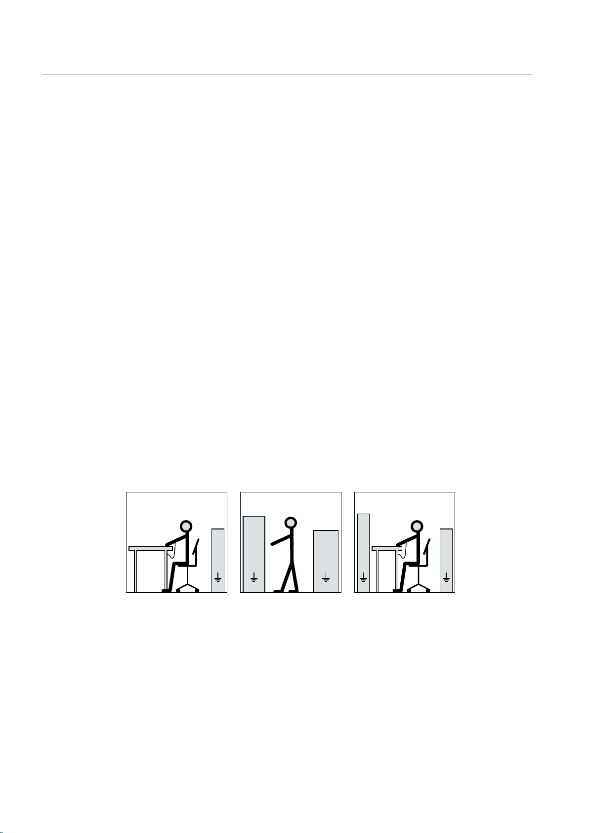
The necessary ESD protective measures for electrostatic sensitive devices are illustrated once
again in the following drawings:
a = conductive floor surfaceb = ESD table c = ESD shoes
d = ESD overall e = ESD wristband f = cabinet ground connection
2.6 Electromagnetic compatibility
This machine is designed in accordance with IEC/EN 60034, and when used as prescribed it
satisfies the requirements of European Directive 2014/30/EU on Electromagnetic Compatibility.
16 Operating Instructions 06/2018
SIMOTICS HV C 1NA14544WA600AG0-Z

Safety information
2.7 Interference immunity
2.7 Interference immunity
By selecting suitable signal cables and evaluation units, companies operating complete plants
and systems must ensure that the interference immunity of the machine is not diminished.
2.8 Influence on the line power supply through a strongly irregular torque
A strongly irregular torque, for example with the drive of a reciprocating motor, forces a nonsinusoidal motor current. The emerging harmonics can have an impermissible influence on
the line power supply via the connection lines.
2.9 Electromagnetic fields when operating electrical power engineering installations
Interference to electronic devices caused by electrical power equipment
Electrical power equipment generate electric fields during operation. Potentially lethal
malfunctions can occur in medical implants, e.g. pacemakers, in the vicinity of electrical power
equipment. Data may be lost on magnetic or electronic data carriers.
● It is forbidden for people with pacemakers to enter the vicinity of the machine.
● Protect the personnel working in the plant by taking appropriate measures, such as erecting
identifying markings, safety barriers and warning signs and giving safety talks.
● Observe the nationally applicable health and safety regulations.
● Do not carry any magnetic or electronic data media.
SIMOTICS HV C 1NA14544WA600AG0-Z
Operating Instructions 06/2018 17

Safety information
2.9 Electromagnetic fields when operating electrical power engineering installations
SIMOTICS HV C 1NA14544WA600AG0-Z
18 Operating Instructions 06/2018
Description
Applications
3
This electrical machine is designed for driving rotating machines in industrial environments
and also for energy conversion. It is characterized by a high level of safety, long lifetime, and
overall reliability.
For details of the machine supplied and the permissible operating conditions, refer to the
"Technical data and drawings" (Page 101) section in the Appendix of these Operating
Instructions.
The machine was designed in accordance with the ordering party's specification and may only
be used for the contractually agreed purpose.
WARNING
Risk of explosion
This machine is not designed for use in hazardous areas. An explosion can occur if the
machine is operated in these areas. This can result in death, serious injury or material damage.
● Never operate this machine in hazardous areas.
Machine design
The regulations and standards used as the basis to design and test this machine are stamped
on the rating plate.
The machine design basically complies with the subsequent standards. Please refer to the EU
Declaration of Conformity for the versions of the harmonized standards referenced.
Table 3-1 Machine design
Feature Standard
Rating and performance IEC/EN 60034‑1
Degree of protection IEC/EN 60034‑5
Cooling IEC/EN 60034‑6
Type of construction IEC/EN 60034‑7
Terminal markings and direction of rotation IEC/EN 60034‑8
Noise emission IEC/EN 60034‑9
Starting characteristics, rotating electrical machines IEC/EN 60034‑12*
Vibration severity grades IEC/EN 60034‑14
Vibration limits DIN ISO 10816-3
* For machines in line operation only
SIMOTICS HV C 1NA14544WA600AG0-Z
Operating Instructions 06/2018 19

Description
See also
Rating plate
Line operation
Cooling
Quality documents (Page 103)
The rating plate shows the identification data and the most important technical data. The data
on the rating plate and the contractual agreements define the limits of proper usage.
The motor is supplied from the line system.
If you connect the machine to a converter, the machine can be damaged. Operate the machine
only on the electrical supply system.
The cooling system is designed as a closed, internal cooling circuit. The machine power loss
is dissipated partially via heat conduction and partially via the cooling air at the cooling water
flowing through the water jacket. A shaft-mounted fan ensures circulation of the cooling air.
Rotor
The rotor is designed as a squirrel-cage rotor. The number and design of the shaft extensions
are shown and described in the technical data.
Supplementary devices
Temperature sensors are integrated in the stator winding to monitor the winding temperature.
Various supplementary devices can be integrated or mounted, depending on the order. These
include, for example, anti-condensation heating to prevent condensation or temperature
sensors for monitoring bearings.
Paint finish
The machine is painted according to the instructions in your order.
SIMOTICS HV C 1NA14544WA600AG0-Z
20 Operating Instructions 06/2018

Preparations for use
Good planning and preparation of machine applications are essential in terms of keeping
installation simple and avoiding errors, ensuring safe operation, and allowing access to the
machine for servicing and corrective maintenance.
This chapter outlines what you need to consider when configuring your plant in relation to this
machine and the preparations you need to make before the machine is delivered.
4.1 Safety-related aspects to consider when configuring the plant
A number of residual risks are associated with the machine. These are described in the chapter
titled "Safety information" (Page 13) and in related sections.
Take appropriate safety precautions (covers, barriers, markings, etc.) to ensure the machine
is operated safely within your plant.
4.2 Observing the operating mode
Observe the machine's operating mode. Use a suitable control system to prevent overspeeds,
thus protecting the machine from damage.
4
4.3 Cooling water quality
● The cooling water must circulate in a closed cooling circuit.
● Avoid fluctuations in the oxygen content of the cooling water.
● The cooling system is maintenance-free provided cooling water of the specified quality is
used.
Note
Order-specific agreements
Observe any order-specific agreements regarding the cooling water specification. These
might deviate from the named cooling water specification.
Cooling water specification
Characteristic Specified as Measured value German unitary proce‐
dure
pH 7.5 - 10 DIN 38404-5 (Z) ISO 10523
Conductivity <600 µS/cm DIN 38404-8 (Z) ISO 7888
Currently
ISO / alterna‐
tive
SIMOTICS HV C 1NA14544WA600AG0-Z
Operating Instructions 06/2018 21

Preparations for use
4.4 Noise emission
Chloride Cl <150 mg/l DIN 38405-1 ISO 9297
Manganese Mn <0.05 mg/l DIN 38406-2 ISO 6333 /
ISO 11885
Fluoride F <0.05 mg/l DIN 38405-4 ISO 10359-1
Sulfate SO
Copper Cu = Total copper <0.1 mg/l DIN 38406-7 ISO 8288 /
Silicic acid SiO
Free carbon dioxide CO
Total salts <1000 mg/l DIN 38409-1 Nitrate NO
Suspended matter <10 mg/l DIN 38409-2 ISO 11923
Permanganate consump‐
tion
Total hardness Mg+Ca <12 °DH DIN 38409-6 ISO 6059
Carbonate hardness HCO
Ammonium content N ISO 11732 /
Iron content Fe = Total iron <0.2 mg/l DIN 38406-1 ISO 6332 /
2-
4
<150 mg/l DIN 38405-5 ISO 10304
ISO 11885
2
2
-
3
<25 mg/l F1 (DIN 38407-1) ISO 16264
0 mg/l G1 (DIN 38408-1) -
<20 mg/l DIN 38405-9 ISO 7890-1
(Z) /
ISO 10304
O <12 mg/l H4 (DIN 38409-5) ISO 8467
-
3
<12 °DH DIN 38404-10 ISO 9963-1
<10 mg/l DIN 38406-5 ISO 11732 /
NH
+
4
ISO 14911
ISO 14911
ISO 11885
4.4 Noise emission
Excessive sound pressure levels can lead to hearing impairment or hearing loss.
● When assessing the noise level of the system, make due allowance for the noise emissions
from the machine.
● If necessary, take suitable noise protection measures for personnel.
4.5 Voltage and frequency fluctuations during line operation
Unless stated otherwise on the rating plate, the permissible voltage fluctuation is ±10 % and
the permissible frequency fluctuation is ±2 % in accordance with range B in IEC / EN 60034-1.
Permissible fluctuations that go beyond this are stamped on the rating plate.
SIMOTICS HV C 1NA14544WA600AG0-Z
22 Operating Instructions 06/2018

4.6 Phase synchronization during supply system switching
Under operating conditions a machine may sometimes have to be operated outside the limits
of range A.
● Exceeding the permissible tolerances for voltage and frequency can lead to an
impermissibly high temperature rise of the winding. This can result in long-term damage to
the machine.
● Limit exceptions of this sort with regard to the values that arise, how often, and for how long
they occur.
● Where possible and within a reasonable time take corrective actions such as reducing the
power. In this way you can avoid that the service life of the machine is reduced as a result
of thermal aging.
4.6 Phase synchronization during supply system switching
Damage to the machine may be caused when switching to another supply system with different
phasing.
● The phasing must be synchronized during switching. Use appropriate means to
synchronize the phasing.
Preparations for use
4.7 System-inherent frequencies
Excessively high vibration levels and system resonances can damage the machine set.
● Configure and match the system consisting of the foundation and machine set in such a
way that no system resonances can arise and result in the permissible vibration levels being
exceeded.
● The vibration values according to DIN ISO 10816-3 must not be exceeded.
4.8 Torsional loading of the drive train due to faults in the electrical supply
In the event of faults in the electrical connection, such as line switching operations with a
residual field or short circuit at the terminals, excessive air gap torques can occur. These
excessive air gap torques can lead to additional mechanical torsional loads on the shaft
assembly.
If the configuration does not correctly recognize the mechanical torsional loadings of the shaft
assembly, this can lead to serious damage to the machine. This can result in death, serious
injury or material damage.
● When planning the system, make due allowance for the maximum air gap torques that can
occur. This data can be found in the "Electrical data".
The system planner is responsible for the entire drive train.
SIMOTICS HV C 1NA14544WA600AG0-Z
Operating Instructions 06/2018 23
Preparations for use
4.9 Switching high-voltage motors
4.9 Switching high-voltage motors
If vacuum circuit breakers and vacuum contactors are used, then what are known as multiple
restrikes can occur when the machine is switched off. This depends on various factors, such
as:
● Arc-extinguishing principle of the switch
● Machine size
● Length of the power supply cable
● System capacitance, etc.
A surge suppressor to ground is installed in the switchgear between the circuit breaker and
the cable termination for each of the three conductors. The level of protection for the machine
windings is sufficient when the limiter is correctly selected (machine rated voltage / response
voltage).
Example
This current limit corresponds to the following upper power limits, depending on the relationship
between the starting current IA and rated current IN and on the voltage dip (up to approximately
20%) while the machine is starting up:
Table 4-1 Power limits
Rated voltage V
3 kV 750 kW
6 kV 1500 kW
10 kV 2500 kW
See also
Prior to commissioning (Page 59)
4.10 Thermal protection
The machine is equipped with measuring equipment to directly monitor the motor temperature
to protect the machine against overheating during operation. Plan a corresponding circuit for
monitoring. More information is provided in Technical Data.
4.11 Transport and storage
Observe the following when carrying out any work on the machine:
N
Power limit
● Comply with the general safety instructions (Page 13)
● Comply with the applicable national and sector-specific regulations.
● When using the machine within the European Union, comply with the specifications laid
down in EN 50110‑1 regarding safe operation of electrical equipment.
SIMOTICS HV C 1NA14544WA600AG0-Z
24 Operating Instructions 06/2018
4.11.1 Transport markings
The packing differs depending on the transport type and size. If not otherwise contractually
agreed, the packaging corresponds to the packing guidelines for International Standards for
Phytosanitary Measures (ISPM).
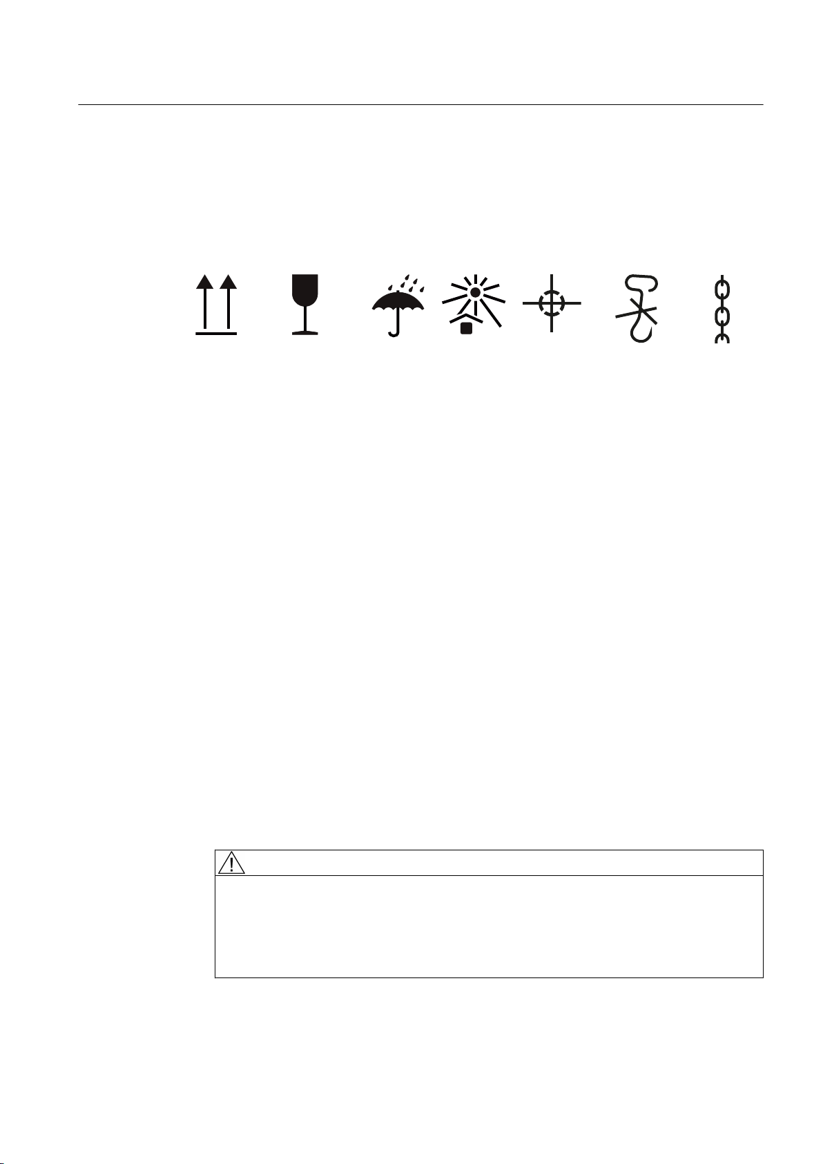
Note the symbols which appear on the packing. These have the following meanings:
Preparations for use
4.11 Transport and storage
Top Fragile material Keep dry Keep cool Center of
4.11.2 Checking the delivery
The components are assembled on an individual basis. When you take receipt of the delivery,
please check immediately whether the scope of the delivery matches up with the
accompanying documents. No claims relating to defects/items missing from the delivery will
be accepted if they are submitted at a later date.
● Report any apparent transport damage to the delivery agent immediately.
● Immediately report any apparent defects/missing components to your contact partner.
These Operating Instructions are part of the scope of delivery; keep them in a location where
they can be easily accessed.
4.11.3 Checking the load handling attachments
Inspect the load handling attachments such as the load trestles, lifting eyes and ring bolts and
also the lifting gear, before lifting the machine:
● Inspect the load handling attachments on the machine for possible damage. Replace any
load suspension equipment that is found to be damaged.
gravity
Do not use
hand hook
Attach here
● Before use, check that the load suspension equipment is correctly attached.
● When lifting the machine, use only approved and undamaged lifting gear of sufficient rated
capacity. Check the lifting gear prior to its use.
WARNING
The machine can be dropped
If the load handling attachments and lifting gear are damaged or not correctly secured,
the machine may be dropped during lifting. This can result in death, serious injury or
material damage.
● Inspect the load handling attachments and lifting gear before use.
SIMOTICS HV C 1NA14544WA600AG0-Z
Operating Instructions 06/2018 25

Preparations for use
4.11 Transport and storage
WARNING
Danger if the machine falls
The lifting lugs on the machine are designed only for the weight of the machine. If a machine
set is lifted and transported on a single machine, this can lead to mechanical failure of the
lifting lug. The machine or machine set may fall. This can result in death, serious injury or
material damage.
● Do not lift machine sets by attaching lifting tackle to the individual machines.
● Use only the equipment provided, e.g. the openings or lugs on the base plates, for
transporting machine sets. Note the maximum capacity of the lifting lug.
4.11.4 Lifting and transportation
● Persons driving cranes and fork-lift trucks must hold appropriate licenses.
● If the motor is packed, depending on the weight, size and on-site conditions, lift crates and
transport frames using a fork-lift truck or a crane with slings. Use a crane or fork-lift truck
suitable for the load.
● When lifting the machine, use only approved and undamaged sling guides and spreaders
of sufficient rated capacity. Check this equipment before using it. The weight of the machine
is shown on the rating plate.
● If adapter flange and adapter plates are also supplied, then lift them and transport these
parts separately. The load suspension equipment for the motor is not rated for lifting the
motor with mounted adapter flange is or adapter plates
SIMOTICS HV C 1NA14544WA600AG0-Z
26 Operating Instructions 06/2018
Preparations for use
4.11 Transport and storage
● When lifting the machine, refer to the information on the lifting plate or in the "Technical
Data and Drawings":
– Comply with the specified spreading angles.
– Do not exceed the maximum lifting acceleration and lifting speed specified on the lifting
plate. Lift the machine without jerking it.
Acceleration a ≤ 0.4 g (≈ 4 m/s2)
Velocity v ≤ 20 m/min
● Use only the attachment points provided on the stator frame for lifting, such as lifting eyes
or ring bolts or the lifting eyebolts on the bearing shield.
WARNING
Transport for a different type of construction
The machine or the machine set may be lifted and transported only using the load handling
attachments at the intended positions. Otherwise, the machine may tip over, slip in the
direction of lifting or fall.
This can result in death, serious injury or material damage.
1. Use only the attachment points (eyebolts, etc.) on the stator frame.
2. Use suitable rope guiding or spreading devices. You will find the weight of the motor
on the rating plate.
WARNING
Center of gravity is not at the center.
If the center of gravity of a load is not located centrally between the attachment points,
the motor can tip over or slip out of the lifting equipment and fall when it is being transported
or lifted. This can result in death, serious injury or material damage.
1. Always take account of the center of gravity when transporting or lifting the motor. The
center of gravity of the machine is specified in the dimension drawing.
2. Comply with the handling instructions on the machine when transporting it. If the center
of gravity is not located centrally between the attachment points, position the hoisting
hook above the center of gravity.
3. Be aware of the possibility of different loads on the sling ropes or lifting straps and the
carrying capacity of the lifting equipment.
NOTICE
Risk of corrosion and reduction of the degree of protection
Empty holes can corrode; the degree of protection may then be no longer guaranteed.
● Do not remove the factory-fitted load suspension device. In operation, the loadsuspension device must remain screwed in.
● If you do remove the load-suspension device, then seal the holes so that they are
airtight.
SIMOTICS HV C 1NA14544WA600AG0-Z
Operating Instructions 06/2018 27

Preparations for use
4.11 Transport and storage
WARNING
Lifting equipment can break at low temperatures
At low temperatures, the material of the lifting equipment can become brittle. When lifting and
transporting, the lifting equipment can tear off and the motor might be dropped.
This can result in death, serious injury, or material damage.
● Only lift the machine using the lifting equipment at temperatures that are not below -20 °C.
● Alternatively, warm up the lifting equipment or lift the machine in a different way.
4.11.5 Working on the underside of the machine
● Never remain under or in the immediate vicinity of the machine when it is lifted. If the lifting
gear or load handling attachments were to fail, the machine could fall. This can result in
death, serious injury or material damage.
● In order to gain easy and safe access to the underside of the machine, place it in a secure
and raised position.
4.11.6 Storage
You must correctly store the machine if you do not install and use it after it has been delivered.
NOTICE
Bearing seizure damage if incorrectly stored
If storage conditions are inappropriate there is a risk of bearing seizure damage. Resulting
damage can include scoring (brinelling) and corrosion.
● Follow the storage guidelines.
Preconditions and preparations
● Only store goods in undamaged packaging. Unpack the goods if the packaging is damaged.
Correctly store the goods corresponding to the type.
● Repair any damage to the packaging before putting the equipment into storage insofar as
this is necessary to ensure proper storage conditions.
SIMOTICS HV C 1NA14544WA600AG0-Z
28 Operating Instructions 06/2018

General instructions for storage
Wherever possible, store the machine in a storage room. The place of storage must satisfy
the following general conditions:
● Select a sufficiently sized dry and horizontal place of storage that is above flood level and
free of vibration (v
– The place of storage must be well ventilated as well as free of dust and frost. Provide
protection against extreme weather conditions. Ensure that the temperature remains
stable in the range from 10 °C to 50 °C – or 50 °F to 120 °F. If there is a risk of
condensation, the room temperature should be approx. 10 K above the outside
temperature. The temperature should not fall below ‑20° C.
– The relative humidity of the air should be less than 60%.
– The floor of the place of storage must be sufficiently strong. The maximum permissible
floor loading or storage compartment loading may not be exceeded.
– The ambient air must not contain any harmful gases.
● Protect the machine from shocks and humidity.
● Position machines, devices and crates on pallets, wooden beams or foundations that
protect them against rising damp and water.
≤ 0.2 mm/s).
eff
Preparations for use
4.11 Transport and storage
● Ensure that the air circulation under the equipment is not impeded.
– Place wooden spacer blocks between the covers and the machine.
– Covers or tarpaulins must not trail on the floor around the machine.
Storing outdoors
When storing the machines outside, the storage location must comply with the following
conditions:
● The ground must be sufficiently strong. Prevent the machine from sinking into the ground.
● Covers or tarpaulins used to protect the equipment against the weather must not make
contact with the surfaces of the equipment. Otherwise air circulation under the stored items
will be prevented.
Protection against humidity
If a dry storage space is not available, protect the machine as follows against humidity:
● Wrap the machine in humidity-absorbent material.
● Wrap the machine in plastic film:
– Place a humidity meter inside the plastic film.
– Place desiccant within the plastic film.
– Pack the machine air-tight.
● Inspect the machine regularly.
SIMOTICS HV C 1NA14544WA600AG0-Z
Operating Instructions 06/2018 29

Preparations for use
4.11 Transport and storage
Long-term storage
If you are storing a machine for more than six months, you must check its condition every six
months. Store the machine in accordance with the specifications in Section "Storage
(Page 28)", and if possible, packed.
● Check the motor for damage.
● Carry out any necessary maintenance work.
● Make sure that the storage conditions are such that condensation cannot form in the motor.
● If the machine is not sealed in plastic film, continually and slightly heat the machine, e.g.
with anti-condensation heating (if available), and ensure that the air circulates in the storage
room.
Storage for longer than three months
Lubricate the machine after every two years of storage.
1. Unpack the machine.
2. Remove the rotor shipping brace, if one is fitted.
3. When stored for longer than two years, lubricate with twice the grease quantity in
accordance with the lubricant plate. This ensures that the grease is evenly distributed and
covers all surfaces. Corrosion damage is avoided.
NOTICE
Rolling bearing damage due to unchanged resting position
Roller bearings can be damaged when kept in the same or almost the same position.
● Every three months, manually rotate the rotor through five revolutions.
● Make sure that the resting position of the rotor after the rotor has been turned over is
different from its previous position. Use the feather key as a reference point, if present.
4. Replace the corrosion protection.
5. Reattach the rotor shipping brace, if present.
6. Pack the machine again.
SIMOTICS HV C 1NA14544WA600AG0-Z
30 Operating Instructions 06/2018
 Loading...