

Siemens SIMOTICS FD 1MH1,SIMOTICS FD 1MQ1,SIMOTICS FD 1LL1 Operating Instructions & Installation Instructions

www.siemens.com/drives
For employment in zone 2 (IEC/EN 60079-10-1)
Operating Instructions
Installation Instructions
Low-voltage motor
SIMOTICS FD
Type 1MH1
II 3G Ex ec IIC T3 Gc
Edition 08/2017

18.08.2017 17:24
V10.00
Low-voltage motor
SIMOTICS FD
Type 1MH1
For employment in zone 2 (IEC/EN 60079-10-1)
II 3G Ex ec IIC T3 Gc
Introduction
1
Operating Instructions
Installation Instructions
Safety information
Description
Preparations for use
Assembly
Electrical connection
Start-up
Operation
2
3
4
5
6
7
8
Maintenance
Spare parts
Disposal
Service and Support
Technical data and drawings
Quality documents
9
10
11
A
B
C
Edition 08/2017

Legal information
Warning notice system
This manual contains notices you have to observe in order to ensure your personal safety, as well as to prevent
damage to property. The notices referring to your personal safety are highlighted in the manual by a safety alert
symbol, notices referring only to property damage have no safety alert symbol. These notices shown below are
graded according to the degree of danger.
DANGER
indicates that death or severe personal injury will result if proper precautions are not taken.
WARNING
indicates that death or severe personal injury may result if proper precautions are not taken.
CAUTION
indicates that minor personal injury can result if proper precautions are not taken.
NOTICE
indicates that property damage can result if proper precautions are not taken.
If more than one degree of danger is present, the warning notice representing the highest degree of danger will be
used. A notice warning of injury to persons with a safety alert symbol may also include a warning relating to property
damage.
Qualified Personnel
The product/system described in this documentation may be operated only by personnel qualified for the specific
task in accordance with the relevant documentation, in particular its warning notices and safety instructions. Qualified
personnel are those who, based on their training and experience, are capable of identifying risks and avoiding
potential hazards when working with these products/systems.
Proper use of Siemens products
Note the following:
WARNING
Siemens products may only be used for the applications described in the catalog and in the relevant technical
documentation. If products and components from other manufacturers are used, these must be recommended or
approved by Siemens. Proper transport, storage, installation, assembly, commissioning, operation and
maintenance are required to ensure that the products operate safely and without any problems. The permissible
ambient conditions must be complied with. The information in the relevant documentation must be observed.
Trademarks
All names identified by ® are registered trademarks of Siemens AG. The remaining trademarks in this publication
may be trademarks whose use by third parties for their own purposes could violate the rights of the owner.
Disclaimer of Liability
We have reviewed the contents of this publication to ensure consistency with the hardware and software described.
Since variance cannot be precluded entirely, we cannot guarantee full consistency. However, the information in
this publication is reviewed regularly and any necessary corrections are included in subsequent editions.
Siemens AG
Process Industries and Drives
Postfach 48 48
90026 NÜRNBERG
GERMANY
Document order number: A5E32582260
Ⓟ 08/2017 Subject to change
Copyright © Siemens AG 2017.
All rights reserved

Table of contents
1 Introduction.................................................................................................................................................13
1.1 About these instructions.........................................................................................................13
1.2 Compiling personal documents..............................................................................................13
2 Safety information.......................................................................................................................................15
2.1 Information for the nominated person in control of the electrical installation.........................15
2.2 The five safety rules...............................................................................................................16
2.3 Qualified personnel................................................................................................................16
2.4 Safe handling.........................................................................................................................16
2.5 For use in hazardous Zone 2 or Zone 22...............................................................................18
2.6 Electrostatic sensitive devices...............................................................................................19
2.7 Processes that generate high levels of electrostatic charge..................................................20
2.8 Interference immunity.............................................................................................................21
2.9 Influence on the line power supply through a strongly irregular torque..................................21
2.10 Interference voltages when operating the converter..............................................................21
2.11 Electromagnetic fields when operating electrical power engineering installations.................21
3 Description..................................................................................................................................................23
3.1 Comparison of IEC and GOST standards..............................................................................24
4 Preparations for use...................................................................................................................................33
4.1 Safety-related aspects to consider when configuring the plant..............................................33
4.2 Observing the operating mode...............................................................................................33
4.3 Ensuring cooling.....................................................................................................................33
4.4 Configuration of the cooling circuit and coolant supply..........................................................33
4.4.1 Material selection for the cooling circuit.................................................................................33
4.4.2 Pressures and differential pressures in the cooling circuit.....................................................34
4.4.3 Components and materials of the cooling circuit...................................................................35
4.4.4 Potential equalization on the cooling circuit components.......................................................35
4.4.5 Power loss..............................................................................................................................36
4.5 Coolant specification..............................................................................................................36
4.5.1 General coolant requirements................................................................................................36
4.5.2 Coolant specification (M85 "stainless steel version" option)..................................................38
4.5.3 Inhibitors, anti-freeze, biocides..............................................................................................39
4.5.4 Cooling capacity derating.......................................................................................................40
4.6 Thermal motor protection.......................................................................................................41
4.7 Thermal motor protection using PTC thermistors (option).....................................................41
SIMOTICS FD 1MH1
Operating Instructions 08/2017 5

Table of contents
4.8 Interlock circuit for the automatic regreasing system (option)................................................41
4.9 Interlock circuit for anti-condensation heating........................................................................41
4.10 Support base for IM B5 construction type..............................................................................42
4.11 Noise emissions.....................................................................................................................42
4.12 Rotational speed limit values.................................................................................................42
4.13 Complying with speed-torque curve.......................................................................................43
4.14 Voltage and frequency fluctuations during line operation......................................................43
4.15 Phase synchronization during supply system switching........................................................43
4.16 System-inherent frequencies.................................................................................................44
4.17 Torsional load of the drive train..............................................................................................44
4.18 Transport and storage............................................................................................................44
4.18.1 Checking the delivery.............................................................................................................45
4.18.2 Lifting and transportation........................................................................................................45
4.18.3 Securing the rotor...................................................................................................................46
4.18.4 Transporting the machine set.................................................................................................48
4.18.5 Storage...................................................................................................................................48
4.18.6 Protecting the cooling water circuit during storage................................................................51
4.18.7 Protection against corrosion...................................................................................................51
4.19 Converter operation...............................................................................................................52
4.19.1 Converter operation of explosion-proof machines.................................................................52
4.19.2 Supply line configuration........................................................................................................52
4.19.3 Converter input voltage..........................................................................................................53
4.19.4 Reducing bearing currents.....................................................................................................53
4.19.5 Insulated bearings when operating the converter..................................................................55
4.19.6 Converter operation on a grounded network..........................................................................57
5 Assembly....................................................................................................................................................59
5.1 Preparations for installation....................................................................................................60
5.1.1 Requirements for installation..................................................................................................60
5.1.2 Insulation resistance and polarization index..........................................................................60
5.1.3 Testing the insulation resistance and polarization index........................................................61
5.1.4 Prepare the mating faces (IM B3)..........................................................................................63
5.1.5 Prepare the mating face for a flange connection...................................................................64
5.1.6 Prepare the mating face for wall mounting ............................................................................64
5.2 Lift the machine to where it will be installed, and position it...................................................64
5.2.1 Preconditions for correct alignment and secure attachment .................................................64
5.2.2 Checking the load handling attachments...............................................................................65
5.2.3 Removing the rotor shipping brace........................................................................................65
5.2.4 Removing the rotor shipping brace from machines in vertical type........................................65
5.2.5 Removing anti-corrosion protection.......................................................................................66
5.2.6 Mounting the output elements................................................................................................66
5.2.7 Lifting and transportation........................................................................................................68
5.2.8 Putting the machine down......................................................................................................69
5.2.9 Draining condensation...........................................................................................................70
5.2.10 Roughly aligning the machine................................................................................................71
SIMOTICS FD 1MH1
6 Operating Instructions 08/2017

Table of contents
5.3 Installing the machine............................................................................................................72
5.3.1 Safety instructions for installation...........................................................................................72
5.3.2 Preconditions for smooth, vibration-free operation................................................................72
5.3.3 Aligning the machine to the driven machine and mounting (IM B3 / IM B35)........................73
5.3.4 Aligning the machine to the driven machine and attaching it to it (IM B5).............................74
5.3.5 Aligning the machine to the driven machine and attaching it to it (IM V1, IM V10)................75
5.3.6 Axial and radial forces............................................................................................................76
5.4 Connecting the cooling water supply.....................................................................................77
6 Electrical connection...................................................................................................................................79
6.1 Safety instructions relating to the electrical connection.........................................................79
6.2 Basic rules..............................................................................................................................80
6.3 Terminal box..........................................................................................................................80
6.3.1 Terminal box 1XB1621...........................................................................................................81
6.3.2 Terminal box 1XB1631...........................................................................................................82
6.3.3 Terminal box 1XB7730...........................................................................................................83
6.3.4 Terminal box 1XB7731...........................................................................................................83
6.3.5 Terminal box 1XB7740...........................................................................................................84
6.3.6 Terminal box 1XB7750...........................................................................................................85
6.3.7 Rotating the terminal box.......................................................................................................85
6.3.8 Mounting/removing the terminal box......................................................................................88
6.4 Preparation.............................................................................................................................89
6.4.1 Terminal designation..............................................................................................................89
6.4.2 Selecting cables.....................................................................................................................89
6.4.3 Connecting the grounding conductor.....................................................................................89
6.4.4 Connect metal shield in the terminal box ..............................................................................90
6.4.5 Connection without terminal box............................................................................................91
6.4.6 Connecting the machine for a specific direction of rotation....................................................91
6.5 Inserting and routing the cables.............................................................................................92
6.5.1 Bringing cables into the terminal box 1XB... with sealing insert with break-off ring...............92
6.5.2 Bringing cables into the terminal box 1XB... with cable gland................................................93
6.5.3 Certified cable entries, thread adapters and sealing plugs....................................................94
6.5.4 Laying cables.........................................................................................................................94
6.5.5 Connecting cables with cable lugs.........................................................................................95
6.5.6 Connecting cables without cable lugs....................................................................................96
6.5.7 Use of aluminum conductors..................................................................................................98
6.5.8 Using single-stranded cables.................................................................................................99
6.5.9 Internal equipotential bonding................................................................................................99
6.5.10 Stepless mating face for the seal in the terminal box cover ..................................................99
6.5.11 Minimum air clearances.......................................................................................................100
6.5.12 Finishing connection work....................................................................................................100
6.6 Connecting the auxiliary circuits...........................................................................................101
6.6.1 Selecting cables...................................................................................................................101
6.6.2 Bringing cables into the auxiliary terminal box and routing them.........................................101
6.6.3 Intrinsically safe circuits for sensors or probes....................................................................102
6.6.4 Connect metal shield in the terminal box ............................................................................102
6.6.5 Connecting temperature monitoring for the stator winding..................................................102
6.6.6 Terminating the connection work (auxiliary circuit)..............................................................103
SIMOTICS FD 1MH1
Operating Instructions 08/2017 7

Table of contents
7 Start-up.....................................................................................................................................................105
7.1 Checks to be carried out prior to commissioning ................................................................105
7.2 Converter operation.............................................................................................................106
7.3 Measuring the insulation resistance before commissioning.................................................107
7.4 Greasing the roller bearings prior to commissioning............................................................108
7.5 Setting the automatic regreasing system.............................................................................109
7.6 Setpoint values for monitoring the bearing temperature......................................................109
7.7 Set values for monitoring the winding temperature..............................................................110
7.8 Test run................................................................................................................................110
7.9 Switching off.........................................................................................................................112
7.10 Setting the motor parameters at the converter.....................................................................112
7.10.1 Selecting the motor type and motor data in the STARTER program...................................113
7.10.2 Commissioning at the SINAMICS S/G converter using the AOP30.....................................116
7.10.3 Commissioning at the SINAMICS G120P inverter using the IOP........................................119
8 Operation..................................................................................................................................................121
8.1 Safety guidelines in operation..............................................................................................121
8.2 Operation in hazardous areas of Zone 2..............................................................................122
8.3 Switching on the machine....................................................................................................123
8.4 Switching off the anti-condensation heating.........................................................................124
8.5 Regreasing roller bearings...................................................................................................124
8.6 Stoppages............................................................................................................................124
8.6.1 Avoidance of frost and corrosion damage in the cooling system.........................................125
8.6.2 Avoidance of condensation or formation of condensation within the machine.....................125
8.6.3 Avoidance of damage to roller bearings during stoppages..................................................126
8.6.4 Measurement of the insulation resistance after an extended stoppage...............................126
8.7 Decommissioning the machine............................................................................................127
8.8 Switching off the water-cooling system................................................................................127
8.9 Draining the coolant.............................................................................................................127
8.10 Re-commissioning the machine...........................................................................................128
8.11 Switching on again after an emergency switching-off..........................................................128
8.12 faults.....................................................................................................................................128
8.12.1 Inspections in the event of faults..........................................................................................128
8.12.2 Electrical faults.....................................................................................................................129
8.12.3 Mechanical faults.................................................................................................................129
8.12.4 Water cooling faults..............................................................................................................131
8.12.5 Roller bearing faults.............................................................................................................132
9 Maintenance.............................................................................................................................................133
9.1 Inspection and maintenance................................................................................................134
9.1.1 Safety instructions for inspection and maintenance.............................................................134
SIMOTICS FD 1MH1
8 Operating Instructions 08/2017

Table of contents
9.1.2 Measuring the insulation resistance during the course of maintenance work......................135
9.1.3 Inspections in the event of faults..........................................................................................136
9.1.4 First service after installation or repair.................................................................................136
9.1.5 General inspection...............................................................................................................137
9.1.6 Servicing and maintaining the anti-condensation heating....................................................137
9.1.7 Assessing the roller bearings...............................................................................................138
9.1.8 Roller bearings with automatic regreasing system...............................................................138
9.1.9 Regreasing intervals and types of grease for operating roller bearings...............................138
9.1.10 Sealing the rolling-contact bearings ("Increased degree of protection" option)...................142
9.1.11 Cleaning the cooling water ducts.........................................................................................143
9.1.12 Touch up any damaged paintwork.......................................................................................143
9.1.13 Repainting............................................................................................................................143
9.1.14 Maintaining terminal boxes..................................................................................................144
9.2 Corrective Maintenance.......................................................................................................145
9.2.1 Prepare servicing work.........................................................................................................145
9.2.2 Screws with preCOTE coating.............................................................................................147
9.2.3 Roller-contact bearings........................................................................................................147
9.2.3.1 Removing roller bearing.......................................................................................................147
9.2.3.2 Remove V ring.....................................................................................................................148
9.2.3.3 Removing the labyrinth sealing ring.....................................................................................148
9.2.3.4 Installing roller bearings.......................................................................................................149
9.2.3.5 Install the V ring...................................................................................................................150
9.2.3.6 Installing the V ring ("Increased degree of protection" option).............................................151
9.2.3.7 Installing the labyrinth sealing ring.......................................................................................152
9.2.4 Seal the motor......................................................................................................................153
10 Spare parts...............................................................................................................................................155
10.1 Ordering data.......................................................................................................................155
10.2 Ordering spare parts via the Internet...................................................................................155
10.3 Roller bearings.....................................................................................................................156
10.4 Anti-condensation heating....................................................................................................156
10.5 Housing, stators and rotors..................................................................................................157
10.6 Roller bearing cartridge at the drive and non-drive end.......................................................159
10.7 Roller bearing cartridge at the drive and non-drive end.......................................................160
10.8 Terminal box 1XB1621.........................................................................................................161
10.9 Terminal box 1XB1631.........................................................................................................163
10.10 Terminal box 1XB7730.........................................................................................................165
10.11 Terminal box 1XB7731.........................................................................................................166
10.12 Terminal box 1XB7740.........................................................................................................167
10.13 Terminal box 1XB7750.........................................................................................................168
10.14 Auxiliary terminal box 1XB9014...........................................................................................169
10.15 Auxiliary terminal box 1XB9015...........................................................................................170
10.16 1XB9016 auxiliary terminal box............................................................................................171
10.17 Auxiliary terminal box 1XB302.............................................................................................172
SIMOTICS FD 1MH1
Operating Instructions 08/2017 9

Table of contents
11 Disposal....................................................................................................................................................173
11.1 RoHS - restricting the use of certain hazardous substances...............................................173
11.2 Preparing for disassembly....................................................................................................173
11.3 Dismantling the machine......................................................................................................174
11.4 Disposal of components.......................................................................................................174
A Service and Support.................................................................................................................................177
B Technical data and drawings....................................................................................................................179
B.1 Tightening torques for screw and bolt connections..............................................................179
C Quality documents....................................................................................................................................181
Index.........................................................................................................................................................183
Tables
Table 3-1 Machine design ..........................................................................................................................23
Table 3-2 Machine design with type of protection Ex nA or Ex ec..............................................................24
Table 3-3 Data on the rating plate...............................................................................................................27
Table 3-4 Rolling-contact bearing variants..................................................................................................30
Table 4-1 Materials and components of a cooling circuit............................................................................35
Table 4-2 Substances that can destroy the cooling system........................................................................37
Table 4-3 Overview and application of coolant additives............................................................................39
Table 5-1 Stator winding insulation resistance at 40° C..............................................................................62
Table 5-2 Permissible deviations for aligning the machine with flexible coupling.......................................74
Table 6-1 Terminal designations using the 1U1-1 as an example..............................................................89
Table 6-2 Determining the cross-section of the grounding conductor.........................................................89
Table 6-3 Connection technology (with cable lug / connection without cable lug)......................................92
Table 6-4 Cable entry plate versions...........................................................................................................93
Table 6-5 Minimum air clearance dependent on rms value of the alternating voltage U
.......................100
rms
Table 7-1 Set values for monitoring the bearing temperatures before commissioning.............................109
Table 7-2 Set values for monitoring the bearing temperatures.................................................................109
Table 7-3 Set value for commissioning.....................................................................................................110
Table 7-4 Set values during normal operation...........................................................................................110
Table 8-1 Electrical faults .....................................................................................................................129
Table 8-2 Mechanical faults.......................................................................................................................129
Table 8-3 Cooling system faults ...........................................................................................................131
Table 8-4 Roller bearing faults .............................................................................................................132
Table 9-1 Checks after assembly or repair ...............................................................................................136
Table 9-2 Checks that have to be performed during the general inspection.............................................137
Table 9-3 Criteria for selecting roller bearing greases...............................................................................139
SIMOTICS FD 1MH1
10 Operating Instructions 08/2017

Table of contents
Table 9-4 Roller bearing greases for vertical and horizontal types of construction ..................................140
Table 9-5 Alternative greases with NLGI class 2 for motors of horizontal construction............................140
Table 10-1 Spare parts for housing, stators and rotors...............................................................................157
Table 10-2 Spare parts for the bearing cartridge at the drive end and non-drive end.................................159
Table 10-3 Spare parts for the bearing cartridge at the drive end and non-drive end.................................160
Table 10-4 Terminal box 1XB1621 spare parts...........................................................................................161
Table 10-5 Additional spare parts................................................................................................................162
Table 10-6 Additional spare parts for terminal box 1XB1631 with split cable entry.....................................164
Table 10-7 Main terminal box 1XB7730 spare parts...................................................................................165
Table 10-8 Additional spare parts................................................................................................................165
Table 10-9 Main terminal box 1XB7731 spare parts...................................................................................166
Table 10-10 Additional spare parts................................................................................................................166
Table 10-11 Main terminal box 1XB7740 spare parts...................................................................................167
Table 10-12 Additional spare parts................................................................................................................167
Table 10-13 Spare parts main terminal box 1XB7750...................................................................................168
Table B-1 Tightening torques for screw/bolt connections with a tolerance of ±10%.................................179
Figures
Figure 3-1 Schematic of the rating plate.......................................................................................................27
Figure 4-1 Axial fastening of the rotor...........................................................................................................47
Figure 4-2 Schematic representation of a single drive.................................................................................55
Figure 4-3 Schematic representation of a tandem drive...............................................................................56
Figure 5-1 Balancing type on the drive-end side..........................................................................................66
Figure 5-2 Condensation water drain for vertical mounting..........................................................................70
Figure 5-3 Condensation water drain for horizontal mounting......................................................................71
Figure 5-4 Schematic diagram: Aligning the machine to the driven machine...............................................73
Figure 5-5 Standard coolant connections and coolant drain hole................................................................77
Figure 6-1 Water drip loop............................................................................................................................80
Figure 6-2 Terminal box 1XB1621................................................................................................................81
Figure 6-3 Terminal box 1XB1631................................................................................................................82
Figure 6-4 Terminal box 1XB7730................................................................................................................83
Figure 6-5 Terminal box 1XB7731................................................................................................................83
Figure 6-6 Terminal box 1XB7740................................................................................................................84
Figure 6-7 Terminal box 1XB7750................................................................................................................85
Figure 6-8 Strain relief device and sealing insert..........................................................................................92
Figure 6-9 Connection with cable lug and fixing screw (schematic diagram)...............................................95
Figure 6-10 Connection using terminal clamps (schematic diagram).............................................................97
Figure 7-1 Selecting a motor type...............................................................................................................114
SIMOTICS FD 1MH1
Operating Instructions 08/2017 11

Table of contents
Figure 7-2 Entering the motor data.............................................................................................................115
Figure 9-1 Remove the V ring.....................................................................................................................148
Figure 9-2 Disassembling the labyrinth sealing ring (schematic diagram).................................................149
Figure 9-3 Install the V ring.........................................................................................................................151
Figure 9-4 Roller-contact bearing with grease chamber (schematic diagram)...........................................152
Figure 9-5 Position the set screws for the labyrinth sealing ring on the outer bearing cover.....................153
Figure 10-1 Housing, stators and rotors.......................................................................................................157
Figure 10-2 Bearing cartridge at the drive end and non-drive end...............................................................159
Figure 10-3 Bearing cartridge at the drive end and non-drive end...............................................................160
Figure 10-4 Terminal box 1XB1621 with standard cable entry.....................................................................161
Figure 10-5 Two-part cable entry..................................................................................................................161
Figure 10-6 Terminal box 1XB1631..............................................................................................................163
Figure 10-7 Main terminal box 1XB7730......................................................................................................165
Figure 10-8 Main terminal box 1XB7731......................................................................................................166
Figure 10-9 Main terminal box 1XB7740......................................................................................................167
Figure 10-10 Main terminal box 1XB7750 with standard cable entry.............................................................168
Figure 10-11 Auxiliary terminal box 1XB9014 .............................................................................................169
Figure 10-12 Auxiliary terminal box 1XB9015 .............................................................................................170
Figure 10-13 1XB9016 auxiliary terminal box ...............................................................................................171
Figure 10-14 Auxiliary terminal box 1XB302..................................................................................................172
SIMOTICS FD 1MH1
12 Operating Instructions 08/2017

Introduction
1.1 About these instructions
These instructions describe the machine and explain how to handle it, from initial delivery to
final disposal of the equipment. Keep these instructions for later use.
Read these operating instructions before you handle the machine and follow the instructions
to become familiar with its design and operating principles and thus ensure safe, problem-free
machine operation and long service life.
Please contact the Service Center (Page 177) if you have any suggestions on how to improve
this document.
Text format features
The warning notice system is explained on the rear of the inside front. Always follow the safety
instructions and notices in these instructions.
In addition to the safety-related warning notices which you must read, you will find the text in
these instructions is formatted in the following way:
1. Handling instructions are always formatted as a numbered list. Always perform the steps
in the order given.
1
● Lists are formatted as bulleted lists.
– Lists on the second level are hyphenated.
Note
A Note is an important item of information about the product, handling of the product or the
relevant section of the document. Notes provide you with help or further suggestions/ideas.
1.2 Compiling personal documents
On the Internet pages in Industry Online Support you have the possibility of compiling personal
documents using the function Documentation (
en/documentation)
Using the "Documentation" function, from Product Support manuals, you can compile your
own "Documentation". However, you can also include other Product Support content such as
FAQs or characteristics in the documentation that you compile.
In the "Documentation" function, you have the option of creating your own compiled documents
in your own structure and managing them. You can delete or shift individual chapters or topics.
Further, using the note function you can import your own content. The compiled
"documentation" can be exported as PDF, for example.
https://support.industry.siemens.com/My/ww/
SIMOTICS FD 1MH1
Operating Instructions 08/2017 13

Introduction
1.2 Compiling personal documents
Using the "Documentation" function, you can efficiently compile your own plant or system
documentation. The "Documentation" compiled in a specific language can also be
automatically exported in one of the other available languages.
The full functionality is only available for registered users.
SIMOTICS FD 1MH1
14 Operating Instructions 08/2017

Safety information
2.1 Information for the nominated person in control of the electrical installation
This electric machine has been designed and built in accordance with the specifications
contained in Directive 2014/35/EU ("Low-Voltage Directive") and is intended for use in
industrial plants. Please observe the country-specific regulations when using the electric
machine outside the European Community. Follow the local and industry-specific safety and
setup regulations.
The persons responsible for the plant must ensure the following:
● Planning and configuration work and all work carried out on and with the machine is only
to be done by qualified personnel.
● The operating instructions must always be available for all work.
● The technical data as well as the specifications relating to the permissible installation,
connection, ambient and operating conditions are taken into account at all times.
● The specific setup and safety regulations as well as regulations on the use of personal
protective equipment are observed.
Note
2
Use the services and support provided by the appropriate Service Center (Page 177) for
planning, installation, commissioning, and servicing work.
You will find safety instructions in the individual sections of this document. Follow the safety
instructions for your own safety, to protect other people and to avoid damage to property.
Observe the following safety instructions for all activities on and with the machine.
This machine has been designed and built in accordance with Directive 2014/34/EU
("Explosion Protection Directive") and is intended for use in industrial plants with potentially
explosive atmosphere.
Commissioning in the European Community in accordance with Directive 2006/42/EU
(“Machinery Directive”) is forbidden until the plant into which the machine will be installed has
been shown to conform with this directive. Please observe the country-specific regulations
when using the machine outside the European Community.
WARNING
Risk of explosion with commissioning prior to determining the conformity
If the machine is commissioned prior to determining the plant conformance, the explosion
protection of the plant is not ensured. An explosion can occur. This can result in death, serious
injury or material damage.
Do not commission the machine until it has been confirmed that the plant conforms with the
explosion protection directive.
SIMOTICS FD 1MH1
Operating Instructions 08/2017 15

Safety information
2.2 The five safety rules
2.2 The five safety rules
For your own personal safety and to prevent material damage when carrying out any work,
always observe the safety-relevant instructions and the following five safety rules according
to EN 50110‑1 "Working in a voltage-free state". Apply the five safety rules in the sequence
stated before starting work.
Five safety rules
1. Disconnect the system.
Also disconnect the auxiliary circuits, for example, anti-condensation heating.
2. Secure against reconnection.
3. Verify absence of operating voltage.
4. Ground and short-circuit.
5. Provide protection against adjacent live parts.
To energize the system, apply the measures in reverse order.
2.3 Qualified personnel
All work at the machine must be carried out by qualified personnel only. For the purpose of
this documentation, qualified personnel is taken to mean people who fulfill the following
requirements:
● Through appropriate training and experience, they are able to recognize and avoid risks
and potential dangers in their particular field of activity.
● They have been instructed to carry out work on the machine by the appropriate person
responsible.
2.4 Safe handling
Workplace safety depends on the attentiveness, care, and common sense of the personnel
who install, operate, and maintain the machine. In addition to the safety measures cited, as a
matter of principle, the use of caution is necessary when you are near the machine. Always
pay attention to your safety.
Also observe the following to prevent accidents:
● General safety regulations applicable in the country where the machine is deployed.
● Manufacturer-specific and application-specific regulations
● Special agreements made with the operator
● Separate safety instructions supplied with the machine
● Safety symbols and instructions on the machine and its packaging
SIMOTICS FD 1MH1
16 Operating Instructions 08/2017
Safety information
2.4 Safe handling
WARNING
Live parts
Electric machines contain live parts.
Fatal or severe injuries and substantial material damage can occur if the covers are removed
or if the machine is not handled, operated, or maintained properly.
● Always observe the “five safety rules" (Page 16) when carrying out any work on the
machine.
● Only remove the covers using the methods described by these operating instructions.
● Operate the machine properly.
● Regularly and professionally maintain the machine according to the instructions provided
in Chapter "Maintenance".
WARNING
Rotating parts
Electric machines contain dangerous rotating parts.
Fatal or severe injuries and substantial material damage can occur if the covers are removed
or if the machine is not handled, operated, or maintained properly.
● Only remove the covers using the methods described by these operating instructions.
● Operate the machine properly.
● Regularly and correctly maintain the machine.
● Secure free shaft extensions and other rotating part such as couplings and pulley belts
so that they cannot be touched.
WARNING
Hot surfaces
Electric machines have hot surfaces. Touching hot surfaces can result in severe burns.
● Allow the machine to cool before starting work on the machine.
● Only remove the covers using the methods described by these operating instructions.
● Operate the machine properly.
CAUTION
Hazardous substances
Chemical substances required for the setup, operation and maintenance of machines can
present a health risk.
Poisoning, skin damage, cauterization of the respiratory tract, and other health damage may
result.
● Read the information in these operating instructions and the product information supplied
by the manufacturer.
● Observe the relevant safety regulations and wear the personal protective equipment
specified.
SIMOTICS FD 1MH1
Operating Instructions 08/2017 17

Safety information
2.5 For use in hazardous Zone 2 or Zone 22
CAUTION
Flammable substances
Chemical substances required for the setup, operation and maintenance of machines may
be flammable.
Burns and other damage to health and material may result.
● Read the information in these operating instructions and the product information supplied
by the manufacturer.
● Observe the relevant safety regulations and wear the personal protective equipment
specified.
WARNING
Noise emissions
During operation, the machine's noise emission levels can exceed those permitted at the
workplace, which can cause hearing damage.
Take steps to reduce noise, such as introducing covers and protective insulation or adopting
hearing protection measures, so that the machine can be operated safely within your system.
2.5 For use in hazardous Zone 2 or Zone 22
Electrical systems in hazardous areas must be assembled, installed, and operated by the
applicable responsible persons in accordance with the applicable rules and regulations.
Note
The basic requirements relating to electrical systems and their operation in hazardous areas
are described, for instance, in EU Directive 1999/92/EC as well as in IEC / EN 60079-14.
Ignition hazards
The operating company – together with the responsible authorities – must fully evaluate the
operational risks, the local operating conditions and the monitoring methods that are required.
It is essential that the operating company complies with the necessary measures. Regarding
this topic, the machine manufacturer cannot provide any generally applicable
recommendations. Please observe the information in these operating instructions.
Note
The basic requirements relating to the assessment of ignition hazards arising from electrical
equipment and their operation in hazardous zones are specified, for instance, in directives
2014/34/EU (" Explosion protection directive") and 1999/92/EC - as well as in the
IEC / EN 60079 series of standards.
SIMOTICS FD 1MH1
18 Operating Instructions 08/2017
If a third-party certification is available for the machine, then carefully comply with the technical
6LW]SODW]
6WHKSODW]
6WHK6LW]SODW]
EE
D
F
D
IIIII
D
FF
H
GG
H
G
data defined in it and any special conditions.
The certificate must be available before commissioning.
2.6 Electrostatic sensitive devices
ESD protective measures
NOTICE
Electrostatic discharge
Electronic modules contain components that can be destroyed by electrostatic discharge.
These components can be damaged or destroyed if they are not handled correctly. To protect
equipment against damage, follow the instructions given below.
● Only touch electronic modules if you absolutely have to work on them.
● The body of the person concerned must have been electrostatically discharged and
grounded immediately before any electronic modules are touched.
● Electronic modules should not be brought into contact with electrically insulating materials,
such as:
– Plastic film
– Plastic parts
– Insulating table supports
– Clothing made of synthetic fibers
● Always place electrostatic sensitive devices on conductive bases.
● Always pack, store and transport electronic modules or components in conductive
packaging, such as:
– Metallized plastic or metal containers
– Conductive foam material
– Domestic aluminum foil
Safety information
2.6 Electrostatic sensitive devices
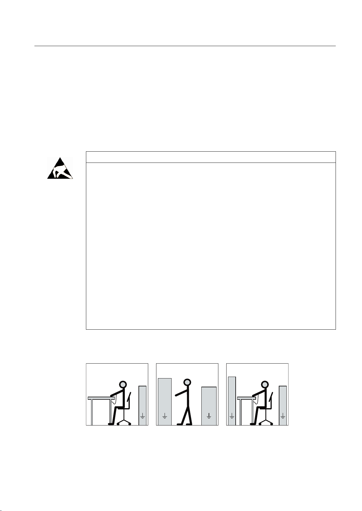
The necessary ESD protective measures for electrostatic sensitive devices are illustrated once
again in the following drawings:
a = conductive floor surfaceb = ESD table c = ESD shoes
d = ESD overall e = ESD wristband f = cabinet ground connection
SIMOTICS FD 1MH1
Operating Instructions 08/2017 19

Safety information
2.7 Processes that generate high levels of electrostatic charge
WARNING
Risk of explosion due to electrostatic discharge
Electrostatic discharge poses a potential ignition source. Dangerous electrostatic charges
can occur, for example as a result of mechanical friction, flowing air that contains particles or persons that are not appropriately grounded, e.g. when carrying out maintenance or
cleaning work.
In an explosive atmosphere, there is a risk of an explosion. This can result in death, serious
injury or material damage.
● Avoid carrying out work specified above on non-metallic parts, e.g. foam rubber for noise
dampeners/attenuators.
● Please comply with ESD protective measures.
2.7 Processes that generate high levels of electrostatic charge
Processes that generate high levels of electrostatic charge, which are far higher than those
generated through manual rubbing, include the following:
● Operation of high-voltage electrodes and ionizers
● Presence of high-speed particles on surfaces, e.g. sprayed charges (electron and ion flows)
in electrostatic coating processes
● Pneumatically conveyed dusts and bulk goods
● Flowing or hydraulically conveyed liquids and drops
● Belts, brushes and foils etc. moved by machines
WARNING
Risk of explosion as a result of processes with high levels of electrostatic charging
Processes with high levels of electrostatic charging can result in propagating brush discharge/
brushing discharge and explosion
This can result in death, serious injury or material damage.
● Avoid all of these processes in areas where there is risk of gas and dust explosions at
non-metallic exposed components, e.g. paint finishes. These discharge types are not
addressed in current standards.
● The non-metallic exposed components, e.g. paint finishes are subject to an electrostatic
suitability test in the factory. When supplied, the motor has its original paint finish.
Use the tested, original paint when repainting or touching up. It is possible to use a paint
that has not been tested by Siemens, which is however suitable from an electrostatic
perspective. The operating company is responsible for carrying out an electrostatic test
of the complete system.
SIMOTICS FD 1MH1
20 Operating Instructions 08/2017

Safety information
2.8 Interference immunity
2.8 Interference immunity
By selecting suitable signal cables and evaluation units, companies operating complete plants
and systems must ensure that the interference immunity of the machine is not diminished.
2.9 Influence on the line power supply through a strongly irregular torque
A strongly irregular torque, for example with the drive of a reciprocating motor, forces a nonsinusoidal motor current. The emerging harmonics can have an impermissible influence on
the line power supply via the connection lines.
2.10 Interference voltages when operating the converter
WARNING
Interference voltages when operating the converter
When a converter is in operation, the emitted interference varies in strength depending on
the converter (manufacturer, type, interference suppression measures undertaken). On
machines with integrated sensors (e.g. PTC thermistors), interference voltages caused by
the converter may occur on the sensor lead. This can cause faults which can result in eventual
or immediate death, serious injury or material damage.
● Comply with the EMC information provided by the manufacturer of the converter. This is
how you prevent the limit values stipulated by IEC/EN 61000-6-3 for the drive system
(consisting of the machine and converter) from being exceeded.
● You must put appropriate EMC measures in place.
2.11 Electromagnetic fields when operating electrical power engineering installations
WARNING
Interference to electronic devices caused by electrical power equipment
Electrical power equipment generate electric fields during operation. Potentially lethal
malfunctions can occur in medical implants, e.g. pacemakers, in the vicinity of electrical power
equipment. Data may be lost on magnetic or electronic data carriers.
● It is forbidden for people with pacemakers to enter the vicinity of the machine.
● Protect the personnel working in the plant by taking appropriate measures, such as
erecting identifying markings, safety barriers and warning signs and giving safety talks.
● Observe the nationally applicable health and safety regulations.
● Do not carry any magnetic or electronic data media.
SIMOTICS FD 1MH1
Operating Instructions 08/2017 21

Safety information
2.11 Electromagnetic fields when operating electrical power engineering installations
SIMOTICS FD 1MH1
22 Operating Instructions 08/2017

Description
Applications
This electrical machine has been designed for a wide range of drive and energy conversion
applications. The machines are characterized by extreme ruggedness, long service life, and
overall reliability. They are also highly versatile, allowing them to be tailored to specific
functions.
Details of the supplied machine and permissible operating conditions can be found in this
documentation.
The machine was designed in accordance with the ordering party's specification and may only
be used for the contractually agreed purpose. The permissible operating conditions are
specified on the rating plate. The technical data are described in the catalog.
Ex nA or Ex ec type of protection
This machine has Ex nA or Ex ec type of protection according to IEC / EN 60079-15 or -7. It
can therefore be operated in hazardous areas of Zone 2 according to IEC / EN 60079‑10-1.
3
Machine design
WARNING
Explosion hazard
This machine is not designed for use in areas at risk of dust explosion or in areas where an
explosion hazard exists due to hybrid mixtures. An explosion can occur if the machine is
operated in these areas. This can result in death, serious injury or material damage.
● Never operate this machine in the presence of explosive dust or in areas where an
explosion hazard exists due to hybrid mixtures.
The regulations and standards used as the basis to design and test this machine are stamped
on the rating plate.
The machine design basically complies with the subsequent standards. Please refer to the EU
Declaration of Conformity for the versions of the harmonized standards referenced.
Table 3-1 Machine design
Feature Standard
Rating and performance IEC/EN 60034‑1
Degree of protection IEC/EN 60034‑5
Cooling IEC/EN 60034‑6
Type of construction IEC/EN 60034‑7
SIMOTICS FD 1MH1
Operating Instructions 08/2017 23

Description
3.1 Comparison of IEC and GOST standards
Feature Standard
Terminal markings and direction of rotation IEC/EN 60034‑8
Noise emission IEC/EN 60034‑9
Starting characteristics of rotating electrical machines * IEC/EN 60034‑12
Vibration severity grades IEC/EN 60034‑14
Efficiency classification of three-phase squirrel-cage induction motors **IEC/EN 60034-30-1
Vibration limits DIN ISO 10816-3
* For machines in line operation only
** Exception: Pole-changing motors
See also
Quality documents (Page 181)
The following standards additionally apply for explosion-proof machines:
Table 3-2 Machine design with type of protection Ex nA or Ex ec
Feature Standard
Type of protection Ex nA or Ex ec
①
Optional (depending on order)
①
3.1 Comparison of IEC and GOST standards
Comparison of IEC and GOST standards
The IEC/EN standards correspond to the following GOST standards.
IEC/EN GOST
IEC/EN 60034-1 GOST R IEC 60034-1
IEC/EN 60034-5 GOST R IEC 60034-5
IEC/EN 60034-6 GOST R IEC 60034-6
IEC/EN 60034-7 GOST R IEC 60034-7
IEC/EN 60034-8 GOST R IEC 60034-8
IEC/EN 60034-9 GOST R IEC 60034-9
IEC/EN 60034-12 GOST R IEC 60034-12
IEC/EN 60034-14 GOST R IEC 60034-14
IEC/EN 60079‑0
IEC / EN 60079-15 or -7
This machine has been designed and built in accordance with Directive 2014/34/EU and
Customs Union Technical Regulation "On safety of equipment intended for use in explosive
atmospheres" (TR CU 012/2011) and is intended for use in industrial plants with potentially
explosive atmospheres.
SIMOTICS FD 1MH1
24 Operating Instructions 08/2017

3.1 Comparison of IEC and GOST standards
The IEC/EN standards correspond to the following GOST standards.
IEC/EN GOST
IEC/EN 60079-0 GOST R IEC 60079-0
IEC/EN 60079-2 GOST IEC 60079-2
IEC/EN 60079-7 GOST R IEC 60079-7
IEC/EN 60079-10 GOST IEC 60079-10
IEC/EN 60079-14 GOST IEC 60079-14
IEC/EN 60079-15 GOST R IEC 60079-15
Ex marking for type of protection Ex nA IIC T3 Gc or Ex ec IIC T3 Gc
Description
II 3 G Ex nA
ec
IIC T3 Gc
① ② ③ ④ ⑤ ⑥ ⑦ ⑧ ⑨ ⑩
AA87
2 Ex nA IIC T3 Gc X
① ⑪ ② ⑫ ⑥ ⑦ ⑧ ⑨ ⑩ ⑬
① CE- or EAC marking
② Code for prevention of explosions
③ Equipment group: II not for mining, but other hazardous zones
④ Device category: 3 for infrequent, short-term danger
⑤ Atmosphere: G for gas
⑥ Explosion protection: International
⑦ "nA" or "ec" type of protection
⑧ Explosion group: IIC for acetylene
⑨ Temperature Class: T3 for maximum surface temperature 200 °C
⑩ Device protection level: Gc for an extended level of protection in hazardous zones with
explosive gas mixtures
⑪ Identification number or name of nominated testing agency
⑫ Zone 2
⑬ "X" special conditions
Ex marking for type of protection Ex nA IIB T3 Gc or Ex ec IIB T3 Gc
II 3 G Ex nA
ec
IIB T3 Gc
① ② ③ ④ ⑤ ⑥ ⑦ ⑧ ⑨ ⑩
SIMOTICS FD 1MH1
Operating Instructions 08/2017 25

Description
3.1 Comparison of IEC and GOST standards
AA87
① ⑪ ② ⑫ ⑥ ⑦ ⑧ ⑨ ⑩ ⑬
① CE- or EAC marking
② Code for prevention of explosions
③ Equipment group: II not for mining, but other hazardous zones
④ Device category: 3 for infrequent, short-term danger
⑤ Atmosphere: G for gas
⑥ Explosion protection: International
⑦ "nA" or "ec" type of protection
⑧ Explosion group: IIB for ethylene
⑨ Temperature Class: T3 for maximum surface temperature 200 °C
⑩ Device protection level: Gc for an extended level of protection in hazardous zones with
explosive gas mixtures
⑪ Identification number or name of nominated testing agency
⑫ Zone 2
⑬ "X" special conditions
2 Ex nA IIB T3 Gc X
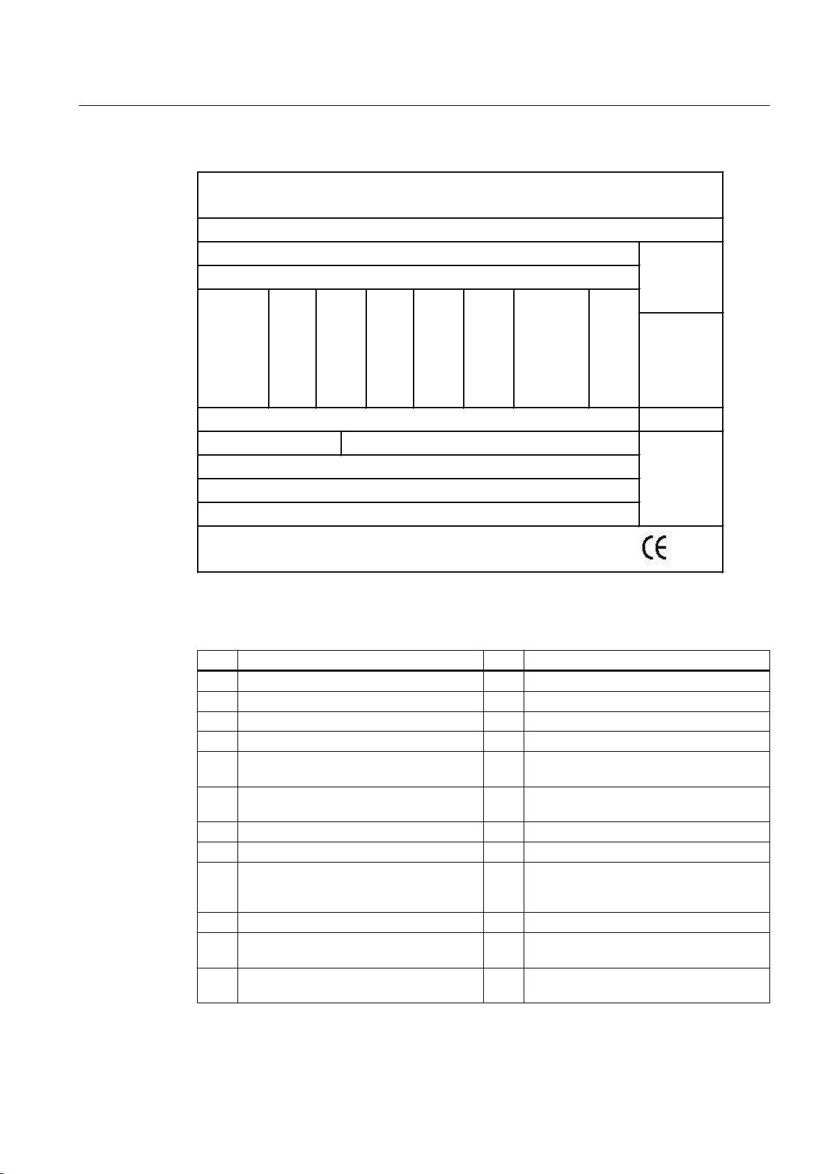
Rating plate
The rating plate shows the identification data and the most important technical data. The data
on the rating plate and the contractual agreements define the limits of proper usage.
SIMOTICS FD 1MH1
26 Operating Instructions 08/2017
'(:
RR
RR
SIEMENS
Description
3.1 Comparison of IEC and GOST standards
Figure 3-1 Schematic of the rating plate
Table 3-3 Data on the rating plate
Item Description Item Description
(1) Type of motor (15) Rated power [kW or HP]
(2) Order number (16) Rated efficiency factor
(3) Identifier of the motor series (17) Rated speed [rpm]
(4) Serial number (18) Rated frequency [Hz]
(5) Weight (19) Efficiency class (IE code) or efficiency ac‐
(6) Degree of protection (20) Efficiency according to IEC/EN 60034-2-1
(7) Type of construction (21) Motor design (converter or mains motor)
(8) Permissible ambient temperature range (22) Line voltage/frequency
(9) Thermal class of the insulation system (23) Optional additional data (e.g. service fac‐
(10) Thermal class of the utilization (24) Country of manufacture and location
(11) Maximum speed [rpm] (25) Certification mark for UL/CSA + file number
(12) Standards (26) Certificate number(s) for Ex motors for
cording to IEEE112B or empty
or current at service factor power
tor, design and code letter, amount of cool‐
ing water and intake temperature, etc.)
(optional)
Zone 2 (optional)
SIMOTICS FD 1MH1
Operating Instructions 08/2017 27

Description
3.1 Comparison of IEC and GOST standards
Item Description Item Description
(13) Rated voltage [V] and connections (27) Direction of rotation
(14) Rated current [A] (28) Data matrix code (order number and serial
Relevant directives
The following directives are relevant for the SIMOTICS motor series.
European low-voltage directive
The SIMOTICS motor series complies with the requirements of the low-voltage directive
2014/35/EU.
European machinery directive
The SIMOTICS motor series does not fall within the area of validity of the machinery directive.
However, the use of the products in a typical machine application has been fully assessed for
compliance with the main regulations in this directive concerning health and safety.
European EMC Directive
The SIMOTICS motor series does not fall within the area of validity of the EMC directive. The
products are not considered as devices in the sense of the directive.
number)
Eurasian conformity
The SIMOTICS motor series complies with the requirements of the Russia/Belarus/
Kazakhstan customs union (EAC).
China Compulsory Certification
The SIMOTICS motor series does not fall in the area of validity of the China Compulsory
Certification (CCC).
Underwriters Laboratories
The SIMOTICS motor series generally complies with UL and cUL requirements as component
of motor applications - and is correspondingly listed. Specifically developed motors and
functions are the exceptions in this case. Here, it is important that you carefully observe the
contents of the quotation and that there is a cUL mark on the rating plate (nameplate)!
Quality management system
Siemens AG employs a quality management system that meets the requirements of ISO 9001
and ISO 14001.
Certificates that can be downloaded
You can download certificates for the SIMOTICS motor series at the following link:
Certificates (https://support.industry.siemens.com/cs/ww/en/ps/13358/cert)
SIMOTICS FD 1MH1
28 Operating Instructions 08/2017

Rotors
Drive
Line operation
Description
3.1 Comparison of IEC and GOST standards
The rotor assembly is pressed onto the shaft together with the cage winding. The drive end of
the shaft usually has a cylindrical shaft end. Dependent on the design, a second shaft end
may be located at the non-drive end.
The motor speed is controlled using a converter. It has been optimized for operation with
SINAMICS low-voltage converters.
Other converters must comply with certain requirements: You can find more information in the
catalog or in the engineering documentation.
The motor is supplied from the line system.
NOTICE
Destruction of the machine when operated directly from the line supply
The machine will be destroyed if it is directly connected to the line supply. Only operate the
machine using a converter.
NOTICE
Machine damage for operation on the converter
If you connect the machine to a converter, the machine can be damaged. Operate the
machine only on the electrical supply system.
Cooling
The cooling system is designed as a closed, internal cooling circuit. The heat lost from the
machine is dissipated partially via heat conduction and partially via the cooling air at the cooling
water flowing through the cooling pipes. A shaft-mounted fan ensures circulation of the cooling
air.
Degree of protection
The machine is available with degree of protection IP55.
SIMOTICS FD 1MH1
Operating Instructions 08/2017 29

Description
3.1 Comparison of IEC and GOST standards
Rolling-contact bearings
The machines are equipped with different types of rolling-contact bearings depending on the
version and the operating conditions described in the order. The different types are listed on
the lubricant plate of the machine. In converter operation an insulated bearing is usually
installed on the non-drive end. The following rolling-contact bearing variants are available:
Table 3-4 Rolling-contact bearing variants
Version Rolling-contact bearing
Horizontal type of construction,
coupling output
Horizontal type of construction,
for increased transverse forces
e.g. in the case of belt coupling
Vertical type of construction,
shaft height 315, coupling output
Vertical type of construction,
shaft height 355 ... 450
● Drive end: Deep-groove ball bearing as a fixed bearing
● Non-drive end: Deep-groove ball bearing as a floating bearing
with axial compression springs
● Drive end: Cylindrical-roller bearing as a floating bearing
● Non-drive end: Deep-groove ball bearing as a fixed bearing
● Drive end: Deep-groove ball bearing as a fixed bearing
● Non-drive end: Deep-groove ball bearing as a floating bearing
with axial compression springs
● Drive end: Pairing of angular-contact ball bearing / deep-groove
ball bearing as a fixed bearing
● Non-drive end: Deep-groove ball bearing as a floating bearing
with axial compression springs
Automatic regreasing system (option)
The roller bearings are optionally equipped with an automatic regreasing system. The roller
bearings are supplied with new grease portions by the regreasing system in parameterized
time intervals.
Rolling-contact bearing design for "Increased degree of protection" (option)
Improved sealing of the bearing units to prevent dust and water from getting in can be achieved
by positioning a grease chamber ahead of the actual bearing unit. Although the same grease
is used in both cases for reasons of convenience, a distinction is made here between
"lubricating grease" and "sealing grease" because of their different functions.
Layout
The spent lubricating grease collects in the space between the bearing housing and the outer
bearing cap. The latter also forms the sealing grease chamber with the labyrinth sealing ring
(optional). The second lubricating nipple containing the grease duct for pressing in the sealing
grease is also located in the outer bearing cap. The chamber is sealed off from the space
where the lubricating grease collects by a V-ring or a V-ring and felt ring combination which
prevents the sealing grease in the chamber from penetrating into the lubricating grease
collecting space. During operation, the sealing grease in the chamber slowly runs out via the
labyrinth and seals it, additionally removing dust from inside and around the outside of the
labyrinth ring.
SIMOTICS FD 1MH1
30 Operating Instructions 08/2017
 Loading...