

Siemens SIMATIC TIM 3V-IE DNP3, SIMATIC TIM 4R-IE DNP3, TIM 3V-IE DNP3, TIM 4R-IE DNP3 System Manual

TIM DNP3
___________________
___________________
___________________
___________________
___________________
___________________
___________________
___________________
___________________
___________________
___________________
___________________
SIMATIC NET
Industrial Remote Communication Telecontrol
TIM DNP3
System Manual
TIM 3V-IE DNP3
TIM 4R
12/2015
C79000
Preface
Uses and properties of the
TIM
1
Network structures and
configurations
2
LEDs and connectors
3
Installation and
commissioning
4
Configuration in STEP 7
5
The SINAUT Configuration
Tool
6
Diagnostics and upkeep
7
Technical specifications
8
Approvals
9
Accessories
A
PG routing via WAN
B
-IE DNP3
-G8976-C253-04

Siemens AG
Division Process Industries and Drives
Postfach 48 48
9
GERMANY
C79000-G8976-C253-04
Ⓟ
Copyright © Siemens AG 2011 - 2015.
All rights reserved
Legal information
Warning notice system
DANGER
indicates that death or severe personal injury will result if proper precautions are not taken.
WARNING
indicates that death or severe personal injury may result if proper precautions are not taken.
CAUTION
indicates that minor personal injury can result if proper precautions are not taken.
NOTICE
indicates that property damage can result if proper precautions are not taken.
Qualified Personnel
personnel qualified
Proper use of Siemens products
WARNING
Siemens products may only be used for the applications described in the catalog and in the relevant technical
maintenance are required to ensure that the products operate safely and without any problems. The permissible
ambient conditions must be complied with. The information in the relevant documentation must be observed.
Trademarks
Disclaimer of Liability
This manual contains notices you have to observe in order to ensure your personal safety, as well as to prevent
damage to property. The notices referring to your personal safety are highlighted in the manual by a safety alert
symbol, notices referring only to property damage have no safety alert symbol. These notices shown below are
graded according to the degree of danger.
If more than one degree of danger is present, the warning notice representing the highest degree of danger will
be used. A notice warning of injury to persons with a safety alert symbol may also include a warning relating to
property damage.
The product/system described in this documentation may be operated only by
task in accordance with the relevant documentation, in particular its warning notices and safety instructions.
Qualified personnel are those who, based on their training and experience, are capable of identifying risks and
avoiding potential hazards when working with these products/systems.
Note the following:
documentation. If products and components from other manufacturers are used, these must be recommended
or approved by Siemens. Proper transport, storage, installation, assembly, commissioning, operation and
All names identified by ® are registered trademarks of Siemens AG. The remaining trademarks in this publication
may be trademarks whose use by third parties for their own purposes could violate the rights of the owner.
We have reviewed the contents of this publication to ensure consistency with the hardware and software
described. Since variance cannot be precluded entirely, we cannot guarantee full consistency. However, the
information in this publication is reviewed regularly and any necessary corrections are included in subsequent
editions.
for the specific
0026 NÜRNBERG
12/2015 Subject to change

Preface
Validity of this manual
TIM 3V-IE DNP3
TIM 4R-IE DNP3
Product names and abbreviations
TIM
DNP3 TIM
Purpose of the manual
This manual applies to the following modules:
●
Hardware product version: 4
Firmware version V3.1
Article number: 6NH7803-3BA00-0AA0
●
Hardware product version: 4
Firmware version V3.1
Article number: 6NH7803-4BA00-0AA0
Communications modules for the SIMATIC 300/400 for DNP3 communication via classic
WAN networks (via serial interface) and IP-based LAN / WAN networks (via RJ-45 interface)
The following short forms of product names are often used in this manual:
●
●
Simplified names of the two TIM modules named above if the property being described in the
particular context applies equally to both modules.
This manual supports you during the configuration, installation, commissioning and operation
of the DNP3 modules in a DNP3 network.
TIM DNP3
System Manual, 12/2015, C79000-G8976-C253-04
3

Preface
New in this release
Replaced documentation
Current manual release on the Internet
Compatibility with older firmware versions
Hardware and software requirements and compatibility
● New functions of the above firmware version of the TIM:
– New data object "DNP_Cmd01X_R" for the function of the DNP3 Object Group 12 /
Variation 1 in the station
– Expansion of the DNP3 station address range to 65519
– Expansion of the data objects “Dat12D_S / Dat12D_R“ with the data type DWORD
– Expansion of the data objects “Par12D_S / Par12D_R“ to all data types except BOOL
For information on the new and expanded data objects refer to Objects of TD7onTIM
(Page 177) and Data objects: Specific channel parameters (Page 206).
– Expansion of the Security functionality to protect against loading and deleting SDBs
(system data) of the TIM from a PG/PC
See section "Options" tab (Page 130) for information on this.
● Adaptation of the SINAUT engineering software for configuration of the new functions
● Editorial revision
This manual replaces the manual release 06/2014.
You will also find the current version of this manual on the Internet pages of Siemens
Industry Online Support under at the following address:
49109245 (https://support.industry.siemens.com/cs/ww/en/ps/15939/man)
46636298 (https://support.industry.siemens.com/cs/ww/en/ps/15940/man)
The DNP3 TIM with the firmware version described here is downward compatible with a
DNP3 TIM with firmware version 2.0.
The hardware components and software versions required for configuration and operation of
the DNP3 TIM modules can be found in the section Requirements for operation - necessary
components and services (Page 31).
There, refer to the information on the compatibility of the SINAUT configuration tool.
TIM DNP3
4 System Manual, 12/2015, C79000-G8976-C253-04

Preface
Required experience
Further information on the Internet
SIMATIC NET glossary
License conditions
Note
Open source software
Read the license conditions for open
Training, Service & Support
To be able to configure and operate the devices described in this document, you require
experience of the following products and systems:
● SIMATIC S7-300 / S7-400
● SIMATIC STEP 7 V5
● DNP3 protocol
You will find further information on the telecontrol products such as the latest information,
manuals, FAQs or software updates on the Internet on the pages of Siemens Industry Online
Support under the following address:
Link: (https://support.industry.siemens.com/cs/ww/en/ps/15939)
There select the required information under "Entry type" (for example "Updates", "Manuals",
"FAQs" etc.).
Explanations of many of the specialist terms used in this documentation can be found in the
SIMATIC NET glossary.
You will find the SIMATIC NET glossary here:
● SIMATIC NET Manual Collection or product DVD
The DVD ships with certain SIMATIC NET products.
● On the Internet under the following address:
Link: (https://support.industry.siemens.com/cs/ww/en/view/50305045)
You will find license conditions in the following documents on the supplied data medium:
● DOC_OSS-S7CMCP_74.pdf
● DOC_OSS-TIM-DNP3_76.pdf
source software carefully before using the product.
You will find information on Training, Service & Support in the multi--language document
"DC_support_99.pdf" on the data medium supplied with the documentation.
TIM DNP3
System Manual, 12/2015, C79000-G8976-C253-04
5

Preface
Trademarks
The following and possibly other names not identified by the registered trademark sign ® are
registered trademarks of Siemens AG:
TIM 3V-IE DNP3, TIM 4R-IE DNP3, SINAUT, SCALANCE, MODEM MD720, Modem MD2 /
MD3 / MD4, LTOP
TIM DNP3
6 System Manual, 12/2015, C79000-G8976-C253-04

Table of contents
Preface ................................................................................................................................................... 3
1 Uses and properties of the TIM ............................................................................................................. 13
2 Network structures and configurations ................................................................................................... 41
3 LEDs and connectors ............................................................................................................................ 51
1.1 Application .............................................................................................................................. 13
1.2 TIM 3V-IE DNP3 - Overview ................................................................................................... 15
1.3 TIM 4R-IE DNP3 - Overview ................................................................................................... 17
1.4 Communications services of the TIM ...................................................................................... 19
1.5 DNP3 device attributes of the TIM .......................................................................................... 21
1.6 Other properties of the TIM ..................................................................................................... 23
1.7 Transmission types and connection establishment ................................................................ 24
1.8 Message memory of the TIM for events ................................................................................. 26
1.9 Time synchronization .............................................................................................................. 26
1.10 Configuration limits ................................................................................................................. 28
1.11 Scope of delivery .................................................................................................................... 30
1.12 Requirements for operation - necessary components and services ...................................... 31
1.12.1 Hardware and required services ............................................................................................. 31
1.12.2 Compatible SIMATIC CPUs .................................................................................................... 33
1.12.2.1 CPUs for installing the TIM 3V-IE DNP3 in an S7-300 ........................................................... 33
1.12.2.2 CPUs for installing the TIM 4R-IE DNP3 in an S7-300 ........................................................... 34
1.12.2.3 CPUs for a standalone TIM 4R-IE DNP3 with S7-400 or S7-400H ........................................ 35
1.12.3 Software .................................................................................................................................. 36
1.12.3.1 Required software components .............................................................................................. 36
1.12.3.2 Software versions ................................................................................................................... 36
1.12.3.3 The SINAUT engineering software ......................................................................................... 37
1.12.3.4 Compatibility of the versions of the SINAUT configuration tool .............................................. 39
2.1 Overview of the possible network types ................................................................................. 41
2.2 Communication relations between DNP3 subscribers ........................................................... 41
2.3 Communication with MODBUS slaves ................................................................................... 42
2.4 Configuration options with the DNP3 TIMs ............................................................................. 42
2.4.1 Configurations with S7-300 ..................................................................................................... 42
2.4.2 Configurations with S7-400 ..................................................................................................... 43
2.4.3 Configurations with S7-400H .................................................................................................. 45
2.5 Configuration variants with IP-based WAN............................................................................. 46
2.6 Configuration variants with classic and IP-based WAN .......................................................... 48
TIM DNP3
System Manual, 12/2015, C79000-G8976-C253-04
7

Table of contents
4 Installation and commissioning .............................................................................................................. 59
5 Configuration in STEP 7 ........................................................................................................................ 77
3.1 TIM 3V-IE DNP3 .................................................................................................................... 51
3.1.1 Display elements, connectors and buttons ............................................................................ 51
3.1.2 LEDs of the TIM 3V-IE DNP3 ................................................................................................ 52
3.1.3 Pinout of the ports .................................................................................................................. 54
3.2 TIM 4R-IE DNP3 .................................................................................................................... 55
3.2.1 Display elements, connectors and buttons ............................................................................ 55
3.2.2 LEDs of the TIM 4R-IE DNP3 ................................................................................................ 56
3.2.3 Pinout of the ports .................................................................................................................. 58
4.1 Installation guide .................................................................................................................... 59
4.1.1 Installation of a DNP3 TIM in an S7-300 ............................................................................... 59
4.1.2 Configuration of an S7-300 with a DNP3 TIM ........................................................................ 59
4.1.3 Installation of a stand-alone TIM 4R-IE DNP3 ....................................................................... 61
4.1.4 Connection of a stand-alone TIM 4R-IE DNP3 to S7-400 / S7-400H .................................... 62
4.1.5 Dimensions for installation ..................................................................................................... 62
4.1.6 Permitted ambient temperatures with horizontal and vertical installation .............................. 63
4.2 Mounting and connecting up a TIM........................................................................................ 64
4.2.1 Important notes on using the device ...................................................................................... 64
4.2.1.1 Notices on use in hazardous areas........................................................................................ 64
4.2.1.2 Notices on use in hazardous areas according to ATEX / IECEx ........................................... 65
4.2.1.3 Notices on use in hazardous areas according to UL HazLoc ................................................ 66
4.2.2 Installing the TIM modules ..................................................................................................... 66
4.2.3 Installing a TIM module as CP ............................................................................................... 67
4.2.4 Installing a TIM 4R-IE DNP3 as a standalone device ............................................................ 67
4.2.5 Connecting the TIM to the power supply ............................................................................... 68
4.3 Commissioning the TIM ......................................................................................................... 70
4.3.1 Steps in commissioning ......................................................................................................... 70
4.3.2 Startup activities of the TIM 3V-IE DNP3 ............................................................................... 70
4.3.3 Startup activities of the TIM 4R-IE DNP3 .............................................................................. 73
4.4 Battery of the TIM 4R-IE DNP3 .............................................................................................. 75
5.1 Overview ................................................................................................................................ 77
5.1.1 The SINAUT configuration software in the SIMATIC world ................................................... 77
5.1.2 Sequence of configuration of a telecontrol system ................................................................ 78
5.1.3 Configuration of a TIM - overview .......................................................................................... 79
5.2 Creating a project in the SIMATIC Manager .......................................................................... 84
5.3 Copying projects in the SIMATIC Manager ........................................................................... 84
5.4 Creating stations and networks in network configuration ...................................................... 85
5.4.1 Creating non-STEP 7 stations ............................................................................................... 85
5.5 Configuring stations in STEP 7 / HW Config ......................................................................... 85
5.5.1 The hardware catalog ............................................................................................................ 86
5.5.2 Installing racks and modules .................................................................................................. 88
5.5.3 Configuring modules .............................................................................................................. 89
5.5.4 Cycle monitoring time of the CPU .......................................................................................... 89
5.6 Configuring networks and network nodes in STEP 7 / NetPro .............................................. 90
5.6.1 Configuring WANs.................................................................................................................. 90
TIM DNP3
8 System Manual, 12/2015, C79000-G8976-C253-04

Table of contents
6 The SINAUT Configuration Tool .......................................................................................................... 139
5.6.2 Configuring Industrial Ethernet ............................................................................................... 98
5.6.3 Generating network attachments ............................................................................................ 99
5.6.4 Configuring WAN network nodes ............................................................................................ 99
5.6.5 Configuring Ethernet nodes .................................................................................................. 111
5.6.6 Plausibility check of the network configuration ..................................................................... 113
5.7 Configuring TIM modules ...................................................................................................... 114
5.7.1 "General" tab ......................................................................................................................... 115
5.7.2 "Addresses" tab .................................................................................................................... 116
5.7.3 "Time Service" tab ................................................................................................................ 117
5.7.4 "Interfaces" tab ...................................................................................................................... 119
5.7.5 "DNP3 parameters" dialog .................................................................................................... 123
5.7.6 "Options" tab ......................................................................................................................... 130
5.7.7 "NTP" tab .............................................................................................................................. 132
5.8 Consistency check and saving ............................................................................................. 133
5.9 Configuring time-of-day synchronization .............................................................................. 134
5.9.1 Configuring time-of-day synchronization - overview ............................................................. 134
5.9.2 Time-of-day synchronization of the S7-300 CPU ................................................................. 135
5.9.3 Time-of-day synchronization of an S7-400 CPU .................................................................. 137
5.9.4 Synchronization of the TIM time of day by the CPU ............................................................. 138
6.1 Installing / uninstalling ........................................................................................................... 139
6.1.1 Installation of the SINAUT standard software package ........................................................ 139
6.1.2 Uninstalling SINAUT software packages .............................................................................. 140
6.2 Version information and link to Internet pages ..................................................................... 140
6.3 Startup and operation ........................................................................................................... 140
6.4 The connection configuration ................................................................................................ 142
6.4.1 Configuring the connections ................................................................................................. 142
6.4.2 Invalid Connections ............................................................................................................... 147
6.4.3 Recovering lost connections ................................................................................................. 148
6.5 The Subscriber Administration .............................................................................................. 149
6.5.1 Functions of subscriber administration ................................................................................. 149
6.5.2 Subscriber list ....................................................................................................................... 150
6.5.3 The "Properties of Subscriber" dialog ................................................................................... 152
6.5.3.1 Parameter overview .............................................................................................................. 152
6.5.3.2 "Info" tab................................................................................................................................ 153
6.5.3.3 "Connections" tab ................................................................................................................. 154
6.5.3.4 "DB Configuration" tab .......................................................................................................... 158
6.5.3.5 "Library Info" tab ................................................................................................................... 158
6.6 TD7onTIM ............................................................................................................................. 158
6.6.1 Function of the TD7 software ................................................................................................ 158
6.6.2 DNP3 elements with TD7onTIM ........................................................................................... 159
6.6.2.1 Implementation of DNP3 elements in TD7onTIM ................................................................. 159
6.6.2.2 Configuring the index ............................................................................................................ 160
6.6.2.3 Classification of the data according to the type of transmission ........................................... 161
6.6.2.4 Supported DNP3 object groups ............................................................................................ 162
6.6.3 Configuring TD7onTIM (overview) ........................................................................................ 166
6.6.4 Dialogs for TD7onTIM ........................................................................................................... 168
TIM DNP3
System Manual, 12/2015, C79000-G8976-C253-04
9

Table of contents
7 Diagnostics and upkeep ....................................................................................................................... 241
6.6.5 Basic settings for subscribers with TD7onTIM ..................................................................... 171
6.6.6 Parameters specific to the destination subscribers ............................................................. 175
6.6.7 Objects of TD7onTIM ........................................................................................................... 177
6.6.8 Mirroring back ...................................................................................................................... 183
6.6.9 Inserting and copying objects and channels ........................................................................ 185
6.6.10 System objects: Configuration ............................................................................................. 188
6.6.11 Data objects: Partner and send parameters ........................................................................ 194
6.6.12 Data objects: Memory area and triggers of the channels .................................................... 200
6.6.13 Data objects: Specific channel parameters ......................................................................... 206
6.6.14 Configuring MODBUS communication ................................................................................ 223
6.6.14.1 MODBUS-specific system objects ....................................................................................... 223
6.6.14.2 The "ModbusWrite" object ................................................................................................... 226
6.6.14.3 The "ModbusRead" object ................................................................................................... 229
6.7 Saving and generating system data..................................................................................... 233
6.7.1 Saving subscriber data ........................................................................................................ 233
6.7.2 Generating system data blocks ............................................................................................ 235
6.7.3 Creating subscriber numbers as comments ........................................................................ 235
6.7.4 Consistency check ............................................................................................................... 236
6.7.5 Generating system data after changing the configuration of an existing system ................ 236
6.8 Changing the configuration .................................................................................................. 237
6.9 Downloading ........................................................................................................................ 239
6.9.1 Downloading data blocks to the CPU .................................................................................. 239
6.9.2 Downloading system data blocks to the TIM ....................................................................... 239
6.9.3 Uploading stations with the Upload Station to PG function ................................................. 240
6.9.4 Changing the MPI address of the CPU ................................................................................ 240
7.1 Diagnostics options .............................................................................................................. 241
7.2 Updating firmware ................................................................................................................ 241
7.3 SINAUT diagnostics and service tool................................................................................... 242
7.3.1 Overview of functions and operation ................................................................................... 242
7.3.1.1 Starting the program and types of access ........................................................................... 243
7.3.1.2 Access to subscribers and working with the diagnostics dialogs ........................................ 245
7.3.1.3 Functions of the SINAUT diagnostics and service tool ........................................................ 247
7.3.2 STEP 7 diagnostics .............................................................................................................. 248
7.3.2.1 CPU messages .................................................................................................................... 248
7.3.2.2 Module information .............................................................................................................. 250
7.3.2.3 Operating mode ................................................................................................................... 253
7.3.2.4 Setting the time .................................................................................................................... 254
7.3.3 SINAUT diagnostics ............................................................................................................. 254
7.3.3.1 TIM Diagnostics ................................................................................................................... 254
7.3.3.2 TIM subscriber diagnostics .................................................................................................. 258
7.3.3.3 TIM diagnostic messages .................................................................................................... 260
7.3.3.4 TIM Message Monitor .......................................................................................................... 261
7.3.3.5 TD7onTIM diagnostics ......................................................................................................... 262
7.3.3.6 SDB Viewer .......................................................................................................................... 264
7.3.4 Message protocol diagnostics .............................................................................................. 265
7.3.4.1 TIM message protocol ......................................................................................................... 265
7.3.4.2 Diagnostics of the TIM message protocol ............................................................................ 266
7.3.5 Service functions .................................................................................................................. 275
TIM DNP3
10 System Manual, 12/2015, C79000-G8976-C253-04

Table of contents
8 Technical specifications ...................................................................................................................... 299
9 Approvals ............................................................................................................................................ 307
A Accessories ........................................................................................................................................ 313
B PG routing via WAN ............................................................................................................................ 333
Glossary ............................................................................................................................................. 341
Index................................................................................................................................................... 351
7.3.5.1 Download SDB ...................................................................................................................... 275
7.3.5.2 Loading new firmware ........................................................................................................... 276
7.3.5.3 Repair ................................................................................................................................... 278
7.3.6 Messages in the diagnostic buffer of the TIM ....................................................................... 280
7.3.6.1 Introduction ........................................................................................................................... 280
7.3.6.2 Diagnostic messages of the TIM .......................................................................................... 281
7.3.6.3 DNP3-specific diagnostics messages of the TIM ................................................................. 293
7.3.6.4 MODBUS-specific diagnostics messages of the TIM ........................................................... 295
7.3.6.5 Meaning of ERRCLS and ERRCOD ..................................................................................... 296
8.1 Technical specifications of the TIM 3V-IE DNP3 .................................................................. 299
8.2 Technical specifications of the TIM 4R-IE DNP3 .................................................................. 301
8.3 Current consumption and power loss ................................................................................... 304
A.1 Router SCALANCE M ........................................................................................................... 313
A.2 Modems ................................................................................................................................ 314
A.3 Connecting cables ................................................................................................................ 320
A.3.1 Standard connecting cable for the DNP3-TIMs .................................................................... 321
A.3.2 Connecting cables for WAN attachment with LTOP ............................................................. 325
A.4 Antennas ............................................................................................................................... 326
A.5 LTOP overvoltage protection modules ................................................................................. 327
A.5.1 Variants and overview of the LTOP overvoltage protection modules ................................... 327
A.5.2 LTOP line transformer with overvoltage protection .............................................................. 328
A.5.3 Technical specifications of the LTOP overvoltage protection module .................................. 330
B.1 What is PG Routing? ............................................................................................................ 333
B.1.1 Introduction ........................................................................................................................... 333
B.1.2 Configuration for PG routing ................................................................................................. 334
B.1.3 Range of functions of PG routing .......................................................................................... 334
B.1.4 Properties and restrictions of PG routing .............................................................................. 334
B.2 System requirements for PG routing .................................................................................... 336
B.3 Preparations for PG routing .................................................................................................. 336
B.3.1 Setting the PG/PC interface and assignment ....................................................................... 336
B.3.2 Properties of the PG/PC interface ........................................................................................ 336
B.3.3 Canceling the PG/PC attachment in the network ................................................................. 337
B.3.4 PG/PC assignment in the network ........................................................................................ 338
TIM DNP3
System Manual, 12/2015, C79000-G8976-C253-04
11

Table of contents
TIM DNP3
12 System Manual, 12/2015, C79000-G8976-C253-04

1
1.1
Application
DNP3 communication via WAN and Ethernet
Connecting the SIMATIC S7 to DNP3 master stations
Output of process data to display devices
The DNP3 TIM is a communications module for the SIMATIC® S7.
The TIM (Telecontrol Interface Module) is a communications module of the SIMATIC S7300/400 and has an S7-300 housing. There are two variants available:
● TIM 3V-IE DNP3
Communications module for the SIMATIC S7-300
● TIM 4R-IE DNP3
Possible applications:
– Communications module for a SIMATIC S7-300
– Stand-alone device that can be connected to a SIMATIC S7-400 or S7-400H via
Ethernet.
With the TIM modules, communication can be established between DNP3 master stations
and SIMATIC S7 stations via a WAN (Wide Area Network) or Ethernet (TCP/IP).
S7 stations with a DNP3 TIM can be connected to DNP3 control systems from Siemens or
other vendors.
A DNP3 master station can be a TIM or a control system.
In the SIMATIC world, PCS 7 (single or redundant) can be used as the central control center.
The process data in the process image of a master station TIM is output to the local CPU of
the master station TIM. Via interfaces of the CPU or additional interfaces (CPs) of the
SIMATIC station, process data can be output to other display devices, for example to
Operator Panels.
TIM DNP3
System Manual, 12/2015, C79000-G8976-C253-04
13

Uses and properties of the TIM
Classic WAN networks
Dedicated line
Dial-up networks
Ethernet
Redundant transmission paths
1.1 Application
In a classic WAN network, the following media can be used for data transfer with the TIM:
●
Medium: Copper or fiber-optic cable
●
– Analog dial-up network
– ISDN network
Star, bus (linear) and node structures can be implemented.
Communication is possible between the station and master station via an Ethernet network
with the DNP3 protocol.
● Redundant paths with TIM 3V-IE DNP3
The classic WAN network can be combined with Ethernet networks. This allows
redundant paths to be established with the two interfaces of the TIM 3V IE DNP3.
● Redundant paths with TIM 4R-IE DNP3
With the 4 interfaces of the TIM 4R IE DNP3, there are further options for establishing
redundant transmission paths.
Interface combinations for redundant paths according to SIMATIC families:
● S7-300
In configurations with S7-300, two identical or different interfaces of the TIM can be used
to create a redundant transmission path.
● S7-400 / S7-400H
In configurations with S7-400 / S7-400H, the following interfaces can be used to create a
redundant transmission path:
– A serial interface and an RJ-45 interface
– Two serial RS-232/RS-485 interfaces
TIM DNP3
14 System Manual, 12/2015, C79000-G8976-C253-04

Uses and properties of the TIM
1.2
TIM 3V-IE DNP3 - Overview
Overview of the Properties of the TIM 3V-IE DNP3
1.2 TIM 3V-IE DNP3 - Overview
Image 1-1 TIM 3V-IE DNP3
● TIM without integrated modem, single width
● For installation as a communications processor (CP) in an S7-300
● It has two interfaces:
– RJ-45 interface for attachment to Ethernet
Allows DNP3 communication via IP-based networks (LAN or WAN).
– RS-232 interface
Allows the connection of a modem for DNP3 communication (classic WAN) or
connection of a MODBUS slave.
Both interfaces can be used simultaneously.
TIM DNP3
System Manual, 12/2015, C79000-G8976-C253-04
15

Uses and properties of the TIM
Design of the TIM 3V-IE DNP3
1.2 TIM 3V-IE DNP3 - Overview
● DNP3 communication
With a TIM 3V-IE DNP3, an S7-300 CPU or a C7 control system can handle DNP3
communication:
– Over an IP-based network (WAN or LAN) with DNP3 subscribers
– Via a classic WAN with DNP3 subscribers
● The TD7 software is integrated on the TIM (TD7onTIM)
● Message memory: 64 000 data points
● Module replacement without PG possible with the MMC of the CPU
● Can be combined with other TIMs in the rack: no
● Communication via MPI of the S7-300 CPU: no
The TIM 3V-IE DNP3 has all the advantages of the SIMATIC S7-300 system design:
● Compact design; single standard width of the SM modules of the SIMATIC S7-300
● 9-pin D-sub male connector with an RS-232 interface for connecting a modem
● RJ-45 jack for connection to Ethernet; industrial design with additional collar for inserting
the IE FC RJ-45 Plug 180
● 2-pin plug-in terminal block for connecting the external supply voltage of 24 V DC
● Front LEDs for display of Ethernet and WAN communication
● Easy to mount; the TIM is mounted on the S7-300 rail and connected to adjacent
modules by means of the bus module connectors. No slot rules apply.
● Can be operated in an expansion rack (ER) in conjunction with the IM 360/361. This
allows the TIM to be combined with a C7 control system, with the newer C7 control
systems it can also be combined using the supplied I/O expansion cable.
● Can be operated without a fan
● The device is operated without an additional back-up battery or memory module.
TIM DNP3
16 System Manual, 12/2015, C79000-G8976-C253-04
Uses and properties of the TIM
1.3
TIM 4R-IE DNP3 - Overview
Overview of the Properties of the TIM 4R-IE DNP3
1.3 TIM 4R-IE DNP3 - Overview
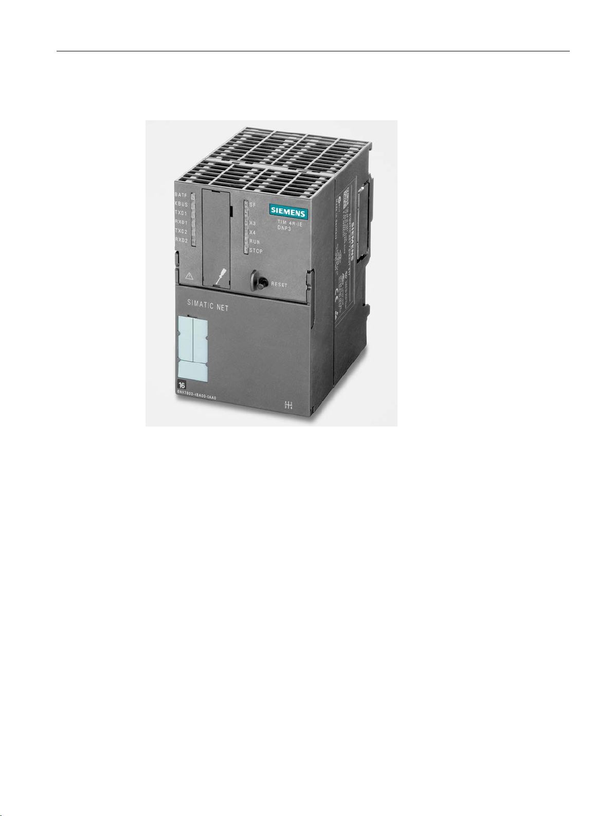
Image 1-2 TIM 4R-IE DNP3
● TIM without integrated modem, double width
● Compact unit that can be used in a wide variety of situations:
– As a communications processor (CP) in an S7-300
– As a standalone device combined with an S7-400 or S7-400H via the Ethernet
interface.
● It has four interfaces:
– 2 x RJ-45 interface for attachment to Ethernet
Allows DNP3 communication via IP-based networks (LAN or WAN).
– 2 x combined RS-232/RS-485 interface
Allows DNP3 communication with a modem connected (classic WAN) or the
connection of MODBUS slaves.
The interface standard (RS-232/RS-485) is specified in the interface configuration.
All four interfaces can be used at the same time for DNP3 communication. The four
transmission paths can all be different and operated independently.
TIM DNP3
System Manual, 12/2015, C79000-G8976-C253-04
17

Uses and properties of the TIM
Design of the TIM 4R-IE DNP3
1.3 TIM 4R-IE DNP3 - Overview
● DNP3 communication
The SIMATIC devices named above can use DNP3 communication:
– Via any two WAN networks with DNP3 subscribers
– via two IP-based networks (WAN or LAN) with DNP3 subscribers
The four transmission paths can all be different and operated independently. All
interfaces can be used for the establishment of redundant transmission paths.
● When installed as a CP in an S7-300, the following communication is also possible:
– With the CPU
– Via the MPI interface of a CPU 312 / 313 / 314 / 315-2 DP / 315F-2 DP with other
CPUs and control center PCs connected to the MPI bus
● The TD7 software is integrated on the TIM (TD7onTIM). It can be used when the TIM is
installed as a CP in an S7-300.
● Message memory: 200 000 data points
● Modules can be replaced without a PG:
– In standalone mode using the optional C-PLUG
– When installed as a CP in an S7-300 over the MMC of the CPU
● Optional: Battery for backup of the stored data messages and the hardware clock
The TIM 4R-IE DNP3 has all the advantages of the SIMATIC S7-300 system design:
● Compact design; double standard width of the SM modules of the SIMATIC S7-300
● Two 9-pin D-sub male connector with a combined RS-232/RS-485 interface for
connecting a modem
● Two RJ-45 jacks for connection to Ethernet; industrial design with additional collar for
inserting the IE FC RJ-45 Plug 180
● 2-pin plug-in terminal block for connecting the external supply voltage of 24 V DC
● Front LEDs for display of Ethernet and WAN communication
● Simple mounting; the TIM is installed on an S7-300 rail. If the TIM is installed in an
S7-300 as a CP, it is connected to adjacent modules by means of the bus module
connectors. No slot rules apply.
● Can be operated in an expansion rack (ER) in conjunction with the IM 360/361. This
allows the TIM to be combined with a C7 control system, with the newer C7 control
systems it can also be combined using the supplied I/O expansion cable.
● Can be operated without a fan
● A backup battery and a memory module (C-PLUG) can be installed as options.
TIM DNP3
18 System Manual, 12/2015, C79000-G8976-C253-04

Uses and properties of the TIM
1.4
Communications services of the TIM
DNP3 communication
DNP3 conformity level of the TIM
S7 communication
Connecting MODBUS slaves
1.4 Communications services of the TIM
The communication of the TIM is based on the DNP3 SPECIFICATION Version 2.x
(2007/2009).
This handles the data traffic for the S7-CPU or for the control center PC with the aid of the
DNP3 protocol via the relevant network.
The DNP3 specification divides devices into classes according to their range of functions.
The DNP3 TIM supports the DNP3 implementation levels 1 - 4 according to the DNP3
specification (DNP3 Application Layer protocol Level).
Some communications objects of the TIM provide functions that go beyond the DNP3
specification, refer to the section Supported DNP3 object groups (Page 162). The DNP3
implementation level of these objects is designated "5".
To ensure that the communications functions are possible during operation, the
implementation level of every DNP3 subscriber in the project is specified in the TD7onTIM
configuration.
The TIM supports S7 communication and PG/OP communication with the following
functions:
● PG functions
● Operator control and monitoring functions (HMI)
● PUT/GET (TIM 4R-IE only)
The TIM 4R-IE supports the PUT/GET services as client and server for data exchange
with remote S7-300/400 stations.
Devices that communicate using the MODBUS protocol can be connected as MODBUS
slaves to a SIMATIC S7 station with a DNP3 TIM. The TIM of the S7 station operates as
MODBUS master.
The communication is handled in the S7 station via the serial interface of a DNP3 TIM. The
serial interface of the TIM is configured for this purpose in the SINAUT configuration tool for
the MODBUS protocol.
You will find the number of MODBUS slaves that can be connected per station in the section
Configuration limits (Page 28).
TIM DNP3
System Manual, 12/2015, C79000-G8976-C253-04
19

Uses and properties of the TIM
DNP3 subscriber types
Master
Synonym: DNP3 master station
Outstation
Synonym: DNP3 station
DNP3 subscriber types supported by the TIM
DNP3 master station
1.4 Communications services of the TIM
The following subscriber types are specified in the DNP3 specification:
●
For the subscriber type "Master", the term "DNP3 master station" is used in this manual.
A master station is a higher-level controlling device.
When using DNP3 TIM modules, the following devices can operate as the DNP3 master
station:
– DNP3 TIM
– Control center system
System supported by the DNP3 master function, for example an OPC client system.
●
For the subscriber type "Outstation", the term "DNP3 station" is used in this manual.
As a lower-level system, the DNP3 station sends process data (measured values,
statuses) to the DNP3 master station and receives switching or setpoint commands from
the DNP3 master station.
The following DNP3 subscriber types are supported by the TIM modules:
●
Master in the sense of the DNP3 specification
The DNP3 master station is a DNP3 TIM in an S7-300/S7-400 station.
Due to the lower performance of the TIM 3V IE DNP3 (max. 8 possible connections), the
TIM 4R IE DNP3 is recommended as the master station TIM.
In the case of the TIM 3V IE DNP3, the output device for the process data is the
connected S7 CPU.
If a TIM 4R-IE DNP3 is used, the process data can be sent to control systems or other
output devices via other interfaces of the module.
The polling of the stations is specified in the configuration of the TIM.
TIM DNP3
20 System Manual, 12/2015, C79000-G8976-C253-04

Uses and properties of the TIM
DNP3 station
"Node station"
Setting the DNP3 subscriber type on the interface of the TIM
Master station function
Station function
Node station function
1.5
DNP3 device attributes of the TIM
Device attributes
Attribute
Meaning
Return value of the DNP3 TIM
211
Number of user-defined attributes
Not supported (negative acknowledgment)
sage
1.5 DNP3 device attributes of the TIM
●
Outstation in the sense of the DNP3 specification
TIM 3V-IE DNP3 or TIM 4R-IE DNP3 in an S7-300/S7-400 station
●
S7 station with a TIM 4R-IE DNP3, that connects two DNP3 networks. It has at least the
following connections:
– Connection to the DNP3 master station via LAN or WAN
– Connection to hierarchically lower-level DNP3 stations via LAN or WAN
The DNP3 subscriber type is set in the configuration using the "Connection mode" of the
Ethernet interfaces of the TIM.
●
The setting of the master station function on an interface has the effect that the TIM
functions as a DNP3 master station on this interface.
●
The setting of the station function on an interface has the effect that the TIM functions as
a DNP3 station on this interface.
●
The two interfaces with the "Node station" setting must therefore be connected once to
the master station and once to the lower-level DNP3 network.
You make the settings for the DNP3 functions of the interfaces in the STEP 7 configuration
of the TIM, refer to the section "Interfaces" tab (Page 119).
The DNP3 protocol defines a series of device attributes that identify the functions of the
devices of different manufacturers. A DNP3 master station can query and, if required,
evaluate the attributes of the connected stations.
The DNP3 TIMs support the following device attributes:
Table 1- 1 Device attributes of the TIM modules
212 - 215 Number of data set prototypes In each case 0
216 Number of binary commands (object 12) in a mes-
TIM DNP3
System Manual, 12/2015, C79000-G8976-C253-04
10
21

Uses and properties of the TIM
Attribute
Meaning
Return value of the DNP3 TIM
217
Accuracy of the TIM time stamp
10 ms
219
Support of analog output events
Not supported (negative acknowledgment)
221
Number of analog outputs
Max. index +1
222
Support of binary output events
Not supported (negative acknowledgment)
223
Max. index of the binary outputs
According to the configuration
224
Number of binary outputs
Max. index +1
225
Support of frozen counter events
Is supported
226
Support of frozen counters
Is supported
227
Support of counter events
Is supported
228
Max. index of the counters
According to the configuration
229
Number of counters
Max. index +1
230
Support of frozen analog inputs
Not supported (negative acknowledgment)
231
Support of analog inputs
Is supported
232
Max. index of the analog inputs
According to the configuration
233
Number of analog inputs
Max. index +1
234
Support of double bit inputs
Not supported (negative acknowledgment)
235
Max. index of double bit inputs
0
236
Number of double bit inputs
0
237
Support of event messages with binary inputs
Is supported
238
Max. index of the binary inputs
According to the configuration
direction (station → master station)
ceive direction (master station → station)
242
TIM software version
Software version
243
TIM hardware version
Hardware version
244
Not defined in the protocol specification
-
245
User-specified string (location)
Not supported (negative acknowledgment)
246
User-specified string (code)
MAC address as string
247
User-specified string (name)
Not supported (negative acknowledgment)
248
Serial number of the TIM
Not supported (negative acknowledgment)
master station
250
Product name and model
Order number as string
252
Vendor
SIEMENS AG
1.5 DNP3 device attributes of the TIM
218 Time for which the time stamp accuracy can be
maintained following synchronization.
220 Max. index of the analog outputs According to the configuration
600 s
239 Number of binary inputs Max. index +1
240 Max. size of the application layer fragments in send
241 Max. size of the application layer fragments in re-
249 DNP3 implementation level Value of the configured conformity level of the DNP3
2048 bytes
2048 bytes
TIM DNP3
22 System Manual, 12/2015, C79000-G8976-C253-04

Uses and properties of the TIM
Detailed information on DNP3 attributes in the DNP3 device profile
TIM 3V-IE DNP3
TIM 4R-IE DNP3
1.6
Other properties of the TIM
Compatible SIMATIC families
Can be used in SIMATIC family:
S7-300
S7-400
TIM 3V-IE DNP3 • no
TIM 4R-IE DNP3 • •
Interfaces
Ethernet RJ-45 port
Serial interface for an exter-
nal modem or for connecting
MODBUS slaves
(RS232/RS485)
1.6 Other properties of the TIM
You will find a detailed overview of the attributes and properties specified in the DNP3
protocol and supported by the two DNP3 TIM modules in the DNP3 device profile.
You will find the DNP3 device profiles on the Internet pages of Siemens Automation
Customer Support under the following entry IDs:
●
Link: (https://support.industry.siemens.com/cs/ww/en/view/103655295)
●
Link: (https://support.industry.siemens.com/cs/ww/en/view/103655863)
The following table shows the SIMATIC families in which the two TIM variants can be used.
The table below shows the number of interfaces of the two TIM variants.
TIM 3V-IE DNP3 1 1
(RS232)
TIM 4R-IE DNP3 2 2
TIM DNP3
System Manual, 12/2015, C79000-G8976-C253-04
23

Uses and properties of the TIM
DNP3 communication between stations
Direct communication
Inter-station communication
Remote programming
1.7
Transmission types and connection establishment
Transmission types (prioritization)
No event class (static)
1.7 Transmission types and connection establishment
Depending on the network type via which the DNP3 stations communicate, communication
between the DNP3 stations is handled as follows:
●
The DNP3 stations are connected via the following network types:
– Ethernet
– Dial-up network
A direct connection is established.
●
The DNP3 stations are connected via the following network types:
– DNP3 dedicated line
The connection is always via the CPU of the DNP3 master station or a higher-level node
station.
Data received in the master station or node station from the transmitting source station is
initially stored on the CPU of the master or node station. For this to be possible, receive
objects must be configured on the TIM of the master or node station.
In a second step, the data must then be read out of the CPU by send objects and
forwarded to the destination station.
Diagnostics and programming functions provided by SIMATIC and SIMATIC NET
Telecontrol for station automation and telecontrol communication can be used via Ethernet
while process data transmission is active.
You will find details in the section SINAUT diagnostics and service tool (Page 242).
The priority of the transfer of the process values from the station to the master station is
configured in the parameter box "Send parameters" for sending communications objects:
The configuration of the send parameters is described in the following section:
Data objects: Partner and send parameters (Page 194)
●
The data is read out of the image memory of the station TIM when it is polled by the
DNP3 master station (class 0 poll).
TIM DNP3
24 System Manual, 12/2015, C79000-G8976-C253-04

Uses and properties of the TIM
Event class 1, 2 or 3
Connection establishment
Master station connections
Connections between stations
1.7 Transmission types and connection establishment
●
The data is stored as an event in the send buffer and actively transferred to the DNP3
master station.
You will find detailed information about the event classes in the section Classification of
the data according to the type of transmission (Page 161).
Transfer of the data can be triggered by various criteria:
– Reaching a configured number of events in the send buffer of the TIM
The configuration is described in the following section:
"DNP3 parameters" dialog (Page 123) > "DNP3 event parameters" tab
For dial-up networks, you will find further setting options in the following section:
Configuring WAN network nodes (Page 99)
– Settable trigger conditions:
- Change-driven transmission
- Cyclic transmission
- Time-driven transmission
The configuration is described in the following section:
Data objects: Memory area and triggers of the channels (Page 200)
●
The initiative for connection establishment depends on the transmission type configured
for a data point:
– Static data points
The current values of all data points (including the events) are always transferred as
the reply to polls by the DNP3 master station. The initiative for connection
establishment comes from the DNP3 master (see above "Command direction"
parameter).
– Data points configured as an event
The value of a data point configured as an event is transferred on the initiative of the
station, see above (event classes).
●
To allow a station to establish the connection to a partner station actively, the "Command
direction" parameter must be enabled in the sending objects (TD7onTIM configuration >
TIM with TD7onTIM > Object > Send parameter).
TIM DNP3
System Manual, 12/2015, C79000-G8976-C253-04
25

Uses and properties of the TIM
1.8
Message memory of the TIM for events
Message memory for events
Note
Reducing the size of the message memory
The
transmission of several thousand events via connections with a low transmission speed
(modem) takes a relatively long time, a reduction may be practical.
1.9
Time synchronization
Options for time-of-day synchronization of DNP3 stations
Note
Avoiding time-of-day inconsistencies
N
•
•
1.8 Message memory of the TIM for events
overall size of the message memory can be configured and can be reduced. Since the
The TIM saves the data messages (including the time stamp) of data points that are
configured as an event. This reduces the data loss if disturbances occur on the
communications path or if a partner fails.
Size of the message memory:
● TIM 3V-IE DNP3: 64 000 events
● TIM 4R-IE DNP3: 200 000 events
If you use a backup battery in the TIM 4R-IE DNP3, events are retained even if there is a
power outage. On return of power, the connected DNP3 master stations can read these
events.
If there are several DNP3 master stations connected, the available message memory of a
station is divided up according to the number of master stations.
The system time of the station TIM of a DNP3 station can be set in two ways as described
below:
● Time-of-day synchronization using DNP3 mechanisms
● Time-of-day synchronization with NTP (Network Time Protocol)
(for TIM 4R-IE DNP3 only)
ote the following points relating to time-of-day synchronization:
Make sure that only one subscriber ever operates as the time-of-day master in a DNP3
network.
Make sure that only one of the methods of time-of-day synchronization listed below is
TIM DNP3
26 System Manual, 12/2015, C79000-G8976-C253-04
used.

Uses and properties of the TIM
Time-of-day synchronization using DNP3 mechanisms
Time-of-day synchronization with NTP
Configuration
1.9 Time synchronization
The system time of the station TIM can be set by a PC of the connected DNP3 master
station.
If the TIM module has established a connection to the DNP3 master station, the TIM module
requests time-of-day synchronization by the master station in the accompanying internal
indication bit "IIN1.4 [NEED_TIME]".
If the master station supports this function, it sends time-of-day messages with the time of
day to the TIM module. The TIM system time is set whenever a time-of-day message is
received.
Remember that the time of day of DNP3 master stations in UTC format generally does not
take into account daylight saving time or time zones.
To request a renewed time-of-day synchronization, the TIM sets the corresponding IIN1.4 bit
after a configurable time has elapsed since the last time-of-day synchronization. The
synchronization cycles are specified in the configuration.
The time of day synchronization using NTP is only supported by the TIM 4R IE DNP3. It is
intended for the TIM as DNP3 master station.
The following use of the two Ethernet interfaces of the TIM 4R IE DNP3 is a practical
solution:
● One Ethernet interface for connecting the DNP3 network
● One Ethernet interface for connecting to one or two NTP servers
As a result, the two networks are separated from each other.
The TIM supports the following variants of NTP:
● NTP
time-of-day synchronization method without authentication
● NTP (secure)
The secure method NTP (secure) uses authentication with symmetrical keys according to
the hash algorithms MD5 or SHA-1.
You configure time-of-day synchronization in STEP 7, refer to the section Configuring timeof-day synchronization (Page 134).
TIM DNP3
System Manual, 12/2015, C79000-G8976-C253-04
27

Uses and properties of the TIM
1.10
Configuration limits
Number of communications partners (connection resources) per TIM
TIM configured as DNP3 master station / node station
TIM 4R-IE DNP3
TIM 3V-IE DNP3
TIM configured as DNP3 station
TIM 4R-IE DNP3
TIM 3V-IE DNP3
Note
Double the connection resources with direct communication between stations (only via
Ethernet or dial-up network)
Note that when there is direct communication between two stations, 2 connection resources
are occupied pe
connection.
1.10 Configuration limits
The maximum number of communications partners is the maximum possible number of
DNP3 connections (sessions) per TIM.
You will find the connection resources in the form of the table after the following listing.
●
Number in total: Max. 128,
of which:
– Pro Ethernet interface:
- Configured with master station function: Max. 64
- Configured with station function: Max. 16
– Pro RS-232 interface:
- Configured with master station function: Max. 32
- Configured with station function: Max. 16
●
Number in total: Max. 8,
of which:
– Via the Ethernet interface: Max. 8
– Via the RS-232 interface: Max. 8
●
Number in total: Max. 32,
of which:
– Per Ethernet interface Max. 16
– Per RS-232 interface: Max. 16
●
Number in total: Max. 8,
of which:
– Via the Ethernet interface: Max. 8
– Via the RS-232 interface: Max. 8
r station: One for the master station connection, one for the station
TIM DNP3
28 System Manual, 12/2015, C79000-G8976-C253-04

Uses and properties of the TIM
TIM type
Subscriber type /
interface configuration
Max. number of
connections per
TIM in total
Interface
Network type
Max. number of
connections per
interface
Ethernet 1
TCP
64
Dedicated line
32
Dial-up network
32
Dedicated line
32
Dial-up network
32
Ethernet 1
TCP
16
Ethernet 2
TCP
16
Dedicated line
16
Dial-up network
16
Dedicated line
16
Dial-up network
16
Ethernet
TCP
8
Dedicated line
8
Dial-up network
8
Ethernet
TCP
8
Dedicated line
8
Dial-up network
8
*
obtained from the information in the "Master station" or "Station" rows.
Number of communications objects per TIM
Size of the message memory for events
1.10 Configuration limits
Table 1- 2 Overview of the connection resources
TIM 4R-IE DNP3 Master station 128 *
Ethernet 2 TCP 64
RS232 no. 1
RS232 no. 2
Station 32
RS232 no. 1
RS232 no. 2
TIM 3V-IE DNP3 Master station /
node station
Station 8
The total number of 128 also applies to the TIM 4R IE DNP3 as a node station. The maximum number per interface is
8
RS232
RS232
The maximum number of communications objects for DNP3 communication per TIM is 100.
● TIM 3V-IE DNP3: 64 000 events
● TIM 4R-IE DNP3: 200 000 events
TIM DNP3
System Manual, 12/2015, C79000-G8976-C253-04
29

Uses and properties of the TIM
Number of S7 connections via Ethernet
TIM 4R-IE DNP3
TIM 3V-IE DNP3
Number of MODBUS slaves per station
1.11
Scope of delivery
Bus module connector
Adapter cable foe TIM 4R-IE DNP3
Documentation
1.11 Scope of delivery
In addition to the DNP3 connections, the number of possible S7 connections via the Ethernet
interface is as follows:
●
Number in total: Max. 5,
of which:
– 2 configurable S7 connections
– 2 PG connections
– 1 OP connection
●
Number in total: Max. 3,
of which:
– 2 PG connections
– 1 OP connection
No S7 connections can be established via the serial interface.
The maximum number of MODBUS slaves that can be connected to the serial interface of a
TIM depends on the configured interface standard:
● RS-232: Maximum of 1 MODBUS slave
● RS-485: Maximum of 8 MODBUS slaves
In addition to the TIM module, the following components ship with the product:
Both TIM modules are supplied with a bus module connector allowing the TIM to be installed
in an S7-300 as a CP.
The adapter cable for the second RS-232/RS-485 interface ships with the TIM 4R-IE DNP3.
The "SIMATIC NET Manual Collection" with documentation ships with both TIM modules.
You will find the link to the current edition on the Internet in the preface of this manual.
TIM DNP3
30 System Manual, 12/2015, C79000-G8976-C253-04
 Loading...