

Siemens SIMATIC TI505,SIMATIC TI500 User Manual

SIMA
TIC TI505/TI500
MODNIM
User
Manual
Order Number: PPX:505-8122-1
Manual Assembly Number: 2586546-0083
Original Edition

Copyright
1993 by Siemens Industrial Automation, Inc.
All Rights Reserved — Printed in USA
Reproduction,
contents is not permitted without express consent of
Siemens Industrial
created by patent grant or registration of a utility model or
design, are reserved.
Since Siemens Industrial Automation, Inc. does not possess
full access to data concerning all of the uses and applications
of customer’s products, we do not assume responsibility either
for customer product design or for any infringements of patents
or rights of others which may result from our assistance.
01/21/92
transmission or use of this document or
Automation, Inc. All rights, including rights
T
echnical data is subject to change.
W
e check the contents of every manual for accuracy at the
time it is approved for printing; however
undetected errors. Any errors found will be corrected in
subsequent editions. Any suggestions for improvement are
welcomed.
, there may be

MANUAL PUBLICA
TION HISTOR
Y
SIMATIC
Or
Refer to this history in all correspondence and/or discussion about this manual.
Event Date Description
Original Issue
TI505/TI500 MODNIM User Manual
der Manual Number: PPX:505-8122-1
03/93
Original Issue (2801280–0001), Softwar
e Release 3.0

LIST
OF EFFECTIVE P
Pages Description Pages Description
Cover/Copyright Original
History/Effective
iii — ix
1-1 — 1-20 Original
2-1 — 2-39 Original
A-1 — A-4
B-1 — B-2
C-1 — C-3
D-1 — D-6
Index-1 — Index-3
Registration Original
Pages
AGES
Original
Original
Original
Original
Original
Original
Original

Preface
Chapter 1 Installation and Set-up
Contents
1.1 Modbus
Modbus
Modbus
Transmission
1.2 Quick
1.3 Setting
1.4 Installing
Refer
General
Procedures 1-4
Handling
Inspecting
Getting
the Dipswitches
Dipswitch
Setting
Selecting
Data T
Stopbit
Parity/No
Odd/Even
ASCII/RTU
RTS/CTS
Y/C
Installing
Installing
the Network Addr
ransmission Rate
Selection
Coil Selection
Communications Overview
Network Characteristics
Pr
otocol 1-2.
Modes
ence Installation Steps
Requir
. . . . . . . . . . . . . . . . . . . . . . . . . . . . . . . . . . . . . . . . . . . . . . . . . . . . . . . . . . . . . . . . . . . . .
the Module
the Module
Started with Configuration and Installation
Functions
Network Configuration Parameters
Parity Selection
Parity Selection
Mode Selection
Handshaking
the MODNIM
the Series 505 MODNIM in the I/O Base
the Series 500 MODNIM in the I/O Base
. . . . . . . . . . . . . . . . . . . . . . . . . . . . . . . . . . . . . . . . . . . . . . . . . . . . . . . . . . . . . .
. . . . . . . . . . . . . . . . . . . . . . . . . . . . . . . . . . . . . . . . . . . . . . . . . . . . . . . . . . . .
ements 1-4.
. . . . . . . . . . . . . . . . . . . . . . . . . . . . . . . . . . . . . . . . . . . . . . . . . . . . . . . . .
. . . . . . . . . . . . . . . . . . . . . . . . . . . . . . . . . . . . . . . . . . . . . . . . . . . . . . . . . .
. . . . . . . . . . . . . . . . . . . . . . . . . . . . . . . . . . . . . . . . . . . . . . . . . . . . . . . . .
. . . . . . . . . . . . . . . . . . . . . . . . . . . . . . . . . . . . . . . . . . . . . . . . . . . . . . . . .
. . . . . . . . . . . . . . . . . . . . . . . . . . . . . . . . . . . . . . . . . . . . . . . . . . . . . . . . . . . .
ess 1-6.
. . . . . . . . . . . . . . . . . . . . . . . . . . . . . . . . . . . . . . . . . . . . . . . . . . . .
. . . . . . . . . . . . . . . . . . . . . . . . . . . . . . . . . . . . . . . . . . . . . . . . . . . . . . . . .
. . . . . . . . . . . . . . . . . . . . . . . . . . . . . . . . . . . . . . . . . . . . . . . . . . . . . . . . . . . . . . .
. . . . . . . . . . . . . . . . . . . . . . . . . . . . . . . . . . . . . . . . . . . . . . . . . . . . . . .
. . . . . . . . . . . . . . . . . . . . . . . . . . . . . . . . . . . . . . . . . . . . . . . . . . . . .
. . . . . . . . . . . . . . . . . . . . . . . . . . . . . . . . . . . . . . . . . . . . . . . . . . . . . .
. . . . . . . . . . . . . . . . . . . . . . . . . . . . . . . . . . . . . . . . . . . . . . . . . . . . . . . . . .
. . . . . . . . . . . . . . . . . . . . . . . . . . . . . . . . . . . . . . . . . . . . . . . . . . . . . . . . . . . . .
. . . . . . . . . . . . . . . . . . . . . . . . . . . . . . . . . . . . . . . . . . . . . . . . . . . . . . . . .
. . . . . . . . . . . . . . . . . . . . . . . . . . . . . . . . . . . . . . . . . . . .
. . . . . . . . . . . . . . . . . . . . . . . . . . . . . . . . . . . . . . . . . . . . . . .
. . . . . . . . . . . . . . . . . . . . . . . . . . . . . . . . . . . . . . . . . . . . . .
. . . . . . . . . . . . . . . . . . . . . . . . . . . . . .
. . . . . . . . . . . . . . . . . . . . . . . . . . . . . . . . . . . .
. . . . . . . . . . . . . . . . . . . . . . . . . . . . . . . . .
. . . . . . . . . . . . . . . . . . . . . . . . . . . . . . . . .
1-2.
1-2.
1-2.
1-4.
1-5.
1-5.
1-5.
1-6.
1-6.
1-7.
1-7.
1-7.
1-7.
1-7.
1-7.
1-7.
1-7.
1-10.
1-10.
1-12.
1.5 Switches
Switches
Reset
Test
Local/Remote
Status
1.6 Diagnostic Tests 1-16.
Built-in
Power-up
Run-time
User-Initiated
and Indicator Lights
and Buttons
Button
Button
Indicator Lights
Diagnostic T
. . . . . . . . . . . . . . . . . . . . . . . . . . . . . . . . . . . . . . . . . . . . . . . . . . . . . . . . . . . . . . . . . . .
. . . . . . . . . . . . . . . . . . . . . . . . . . . . . . . . . . . . . . . . . . . . . . . . . . . . . . . . . . . . . . . . . . . .
Switch
Self T
est 1-16.
Self T
ests 1-17.
Self T
. . . . . . . . . . . . . . . . . . . . . . . . . . . . . . . . . . . . . . . . . . . . . . . . . . .
. . . . . . . . . . . . . . . . . . . . . . . . . . . . . . . . . . . . . . . . . . . . . . . . . . . . . . . . . .
. . . . . . . . . . . . . . . . . . . . . . . . . . . . . . . . . . . . . . . . . . . . . . . . . . . . . . . . . .
. . . . . . . . . . . . . . . . . . . . . . . . . . . . . . . . . . . . . . . . . . . . . . . . . . . . . . . . . .
. . . . . . . . . . . . . . . . . . . . . . . . . . . . . . . . . . . . . . . . . . . . . . . . . . . . . . . . . . . . . . . .
ests 1-16.
. . . . . . . . . . . . . . . . . . . . . . . . . . . . . . . . . . . . . . . . . . . . . . . . . . . . . . . . .
. . . . . . . . . . . . . . . . . . . . . . . . . . . . . . . . . . . . . . . . . . . . . . . . . . . . . . . . . . . . . .
. . . . . . . . . . . . . . . . . . . . . . . . . . . . . . . . . . . . . . . . . . . . . . . . . . . . . . . . . . . . . .
est 1-18.
. . . . . . . . . . . . . . . . . . . . . . . . . . . . . . . . . . . . . . . . . . . . . . . . . . . . . . . . . .
Contents iii
1-14.
1-14.
1-14.
1-14.
1-14.
1-15.

1.7 Establishing
Verifying
Connecting
Recommended
Building
Communications
that the MODNIM is Logged into the PLC
the Network Cables
Communication Cables
a Cable
. . . . . . . . . . . . . . . . . . . . . . . . . . . . . . . . . . . . . . . . . . . . . . . . . . . . . . . . . . . . . . .
Chapter 2 Modbus Commands
. . . . . . . . . . . . . . . . . . . . . . . . . . . . . . . . . . . . . . . . . . . . . . . . . .
. . . . . . . . . . . . . . . . . . . . . . . . . . . . . . .
. . . . . . . . . . . . . . . . . . . . . . . . . . . . . . . . . . . . . . . . . . . . . . .
. . . . . . . . . . . . . . . . . . . . . . . . . . . . . . . . . . . . . . . .
1-19.
1-19.
1-20.
1-20.
1-20.
2.1 Modbus
Modbus
The
The
The
The
The
The
The
The
2.2 Modbus
The R
The R
Message
Checksum 2-5
Invalid
2.3 Comparing
Modbus
Addressing 2-7
Address
2.4 Modbus
Introduction 2-8
Code
Code
Code
Code
Code 05 — W
Code 06 — W
Code
Code
Code
Code
Code 15 — W
Code 16 — W
Code
Pr
Pr
ASCII T
Start Field
Addr
ess Field
Function Field
Data Field
LRC Field
EOF Field
Ready Field
Pr
TU T
ransmission Frame
TU Frame Fields
Delineation
Characters and Messages
Functions vs. TIWAY Commands
Limits
Function Descriptions
01 — Read Coil Status
02 — Read Input Status
03 — Read Output Registers
04 — Read Input Registers
07 — Read Exception Status
08 — Execute Diagnostics
11 — Get Comms Event Counter
12 — Get Comms Event Log
17 — Report Slave ID
otocol Overview — ASCII T
otocol 2-2.
ransmission Frame
otocol Overview — R
. . . . . . . . . . . . . . . . . . . . . . . . . . . . . . . . . . . . . . . . . . . . . . . . . . . . . . . . . . . . . . . . . . . . .
Modbus Functions with TIWAY I Network Commands
. . . . . . . . . . . . . . . . . . . . . . . . . . . . . . . . . . . . . . . . . . . . . . . . . . . . . . . . . . . . . . . . . . . . .
. . . . . . . . . . . . . . . . . . . . . . . . . . . . . . . . . . . . . . . . . . . . . . . . . . . . . . . . . . . . . .
. . . . . . . . . . . . . . . . . . . . . . . . . . . . . . . . . . . . . . . . . . . . . . . . . . .
. . . . . . . . . . . . . . . . . . . . . . . . . . . . . . . . . . . . . . . . . . . . . . . . . . . . . . . . . . . . . . . . . .
. . . . . . . . . . . . . . . . . . . . . . . . . . . . . . . . . . . . . . . . . . . . . . . . . . . . . . . . . . . . . .
. . . . . . . . . . . . . . . . . . . . . . . . . . . . . . . . . . . . . . . . . . . . . . . . . . . . . . . . . . . . . .
. . . . . . . . . . . . . . . . . . . . . . . . . . . . . . . . . . . . . . . . . . . . . . . . . . . . . . . . . . . . . . . . .
. . . . . . . . . . . . . . . . . . . . . . . . . . . . . . . . . . . . . . . . . . . . . . . . . . . . . . . . . . . . . . . . . .
. . . . . . . . . . . . . . . . . . . . . . . . . . . . . . . . . . . . . . . . . . . . . . . . . . . . . . . . . . . . . . . . . .
. . . . . . . . . . . . . . . . . . . . . . . . . . . . . . . . . . . . . . . . . . . . . . . . . . . . . . . . . . . . . . . .
. . . . . . . . . . . . . . . . . . . . . . . . . . . . . . . . . . . . . . . . . . . . . . . . . . . . .
. . . . . . . . . . . . . . . . . . . . . . . . . . . . . . . . . . . . . . . . . . . . . . . . . . . . . . . . . . .
. . . . . . . . . . . . . . . . . . . . . . . . . . . . . . . . . . . . . . . . . . . . . . . . . . . . . . . . . .
. . . . . . . . . . . . . . . . . . . . . . . . . . . . . . . . . . . . . . . . . . . . . . . . . . . . . . . . . . . . . . . . . .
. . . . . . . . . . . . . . . . . . . . . . . . . . . . . . . . . . . . . . . . . . . . . . . . . . . . . . . . . . . . . . . . . . . .
. . . . . . . . . . . . . . . . . . . . . . . . . . . . . . . . . . . . . . . . . . . . . . . . . . .
rite a Single Coil
rite a Single Register
rite Multiple Coils
rite Multiple Registers
. . . . . . . . . . . . . . . . . . . . . . . . . . . . . . . . . . . . . . . . . . . . . . . . . . . . .
ransmission Mode
TU T
ransmission Mode
. . . . . . . . . . . . . . . . . . . . . . . . . . . . . . . . . . . . . . . . . . . . . . .
. . . . . . . . . . . . . . . . . . . . . . . . . . . . . . . . . . . . . . . .
. . . . . . . . . . . . . . . . . . . . . . . . . . . . . . . . . . . . . . . . . . . . . . . . . .
. . . . . . . . . . . . . . . . . . . . . . . . . . . . . . . . . . . . . . . . . . . . . . . . . .
. . . . . . . . . . . . . . . . . . . . . . . . . . . . . . . . . . . . . . . . . . . . . .
. . . . . . . . . . . . . . . . . . . . . . . . . . . . . . . . . . . . . . . . . . . . . . . .
. . . . . . . . . . . . . . . . . . . . . . . . . . . . . . . . . . . . . . . . . . . . . . . . . .
. . . . . . . . . . . . . . . . . . . . . . . . . . . . . . . . . . . . . . . . . . . . . .
. . . . . . . . . . . . . . . . . . . . . . . . . . . . . . . . . . . . . . . . . . . . . .
. . . . . . . . . . . . . . . . . . . . . . . . . . . . . . . . . . . . . . . . . . . . . . . .
. . . . . . . . . . . . . . . . . . . . . . . . . . . . . . . . . . . . . . . . .
. . . . . . . . . . . . . . . . . . . . . . . . . . . . . . . . . . . . . . . . . . . . .
. . . . . . . . . . . . . . . . . . . . . . . . . . . . . . . . . . . . . . . . . . . . . . . . .
. . . . . . . . . . . . . . . . . . . . . . . . . . . . . . . . . . . . . . . . . . . . .
. . . . . . . . . . . . . . . . . . . . . . . . . .
. . . . . . . . . . . . . . . . . . . . . . . . . . . .
. . . . . . . . . . . . . . . . . .
2-2.
2-2.
2-2.
2-2.
2-2.
2-3.
2-3.
2-3.
2-3.
2-4.
2-4.
2-4.
2-4.
2-5.
2-6.
2-6.
2-7.
2-8.
2-8.
2-10.
2-12.
2-13.
2-14.
2-16.
2-17.
2-19.
2-30.
2-31.
2-33.
2-35.
2-36.
2.5 Error
iv Contents
Responses
. . . . . . . . . . . . . . . . . . . . . . . . . . . . . . . . . . . . . . . . . . . . . . . . . . . . . . . . . . . . . . . .
2-38.

Appendix A Network Cable Communications
A.1 Network
Recommended
Building
Cable
A.2 Communications
RS-232-C
Recommended
Appendix
B.1 Exception
Appendix
C.1 Environmental
C.2 MODNIM
Appendix
D.1 Getting
Overview D-2
Hardware
Running
Running
Cables
Cables
Pinouts
Pin Assignments
B
Exception Codes
Codes Supported by the MODNIM
C
Specifications
Specifications
Communications Specifications
D
Using the MODASST Program
Started
. . . . . . . . . . . . . . . . . . . . . . . . . . . . . . . . . . . . . . . . . . . . . . . . . . . . . . . . . . . . . . . . . . . . . . .
Requir
the Pr
the Pr
ogram from the Floppy Disk
ogram fr
. . . . . . . . . . . . . . . . . . . . . . . . . . . . . . . . . . . . . . . . . . . . . . . . . . . . . . . . . . . . . . .
Communication Cables
. . . . . . . . . . . . . . . . . . . . . . . . . . . . . . . . . . . . . . . . . . . . . . . . . . . . . . . . . . . . . . . .
. . . . . . . . . . . . . . . . . . . . . . . . . . . . . . . . . . . . . . . . . . . . . . . . . . . . . . . . . . . . . . . . .
Parameters
Communications Parameters
. . . . . . . . . . . . . . . . . . . . . . . . . . . . . . . . . . . . . . . . . . . . . . . . . . . . . . . . . . . . . . . .
ements D-2.
om the Har
. . . . . . . . . . . . . . . . . . . . . . . . . . . . . . . . . . . . . . . . . . . . . . . . . . .
. . . . . . . . . . . . . . . . . . . . . . . . . . . . . . . . . . . . . . . . . . . . . . . . . . . . . . .
. . . . . . . . . . . . . . . . . . . . . . . . . . . . . . . . . . . . . . . . . . . . . . . . . . .
. . . . . . . . . . . . . . . . . . . . . . . . . . . . . . . . . . . . . . . . . . . . . . . . . . . . . . .
d Disk
. . . . . . . . . . . . . . . . . . . . . . . . . . . . . . . . . . . . . . . .
. . . . . . . . . . . . . . . . . . . . . . . . . . . . . . . . . . .
. . . . . . . . . . . . . . . . . . . . . . . . . . . . . . . . . . . .
. . . . . . . . . . . . . . . . . . . . . . . . . . . . . . . . . . . . . . .
. . . . . . . . . . . . . . . . . . . . . . . . . . . . . . . . . . . . . .
. . . . . . . . . . . . . . . . . . . . . . . . . . . . . . . . . . . . . . . .
A-2.
A-2.
A-2.
A-2.
A-4.
A-4.
A-4.
B-2.
C-2.
C-3.
D-2.
D-2.
D-3.
D.2 Starting
Setting
Setting
D.3 Using
Pr
Setup
Options
Run
Diagnostics
Find
Module Settings
Talk
to Module
Batch
Send fr
Verifying
Pr
ogram Operation
the Communication Port Options
the Remaining Options
ogram Options
. . . . . . . . . . . . . . . . . . . . . . . . . . . . . . . . . . . . . . . . . . . . . . . . . . . . . . . . . . . . . . . . .
. . . . . . . . . . . . . . . . . . . . . . . . . . . . . . . . . . . . . . . . . . . . . . . . . . . . . . . . . . . . . . . .
. . . . . . . . . . . . . . . . . . . . . . . . . . . . . . . . . . . . . . . . . . . . . . . . . . . . . . . . . . .
. . . . . . . . . . . . . . . . . . . . . . . . . . . . . . . . . . . . . . . . . . . . . . . . . . . . . . . . . . . . . . . . .
om File
Communications
. . . . . . . . . . . . . . . . . . . . . . . . . . . . . . . . . . . . . . . . . . . . . . . . . . . . . . . . . . .
. . . . . . . . . . . . . . . . . . . . . . . . . . . . . . . . . . . . . . . . . . . . . . . . . . . .
. . . . . . . . . . . . . . . . . . . . . . . . . . . . . . . . . . . . . . . . . . . . . . . . .
. . . . . . . . . . . . . . . . . . . . . . . . . . . . . . . . . . . . . . . . . . . . . . . . . . . . . . . . .
. . . . . . . . . . . . . . . . . . . . . . . . . . . . . . . . . . . . . . . . . . . . . . . . . . . . . .
D-4.
. . . . . . . . . . . . . . . . . . . . . . . . . . . . . . . . . . . . . . . .
Contents v
D-4.
D-4.
D-5.
D-5.
D-5.
D-6.
D-6.
D-6.
D-6.

List of Figures
Figur
Figur
Figur
Figur
Figur
Figur
Figur
Figur
Figur
Figur
Figur
Figur
Figur
Figur
Figur
Figur
Figur
Figur
Figur
Figur
Figur
Figur
Figur
Figur
Figur
Figur
Figur
Figur
Figur
Figur
Figur
Figur
Figur
Figur
Figur
Figur
Figur
Figur
Figur
Figur
Figur
e 1-1
e 1-2
e 1-3
e 1-4
e 1-5
e 1-6
e 1-7
e 1-8
e 1-9
e 1-10
e 1-11
e 1-12
e 1-13
e 1-14
e 2-1
e 2-2
e 2-3
e 2-4
e 2-5
e 2-6
e 2-7
e 2-8
e 2-9
e 2-10
e 2-11
e 2-12
e 2-13
e 2-14
e 2-15
e 2-16
e 2-17
e 2-18
e 2-19
e 2-20
e 2-21
e 2-22
e 2-23
e 2-24
e 2-25
e 2-26
e 2-27
Multidrop
Quick
Address
Dipswitch
Series
Series
Installing
Series
Keying
Installing
Series
LED
LED
Sample
ASCII T
RTU T
Bit
Orientation
Read
Read
Read
Read
Read
Read
Read
Read
Read
Read
Write
Read
Write
Write
Read
Read
Exception
Execute
Execute
Get
Get
Get
Get
Write
and Point-to-point Configurations
Reference Installation Pr
Setting Examples
Settings for Network Data T
505 MODNIM Switches and LEDs
500 MODNIM Switches and LEDs
the Series 505 MODNIM in the I/O Base
505 MODNIM Example Dipswitch Settings
the I/O Base Slot for the Series 500 MODNIM
the Series 500 MODNIM in the I/O Base
505 and 500 MODNIM Indicator Lights
Status during Power-Up Self T
Status during Nor
I/O Definition Chart
ransmission Frame
ransmission Frame
. . . . . . . . . . . . . . . . . . . . . . . . . . . . . . . . . . . . . . . . . . . . . . . . . . . . . . . . . . . . .
Coil Status Example — Request
Coil Status Example — Response
Coil Status Example — Data Field
Input Status Example — Request
Input Status Example — Response
Input Status Example — Data Field
Output Register Example — Request
Output Register Example — Response
Input Register Example — Request
Input Register Example — Response
a Single Coil Example — Request
Input Register Example — Response
a Single Register Example — Request
a Single Register Example — Response
Exception Status Example — Request
Exception Status Example — Response
Status Bits
Diagnostics Example — Request
Diagnostics Example — Response
Comms Event Counter Example — Request
Comms Event Counter Example — Response
Comms Event Log Example — Request
Comms Event Log Example — Response
Multiple Coils Example — Request
mal Run-T
. . . . . . . . . . . . . . . . . . . . . . . . . . . . . . . . . . . . . . . . . . . . . . . . . . . . .
. . . . . . . . . . . . . . . . . . . . . . . . . . . . . . . . . . . . . . . . . . . . . . . . . . . . . .
ocedures 1-4.
. . . . . . . . . . . . . . . . . . . . . . . . . . . . . . . . . . . . . . . . . . . . . . . . . .
ransmission Rates
est 1-16.
ime Operation
. . . . . . . . . . . . . . . . . . . . . . . . . . . . . . . . . . . . . . . . . . . . . . .
. . . . . . . . . . . . . . . . . . . . . . . . . . . . . . . . . . . . . . . . . . . . . . . . . . .
. . . . . . . . . . . . . . . . . . . . . . . . . . . . . . . . .
. . . . . . . . . . . . . . . . . . . . . . . . . . . . . . . . . . . .
. . . . . . . . . . . . . . . . . . . . . . . . . . . . . . . . . . . . . .
. . . . . . . . . . . . . . . . . . . . . . . . . . . . . . . . . . . . . .
. . . . . . . . . . . . . . . . . . . . . . . . . . . . . . .
. . . . . . . . . . . . . . . . . . . . . . . . . . . . . . . . . . . . . . .
. . . . . . . . . . . . . . . . . . . . . . . . . . . . . . . . . . . . . . .
. . . . . . . . . . . . . . . . . . . . . . . . . . . . . . . . . . . . . .
. . . . . . . . . . . . . . . . . . . . . . . . . . . . . . . . . . . . .
. . . . . . . . . . . . . . . . . . . . . . . . . . . . . . . . . . . . . .
. . . . . . . . . . . . . . . . . . . . . . . . . . . . . . . . . . . .
. . . . . . . . . . . . . . . . . . . . . . . . . . . . . . . . . . . .
. . . . . . . . . . . . . . . . . . . . . . . . . . . . . . . . .
. . . . . . . . . . . . . . . . . . . . . . . . . . . . . . . .
. . . . . . . . . . . . . . . . . . . . . . . . . . . . . . . . . . .
. . . . . . . . . . . . . . . . . . . . . . . . . . . . . . . . .
. . . . . . . . . . . . . . . . . . . . . . . . . . . . . . . . . . . . .
. . . . . . . . . . . . . . . . . . . . . . . . . . . . . . . . .
. . . . . . . . . . . . . . . . . . . . . . . . . . . . . . . . .
. . . . . . . . . . . . . . . . . . . . . . . . . . . . . . .
. . . . . . . . . . . . . . . . . . . . . . . . . . . . . . . .
. . . . . . . . . . . . . . . . . . . . . . . . . . . . . . .
. . . . . . . . . . . . . . . . . . . . . . . . . . . . . . . . . .
. . . . . . . . . . . . . . . . . . . . . . . . . . . . . . . . .
. . . . . . . . . . . . . . . . . . . . . . . . . . . . . . . .
. . . . . . . . . . . . . . . . . . . . . . . . . . . . . . .
. . . . . . . . . . . . . . . . . . . . . . . . . . . . . . . . . . . .
. . . . . . . . . . . . . . . . . . . . . .
. . . . . . . . . . . . . . . . . . . . . . . . . . . . .
. . . . . . . . . . . . . . . . . . . . . . . . . . . . .
. . . . . . . . . . . . . . . . . . . . . . . . . .
. . . . . . . . . . . . . . . . . . . . . . . . . . . .
. . . . . . . . . . . . . . . . . . . . . . . . . . . . . .
. . . . . . . . . . . . . . . . . . . . . . . . . . . .
. . . . . . . . . . . . . . . . . . . . . . . . . .
1-3.
1-6.
1-7.
1-8.
1-9.
1-10.
1-11.
1-12.
1-13.
1-15.
1-17.
1-19.
2-2.
2-4.
2-6.
2-8.
2-9.
2-9.
2-10.
2-10.
2-11.
2-12.
2-12.
2-13.
2-13.
2-14.
2-15.
2-16.
2-16.
2-17.
2-17.
2-18.
2-19.
2-19.
2-30.
2-30.
2-31.
2-31.
2-33.
vi Contents

Figur
Figur
Figur
Figur
Figur
Figur
Figur
Figur
Figur
Figur
Figur
Figur
Figur
e 2-28
e 2-29
e 2-30
e 2-31
e 2-32
e 2-33
e 2-34
e 2-35
e A-1
e A-2
e A-3
e D-1
e D-2
Coil
Bit Patter
Write
Multiple Coils Example — Response
Write
Multiple Registers Example — Request
Write
Multiple Registers Example — Response
Report
Report
Slave ID Example — Request
Slave ID Example — Response
Exception
Exception
MODNIM
MODNIM
MODNIM
First
Configuration Scr
MODASST
n 2-34.
. . . . . . . . . . . . . . . . . . . . . . . . . . . . . . . . . . . . . . . . . . . . . . . . . . . . . . . . . . .
Response Frame— ASCII Mode
Response Frame — R
TU Mode
to Host (without Handshaking)
to Host (with Handshaking)
to Commer
cial Modem (with Handshaking)
een after Start-Up
Setup Menu
. . . . . . . . . . . . . . . . . . . . . . . . . . . . . . . . . . . . . . . . . . . . . . . . . . . . .
. . . . . . . . . . . . . . . . . . . . . . . . . . . . . . . . . .
. . . . . . . . . . . . . . . . . . . . . . . . . . . . . . . .
. . . . . . . . . . . . . . . . . . . . . . . . . . . . . .
. . . . . . . . . . . . . . . . . . . . . . . . . . . . . . . . . . . . . . .
. . . . . . . . . . . . . . . . . . . . . . . . . . . . . . . . . . . . . .
. . . . . . . . . . . . . . . . . . . . . . . . . . . . . . . . . .
. . . . . . . . . . . . . . . . . . . . . . . . . . . . . . . . . . .
. . . . . . . . . . . . . . . . . . . . . . . . . . . . . . . . . . . .
. . . . . . . . . . . . . . . . . . . . . . . . . . . . . . . . . . . . . . .
. . . . . . . . . . . . . . . . . . . . . . .
. . . . . . . . . . . . . . . . . . . . . . . . . . . . . . . . . . . .
2-34.
2-35.
2-35.
2-36.
2-36.
2-38.
2-38.
A-2.
A-3.
A-3.
D-3.
D-5.
Contents vii

List
of T
T
able 1-1
T
able 1-2
T
able 1-3
T
able 1-4
T
able 2-1
T
able 2-2
T
able 2-3
T
able 2-4
T
able 2-5
T
able 2-6
T
able 2-7
T
able 2-8
T
able A-1
T
able A-2
T
able B-1
T
able C-1
T
able C-2
T
able C-3
ables
Transmission
Status
of Indicator Lights
Indicator
Standard
Modbus
RTU
Terminology
Diagnostic
Diagnostic
Event
Function
Exception
RS-232-C
Communications
Exception
Environmental
MODNIM
Modbus
Status after User-Initiated T
Communication Cables
Functions Supported
Mode T
Byte T
Code 17 Response Options
Connector Pin Assignments
Codes vs. TIWAY Primitives Chart
Mode Characteristics
. . . . . . . . . . . . . . . . . . . . . . . . . . . . . . . . . . . . . . . . . . . . . . . . . . . .
iming 2-4.
Dif
Codes Supported
Bits
ypes 2-32.
Responses
Codes
Specifications
. . . . . . . . . . . . . . . . . . . . . . . . . . . . . . . . . . . . . . . . . . . . . . . . . . . . . . . . . . .
ferences 2-6.
. . . . . . . . . . . . . . . . . . . . . . . . . . . . . . . . . . . . . . . . . . . . . . . . . . . . . . . . . . . . . .
. . . . . . . . . . . . . . . . . . . . . . . . . . . . . . . . . . . . . . . . . . . . . . . . . . . . . . . . . . .
Parameters
. . . . . . . . . . . . . . . . . . . . . . . . . . . . . . . . . . . . . . . . . . . . . . . . . . . . . . . . . . .
Specifications
. . . . . . . . . . . . . . . . . . . . . . . . . . . . . . . . . . . . . . . . . . . . . . . . . . . .
. . . . . . . . . . . . . . . . . . . . . . . . . . . . . . . . . . . . . . . . . . . . . . . . . . . . . . .
. . . . . . . . . . . . . . . . . . . . . . . . . . . . . . . . . . . . . . . . . . . . . . . . . . . .
. . . . . . . . . . . . . . . . . . . . . . . . . . . . . . . . . . . . . . . . . . .
est 1-18.
. . . . . . . . . . . . . . . . . . . . . . . . . . . . . . . . . . . . . .
. . . . . . . . . . . . . . . . . . . . . . . . . . . . . . . . . . . . . . . . . . .
. . . . . . . . . . . . . . . . . . . . . . . . . . . . . . . . . . . . . . . . . . . . . . .
. . . . . . . . . . . . . . . . . . . . . . . . . . . . . . . . . . . . . . . . . . . . . . .
. . . . . . . . . . . . . . . . . . . . . . . . . . . . . . . . . . . . . . . .
. . . . . . . . . . . . . . . . . . . . . . . . . . . . . . . . . . . . . . . .
. . . . . . . . . . . . . . . . . . . . . . . . . . . . . . . . . . . . . . . . . . . . . . .
. . . . . . . . . . . . . . . . . . . . . . . . . . . . . . . . . . . . . . . . . . . . . . .
. . . . . . . . . . . . . . . . . . . . . . . . . . . . . . . . . . . .
1-3.
1-15.
1-20.
2-3.
2-20.
2-22.
2-37.
2-39.
A-4.
A-4.
B-2.
C-2.
C-3.
C-3.
viii Contents

Purpose of this Manual
Preface
This
manual provides the following information on the Series 505 and
Series 500 MODNIM (Modbus Network Interface Module), model
numbers PPX:505–5184 and PPX:500–5184.
•
Basic features of the MODNIM
•
Installation and configuration
•
Diagnostic self-testing procedures
•
Operating instructions
•
Modbus commands and error responses
•
MODNIM specifications
Related Manuals
The following publications contain related information which supplement
this manual.
Series 505 Manuals
• SIMATIC TI505
• SIMA
• SIMATIC TI525/TI535
• SIMATIC TI545
Series 500 Manuals
• SIMATIC
•
• SIMATIC TI560/TI565
The following Gould Modicon publications are also recommended.
•
•
TIC TI505 TISOFT User Manual
TI520C
Series 500 I/O Base User’s Manual
Gould Modbus Protocol
Modbus System Planning
Programming Reference Manual
Hardware and Installation Manual
System Manual
/TI530C
(part no. PI-MBUS-300 Rev B)
Programmable Controller Manual
Programming Manual
(part no. PI-MBUS-PLN)
•
Gould Modicon J474/J475 Interface
Technical Assistance
SIMATIC TI505/TI500 MODNIM User Manual
If you need information that is not included in this manual, or if you have
problems using the module, contact your Siemens Industrial Automation,
Inc. distributor or sales office. If you need assistance in contacting your
distributor or sales office in the United States, call 1–800–964-41
(part no. PI-J475-001 Rev B)
14.
Preface
ix

Chapter 1
1.1 Modbus
Modbus
Modbus
Transmission
1.2 Quick
1.3 Setting
Refer
General
Procedures 1-4
Handling
Inspecting
Getting
Dipswitch
Setting
Selecting
Data T
Stopbit
Parity/No
Odd/Even
ASCII/RTU
RTS/CTS
Y/C
Coil Selection
Installation
Communications Overview
Network Characteristics
Pr
otocol 1-2.
Modes
ence Installation Steps
Requir
. . . . . . . . . . . . . . . . . . . . . . . . . . . . . . . . . . . . . . . . . . . . . . . . . . . . . . . . . . . . . . . . . . . . .
the Module
the Module
Started with Configuration and Installation
the Dipswitches
Functions
the Network Addr
Network Configuration Parameters
ransmission Rate
Selection
Parity Selection
Parity Selection
Mode Selection
Handshaking
. . . . . . . . . . . . . . . . . . . . . . . . . . . . . . . . . . . . . . . . . . . . . . . . . . . . . . . . . . . . . .
. . . . . . . . . . . . . . . . . . . . . . . . . . . . . . . . . . . . . . . . . . . . . . . . . . . . . . . . . . . .
ements 1-4.
. . . . . . . . . . . . . . . . . . . . . . . . . . . . . . . . . . . . . . . . . . . . . . . . . . . . . . . . .
. . . . . . . . . . . . . . . . . . . . . . . . . . . . . . . . . . . . . . . . . . . . . . . . . . . . . . . . . .
. . . . . . . . . . . . . . . . . . . . . . . . . . . . . . . . . . . . . . . . . . . . . . . . . . . . . . . . .
. . . . . . . . . . . . . . . . . . . . . . . . . . . . . . . . . . . . . . . . . . . . . . . . . . . . . . . . .
. . . . . . . . . . . . . . . . . . . . . . . . . . . . . . . . . . . . . . . . . . . . . . . . . . . . . . . . . . . .
ess 1-6.
. . . . . . . . . . . . . . . . . . . . . . . . . . . . . . . . . . . . . . . . . . . . . . . . . . . .
. . . . . . . . . . . . . . . . . . . . . . . . . . . . . . . . . . . . . . . . . . . . . . . . . . . . . . . . .
. . . . . . . . . . . . . . . . . . . . . . . . . . . . . . . . . . . . . . . . . . . . . . . . . . . . . . . . . . . . . . .
. . . . . . . . . . . . . . . . . . . . . . . . . . . . . . . . . . . . . . . . . . . . . . . . . . . . . . .
. . . . . . . . . . . . . . . . . . . . . . . . . . . . . . . . . . . . . . . . . . . . . . . . . . . . .
. . . . . . . . . . . . . . . . . . . . . . . . . . . . . . . . . . . . . . . . . . . . . . . . . . . . . .
. . . . . . . . . . . . . . . . . . . . . . . . . . . . . . . . . . . . . . . . . . . . . . . . . . . . . . . . . .
. . . . . . . . . . . . . . . . . . . . . . . . . . . . . . . . . . . . . . . . . . . . . . . . . . . . . . . . . . . . .
. . . . . . . . . . . . . . . . . . . . . . . . . . . . . . . . . . . . . . . . . . . .
. . . . . . . . . . . . . . . . . . . . . . . . . . . . . . . . . . . . . . . . . . . . . . .
. . . . . . . . . . . . . . . . . . . . . . . . . . . . . . . . . . . . . . . . . . . . . .
. . . . . . . . . . . . . . . . . . . . . . . . . . . . . .
. . . . . . . . . . . . . . . . . . . . . . . . . . . . . . . . . . . .
and Set-up
1-2.
1-2.
1-2.
1-4.
1-5.
1-5.
1-5.
1-6.
1-6.
1-7.
1-7.
1-7.
1-7.
1-7.
1-7.
1-7.
1-7.
1.4 Installing
Installing
Installing
1.5 Switches
Switches
Reset
Test
Local/Remote
Status
1.6 Diagnostic Tests 1-16.
Built-in
Power-up
Run-time
User-Initiated
1.7 Establishing
Verifying
Connecting
Recommended
Building
SIMATIC TI505/TI500 MODNIM User Manual
the MODNIM
the Series 505 MODNIM in the I/O Base
the Series 500 MODNIM in the I/O Base
and Indicator Lights
and Buttons
Button
Button
Indicator Lights
Diagnostic T
. . . . . . . . . . . . . . . . . . . . . . . . . . . . . . . . . . . . . . . . . . . . . . . . . . . . . . . . . . . . . . . . . . .
. . . . . . . . . . . . . . . . . . . . . . . . . . . . . . . . . . . . . . . . . . . . . . . . . . . . . . . . . . . . . . . . . . . .
Switch
. . . . . . . . . . . . . . . . . . . . . . . . . . . . . . . . . . . . . . . . . . . . . . . . . . . . . . . . . . . . . . . .
Self T
est 1-16.
Self T
ests 1-17.
Self T
Communications
that the MODNIM is Logged into the PLC
the Network Cables
Communication Cables
a Cable
. . . . . . . . . . . . . . . . . . . . . . . . . . . . . . . . . . . . . . . . . . . . . . . . . . . . . . . . .
. . . . . . . . . . . . . . . . . . . . . . . . . . . . . . . . . . . . . . . . . . . . . . . . . . . . . . . . . .
. . . . . . . . . . . . . . . . . . . . . . . . . . . . . . . . . . . . . . . . . . . . . . . . . . . . . . . . . .
. . . . . . . . . . . . . . . . . . . . . . . . . . . . . . . . . . . . . . . . . . . . . . . . . . . . . . . . . .
ests 1-16.
. . . . . . . . . . . . . . . . . . . . . . . . . . . . . . . . . . . . . . . . . . . . . . . . . . . . . . . . .
. . . . . . . . . . . . . . . . . . . . . . . . . . . . . . . . . . . . . . . . . . . . . . . . . . . . . . . . . . . . . .
. . . . . . . . . . . . . . . . . . . . . . . . . . . . . . . . . . . . . . . . . . . . . . . . . . . . . . . . . . . . . .
est 1-18.
. . . . . . . . . . . . . . . . . . . . . . . . . . . . . . . . . . . . . . . . . . . . . . . . . . . . . . . . . .
. . . . . . . . . . . . . . . . . . . . . . . . . . . . . . . . . . . . . . . . . . . . . . . . . . . . . . . . . . . . . . .
1-10.
. . . . . . . . . . . . . . . . . . . . . . . . . . . . . . . . .
. . . . . . . . . . . . . . . . . . . . . . . . . . . . . . . . .
. . . . . . . . . . . . . . . . . . . . . . . . . . . . . . . . . . . . . . . . . . . . . . . . . . .
. . . . . . . . . . . . . . . . . . . . . . . . . . . . . . . . . . . . . . . . . . . . . . . . . .
. . . . . . . . . . . . . . . . . . . . . . . . . . . . . . .
. . . . . . . . . . . . . . . . . . . . . . . . . . . . . . . . . . . . . . . . . . . . . . .
. . . . . . . . . . . . . . . . . . . . . . . . . . . . . . . . . . . . . . . .
Installation and Set-up
1-10.
1-12.
1-14.
1-14.
1-14.
1-14.
1-14.
1-15.
1-19.
1-19.
1-20.
1-20.
1-20.
1-1

1.1 Modbus Communications Overview
Modbus Network Characteristics
Modbus Pr
otocol
The
Modbus system is a Local Area Network (LAN) designed to work in an
industrial environment. It is a master/slave network in which a number of
slave nodes (e.g., Programmable Logic Controllers, or PLCs) are connected
to a Master Node, which is a host computer
.
The Modbus protocol determines how messages are passed between the host
computer and the secondary nodes. Up to 247 slaves can reside on a single
network. Each node in that network must have a unique address ranging
from 1 to 247.
Because it is a master/slave network, each request is paired to one response.
The exception to this is broadcast mode, when no response is returned. This
mode is only valid for Modbus functions 5, 6, 8, 15, and 16.
NOTE:
Only the master can initiate a message in a Modbus network.
The following two types of messages are used.
•
The Request/Response type, where a single node is addressed.
•
The Broadcast/No Response type, where all nodes are addressed but
none respond.
Transmission Modes
The Modbus message consists of an “envelope” which contains different
types of data. The envelope enables the data to be directed to the correct
address on the network. It also contains information to determine if the
contents were received correctly and instructions about what to do with the
data.
T
wo modes of data transmission are available for a given network; however
only one mode can be selected at a given time, and every node on the
network must conform to that mode. Usually
, the requirements of the host
computer determine which mode should be selected. The two modes are the
following.
ASCII (American Standard Code for Information Interchange)
•
•
RTU (Remote T
erminal Unit)
The MODNIM can be set to operate in either mode.
,
1-2
Installation and Set-up
SIMATIC TI505/TI500 MODNIM User Manual
Details
of the ASCII and RTU modes of transmission are listed in T
T
able 1-1Transmission Mode Characteristics
Characteristic ASCII RTU
able 1-1.
Modbus
Modem
host
Code used:
Bits per character:
Start
Data 7 8
Stop 1 or 2 1 or 2
Parity Optional Optional
Checksum LRC CRC
7 bits hexadecimal
(ASCII printable)
1 1
8 bits binary
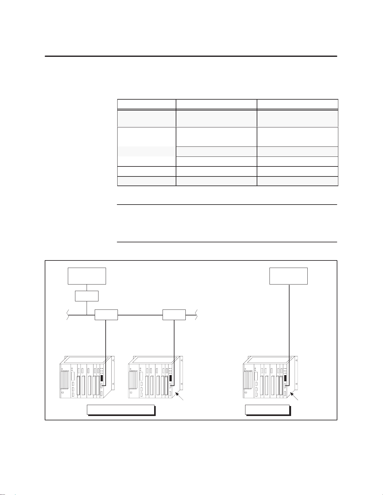
NOTE: On multidrop networks, the MODNIM requires a commercial modem
to connect to the Modbus network, as shown in Figure 1-1. The MODNIM
connected to a Series 505 PLC is equivalent to the use of the Modicon J475
modem interface with a Modicon PLC.
Modbus host
Modem Modem
Multidrop
Modbus Network
Programmable
Configuration
Controllers
Figure 1-1 Multidrop
SIMATIC TI505/TI500 MODNIM User Manual
MODNIM
Point-to-point
and Point-to-point Configurations
Installation and Set-up
MODNIM
1-3

1.2 Quick Reference Installation Steps
General Requirements
Procedures
In
order to install and use the MODNIM module correctly
, you must meet
the following requirements.
•
Ensure that you have the appropriate MODNIM model.
•
The communications configurations of all devices attached to the
network must match; i.e., they must all have the same baud rate, stop
bits, parity
, handshaking, and transmission mode (ASCII or RTU).
Figure 1-2 provides a quick reference list of the basic steps for installing the
MODNIM.
Install power and I/O cabling.
Disconnect power to the I/O base.
Set configuration dipswitches.
Insert
module into selected I/O slot (Series 505) or two adjacent slots (Series 500).
Power up the I/O base.
Check MODNIM indicator lights.
V
erify MODNIM is logged into PLC.
Connect network cables.
Figure 1-2 Quick
Refer
ence Installation Pr
ocedures
1-4
Installation and Set-up
SIMATIC TI505/TI500 MODNIM User Manual

Handling the Module
Many
integrated circuit (IC) devices are susceptible to damage by the
discharge of static electricity
. Follow the suggestions listed below to reduce
the probability of damage to these devices when you are handling this
Network Interface module, the PLC, a base controller
, or any of the I/O
modules.
Both the module and the person handling the module should be at the same
ground potential. Also, follow these guidelines.
• T
ransport the module in an anti-static container or antistatic material.
•
Ensure that the work area has a conductive pad with a lead connecting
it to a common ground.
•
Ground yourself by making contact with the conductive pad and/or by
wearing a grounded wrist strap.
Inspecting the Module
Getting Started with Configuration and Installation
Inspect the module for any visible damage before setting any selectable
features. If damage is detected, contact your distributor or sales office for
further instructions.
The following sections describe the procedures for configuring the module,
installing the module in the base, connecting the communications cables to
the MODNIM, and initializing the system for operation. Before installing
the MODNIM, make sure that the PLC is installed and the programming
device is connected to the system.
SIMATIC TI505/TI500 MODNIM User Manual
Installation and Set-up
1-5

1.3 Setting the Dipswitches
Dipswitch Functions
Setting the Network Address
The
MODNIM module has two blocks of dipswitches.
•
The block of 8 dipswitches is used to select the MODNIM’s address on
the network.
•
The block of 10 dipswitches is used to configure the network
communications parameters.
NOTE:
following a power-up or RESET
The configuration and address switch settings are read only once
. Be sure to reset the MODNIM following
any change in dipswitch settings or PLC memory configuration. In addition,
be aware that when the MODNIM is reset, no communication can occur
from the host to the module for several seconds.
Each node on a Modbus network must have a unique address. The range of
valid addresses is 1 to
247
(0000 0001 to 1111 0111). The address is set in
binary numbers using the block of 8 dipswitches.
NOTE:
invalid addresses and, if selected, cause the module to go into T
Addresses 0 or 248 to 255 (0000 0000 or 1111 1000 to 1111 1111) are
est mode.
Figure 1-3 shows examples of network addresses and their corresponding
dipswitch settings. (W
ith the Series 505 MODNIM, hold the module with
the faceplate pointing upward, as shown in Figure 1-5. For the Series 500
MODNIM, refer to Figure 1-6 for dipswitch orientation.)
Bit
Weight
Address
(0000
1
2
4
8
16
32
64
128
01
1
0001)
12345678
00000001
Represents direction to slide a sliding-type switch, or
=
side of switch to press down on a rocker-type switch
on Series 505 MODNIM.
Figure 1-3 Address
Address
(0001 1001)
1
2
4
8
16
32
64
128
01
25
12345678
00011001
Setting Examples
Address
(1
100 101
1
2
4
8
16
32
64
128
01
203
1)
12345678
11001011
1-6
Installation and Set-up
SIMATIC TI505/TI500 MODNIM User Manual

Selecting Network Configuration Parameters
The
block of 10 dipswitches is used to configure the network communication
parameters, which include data transmission rate, stopbit selection, parity
transmission mode, RTS/CTS handshaking, and output coil mapping.
(NOTE:
For all Series 500 MODNIM dipswitch settings, see Figure 1-6.)
,
Data T
ransmission
Rate
Stopbit Selection
Switches 1 through 4 are used to set the data transmission rate. All devices
on the network must be configured to communicate at the same data rate.
Switch settings for each of the available data rates are shown in Figure 1-4.
Network
Configuration
Dipswitches
10
9
8
7
6
5
4
3
2
1
For
Series 505:
For Series 500:
10
01
Figure 1-4 Dipswitch
Data
Rate
Settings for Network Data T
Switches
1234 Baud
0000 – 50
0001 – 50
0010 – 75
0011 – 110
0100 – 150
0101 – 200
0110 – 300
0111 – 600
1000 –1200
1001 –1800
1010 –2400
1011 –3600
1100 –4800
1101 –7200
1110 –9600
1111 –19200
ransmission Rates
Switch 5 is used to select 1 or 2 stopbits. Set switch to the left for 1 stopbit,
to the right for 2 stopbits (on Series 505; for Series 500, see Figure 1-6).
Parity/No Parity Selection
Switch 6 is used to select Parity or No Parity when communicating over an
RS-232-C data link. T
whether you need odd or even parity and set switch 7 accordingly
Odd/Even Parity Selection
ASCII/R
TU Mode
Selection
RTS/CTS Handshaking
If you selected Parity with switch 6, then you must also select either Odd or
Even Parity using switch 7. This switch is active only if switch 6 is set to
Parity
. Set switch to the left for Even parity
Switch 8 is used to select ASCII or RTU mode of transmission. Slide switch
to the left for ASCII mode, to the right for RTU mode.
Switch 9 is used to enable or disable RTS/CTS handshaking. If you are
using point-to-point connections without using modems, you can disable
RTS/CTS handshaking by setting switch 9 to the left. Set switch 9 to the
right to select RTS/CTS handshaking for use with modems.
Y/C Coil Selection
Switch 10 is used to determine whether the MODNIM collects data from the
PLC’
s Discrete Output (Y) memory or the Control Relay (C) memory
switch to the left for C coils, to the right for Y outputs.
SIMATIC TI505/TI500 MODNIM User Manual
o select Parity
, set switch to the left, then determine
.
, to the right for Odd parity
.
. Set
Installation and Set-up
1-7
Setting the Dipswitches (continued)
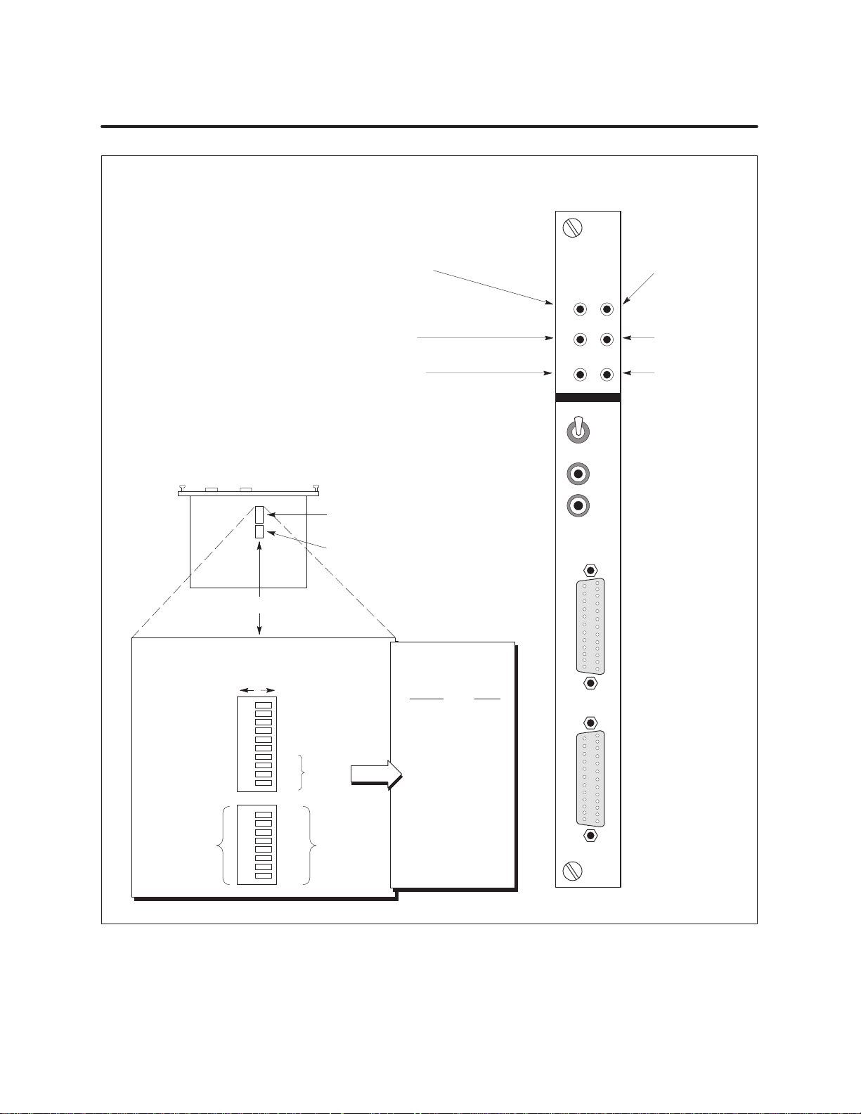
NIM GOOD —
Base power and
MODNIM operating status
XMT —
Data T
ON LINE —
Connected to the Modbus network.
Continuous
flashing
ransmit indicator
ON indicates
indicates
local
remote
mode
Series
mode;
505 MODNIM
MODNIM
NIM
GOODPCGOOD
XMT REC
ON
LINE TEST
REMOTE
PC GOOD —
PLC/MODNIM
communication
link status
REC —
Receiving Data
indicator
TEST —
T
est mode status
Side V
Faceplate Up
Dipswitch
Push
Down
Left
C COILS
RTS/CTS: OFF
ASCII MODE
PARITY: EVEN
PARITY
: ON
STOPBITS: 1
0
iew of Module,
Dipswitches
Settings
Push Down
Right
9
8
7
6
5
4
3
2
1
8
7
6
5
4
3
2
1
Y OUTPUT
RTS/CTS: ON
RTU MODE
PARITY: ODD
PARITY
STOPBITS: 2
1
1
1
1
1
2
4
8
16
32
64
128
10
0
0
0
0
Network
Configuration
Network
Address
: OFF
DATA
RATE
SELECT
Network
Address
Data Transmission
Rate Settings
Switches
1 2 3 4
0
0 0 0
0 0 0 1
0 0 1 0
0 0 1 1
0 1 0 0
0 1 0 1
0 1 1 0
0 1 1 1
1 0 0 0
1 0 0 1
1 0 1 0
1 0 1 1
1 1 0 0
1 1 0 1
1 1 1 0
1 1 1 1
Baud
–50
–50
–75
–110
– 150
– 200
– 300
– 600
– 1200
– 1800
– 2400
– 3600
– 4800
– 7200
– 9600
– 19200
PORT
POR
505-5184
LOCAL
TEST
RESET
A
T B
1-8
Figure 1-5 Series
Installation and Set-up
505 MODNIM Switches and LEDs
SIMATIC TI505/TI500 MODNIM User Manual
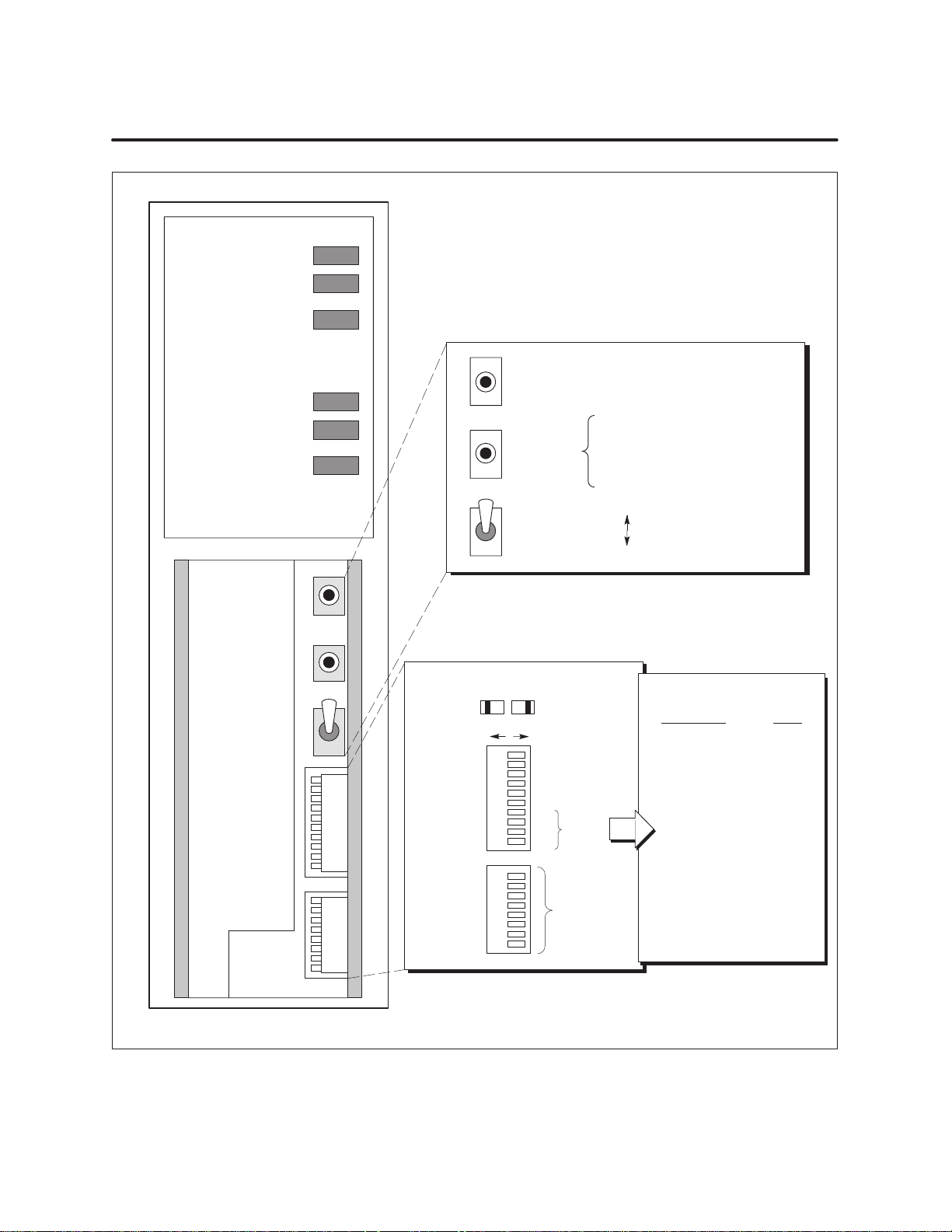
Series
500 MODNIM
NIM GOOD
PC/NIM COMM GOOD
ONLINE
RECEIVE
TRANSMIT
TEST MODE
Local/Remote
Configuration
Switches
Switches
Reset
Self-Test
Network
Address
DIPSWITCH
Y OUTPUTS
RTS/CTS: ON
RTU MODE
PARITY: ODD
PARITY
STOPBITS: 2
Network
Address
: OFF
128
10
9
8
7
6
5
4
1
3
1
2
1
1
1
8
1
7
2
6
4
5
8
4
16
3
32
2
64
1
Reset
Self-Test
Local/Remote
Settings
01
C COILS
RTS/CTS: OFF
ASCII MODE
PARITY: EVEN
PARITY
: ON
STOPBITS: 1
0
DATA
0
RATE
0
SELECT
0
0
• Push
1. Select
2.
3.
4.
to reset
Local control
Remove network cables
Install Loopback connectors
Press Reset and Self-T
together and hold 5 seconds.
Remote control (on-line)
Local control (of
f-line)
Data Transmission Rates
Switches
1234 Baud
0000 – 50
0001 – 50
0010 – 75
0011 – 110
0100 – 150
0101 – 200
0110 – 300
0111 – 600
1000 –1200
1001 –1800
1010 –2400
1011 –3600
1100 –4800
1101 –7200
1110 –9600
1111 –19200
est
Figure 1-6 Series
SIMATIC TI505/TI500 MODNIM User Manual
500 MODNIM Switches and LEDs
Installation and Set-up
1-9

1.4 Installing the MODNIM
Installing the Series 505 MODNIM in the I/O Base
!
WARNING
To
install the Series 505 MODNIM in the selected slot of the I/O base, follow
these steps.
To
avoid the possibility of personal injury, damage to the module,
altering the PLC memory
power to the base’
s power supply and to any modules installed in
, or causing a PLC fatal error
, disconnect
the base before inserting or removing the MODNIM.
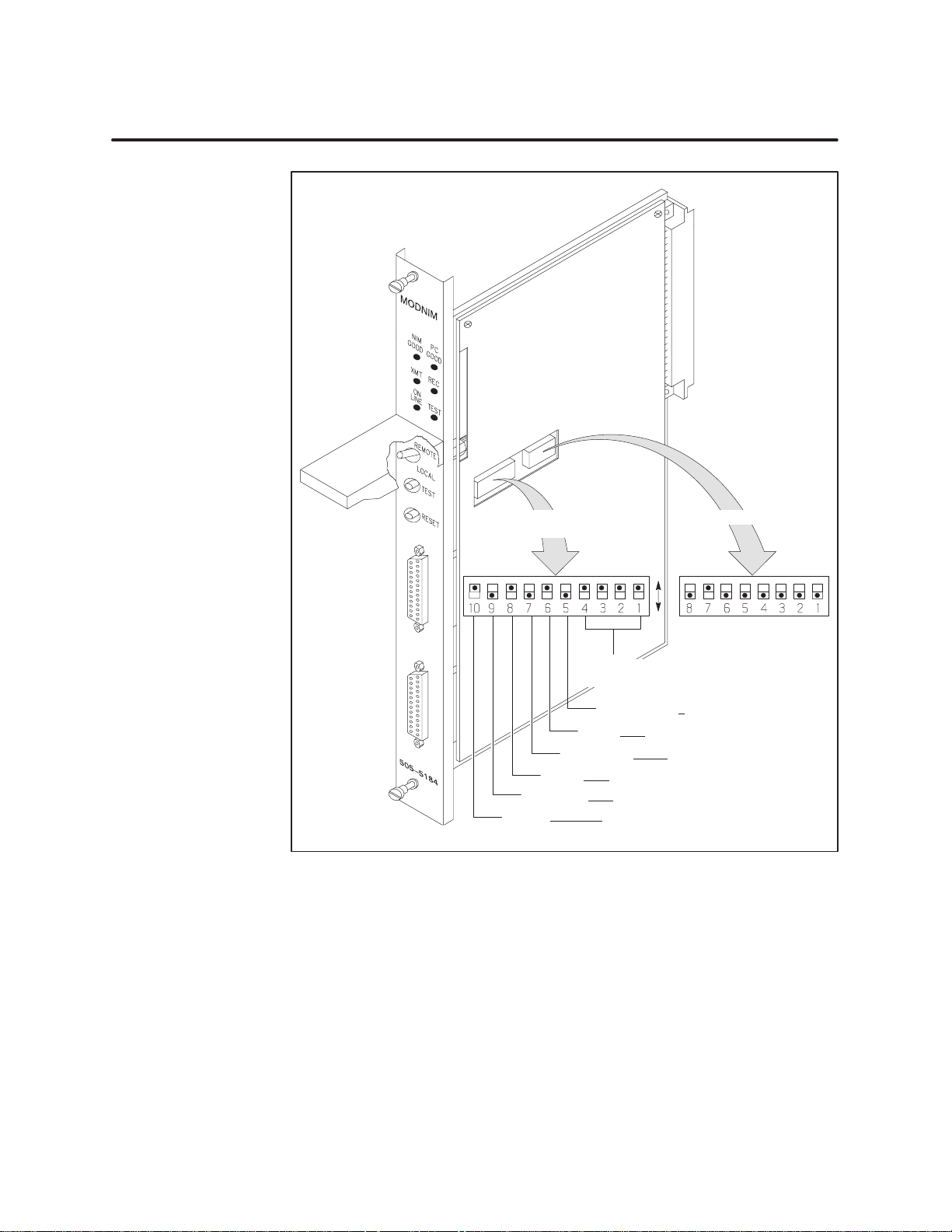
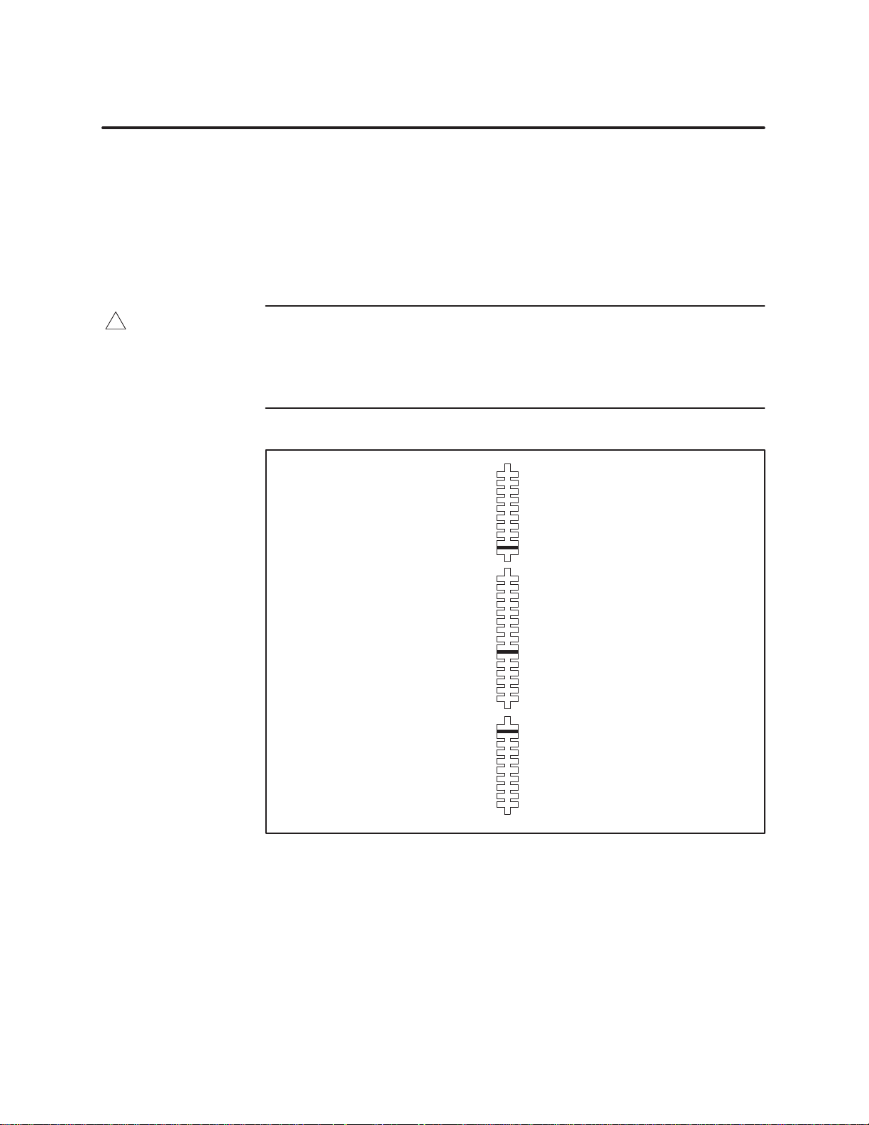
1. Disconnect
2.
Set the dipswitches, as described in Section 1.3. (See also Figure 1-8 for
power to the I/O base.
example dipswitch configuration settings.)
3.
Position the module so that the front bezel is facing you.
4.
Hold the top and bottom of the bezel and carefully slide the module into
the slot, pushing it all the way into the base connector
5.
Ensure that the edge card connector is firmly seated in the I/O base
. (See Figure 1-7.)
connector.
ighten the screws at the top and bottom of the faceplate with a flat-
6. T
bladed screwdriver
. (These screws also ground the module to the base.)
1-10
Installation and Set-up
Figure 1-7 Installing
Minimum
Maximum torque: 5.22 in-lb (0.6 N-m)
torque: 2.61 in-lb (0.3 N-m)
the Series 505 MODNIM in the I/O Base
SIMATIC TI505/TI500 MODNIM User Manual
Network
Configuration
Network Address
1 2 4 8 16 32 64 128
1
Figure 1-8 Series
Parity ODD/EVEN
Mode R
R
TS/CTS: OFF
C
coils/Y outputs
Baud Rate
(19200 shown)
Stop bits 2 or 1
Parity OFF
TU/ASCII
/ON
/ON
0
Network
address is
determined by the
sum of the values of
selected switches.
(Address
Note:
switch to press down.
2 shown)
D
= side of
505 MODNIM Example Dipswitch Settings
SIMATIC TI505/TI500 MODNIM User Manual
Installation and Set-up
1-11
Installing the MODNIM (continued)
Installing the Series 500 MODNIM in the I/O Base
!
WARNING
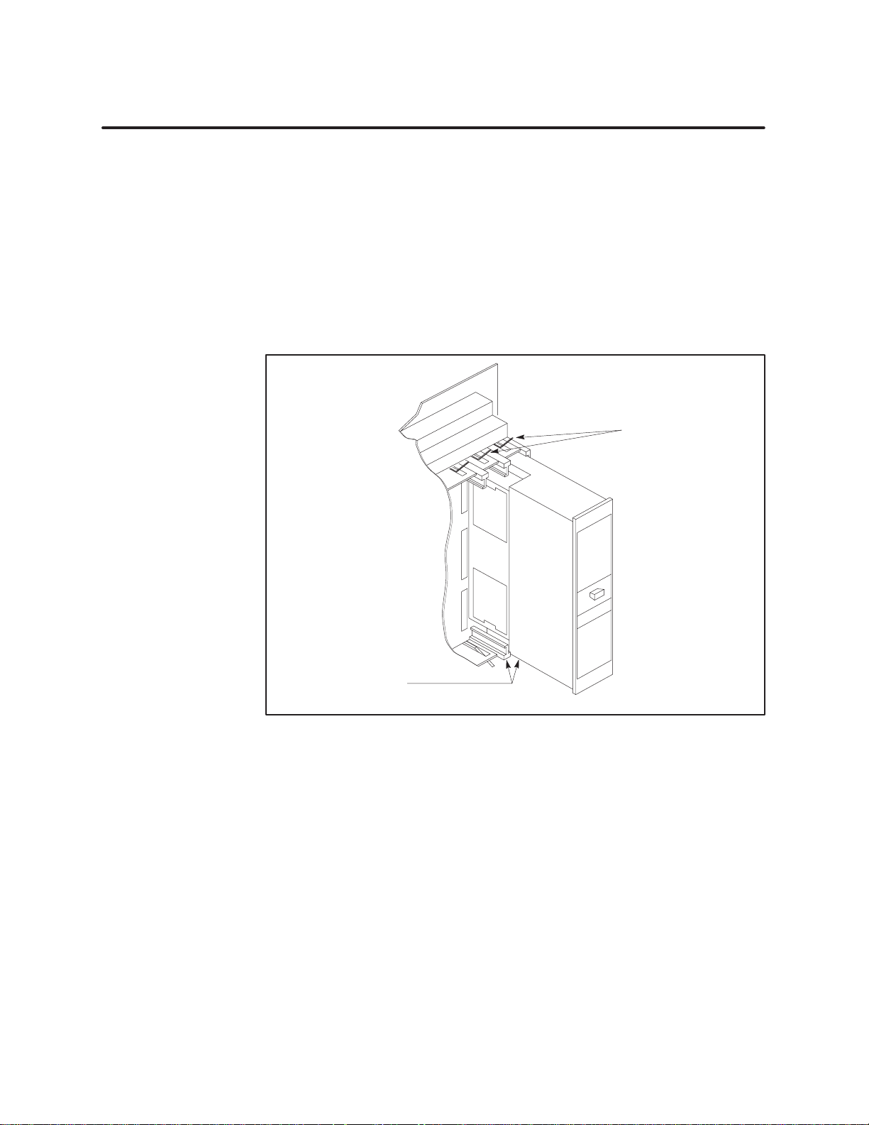
You
can key the Series 500 MODNIM module to prevent another I/O module
from being inserted by mistake into the two slots reserved for the MODNIM
module.
T
o do this, insert the three keys provided in the right slot of the two slots
occupied by the module so that they fit into the notches in the edge card of
the module. (See Figure 1-9.)
To
avoid the possibility of personal injury, damage to the module,
altering the PLC memory
power to the base’
the base before inserting or removing the MODNIM or the I/O slot
keys.
s power supply and to any modules installed in
, or causing a PLC fatal error
, disconnect
1-12
Installation and Set-up
Figure 1-9 Keying
the I/O Base Slot for the Series 500 MODNIM
SIMATIC TI505/TI500 MODNIM User Manual
Once
the I/O slot keys are in place, you can insert the module as follows.
1.
Set the dipswitches, described in Section 1.3.
2.
Position the module so that the front bezel is facing you.
3.
Hold the top and bottom of the bezel and carefully slide the module into
the slot, pushing it all the way into the base connector
. When the
module is fully seated in the I/O base, locking tabs will hold the module
in place. (See Figure 1-10.)
Locking
tabs
Locking tabs
Figure 1-10 Installing
4. T
o remove the module, pull the tabs away from the module and slide it
out of the base, being careful not to damage the edge card.
SIMATIC TI505/TI500 MODNIM User Manual
the Series 500 MODNIM in the I/O Base
Installation and Set-up
1-13

1.5 Switches and Indicator Lights
Switches and Buttons
Reset Button
The
three switches located on the face of the module behind the access door
are Reset, Self T
est, and Local/Remote, and are described in the following
paragraphs.
The Reset button is a momentary-contact switch which initializes the
MODNIM and initiates the power
-up self test. When you press Reset, all the
indicators turn on for approximately 1 second. Then, all indicators except
TEST go off for about 5 seconds. During this time, the MODNIM runs a
series of diagnostic tests to verify that the hardware components of the
module are operating properly
. In addition, buffers and counters that
service the Modbus Diagnostic Functions are initialized.
If the tests have been successfully completed, only the NIM GOOD and the
PC GOOD (PC/NIM COMM GOOD) indicators will turn back on, while the
TEST indicator turns off. If, however
the User Initiated Self-Test to determine the source of the error
NOTE:
Always press the Reset button after you change any of the
, the TEST indicator
remains on, run
.
configuration dipswitches or address selection dipswitches. In addition, be
aware that when the MODNIM is reset, no communication can occur from
the host to the module for several seconds.
T
est Button
Local/Remote Switch
The T
est button initiates a series of diagnostic tests when it is held down for
3 seconds after a Reset operation. Before running the diagnostic tests,
disconnect all communications cables and install loopback connectors on the
RS-232-C communications ports. These tests are described in more detail in
Section 1.6.
When set to Remote, this two-position toggle switch enables the MODNIM
to perform write operations to PLC memory
. In the Local position, the
MODNIM cannot write to the PLC.
In either position, the MODNIM can monitor PLC memory and mode of
operation. After the MODNIM is set to Online state, local or remote status
is indicated as follows.
• Local
• Remote
When set to Local mode, only the Read functions 1, 2, 3, 4, 7, 1
mode is indicated by a
mode is indicated by a
flashing
steady
ONLINE indicator
ONLINE indicator
.
.
1, 12, and 17
plus diagnostics function 8 can be performed. All other functions (write
operations) will be rejected with Exception Code 01.
1-14
Installation and Set-up
SIMATIC TI505/TI500 MODNIM User Manual
Status
Lights
Indicator
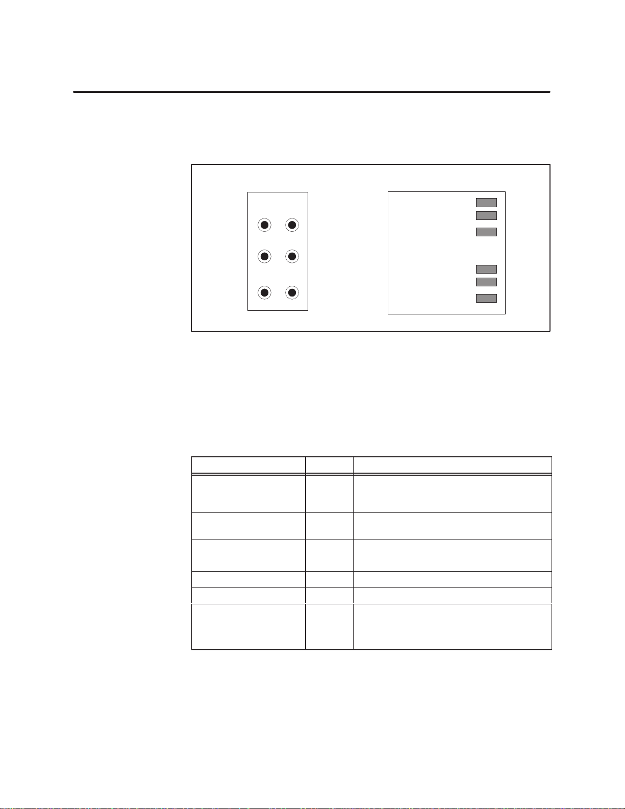
The
MODNIM has six indicator lights (or LEDs) located on the faceplate of
the module (see Figure 1-1
diagnostic status of the module as described below
Series 505 MODNIM
NIM
GOODPCGOOD
XMT REC
1). These lights indicate the operational or
.
Series
500 MODNIM
NIM
GOOD
PC/NIM COMM GOOD
ONLINE
ON
LINE TEST
Figure 1-11 Series
T
able 1-2 shows how to interpret the status of the six indicator lights on the
505 and 500 MODNIM Indicator Lights
RECEIVE
TRANSMIT
TEST MODE
faceplate of the MODNIM during normal operation. Section 1.6 describes
additional interpretations of the indicator lights during diagnostic testing.
T
able 1-2
Indicator Status Description
NIM GOOD On
PC/NIM COMM GOOD
(PC GOOD)
ONLINE
RECEIVE (REC) On Receiving data over the network
TRANSMIT (XMT) On Transmitting data over the network
TEST MODE (TEST)
Status of Indicator Lights
All power-on, reset, or run-time diagnostic
tests have been passed successfully;
MODNIM operating correctly.
On Communicating successfully with PLC
On
Flashing
On
On
Flashing
Connected to the network: Remote mode
Connected to the network: Local mode
MODNIM in Test mode
Failure detected after power-up diagnostics
Tests completed
SIMATIC TI505/TI500 MODNIM User Manual
Installation and Set-up
1-15

1.6 Diagnostic Tests
Built-in Diagnostic Tests
Power
-up Self T
est
The
MODNIM has the following three levels of self tests available.
• Power
•
• User
The MODNIM executes a Power
•
-up Self T
Run-time Self T
-initiated Self T
ests
ests
ests
-up Self T
est in the following cases.
Immediately after you apply +5 VDC power from the I/O base as part of
initialization.
•
Any time the Reset button is pressed.
The Power
-up Self T
est checks the processor and performs a test of on-board
RAM and ROM. At the start of the test, all MODNIM indicators are turned
on for approximately 1 second, then all except the TEST MODE indicator go
off for about 5 seconds.
If the Power
-up Self T
est is successful, the NIM GOOD light turns on, and
the MODNIM attempts to establish communications with the PLC. If this is
successful, the PC GOOD (PC/NIM COMM GOOD) light turns on and the
MODNIM is ready for normal network control (see Figure 1-12).
If the Power
-up Self T
est fails, the TEST MODE indicator remains on and
the MODNIM will not respond to any communication attempts.
If the PLC does not respond, the PC GOOD (PC/NIM COMM GOOD)
indicator remains off, and the MODNIM will issue an exception response
with Error Code 04 (failure in associated device) to any host computer
initiating an interactive request to this MODNIM. In addition, the TEST
MODE indicator flashes at a 3-second interval, remaining on for 1 second.
Reset
or
Power-up
NIM
GOODPCGOOD
XMT REC
ON
LINE
TEST
1 second
Figure 1-12 LED
NIM
GOODPCGOOD
XMT REC
ON
LINE
TEST
5 seconds
NIM
GOODPCGOOD
XMT REC
ON
LINE
Successful
internal tests
Status during Power
TEST
-Up Self T
NIM
GOODPCGOOD
XMT REC
ON
LINE
TEST
Communicating
with PLC
est
1-16
Installation and Set-up
SIMATIC TI505/TI500 MODNIM User Manual

Run-time Self T
ests
The
MODNIM monitors itself continuously during normal operation as
follows.
The operating system continuously performs a ROM integrity test as a
•
background process.
•
The MODNIM periodically verifies that it is capable of communicating
with the PLC.
•
A W
atchdog T
imer circuit in the MODNIM guards against software
lockup.
If any failures are detected in the ROM integrity test, the NIM GOOD
indicator light turns off and the MODNIM is forced into the failed state. In
this condition, the module goes into the Offline Mode and will not respond to
any requests. (See Figure 1-13.)
When the MODNIM is in its normal operating mode but fails to
communicate with the PLC, it reports this failure to the host computer with
an exception response. Error code 04 (failure in associated device) is sent,
and the PC GOOD (PC/NIM COMM GOOD) indicator goes out. (See
Figure 1-13.) If communication is re-established, the MODNIM returns to
normal mode and the PC GOOD indicator goes back on.
NOTE:
goes on and remains on as long as everything is operating properly
The W
The first time a valid request is received, the ON LINE indicator
.
NIM
GOODPCGOOD
XMT REC
ON
LINE
TEST
All Run-time
tests OK
Figure 1-13 LED
atchdog T
imer circuit provides an extra measure of protection against
NIM
GOODPCGOOD
XMT REC
ON
LINE
TEST
ROM
Integrity Failure:
goes to Offline Mode
Status during Normal Run-T
Not Communicating with
PLC: reports Error Code 04
NIM
GOODPCGOOD
XMT REC
ON
LINE
TEST
ime Operation
network lockup due to a failed MODNIM. This circuit will force a RESET if
the operating software fails to execute normally
.
SIMATIC TI505/TI500 MODNIM User Manual
Installation and Set-up
1-17
 Loading...