

Siemens SIMATIC TI500, SIMATIC TI505, PPX:500–7301, PPX:500–7302, PPX:500–7303 User Manual
...
SIMATIC TI500/TI505
TIWAY 1 Gateway
User Manual
Order Number PPX:TIWAY-8104-02
Manual Assembly Number: 2587871-0004
Second Edition

Copyright
1992 by Siemens Industrial Automation, Inc.
All Rights Reserved — Printed in USA
Reproduction,
contents is not permitted without express consent of
Siemens Industrial
created by patent grant or registration of a utility model or
design, are reserved.
Since Siemens Industrial Automation, Inc. does not possess
full access to data concerning all of the uses and applications
of customer’s products, we do not assume responsibility either
for customer product design or for any infringements of patents
or rights of others which may result from our assistance.
01/21/92
transmission or use of this document or
Automation, Inc. All rights, including rights
T
echnical data is subject to change.
W
e check the contents of every manual for accuracy at the
time it is approved for printing; however
undetected errors. Any errors found will be corrected in
subsequent editions. Any suggestions for improvement are
welcomed.
, there may be

MANUAL PUBLICA
TION HISTOR
Y
SIMATICTI500/TI505
Or
der Manual Number: PPX:TIW
Refer to this history in all correspondence and/or discussion about this manual.
Event Date Description
Original Issue
Second Edition
TIWAY I Gateway User Manual
AY–8104–2
09/85
09/92
Original Issue (2491964–0001)
Second Edition (2491964–0002)

LIST
OF EFFECTIVE P
Pages Description Pages Description
Cover/Copyright Second
History/Effective
iii — x
1-1 — 1-4
2-1 — 2-12 Second
3-1 — 3-14 Second
A-1 — A-4
B-1 — B-3
C-1 — C-28
D-1 — D-11
Index-1 — Index-3
Registration Second
Pages
AGES
Second
Second
Second
Second
Second
Second
Second
Second

Preface
Chapter 1 Product Overview
Contents
1.1 Introduction 1-2.
The
Gateway Inter
Distributed
1.2 Basic
Operating Featur
Interface
Translating
Data T
Types
ransmission Rates Supported
of Data Accessed
. . . . . . . . . . . . . . . . . . . . . . . . . . . . . . . . . . . . . . . . . . . . . . . . . . . . . . . . . . . . . . . . . . .
face 1-2.
Contr
ol Systems
Ports
. . . . . . . . . . . . . . . . . . . . . . . . . . . . . . . . . . . . . . . . . . . . . . . . . . . . . . . . . . . . . . . . .
Commands between Host and PLC Network
. . . . . . . . . . . . . . . . . . . . . . . . . . . . . . . . . . . . . . . . . . . . . . . . . . . . . . . .
. . . . . . . . . . . . . . . . . . . . . . . . . . . . . . . . . . . . . . . . . . . . . . . . . . . . .
es 1-3.
. . . . . . . . . . . . . . . . . . . . . . . . . . . . . . . . . . . . . . . . . . . . . . . . . . . . . . .
. . . . . . . . . . . . . . . . . . . . . . . . . . . . . . . . . . . . . . . . . . . . . . . . . . . . . . .
Chapter 2 Network Installation
2.1 TIWAY
2.2 Network
I Network and Gateway Installation Checklist
Quick
Refer
ence Installation Steps
Basic
Installation Pr
Requirements
Media Installation — Local Line
Overview 2-4
Local
TIWAY
Local
Tap
Housing
Terminating
Twisted-Pair
Important
Local
Basic
Primary
Double
Short
Multidrop Taps 2-9.
Cable
Obstructions 2-11
Noise Avoidance 2-11.
. . . . . . . . . . . . . . . . . . . . . . . . . . . . . . . . . . . . . . . . . . . . . . . . . . . . . . . . . . . . . . . . . . . . . . .
Line Cable Characteristics
I Network Characteristics
Line Har
the Main Line Cable
Cabling
Planning Considerations
Line T
ap Spacing Rules
Considerations
Rule
Dr
ops 2-9.
Dr
ops 2-9.
Routing
ocedures 2-3.
for Installing the Gateway
dwar
e Components
. . . . . . . . . . . . . . . . . . . . . . . . . . . . . . . . . . . . . . . . . . . . . . . . . . . . . . . . . . . . . . . . . . .
. . . . . . . . . . . . . . . . . . . . . . . . . . . . . . . . . . . . . . . . . . . . . . . . . . . . . . . . . . .
. . . . . . . . . . . . . . . . . . . . . . . . . . . . . . . . . . . . . . . . . . . . . . . . . . . . . . . . . . .
. . . . . . . . . . . . . . . . . . . . . . . . . . . . . . . . . . . . . . . . . . . . . . . . . . . . . . . . . . . . . . . . . . .
. . . . . . . . . . . . . . . . . . . . . . . . . . . . . . . . . . . . . . . . . . . . . . . . . . . . . . . . . . . . . . . . . .
. . . . . . . . . . . . . . . . . . . . . . . . . . . . . . . . . . . . . . . . . . . . . . . . . . . . . . . . . . . . . . . . . . . .
. . . . . . . . . . . . . . . . . . . . . . . . . . . . . . . . . . . . . . . . . . . . . . . . . . . . . . . . . . . . . . . . .
. . . . . . . . . . . . . . . . . . . . . . . . . . . . . . . . . . . . . . . . . . . . . . . . . . . . . . . . . . . . . . . . .
. . . . . . . . . . . . . . . . . . . . . . . . . . . . . . . . . . . . . . . . . . . . . . . . . . . . . . . . . . . . . . . . . . . .
. . . . . . . . . . . . . . . . . . . . . . . . . . . . . . . . . . . . . . . . . . . . . . . . . . . . . . . . . . . . . .
1-2.
1-3.
. . . . . . . . . . . . . . . . . . . . . . . . .
. . . . . . . . . . . . . . . . . . . . . . . . . . . . . . . . . . . . . . . . . . . . .
. . . . . . . . . . . . . . . . . . . . . . . . . . . . .
. . . . . . . . . . . . . . . . . . . . . . . . . . . . . . . . . . . . . . . . . . . . . .
. . . . . . . . . . . . . . . . . . . . . . . . . . . . . . . . . . . . . . . . . . . . . . . . . . . .
. . . . . . . . . . . . . . . . . . . . . . . . . . . . . . . . . . . . . . . .
. . . . . . . . . . . . . . . . . . . . . . . . . . . . . . . . . . . . . . . .
. . . . . . . . . . . . . . . . . . . . . . . . . . . . . . . . . . . . . . . . . . . . . . . .
. . . . . . . . . . . . . . . . . . . . . . . . . . . . . . . . . . . . . . . . . . . . . . . . .
. . . . . . . . . . . . . . . . . . . . . . . . . . . . . . . . . . . . . . . . . . . . . .
. . . . . . . . . . . . . . . . . . . . . . . . . . . . . . . . . . . . . . . . . . . . . . .
. . . . . . . . . . . . . . . . . . . . . . . . . . . . . . . . . . . . . . . . . . . . .
. . . . . . . . . . . . . . . . . . . . . . . . . . . . . . . . . . . . . . . . . . . . . . . . . . .
1-4.
1-4.
1-4.
2-2.
2-2.
2-3.
2-4.
2-4.
2-5.
2-6.
2-6.
2-7.
2-7.
2-7.
2-8.
2-8.
2-8.
2-10.
2.3 Network
Data T
RS-232
Media Installation — RS-232-C Modem Inter
ransmission Characteristics
Pin Assignments
face 2-12.
. . . . . . . . . . . . . . . . . . . . . . . .
. . . . . . . . . . . . . . . . . . . . . . . . . . . . . . . . . . . . . . . . . . . . . . .
. . . . . . . . . . . . . . . . . . . . . . . . . . . . . . . . . . . . . . . . . . . . . . . . . . . . . . . . .
Contents iii
2-12.
2-12.

Chapter 3 Gateway Installation and Configuration
3.1 Installing
Basic
Power
3.2 Dipswitch
Overview 3-6
Dipswitch
Dipswitch
3.3 Switches
Online/Offline
Self-Test
Reset
Status
Gateway
Comm
Online 3-11
Receive 3-11
Transmit 3-11
Test
3.4 Diagnostic Tests 3-12.
Built-In
Power-On Test 3-12.
Operational
User-Initiated Test 3-13.
Burn-In
the TIWAY I Gateway
Mounting Guidelines
Connections and Initialization
Configuration and Function
. . . . . . . . . . . . . . . . . . . . . . . . . . . . . . . . . . . . . . . . . . . . . . . . . . . . . . . . . . . . . . . . . . . . . . .
Settings for the Host Inter
Settings for the Network Interface Port
and Indicator Lights
Switch
Button
Button
Indicator Lights
Active
. . . . . . . . . . . . . . . . . . . . . . . . . . . . . . . . . . . . . . . . . . . . . . . . . . . . . . . . . . . . . . . . . . . . . . . . . .
Mode
Diagnostic T
and Final T
. . . . . . . . . . . . . . . . . . . . . . . . . . . . . . . . . . . . . . . . . . . . . . . . . . . . . . . . . . . . . . . . . . .
Good
. . . . . . . . . . . . . . . . . . . . . . . . . . . . . . . . . . . . . . . . . . . . . . . . . . . . . . . . . . . . . . . . . . . . . . . .
. . . . . . . . . . . . . . . . . . . . . . . . . . . . . . . . . . . . . . . . . . . . . . . . . . . . . . . . . . . . . . . . . . . . . . . .
. . . . . . . . . . . . . . . . . . . . . . . . . . . . . . . . . . . . . . . . . . . . . . . . . . . . . . . . . . . . . . . . . . . . .
Diagnostic T
. . . . . . . . . . . . . . . . . . . . . . . . . . . . . . . . . . . . . . . . . . . . . . . . . .
. . . . . . . . . . . . . . . . . . . . . . . . . . . . . . . . . . . . . . . . . . . . . . . . . . . . .
. . . . . . . . . . . . . . . . . . . . . . . . . . . . . . . . . . . . . . . . . . . .
. . . . . . . . . . . . . . . . . . . . . . . . . . . . . . . . . . . . . . . . . . .
face Port
. . . . . . . . . . . . . . . . . . . . . . . . . . . . . . . . . . . . . . . . . . . . . . . . . . .
. . . . . . . . . . . . . . . . . . . . . . . . . . . . . . . . . . . . . . . . . . . . . . . . . . . . . . . . . . .
. . . . . . . . . . . . . . . . . . . . . . . . . . . . . . . . . . . . . . . . . . . . . . . . . . . . . . . . . . . . . . . .
. . . . . . . . . . . . . . . . . . . . . . . . . . . . . . . . . . . . . . . . . . . . . . . . . . . . . . . . . .
. . . . . . . . . . . . . . . . . . . . . . . . . . . . . . . . . . . . . . . . . . . . . . . . . . . . . . . . . . . . . . .
. . . . . . . . . . . . . . . . . . . . . . . . . . . . . . . . . . . . . . . . . . . . . . . . . . . . . . . . . . . . . . . . .
. . . . . . . . . . . . . . . . . . . . . . . . . . . . . . . . . . . . . . . . . . . . . . . . . . . . . . . . . . . . . . . .
ests 3-12.
. . . . . . . . . . . . . . . . . . . . . . . . . . . . . . . . . . . . . . . . . . . . . . . . . . . . . . . . .
. . . . . . . . . . . . . . . . . . . . . . . . . . . . . . . . . . . . . . . . . . . . . . . . . . . . . . . . . . . . . . . . .
est 3-12.
. . . . . . . . . . . . . . . . . . . . . . . . . . . . . . . . . . . . . . . . . . . . . . . . . . . .
. . . . . . . . . . . . . . . . . . . . . . . . . . . . . . . . . . . . . . . . . . . . . . . . . . . . . . . . . . . . . .
ests 3-14.
. . . . . . . . . . . . . . . . . . . . . . . . . . . . . . . . . . . . . . . . . . . . . . . . . . . . . . . . . .
. . . . . . . . . . . . . . . . . . . . . . . . . . . . . . . . . . . .
. . . . . . . . . . . . . . . . . . . . . . . . . . . . . . . .
3-2.
3-2.
3-3.
3-6.
3-7.
3-8.
3-10.
3-10.
3-10.
3-10.
3-11.
3-11.
3-11.
3-11.
Appendix A Data Type Identification
A.1 Corresponding
A.2 SIMATIC
A.3 TIWAY
Appendix
B.1 System
B.2 V-Memory
iv Contents
TI PLCs Supported by TIWAY I Gateway
I Gateway Specifications
B
Configuration
Data T
ypes A-2.
. . . . . . . . . . . . . . . . . . . . . . . . . . . . . . . . . . . . . . . . . . . . . . . . . . . . .
. . . . . . . . . . . . . . . . . . . . . . . . . . . . . . . . . . . . . . . . . . . . . . . . .
System Configuration Forms
. . . . . . . . . . . . . . . . . . . . . . . . . . . . . . . . . . . . . . . . . . . . . . . . . . . . . . . . . .
Of
fset T
ables B-3.
. . . . . . . . . . . . . . . . . . . . . . . . . . . . . . . . . . . . . . . . . . . . . . . . . . . . . . . .
. . . . . . . . . . . . . . . . . . . . . . . . . . . . . . . . . .
A-3.
A-4.
B-2.

Appendix
C
Modbus Commands
C.1 Modbus
The R
TU T
Message
The
Addr
The
Function Field
The
Data Field
Checksum C-3
Invalid
Modbus
Addressing C-5
Address
C.2 Modbus
Introduction C-6
Code
01 — Read Coil Status
Code
02 — Read Input Status
Code
03 — Read Output Registers
Code
04 — Read Input Registers
Code 05 — W
Code 06 — W
Code
07 — Read Exception Status
Code
08 — Execute Diagnostics
Code
11 — Get Comms Event Counter
Code
12 — Get Comms Event Log
Code 15 — W
Code 16 — W
Pr
otocol Overview
ransmission Frame
Delineation
ess Field
. . . . . . . . . . . . . . . . . . . . . . . . . . . . . . . . . . . . . . . . . . . . . . . . . . . . . . . . . . . . . . . . . . . . .
Characters and Messages
Functions
. . . . . . . . . . . . . . . . . . . . . . . . . . . . . . . . . . . . . . . . . . . . . . . . . . . . . . . . . . . . . . . . . . . . .
Limits
Function Descriptions
. . . . . . . . . . . . . . . . . . . . . . . . . . . . . . . . . . . . . . . . . . . . . . . . . . . . . . . . . . . . . .
. . . . . . . . . . . . . . . . . . . . . . . . . . . . . . . . . . . . . . . . . . . . . . . . . . . . . . . . . . . . . .
. . . . . . . . . . . . . . . . . . . . . . . . . . . . . . . . . . . . . . . . . . . . . . . . . . . . . . . . . . . . . . . . .
. . . . . . . . . . . . . . . . . . . . . . . . . . . . . . . . . . . . . . . . . . . . . . . . . . . . . . . . . . . . .
. . . . . . . . . . . . . . . . . . . . . . . . . . . . . . . . . . . . . . . . . . . . . . . . . . . . . . . . . . . . . . . . . .
. . . . . . . . . . . . . . . . . . . . . . . . . . . . . . . . . . . . . . . . . . . . . . . . . . . . . . . . . . . . . . . . . . . .
rite a Single Coil
rite a Single Register
rite Multiple Coils
rite Multiple Registers
. . . . . . . . . . . . . . . . . . . . . . . . . . . . . . . . . . . . . . . . . . . . . . . . . . . . .
. . . . . . . . . . . . . . . . . . . . . . . . . . . . . . . . . . . . . . . . . . . . . . . . . . . . .
. . . . . . . . . . . . . . . . . . . . . . . . . . . . . . . . . . . . . . . . . . . . . . . . . . . . . . . . . .
. . . . . . . . . . . . . . . . . . . . . . . . . . . . . . . . . . . . . . . . . . . . . . .
. . . . . . . . . . . . . . . . . . . . . . . . . . . . . . . . . . . . . . . . . . . . . . . . . .
. . . . . . . . . . . . . . . . . . . . . . . . . . . . . . . . . . . . . . . . . . . . . . . . . . .
. . . . . . . . . . . . . . . . . . . . . . . . . . . . . . . . . . . . . . . . . . . . . . . . . .
. . . . . . . . . . . . . . . . . . . . . . . . . . . . . . . . . . . . . . . . . . . . . .
. . . . . . . . . . . . . . . . . . . . . . . . . . . . . . . . . . . . . . . . . . . . . . . .
. . . . . . . . . . . . . . . . . . . . . . . . . . . . . . . . . . . . . . . . . . . . . . . . . .
. . . . . . . . . . . . . . . . . . . . . . . . . . . . . . . . . . . . . . . . . . . . . .
. . . . . . . . . . . . . . . . . . . . . . . . . . . . . . . . . . . . . . . . . . . . . .
. . . . . . . . . . . . . . . . . . . . . . . . . . . . . . . . . . . . . . . . . . . . . . . .
. . . . . . . . . . . . . . . . . . . . . . . . . . . . . . . . . . . . . . . . .
. . . . . . . . . . . . . . . . . . . . . . . . . . . . . . . . . . . . . . . . . . . . .
. . . . . . . . . . . . . . . . . . . . . . . . . . . . . . . . . . . . . . . . . . . . . . . . .
. . . . . . . . . . . . . . . . . . . . . . . . . . . . . . . . . . . . . . . . . . . . .
C-2.
C-2.
C-3.
C-3.
C-3.
C-3.
C-4.
C-4.
C-5.
C-6.
C-6.
C-8.
C-10.
C-11.
C-12.
C-14.
C-15.
C-17.
C-20.
C-21.
C-23.
C-25.
C.3 User-Defined
Command
Command
Command
C.4 Error
Appendix
D.1 Considerations
D.2 PLC
D.3 PLC
Responses
D
PLC
Configuration Requir
Network
Programming Considerations
Blocking
Writing
Writing
PLC
Status Register
Pr
ogramming Example
Data
to be Accessed
Relay
Ladder Logic Pr
Modbus Commands
65 — Read C Memory
66 — Read K Memory
67 — Read WY Memory
Configuring the PLC for Fisher PROVOX
Design Considerations
Network Data
to Integer Registers
to Discr
. . . . . . . . . . . . . . . . . . . . . . . . . . . . . . . . . . . . . . . . . . . . . .
. . . . . . . . . . . . . . . . . . . . . . . . . . . . . . . . . . . . . . . . . . . . . .
. . . . . . . . . . . . . . . . . . . . . . . . . . . . . . . . . . . . . . . . . . . . . . .
. . . . . . . . . . . . . . . . . . . . . . . . . . . . . . . . . . . . . . . . . . . . .
. . . . . . . . . . . . . . . . . . . . . . . . . . . . . . . . . . . . . . . . . . . . . . . . . . . . . . . . . . . . . . . .
for Configuring a TIWAY I/PROVOX System
ements D-2.
. . . . . . . . . . . . . . . . . . . . . . . . . . . . . . . . . . . . . . . . . . . . . . . . . . . . . . . . .
ete Points
. . . . . . . . . . . . . . . . . . . . . . . . . . . . . . . . . . . . . . . . . . . . . . . . . . . . . . .
. . . . . . . . . . . . . . . . . . . . . . . . . . . . . . . . . . . . . . . . . . . . . . . . . . . . . . . . . . . . .
. . . . . . . . . . . . . . . . . . . . . . . . . . . . . . . . . . . . . . . . . . . . . . . . . . . . . . . . . .
ogram D-5.
. . . . . . . . . . . . . . . . . . . . . . . . . . . . . . . . . . . . . . . . . . . . . . .
. . . . . . . . . . . . . . . . . . . . . . . . . . . . . . . . . . . . . . . . . . . . . . . . .
. . . . . . . . . . . . . . . . . . . . . . . . . . . . . . . . . . . . . . . . . . . . . . .
. . . . . . . . . . . . . . . . . . . . . . . . . . . . . . . . . . . . . . . . . . . . . . . . . . . . .
. . . . . . . . . . . . . . . . . . . . . . . . . . . . . . . . . . . . . . . . . . . . . . . . . . . . .
. . . . . . . . . . . . . . . . . . . . . . . . . . . . . . . . . . . . . . . . . . . . . . . . . . .
. . . . . . . . . . . . . . . . . . . . . . . .
Contents v
C-26.
C-26.
C-27.
C-27.
C-28.
D-2.
D-2.
D-3.
D-3.
D-3.
D-3.
D-3.
D-4.
D-4.

List of Figures
1-1 TIWAY
1-2 TIWAY
2-1 Basic
2-2 Number
2-3 TIWAY I T
I Gateway as Inter
I Gateway
Installation and Set-up Steps
of Local Line Secondaries vs. Cable Distance
ap Housing
2-4 Terminating
2-5 Basic T
ap Spacing Rules
2-6 Additional T
3-1 Possible
3-2 AC
3-3 Dipswitch
3-4 Dipswitch
3-5 Gateway
3-6 Indicator
3-7 Indicator
C-1 RTU T
C-2 Bit
C-3 Read
C-4 Read
C-5 Read
C-6 Read
C-7 Read
C-8 Read
C-9 Read
C-10 Read
C-11 Read
C-12 Read
C-13 Write
C-14 Read
C-15 Write
C-16 Write
C-17 Read
C-18 Read
C-19 Exception
C-20 Execute
C-21 Execute
C-22 Get
C-23 Get
C-24 Get
C-25 Get
Bracket Locations for Mounting Gateway
Power Connections
Settings for the Network and Host Ports
Settings for Network Data T
Operation Switches
Lights
Status
ransmission Frame
Orientation
Coil Status Example — Request
Coil Status Example — Response
Coil Status Example — Data Field
Input Status Example — Request
Input Status Example — Response
Input Status Example — Data Field
Output Register Example — Request
Output Register Example — Response
Input Register Example — Request
Input Register Example — Response
a Single Coil Example — Request
Input Register Example — Response
a Single Register Example — Request
a Single Register Example — Response
Exception Status Example — Request
Exception Status Example — Response
Status Bits
Diagnostics Example — Request
Diagnostics Example — Response
Comms Event Counter Example — Request
Comms Event Counter Example — Response
Comms Event Log Example — Request
Comms Event Log Example — Response
face Between PLC Network and Host System
. . . . . . . . . . . .
. . . . . . . . . . . . . . . . . . . . . . . . . . . . . . . . . . . . . . . . . . . . . . . . . . . . . . . . . . . . . . .
. . . . . . . . . . . . . . . . . . . . . . . . . . . . . . . . . . . . . . . . . . . . . .
. . . . . . . . . . . . . . . . . . . . . . . . . . .
. . . . . . . . . . . . . . . . . . . . . . . . . . . . . . . . . . . . . . . . . . . . . . . . . . . . . . . . . . . .
the Local Line
. . . . . . . . . . . . . . . . . . . . . . . . . . . . . . . . . . . . . . . . . . . . . . . . . . . . . .
. . . . . . . . . . . . . . . . . . . . . . . . . . . . . . . . . . . . . . . . . . . . . . . . . . . . . . . .
ap Spacing Rules
. . . . . . . . . . . . . . . . . . . . . . . . . . . . . . . . . . . . . . . . . . . . . . . . . . .
. . . . . . . . . . . . . . . . . . . . . . . . . . . . . . .
. . . . . . . . . . . . . . . . . . . . . . . . . . . . . . . . . . . . . . . . . . . . . . . . . . . . . . . .
. . . . . . . . . . . . . . . . . . . . . . . . . . . . . . . .
ransmission Rates
. . . . . . . . . . . . . . . . . . . . . . . . . .
. . . . . . . . . . . . . . . . . . . . . . . . . . . . . . . . . . . . . . . . . . . . . . . . . .
. . . . . . . . . . . . . . . . . . . . . . . . . . . . . . . . . . . . . . . . . . . . . . . . . . . . . . . . . . . . . . . .
. . . . . . . . . . . . . . . . . . . . . . . . . . . . . . . . . . . . . . . . . . . . . . . . . . . . . . . . . . . . . . . .
. . . . . . . . . . . . . . . . . . . . . . . . . . . . . . . . . . . . . . . . . . . . . . . . . . . . . . . . .
. . . . . . . . . . . . . . . . . . . . . . . . . . . . . . . . . . . . . . . . . . . . . . . . . . . . . . . . . . . . . . . . .
. . . . . . . . . . . . . . . . . . . . . . . . . . . . . . . . . . . . . . . . . . .
. . . . . . . . . . . . . . . . . . . . . . . . . . . . . . . . . . . . . . . . . .
. . . . . . . . . . . . . . . . . . . . . . . . . . . . . . . . . . . . . . . . .
. . . . . . . . . . . . . . . . . . . . . . . . . . . . . . . . . . . . . . . . . .
. . . . . . . . . . . . . . . . . . . . . . . . . . . . . . . . . . . . . . . . .
. . . . . . . . . . . . . . . . . . . . . . . . . . . . . . . . . . . . . . . .
. . . . . . . . . . . . . . . . . . . . . . . . . . . . . . . . . . . . . .
. . . . . . . . . . . . . . . . . . . . . . . . . . . . . . . . . . . . .
. . . . . . . . . . . . . . . . . . . . . . . . . . . . . . . . . . . . . . . .
. . . . . . . . . . . . . . . . . . . . . . . . . . . . . . . . . . . . . . .
. . . . . . . . . . . . . . . . . . . . . . . . . . . . . . . . . . . . . . . . . .
. . . . . . . . . . . . . . . . . . . . . . . . . . . . . . . . . . . . . . .
. . . . . . . . . . . . . . . . . . . . . . . . . . . . . . . . . . . . . .
. . . . . . . . . . . . . . . . . . . . . . . . . . . . . . . . . . . .
. . . . . . . . . . . . . . . . . . . . . . . . . . . . . . . . . . . . .
. . . . . . . . . . . . . . . . . . . . . . . . . . . . . . . . . . . .
. . . . . . . . . . . . . . . . . . . . . . . . . . . . . . . . . . . . . . . . . . . . . . . . . . . . . . . . . . .
. . . . . . . . . . . . . . . . . . . . . . . . . . . . . . . . . . . . . . . .
. . . . . . . . . . . . . . . . . . . . . . . . . . . . . . . . . . . . . .
. . . . . . . . . . . . . . . . . . . . . . . . . . . . . . . . .
. . . . . . . . . . . . . . . . . . . . . . . . . . . . . . .
. . . . . . . . . . . . . . . . . . . . . . . . . . . . . . . . . . . . .
. . . . . . . . . . . . . . . . . . . . . . . . . . . . . . . . . . . .
1-2.
1-3.
2-2.
2-5.
2-6.
2-7.
2-8.
2-9.
3-2.
3-3.
3-5.
3-8.
3-10.
3-11.
3-14.
C-2.
C-4.
C-6.
C-7.
C-7.
C-8.
C-8.
C-9.
C-10.
C-10.
C-11.
C-11.
C-12.
C-13.
C-14.
C-14.
C-15.
C-15.
C-16.
C-17.
C-17.
C-20.
C-20.
C-21.
C-21.
vi Contents

C-26 Write
C-27 Coil
C-28 Write
C-29 Write
C-30 Write
Multiple Coils Example — Request
Bit Patter
Multiple Coils Example — Response
Multiple Registers Example — Request
Multiple Registers Example — Response
C-31 Command
C-32 Command
C-33 Command
C-34 Command
C-35 Command
C-36 Command
C-37 Exception
. . . . . . . . . . . . . . . . . . . . . . . . . . . . . . . . . . . . . . . . .
n C-23.
. . . . . . . . . . . . . . . . . . . . . . . . . . . . . . . . . . . . . . . . . . . . . . . . . . . . . . . . . . . . . . . . .
. . . . . . . . . . . . . . . . . . . . . . . . . . . . . . . . . . . . . . .
. . . . . . . . . . . . . . . . . . . . . . . . . . . . . . . . . . . . .
. . . . . . . . . . . . . . . . . . . . . . . . . . . . . . . . . . . .
65 — Request
65 — Response
66 — Request
66 — Response
67 — Request
67 — Response
Response Frame
. . . . . . . . . . . . . . . . . . . . . . . . . . . . . . . . . . . . . . . . . . . . . . . . . . . . . .
. . . . . . . . . . . . . . . . . . . . . . . . . . . . . . . . . . . . . . . . . . . . . . . . . . . . .
. . . . . . . . . . . . . . . . . . . . . . . . . . . . . . . . . . . . . . . . . . . . . . . . . . . . . .
. . . . . . . . . . . . . . . . . . . . . . . . . . . . . . . . . . . . . . . . . . . . . . . . . . . . .
. . . . . . . . . . . . . . . . . . . . . . . . . . . . . . . . . . . . . . . . . . . . . . . . . . . . . .
. . . . . . . . . . . . . . . . . . . . . . . . . . . . . . . . . . . . . . . . . . . . . . . . . . . . .
. . . . . . . . . . . . . . . . . . . . . . . . . . . . . . . . . . . . . . . . . . . . . . . . . . . . .
C-23.
C-24.
C-25.
C-25.
C-26.
C-26.
C-27.
C-27.
C-27.
C-27.
C-28.
Contents vii

List
of T
ables
1 TIWAY
1-1 Data T
2-1 Pin
2-2 RS-232-C
3-1 Host
3-2 Network
3-3 Data T
3-4 RS-232-C/423
3-5 Indicator
A-1 Data T
A-2 SIMATIC
A-3 TIWAY
A-4 TIWAY
B-1 System
B-2 V-Memory
B-3 V-Memory
C-1 Modbus
C-2 RTU Timing C-3.
C-3 Terminology
C-4 Diagnostic
C-5 Event
C-6 Exception
I Gateway Models
ransmission Rates Supported
Assignments for Local Line Connector
Connector Pin Assignments
Port Dipswitch Configuration
Port Dipswitch Configuration
ransmission Rates Supported
Status after User-Initiated T
ype Identification
TI PLCs Supported and Accessible Data
I Gateway Featur
I Gateway Physical and Envir
Configuration For
Of
Of
Functions Supported
Codes Supported
Byte T
Responses
. . . . . . . . . . . . . . . . . . . . . . . . . . . . . . . . . . . . . . . . . . . . . . . . . . . . . . .
. . . . . . . . . . . . . . . . . . . . . . . . . . . . . . . . . . . . . . . . . . . . .
. . . . . . . . . . . . . . . . . . . . . . . . . . . . . . . . . . . . . . .
. . . . . . . . . . . . . . . . . . . . . . . . . . . . . . . . . . . . . . . . . . .
. . . . . . . . . . . . . . . . . . . . . . . . . . . . . . . . . . . . . . . . . . . . . . .
. . . . . . . . . . . . . . . . . . . . . . . . . . . . . . . . . . . . . . . . . . .
. . . . . . . . . . . . . . . . . . . . . . . . . . . . . . . . . . . . . . . . . . . . .
Loopback Connections
. . . . . . . . . . . . . . . . . . . . . . . . . . . . . . . . . . . . . . . . . . . . . . . . . . . . . . .
es A-4.
. . . . . . . . . . . . . . . . . . . . . . . . . . . . . . . . . . . . . . . . . . . . . . . . . . . . . .
m B-2.
. . . . . . . . . . . . . . . . . . . . . . . . . . . . . . . . . . . . . . . . . . . . . . . . . . . . .
fset T
able (Resident Infor
fset T
able (Received Infor
. . . . . . . . . . . . . . . . . . . . . . . . . . . . . . . . . . . . . . . . . . . . . . . . . . .
. . . . . . . . . . . . . . . . . . . . . . . . . . . . . . . . . . . . . . . . . . . . . . . . . . . . . . . . . . . . . . . . . . . . .
Dif
ferences C-5.
ypes C-22.
. . . . . . . . . . . . . . . . . . . . . . . . . . . . . . . . . . . . . . . . . . . . . . . . . . . . . . . . . . . . . . .
. . . . . . . . . . . . . . . . . . . . . . . . . . . . . . . . . . . . . . . . . . . . . . . . . . . . . . . .
. . . . . . . . . . . . . . . . . . . . . . . . . . . . . . . . . . . . . . . . . . . . . . . . . . .
. . . . . . . . . . . . . . . . . . . . . . . . . . . . . . . . . . . . . . . . . . . . . . . . . . . . . . . . . . .
. . . . . . . . . . . . . . . . . . . . . . . . . . . . . . . . . . . . . . . . . . .
est 3-14.
. . . . . . . . . . . . . . . . . . . . . . . . . . . . . . . . . . . . . . . . . .
. . . . . . . . . . . . . . . . . . . . . . . . . . . . . . . . .
onmental Specifications
mation) B-3.
mation) B-3.
. . . . . . . . . . . . . . . . . . . . . . . . . . . . . . . . . . .
. . . . . . . . . . . . . . . . . . . . . . . . . . . . . . . . . .
. . . . . . . . . . . . . . . . . . . . .
ix.
1-4.
2-4.
2-12.
3-6.
3-6.
3-7.
3-13.
A-2.
A-3.
A-4.
C-2.
C-18.
C-28.
D-1 PLC
D-2 V-Memory
viii Contents
Data to be Accessed
Block
. . . . . . . . . . . . . . . . . . . . . . . . . . . . . . . . . . . . . . . . . . . . . . . . . . . . . .
. . . . . . . . . . . . . . . . . . . . . . . . . . . . . . . . . . . . . . . . . . . . . . . . . . . . . . . . . . . . . . .
D-4.
D-4.

Purpose of this
Manual
Preface
This
manual describes the basic features, operation, and installation of the
TIWAY
SIMATIC TIWAY I network and a distributed control system host using
Modbus protocol.
The TIWAY I Gateway translates Modbus commands from a host into the
TIWA
entirely different in protocol and interface requirements, the Gateway
serves as a protocol translator and as a type of network monitor
I Gateway. The Gateway provides an interface between the
Y I protocol format. Since the Modbus and TIWAY I systems are
.
Gateway System
Capacities
TIWA
Y I Gateway
Models
For example, the TIWAY I Gateway can provide protocol translation for the
following host systems.
•
The Honeywell TDC 2000 Data Highway Port (DHP) with one
Gateway can monitor up to eight programmable controller (PLC)
stations with one Network Interface Module (NIM) for each PLC.
•
The Foxboro SPECTRUM FOXNET Device Interface (FDG) with
one Gateway can monitor up to 64 stations equipped with NIMs.
•
The Fisher PROVOX Programmable Controller Interface Unit
(PCIU)
can monitor up to 8 stations with NIMs.
The TIWAY I Gateway is available in four models, offering a choice of
communication ports and voltage supplies, as listed in T
T
able 1
Model Number Communication Ports Supply Voltage
PPX:500–7301 RS-232-C/Local Line
PPX:500–7302 Dual RS-232-C
PPX:500–7303 RS-232-C/Local Line
PPX:500–7304 Dual RS-232-C
TIWA
Y I Gateway Models
able 1.
120 V
120 V
240 V
240 V
AC
AC
AC
AC
NOTE: These models replace the previously available model PPX:500–7200
series of the TIW
TIWAY I Gateway User Manual
A
Y I Gateway
.
Preface
ix

Related Manuals
The
information in this manual is supplemented by the following Siemens
manuals. Y
when using the TIWAY I Gateway
ou may find it helpful to refer to these or other related manuals
.
• TIWAY
• TIWA
• TIWA
• SIMATIC TI520C
• SIMATIC TI545
• SIMA
I Systems Manual
Y I Series 505 Network Interface User’s Manual
Y I Series 500 Network Interface User’s Manual
/TI530C/TI530T
Manual Set, V
TIC TI545 System Manual
• SIMATIC TI560T/TI565T
• SIMATIC TI500/TI505
(2587871–0001)
(2587871–0053)
(2587871–0054)
Manual Set
olumes 1 and 2
(2462158–0026)
(2586546–0023)
(2586546–0053)
System Manual
(2597773–0035)
TISOFT2 Release 4.2 User Manual
(2588081–0019)
ou should also refer to the appropriate user manual(s) for the Modbus host
Y
system’
s device interface.
x
Preface
TIWAY I Gateway User Manual

Chapter 1
1.1 Introduction 1-2.
The
Gateway Inter
Distributed
1.2 Basic
Interface
Translating
Data T
Types
Contr
Operating Featur
Ports
Commands between Host and PLC Network
ransmission Rates Supported
of Data Accessed
Product
. . . . . . . . . . . . . . . . . . . . . . . . . . . . . . . . . . . . . . . . . . . . . . . . . . . . . . . . . . . . . . . . . . .
face 1-2.
ol Systems
. . . . . . . . . . . . . . . . . . . . . . . . . . . . . . . . . . . . . . . . . . . . . . . . . . . . . . . . . . . . . . . . .
. . . . . . . . . . . . . . . . . . . . . . . . . . . . . . . . . . . . . . . . . . . . . . . . . . . . . . . .
. . . . . . . . . . . . . . . . . . . . . . . . . . . . . . . . . . . . . . . . . . . . . . . . . . . . .
es 1-3.
. . . . . . . . . . . . . . . . . . . . . . . . . . . . . . . . . . . . . . . . . . . . . . . . . . . . . . .
. . . . . . . . . . . . . . . . . . . . . . . . .
. . . . . . . . . . . . . . . . . . . . . . . . . . . . . . . . . . . . . . . . . . . . .
. . . . . . . . . . . . . . . . . . . . . . . . . . . . . . . . . . . . . . . . . . . . . . . . . . . . . . .
Overview
1-2.
1-3.
1-4.
1-4.
1-4.
TIWAY I Gateway User Manual
Product Overview
1-1
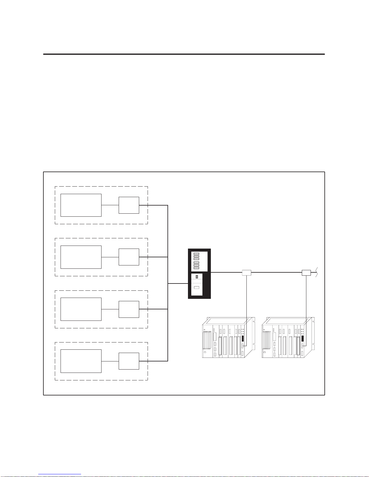
1.1 Introduction
The Gateway
Interface
Distributed Contr
Systems
Foxboro
SPECTRUM
ol
The
TIWAY I Gateway allows a TIWAY I network of PLCs to be hosted by a
Modbus-compatible host system. Figure 1-1 shows the relationship of the
Gateway to one of several possible Modbus-compatible host systems.
The Foxboro SPECTRUM, Fisher PROVOX, and Honeywell TDC 2000 are
distributed control systems which have interfaces to PLCs. These systems
primarily perform supervisory control and data acquisition functions to the
PLCs, using an RS-232-C type of connection into PLC data highways.
For example, the Honeywell TDC 2000 system communicates with the
Gateway by way of a Data Highway Port (DHP), the Fisher PROVOX
system uses a Programmable Controller Interface Unit (PCIU), and the
Foxboro SPECTRUM system uses a FOXNET Device Interface (FDG).
FDG
or
Fisher
PROVOX
or
Honeywell
TDC
2000
or
MODBUS
Compatible
Host System
Figure 1-1 TIWAY
PCIU
DHP
“xyz”
I Gateway as Inter
TIWA
Y I Gateway
TIWA
Y I Network
Programmable Controllers
face Between PLC Network and Host System
I000000
1-2
Product Overview
TIWAY I Gateway User Manual
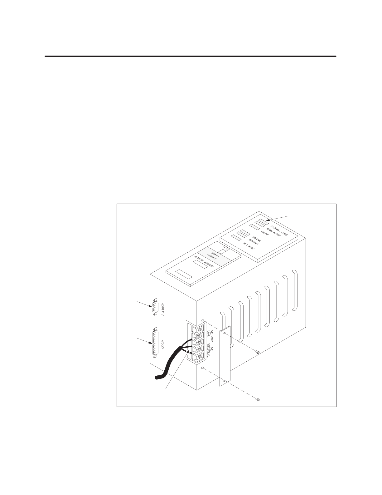
1.2 Basic Operating Features
Inter
face Ports
Two
interface ports are located on the bottom of the TIWAY I Gateway unit.
The AC power connections are also located on the bottom, covered by a
protective plate. (See Figure 1-2.)
•
Host: an RS-232-C host interface port (25-pin female D-shell connector)
• TIWA
Y I: the network port (9-pin female D-shell connector)
The host system is connected by cable to the host interface on the Gateway
The communications cable is supplied with the Gateway
. The TIWAY I port
provides communication interface with the TIWAY I network of PLCs or
other secondary devices.
Refer to Chapter 2 for information on TIWAY I network installation.
Chapter 3 describes the procedures for installing and configuring the
TIWA
Y I Gateway and the communications cables.
Status indicators
TIWAY
I
port
.
Host
port
TIWAY I Gateway User Manual
AC Power
Connections
Figure 1-2 TIWAY
I Gateway
Product Overview
I00xxxx
1-3

Basic Operating Features (continued)
Translating
Commands
between Host and
PLC Network
Data T
ransmission
Rates Supported
The
Gateway provides protocol and electrical interface conversion. A
command issued by the host system is transmitted to the Gateway
. Once it
receives the command, the Gateway converts the protocol and electrical
signals and then relays the command to the PLC which was addressed.
After the PLC responds, the Gateway re-translates the information and
sends it back to the host system through the interface device.
The primary function of the Gateway
, then, is to translate host commands
into TIWAY I commands. These commands are described in Appendix C.
The TIWAY I Gateway supports data transmission rates from 1
second (bps) to 19.2 kbps with the host, and from 1
the network interface. T
able 1-1 summarizes the baud rates supported by
10 bps to 1
10 bits per
15.2 kbps on
the Foxboro, Honeywell, and Fisher host systems.
T
able 1-1
Host System Data Transmission Rates Supported
110 150 300 600 1200 2400 4800 9600 19.2k
Foxboro
Honeywell
Fisher
Data T
ransmission Rates Supported
T
ypes of Data
Accessed
The
Gateway allows access to discrete I/O points and Control Relays
(X, Y
, and C), holding registers (V
-memory), word input and output registers
(WX and WY), as well as performance statistics for each PLC network
interface. Information can be stored in variable (V) memory locations,
retrieved, and changed from the operator’s console of the distributed control
system. Appendix A provides information on the maximum numbers of
discrete inputs and outputs, holding registers, and word input registers.
Examples of data retrieval include the following:
•
If you want to retrieve a process control loop integer value from a PLC,
move this value into a register
, or V
-memory location, corresponding to
the one configured in the distributed control system (refer to the
appropriate DCS manuals).
•
If you want to look at the current value of a counter
into V
-memory (using the ladder logic program) to a location configured
, move this value
as a register in the host system.
Discrete inputs and outputs (Xs, Ys, and Cs) generally do not require special
conditioning in order to be read from the operator
’
s console (as in the Fisher
PROVOX system). See Appendix D for examples.
1-4
Product Overview
TIWAY I Gateway User Manual

Chapter 2
2.1 TIWAY
2.2 Network
I Network and Gateway Installation Checklist
Quick
Refer
Basic
Installation Pr
Requirements
Overview 2-4
Local
Line Cable Characteristics
TIWAY
I Network Characteristics
Local
Line Har
Tap
Housing
Terminating
Twisted-Pair
Important
Local
Line T
Basic
Considerations
Primary
Double
Short
Dr
Multidrop Taps 2-9.
Cable
Obstructions 2-11
Noise Avoidance 2-11.
Routing
Network
. . . . . . . . . . . . . . . . . . . . . . . . . . . . .
ence Installation Steps
ocedures 2-3.
for Installing the Gateway
Media Installation — Local Line
. . . . . . . . . . . . . . . . . . . . . . . . . . . . . . . . . . . . . . . . . . . . . . . . . . . . . . . . . . . . . . . . . . . . . . .
dwar
e Components
. . . . . . . . . . . . . . . . . . . . . . . . . . . . . . . . . . . . . . . . . . . . . . . . . . . . . . . . . . . . . . . . . . .
the Main Line Cable
Cabling
Planning Considerations
ap Spacing Rules
Rule
Dr
. . . . . . . . . . . . . . . . . . . . . . . . . . . . . . . . . . . . . . . . . . . . . . . . . . . . . . . . . . . . . . . . . . .
ops 2-9.
. . . . . . . . . . . . . . . . . . . . . . . . . . . . . . . . . . . . . . . . . . . . . . . . . . . . . . . . . . . . . . . . . .
ops 2-9.
. . . . . . . . . . . . . . . . . . . . . . . . . . . . . . . . . . . . . . . . . . . . . . . . . . . . . . . . . . . . . . . . . . . .
. . . . . . . . . . . . . . . . . . . . . . . . . . . . . . . . . . . . . . . . . . . . . . . . . . . . . . . . . . . . . . . . . . . .
. . . . . . . . . . . . . . . . . . . . . . . . . . . . . . . . . . . . . . . . . . . . . . . . . . . . . . . . . . .
. . . . . . . . . . . . . . . . . . . . . . . . . . . . . . . . . . . . . . . . . . . . . . . . . . . . . . . . . . .
. . . . . . . . . . . . . . . . . . . . . . . . . . . . . . . . . . . . . . . . . . . . . . . . . . . . . . . . . . . . . . . . .
. . . . . . . . . . . . . . . . . . . . . . . . . . . . . . . . . . . . . . . . . . . . . . . . . . . . . . . . . . . . . . . . .
. . . . . . . . . . . . . . . . . . . . . . . . . . . . . . . . . . . . . . . . . . . . . . . . . . . . . . . . . . . . . .
. . . . . . . . . . . . . . . . . . . . . . . . . . . . . . . . . . . . . . . . . . . . . .
. . . . . . . . . . . . . . . . . . . . . . . . . . . . . . . . . . . . . . . . . . . . . . . . . . . .
. . . . . . . . . . . . . . . . . . . . . . . . . . . . . . . . . . . . . . . .
. . . . . . . . . . . . . . . . . . . . . . . . . . . . . . . . . . . . . . . .
. . . . . . . . . . . . . . . . . . . . . . . . . . . . . . . . . . . . . . . . . . . . . . . .
. . . . . . . . . . . . . . . . . . . . . . . . . . . . . . . . . . . . . . . . . . . . . . . . .
. . . . . . . . . . . . . . . . . . . . . . . . . . . . . . . . . . . . . . . . . . . . . .
. . . . . . . . . . . . . . . . . . . . . . . . . . . . . . . . . . . . . . . . . . . . . . .
. . . . . . . . . . . . . . . . . . . . . . . . . . . . . . . . . . . . . . . . . . . . .
. . . . . . . . . . . . . . . . . . . . . . . . . . . . . . . . . . . . . . . . . . . . . . . . . . .
Installation
2-2.
2-2.
2-3.
2-4.
2-4.
2-5.
2-6.
2-6.
2-7.
2-7.
2-7.
2-8.
2-8.
2-8.
2-10.
2.3 Network
Data T
RS-232
TIWAY I Gateway User Manual
Media Installation — RS-232-C Modem Inter
ransmission Characteristics
Pin Assignments
face 2-12.
. . . . . . . . . . . . . . . . . . . . . . . .
. . . . . . . . . . . . . . . . . . . . . . . . . . . . . . . . . . . . . . . . . . . . . . .
. . . . . . . . . . . . . . . . . . . . . . . . . . . . . . . . . . . . . . . . . . . . . . . . . . . . . . . . .
Network Installation
2-12.
2-12.
2-1

2.1 TIWAY I Network and Gateway Installation Checklist
Quick Refer
ence
Installation Steps
Figure 2-1
TIWA
Y I Gateway
is a quick reference list of steps to be taken when installing the
. Refer to Chapter 3 for specific procedures and cautions.
Attach
AC power cable to the Gateway
Run diagnostic tests.
Connect the network and host interface cables.
Configure the host system.
.
Configure the Gateway dipswitches.
Check Gateway indicators for proper operation.
Configure the variable memory of PLCs on the TIWAY I network.
Figure 2-1 Basic
Installation and Set-up Steps
2-2
Network Installation
TIWAY I Gateway User Manual

Basic Installation
Procedures
Some
basic procedures to follow when installing a Gateway system include
the following.
•
Be sure you have all components necessary to install the Gateway and
the network cables. (Refer to the checklist below for required parts.)
•
Install the TIWAY I network and host system interface cables (see
Section 2.2). Also refer to the appropriate host system installation
manuals for specific information on cabling between the host and the
Gateway.
•
Install the Gateway in a NEMA panel or other suitable enclosure (see
Chapter 3 for more details).
Requir
ements for
Installing the
Gateway
The items below are required to install the TIWAY I Gateway and to connect
it to a host system and the TIWAY I network.
TIWA
Y I Gateway
L-shaped mounting brackets and bracket screws, or optional rack
mount kit.
Host interface cable (included; PPX:2462553–0003)
Mounting screws (customer
AC power cable (customer
Loopback connector(s) for user
-supplied)
-supplied)
-initiated diagnostic test (included;
PPX:2703834–0001)
TIWA
Y I T
ap Housing (for Local Line installation) (PPX:500–5606)
T
ap cable for use with Local Line (customer
-supplied), or
RS-232-C/423 cable for use with modems (both cables and modems are
customer-supplied)
TIWAY I Gateway User Manual
Network Installation
2-3

2.2 Network Media Installation — Local Line
Overview
Line Cable
Local
Characteristics
TIWAY
I is a multi-drop communications network. It consists of a main
trunk cable (the “spine”) and dropline cables. The network can connect up to
248 secondaries to a host computer
NOTE:
Although addresses can range from 1 to 254 on TIWAY I, addresses
.
248 through 254 cannot be used because of the limitations of the Modbus
protocol.
The selection of the media interface depends primarily upon two criteria:
the distance to be spanned and the cost of installation. The main trunk can
be up to 25,000 feet long, and each dropline can be up to 100 feet long, with
Local Line. For distances exceeding 25,000 feet, the use of RS-232-C media
interfaces and modems is required.
If cable redundancy is required (two TIWAY I cables), you will need two
Gateways, two cables, and two host system interface devices. Refer to the
appropriate host system user manuals for more specific information on
redundant connections.
The TIWAY I Local Line is a physical signalling technique (baseband,
differential current drive) which operates over shielded, twisted-pair
cabling. The Local Line cable may be up to 25,000 feet long. The Local Line
uses tap housings to simplify the addition of connections onto TIWAY I.
The Local Line is designed to operate with shielded twisted-pair cable which
has a characteristic impedance of 124 ohms. The interface is a male, 9-pin
D-type connector with pin assignments as shown in T
T
able 2-1
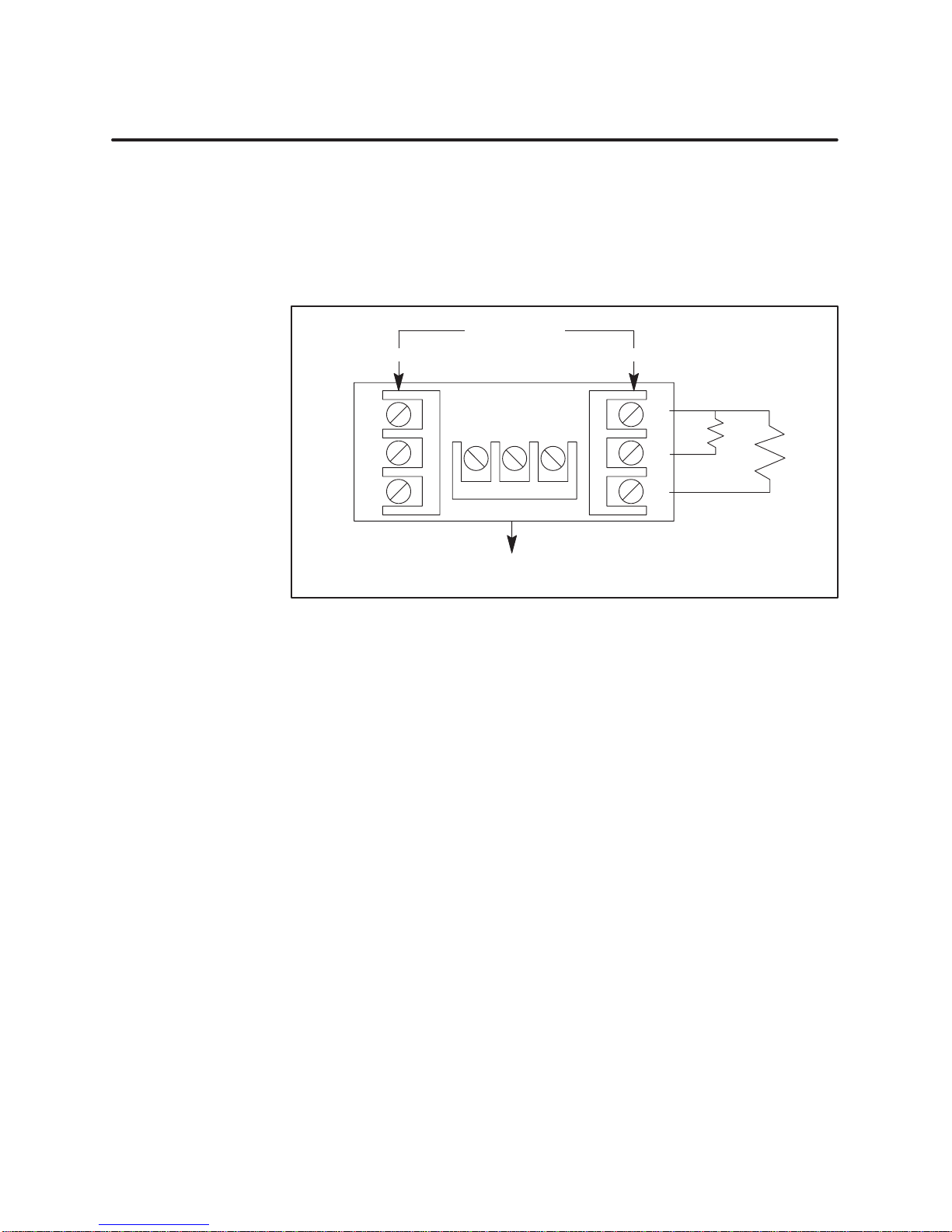
Pin Name Description
1
2
3
4
5
6
7
8
9
Shield
LLM+
LLM–
Pin Assignments for Local Line Connector
Reserved
Reserved
Cable shield and signal common
Reserved
Reserved
Positive biased signal line
Reserved
Reserved
Negative biased signal line
able 2-1.
2-4
Network Installation
TIWAY I Gateway User Manual
TIWA
Y I Network
Characteristics
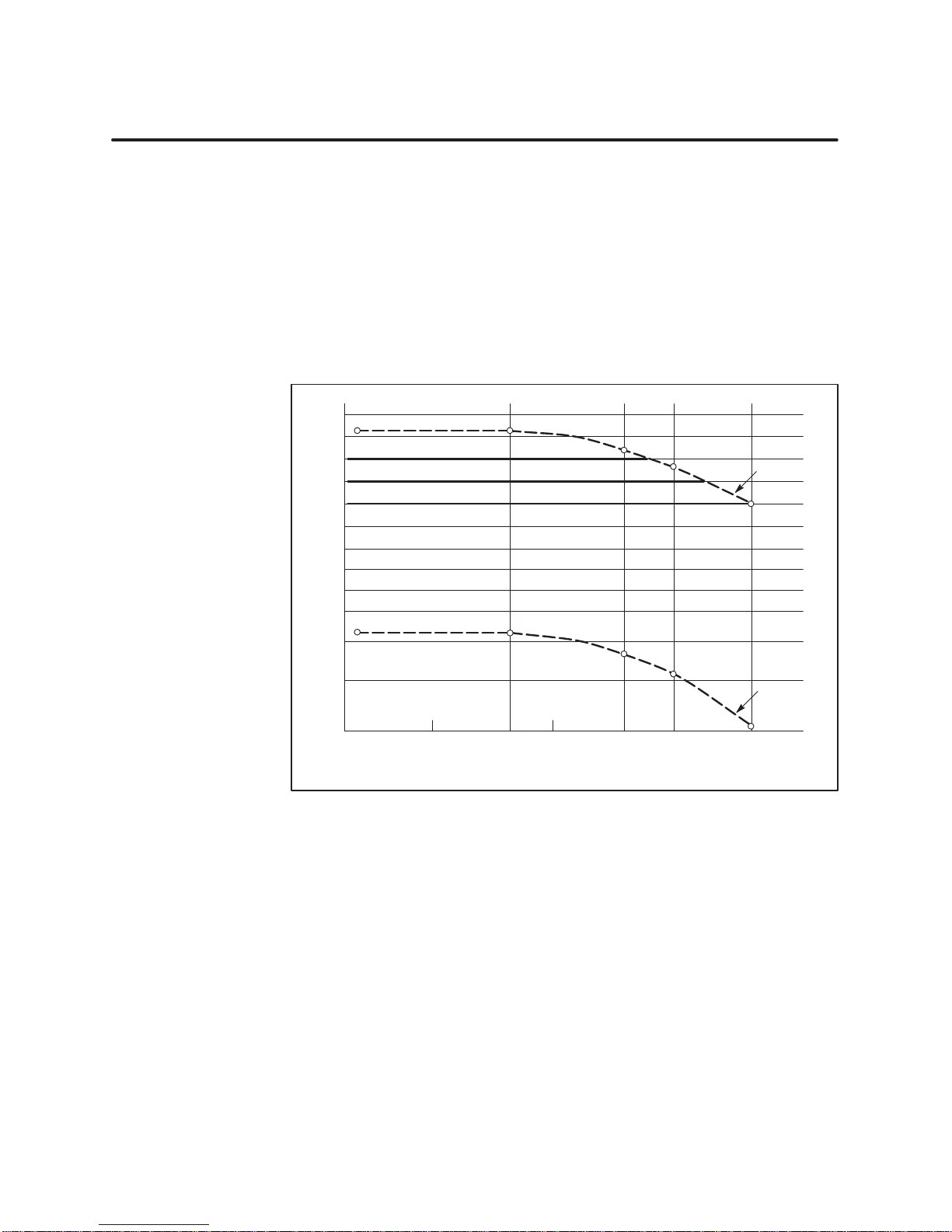
The
TIWAY I network cable consists of a main cable or spine with droplines
or taps for each secondary
. The maximum main line cable length, cable type,
tap length, tap spacing, number of secondaries, and maximum baud rates
are interrelated network variables and have a direct influence upon
network performance.
Figure 2-2 shows the relationship of cable distance to the number of
secondaries for different baud rates for two types of twisted-pair cable. The
cable distance (in thousands of feet) is shown vertically; the maximum
number of units that may be attached is shown horizontally
.
30
25
20
15
10
8
7
6
5
4
3
Cable Distance (1000’s of feet)
2
1
19.2
kbps
38.4 kbps
57.6 kbps
1
15.2 kbps
1
15.2 kbps or lower
Cable
Figure 2-2 Number
Belden 9860
Belden 9271
10 50 100 250
205
Unit Loading (Number of Stations)
of Local Line Secondaries vs. Cable Distance
I000000
As shown in Figure 2-2, when you use Belden 9860 cable (or its equivalent),
up to 75 stations can be attached to a network operating at 38.4 kbps and
having a spine length of 20,000 feet. At 1
a Local Line network having 248 stations is 10,000 feet.
TIWAY I Gateway User Manual
15.2 kbps, the maximum length of
Network Installation
2-5
Network Media Installation — Local Line (continued)
Local Line
Hardware
Components
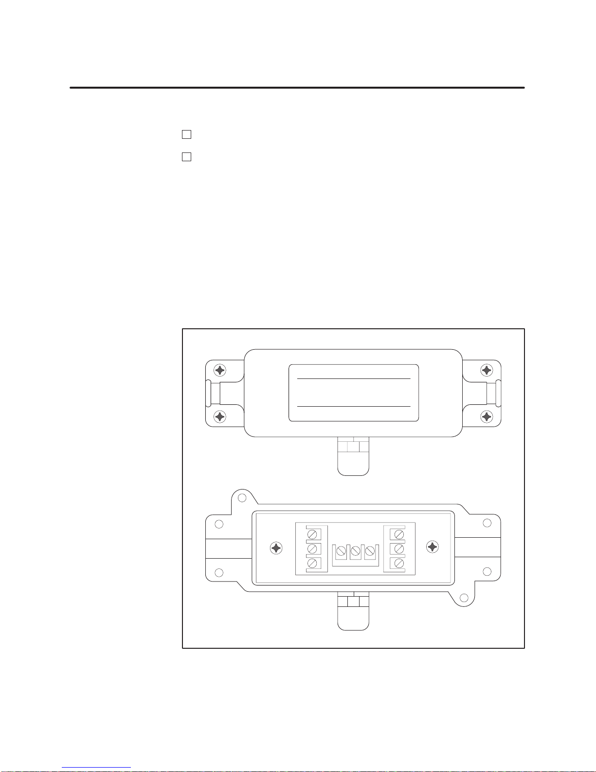
T
ap Housing
The
hardware components of a Local Line network consist of the following:
TIWA
Y I T
ap Housing (PPX:500–5606)
Shielded, twisted-pair cabling (customer
-supplied)
These components are described in the following sections.
The TIWAY I T
ap Housing, shown in Figure 2-3, is designed specifically for
Local Line networks. The tap housing can be mounted rigidly to a NEMA
panel or other enclosure. It could also be used to splice cables in a cable tray
without being rigidly mounted.
The tap housing contains terminating resistors, and it also provides noise
isolation for attached cabling, resists moisture, and relieves strain, thus
allowing an orderly connection to the TIWAY I network. One tap housing is
provided with each Gateway Local Line connection.
Siemens
NETWORK TAP HOUSING
MODEL 500–5606 ASSY 2702766–0001
Siemens Industrial Automation, Inc.
2-6
Network Installation
G
W
B
T
op cover removed to show
cable connections.
Figure 2-3 TIWAY
GWB
I T
ap Housing
G
W
B
I000000
TIWAY I Gateway User Manual
Ter
minating the
Main Line Cable
The
terminating resistors must be used to ensure that the main line cable is
properly terminated and biased for improved reliability
. Each tap housing is
supplied with terminating resistors to connect to the ends of the main line
cable. At each end, a terminating resistor must be connected between LLM+
and the cable shield and also between LLM– and the cable shield inside the
tap housing.
Network Cable
Input Output
Twisted-Pair
Cabling
Important Planning
Considerations
W
G
B
Cable
to Module
Figure 2-4 Terminating
GWB
the Local Line
W
G
B
Termination
Resistors:
68
ohms
5%
1/4 watt
Siemens Industrial Automation recommends Belden 9860 twisted-pair
cabling or its equivalent for use as the Local Line network spine. Belden
9271 or its equivalent should be used for the dropline. Brands other than
those listed here will be specified by Siemens upon request.
Some major points to consider during the planning phase of a Local Line
network are the following.
•
From the start, allow for system growth. Make provisions for the
attachment of additional computing devices by routing cables through
all probable areas of future plant expansion.
I000000
•
•
•
TIWAY I Gateway User Manual
Always make the network flexible enough to allow for re-arrangement
of plant equipment.
Since network system noise is usually picked up by its interconnecting
wiring, take steps during installation to bypass or eliminate noise
sources.
If cable redundancy is required, make sure the two cables are never
routed along the same path, since the environmental and other factors
which disable one cable will very likely disable the second cable.
Network Installation
2-7
Network Media Installation — Local Line (continued)
Local Line T
ap
Spacing Rules
Local
Line networks must adhere to specific tap spacing requirements to
maintain signal integrity
. These requirements are outlined in the following
sections.
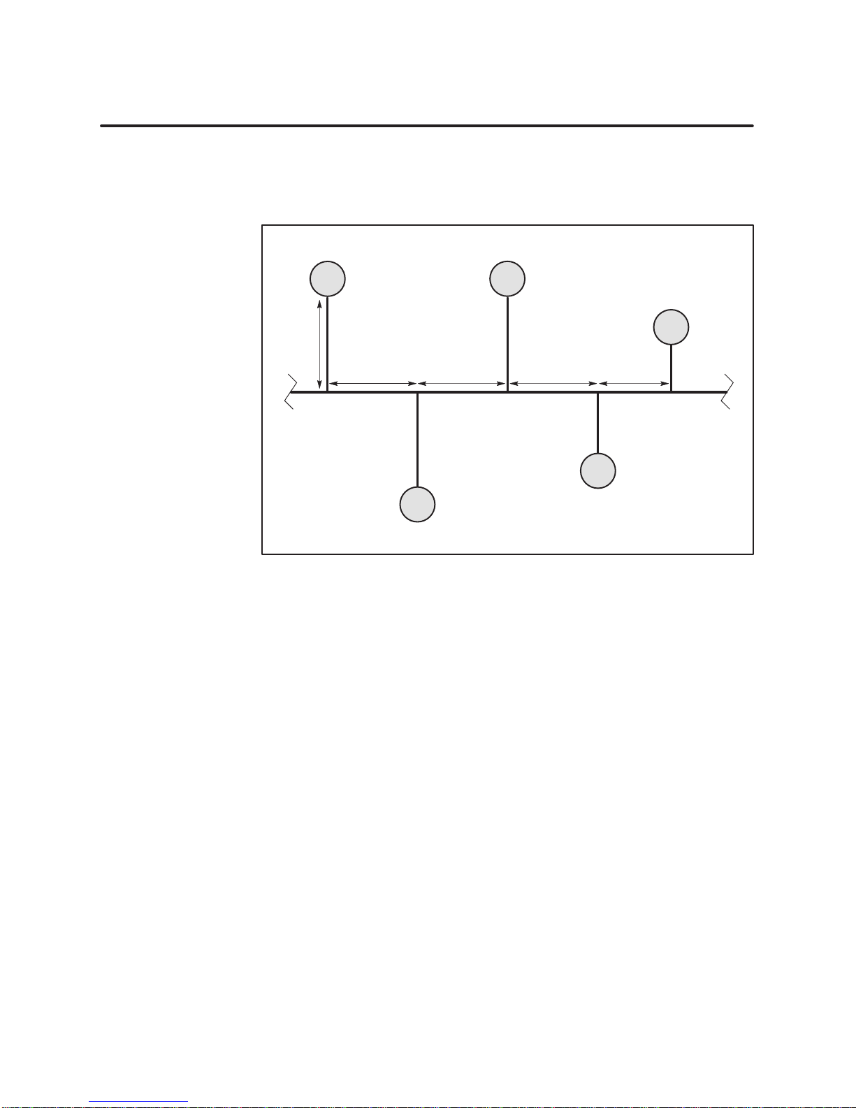
100′ 100′
50′ min 50′min 50′ 30′
60′
100′
20′
Basic
Considerations
Primary Rule
I000000
Figure 2-5 Basic Tap Spacing Rules
The rules for determining the correct distances between taps exist simply
for the prevention of signal degradation caused by reflections.
Prior to configuring the distances between taps in the network cable, select
a single tap as a physical point to use as reference. This tap should be one of
the taps on the end of the network.
The primary rule is that the minimum distance from one tap to the next
cannot
(drop
be less than one half the distance of the previous tap cable
line) length. This rule should be applied starting at the first tap on the
network all the way to the end. Then, from the last tap on the network, the
same rule should be applied back to the first tap again.
2-8
Network Installation
TIWAY I Gateway User Manual
Double Drop
80′
Drop
lines less
than 36 inches
can be ignored.
36″max
100′
max
Double Dr
ops
30′
100′
30″
50′ min
100′
I000000
Figure 2-6 Additional Tap Spacing Rules
If a tap cable is installed
less than the minimum
distance as stated in the
primary rule, then the two drops, the previous one and the one being
installed, are considered a
Double
drops are allowed, but triple drops are not allowed.
double
drop
.
After installing a double drop, the next tap must be placed at the minimum
distance or farther
. In this case, the minimum distance would be one half
the distance of the longest of the two tap lines making up the double drop.
Short Dr
ops
Drops that have a tap line that is
calculating the minimum distance between taps.
Multidr
op T
aps
There is no limit to the number of drop stations that can be connected to the
same tap line.
Each station must have its own tap, and the overall drop line length cannot
exceed 100 feet. The cable used to attach each station to the drop line
cannot
TIWAY I Gateway User Manual
less than 36 inches
exceed the 36-inch maximum.
can be ignored in
Network Installation
2-9

Network Media Installation — Local Line (continued)
Cable Routing
!
CAUTION
Cable
routing should be planned as if the path between all stations on the
network were free of obstructions. The next step is to modify the first
routing to account for obstructions, then calculate the amount of cable
needed.
Observe
all local and national electrical and fire codes when
installing wiring.
In
general, there are three types of network cabling routes:
• Under-floor
• In-ceiling
•
Surface ducting
Any combination of these three routes may be used on a single network. The
choice is often determined by whether or not the building (or buildings) in
which the network is being installed is new construction or an existing
building. The following paragraphs describe some of the advantages and
disadvantages of each type of cable routing.
Under-floor
ducts or
in ducts are usually expensive, and while they are better
— For under
-floor routing, the cable can be enclosed within
, with raised flooring, in the “open air
.” Under
-floor systems enclosed
-protected against
unauthorized taps than are open-air systems, they often make future
expansion of the network more difficult and expensive.
Open-air under
maximum network expansion and flexibility
In-ceiling
-floor cabling systems usually provide good access, and allow
.
— For in-ceiling routing, network cables are usually supported
in troughs or with hooks and clamps every 10 or 15 feet. Some advantages
of in-ceiling installation are the following.
• Flexibility
•
Low-cost installation
•
Accessibility to cabling
2-10
Network Installation
TIWAY I Gateway User Manual

Some
disadvantages are the following.
•
Is is impractical for buildings without drop ceilings
Obstructions
• W
•
Surface
orking in high ceilings can be hazardous
Ceilings often collect dust and other debris
ducting
— Surface ducting for network cabling is usually
installed along the baseboards or is attached to walls at desktop height.
While surface ducting ordinarily protects cables from both physical and EMI
effects, it may also require that network computing devices be positioned
near a wall.
Aside from physical obstructions such as posts, walls, and partitions,
electrical interference should also be avoided. Some sources of interference
are the following.
•
Power distribution mains
•
Arcing motors
•
Fluorescent lighting
• Teletypes
Undesired signal transfer (cross-talk) between adjacent circuits
•
•
Noise A
voidance
In general, network cabling should never come into direct contact with any
electrical conductor
should be grounded in accordance with applicable electrical codes. Keep a
minimum of three feet of distance between all network cabling and the
following sources of noise.
•
•
• Transformers •
• Rectifiers •
TIWAY I Gateway User Manual
Poor cable-to-equipment impedance matching
. If cabling is installed inside a conduit, the conduit
Power lines
Electric motors
• Generators
•
Electric welders
Induction furnaces and heaters
All sources of microwave radiation
Network Installation
2-11

2.3 Network Media Installation — RS-232-C Modem Interface
Data Transmission
Characteristics
RS-232 Pin
Assignments
The
physical layer in TIWAY I provides a modem interface for synchronous
or asynchronous communications at data transmission rates up to 1
15.2 K
bps. The modem interface provides standard signals for control of two-way
alternate data transmission using both half and full duplex modems.
The modem interface is a standard T
ype E DTE configuration as defined in
the EIA RS-232-C standard. This interface uses a male 25-pin D-type
connector plug on the communication cable. The pin assignments are listed
in T
able 2-2.
T
able 2-2 RS-232-C Connector Pin Assignments
Pin No. Description
1 Protective Ground
2 Transmit Data
3 Receive Data
4 Request to Send (RTS)
5 Clear to Send (CTS)
6 Data Set Ready (DSR)
7 Signal Ground
8 Receive Line Signal Detector/Data Carrier Detect (RLSD/DCD)
15 Transmitter Signal Element Timing
17 Receiver Signal Element Timing
20 Data Terminal Ready (DTR)
2-12
Network Installation
TIWAY I Gateway User Manual

Chapter 3
Gateway
3.1 Installing
Basic
Power
3.2 Dipswitch
Overview 3-6
Dipswitch
Dipswitch
3.3 Switches
Online/Offline
Self-Test
Reset
Status
Gateway
Comm
Online 3-11
Receive 3-11
Transmit 3-11
Test
the TIWAY I Gateway
Mounting Guidelines
Connections and Initialization
Configuration and Function
. . . . . . . . . . . . . . . . . . . . . . . . . . . . . . . . . . . . . . . . . . . . . . . . . . . . . . . . . . . . . . . . . . . . . . .
Settings for the Host Inter
Settings for the Network Interface Port
and Indicator Lights
Button
Button
Indicator Lights
Good
Active
. . . . . . . . . . . . . . . . . . . . . . . . . . . . . . . . . . . . . . . . . . . . . . . . . . . . . . . . . . . . . . . . . . . . . . . . . .
. . . . . . . . . . . . . . . . . . . . . . . . . . . . . . . . . . . . . . . . . . . . . . . . . . . . . . . . . . . . . . . . . . . . . . . .
. . . . . . . . . . . . . . . . . . . . . . . . . . . . . . . . . . . . . . . . . . . . . . . . . . . . . . . . . . . . . . . . . . . . . . . .
Mode
. . . . . . . . . . . . . . . . . . . . . . . . . . . . . . . . . . . . . . . . . . . . . . . . . . . . . . . . . . . . . . . . . . . . .
Installation and Configuration
. . . . . . . . . . . . . . . . . . . . . . . . . . . . . . . . . . . . . . . . . . . . . . . . . .
. . . . . . . . . . . . . . . . . . . . . . . . . . . . . . . . . . . . . . . . . . . . . . . . . . . . .
. . . . . . . . . . . . . . . . . . . . . . . . . . . . . . . . . . . . . . . . . . . .
. . . . . . . . . . . . . . . . . . . . . . . . . . . . . . . . . . . . . . . . . . .
face Port
. . . . . . . . . . . . . . . . . . . . . . . . . . . . . . . . . . . . . . . . . . . . . . . . . . .
Switch
. . . . . . . . . . . . . . . . . . . . . . . . . . . . . . . . . . . . . . . . . . . . . . . . . . . . . . . . . . . . . . . . . . .
. . . . . . . . . . . . . . . . . . . . . . . . . . . . . . . . . . . . . . . . . . . . . . . . . . . . . . . . . . .
. . . . . . . . . . . . . . . . . . . . . . . . . . . . . . . . . . . . . . . . . . . . . . . . . . . . . . . . . . . . . . . .
. . . . . . . . . . . . . . . . . . . . . . . . . . . . . . . . . . . . . . . . . . . . . . . . . . . . . . . . . .
. . . . . . . . . . . . . . . . . . . . . . . . . . . . . . . . . . . . . . . . . . . . . . . . . . . . . . . . . . . . . . .
. . . . . . . . . . . . . . . . . . . . . . . . . . . . . . . . . . . . . . . . . . . . . . . . . . . . . . . . . . . . . . . . .
. . . . . . . . . . . . . . . . . . . . . . . . . . . . . . . . . . . .
. . . . . . . . . . . . . . . . . . . . . . . . . . . . . . . .
3-2.
3-2.
3-3.
3-6.
3-7.
3-8.
3-10.
3-10.
3-10.
3-10.
3-11.
3-11.
3-11.
3-11.
3.4 Diagnostic Tests 3-12.
Built-In
Power-On Test 3-12.
Operational
User-Initiated Test 3-13.
Burn-In
Diagnostic T
Diagnostic T
and Final T
. . . . . . . . . . . . . . . . . . . . . . . . . . . . . . . . . . . . . . . . . . . . . . . . . . . . . . . . . . . . . . . .
ests 3-12.
. . . . . . . . . . . . . . . . . . . . . . . . . . . . . . . . . . . . . . . . . . . . . . . . . . . . . . . . .
. . . . . . . . . . . . . . . . . . . . . . . . . . . . . . . . . . . . . . . . . . . . . . . . . . . . . . . . . . . . . . . . .
est 3-12.
. . . . . . . . . . . . . . . . . . . . . . . . . . . . . . . . . . . . . . . . . . . . . . . . . . . .
. . . . . . . . . . . . . . . . . . . . . . . . . . . . . . . . . . . . . . . . . . . . . . . . . . . . . . . . . . . . . .
ests 3-14.
. . . . . . . . . . . . . . . . . . . . . . . . . . . . . . . . . . . . . . . . . . . . . . . . . . . . . . . . . .
TIWAY I Gateway User Manual
Gateway Installation and Configuration
3-1
 Loading...