

Siemens SIMATIC TeleControl DNP3 Configuration Manual

___________________
___________________
___________________
___________________
___________________
___________________
___________________
___________________
___________________
SIMATIC NET
TeleControl
Configuration - DNP3
Configuration Manual
Configuration and diagnostics
11/2018
C79000
Preface
Functions and requirements
1
Communication mechanisms
2
Configuration
3
Diagnostics
4
OUC program blocks (CP)
A
SINEMA Remote Connect
(CP)
B
WBM of the TIM 1531 IRC
C
Bibliography
D
-G8976-C508-01

Siemens AG
Division Process Industries and Drives
Postfach 48 48
90026 NÜRNBERG
GERMANY
C79000-G8976-C508-01
Ⓟ
Copyright © Siemens AG 2018.
All rights reserved
Legal information
Warning notice system
DANGER
indicates that death or severe personal injury will result if proper precautions are not taken.
WARNING
indicates that death or severe personal injury may result if proper precautions are not taken.
CAUTION
indicates that minor personal injury can result if proper precautions are not taken.
NOTICE
indicates that property damage can result if proper precautions are not taken.
Qualified Personnel
personnel qualified
Proper use of Siemens products
WARNING
Siemens products may only be used for the applications described in the catalog and in the relevant technical
ambient conditions must be complied with. The information in the relevant documentation must be observed.
Trademarks
Disclaimer of Liability
This manual contains notices you have to observe in order to ensure your personal safety, as well as to prevent
damage to property. The notices referring to your personal safety are highlighted in the manual by a safety alert
symbol, notices referring only to property damage have no safety alert symbol. These notices shown below are
graded according to the degree of danger.
If more than one degree of danger is present, the warning notice representing the highest degree of danger will
be used. A notice warning of injury to persons with a safety alert symbol may also include a warning relating to
property damage.
The product/system described in this documentation may be operated only by
task in accordance with the relevant documentation, in particular its warning notices and safety instructions.
Qualified personnel are those who, based on their training and experience, are capable of identifying risks and
avoiding potential hazards when working with these products/systems.
Note the following:
documentation. If products and components from other manufacturers are used, these must be recommended
or approved by Siemens. Proper transport, storage, installation, assembly, commissioning, operation and
maintenance are required to ensure that the products operate safely and without any problems. The permissible
All names identified by ® are registered trademarks of Siemens AG. The remaining trademarks in this publication
may be trademarks whose use by third parties for their own purposes could violate the rights of the owner.
We have reviewed the contents of this publication to ensure consistency with the hardware and software
described. Since variance cannot be precluded entirely, we cannot guarantee full consistency. However, the
information in this publication is reviewed regularly and any necessary corrections are included in subsequent
editions.
for the specific
11/2018 Subject to change

Preface
Validity of this manual
Supported modules
Structure of the documentation
Manual / Operating instructions
SINAUT ST7 system manual
Volume 1 - System and hardware
Volume 2 - Configuration under STEP 7 V5
Volume 3 - Configuration under STEP 7 Professional (TIA Portal)
This manual is valid for all communications modules of the SIMATIC NET range listed below
which support the telecontrol protocol DNP3.
Note the structure of the documentation.
You can find the devices for which the configuration manual is valid in the section
Communications modules (Page 11).
The documentation for the SIMATIC NET communications modules for Telecontrol consists
of the following manuals in each case:
● Manual or operating instructions
● One or more configuration manuals
The documentation for the modules specified above consists of the following manuals and
contents:
●
Valid for the respective module or module group
– Application and functions
– Requirements (CPUs, configuration software, etc.)
– Hardware description
– Installation, wiring, commissioning, operation
– Diagnostics, maintenance
– Technical specifications, approvals, accessories
●
–
Valid for: TIM 3V-IE, TIM 3V-IE Advanced, TIM 4R-IE
Hardware description, installation, wiring, commissioning, operation, technical
specifications, approvals
Configuration - DNP3
Configuration Manual, 11/2018, C79000-G8976-C508-01
–
Valid for: TIM 3V-IE, TIM 3V-IE Advanced, TIM 4R-IE
–
Valid for all ST7-capable communications modules
3

Preface
Configuration manual DNP3
Configuration manual IEC
Abbreviations/device names
Module / device
WBM
New in this release
Current manual release on the Internet
Required experience
Cross references
●
Configuration and diagnostics in STEP 7 Professional (TIA Portal)
Valid for all SIMATIC NET communications modules that support the DNP3 protocol.
●
Configuration and diagnostics in STEP 7 Professional (TIA Portal)
Valid for all SIMATIC NET communications modules that support the protocol IEC
60870-5-101/104.
You can find the Internet links for the manuals in the Bibliography (Page 187).
This manual often uses the following abbreviations/acronyms:
●
Names for the respective communications modules
●
"WBM" is the acronym for the "Web Based Management", the pages of the TIM Web
server for configuration and diagnostics data.
First issue
You will also find the current version of this manual on the Internet pages of Siemens
Industry Online Support:
Link: (https://support.industry.siemens.com/cs/ww/en/ps/21764/man)
Knowledge in the following areas is required for configuration and diagnostics of the devices:
● Setting up industrial networks with security functions
● Data transfer via WAN networks
● SIMATIC STEP 7 Professional
In this manual there are often cross references to other sections.
To be able to return to the initial page after jumping to a cross reference, some PDF readers
support the command <Alt>+<left arrow>.
Configuration - DNP3
4 Configuration Manual, 11/2018, C79000-G8976-C508-01

Preface
License conditions
Note
Open source software
The product contains open source software. Read the license conditions for open source
software carefully before using the product.
Security information
SIMATIC NET glossary
The manual for the relevant product provides information on finding the license conditions.
Siemens provides products and solutions with industrial security functions that support the
secure operation of plants, systems, machines and networks.
In order to protect plants, systems, machines and networks against cyber threats, it is
necessary to implement – and continuously maintain – a holistic, state-of-the-art industrial
security concept. Siemens’ products and solutions constitute one element of such a concept.
Customers are responsible for preventing unauthorized access to their plants, systems,
machines and networks. Such systems, machines and components should only be
connected to an enterprise network or the internet if and to the extent such a connection is
necessary and only when appropriate security measures (e.g. firewalls and/or network
segmentation) are in place.
For additional information on industrial security measures that may be implemented, please
visit
Link: (http://www.siemens.com/industrialsecurity)
Siemens’ products and solutions undergo continuous development to make them more
secure. Siemens strongly recommends that product updates are applied as soon as they are
available and that the latest product versions are used. Use of product versions that are no
longer supported, and failure to apply the latest updates may increase customers’ exposure
to cyber threats.
To stay informed about product updates, subscribe to the Siemens Industrial Security RSS
Feed under
Link: (http://www.siemens.com/industrialsecurity)
Explanations of many of the specialist terms used in this documentation can be found in the
SIMATIC NET glossary.
You will find the SIMATIC NET glossary here:
● SIMATIC NET Manual Collection or product DVD
The DVD ships with certain SIMATIC NET products.
● On the Internet under the following address:
Link: (http://support.automation.siemens.com/WW/view/en/50305045)
Configuration - DNP3
Configuration Manual, 11/2018, C79000-G8976-C508-01
5

Preface
Configuration - DNP3
6 Configuration Manual, 11/2018, C79000-G8976-C508-01

Table of contents
Preface ................................................................................................................................................... 3
1 Functions and requirements .................................................................................................................. 11
2 Communication mechanisms ................................................................................................................ 25
3 Configuration ........................................................................................................................................ 29
1.1 Communications modules ...................................................................................................... 11
1.2 Configuration examples .......................................................................................................... 12
1.3 Usable CPUs .......................................................................................................................... 15
1.4 Software requirements ............................................................................................................ 15
1.5 Performance data and configuration limits ............................................................................. 16
1.5.1 TIM 1531 IRC .......................................................................................................................... 16
1.5.2 TIM 4R-IE DNP3 / TIM 3V-IE DNP3 ....................................................................................... 17
1.5.3 CP 1243-8 IRC ........................................................................................................................ 19
1.5.4 CP 1243-1 ............................................................................................................................... 21
1.5.5 CP 1542SP-1 IRC ................................................................................................................... 22
1.6 PG routing ............................................................................................................................... 23
2.1 Addressing and network configuration .................................................................................... 25
2.2 Communications options ........................................................................................................ 26
2.3 Connection establishment ...................................................................................................... 27
2.4 Acknowledgment ..................................................................................................................... 28
3.1 Security recommendations ..................................................................................................... 29
3.2 Communication types ............................................................................................................. 32
3.3 Basic settings / Options .......................................................................................................... 33
3.3.1 Basic settings .......................................................................................................................... 33
3.3.2 Options .................................................................................................................................... 35
3.4 Configuration of interfaces, networks and network nodes ...................................................... 36
3.4.1 WAN settings of the interfaces ............................................................................................... 36
3.4.2 Networking of the interfaces ................................................................................................... 38
3.5 Ethernet interface .................................................................................................................... 40
3.5.1 Ethernet interface > address parameters ............................................................................... 40
3.5.2 Advanced options ................................................................................................................... 41
3.5.2.1 TCP connection monitoring .................................................................................................... 41
3.5.2.2 Transmission settings ............................................................................................................. 42
3.5.3 Web server access ................................................................................................................. 42
3.5.3.1 CP ........................................................................................................................................... 42
3.5.3.2 TIM 1531 IRC .......................................................................................................................... 42
3.6 Serial interface ........................................................................................................................ 43
3.6.1 Advanced options ................................................................................................................... 43
Configuration - DNP3
Configuration Manual, 11/2018, C79000-G8976-C508-01
7

Table of contents
3.6.1.1 Dedicated line ........................................................................................................................ 43
3.6.1.2 Dialup network ....................................................................................................................... 47
3.6.1.3 Transmission settings ............................................................................................................ 51
3.7 Configuring WAN networks .................................................................................................... 51
3.8 DNP3 parameters of the interfaces........................................................................................ 53
3.8.1 Transmission settings – DNP3 ............................................................................................... 53
3.8.2 Settings DNP3 master ........................................................................................................... 55
3.8.3 Settings DNP3 station ............................................................................................................ 56
3.9 Web server ............................................................................................................................. 59
3.10 Web diagnostics ..................................................................................................................... 61
3.10.1 Web diagnostics of the TIM 1531 IRC ................................................................................... 61
3.11 DNS configuration .................................................................................................................. 61
3.12 Communication with the CPU ................................................................................................ 62
3.13 Time-of-day synchronization .................................................................................................. 67
3.14 E-mail configuration ............................................................................................................... 72
3.15 Subscriber numbers ............................................................................................................... 73
3.16 SNMP ..................................................................................................................................... 74
3.17 Security (CP) and certificates ................................................................................................ 75
3.17.1 Parameters ............................................................................................................................. 75
3.17.2 Security user .......................................................................................................................... 75
3.17.3 Log settings - Filtering of the system events ......................................................................... 76
3.17.4 VPN ........................................................................................................................................ 76
3.17.4.1 VPN (Virtual Private Network) ................................................................................................ 76
3.17.4.2 Creating a VPN tunnel for S7 communication between stations ........................................... 77
3.17.4.3 VPN communication with SOFTNET Security Client (engineering station) ........................... 79
3.17.4.4 Establishment of VPN tunnel communication between the CP and SCALANCE M ............. 80
3.17.4.5 CP as passive subscriber of VPN connections ...................................................................... 80
3.17.5 Certificate manager ................................................................................................................ 81
3.17.6 Handling certificates ............................................................................................................... 81
3.18 Protection (TIM 1531 IRC) ..................................................................................................... 83
3.18.1 Protection ............................................................................................................................... 83
3.18.2 Configuring access protection ................................................................................................ 85
3.19 Telecontrol connections ......................................................................................................... 86
3.19.1 Telecontrol connections ......................................................................................................... 86
3.19.2 "Network data" editor ............................................................................................................. 87
3.19.3 Specifying connection paths .................................................................................................. 89
3.19.4 Connection table .................................................................................................................... 92
3.19.5 Parameters of the DNP3 connections ................................................................................... 97
3.19.5.1 General .................................................................................................................................. 97
3.19.5.2 TCP connection monitoring .................................................................................................... 98
3.19.5.3 DNP3 security options ........................................................................................................... 99
3.19.5.4 Transmission settings – DNP3 ............................................................................................. 102
3.19.5.5 Third-party device parameters ............................................................................................. 102
3.20 Configuring data points ........................................................................................................ 103
3.20.1 Data point configuration ....................................................................................................... 103
Configuration - DNP3
8 Configuration Manual, 11/2018, C79000-G8976-C508-01

Table of contents
4 Diagnostics ......................................................................................................................................... 133
A OUC program blocks (CP) .................................................................................................................. 157
3.20.2 Datapoint types ..................................................................................................................... 109
3.20.3 "General" tab ......................................................................................................................... 112
3.20.4 Rules for configuring the data point index: ........................................................................... 113
3.20.5 Process image, type of transmission, event classes ............................................................ 113
3.20.6 Read cycle ............................................................................................................................ 115
3.20.7 "Trigger“ tab .......................................................................................................................... 116
3.20.8 Threshold value trigger ......................................................................................................... 117
3.20.9 Analog value preprocessing ................................................................................................. 119
3.20.10 Command output .................................................................................................................. 125
3.20.11 Partner stations ..................................................................................................................... 130
3.21 Configuring messages .......................................................................................................... 130
3.21.1 Messages .............................................................................................................................. 130
3.21.2 Character set for messages .................................................................................................. 132
4.1 Diagnostics options ............................................................................................................... 133
4.2 Online security diagnostics via port 8448 (CP) ..................................................................... 135
4.3 Online functions .................................................................................................................... 135
4.4 SNMP .................................................................................................................................... 136
4.5 SINAUT special diagnostics ................................................................................................. 137
4.5.1 SINAUT-Spezial-Diagnose - Gültigkeit ................................................................................. 137
4.5.2 TIM diagnostics ..................................................................................................................... 138
4.5.2.1 TIM Diagnostics - functions .................................................................................................. 138
4.5.2.2 TIM Diagnostics - Memory tab .............................................................................................. 139
4.5.2.3 TIM Diagnostics - Message buffer tab .................................................................................. 139
4.5.2.4 TIM Diagnostics - Communication tab .................................................................................. 141
4.5.2.5 TIM Diagnostics - Time Synchronization tab ........................................................................ 141
4.5.2.6 TIM Diagnostics - Time tab ................................................................................................... 141
4.5.2.7 TIM Diagnostics - Filesystem tab .......................................................................................... 142
4.5.2.8 TIM diagnostics - IP Parameters tab .................................................................................... 142
4.5.2.9 TIM diagnostics - IP statistics tab ......................................................................................... 142
4.5.2.10 TIM diagnostics - MSC Communication tab ......................................................................... 143
4.5.3 TIM subscriber diagnostics ................................................................................................... 145
4.5.3.1 TIM Subscriber Diagnostics - functions ................................................................................ 145
4.5.3.2 TIM Subscriber Diagnostics - Status tab .............................................................................. 147
4.5.3.3 TIM Subscriber Diagnostics - Partner tab ............................................................................. 148
4.5.3.4 TIM Subscriber Diagnostics - Dialing extern tab .................................................................. 149
4.5.3.5 TIM Subscriber Diagnostics - Polling intern .......................................................................... 150
4.5.4 TD7onTIM diagnostics .......................................................................................................... 151
4.5.4.1 TD7onTIM Diagnostics - functions ........................................................................................ 151
4.6 Processing status of the messages (e-mail) ......................................................................... 153
4.7 Maintenance ......................................................................................................................... 155
A.1 Validity .................................................................................................................................. 157
A.2 Program blocks for OUC ....................................................................................................... 157
A.3 Changing the IP address during runtime .............................................................................. 159
Configuration - DNP3
Configuration Manual, 11/2018, C79000-G8976-C508-01
9

Table of contents
B SINEMA Remote Connect (CP) ........................................................................................................... 161
C WBM of the TIM 1531 IRC ................................................................................................................... 167
D Bibliography ......................................................................................................................................... 187
Index ................................................................................................................................................... 191
B.1 Validity .................................................................................................................................. 161
B.2 Connection to SINEMA RC .................................................................................................. 161
B.3 Telecontrol via SINEMA RC ................................................................................................. 163
B.4 Security > VPN > SINEMA Remote Connect ...................................................................... 164
C.1 Supported Web browsers .................................................................................................... 167
C.2 Establishing a connection to the WBM of the TIM ............................................................... 167
C.3 General functions of the WBM ............................................................................................. 168
C.4 Start page ............................................................................................................................. 169
C.5 System ................................................................................................................................. 171
C.5.1 Device info ........................................................................................................................... 171
C.5.2 SD card ................................................................................................................................ 171
C.5.3 System time ......................................................................................................................... 172
C.5.4 NTP ...................................................................................................................................... 172
C.5.5 Web server ........................................................................................................................... 172
C.5.6 DNS configuration ................................................................................................................ 173
C.6 Maintenance ......................................................................................................................... 173
C.6.1 Firmware .............................................................................................................................. 173
C.6.2 Operating status ................................................................................................................... 174
C.7 Diagnostics ........................................................................................................................... 176
C.7.1 Events .................................................................................................................................. 176
C.7.2 Notifications .......................................................................................................................... 177
C.8 LAN ...................................................................................................................................... 178
C.8.1 Ethernet interface [Xn] ......................................................................................................... 178
C.9 Telecontrol ........................................................................................................................... 180
C.9.1 Partner information .............................................................................................................. 180
C.9.1.1 Connection overview ............................................................................................................ 180
C.9.1.2 Send buffer ........................................................................................................................... 183
C.9.2 Data points ........................................................................................................................... 185
C.10 Logging ................................................................................................................................ 186
Configuration - DNP3
10 Configuration Manual, 11/2018, C79000-G8976-C508-01

1
1.1
Communications modules
Communications modules for the telecontrol protocol DNP3
Module
Article number
Number of inter-
faces *
Station type
STEP 7
product
Required
firmware
IE
RS
Master
Node station
Station
6GK7 543-1MX00-0XE0
Professional
6NH7803-4BA00-0AA0
6NH7803-3BA00-0AA0
Professional
- *** - **
Professional
6AG1 243-1BX30-2AX0
- - **
Professional
6GK7 542-6VX00-0XE0
- - -
Professional
*
**
*** The connection of a TS-Module to the CP 1243-8 IRC is not supported for DNP3.
The following SIMATIC NET communications modules can be used for the telecontrol
protocol DNP3.
You will find the TIM 4R-IE DNP3 with article number 6NH7803-4BA00-0AA0 twice in the
STEP 7 catalog, as built-in unit (S7-300 rack) and as stand-alone device.
Meaning of symbols in the table:
● X = Supported
● - = Not supported
Table 1- 1 Communications modules for DNP3
TIM 1531 IRC
TIM 4R-IE DNP3 /
TIM 4R-IE DNP3 Stand-alone
TIM 3V-IE DNP3
CP 1243-8 IRC
6GK7 243-8RX30-0XE0
CP 1243-1
6GK7 243-1BX30-0XE0
CP 1542SP-1 IRC
IE = Ethernet interfaces, RS = serial interfaces
STEP 7 Basic with connection of the CP to a third-party master. See note below.
3 1 X X X STEP 7
2 2 X X X STEP 7
1 1 X X X STEP 7
1
1
1
X STEP 7
X STEP 7
X STEP 7
Professional
Basic
Basic
/
/
V2.0
V3.2
V3.2
V3.1
V3.1
V2.0
Configuration - DNP3
Configuration Manual, 11/2018, C79000-G8976-C508-01
11

Functions and requirements
Notes on the table
Station type "Node station"
STEP 7 product with S7-1200 CPs
Firmware
1.2
Configuration examples
Communication via Ethernet / Internet, sending e-mails
1.2 Configuration examples
Notes on the columns:
●
A node station is located in the plant hierarchy between the master station and other
lower-level stations. The module requires at least two interfaces.
In the configuration, the "network node type" of the interface connected to the master
station is configured as "Node station". See section Networking of the interfaces
(Page 38) for information on this.
●
S7-1200 CPs can be configured under STEP 7 Basic for connection to a third-party
master.
You need STEP 7 Professional project to connect the CPs to SIMATIC NET master or
node stations configured in STEP 7.
●
The required firmware versions of the modules relate to the complete configuration
described in this manual. You can find the required STEP 7 version for this in the section
Software requirements (Page 15).
Modules with lower firmware versions can be configured in older STEP 7 versions with a
deviating scope of functions.
Below, you will find several configuration examples with the communications modules that
can be used.
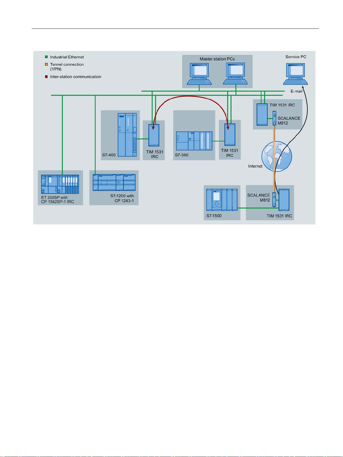
In the sample configuration shown, S7 stations communicate with the master station via the
Ethernet interfaces of the different modules.
With their Ethernet interfaces, TIM modules enable connection to a redundant master
station.
Configuration - DNP3
12 Configuration Manual, 11/2018, C79000-G8976-C508-01
Functions and requirements
E-mails
Inter-station communication
1.2 Configuration examples
Figure 1-1 Communication via Ethernet / Internet
The modules can generate and send e-mails due to events. The following recipients are
possible:
● PCs with an Internet connection
● Cell phones
● SIMATIC stations with the appropriate program blocks
Direct inter-station communication between S7 stations with a TIM is possible via IP-based
networks.
Inter-station communication, in contrast, runs via a master station that forwards the frames to
the target subscriber.
Configuration - DNP3
Configuration Manual, 11/2018, C79000-G8976-C508-01
13
Functions and requirements
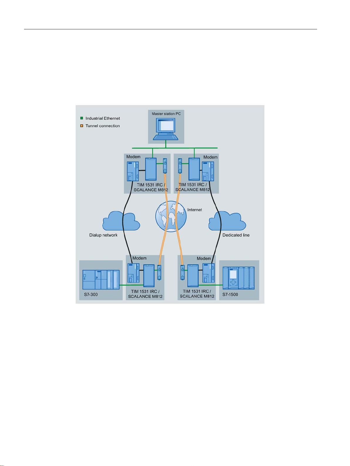
Path redundancy using the serial interface
1.2 Configuration examples
In the following example, the Ethernet interface and the serial interface are used with the
TIM 1531 IRC to set up redundant transmission paths.
● Ethernet interface for communication via Ethernet / Internet
● Serial interface for communication via a WAN network (dedicated line or dialup network)
Figure 1-2 Communication via redundant paths
Path redundancy is also possible over two Ethernet networks.
Configuration - DNP3
14 Configuration Manual, 11/2018, C79000-G8976-C508-01

Functions and requirements
1.3
Usable CPUs
Compatible CPUs
TIM 1531 IRC
CP 1243-1 / CP 1243-8 IRC
CP 1542SP-1 IRC
1.4
Software requirements
Software for configuration and online functions
1.3 Usable CPUs
The following can be configured as assigned CPUs of the communications modules:
●
– S7-1500
All CPUs as of firmware version V2.1
– S7-300
All CPUs with PROFINET interface
– S7-400
All CPUs with PROFINET interface
●
CPU with firmware version as of V4.2
●
CPUs as of firmware version V2.0:
– CPU 1510SP-1 PN
– CPU 1510SP F-1 PN
– CPU 1512SP-1 PN
– CPU 1512SP F-1 PN
You will find more detailed information on the CPUs and the BusAdapters in the manual
/5/ (Page 188).
To configure the modules, the following configuration tool is required:
● STEP 7 Professional V15.1
Configuration - DNP3
Configuration Manual, 11/2018, C79000-G8976-C508-01
15

Functions and requirements
1.5
Performance data and configuration limits
1.5.1
TIM 1531 IRC
Connection resources
Telecontrol connections
E-mail
S7 connections
PG/OP connections
PG routing
Online functions
HTTP/HTTPS
Number of data points for the data point configuration
Message memory: Send buffer / SD card
1.5 Performance data and configuration limits
●
The number of connections or communications partners is limited for the two interface
types and every individual interface.
Note that redundant connection paths of a connection between two partners require two
connection resources on each partner.
– Max. number of connections: 128
Distribution over 4 interfaces can take place in any way (max. 128 per interface).
●
A connection to send e-mails can be established during runtime.
●
– Max. 4 connection resources for PG/OP connections (see below)
●
4 connection resources for connections to the engineering station or HMI devices
(included in the configuration limits of the S7 connections, see above)
●
Max. 4 connections at the same time
●
See PG/OP connections
●
Max. 2 connections per Ethernet interface
The maximum number of configurable data points is 3000.
The TIM has a frame memory (send buffer) for the values of data points configured as an
event.
The send buffer has the following maximum size (number of events):
● 250000
The size of the frame memory is divided equally among all configured communications
partners.
Configuration - DNP3
16 Configuration Manual, 11/2018, C79000-G8976-C508-01

Functions and requirements
Messages: E-mail
1.5.2
TIM 4R-IE DNP3 / TIM 3V-IE DNP3
Number of DNP3 connections
TIM configured as DNP3 master station / node station
TIM 4R-IE DNP3
TIM 3V-IE DNP3
TIM configured as DNP3 station
TIM 4R-IE DNP3
1.5 Performance data and configuration limits
You will find details of how the send buffer works (storing and sending events) as well as the
options for transferring data in the section Process image, type of transmission, event
classes (Page 113).
For information on saving events on an optional SD card, see section Basic settings
(Page 33).
Up to 10 messages which the TIM can send as e-mails can be configured in STEP 7.
● Number of characters per e-mail
Maximum number of characters that can be transferred per e-mail: 256 ASCII characters
including any value sent at the same time
You will find the connection resources in the form of the table after the following listing.
●
Number in total: Max. 128,
of which:
– Pro Ethernet interface:
- Configured with master station function: Max. 64
- Configured with station function: Max. 16
– Pro RS-232 interface:
- Configured with master station function: Max. 32
- Configured with station function: Max. 16
●
Number in total: Max. 8,
of which:
– Via the Ethernet interface: Max. 8
– Via the RS-232 interface: Max. 8
●
Number in total: Max. 32,
of which:
– Per Ethernet interface Max. 16
– Per RS-232 interface: Max. 16
Configuration - DNP3
Configuration Manual, 11/2018, C79000-G8976-C508-01
17

Functions and requirements
TIM 3V-IE DNP3
Note
Double the connection resources with direct communication between stations (only via
Ethernet or dial-up network)
Note that when there is direct communication between two stations, 2 connection
are occupied per station: One for the master station connection, one for the station
connection.
TIM type
Subscriber type /
interface configuration
Max. number of
connections per
TIM in total
Interface
Network type
Max. number of
connections per
interface
Ethernet 1
TCP
64
Ethernet 2
TCP
64
Dedicated line
32
Dialup network
32
Dedicated line
32
Dialup network
32
Ethernet 1
TCP
16
Ethernet 2
TCP
16
Dedicated line
16
Dialup network
16
Dedicated line
16
Dialup network
16
Ethernet
TCP
8
Dialup network
8
Dedicated line
8
Dialup network
8
*
obtained from the information in the "Master station" or "Station" rows.
Number of communications objects per TIM
1.5 Performance data and configuration limits
●
Number in total: Max. 8,
of which:
– Via the Ethernet interface: Max. 8
– Via the RS-232 interface: Max. 8
resources
Table 1- 2 Overview of the connection resources
TIM 4R-IE DNP3 Master station 128 *
RS232 no. 1
RS232 no. 2
Station 32
RS232 no. 1
RS232 no. 2
TIM 3V-IE DNP3 Master station /
node station
Station 8 Ethernet TCP 8
The total number of 128 also applies to the TIM 4R IE DNP3 as a node station. The maximum number per interface is
8
RS232 Dedicated line 8
RS232
The maximum number of communications objects for DNP3 communication per TIM is 100.
Configuration - DNP3
18 Configuration Manual, 11/2018, C79000-G8976-C508-01

Functions and requirements
Size of the message memory for events
Number of S7 connections via Ethernet
TIM 4R-IE DNP3
TIM 3V-IE DNP3
Number of MODBUS slaves per station
1.5.3
CP 1243-8 IRC
Number of CMs/CPs per station
1.5 Performance data and configuration limits
● TIM 3V-IE DNP3: 64 000 events
● TIM 4R-IE DNP3: 200 000 events
In addition to the DNP3 connections, the number of possible S7 connections via the Ethernet
interface is as follows:
●
Number in total: Max. 5,
of which:
– 2 configurable S7 connections
– 2 PG connections
– 1 OP connection
●
Number in total: Max. 3,
of which:
– 2 PG connections
– 1 OP connection
No S7 connections can be established via the serial interface.
The maximum number of MODBUS slaves that can be connected to the serial interface of a
TIM depends on the configured interface standard:
● RS-232: Maximum of 1 MODBUS slave
● RS-485: Maximum of 8 MODBUS slaves
In each S7-1200 station, up to three CMs/CPs can be plugged in and configured, of which a
maximum of one CP 1243-8 IRC.
Configuration - DNP3
Configuration Manual, 11/2018, C79000-G8976-C508-01
19

Functions and requirements
Connection resources
Telecontrol connections
TCP connections
Online functions
S7 connections
S7 routing
PG/OP connections
Number of data points for the data point configuration
Frame memory (send buffer)
Messages: E-mail
IPsec tunnel (VPN)
1.5 Performance data and configuration limits
●
The CP can establish connections to up to 4 communications partners.
The partners can be linked redundantly.
●
The CP can establish connections to up to 4 communications partners (S7 stations).
●
1 connection resource is reserved for online functions.
●
8 connection resources for S7 connections (BSEND/BRCV)
●
Max. 4 connections at the same time
●
– 2 connection resources for PG connections
– 1 connection resource for OP connections
The maximum number of configurable data points is 200.
The CP has a frame memory (send buffer) for the values of data points configured as an
event.
The send buffer has a maximum size of 64000 events. The size of the frame memory is
divided equally among all configured communications partners. It can be set in STEP 7, refer
to the section Communication with the CPU (Page 62).
You will find details of how the send buffer works (storing and sending events) as well as the
options for transferring data in the section Process image, type of transmission, event
classes (Page 113).
Up to 10 messages to be sent as e-mails can be configured in STEP 7.
● Maximum number of characters that can be transferred per e-mail: 256 ASCII characters
including any value sent at the same time
Up to 8 IPsec terminals can be established for secure communication with other security
modules.
Configuration - DNP3
20 Configuration Manual, 11/2018, C79000-G8976-C508-01

Functions and requirements
Firewall rules
1.5.4
CP 1243-1
Number of CMs/CPs per station
Connection resources
Telecontrol connections
S7 connections and TCP / UDP / ISO-on-TCP connections
Online functions
PG/OP connections
Number of data points for the data point configuration
Frame memory (send buffer)
1.5 Performance data and configuration limits
The maximum number of firewall rules in advanced firewall mode is limited to 256.
The firewall rules are divided up as follows:
● Maximum 226 rules with individual addresses
● Maximum 30 rules with address ranges or network addresses
(e.g. 140.90.120.1 - 140.90.120.20 or 140.90.120.0/16)
● Maximum 128 rules with limitation of the transmission speed ("Bandwidth limitation")
In each S7-1200 station, up to three CMs/CPs can be plugged in and configured; this allows
three CP 1243-1 modules.
To use telecontrol communication, three CP 1243-1 modules can be plugged in per station.
●
The CP can establish connections to the following master station types:
– To up to four non-redundant or redundant connected masters
●
Max. 14 connection resources, can be distributed as required for:
– S7 connections (PUT/GET)
– Connections via program blocks (OUC) to S7 stations
●
1 connection resource is reserved for online functions.
●
– 1 connection resource for PG connections
– 3 connection resources for OP connections
The maximum number of configurable data points is 200.
The CP has a frame memory (send buffer) for the values of data points configured as an
event and that are sent to the communications partner.
Configuration - DNP3
Configuration Manual, 11/2018, C79000-G8976-C508-01
21

Functions and requirements
Messages (e-mail)
IPsec tunnel (VPN)
Firewall rules
1.5.5
CP 1542SP-1 IRC
Number of CPs per station
Connection resources
Connection resources
1.5 Performance data and configuration limits
The send buffer has a maximum size of 64000 events divided into equal parts for all
configured communications partners. The size of the frame memory can be set in STEP 7,
refer to the section Process image, type of transmission, event classes (Page 113).
● Sending of up to 10 messages (e-mails) can be configured with the message editor.
● Sending e-mails via the TMAIL_C program block
Up to 8 IPsec terminals can be established for secure communication with other security
modules.
The maximum number of firewall rules in advanced firewall mode is limited to 256.
The firewall rules are divided up as follows:
● Maximum 226 rules with individual addresses
● Maximum 30 rules with address ranges or network addresses
(e.g. 140.90.120.1 - 140.90.120.20 or 140.90.120.0/16)
● Maximum 128 rules with limitation of the transmission speed ("Bandwidth limitation")
In each ET 200SP station, up to three special modules can be plugged in and configured;
this allows a maximum of two CP 154xSP-1 modules.
For details of the permitted special modules and the slot rules, refer to the manual.
Number of connections via Industrial Ethernet, maximum of 32 in total, of which:
● S7: Max. 16
● TCP/IP: Max. 32
● ISO-on-TCP: Max. 32
● UDP: Max. 32
Configuration - DNP3
22 Configuration Manual, 11/2018, C79000-G8976-C508-01

Functions and requirements
Also:
Telecontrol
Telecontrol connections
E-mail (via message editor)
Frame memory (send buffer)
Data points
1.6
PG routing
PG routing between telecontrol modules
1.6 PG routing
● Online connections of the engineering station (STEP 7): Max. 2
● TCP connections for HTTP
For HTTP access upp to 12 TCP connection resources are available that are used by one
or more Web browsers to display data of the CP.
● PG/OP connections (HMI): In total maximum of 16,
of which:
– Connection resources for PG connections: Max. 16
– Connection resources for OP connections: Max. 16
●
Connections to up to four single or redundant masters can be established.
●
Up to 10 e-mails to be sent can be configured.
Maximum number of characters that can be transferred per e-mail: 256 ASCII characters
including any value sent at the same time
●
The CP has a frame memory (send buffer) for the values of data points configured as an
event.
The volume of the send buffer is divided equally among all configured communications
partners. The size of the send buffer can be configured in STEP 7, refer to the section
Communication with the CPU (Page 62).
The maximum size of the send buffer is:
100000 events
You will find details of how the send buffer works such as storing events as well as the
options for transferring the data in the section Process image, type of transmission, event
classes (Page 113).
●
The maximum number of configurable data points is 500.
PG routing is supported between the modules listed in the table and via the specified media.
A requirement is that the options "S7 communication" and "Online functions" are enabled in
the "Communication types" parameter group.
Configuration - DNP3
Configuration Manual, 11/2018, C79000-G8976-C508-01
23

Functions and requirements
Module
Medium
TIM 1531 IRC
CP 1243-8 IRC
CP 1542SP-1 IRC
TIM 1531 IRC
Ethernet (S7)
Ethernet (S7)
Ethernet (S7)
CP 1243-8 IRC
- -
CP 1542SP-1 IRC
Ethernet (S7) - -
1.6 PG routing
Ethernet (S7)
Max. number of S7 routing connections: 4
Configuration - DNP3
24 Configuration Manual, 11/2018, C79000-G8976-C508-01

2
2.1
Addressing and network configuration
Address information of the station
Address information of the master
The following station information is required for the configuration:
● Station address (DNP3 address) of the station
● Listener port of the station. The master needs the port number to establish the
connection.
● Address of the station
– IP address
or
– Name that can be resolved with DNS
If you use DNS, there must be a DNS server (see below) and this must be reachable
for the module.
● DNS server address(es)
You require the DNS server address if you address the master using a name that can be
resolved by DNS.
● Partner number
Masters that communicate with a station require the partner number of the station in
order to assign the data points to be transferred.
With S7-1200 CPs that can only function as stations, the partner number of the master is
assigned by the system.
The following information on the master is required for the configuration:
● Station address of the master
● Listener port of a third-party device with the function "Master"
● Address of the master
– IP address
or
– Name that can be resolved with DNS
If you use DNS, there must be a DNS server (see below) and this must be reachable
for the module.
Configuration - DNP3
Configuration Manual, 11/2018, C79000-G8976-C508-01
25

Communication mechanisms
Redundant masters
Configurations with connections over the Internet: VPN connections
2.2
Communications options
Communication paths
2.2 Communications options
● DNS server address(es)
You require the DNS server address if you address the master using a name that can be
resolved by DNS.
● Partner number
Stations that communicate with the master require the partner number of the master in
order to assign the data points to be transferred.
With S7-1200 CPs that can only function as stations, the partner number of the master is
assigned by the system.
The two devices of a redundant master have an identical station address.
They only require different IP addresses or host names.
For connections running via the Internet, dynamic IP addresses can be used.
To allow communication in both directions and to ensure that the data is protected during
transfer, a connection with a VPN tunnel is necessary. For this the security modules of the
SCALANCE S or SCALANCE M series are available.
Remember the following points when configuring:
● You configure the IP address of the master station on the master.
● When configuring the interface of the station module, you configure the IP address of the
router.
● You perform the VPN configuration with SCALANCE S/M both for the station and for the
master station in STEP 7.
The following communication channels are possible:
● Connections between master and station
● Redundant connections
If two subscribers can be reached via different networks, you can create a maximum of
two connections between the subscribers to establish path redundancy.
Configuration - DNP3
26 Configuration Manual, 11/2018, C79000-G8976-C508-01

Communication mechanisms
2.3
Connection establishment
Connection establishment with DNP3
Note
Connection interrupted by the mobile wireless network provider
When using mobile wireless services, remember that existing connections can be interrupted
by mobile wireless network providers for maintenance p
Spontaneous mode
Connection establishment in Open User Communication and PG/OP communication
2.3 Connection establishment
● Direct communication
With direct communication, stations communicate directly with each other without the
frames being transmitted from a master station or station. Two stations can thus
communicate directly with each other.
You define the function when configuring a data point via the "Master function"
parameter, see section "General" tab (Page 112).
As a further requirement, the "Spontaneous" option must be activated in the telecontrol
connection.
The function is supported by the following modules:
– TIM 1531 IRC as of firmware V2.0
– TIM 3V-IE DNP3 / TIM 4R-IE DNP3 as of firmware V3.2
With the DNP3 protocol, the master establishes the connection (call operation / polling).
If an established connection is interrupted, a master module tries to re-establish the
connection.
urposes.
Enabling the "Unsolicited reporting" parameter in the "Unsolicited responses" parameter
group in the "Settings DNP3 station" of an interface enables the unsolicited transmission of
data from a station. In this case, dial-up network connections can be established by the
communications module as client in order to send data of events spontaneously.
In Open User Communication in an S7 station, the CPU is the connection partner.
Connections are established as soon as the corresponding program blocks are called on the
CPU.
This also applies to the situation when a different S7 station sends data. In this case, the
receiver station calls the corresponding receiver modules.
Configuration - DNP3
Configuration Manual, 11/2018, C79000-G8976-C508-01
27

Communication mechanisms
2.4
Acknowledgment
Acknowledgment in DNP3
Acknowledgment in Open User Communication
2.4 Acknowledgment
The receipt of sent frames is monitored and acknowledged differently depending on the
communication type and the telecontrol protocol.
The basic acknowledgment mechanisms are configured for the data link layer, see section
Transmission settings – DNP3 (Page 53).
A station module acknowledges a request from the master with its response frames.
The acknowledgment of unsolicited frames that a station module sends to the master is
configured in the "Settings DNP3 station" parameter group, see section Settings DNP3
station (Page 56).
The successful sending and receipt of frames is indicated by status displays of the program
blocks.
With TCP segments, the protocol-specific acknowledgement mechanisms are used.
Configuration - DNP3
28 Configuration Manual, 11/2018, C79000-G8976-C508-01

3
3.1
Security recommendations
General
Physical access
Network attachment
Observe the following security recommendations to prevent unauthorized access to the
system.
● You should make regular checks to make sure that the device meets these
recommendations and other internal security guidelines if applicable.
● Evaluate your plant as a whole in terms of security. Use a cell protection concept with
suitable products.
● Do not connect the device directly to the Internet. Operate the device within a protected
network area.
● Keep the firmware up to date. Check regularly for security updates of the firmware and
● Check regularly for new features on the Siemens Internet pages.
Restrict physical access to the device to qualified personnel.
Do not connect the module directly to the Internet. If a connection of the module to the
Internet is required, use the security variants of the telecontrol protocols or use protection
mechanisms in front of the module. Protection mechanisms are for example a SCALANCE M
router or a SCALANCE S security module with firewall.
use them.
– You can find information on Industrial Security here:
Link: (http://www.siemens.com/industrialsecurity)
– You can find information on security in industrial communication here:
Link: (http://w3.siemens.com/mcms/industrial-communication/en/ie/industrial-ethernet-
security/Seiten/industrial-security.aspx)
– You will find a publication on the topic of network security (6ZB5530-1AP0x-0BAx)
here:
Link:
(http://w3app.siemens.com/mcms/infocenter/content/en/Pages/order_form.aspx?node
Key=key_518693&infotype=brochures)
Enter the following filter: 6ZB5530
Configuration - DNP3
Configuration Manual, 11/2018, C79000-G8976-C508-01
29

Configuration
Security functions of the product
Passwords
Protocols
Secure and non-secure protocols
Table: Meaning of the column titles and entries
Protocol / function
Port number (protocol)
3.1 Security recommendations
Use the options for security settings in the configuration of the product. These includes
among others:
● Protection levels
Configure a protection level of the CPU.
You will find information on this in the information system of STEP 7.
● Security function of the communication
– Using the security functions of the telecontrol protocols.
– Use the secure protocol variants, for example NTP (secure) or SNMPv3.
– Leave access to the Web server deactivated.
● Define rules for the use of devices and assignment of passwords.
● Regularly update the passwords to increase security.
● Only use passwords with a high password strength. Avoid weak passwords for example
"password1", "123456789" or similar.
● Make sure that all passwords are protected and inaccessible to unauthorized personnel.
See also the preceding section for information on this.
● Do not use one password for different users and systems.
● Only activate protocols that you require to use the system.
● Use secure protocols when access to the device is not prevented by physical protection
measures.
– The NTP protocol provides a secure alternative with NTP (secure).
– The HTTP protocol provides a secure alternative with HTTPS when accessing the
Web server.
● Deactivate DHCP at interfaces to public networks such as the Internet, for example, to
prevent IP spoofing.
The following table provides you with an overview of the open ports on this device.
●
Protocols that the device supports.
●
Port number assigned to the protocol.
Configuration - DNP3
30 Configuration Manual, 11/2018, C79000-G8976-C508-01
 Loading...