

Siemens SIMATIC TD 200 User Manual

Preface, Contents
SIMATIC
TD 200
Operator Interface
User Manual
This manual has the order number:
6ES7272-0AA00-8BA0
Product Overview and
Installation
Configuring the TD 200
Operating the TD 200
Creating Sample
Programs
Specifications and
Reference
Multiple CPU Configura-
tions
Troubleshooting
TD 200 Parameters and
Messages
1
2
3
4
A
B
C
D
Index

Safety Guidelines
!
!
!
This manual contains notices which you should observe to ensure your own personal safety,
as well as to protect the product and connected equipment. These notices are highlighted in
the manual by a warning triangle and are marked as follows according to the level of danger:
Danger
indicates that death, severe personal injury, or substantial property damage will result if proper
precautions are not taken.
Warning
indicates that death, severe personal injury, or substantial property damage can result if proper
precautions are not taken.
Caution
indicates that minor personal injury or property damage can result if proper precautions are not
taken.
Qualified Personnel
Correct Usage
!
Trademarks
The device/system may only be set up and operated in conjunction with this manual.
Only qualified personnel should be allowed to install and work on this equipment.
Qualified persons are defined as persons who are authorized to commission, to ground, and
to tag circuits, equipment, and systems in accordance with established safety practices and
standards.
Note the following:
Warning
This device and its components may only be used for the applications described in the catalog
or the technical description, and only in connection with devices or components from other
manufacturers which have been approved or recommended by Siemens.
This product can only function correctly and safely if it is transported, stored, set up, and
installed correctly, and operated and maintained as recommended.
SIMATIC, SIMATIC NET and SIMATIC HMI are registered trademarks of
Siemens AG.
Disclaimer of LiabilityCopyright Siemens AG 1997 All rights reserved.
The reproduction, transmission, or use of this document or its
contents is not permitted without express written authority.
Offenders will be liable for damages. All rights, including rights
created by patent grant or registration of a utility model or design, are
reserved.
Siemens AG
Bereich Automatisierungs- und Antriebstechnik
Geschaeftsgebiet Industrie-Automatisierungssysteme
Postfach 4848, D-90327 Nuernberg
Siemens Aktiengesellschaft 6ES7272-0AA00-8BA0
We have checked the contents of this manual for agreement with the
hardware and software described. Since deviations cannot be
precluded entirely , we cannot guarantee full agreement. However ,
the data in this manual are reviewed regularly and any necessary
corrections included in subsequent editions. Suggestions for
improvement are welcomed.
Siemens AG 1997
Technical data subject to change.

Preface
Purpose
SIMATIC TD 200 Operator Interface User Manual
The
manual that describes the operation of the TD 200 Operator Interface Module with an S7-200
programmable logic controller.
Audience
This manual is designed for engineers, programmers, and maintenance personnel who have
a general knowledge of programmable logic controllers and operator interfaces.
Scope of This Manual
This manual describes the operation of version 1.1 and later of the TD 200. This release
includes new features and other operational enhancements.
Release Notes
Version 1.1 of the TD 200 includes the following new features:
S Supports real (floating-point) numbers
S Provides password protection for editable variables and for the Menu mode of operation
S Supports multiple parameter blocks in a single S7-200 CPU (with a setup menu for
entering the V memory address)
S Supports 19.2 Kbaud communication rate (with a setup menu for changing the baud rate)
S Sets a bit in the parameter block every time an arrow key is pressed, thus allowing your
program to have more control of the TD 200
S Includes an alternative character set for creating bar charts
Other enhancements (such as using any key—not just the ESC key—to cancel the scrolling
of the messages, or using SHIFT-ENTER to set a variable to 0) either improve the
performance of the TD 200 or make it easier to use. For example, you can now use the
SHIFT-UP/DOWN arrow keys to perform a character-by-character edit of a variable that is
embedded in a message.
Version 1.2 of the TD 200 includes the following new features:
S Corrects problems with multi-master networks
S Makes the editors more consistent
For upgrades to version 1.2 of the TD 200, contact your distributor.
is a combination user and reference
SIMATIC TD 200 Operator Interface
C79000-G7076-C205-04
iii

Preface
Agency Approvals
The SIMA TIC S7-200 series meets the standards and regulations of the following agencies.
S Underwriters Laboratories, Inc.:
UL 508 Listed
(Industrial Control Equipment)
S Canadian Standards Association:
CSA C22.2 Number 142 Certified
(Process Control Equipment)
S European Community EMC Directive 89/336/EEC and Low Voltage Directive 73/23/EEC
How to Use This Manual
If this is your first experience using an operator interface, read the entire manual. If you are
an experienced user, refer to the Table of Contents or Index to find specific information.
Related Information
Refer to the following documentation for more detailed information about selected topics:
S
SIMA TIC S7-200 Programmable Controller System Manual:
installing and programming the S7-200 Micro PLCs, including the following topics:
– Installing and wiring the S7-200 CPU and expansion I/O modules, and installing the
STEP 7–Micro/WIN software
– Designing and entering a program
– Understanding features of the CPU, such as data types and addressing modes, the
CPU scan cycle, password-protection, and network communication
This manual also includes descriptions and examples for the programming instructions,
typical execution times for the instructions, and the data sheets for the S7-200
equipment.
S
SIMATIC STEP 7–Micro/DOS User Manual:
STEP 7–Micro/DOS programming software package for the SIMATIC S7-200 series of
programmable logic controllers.
provides information about
describes how to use the
iv
SIMATIC TD 200 Operator Interface
C79000-G7076-C205-04

Contents
1 Product Overview and Installation
Chapter Overview 1-1. . . . . . . . . . . . . . . . . . . . . . . . . . . . . . . . . . . . . . . . . . . . . . . . . . . . . .
1.1 Hardware Features 1-2. . . . . . . . . . . . . . . . . . . . . . . . . . . . . . . . . . . . . . . . . . . . . . . . . . . . .
Components of the TD 200 1-2. . . . . . . . . . . . . . . . . . . . . . . . . . . . . . . . . . . . . . . . . . . . . . .
TD 200 Keyboard Features 1-3. . . . . . . . . . . . . . . . . . . . . . . . . . . . . . . . . . . . . . . . . . . . . .
1.2 Installing the TD 200 1-4. . . . . . . . . . . . . . . . . . . . . . . . . . . . . . . . . . . . . . . . . . . . . . . . . . . .
Preparing the Mounting Surface 1-4. . . . . . . . . . . . . . . . . . . . . . . . . . . . . . . . . . . . . . . . . .
Preparing the TD 200 for Mounting 1-4. . . . . . . . . . . . . . . . . . . . . . . . . . . . . . . . . . . . . . . .
Mounting the TD 200 1-5. . . . . . . . . . . . . . . . . . . . . . . . . . . . . . . . . . . . . . . . . . . . . . . . . . . .
1.3 Connecting the Communication Cable 1-6. . . . . . . . . . . . . . . . . . . . . . . . . . . . . . . . . . . . .
Installing Cable for One-to-One Communication 1-6. . . . . . . . . . . . . . . . . . . . . . . . . . . . .
Installing a Multiple CPU Network 1-6. . . . . . . . . . . . . . . . . . . . . . . . . . . . . . . . . . . . . . . . .
1.4 Connecting a Power Cable 1-7. . . . . . . . . . . . . . . . . . . . . . . . . . . . . . . . . . . . . . . . . . . . . . .
Supplying Power from the S7-200 CPU 1-7. . . . . . . . . . . . . . . . . . . . . . . . . . . . . . . . . . . .
Supplying Power from an External Power Supply 1-7. . . . . . . . . . . . . . . . . . . . . . . . . . . .
2 Configuring the TD 200
Chapter Overview 2-1. . . . . . . . . . . . . . . . . . . . . . . . . . . . . . . . . . . . . . . . . . . . . . . . . . . . . .
2.1 Starting the STEP 7–Micro/WIN TD 200 Configuration Wizard 2-2. . . . . . . . . . . . . . . .
Selecting Language and Bar Graph Character Set 2-3. . . . . . . . . . . . . . . . . . . . . . . . . . .
Enabling Time-of-Day, Force Function, and Password Protection 2-4. . . . . . . . . . . . . .
Specifying Function Key Memory Bits and Display Update Rate 2-4. . . . . . . . . . . . . . .
Selecting Message Size and Number of Messages 2-6. . . . . . . . . . . . . . . . . . . . . . . . . .
Specifying Parameter Block Address, Message Enable Address, and
Message Location 2-7. . . . . . . . . . . . . . . . . . . . . . . . . . . . . . . . . . . . . . . . . . . . . . . . . . . . . .
Creating A Text-Only Message 2-8. . . . . . . . . . . . . . . . . . . . . . . . . . . . . . . . . . . . . . . . . . .
Embedding Data Values in a Text Message 2-9. . . . . . . . . . . . . . . . . . . . . . . . . . . . . . . . .
Formatting the Embedded Data Value 2-1 1. . . . . . . . . . . . . . . . . . . . . . . . . . . . . . . . . . . . .
Creating a Message That Requires Acknowledgement 2-14. . . . . . . . . . . . . . . . . . . . . . .
Viewing the TD 200 Parameter Block and Messages 2-17. . . . . . . . . . . . . . . . . . . . . . . .
2.2 Creating a Sample Program 2-18. . . . . . . . . . . . . . . . . . . . . . . . . . . . . . . . . . . . . . . . . . . . . .
3 Operating the TD 200
Chapter Overview 3-1. . . . . . . . . . . . . . . . . . . . . . . . . . . . . . . . . . . . . . . . . . . . . . . . . . . . . .
3.1 Using the Display Message Mode 3-2. . . . . . . . . . . . . . . . . . . . . . . . . . . . . . . . . . . . . . . . .
Functions Available 3-2. . . . . . . . . . . . . . . . . . . . . . . . . . . . . . . . . . . . . . . . . . . . . . . . . . . . .
Scrolling through Messages 3-2. . . . . . . . . . . . . . . . . . . . . . . . . . . . . . . . . . . . . . . . . . . . . .
Editing a Value 3-3. . . . . . . . . . . . . . . . . . . . . . . . . . . . . . . . . . . . . . . . . . . . . . . . . . . . . . . . .
Acknowledging a Message 3-4. . . . . . . . . . . . . . . . . . . . . . . . . . . . . . . . . . . . . . . . . . . . . . .
3.2 Using the Menu Mode 3-5. . . . . . . . . . . . . . . . . . . . . . . . . . . . . . . . . . . . . . . . . . . . . . . . . . .
Menus Available 3-5. . . . . . . . . . . . . . . . . . . . . . . . . . . . . . . . . . . . . . . . . . . . . . . . . . . . . . . .
Selecting Menu Options 3-5. . . . . . . . . . . . . . . . . . . . . . . . . . . . . . . . . . . . . . . . . . . . . . . . .
Exiting Menu Mode 3-5. . . . . . . . . . . . . . . . . . . . . . . . . . . . . . . . . . . . . . . . . . . . . . . . . . . . .
SIMATIC TD 200 Operator Interface
C79000-G7076-C205-04
v

Contents
3.3 Viewing Messages 3-6. . . . . . . . . . . . . . . . . . . . . . . . . . . . . . . . . . . . . . . . . . . . . . . . . . . . . .
Accessing the Menu 3-6. . . . . . . . . . . . . . . . . . . . . . . . . . . . . . . . . . . . . . . . . . . . . . . . . . . .
3.4 Viewing CPU Status Menu 3-7. . . . . . . . . . . . . . . . . . . . . . . . . . . . . . . . . . . . . . . . . . . . . . .
Accessing the Menu 3-7. . . . . . . . . . . . . . . . . . . . . . . . . . . . . . . . . . . . . . . . . . . . . . . . . . . .
Viewing Fatal and Non-fatal Errors 3-7. . . . . . . . . . . . . . . . . . . . . . . . . . . . . . . . . . . . . . . .
Fatal Error Messages 3-8. . . . . . . . . . . . . . . . . . . . . . . . . . . . . . . . . . . . . . . . . . . . . . . . . . .
Non-fatal Error Messages 3-8. . . . . . . . . . . . . . . . . . . . . . . . . . . . . . . . . . . . . . . . . . . . . . . .
3.5 Forcing I/O 3-9. . . . . . . . . . . . . . . . . . . . . . . . . . . . . . . . . . . . . . . . . . . . . . . . . . . . . . . . . . . . .
Accessing the Menu 3-9. . . . . . . . . . . . . . . . . . . . . . . . . . . . . . . . . . . . . . . . . . . . . . . . . . . .
Entering a Password 3-10. . . . . . . . . . . . . . . . . . . . . . . . . . . . . . . . . . . . . . . . . . . . . . . . . . . .
Correcting a Password 3-10. . . . . . . . . . . . . . . . . . . . . . . . . . . . . . . . . . . . . . . . . . . . . . . . . .
Selecting a Force I/O Option 3-11. . . . . . . . . . . . . . . . . . . . . . . . . . . . . . . . . . . . . . . . . . . . .
Forcing and Unforcing an I/O Point 3-12. . . . . . . . . . . . . . . . . . . . . . . . . . . . . . . . . . . . . . . .
3.6 Setting Time and Date in the CPU 3-13. . . . . . . . . . . . . . . . . . . . . . . . . . . . . . . . . . . . . . . . .
Accessing the Menu 3-13. . . . . . . . . . . . . . . . . . . . . . . . . . . . . . . . . . . . . . . . . . . . . . . . . . . .
Editing the Time and Date 3-14. . . . . . . . . . . . . . . . . . . . . . . . . . . . . . . . . . . . . . . . . . . . . . . .
3.7 Releasing the Password 3-15. . . . . . . . . . . . . . . . . . . . . . . . . . . . . . . . . . . . . . . . . . . . . . . . .
Restoring the Password Protection 3-15. . . . . . . . . . . . . . . . . . . . . . . . . . . . . . . . . . . . . . . .
3.8 Using the TD 200 Setup Menu Option 3-16. . . . . . . . . . . . . . . . . . . . . . . . . . . . . . . . . . . . .
Setting the Network Address of the TD 200 3-16. . . . . . . . . . . . . . . . . . . . . . . . . . . . . . . . .
Selecting the CPU Address 3-17. . . . . . . . . . . . . . . . . . . . . . . . . . . . . . . . . . . . . . . . . . . . . .
Entering the Parameter Block Address 3-18. . . . . . . . . . . . . . . . . . . . . . . . . . . . . . . . . . . . .
Selecting the Baud Rate 3-19. . . . . . . . . . . . . . . . . . . . . . . . . . . . . . . . . . . . . . . . . . . . . . . . .
4 Creating Sample Programs
Chapter Overview 4-1. . . . . . . . . . . . . . . . . . . . . . . . . . . . . . . . . . . . . . . . . . . . . . . . . . . . . .
4.1 Using a Text Message to Create a Clock for a CPU 214 4-2. . . . . . . . . . . . . . . . . . . . . .
Creating a Sample Program 4-2. . . . . . . . . . . . . . . . . . . . . . . . . . . . . . . . . . . . . . . . . . . . . .
Using the STEP 7–Micro/WIN TD 200 Configuration Wizard 4-2. . . . . . . . . . . . . . . . . .
4.2 Using the Bar Graph Character Set 4-5. . . . . . . . . . . . . . . . . . . . . . . . . . . . . . . . . . . . . . .
A Specifications and Reference
Chapter Overview A-1. . . . . . . . . . . . . . . . . . . . . . . . . . . . . . . . . . . . . . . . . . . . . . . . . . . . . .
A.1 Specifications for Model Number 6ES7 272–0AA00–0Y A0 A-2. . . . . . . . . . . . . . . . . . . .
A.2 ASCII Characters A-3. . . . . . . . . . . . . . . . . . . . . . . . . . . . . . . . . . . . . . . . . . . . . . . . . . . . . . .
A.3 AL T Key Combinations for International and Special Characters A-4. . . . . . . . . . . . . . .
B Multiple CPU Configurations
Chapter Overview B-1. . . . . . . . . . . . . . . . . . . . . . . . . . . . . . . . . . . . . . . . . . . . . . . . . . . . . .
B.1 Configuring for Multiple CPU Communication B-2. . . . . . . . . . . . . . . . . . . . . . . . . . . . . . .
B.2 Building a TD/CPU Cable B-4. . . . . . . . . . . . . . . . . . . . . . . . . . . . . . . . . . . . . . . . . . . . . . . .
Making a Cable That Supplies Power to the TD 200 B-4. . . . . . . . . . . . . . . . . . . . . . . . .
Making a Cable That Does Not Supply Power to the TD 200 B-4. . . . . . . . . . . . . . . . . .
C Troubleshooting
D TD 200 Parameters and Messages
Software Support for Configuring a TD 200 D-1. . . . . . . . . . . . . . . . . . . . . . . . . . . . . . . . .
Chapter Overview D-1. . . . . . . . . . . . . . . . . . . . . . . . . . . . . . . . . . . . . . . . . . . . . . . . . . . . . .
SIMATIC TD 200 Operator Interface
vi
C79000-G7076-C205-04

Contents
D.1 TD 200 Parameter Block D-2. . . . . . . . . . . . . . . . . . . . . . . . . . . . . . . . . . . . . . . . . . . . . . . . .
Understanding How Messages Are Displayed D-2. . . . . . . . . . . . . . . . . . . . . . . . . . . . . .
Understanding How the TD 200 Uses the Parameter Block D-2. . . . . . . . . . . . . . . . . . .
Description of the Parameter Block Format D-3. . . . . . . . . . . . . . . . . . . . . . . . . . . . . . . . .
D.2 Building the Parameter Block D-4. . . . . . . . . . . . . . . . . . . . . . . . . . . . . . . . . . . . . . . . . . . . .
Parameter Block ID Bytes 0 and 1 D-4. . . . . . . . . . . . . . . . . . . . . . . . . . . . . . . . . . . . . . . .
TD 200 Configuration Bytes 2 and 3 D-4. . . . . . . . . . . . . . . . . . . . . . . . . . . . . . . . . . . . . . .
Number of Messages Byte 4 D-5. . . . . . . . . . . . . . . . . . . . . . . . . . . . . . . . . . . . . . . . . . . . .
Prioritizing Messages D-6. . . . . . . . . . . . . . . . . . . . . . . . . . . . . . . . . . . . . . . . . . . . . . . . . . . .
M Area Address Byte 5 D-6. . . . . . . . . . . . . . . . . . . . . . . . . . . . . . . . . . . . . . . . . . . . . . . . . .
Message Address Bytes 6 and 7 D-7. . . . . . . . . . . . . . . . . . . . . . . . . . . . . . . . . . . . . . . . . .
Message-Enable Address Bytes 8 and 9 D-7. . . . . . . . . . . . . . . . . . . . . . . . . . . . . . . . . . .
Edit Password Byte 10 and 11 (Optional) D-8. . . . . . . . . . . . . . . . . . . . . . . . . . . . . . . . . . .
D.3 Formatting Messages D-9. . . . . . . . . . . . . . . . . . . . . . . . . . . . . . . . . . . . . . . . . . . . . . . . . . .
Twenty-Character Message Format D-9. . . . . . . . . . . . . . . . . . . . . . . . . . . . . . . . . . . . . . .
Forty-Character Message Format D-10. . . . . . . . . . . . . . . . . . . . . . . . . . . . . . . . . . . . . . . . .
D.4 Embedding Data Values in a Text Message D-11. . . . . . . . . . . . . . . . . . . . . . . . . . . . . . . . .
Data Value Format Options D-11. . . . . . . . . . . . . . . . . . . . . . . . . . . . . . . . . . . . . . . . . . . . . .
Defining the Data Value Format D-12. . . . . . . . . . . . . . . . . . . . . . . . . . . . . . . . . . . . . . . . . . .
Acknowledgement Bit 0 D-12. . . . . . . . . . . . . . . . . . . . . . . . . . . . . . . . . . . . . . . . . . . . . . . . . .
Acknowledge-Notification Bit 1 D-13. . . . . . . . . . . . . . . . . . . . . . . . . . . . . . . . . . . . . . . . . . . .
Edit-Notification Bit 2 D-14. . . . . . . . . . . . . . . . . . . . . . . . . . . . . . . . . . . . . . . . . . . . . . . . . . . .
Password Protection Bit 3 D-16. . . . . . . . . . . . . . . . . . . . . . . . . . . . . . . . . . . . . . . . . . . . . . . .
Edit-Allowed Bit 4 D-16. . . . . . . . . . . . . . . . . . . . . . . . . . . . . . . . . . . . . . . . . . . . . . . . . . . . . . .
Data Size/Format, and Decimal Bits 0, 1, 2 and 4, 5, 6 D-17. . . . . . . . . . . . . . . . . . . . . . .
D.5 Understanding Message Types D-20. . . . . . . . . . . . . . . . . . . . . . . . . . . . . . . . . . . . . . . . . . .
No Acknowledgement, No Edits Allowed D-20. . . . . . . . . . . . . . . . . . . . . . . . . . . . . . . . . . .
Acknowledgement, No Edits Allowed D-20. . . . . . . . . . . . . . . . . . . . . . . . . . . . . . . . . . . . . .
No Acknowledgement, Edits Allowed D-20. . . . . . . . . . . . . . . . . . . . . . . . . . . . . . . . . . . . . .
Acknowledgement, Edits Allowed D-21. . . . . . . . . . . . . . . . . . . . . . . . . . . . . . . . . . . . . . . . .
D.6 Editing Variables with the TD 200 D-22. . . . . . . . . . . . . . . . . . . . . . . . . . . . . . . . . . . . . . . . .
Acknowledging and Editing a Message D-22. . . . . . . . . . . . . . . . . . . . . . . . . . . . . . . . . . . .
Aborting an Edit D-23. . . . . . . . . . . . . . . . . . . . . . . . . . . . . . . . . . . . . . . . . . . . . . . . . . . . . . . .
SIMATIC TD 200 Operator Interface
C79000-G7076-C205-04
vii

Contents
Figures
1-1 Major Components of the TD 200 1-2. . . . . . . . . . . . . . . . . . . . . . . . . . . . . . . . . . . . . . . . .
1-2 Mounting Surface Hole Dimensions 1-4. . . . . . . . . . . . . . . . . . . . . . . . . . . . . . . . . . . . . . .
1-3 Removing the Three Mounting Screws 1-4. . . . . . . . . . . . . . . . . . . . . . . . . . . . . . . . . . . . .
1-4 Positioning Spacers 1-5. . . . . . . . . . . . . . . . . . . . . . . . . . . . . . . . . . . . . . . . . . . . . . . . . . . . .
1-5 One-to-One Configuration 1-6. . . . . . . . . . . . . . . . . . . . . . . . . . . . . . . . . . . . . . . . . . . . . . . .
1-6 Supplying Power with the TD/CPU Cable 1-7. . . . . . . . . . . . . . . . . . . . . . . . . . . . . . . . . .
1-7 Supplying Power Using an External Power Supply 1-7. . . . . . . . . . . . . . . . . . . . . . . . . .
2-1 Accessing the TD 200 Configuration Wizard 2-2. . . . . . . . . . . . . . . . . . . . . . . . . . . . . . . .
2-2 Wizard: Language and Character Set 2-3. . . . . . . . . . . . . . . . . . . . . . . . . . . . . . . . . . . . . .
2-3 Wizard: Time-of-Day Clock, Force I/O, and Password Protection 2-4. . . . . . . . . . . . . .
2-4 Bits Set by Each Function Key 2-5. . . . . . . . . . . . . . . . . . . . . . . . . . . . . . . . . . . . . . . . . . . .
2-5 Wizard: Function Key Memory Bits and Update Rate 2-5. . . . . . . . . . . . . . . . . . . . . . . .
2-6 Wizard: Message Size and Number of Messages 2-6. . . . . . . . . . . . . . . . . . . . . . . . . . .
2-7 Wizard: Block Address, Enable Flags, and Message Location 2-7. . . . . . . . . . . . . . . . .
2-8 Wizard: 40-Character Message 2-8. . . . . . . . . . . . . . . . . . . . . . . . . . . . . . . . . . . . . . . . . . .
2-9 Wizard: Embedding Variable Data Value in a Message 2-10. . . . . . . . . . . . . . . . . . . . . . .
2-10 TD 200 Message: Creating a Word Embedded Data 2-1 1. . . . . . . . . . . . . . . . . . . . . . . . .
2-1 1 Wizard: Embedded Data Value Place Holder in Message 2-12. . . . . . . . . . . . . . . . . . . . .
2-12 Embedded Data: Making the Data Editable and Password Protected. 2-13. . . . . . . . . .
2-13 Wizard: Completed Second Message 2-13. . . . . . . . . . . . . . . . . . . . . . . . . . . . . . . . . . . . . .
2-14 Wizard: Embedding Data to Require Acknowledgement 2-14. . . . . . . . . . . . . . . . . . . . . .
2-15 Embedded Data: Requiring Acknowledgement of Message 2-15. . . . . . . . . . . . . . . . . . .
2-16 Wizard: Message Requires Acknowledgement 2-16. . . . . . . . . . . . . . . . . . . . . . . . . . . . . .
2-17 Data Block Editor Showing a Sample TD 200 Parameter Block 2-17. . . . . . . . . . . . . . . .
2-18 Sample Program in the Ladder and Statement List Editors 2-19. . . . . . . . . . . . . . . . . . . .
3-1 Display Message Mode 3-2. . . . . . . . . . . . . . . . . . . . . . . . . . . . . . . . . . . . . . . . . . . . . . . . . .
3-2 Menu Mode 3-5. . . . . . . . . . . . . . . . . . . . . . . . . . . . . . . . . . . . . . . . . . . . . . . . . . . . . . . . . . . .
3-3 Incorrect Password Display 3-10. . . . . . . . . . . . . . . . . . . . . . . . . . . . . . . . . . . . . . . . . . . . . .
3-4 Force I/O Menu Display 3-11. . . . . . . . . . . . . . . . . . . . . . . . . . . . . . . . . . . . . . . . . . . . . . . . . .
3-5 Changing the Force Status of an I/O Point 3-12. . . . . . . . . . . . . . . . . . . . . . . . . . . . . . . . . .
3-6 No Clock in CPU Display 3-13. . . . . . . . . . . . . . . . . . . . . . . . . . . . . . . . . . . . . . . . . . . . . . . .
4-1 Accessing the TD 200 Configuration Wizard 4-2. . . . . . . . . . . . . . . . . . . . . . . . . . . . . . . .
4-2 Data Block of the Clock Message 4-3. . . . . . . . . . . . . . . . . . . . . . . . . . . . . . . . . . . . . . . . .
4-3 Sample Program for Creating a Clock 4-4. . . . . . . . . . . . . . . . . . . . . . . . . . . . . . . . . . . . .
4-4 Data Block of the Bar Graph Sample Program 4-5. . . . . . . . . . . . . . . . . . . . . . . . . . . . . .
4-5 Sample Program for Creating a Bar Graph 4-7. . . . . . . . . . . . . . . . . . . . . . . . . . . . . . . . .
B-1 A Typical Multiple CPU Network B-2. . . . . . . . . . . . . . . . . . . . . . . . . . . . . . . . . . . . . . . . . .
B-2 TD/CPU Cable with Power Connections B-4. . . . . . . . . . . . . . . . . . . . . . . . . . . . . . . . . . .
B-3 TD/CPU Cable without Power Connections B-4. . . . . . . . . . . . . . . . . . . . . . . . . . . . . . . . .
D-1 Displaying Different Messages on T wo TD 200 Units D-2. . . . . . . . . . . . . . . . . . . . . . . . .
D-2 TD 200 Parameter Block D-3. . . . . . . . . . . . . . . . . . . . . . . . . . . . . . . . . . . . . . . . . . . . . . . . .
D-3 Information Contained in Byte 2 of the TD 200 Parameter Block D-4. . . . . . . . . . . . . . .
D-4 Information Contained in Byte 3 of the TD 200 Parameter Block D-5. . . . . . . . . . . . . . .
D-5 Message-Enable Bits for up to 80 Messages D-6. . . . . . . . . . . . . . . . . . . . . . . . . . . . . . .
D-6 Bits Set by Each Function Key D-7. . . . . . . . . . . . . . . . . . . . . . . . . . . . . . . . . . . . . . . . . . . .
D-7 Twenty-Character Message Format D-9. . . . . . . . . . . . . . . . . . . . . . . . . . . . . . . . . . . . . . .
D-8 Forty-Character Message Format D-10. . . . . . . . . . . . . . . . . . . . . . . . . . . . . . . . . . . . . . . . .
D-9 Format Word Usage D-11. . . . . . . . . . . . . . . . . . . . . . . . . . . . . . . . . . . . . . . . . . . . . . . . . . . . .
D-10 Bit Values of the Format Word D-12. . . . . . . . . . . . . . . . . . . . . . . . . . . . . . . . . . . . . . . . . . . .
D-11 Acknowledgement Bit of Byte 0 of the Format Word D-12. . . . . . . . . . . . . . . . . . . . . . . . .
D-12 Acknowledge-Notification Bit of Byte 0 of the Format Word D-13. . . . . . . . . . . . . . . . . . .
D-13 Sample Program for Using the Acknowledge-Notification Bit D-14. . . . . . . . . . . . . . . . . .
D-14 Edit-Notification Bit of Byte 0 of the Format Word D-14. . . . . . . . . . . . . . . . . . . . . . . . . . . .
D-15 Sample Program for Using the Edit-Notification Bit D-15. . . . . . . . . . . . . . . . . . . . . . . . . .
D-16 Password Protection Bit of Byte 0 of the Format Word D-16. . . . . . . . . . . . . . . . . . . . . . .
D-17 Edit-Allowed Bit of Byte 0 of the Format Word D-16. . . . . . . . . . . . . . . . . . . . . . . . . . . . . . .
D-18 Bit Values of Byte 1 of the Format Word D-17. . . . . . . . . . . . . . . . . . . . . . . . . . . . . . . . . . . .
viii
SIMATIC TD 200 Operator Interface
C79000-G7076-C205-04

T ables
1-1 Components of the TD 200 1-2. . . . . . . . . . . . . . . . . . . . . . . . . . . . . . . . . . . . . . . . . . . . . .
1-2 Description of Command Keys 1-3. . . . . . . . . . . . . . . . . . . . . . . . . . . . . . . . . . . . . . . . . . . .
1-3 Description of Function Keys 1-3. . . . . . . . . . . . . . . . . . . . . . . . . . . . . . . . . . . . . . . . . . . . .
A-1 ASCII Characters for the TD 200 A-3. . . . . . . . . . . . . . . . . . . . . . . . . . . . . . . . . . . . . . . . .
A-2 ALT Key Combinations for International and Special Characters A-4. . . . . . . . . . . . . . .
C-1 Troubleshooting Table C-1. . . . . . . . . . . . . . . . . . . . . . . . . . . . . . . . . . . . . . . . . . . . . . . . . . .
D-1 Required Display Characters for Each Display Format D-19. . . . . . . . . . . . . . . . . . . . . . .
Contents
SIMATIC TD 200 Operator Interface
C79000-G7076-C205-04
ix

Contents
x
SIMATIC TD 200 Operator Interface
C79000-G7076-C205-04

Product Overview and Installation
The Text Display 200 (TD 200) is a text display and operator interface for the S7-200 family
of programmable logic controllers. This manual uses the terms programmable logic controller
and S7-200 CPU (or CPU) interchangeably .
The following is a list of TD 200 features:
S Displays messages read from the S7-200 CPU.
S Allows adjustment of designated program variables.
S Provides ability to force/unforce I/O points.
S Provides ability to set the time and date for CPUs that have real-time clocks.
The TD 200 receives its power either from the S7-200 CPU through the TD/CPU cable or
from a separate power supply .
The TD 200 functions as a point-to-point interface (PPI) master when it is connected to one
or more S7-200 CPUs. The TD 200 is also designed to operate with any other PPI master in
a network. Multiple TD 200s can be used with one or more S7-200 CPUs connected to the
same network.
This manual provides you with hardware configuration directions and programming
examples that require additional equipment. The following is a list of additional equipment
that is necessary to set up and use your TD 200:
S S7-200 series programmable logic controller
S S7-200 programming device
S Programming cable appropriate for your programming device
1
Chapter Overview
Section Description Page
1.1 Hardware Features 1-2
1.2 Installing the TD 200 1-4
1.3 Connecting the Communication Cable 1-6
1.4 Connecting a Power Cable 1-7
SIMATIC TD 200 Operator Interface
C79000-G7076-C205-04
1-1

Product Overview and Installation
1.1 Hardware Features
Components of the TD 200
The TD 200 is a small, compact device that provides all the necessary components for
interfacing with your S7-200 CPU. Figure 1-1 shows the major components of the TD 200.
These components are described in Table 1-1. For further information on the technical
specifications of the TD 200, see Appendix A.
Text Display Area
SIEMENS TD 200
F5
F1
F6
F7
F2
F8
F3
F4
SHIFT
ESC ENTER
Communication
Port
Power
Connection
Spacers
User Label
Gasket
TD/CPU Cable
Figure 1-1 Major Components of the TD 200
Table 1-1 Components of the TD 200
Component
Description
Text Display Area The text display area is a backlit liquid crystal display (LCD) with two
20-character lines. It allows you to see messages received from the
S7-200 CPU.
Gasket A gasket is provided with the TD 200 for installation in inclement
environments.
Communication Port The communication port is a 9-pin D-connector that allows you to
connect the TD 200 to an S7-200 CPU using the supplied TD/CPU
cable.
Power Connection You can connect an external power supply to the TD 200 through the
power connection access located on the right side of the TD 200. This
connection is not required when you use the TD/CPU cable.
TD/CPU Cable The TD/CPU cable provides communication and power to your TD 200.
It is a 9-pin, straight-through cable that is supplied with your TD 200.
User Label The user label is a pull-out label that you can use to customize the
function key labels for your applications.
Keys The TD 200 has nine keys. Five of these keys provide predefined,
context-sensitive functions, and four keys provide user-defined functions.
Spacers Self-adhesive spacers are included for mounting the TD 200 to a
mounting surface. See Figure 1-4.
1-2
SIMATIC TD 200 Operator Interface
C79000-G7076-C205-04

TD 200 Keyboard Features
The TD 200 keyboard has a total of nine keys. Table 1-2 describes the five predefined,
context-sensitive command keys.
Table 1-2 Description of Command Keys
Product Overview and Installation
Command Keys
ENTER Use this key to write new data and to acknowledge a message(s).
ESC Use this key to toggle between Display Message mode and Menu mode or to
abort an edit.
UP ARROW The UP arrow increments data and scrolls the cursor to the next higher priority
message.
DOWN ARROW The DOWN arrow decrements data and scrolls the cursor to the next lower
priority message.
SHIFT The SHIFT key modulates the value of all of the function keys. See Table 1-3
for examples. A flashing “S” is displayed in the lower right of the TD 200
display when you press the SHIFT key.
Table 1-3 describes the four user-defined function keys (F1, F2, F3, F4). You define these
four function keys in your S7-200 CPU program. Pressing a function key sets an M bit. Your
program can use this bit to trigger a specific action.
Table 1-3 Description of Function Keys
Function Keys
F1 Function key F1 sets the Mx.0 bit.
If you press the SHIFT key along with, or prior to, pressing the F1 key, F1 sets
the Mx.4 bit.
F2 Function key F2 sets the Mx.1 bit.
If you press the SHIFT key along with, or prior to, pressing the F2 key, F2 sets
the Mx.5 bit.
F3 Function key F3 sets the Mx.2 bit.
If you press the SHIFT key along with, or prior to, pressing the F3 key, F3 sets
the Mx.6 bit.
F4 Function key F4 sets the Mx.3 bit.
If you press the SHIFT key along with, or prior to, pressing the F4 key, F4 sets
the Mx.7 bit.
Description
Description
SIMATIC TD 200 Operator Interface
C79000-G7076-C205-04
1-3
Product Overview and Installation
1.2 Installing the TD 200
Preparing the Mounting Surface
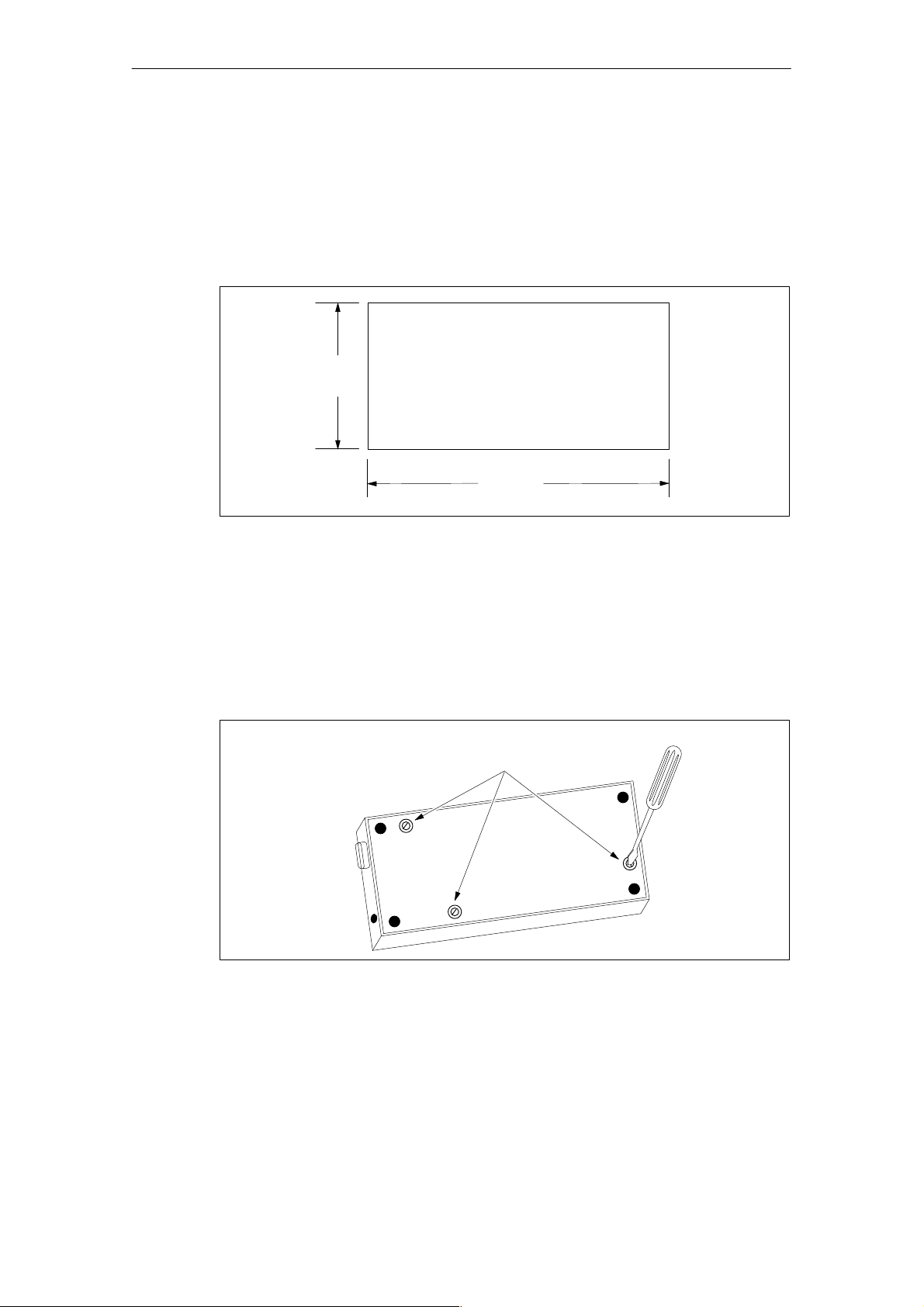
Use the template in Figure 1-2 to cut a 138 mm x 68 mm or 5.4 in. x 2.7 in. hole in the
mounting surface (DIN 43700).
68 mm
(2.7 in.)
138 mm
(5.4 in.)
Figure 1-2 Mounting Surface Hole Dimensions
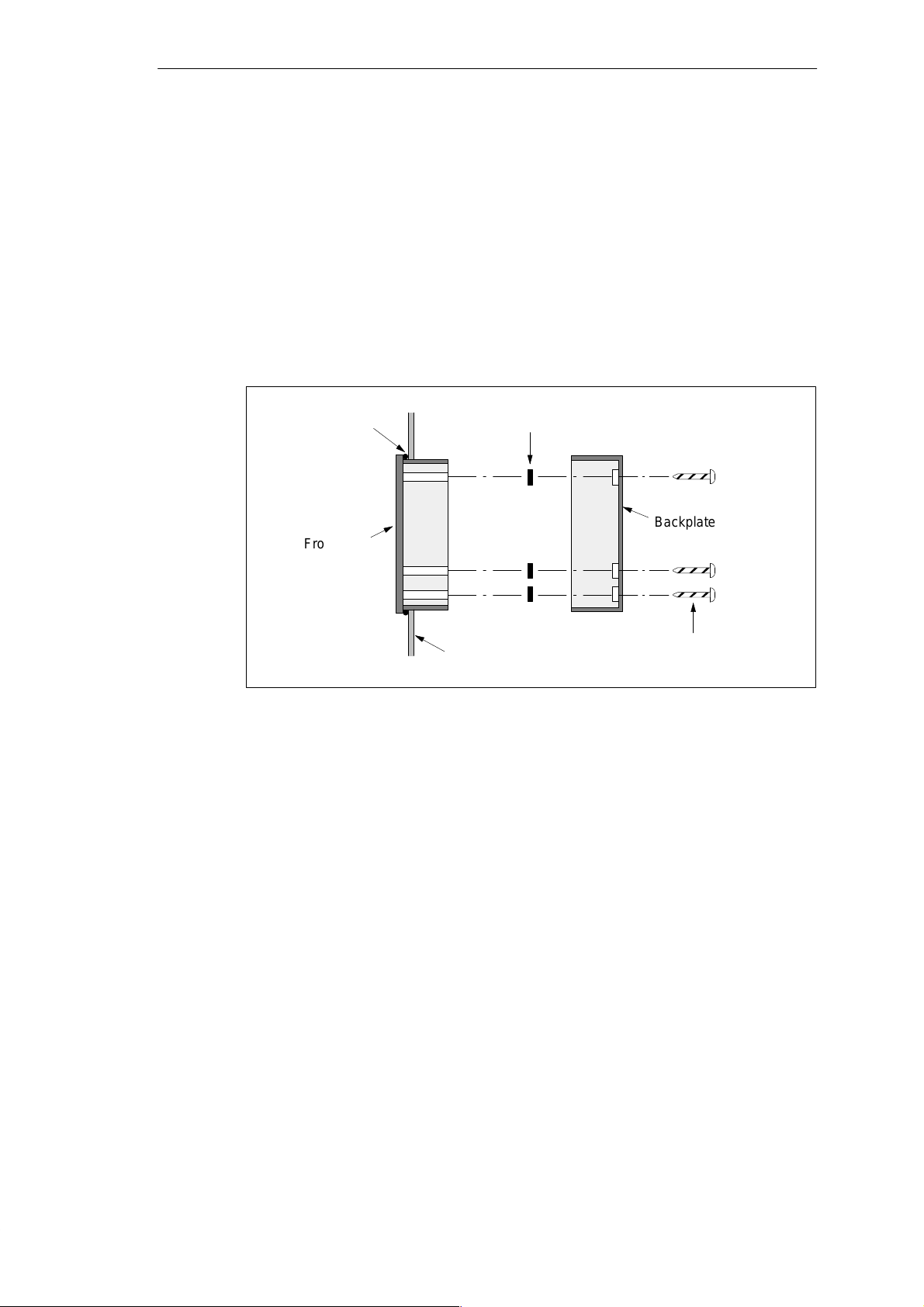
Preparing the TD 200 for Mounting
Use the following steps to prepare the TD 200 for mounting.
1. Remove the three screws from the rear of the TD 200 using a flat-head screwdriver. See
Figure 1-3.
2. Remove the backplate of the TD 200.
Figure 1-3 Removing the Three Mounting Screws
Mounting
Screws
1-4
SIMATIC TD 200 Operator Interface
C79000-G7076-C205-04
Product Overview and Installation
Self-adhesive spacers are included with the TD 200 for mounting the TD 200 to a mounting
surface. The number of spacers you require depends on the thickness of the mounting
surface. Use the following steps to install the spacers.
1. Use the following guidelines to determine the number of spacers required for proper
mounting.
– One spacer for door thickness from 0.3 mm to 1.5 mm (0.01 in. to 0.06 in.)
– Two spacers on top of each other for door thickness of 1.5 mm to 4.0 mm
(0.06 in. to 0.16 in.)
2. Place the spacers over the screw holes on the inside of the backplate. The spacers
maintain pressure on the TD 200 circuit board when the TD 200 is reassembled. See
Figure 1-4.
Figure 1-4 Positioning Spacers
Mounting the TD 200
Use the following steps and refer to Figure 1-4 to complete the mounting of your TD 200.
1. Place the supplied gasket on the frontplate of the TD 200.
2. Fit the frontplate into the cutout you made in the mounting surface.
3. Secure the backplate onto the frontplate of the TD 200 using the screws you removed
from the backplate. Tighten the screws.
Gasket
Frontplate
Spacers
Cabinet Door
or Control Panel
Backplate
Mounting
Screws
SIMATIC TD 200 Operator Interface
C79000-G7076-C205-04
1-5
Product Overview and Installation
1.3 Connecting the Communication Cable
The TD 200 communicates to the S7-200 CPU through the TD/CPU cable. You can
configure the TD 200 using the TD/CPU cable in the following ways:
S One-to-one configuration
S Multiple S7-200 CPU configuration
Installing Cable for One-to-One Communication
Use a one-to-one network configuration when you have just one S7-200 CPU to connect to
one TD 200. A one-to-one configuration consists of a TD 200, an S7-200 CPU, and a
TD/CPU cable that is supplied with the TD 200.
Figure 1-5 shows you a one-to-one configuration. The TD 200 communicates to and is
powered by the S7-200 CPU using the TD/CPU cable.
S7-200 CPU
TD 200
SIEMENS TD 200
Figure 1-5 One-to-One Configuration
Installing a Multiple CPU Network
Use a multiple CPU network configuration when you have several S7-200 CPUs to connect
to one or more TD 200s. For more information on configuring for multiple CPU
communication, refer to Appendix B.
Note
The TD 200 defaults to address 1 and attempts to communicate to a CPU at address 2.
See Section 3.8 to change the network address if other addresses are used.
TD/CPU Cable
SIMATIC
S7-200
1-6
SIMATIC TD 200 Operator Interface
C79000-G7076-C205-04
1.4 Connecting a Power Cable
The TD 200 receives power either from the S7-200 CPU or from an external plug-in power
supply unit.
Note
If you are using the TD 200 with a network of S7-200 CPUs, special consideration must be
taken with the communication and power connections. See Appendix B.
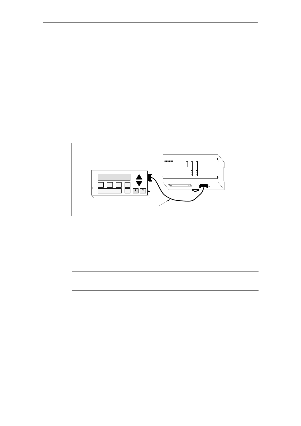
Supplying Power from the S7-200 CPU
Figure 1-6 shows you the TD 200 receiving its power from the CPU through the TD/CPU
cable. Use this type of power supply when the distance between the TD 200 and the S7-200
CPU is less than 2.5 m (8.2 ft.).
TD 200
SIEMENS
TD 200
Product Overview and Installation
S7-200 CPU
TD/CPU Cable
Figure 1-6 Supplying Power with the TD/CPU Cable
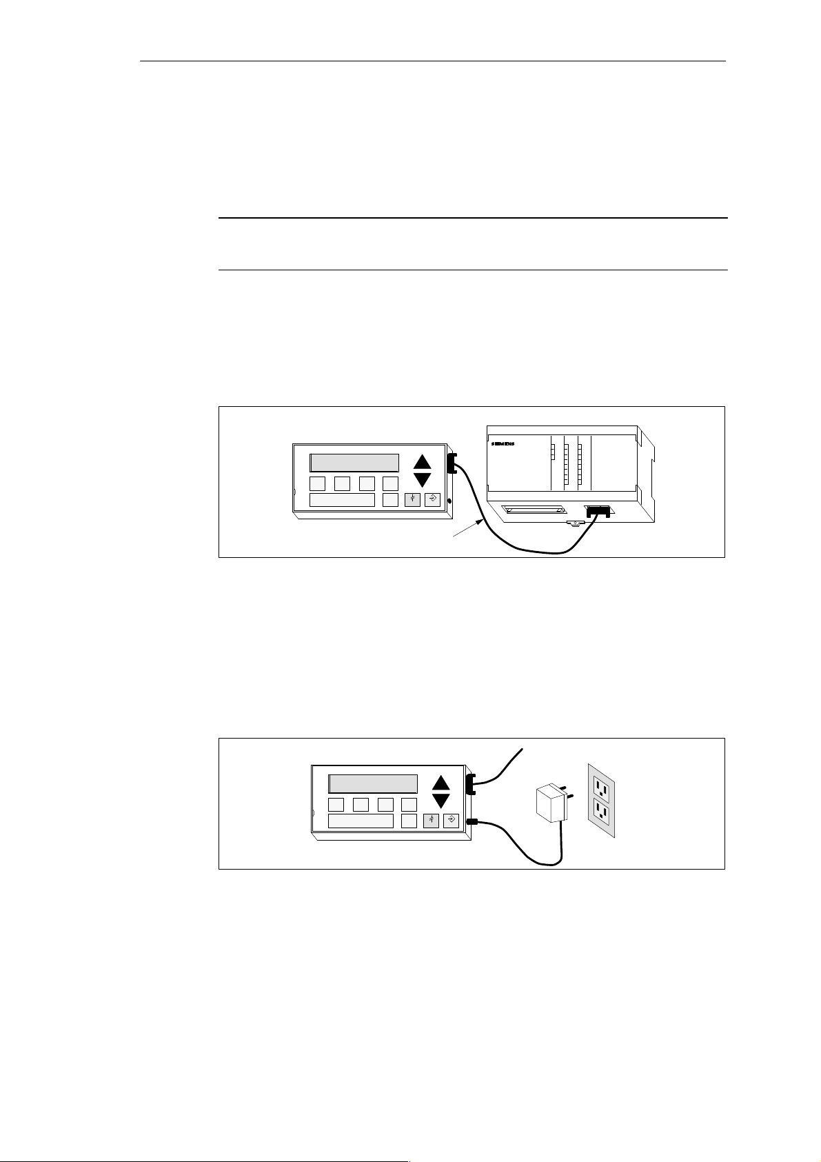
Supplying Power from an External Power Supply
Figure 1-7 shows the TD 200 receiving its power from an external power supply . Use this
type of power supply when the distance between the TD 200 and the S7-200 CPU is greater
than 2.5 m (8.2 ft.). If you choose to connect the TD 200 to the CPU with a longer cable
(2.5 m/8.2 ft.), use PROFIBUS components (see the SINEC IK10 Catalog). The power
supply is available from your Siemens distributor. See Appendix A for part numbers.
TD 200
SIEMENS
TD 200
SIMATIC
S7-200
To CPU
AC
Figure 1-7 Supplying Power Using an External Power Supply
SIMATIC TD 200 Operator Interface
C79000-G7076-C205-04
1-7

Product Overview and Installation
1-8
SIMATIC TD 200 Operator Interface
C79000-G7076-C205-04

Configuring the TD 200
The TD 200 is a text display device that displays messages enabled by the S7-200 CPU.
You do not have to configure or program the TD 200. The only operating parameters stored
in the TD 200 are the address of the TD 200, the address of the CPU, the baud rate, and the
location of the parameter block. The configuration of the TD 200 is stored in a TD 200
parameter block located in the variable memory (V memory) of the CPU. The operating
parameters of the TD 200, such as language, update rate, messages, and message-enabled
bits, are stored in the TD 200 parameter block in the CPU.
Upon power-up, the TD 200 reads the parameter block from the CPU. All of the parameters
are checked for legal values. If everything is acceptable, the TD 200 starts actively polling
the message-enabled bits to determine what message to display , reads the message from
the CPU, and then displays the message.
Chapter Overview
2
Section
2.1 Starting the STEP 7–Micro/WIN TD 200 Configuration Wizard 2-2
2.2 Creating a Sample Program 2-18
Description Page
SIMATIC TD 200 Operator Interface
C79000-G7076-C205-04
2-1
Configuring the TD 200
2.1 Starting the STEP 7–Micro/WIN TD 200 Configuration Wizard
STEP 7–Micro/WIN provides a “wizard” that makes it easy to configure the parameter block
and the messages in the data memory area of the S7-200 CPU. The TD 200 Configuration
Wizard automatically writes the parameter block and message texts to the data block editor
after you finish choosing the options and creating the messages. This data block can then be
downloaded to the CPU. For detailed information about the TD 200 parameter block and
message formats, see Appendix D.
This chapter contains the procedure for creating a sample TD 200 application. Use the
instructions in this example to create a TD 200 parameter block and three messages using
the TD 200 Configuration Wizard. The first message is text only . The second message
contains both text and embedded data. The third message is a text message that requires
acknowledgement by the operator.
The example also shows how to use the function keys to enable a message and how to use
the acknowledge- and edit-notification bits within your program.
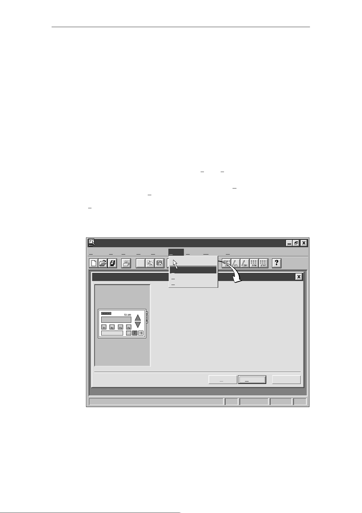
To open the wizard, select the menu command T
Figure 2-1.
To navigate through the dialog boxes of the wizard, click on “N
procedure, click on the “<P
rev” button to go back to a previous dialog box if you need to
change or review any of the parameters you have defined. In the final dialog box, click on
inish” to validate and save the parameter block and close the wizard.
“F
You can view the configured parameter block and messages by opening the
STEP 7–Micro/WIN data block editor.
ools " TD 200 Wizard... as shown in
ext>.” At any time during the
STEP 7-Micro/WIN – c:\microwin\project1.prj
Project Edit View CPU Debug Tools Setup Window Help
✂
TD 200 Configuration Wizard
Tools
Instruction Wizard..
D 200 Wizard...
T
roject Services ...
P
dit/Add Tools...
E
This wizard will help you configure TD 200 messages quickly and
easily. When you are finished, the wizard will generate the supporting
data block code for you.
To begin configuring TD 200 messages, click Next.
< Prev
Figure 2-1 Accessing the TD 200 Configuration Wizard
CancelNext >
1, 1
2-2
SIMATIC TD 200 Operator Interface
C79000-G7076-C205-04
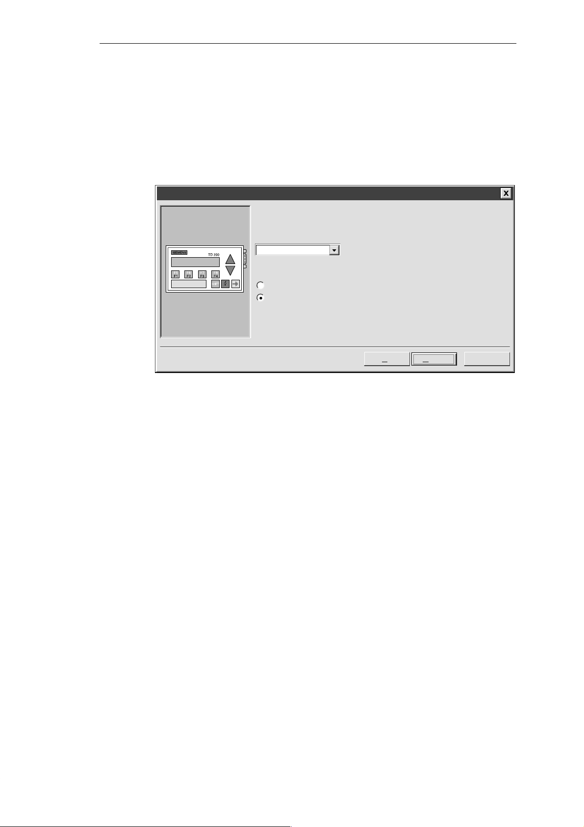
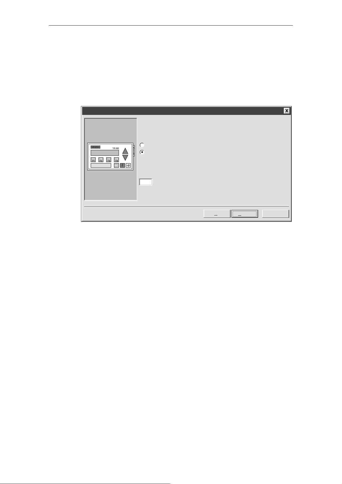
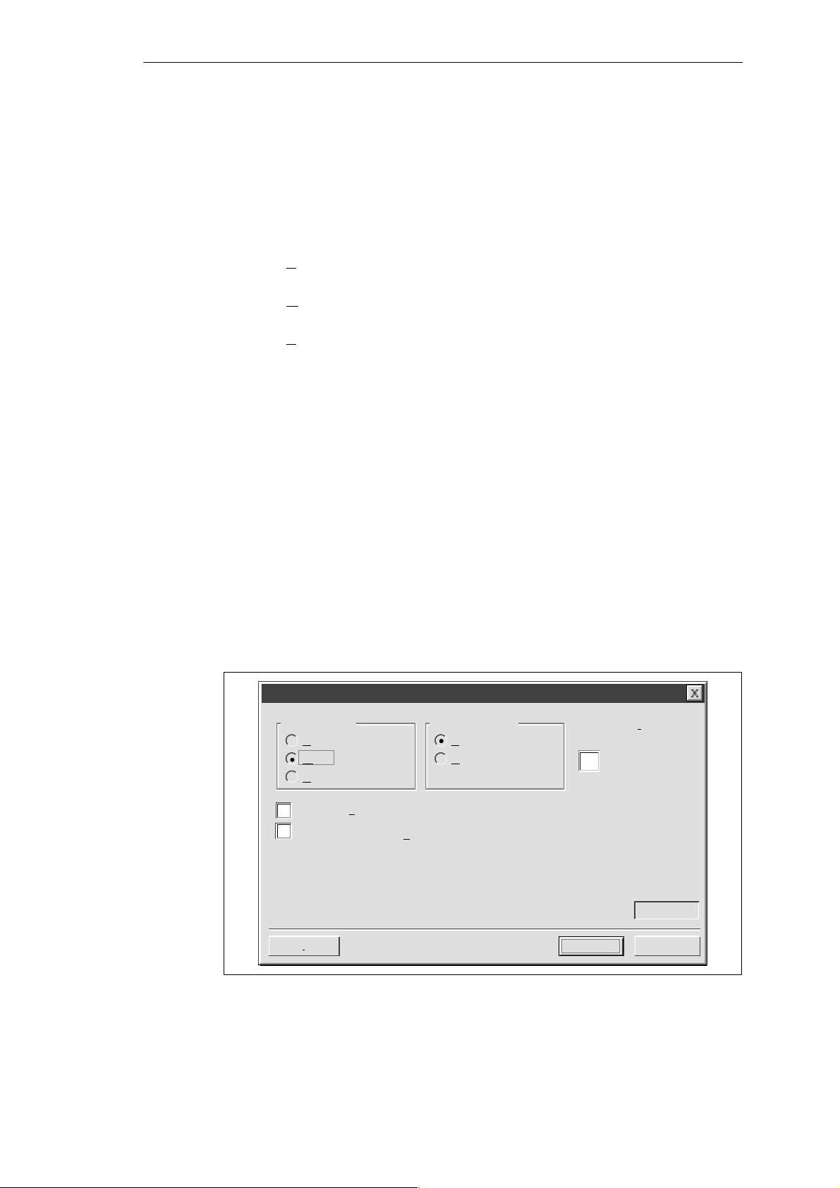
Selecting Language and Bar Graph Character Set
The first dialog box in the TD 200 Configuration Wizard allows you to select the language
and character set. Use the drop-down list box shown in Figure 2-2 to select the language in
which the TD 200 menus display . (This selection does not affect the text of the user
messages displayed on the TD 200.) Use the option buttons to select the standard
character set or the alternate character set. The alternate character set allows you to display
bar graph charts on the TD 200.
TD 200 Configuration Wizard
Y ou can configure the TD 200 to display menus and prompts in a specific
national language.
Which national language would you like your TD 200 to support?
English
Would you like to enable the Bar Graph character set?
Yes
No
Configuring the TD 200
Figure 2-2 Wizard: Language and Character Set
< Prev
Next >
Cancel
SIMATIC TD 200 Operator Interface
C79000-G7076-C205-04
2-3
Configuring the TD 200
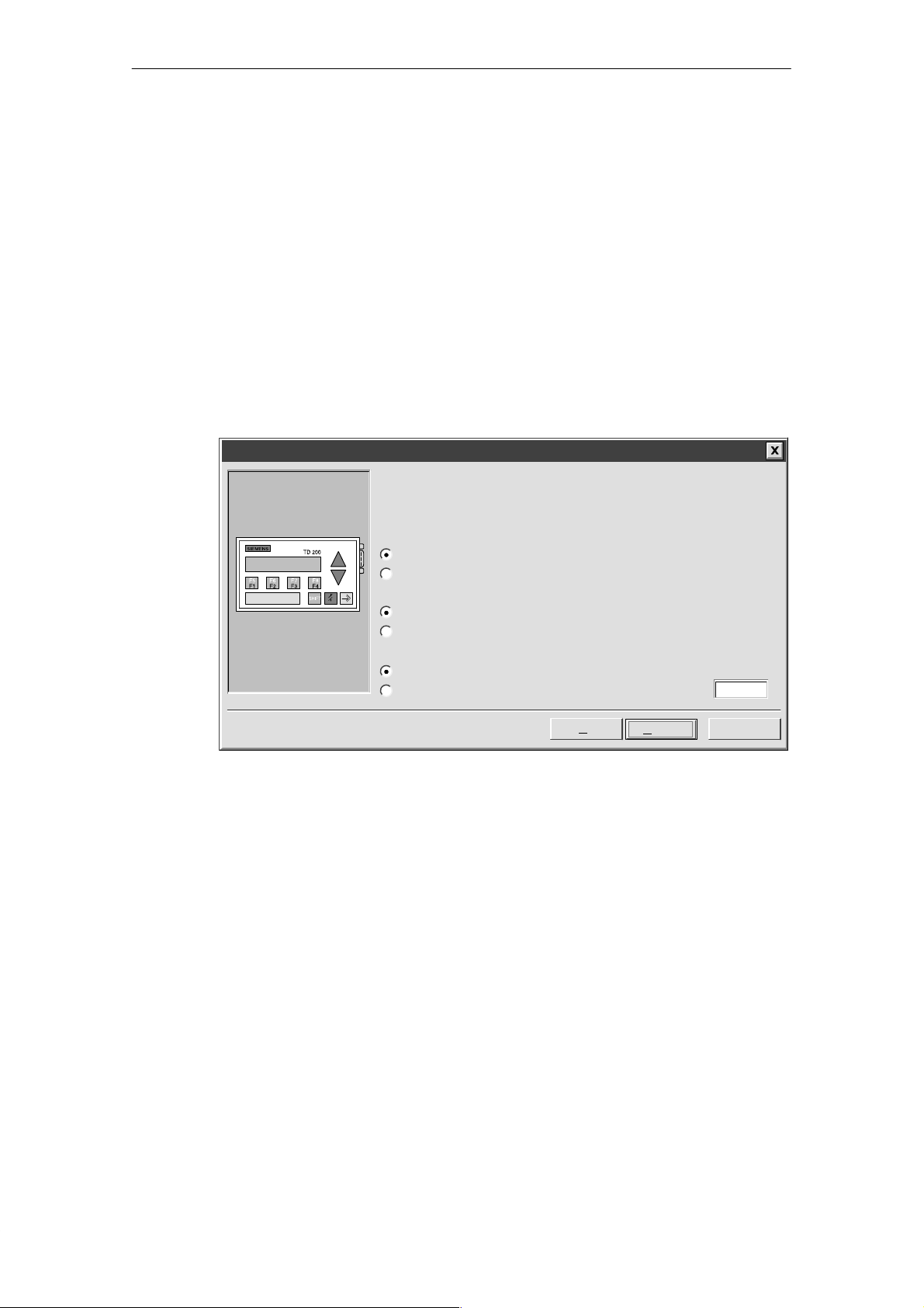
Enabling Time-of-Day, Force Function, and Password Protection
The dialog box shown in Figure 2-3 allows you to enable Menu mode options and set an edit
password.
The Time-of-Day (TOD) and force menu selections allow you to selectively enable the T OD
Clock menu and/or the Force menu. Once a selection is enabled, you are allowed to access
that menu in the TD 200. If the menu is not enabled, it does not appear in the TD 200 Menu
mode.
The password protection selection allows you to enable a four-digit password (from 0000 to
9999). The password controls the ability of the operator to edit variables embedded in a
message and to access the Menu mode. If you enable password protection, a field appears
in the dialog box for you to set the password. This password is not the CPU password and it
is stored in the TD 200 parameter block.
For this example, use the option buttons to select the modes shown in Figure 2-3. Set 1 111
as your password.
TD 200 Configuration Wizard
You can configure your TD 200 to allow the user to set the Time of Day clock in the
CPU, and to Force I/O in the CPU. You can also password-protect these options, so
that a user may only access them after entering the correct 4-digit password.
Would you like to enable the Time-of-Day (TOD) menu on your TD 200?
Yes
No
Would you like to enable the force menu on your TD 200?
Yes
No
Would you like to enable password protection?
Yes
No
Figure 2-3 Wizard: Time-of-Day Clock, Force I/O, and Password Protection
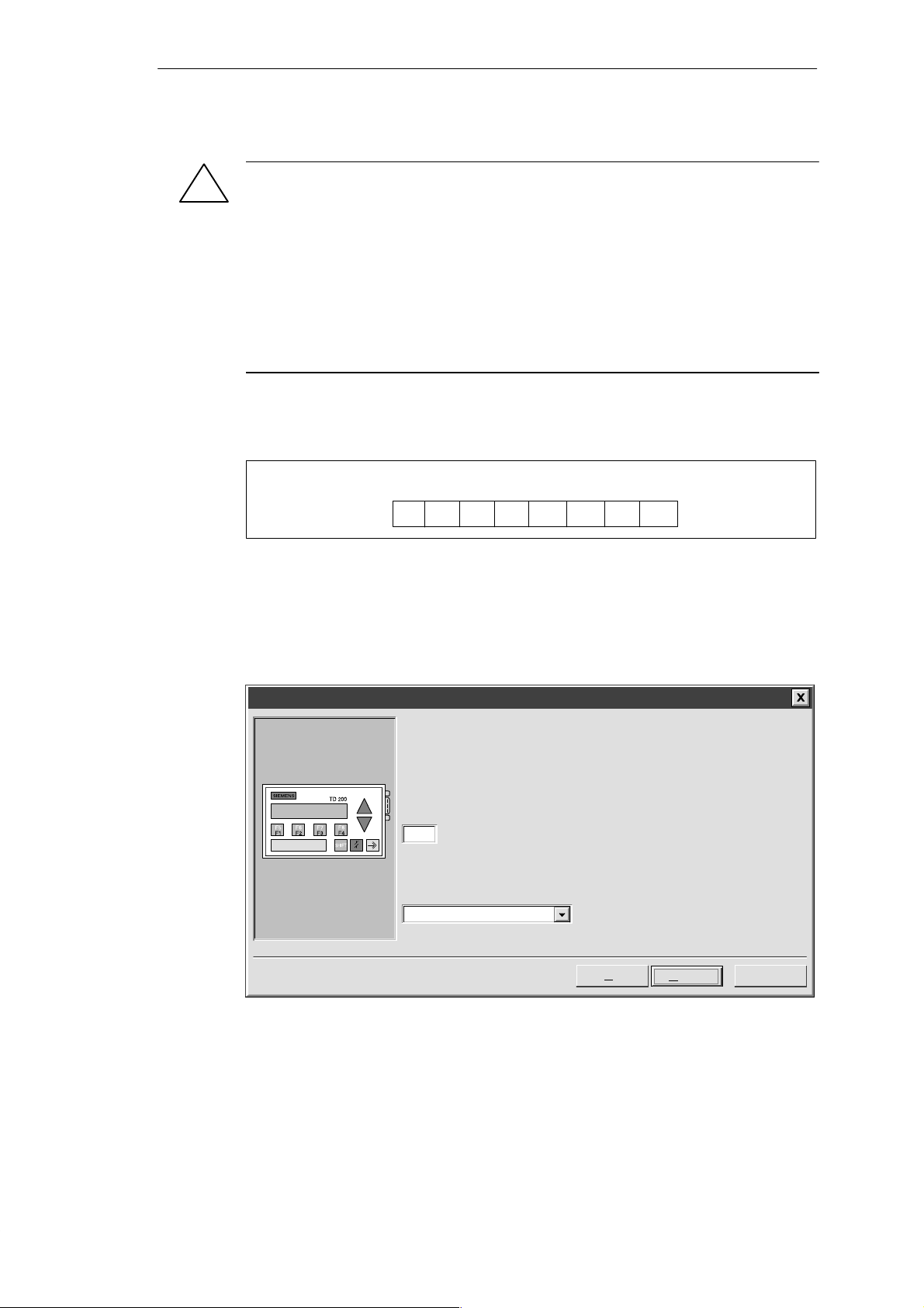
Specifying Function Key Memory Bits and Display Update Rate
The dialog box shown in Figure 2-5 allows you to specify the marker byte (M memory)
address for the TD 200 function keys and determine the update rate of the TD 200.
You must reserve eight bits of marker memory (M bits) for the TD 200 to use when a function
key is pressed. Your program can inspect these bits and take an action when a key is
pressed. One M bit is set by the TD 200 each time the corresponding function key is
pressed. Always reserve an M Area address even when your program does not utilize
function keys. Valid address values for specific CPUs are defined in the
Programmable Controller System Manual
.
< Prev
Next >
SIMA TIC S7-200
1111Password (0000 – 9999):
Cancel
2-4
SIMATIC TD 200 Operator Interface
C79000-G7076-C205-04
Configuring the TD 200
Warning
!
The TD 200 sets an M bit each time a function key is pressed. If you do not intend to use
function keys, and so do not assign an M byte address for function keys, the TD 200
defaults to byte M0 for the function keys. If your program uses bits in M0, and a user
presses any function key, the TD 200 sets the corresponding bit in M0, overwriting the
value assigned to that bit by your program.
Inadvertent changes to M bits could cause your program to behave unexpectedly .
Unpredictable controller operation could cause death or serious injury to personnel, and/or
damage to equipment.
Always reserve an M area address, even when your program does not utilize function
keys.
Figure 2-4 shows a referenced byte (MBn) and shows which bit of the byte is set by each
function key.
MSB
7
ShiftF4ShiftF3ShiftF2Shift
MBn
6543 21
F4 F3 F2 F1
F1
LSB
0
Figure 2-4 Bits Set by Each Function Key
The update rate selection determines how often the TD 200 polls the S7-200 CPU for
messages to display . The actual update time may be slower than the time that you select
because of the size of the message, the processing required, or network traffic.
For this example, select M0 and As fast as possible as shown in Figure 2-5.
TD 200 Configuration Wizard
The TD 200 has 8 function keys (F1 through F4 and SHIFT F1 through SHIFT F4)
that are used to set memory bits in the CPU. You must reserve eight bits of memory
(M bits) for the TD 200 to set when a function key is pressed. One M bit is set by
the TD 200 each time the corresponding function key is pressed.
Which byte of M memory would you like to reserve for the TD 200?
0
The update rate determines how often the TD 200 polls the CPU for messages to
display. How often would you like the TD 200 to poll for messages?
As fast as possible
Figure 2-5 Wizard: Function Key Memory Bits and Update Rate
SIMATIC TD 200 Operator Interface
C79000-G7076-C205-04
< Prev
Next >
Cancel
2-5
Configuring the TD 200
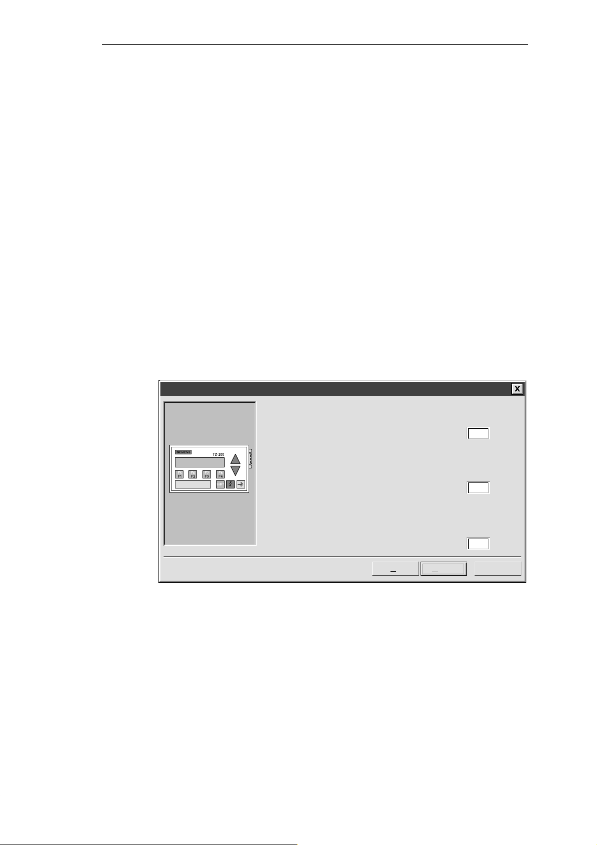
Selecting Message Size and Number of Messages
The dialog box shown in Figure 2-6 allows you to set the message size and quantity of
messages. Select a 20- or 40-character size for your messages. The TD 200 supports up to
80 messages. Enter a number from 1 to 80 in the text field to specify the number of
messages you want to create.
For this example, choose three 40-character messages.
TD 200 Configuration Wizard
The TD 200 allows two message sizes, please select the message size
you wish to support.
20 character message mode – displays two messages at a time
40 character message mode – displays one message at a time
The TD 200 allows you to configure up to 80 messages. How many
messages do you wish to configure?
3
Figure 2-6 Wizard: Message Size and Number of Messages
< Prev
Next >
Cancel
2-6
SIMATIC TD 200 Operator Interface
C79000-G7076-C205-04
Configuring the TD 200
Specifying Parameter Block Address, Message Enable Address, and Message Location
The dialog box shown in Figure 2-7 allows you to specify starting addresses for the
parameter block, the message enable flags, and the messages.
The TD 200 looks for a parameter block in the V memory of the CPU. The default location for
the parameter block is VB0. The default location can be changed. See Section 3.8 and
Section D.1 for information about placing the parameter block at other locations.
The starting byte for the message enable flags defines the location in V memory at which the
message enable flags begin. There are eight message enable flags stored in each byte.
Whole bytes must be allocated for message enable flags even if all the bits are not used.
The text in the dialog box shown in Figure 2-7 specifies how many bytes of V memory are
needed for message enable flags based on the number of messages you set in the previous
(Figure 2-6) dialog box.
The starting byte for message information defines the starting location of the first message in
V memory . Messages are placed consecutively in memory. Either 20 or 40 bytes are
reserved for each message based on your selection in the previous dialog box (Figure 2-6).
The text in the dialog box shown in Figure 2-7 specifies how many bytes are required for
messages.
V alues for the parameter block, enable flags, and message information starting addresses
are CPU specific. See the
valid address ranges for specific CPUs.
For this example, set the parameter block starting byte to 0, the enable flags address to 12,
and the message information starting address to 40 as shown in Figure 2-7.
SIMA TIC S7-200 Programmable Controller System Manual
for the
TD 200 Configuration Wizard
Y ou must now define where you would like the 12 byte parameter definition
to reside in your data block. It is usually located at VB0.
Y ou have defined 3 messages requiring 1 consecutive bytes for message
enable flags. Y ou must now define where you would like the enable flags to
reside in your data block.
Y ou have defined 3 messages requiring 120 consecutive bytes for the
message information. You must now define where you would like the
message information to reside in your data block.
< Prev
Figure 2-7 Wizard: Block Address, Enable Flags, and Message Location
Next >
0Starting byte for 12 byte parameter block:
12Starting byte for enable flags:
40Starting byte for message information:
Cancel
SIMATIC TD 200 Operator Interface
C79000-G7076-C205-04
2-7
Configuring the TD 200
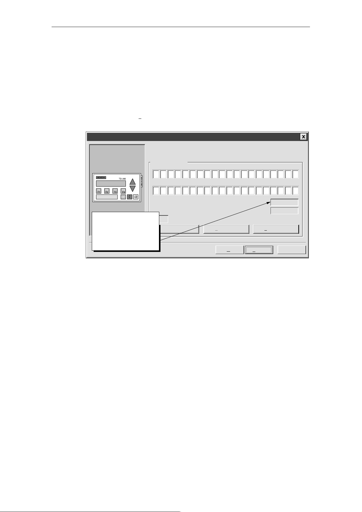
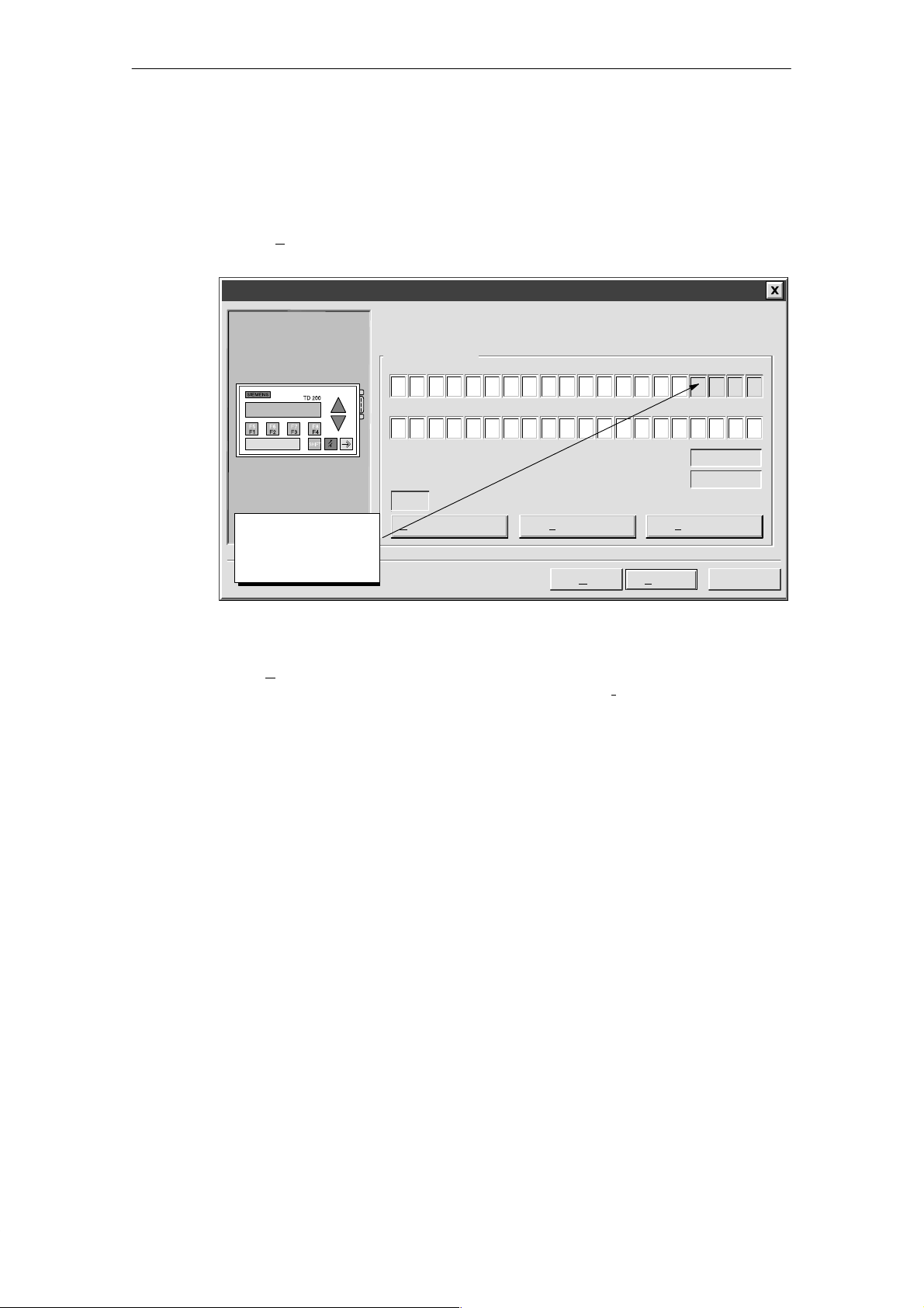
Creating A Text-Only Message
The dialog box in Figure 2-8 allows you to enter the text for a TD 200 message. The dialog
box also shows you the starting address of the message (Message beginning address). It
also shows you the address of the message-enabled bit for this message. Your program
uses this message-enabled bit to control the display of this message on the TD 200. Setting
the message-enabled bit to a 1 causes the TD 200 to read and display this message.
For this example, type in your message as shown in Figure 2-8. This is a text-only message,
so there is no embedded data. Since there are two more messages to configure in this
example, click on “Nex
TD 200 Configuration Wizard
t Message >” to continue.
You have asked to configure 3 message(s). Define your message by
placing your highest priority message first.
Message 1 of 3
PRESS F1 TO DISPLAY
THE NEXT MESSAGE . . .
5
25
10 15 20
30 35 40
Note: This field shows the
address of the particular
message. VB40 is the
address of MSG1, VB80
would be displayed for
MSG2, and so on.
INS
Embedded Data...
Figure 2-8 Wizard: 40-Character Message
Message beginning address:
Message enabled bit:
<Previous Message Next Message >
< Prev
Finish
VB40
V12.7
Cancel
2-8
SIMATIC TD 200 Operator Interface
C79000-G7076-C205-04

Embedding Data Values in a Text Message
You can place a data value within the message that displays on the TD 200. In order to
display a data value, you must reserve space in the message for the data value and for
format information. The format information tells the TD 200 how to display and edit the data
value. The format information requires the space of two characters in your message. Word
data values require the space of two characters in addition to the format information (four
characters total). Double word or real (floating point) values require the space of four
characters in addition to the format information (six characters total).
When you insert a data value into a message, you must be sure there are enough characters
to contain the format information and the embedded data value on the current line of the
display . For example, if you insert a word value, (two characters for the word value and two
characters for the format information), you must allow at least four spaces between the
starting position of the embedded data value and the end of the current message line.
The right-most character of an embedded data value serves as the anchor point for that
value in the TD 200 display . Data values are always right justified to that anchor point within
messages on the TD 200 display . As a data value grows in magnitude, it utilizes more
spaces to the left of the anchor point and can begin to use the spaces occupied by the
message text. Be sure to leave sufficient space between the end of your text and the anchor
point to allow for the expected range of the data value.
The number of display characters used to display a value varies with the size of the value.
This number of characters required to display a number is not the same as the number of
characters used to store the embedded data value in the message. The number of display
characters required depends on the range of values for that number in a specific application.
See Table D-1 for examples of the number of display characters required for different display
formats.
The TD 200 displays all values as decimal numbers. Positive signed values are displayed
without a sign. Negative signed values are displayed with a leading minus sign. Unsigned
values are displayed without a sign. A leading zero is used for all fractional numbers (for
example, 0.5). Real numbers are displayed with the number of decimal places you specify .
The value is rounded to the specified decimal place.
Configuring the TD 200
SIMATIC TD 200 Operator Interface
C79000-G7076-C205-04
2-9
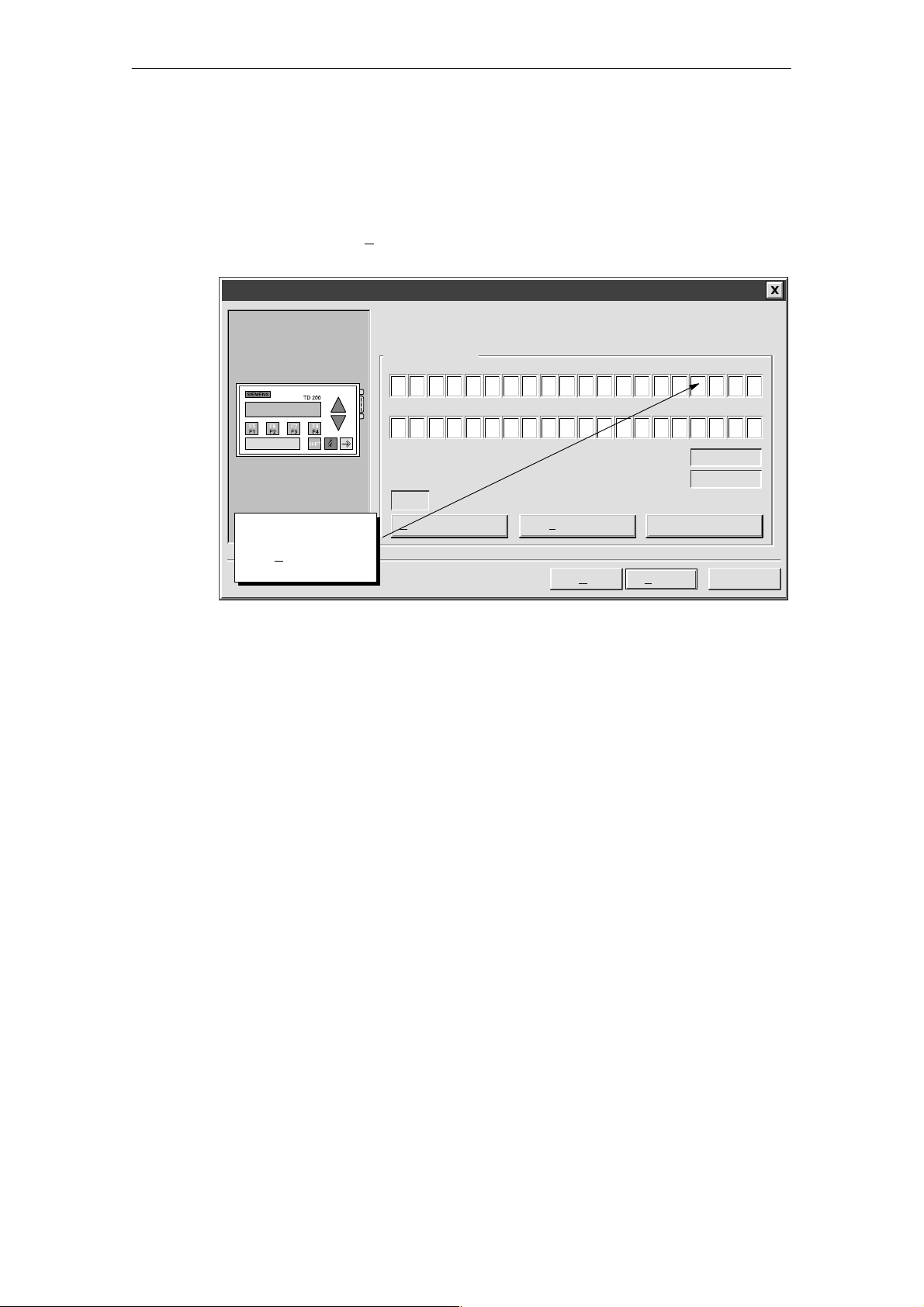
Configuring the TD 200
For this example, type in the text shown in Figure 2-9. This example message has two
embedded data values, one in the top line and one in the second line. The data value in the
top line is an integer. The data value in the second line is a real number.
A word value requires two characters for the value plus two more characters for format
information. Place the cursor at the character position shown in Figure 2-9 (four spaces from
the right). Click on the “E
TD 200 Configuration Wizard
mbedded Data...” button to bring up the Embedded Data dialog box.
You have asked to configure 3 message(s). Define your message by
placing your highest priority message first.
Message 2 of 3
PREV. SETPOINT :
NEW SETPOI NT :
5
25
10 15 20
30 35 40
Message beginning address:
Message enabled bit:
INS
Place cursor at the
correct position and
mbedded
click “E
Data...”
Embedded Data...
<Previous Message Next Message >
< Prev
Figure 2-9 Wizard: Embedding Variable Data Value in a Message
Finish
VB80
V12.6
Cancel
2-10
SIMATIC TD 200 Operator Interface
C79000-G7076-C205-04
Formatting the Embedded Data Value
Figure 2-10 shows the Embedded Data dialog box. This dialog box allows you to specify the
data type, format, and display characteristics of an embedded data value. You can also
select whether or not the message requires acknowledgement, whether the data value can
be edited, and whether or not editing requires a password. Some options depend on the
selections you make and do not appear when the dialog box opens.
The data format selection defines the size of the data value embedded in the message:
S Select “None” when a message requires acknowledgement but there is no embedded
data value to be displayed on the TD 200.
S Select “Word“ when the embedded data value is an integer. A word or integer value
requires the space of two characters within your message to hold the data value.
S Select “Double Word” when the embedded data value is a double word or a real (floating
point) value. A double word or real value requires the space of four characters within your
message to hold the data value.
The display format selection tells the TD 200 whether the data value is signed or unsigned.
The TD 200 uses this information when editing the data value. Signed values may be either
positive or negative numbers. Unsigned values are restricted to positive numbers.
The selection for digits to the right of the decimal provides scaling for the display of the data
value. If the data value is an integer, this selection allows you to scale the integer value for
display by specifying the location of the decimal point. For example, if the data value is equal
to 123 and you select 1 digit to the right of the decimal, the TD 200 displays 12.3.
The Embedded Data dialog box contains a check box to require acknowledgement of the
message. If a message requires acknowledgement, it flashes on the TD 200 display until the
operator presses ENTER. The dialog box also contains a check box for allowing editing of
the data value. If this box is selected, the operator can edit the embedded data value. If the
box is not checked, the data cannot be edited.
The Embedded Data dialog box also lists the address of the data value within the message.
The user program uses this address to write the data value in the message.
For this example, make the selections shown in Figure 2-10 and click “OK.”
Configuring the TD 200
Embedded Data
Data Format: Display Format:
None
W
Double Word
User must acknowledge message
Is the user allowed to e
Delete
Figure 2-10 TD 200 Message: Creating a Word Embedded Data
SIMATIC TD 200 Operator Interface
C79000-G7076-C205-04
ord
Signed
nsigned
U
dit this data?
Digits to the r
decimal
1
OK
ight of the
VW98Address of Data Value:
Cancel
2-11
Configuring the TD 200
Figure 2-1 1 shows the message dialog box after you have formatted the first embedded data
value. The grayed fields show the characters used by the format information (always two)
and the data value (two for word values).
The second data value in the message is a real number. Real numbers require four
characters plus two characters for format information. Move the cursor to position 35 and
click on “E
TD 200 Configuration Wizard
mbedded Data...” to enter the format information for the second data value.
You have asked to configure 3 message(s). Define your message by
placing your highest priority message first.
Message 2 of 3
PREV. SETPOINT :
NEW SETPOI NT :
5
25
10 15 20
30 35 40
Note: Grayed fields
are place holders for
embedded data
values.
INS
Embedded Data...
Message beginning address:
Message enabled bit:
<Previous Message Next Message >
< Prev
Finish
VB80
V12.6
Cancel
Figure 2-11 Wizard: Embedded Data Value Place Holder in Message
This variable displays as a real number which requires a double word data format. After you
select “D
number format. For real numbers, the field entitled Digits to the r
ouble Word,” the Display Format area allows selection of a real (floating point)
ight of the decimal defines
the fixed decimal location of the real number in the TD 200 display . The TD 200 rounds a real
number to the specified decimal place. For example, if the real number value is 123.456 and
you select 2 digits to the right of the decimal, the TD 200 displays this value as 123.46.
In this example, this variable should be editable by the user. Select the check box that allows
the user to edit the data. Once the edit-allowed selection has been made, two new fields
appear in the Embedded Data dialog box.
The Edit Notification Bit field specifies the location of a bit which the TD 200 sets to 1
whenever the data value is edited and written to the CPU. The CPU program uses the
edit-notification bit to recognize when an editable data value has been changed. The
program can then read and make use of the edited value. The user program is responsible
for resetting this bit to 0.
The password-protected check box asks you if you wish to require a password for editing
this data value. If checked, the operator must enter a password before being allowed to edit
the data value. You selected the password at the beginning of the configuration process (see
Figure 2-3); it is shown in the Password for Edit field.
2-12
SIMATIC TD 200 Operator Interface
C79000-G7076-C205-04
 Loading...