

Page 1

Preface, Contents
SIMATIC
SM 335 – High-Speed
Analog Input/Output Module for
the SIMATIC S7-300
Manual
Characteristics and Technical
Specifications of the SM 335
Connecting the Inputs and
Outputs of the SM 335
Data Exchange with the SM 335
Interval Counter Input
Special SM 335 Operating Modes
Detecting and Correcting Faults
List of Abbreviations
Index
1
2
3
4
5
6
A
08/2004 Edition
6ES7 335-7HG00-8BA1
Page 2

OChapter
Safety-Related Guidelines
This manual contains notices intended to ensure personal safety, as well as to protect the products and
connected equipment against damage. These notices are highlighted by a warning triangle and are graded
according to severity by the following texts:
Danger
!
Indicates that death, severe personal injury or substantial property damage will result if proper
precautions are not taken.
Warning
!
Indicates that death, severe personal injury or substantial property damage can result if proper
precautions are not taken.
Caution
!
Indicates that minor personal injury or property damage can result if proper precautions are not taken.
Caution
indicates that property damage can result if proper precautions are not taken.
Notice
contains important information about the product, its operation or a part of the document, to which special
attention is drawn.
Qualified Personnel
A device/system may only be commissioned or operated by qualified personnel. Qualified personnel as
referred to in the safety guidelines in this document are persons authorized to start up, ground and tag
circuits, equipment and systems in accordance with established safety practice.
Proper Usage
Please observe the following:
Warning
!
Registered Trademarks
The equipment/system or the system components may only be used for the applications described in the
catalog or the technical description, and only in combination with the equipment, components, and
devices of other manufacturers as far as this is recommended or permitted by Siemens.
The product will function correctly and safely only if it is transported, stored, set up, and installed as
intended, and operated and maintained with care.
SIMATIC, SIMATIC HMI and SIMATIC NET are registered trademarks of SIEMENS AG.
Other designations used in this document may be registered trademarks; the owner’s rights may be viola-
ted if they are used by third parties for their own purposes.
The reproduction, transmission or use of this document or its
contents is not permitted without express written authority.
Offenders will be liable for damages. All rights, including rights
created by patent grant or registration of a utility model or design, are
reserved.
Siemens AG
Automation & Drives
Motion Control Systems
P.O. Box 3180, D-91050 Erlangen
Index-2
Siemens Aktiengesellschaft
SM 335 – High-Speed Analog Input/Output Module for the SIMATIC S7-300
Exclusion of LiabilityCopyright W Siemens AG, 1999 – 2004. All rights reserved
We have checked the contents of this manual for agreement with the
hardware and software described. Since deviations cannot be
precluded entirely, we cannot guarantee full agreement. However,
the data in this manual are reviewed regularly and any necessary
corrections included in subsequent editions. Suggestions for
improvement are welcomed.
Siemens AG, 2004.
Technical data subject to change.
6ES7 335-7HG00-8BA1
Page 3

Preface
Important
In order to obtain SIMATIC interference immunity, the SM 335 module must
always be operated with an interference suppression filter (see Section 2.6).
Content of this manual
This manual describes the function of the SM 335 analog input/output module;
AI4/AO4 x 14/12 bits. In the following, this module will simply be called SM 335.
Aim of this manual
The information contained in this manual will enable you to:
• Use a SM 335 in a SIMATIC S7-300.
• See operator inputs, function descriptions and technical specifications in con-
nection with the SM 335.
Scope of this manual
The manual is valid for the following modules:
Module Order Number From Revision Level
SM 335 6ES7 335-7HG01-0AB0 02
This manual contains the descriptions of these modules that are valid at the time
the manual is released. For new modules and new versions of modules, we reserve the right to add to the manual a product information containing the current
information about this module. Section 1.2 describes how to determine the revision
level of a module.
SM 335 – High-Speed Analog Input/Output Module for the SIMATIC S7-300
6ES7 335-7HG00-8BA1
iii
Page 4

PrefacePreface
Scope of the documentation package
You can order the documentation for the SM 335 separately from the module.
The order number for the manual appears in the table below:
Documentation Order Number
• SM 335 - High-Speed Analog Input/Output
Module for the SIMATIC S7-300
Other references
More information about using and installing SIMATIC S7-300 analog modules can
be found in:
• SIMATIC Programmable Controller, S7-300 Module Data Reference Manual
• SIMATIC S7-300, Hardware and Installation Manual
6ES7 335-7HG00-8BA1
The installation guidelines described in this document also relate to the SM 335.
Required basic knowledge
This manual assumes general knowledge of automation engineering.
Knowledge of the SIMATIC S7 programmable controller and the STEP 7 Engineering System is also required.
Approbations
The S7-300 programmable controller has obtained the following approvals:
• Underwriters Laboratories, Inc.: UL 508 registered (Industrial Control Equip-
ment)
• Canadian Standards Association: CSA C22.2 number 142, (Process Con-
trol Equipment)
• Factory Mutual Research: Approval Standard Class Number 3611.
CE Approval
The S7-300 programmable controller meets the requirements and safety-related
requirements of the following EC directives:
• EC Directive 73/23/EEC “Low-Voltage Directive”
• EC Directive 89/336/EEC “EMC Directive”
iv
SM 335 – High-Speed Analog Input/Output Module for the SIMATIC S7-300
6ES7 335-7HG00-8BA1
Page 5

C-Tick-Mark
The S7-300 programmable controller meets the requirements of the AS/NZS 2064
standard (Australia and New Zealand).
Standards
The S7-300 programmable controller meets the requirements and criteria of the
IEC 61131-2 standard (Programmable Controllers, Part 2: Equipment Requirements and Tests).
How the manual fits in
PrefacePreface
Manual
• CPU 31xC and CPU 31x, Technical Specifi-
cations
Reference Manual
• CPU data: CPU 312 IFM - 318-2 DP
Manual
• S7-300, CPU 31xC and CPU 31x: Hard-
ware and Installation
Installation Manual
• S7-300 Programmable Controller: Hardware
and Installation: CPU 312 IFM - 318-2 DP
System Manual
• PROFINET system description
Programming Manual
• From PROFIBUS DP to PROFINET IO
Manual
• CPU 31xC: Technological Functions
• Examples
Reference Manual
• S7-300 Programmable Controller:Module
Data
Operation and display elements, communication, memory concept, cycle and
response times, technical specifications.
Operation and display elements, communication, memory concept, cycle and
response times, technical specifications.
Configuration, installation, wiring, addressing, commissioning, maintenance,
diagnostics, and interference suppression.
Configuration, installation, wiring, addressing, commissioning, maintenance,
diagnostics, and interference suppression.
Basic information about PROFINET:
Network components, data exchange
and communication, PROFINET IO,
component based automation, application example PROFINET IO and component based automation.
Guide to migration from PROFIBUS DP
to PROFINET IO.
Description of individual technological
functions: Positioning, counting,
point-to-point coupling, control.
The CD contains examples for the technological functions.
Descriptions of functions and technical
specifications of signal modules, power
supply modules and interface modules.
Instruction List
• CPU 312 IFM - 318-2 DP
• CPU 31xC and CPU 31x
SM 335 – High-Speed Analog Input/Output Module for the SIMATIC S7-300
6ES7 335-7HG00-8BA1
The instruction set lists of the CPUs and
their execution times;
A list of executable blocks.
v
Page 6

PrefacePreface
Getting Started
The Getting Started documents below are available as an anthology:
• CPU 31x: Commissioning
• CPU 31xC: Commissioning
• CPU 31xC: Positioning with analog output
• CPU 314C: Positioning with digital output
• CPU 31xC: Counting
• CPU 31xC: Rules
• CPU 31xC: Point-to-point connection
• CPU 31x-2 PN/DP: Commissioning of a
PROFINET IO subnet
Manual
You are reading manual
• SM 335 - High-Speed Analog Input/Output
Module for the SIMATIC S7-300
Reference Manual
System software for the S7-300/400 system
and standard functions
Manual
SIMATIC NET: Twisted Pair and Fiber Optic Networks
Manual
Component based Automation:
Configuring systems with SIMATIC iMap
Manual
Programming with STEP 7 V5.3
Manual
Communication with SIMATIC
Getting Started documents use a concrete example to guide you through the
individual commissioning steps until you
have a functioning application.
Description of how you use the SM 335
module in a SIMATIC S7-300.
Overview of operations, descriptions of
functions and technical specifications of
the SM 335.
Description of system functions (SFC),
system function blocks (SFB) and organization blocks (OB).
This manual is part of the STEP 7 documentation package.
The description can also be found in the
STEP 7 online help.
Description of industrial Ethernet networks, network configuration, components, installation guidelines for networked automation systems in buildings,
etc.
Description of SIMATIC iMAP configuration software.
Programming with STEP 7.
Fundamentals, services, networks, communication functions, connection of
PG/OP, configuration in STEP 7.
Additional Support
Please contact your local Siemens representative if you have any queries about
the product described in this manual, which are not answered here.
http://www.ad.siemens.com/automation/partner
vi
SM 335 – High-Speed Analog Input/Output Module for the SIMATIC S7-300
6ES7 335-7HG00-8BA1
Page 7

Training center
We offer a range of relevant courses to help you to get started with the
SIMATIC S7 programmable controller. Please contact your local training center or
the central training center in Nuremberg, D 90327 Germany.
Phone: +49 (911) 895-3200
Internet: http://www.sitrain.com
A&D Technical Support
Worldwide, available 24 hours a day:
Johnson City
PrefacePreface
Nuremberg
Beijing
Technical Support
Worldwide (Nuremberg)
Technical Support
Local time: 24 hours a day,
Phone: +49 (180) 5050-222
Fax: +49 (180) 5050-223
E-mail: adsupport@
GMT: +1:00
Europe/Africa (Nuremberg)
Authorization
Local time: Mon.-Fri. 8:00 AM
Phone: +49 (180) 5050-222
Fax: +49 (180) 5050-223
E-mail: adsupport@
GMT: +1:00
The languages of the technical support and authorization hotlines are generally German and English.
365 days a year
siemens.com
to 5:00 PM
siemens.com
United States (Johnson City)
Technical Support and
Authorization
Local time: Mon.-Fri. 8:00 AM
to 5:00 PM
Phone: +1 (423) 262 2522
Fax: +1 (423) 262 2289
E-mail: simatic.hotline@
sea.siemens.com
GMT: –5:00
Asia/Australia (Beijing)
Technical Support and
Authorization
Local time: Mon.-Fri. 8:30:00
to 5:00 PM
Phone: +86 10 64 75 75 75
Fax: +86 10 64 74 74 74
E-mail: adsupport.asia@
siemens.com
GMT: +8:00
SM 335 – High-Speed Analog Input/Output Module for the SIMATIC S7-300
6ES7 335-7HG00-8BA1
vii
Page 8

PrefacePreface
Service & Support on the Internet
In addition to our documentation, our whole range of expertise can be accessed
online at:
http://www.siemens.com/automation/service&support
Where you will find:
• The Newsletter, which constantly provides you with up-to-date information
about your products.
• The documents you need via our Search function in Service & Support.
• A forum, where users and experts from all over the world exchange their experi-
ences.
• Your local representative for Automation & Drives, via our database of repre-
sentatives.
• Information about field service, repairs and spare parts. Much more can be
found under “Services”.
Queries
If you have any queries about the S7-300 programmable controller, please contact
your local Siemens representative.
In case you have any questions or suggestions concerning this manual, please fill
in the correction sheet and return it to us. The correction sheet can be found at the
end of the manual.
viii
SM 335 – High-Speed Analog Input/Output Module for the SIMATIC S7-300
6ES7 335-7HG00-8BA1
Page 9

Contents
1 Characteristics and Technical Specifications of the SM 335 1-1. . . . . . . . . . . . . . . .
1.1 Characteristics features of the SM 335 1-2. . . . . . . . . . . . . . . . . . . . . . . . . . . . .
1.2 Terminal connection diagram for the SM 335 1-3. . . . . . . . . . . . . . . . . . . . . . . .
1.3 Block diagram of the SM 335 1-5. . . . . . . . . . . . . . . . . . . . . . . . . . . . . . . . . . . . .
1.4 Setting the measuring range with the measuring range module 1-6. . . . . . . .
1.5 Technical specifications for the SM 335 1-7. . . . . . . . . . . . . . . . . . . . . . . . . . . . .
1.5.1 General technical specifications 1-7. . . . . . . . . . . . . . . . . . . . . . . . . . . . . . . . . . .
1.5.2 Technical specifications for the analog inputs 1-8. . . . . . . . . . . . . . . . . . . . . . . .
1.5.3 Technical specifications for the analog outputs 1-10. . . . . . . . . . . . . . . . . . . . . .
1.5.4 Technical specifications for the interval counter 1-11. . . . . . . . . . . . . . . . . . . . . .
1.6 SM 335 operating modes 1-13. . . . . . . . . . . . . . . . . . . . . . . . . . . . . . . . . . . . . . . . .
1.6.1 Free Cycle mode 1-13. . . . . . . . . . . . . . . . . . . . . . . . . . . . . . . . . . . . . . . . . . . . . . . .
1.6.2 Conditional Cycle mode 1-16. . . . . . . . . . . . . . . . . . . . . . . . . . . . . . . . . . . . . . . . . .
2 Connecting the Inputs and Outputs of the SM 335 2-1. . . . . . . . . . . . . . . . . . . . . . . .
2.1 Basic information about connecting the SM 335 2-2. . . . . . . . . . . . . . . . . . . . .
2.2 Connecting the analog inputs 2-3. . . . . . . . . . . . . . . . . . . . . . . . . . . . . . . . . . . . .
2.3 Connecting the analog outputs 2-5. . . . . . . . . . . . . . . . . . . . . . . . . . . . . . . . . . . .
2.4 Connecting the interval counter input 2-6. . . . . . . . . . . . . . . . . . . . . . . . . . . . . . .
2.5 Connecting the sensor power supply 2-7. . . . . . . . . . . . . . . . . . . . . . . . . . . . . . .
2.5.1 Correcting the sensor power supply 2-9. . . . . . . . . . . . . . . . . . . . . . . . . . . . . . . .
2.6 Interference suppression filter for 24 V supply voltage 2-10. . . . . . . . . . . . . . . .
3 Data Exchange with the SM 335 3-1. . . . . . . . . . . . . . . . . . . . . . . . . . . . . . . . . . . . . . . . .
3.1 Access via the I/O addresses 3-3. . . . . . . . . . . . . . . . . . . . . . . . . . . . . . . . . . . . .
3.1.1 Output values 3-3. . . . . . . . . . . . . . . . . . . . . . . . . . . . . . . . . . . . . . . . . . . . . . . . . . .
3.1.2 Output values 3-7. . . . . . . . . . . . . . . . . . . . . . . . . . . . . . . . . . . . . . . . . . . . . . . . . . .
3.1.3 Analog value representation for analog input channels 3-8. . . . . . . . . . . . . . . .
3.1.4 Analog value representation for analog output channels 3-10. . . . . . . . . . . . . .
3.2 Setting parameters via HW Config 3-11. . . . . . . . . . . . . . . . . . . . . . . . . . . . . . . . .
3.2.1 SM 335 default settings 3-12. . . . . . . . . . . . . . . . . . . . . . . . . . . . . . . . . . . . . . . . . .
3.2.2 SM 335 parameters assignable with HW Config 3-13. . . . . . . . . . . . . . . . . . . . .
3.3 Modifying SM 335 parameters with the help of system function 55 3-16. . . . .
3.3.1 SM 335 static parameters 3-17. . . . . . . . . . . . . . . . . . . . . . . . . . . . . . . . . . . . . . . .
3.3.2 SM 335 parameters in the Free Cycle and Conditional Cycle Modes 3-18. . . .
3.3.3 SM 335 parameter for “Comparator” mode 3-23. . . . . . . . . . . . . . . . . . . . . . . . . .
3.3.4 SM 335 parameters for “Measuring Only” special mode 3-27. . . . . . . . . . . . . . .
SM 335 – High-Speed Analog Input/Output Module for the SIMATIC S7-300
6ES7 335-7HG00-8BA1
ix
Page 10

ContentsContents
3.4 Evaluating SM 335 diagnostics 3-29. . . . . . . . . . . . . . . . . . . . . . . . . . . . . . . . . . . .
3.4.1 Hardware interrupt 3-30. . . . . . . . . . . . . . . . . . . . . . . . . . . . . . . . . . . . . . . . . . . . . . .
3.4.2 Format of diagnostic data for the SM 335 3-32. . . . . . . . . . . . . . . . . . . . . . . . . . .
3.4.3 Module diagnostic byte 1 (byte 0) 3-33. . . . . . . . . . . . . . . . . . . . . . . . . . . . . . . . . .
3.4.4 Module diagnostic byte 2 (byte 1) 3-35. . . . . . . . . . . . . . . . . . . . . . . . . . . . . . . . . .
3.4.5 Module diagnostic byte 3 (byte 2) 3-35. . . . . . . . . . . . . . . . . . . . . . . . . . . . . . . . . .
3.4.6 Module diagnostic byte 4 (byte 3) 3-36. . . . . . . . . . . . . . . . . . . . . . . . . . . . . . . . . .
3.4.7 Channel-specific diagnostic bytes (bytes 4-15) 3-37. . . . . . . . . . . . . . . . . . . . . .
4 Interval Counter Input 4-1. . . . . . . . . . . . . . . . . . . . . . . . . . . . . . . . . . . . . . . . . . . . . . . . . . .
4.1 Principle of an interval counter 4-2. . . . . . . . . . . . . . . . . . . . . . . . . . . . . . . . . . . .
4.2 Principles of measuring with the interval counter 4-3. . . . . . . . . . . . . . . . . . . . .
4.3 Wiring the interval counter input 4-5. . . . . . . . . . . . . . . . . . . . . . . . . . . . . . . . . . .
4.4 Initializing the SM 335’s interval counter input 4-7. . . . . . . . . . . . . . . . . . . . . . .
4.5 Interval counter values 4-8. . . . . . . . . . . . . . . . . . . . . . . . . . . . . . . . . . . . . . . . . . .
4.6 Example for determining the speed by means of the interval counter 4-9. . .
5 Special SM 335 Operating Modes 5-1. . . . . . . . . . . . . . . . . . . . . . . . . . . . . . . . . . . . . . . .
5.1 Switching to the special operating modes 5-2. . . . . . . . . . . . . . . . . . . . . . . . . . .
5.2 “Comparator” mode 5-3. . . . . . . . . . . . . . . . . . . . . . . . . . . . . . . . . . . . . . . . . . . . . .
5.2.1 How comparator mode works 5-4. . . . . . . . . . . . . . . . . . . . . . . . . . . . . . . . . . . . .
5.2.2 SM 335 parameters for Comparator mode 5-10. . . . . . . . . . . . . . . . . . . . . . . . . .
5.3 “Measuring Only” mode 5-14. . . . . . . . . . . . . . . . . . . . . . . . . . . . . . . . . . . . . . . . . .
5.3.1 Switching to “Measuring Only” mode 5-15. . . . . . . . . . . . . . . . . . . . . . . . . . . . . . .
6 Detecting and Correcting Faults 6-1. . . . . . . . . . . . . . . . . . . . . . . . . . . . . . . . . . . . . . . . .
6.1 Principle of diagnostics 6-2. . . . . . . . . . . . . . . . . . . . . . . . . . . . . . . . . . . . . . . . . . .
6.2 Configuring diagnostics with HW Config 6-4. . . . . . . . . . . . . . . . . . . . . . . . . . . .
6.3 Evaluating diagnostic data in OB 82 6-6. . . . . . . . . . . . . . . . . . . . . . . . . . . . . . .
6.4 SM 335 error tree 6-7. . . . . . . . . . . . . . . . . . . . . . . . . . . . . . . . . . . . . . . . . . . . . . .
6.5 Troubleshooting 6-8. . . . . . . . . . . . . . . . . . . . . . . . . . . . . . . . . . . . . . . . . . . . . . . . .
A List of Abbreviations A-1. . . . . . . . . . . . . . . . . . . . . . . . . . . . . . . . . . . . . . . . . . . . . . . . . . .
Index Index-1. . . . . . . . . . . . . . . . . . . . . . . . . . . . . . . . . . . . . . . . . . . . . . . . . . . . . . . . . . . . .
x
SM 335 – High-Speed Analog Input/Output Module for the SIMATIC S7-300
6ES7 335-7HG00-8BA1
Page 11

Characteristics and Technical Specifications of the SM 335
SIMATIC S7-300
The SM 335 is an input/output module (signal module) for the SIMATIC S7-300.
The SM 335 has the same general technical specifications as all signal modules of
the SIMATIC S7-300.
Order number
Order the SM 335 under the following order number:
6ES7 335-7HG01-0AB0
In this chapter
We deal with the following topics in this chapter:
Topic Section
Characteristics of the SM 335 1.1
1
Terminal connection diagram for the SM 335 1.2
Block diagram of the SM 335 1.3
Setting the measuring range with the measuring range module 1.4
Technical specifications for the SM 335 1.5
Operating modes of the SM 335 1.6
SM 335 – High-Speed Analog Input/Output Module for the SIMATIC S7-300
6ES7 335-7HG00-8BA1
1-1
Page 12

Characteristics and Technical Specifications of the SM 335
1.1 Characteristics features of the SM 335
Characteristic features
The SM 335; AI4/AO4 14/12 bit has the following characteristic features:
Analog inputs:
• Four isolated analog inputs
• Integrated 10 V/25 mA sensor power supply
• Measured-value resolution:
– Bipolar: 13 bits + sign
– Unipolar: 14 bits
• Selectable measured value:
– Two voltage inputs
– Two inputs, which can be used as either current or voltage inputs
Analog outputs:
• Four isolated analog outputs
• Selectable range for each analog output
For the analog outputs, you can connect loads over a two-wire connection only!
• Analog value resolution:
– Bipolar: 11 bits + sign
– Unipolar: 12 bits
Operating modes:
• 2 standard operating modes:
– Free cycle
– Conditional cycle
• 2 special operating modes:
– Comparator
– Measuring Only
Interrupts/diagnostics:
• Programmable diagnostics
1-2
• Programmable diagnostic interrupt
• Programmable end-of-cycle interrupt (generates a hardware interrupt on the
CPU)
SM 335 – High-Speed Analog Input/Output Module for the SIMATIC S7-300
6ES7 335-7HG00-8BA1
Page 13
Characteristics and Technical Specifications of the SM 335
1.2 Terminal connection diagram for the SM 335
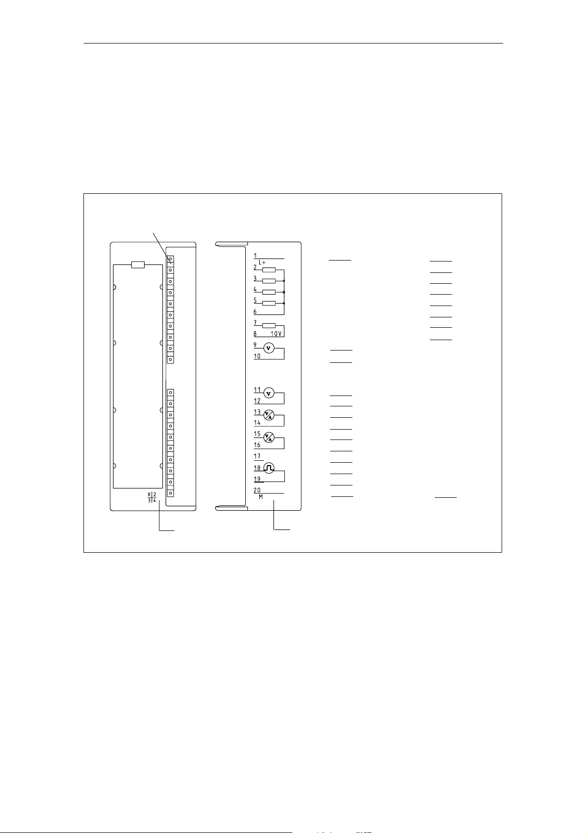
Terminal connection diagram
Figure 1-1 shows the terminal connections for the SM 335 analog input/output
module.
Fault LEDs – red
SF
Reserved
Analog inputs:
Voltage/
current measurement
L+
24 V
M
0+
CH0
M
0–
M
1+
CH1
M
1–
M
2+
CH2
M
2–
M
3+
CH3
M
3–
IZ
M
M
Interval counter IZ
IZ
M
Analog outputs:
Voltage output
Sensor
power
supply
L+
QV
QV
QV
QV
M
QV
M
M
0
1
2
3
ANA
Ref
ANA
24 V
CH0
CH1
CH2
CH3
10 V
M
Revision level
Connection
Diagram
Fig. 1-1 Terminal connection diagram of the SM 335
Wiring
See Chapter 2 and to the SIMATIC S7-300, Hardware and Installation Manual for
information about how to wire inputs and outputs on the SM 335.
SM 335 – High-Speed Analog Input/Output Module for the SIMATIC S7-300
6ES7 335-7HG00-8BA1
Terminal
1-3
Page 14

Characteristics and Technical Specifications of the SM 335
Revision Level
Products with the same number can be distinguished by the revision level.
The revision level is incremented by upwardly-compatible function expansions or
fault corrections.
The revision level of the module is identified by “X” (see Figure 1-1); in this case
the revision level is 1.
1-4
SM 335 – High-Speed Analog Input/Output Module for the SIMATIC S7-300
6ES7 335-7HG00-8BA1
Page 15
Characteristics and Technical Specifications of the SM 335
1.3 Block diagram of the SM 335
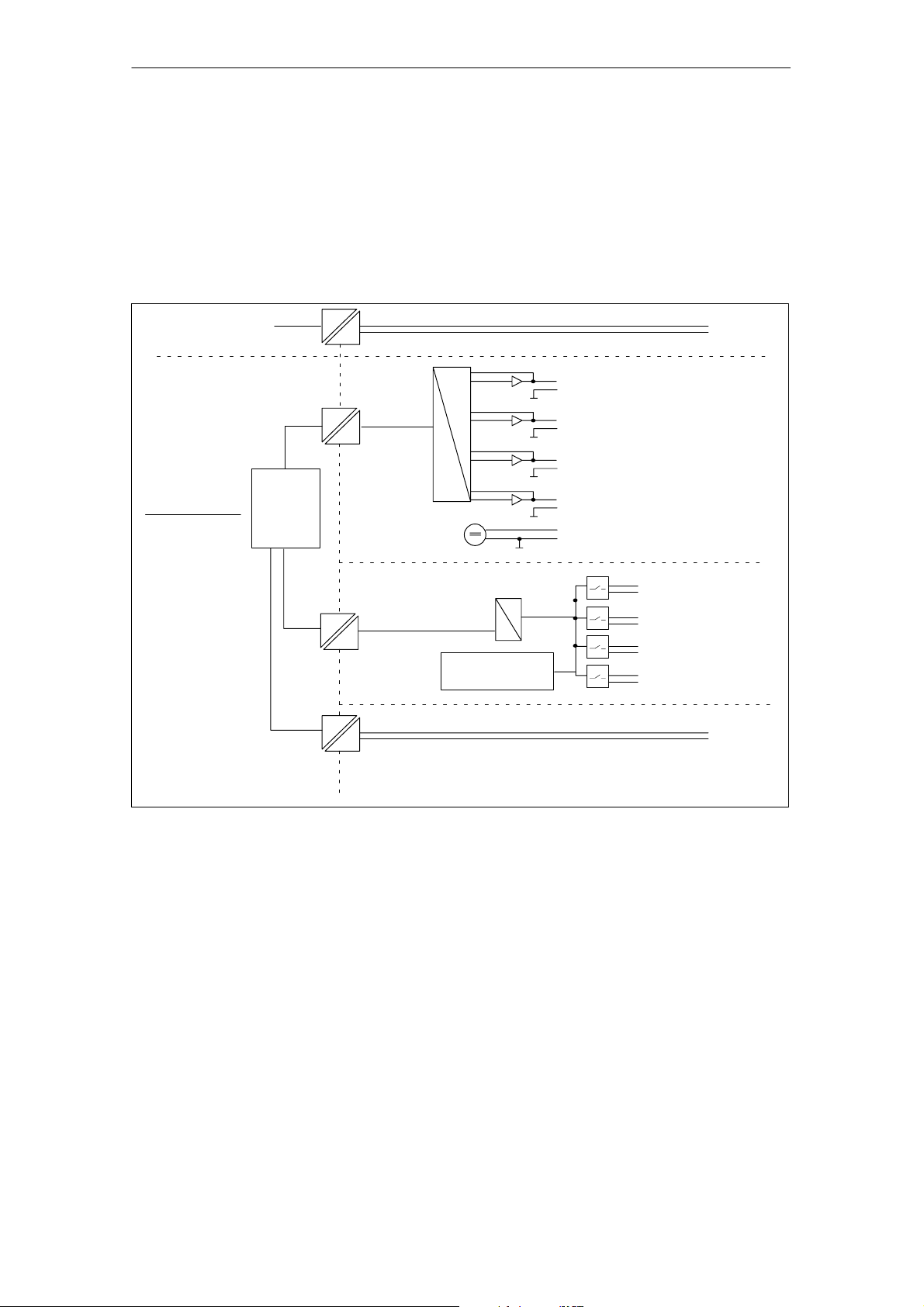
Block diagram
Figure 1-2 shows the block diagram of the SM 335. You will find detailed technical
specifications for the SM 335 on the following pages.
Internal power supply
SIMATIC S7-300
backplane bus
Galvanic isolation
Logic
A
D
Open-wire
test circuit
24 V
CH0
Analog outputs
CH1
CH2
CH3
10 V
Sensor power
supply
CH0
A
D
CH1
Analog inputs
CH2
CH3
IZ
Interval Counter Input
Fig. 1-2 Block Diagram of the SM 335
Galvanic isolation
As you can see from Figure 1-2, the SM 335 contains different analog parts.
The analog outputs are isolated from the backplane bus of the SIMATIC S7-300.
The outputs are on the same potential M
same potential M
as the analog outputs.
ANA
The analog inputs are isolated from each other and from the backplane bus of the
SIMATIC S7-300.
The input for the interval counter IZ is isolated from the other analog parts and
from the backplane bus of the SIMATIC S7-300.
SM 335 – High-Speed Analog Input/Output Module for the SIMATIC S7-300
6ES7 335-7HG00-8BA1
ANA
. The output for sensor supply has the
1-5
Page 16

Characteristics and Technical Specifications of the SM 335
1.4 Setting the measuring range with the measuring range module
Measuring range module
A measuring range module is located on the left of the input/output module. The
measuring range module is used to set the method of measuring on the analog
inputs, that is, to choose between voltage and current measuring.
Settings
The measuring range module can be set for “A”, “C” or “D”.
The default setting is “D”.
Table 1-1 shows the allocation of measuring range module settings to possible
connections of the analog inputs.
The measuring range is set using HW Config. You can select from different current
or voltage ranges (see Section 3.2).
The required measuring range module setting is also displayed in HW Config.
Table 1-1 Measuring range module settings and measuring range defaults on the
SM 335
Setting of the measuring
range module
A Input 0: Voltage "10 V
B Not assigned –
C Input 0: Voltage "10 V
D Input 0: Voltage "10 V
Analog input
wiring
Input 1: Voltage "10 V
Input 2: Voltage "10 V
Input 3: Current 4 to 20 mA
Input 1: Voltage "10 V
Input 2: Current 4 to 20 mA
Input 3: Current 4 to 20 mA
Input 1: Voltage "10 V
Input 2: Voltage "10 V
Input 3: Voltage "10 V
Measuring range
(default value)
1-6
SM 335 – High-Speed Analog Input/Output Module for the SIMATIC S7-300
6ES7 335-7HG00-8BA1
Page 17

Characteristics and Technical Specifications of the SM 335
1.5 Technical specifications for the SM 335
1.5.1 General technical specifications
Table 1-2 General technical specifications
Dimensions and weight
Dimensions W x H x D (mm) 40 x 125 x 120
Weight Approx. 300 g
Module-specific data
Number of inputs 4
Number of outputs 4
Cable length shielded 200 m
With open-wire test in the range 0 to 10 V 30 m
Voltages, currents, potentials
Rated load voltage L+
• Polarized
Galvanic isolation
Permissible potential difference
• Between inputs (U
• Between input (M terminal) and central
grounding point
• Isolation tested with 500 V DC
CM
)
3 V/1.5 V (10 V ranges)
24 V DC
Yes
Yes
75 V DC/60 V AC
Power consumption
• From SIMATIC S7-300 backplane bus
• From L+
• Module power loss
Status, interrupts, diagnostics
Interrupts
• Comparator interrupt
• End-of-cycle interrupt
• Diagnostic interrupt
Diagnostic functions
• Fault indication on the module in the event
of a group fault
• Diagnostic information can be read out
Miscellaneous
UL/CSA/FM Yes
Max. 75 mA
Max. 150 mA
Max. 3.6 W
NO
Yes, programmable
Yes, programmable
Yes, programmable
Yes, red LED
Yes
SM 335 – High-Speed Analog Input/Output Module for the SIMATIC S7-300
6ES7 335-7HG00-8BA1
1-7
Page 18

Characteristics and Technical Specifications of the SM 335
1.5.2 Technical specifications for the analog inputs
Table 1-3 Technical specifications for the analog inputs
Noise suppression and error limits for the inputs
Suppression of noise voltage for
f = n x (f1"1%), (f1 = interference frequency)
• Common-mode noise (U
• Series-mode noise
(peak noise value < rated value of the input range)
Crosstalk between inputs
• At 50 Hz
• At 60 Hz
Operational limit for voltage measuring
(over entire temperature range,
based on input range)
Operational limit for current measuring
(over entire temperature range, based on input range)
pp
< 3 V)
> 65 dB
0 dB
–65 dB
–65 dB
" 0.15%
(for 14-bit resolution)
0.25%
Basic error
(operational limit at 25 °C, based on input range)
Temperature drift (based on input range) " 0.13%
Linearity error (based on input range) " 0.015%
Repeatability
(in steady state at 25 °C, based on input range)
Sensor selection data
Input ranges (rated values)/input resistance
• Voltage
• Current (max. 2 channels)
Permissible input voltage for voltage input
(destruction limit)
Permissible input current for current input
(destruction limit)
Connecting of sensors
" 1 V
" 10 V
" 2.5 V
0 to 2 V
0 to 10 V
" 10 mA
0 to 20 mA
4 to 20 mA
• For measuring voltage
" 0.1%
(for 14-bit resolution)
" 0.05%
"30 V
25 mA
Possible
• For measuring current
– As 2-wire measuring transducer
– As 4-wire measuring transducer
• For measuring resistance
Not possible
Possible
Not possible
10 MW
10 MW
10 MW
10 MW
10 MW
100 W
100 W
100 W
1-8
SM 335 – High-Speed Analog Input/Output Module for the SIMATIC S7-300
6ES7 335-7HG00-8BA1
Page 19

Characteristics and Technical Specifications of the SM 335
Table 1-3 Technical specifications for the analog inputs
Analog value formation for the outputs
Measuring principle Successive approximation
Conversion time (per channel) in ms
• Basic conversion time for 4 channels in ms
Resolution
• Bipolar
• Unipolar
Data of output to sensor supply
Rated voltage 10 V
Max. output current 25 mA
Short-circuit-proof Yes
Operational limit
(over entire temperature range)
Temperature drift 0.002%/K
Basic error for rated voltage 0.1%
Max. 200
Max. 1
13 bits + sign
14 bits
0.2%
SM 335 – High-Speed Analog Input/Output Module for the SIMATIC S7-300
6ES7 335-7HG00-8BA1
1-9
Page 20

Characteristics and Technical Specifications of the SM 335
1.5.3 Technical specifications for the analog outputs
Table 1-4 Technical specifications for the analog outputs
Analog value formation for the outputs
Resolution (incl. overrange)
• " 10 V
• From 0 to 10 V
Conversion time in ms Max. 800
Setting time
• For resistive load
• For capacitive load
• For inductive load
Injection of substitute values Ye s
Noise suppression and error limits for the outputs
Crosstalk between outputs –40 dB
Operational limit (over entire temperature
range, based on output range)
Basic error
(operational limit at 25_C, based on output range)
Temperature drift
(based on output range)
Linearity error (based on output range) " 0.05%
Repeatability
(in steady state at 25 _C, based on output range)
Output ripple (based on output range) " 0.05%
Actuator Selection Data
Output range (rated values) " 10 V
Burden resistance
• For voltage outputs
• For capacitive load
• For inductive load
Voltage output
• Short-circuit protection
• Short-circuit current
Connection of actuators
• For voltage output
– 2-wire connection
– 4-wire connection (measuring circuit)
11 bits + sign
12 bits (+ sign)
t 0.1 ms
v 3.3 ms
t 0.5 ms
0.5%
0.2%
0.02%/K
" 0.05%
From 0 to 10 V
Min. 3 kW
Max. 1 mF
Max. 1 mH
Yes
Max. 8 mA
Possible
Not possible
1-10
SM 335 – High-Speed Analog Input/Output Module for the SIMATIC S7-300
6ES7 335-7HG00-8BA1
Page 21

Characteristics and Technical Specifications of the SM 335
1.5.4 Technical specifications for the interval counter
Table 1-5 Technical specifications for the interval counter
Interval-counter-specific data
Number of inputs 1
Cable length shielded 200 m
Voltages, currents, potentials
Rated load voltage L+
• Polarized
Galvanic isolation Yes
Permissible potential difference
• Interval counter input (M
to the four analog inputs
• Between input (M
point
Measuring principle Detection of a rising edge and
Resolution of the time difference 0.5 ms
Max. frequency
IZ
Analog value formation for the interval counter input
• Programmable
• Interference suppression for
interference frequency f1 in dB
Noise suppression and error limits for the input
Noise suppression for
F = n (f1 " 1%), (f1 = interference frequency)
• Common-mode noise (U
• Series-mode noise
(peak noise value t rated value of the input range)
Operational limit
(over entire temperature range)
Basic error
(operational limit at 25 oC)
Temperature drift (0 to 60 oC) " 0.003%/K
Linearity error 0
terminal)
IZ
terminal) and central grounding
t 3 V)
pp
75 V DC/60 V AC
75 V DC/60 V AC
measuring the amount of time
between two edges
Max. 1% at 400 Hz
24 V DC
Yes
400 Hz
NO
0
u 80 dB
0 dB
0.005%
SM 335 – High-Speed Analog Input/Output Module for the SIMATIC S7-300
6ES7 335-7HG00-8BA1
1-11
Page 22

Characteristics and Technical Specifications of the SM 335
Table 1-5 Technical specifications for the interval counter
Sensor selection data
Permissible input voltage (destruction limit) " 30 V
Permissible input current for interval input (destruction
limit)
Minimum permissible pulse widths at the counter input
• “Low”
• “High”
Permissible voltage range between IZ and MIZ terminals
• For “Low” pulse
• For “High” pulse
5 mA
1 ms
1 ms
– 30 V to + 5 V
(– 4.4 mA to 0.7 mA)
+ 18 V to + 30 V
(2.5 mA to 4.4 mA)
1-12
SM 335 – High-Speed Analog Input/Output Module for the SIMATIC S7-300
6ES7 335-7HG00-8BA1
Page 23

Characteristics and Technical Specifications of the SM 335
1.6 SM 335 operating modes
Operating modes
The SM 335 can operate in the following modes:
• Free cycle (corresponds to HW Config setting for SM 335: 0.5 ms cycle time)
• Conditional cycle (corresponds to HW Config setting for SM 335:
1 to 16 ms cycle time)
Special operating modes
In addition, the SM 335 can be switched to the following modes for a brief period of
time:
• “Comparator” special mode
• “Measuring Only” special mode
The special operating modes are described in Chapter 5, where there is also a description of how to switch to the special operating modes.
1.6.1 Free Cycle mode
Cycle
In conjunction with the SM 335, the word “cycle” is used to mean the measuring of
the analog value at all analog inputs in succession. Once the measuring cycle is
complete and all inputs have been read, the cycle starts again from the beginning.
This cycle has nothing to do with cyclic program scanning on a SIMATIC S7 CPU.
Free Cycle
When the SM 335 operates in Free Cycle mode, all SM 335 analog inputs and outputs are processed successively and without interruption. After all inputs and outputs have been processed, conversion once again begins with the first analog input.
Free Cycle mode is activated when a cycle time of 0.5 ms is set for the SM 335 in
HW Config.
SM 335 – High-Speed Analog Input/Output Module for the SIMATIC S7-300
6ES7 335-7HG00-8BA1
1-13
Page 24
Characteristics and Technical Specifications of the SM 335
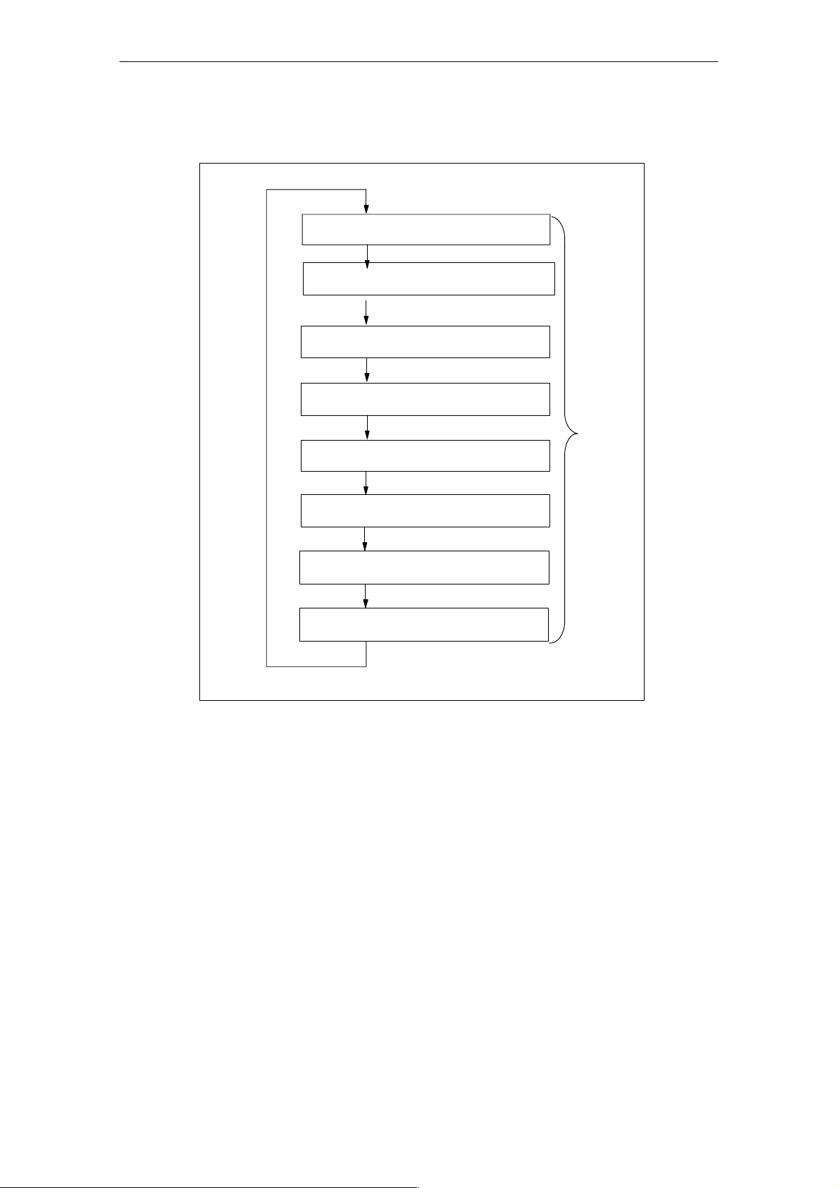
Figure 1-3 shows the various components of the cycle time for a free cycle.
Conversion time for analog input
channel CH3
Conversion time for analog input
channel CH2
Conversion time for analog input
channel CH1
Conversion time for analog input
channel CH0
Conversion time for analog output
channel CH3
Cycle
time
Conversion time for analog output
channel CH2
Conversion time for analog output
channel CH1
Conversion time for analog output
channel CH0
Fig. 1-3 Cycle time for the SM 335 free cycle
The execution times in Free Cycle mode are comprised as follows:
• Base load of a cycle: approx. 200 µs
• Execution times for the reading in of an analog channel: approx. 200 µs
• Execution time for the output of an analog value: approx. 50 µs
1-14
SM 335 – High-Speed Analog Input/Output Module for the SIMATIC S7-300
6ES7 335-7HG00-8BA1
Page 25

Characteristics and Technical Specifications of the SM 335
The SM 335 only updates the relevant analog output channel when modifications
are made to the output value.
• Four activated input channels and four activated output channels with the re-
quired output, which is dependent on constantly changing values, yields a cycle
time of 1200 µs (200 µs + 4 x 200 µs + 4 x 50 µs).
• Four activated input channels and four activated output channels with unchanged or rarely changing output values, yields a cycle time of 1000 µs
(200 µs + 4 x 200 µs + 4 x 0 µs).
• One activated input channel and four activated output channels with unchanged
or rarely changing output values, yields a cycle time of 400 µs (200 µs +
1 x 200 µs + 4 x 0 µs).
Deselecting diagnostics does not affect the cycle time.
SM 335 – High-Speed Analog Input/Output Module for the SIMATIC S7-300
6ES7 335-7HG00-8BA1
1-15
Page 26
Characteristics and Technical Specifications of the SM 335
1.6.2 Conditional Cycle mode
Conditional Cycle
In the conditional cycle operating mode, you can define the cycle time. Following conversion of all analog inputs, the SM 335 can generate an end-of-cycle interrupt to the CPU (see Subsection 3.4.1 Hardware Interrupt). The SM 335 then
waits while the analog outputs are updated and begins the next processing cycle
after the specified cycle time has expired.
The end-of-cycle interrupt can be used to synchronize a user program via OB 40.
Furthermore, the interrupt enables high-speed processing of the user program
(e.g., for closed-loop control routines).
Conditional Cycle mode is activated when a cycle time of 1 to 16 ms is set for the
SM 335 in HW Config.
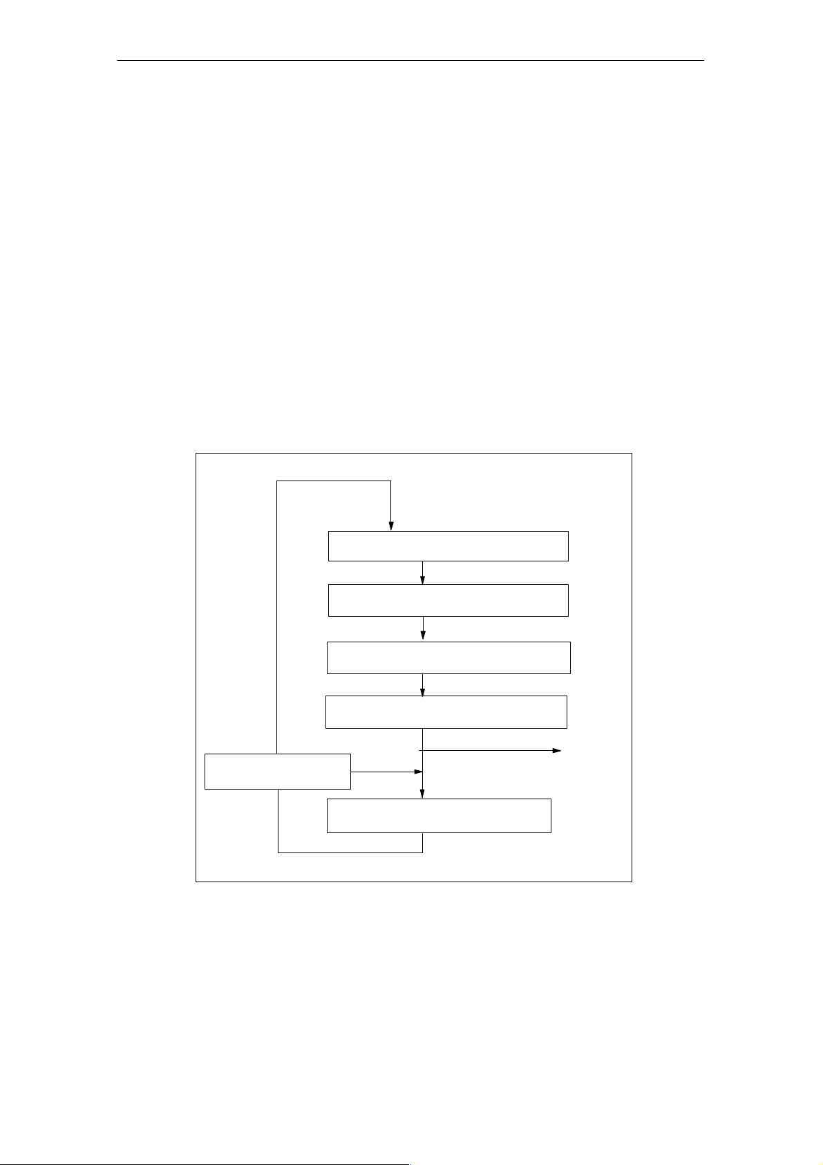
Figure 1-4 shows the various components of the cycle time for a conditional cycle.
Yes
Time condition:
Start new cycle
every 1 ms, 1.5 ms, etc., up to 16 ms
Conversion time for analog input
channel CH3
Conversion time for analog input
channel CH2
Conversion time for analog input
channel CH1
Conversion time for analog input
channel CH0
Optional
NO
Updating of the analog outputs
End-of-cycle
interrupt
1-16
Fig. 1-4 Cycle time for a conditional SM 335 cycle
SM 335 – High-Speed Analog Input/Output Module for the SIMATIC S7-300
6ES7 335-7HG00-8BA1
Page 27

Connecting the Inputs and Outputs of the SM 335
Assembly
Before connecting the SM 335, you must first assemble the SM 335. The SM 335
is assembled in the same way as all other SIMATIC S7-300 I/O modules. Please
read the SIMATIC S7-300 Hardware and Installation Manual.
SIMATIC S7-300
When connecting the SM 335, please note the installation guidelines in the
SIMATIC S7-300 Hardware and Installation Manual. In the SM 335 Manual, we
describe special features that only apply to the SM 335.
In this chapter
We deal with the following topics in this chapter:
2
Topic Section
Basic information about connecting the SM 335 2.1
Connecting the analog inputs 2.2
Connecting the analog outputs 2.3
Connecting the interval counter input 2.4
Connecting the sensor supply 2.5
Interference suppression filter for 24 V supply voltage 2.6
SM 335 – High-Speed Analog Input/Output Module for the SIMATIC S7-300
6ES7 335-7HG00-8BA1
2-1
Page 28

Connecting the Inputs and Outputs of the SM 335
2.1 Basic information about connecting the SM 335
Connecting the analog inputs and outputs
You can find detailed information about connecting the analog inputs and outputs in
the SIMATIC Programmable Logic Controller, S7-300 Module Data Reference Ma-
nual.
Rules
The following applies:
• The cables must be twisted-pair cables, protected against interference and
shielded.
• The accuracy of your measurements depends on the following:
– Load
Power supply
The SM 335 must be supplied with 24 V DC. The 24 V must be connected to
L+ (PIN 1), the 24 V’s zero potential to M (PIN 20).
Grounding
You can ground the 24 V power supply in the following way:
• Direct on the 24 V power supply unit or
• On the S7 CPU (if you use the 24 V power supply on the CPU).
– Cable between the SM 335 and the load
– Reference voltage
2-2
SM 335 – High-Speed Analog Input/Output Module for the SIMATIC S7-300
6ES7 335-7HG00-8BA1
Page 29
Connecting the Inputs and Outputs of the SM 335
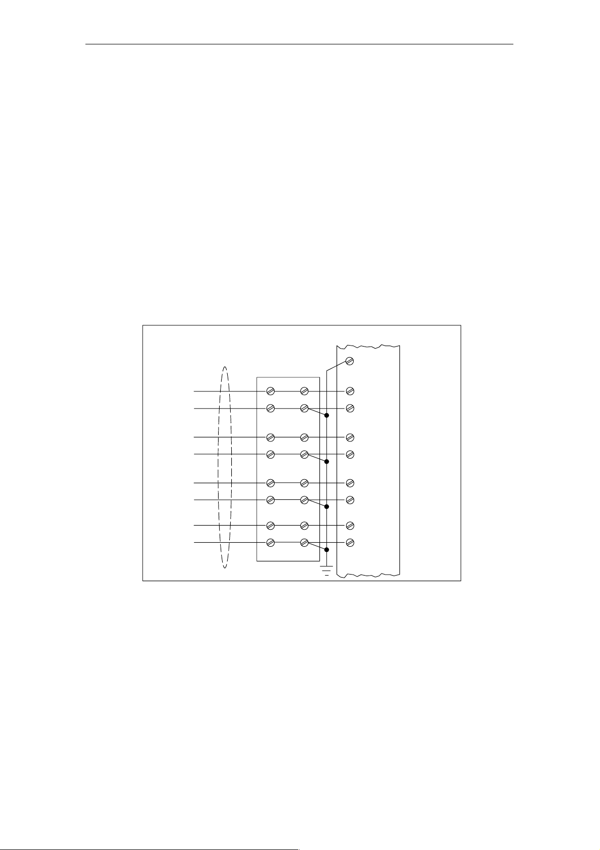
2.2 Connecting the analog inputs
Recommendation
The high conversion speed of the SM 335 means that the interference produced
can have a negative effect on the measurement input voltages in particular.
The configuration described below is in general the configuration, which is least
susceptible to interference.
The SM 335’s analog inputs and the associated zero potential should be connected to a terminal block, and the zero potential for the analog inputs distributed over the block.
Configuration
The result is the following basic configuration:
Twisted-pair,
shielded
Terminal block
Sensor 0
Sensor 1
Sensor 2
Sensor 3
Sensor 3
CGP=Central Grounding Point
Fig. 2-1 Connecting Sensors to the Analog Inputs on the SM 335
CGP
SM 335
6 M
ANA
9M
10 M
11 M
12 M
13 M
14 M
15 M
16 M
0+
0–
1+
1–
2+
2–
3+
3–
CH0
CH1
CH2
CH3
SM 335 – High-Speed Analog Input/Output Module for the SIMATIC S7-300
6ES7 335-7HG00-8BA1
2-3
Page 30

Connecting the Inputs and Outputs of the SM 335
Non-Isolated
In contrast to other applications (e. g., when connecting thermocouples), you
should ground the sensors’ analog zero potential in the vicinity of the SM 335. The
easiest way to do so is to connect pins 10, 12, 14 and 16 with analog zero potential
M
(PIN 6) and connect M
ANA
central grounding point (CGP) of the module. This connection should be as short
as possible.
Do not ground the sensors twice, however, as this would produce ground loops,
which could result in interference. When using sensors, which are shielded and
whose shields are connected to the analog zero potential, you must disconnect the
shield from the analog zero potential.
in the vicinity of the module in the rack with the
ANA
Limited potential difference U
Only a limited potential difference UCM (common mode voltage) may occur between the measuring lines M- of the input channels and the reference point of the
measuring circuit M
ANA
In order to prevent the permissible value being exceeded, you must take various
action, described below, depending on the potential connection of the sensors.
For details please see the SIMATIC Programmable Logic Controller, S7-300 Mod-
ule Data Reference Manual.
If you use the SM 335 isolated, the maximum permissible common mode voltage
must not be exceeded between the zero potential of the sensor and M
wise the SM 335 triggers a diagnostic alarm and 7FFFH is read in from the relevant
channel.
60 V AC/75 V DC must not be exceeded between M
24 V voltage supply.
Unused analog inputs
Unused analog inputs on the SM 335 must be short-circuited and connected to
M
. Deactivate the unused analog inputs as described in HW Config. This
ANA
achieves the optimum in interference immunity for the SM 335 and the cycle time
is reduced in the operating mode “free cycle”.
CM
.
and the ground of the
ANA
ANA
, other-
2-4
You can also employ unused analog inputs to monitor the sensor power supply or
analog outputs. This also enhances interference immunity.
SM 335 – High-Speed Analog Input/Output Module for the SIMATIC S7-300
6ES7 335-7HG00-8BA1
Page 31

Connecting the Inputs and Outputs of the SM 335
2.3 Connecting the analog outputs
Connecting the analog outputs
The analog outputs must be connected as voltage outputs. Detailed information can be found in the SIMATIC Programmable Logic Controller, S7-300 Module
Data Reference Manual.
Recommendation
If possible, the SM 335’s analog outputs, with the associated zero potential, should
be connected to a terminal block from where you can tap the zero potential for the
analog outputs.
Configuration
The result is the following basic configuration:
SM 335
CH0 2
CH1 3
CH2 4
CH3 5
M
6
ANA
Actuator 0
Actuator 1
Actuator 2
Actuator 3
Twisted-pair,
shielded
Fig. 2-2 Connecting Actuators to the SM 335
Non-Isolated
Actuators, which are shielded and whose shields are grounded and connected to
the actuator’s zero potential conductor, form a ground loop. You must therefore
break the connection between shield and zero potential conductor on the actuator
or use an actuator whose zero potential conductor is not connected to ground.
SM 335 – High-Speed Analog Input/Output Module for the SIMATIC S7-300
6ES7 335-7HG00-8BA1
2-5
Page 32

Connecting the Inputs and Outputs of the SM 335
Unused analog outputs
To ensure that unused analog outputs on the SM 335 are dead, you must deactivate them and leave them open. An analog output is deactivated with HW Config.
2.4 Connecting the interval counter input
Non-Isolated
If you wire the interval counter input as a non-isolated input, connect pin 19 (MIZ)
and pin 20 (24 V power supply’s zero potential).
Isolated
If you wire the interval counter input as an isolated input, you may not connect pin
19 (MIZ) to pin 20 (24 V power supply’s zero potential).
Additional information
See Section 4.3 for more information about connecting the interval counter input.
2-6
SM 335 – High-Speed Analog Input/Output Module for the SIMATIC S7-300
6ES7 335-7HG00-8BA1
Page 33

Connecting the Inputs and Outputs of the SM 335
2.5 Connecting the sensor power supply
Purpose
The sensor power supply is designed for resistance-type sensors (e. g., linear potentiometers).
Connections
Figure 2-3 shows an example of how to connect the sensor power supply.
SM 335
6 M
ANA
10 V
0 V
Fig. 2-3 Example of How to Supply the Sensors with Power via the SM 335
Non-isolated configuration
Internally, the SM 335’s analog zero potential (pin 6) is connected with the 10 V
sensor power supply’s zero potential.
7 10 V
U
=10 V
Ref
U
8
9M
10 M
0+
0–
Sensor
power
supply
Measuring
signal
If you use the four-wire measuring method shown in Figure 2-3, you must not connect pin 10 to pin 6 or to zero potential. To do so would create a ground loop,
which could cause interference.
SM 335 – High-Speed Analog Input/Output Module for the SIMATIC S7-300
6ES7 335-7HG00-8BA1
2-7
Page 34

Connecting the Inputs and Outputs of the SM 335
Cable
There is a voltage drop on the cable between SM 335 and the linear potentiometer.
Because of the SM 335’s high resolution, this can play a role in the measuring of
the analog signal. You can compute the voltage drop on an electric cable as follows:
U: Voltage drop along the cable
: Resistivity of the cable used
r
0
r0· I · L
U +
A
Because of this, we would recommend keeping the cables as short as possible
and using a cable with the largest possible cross-section.
(for Cu: 0,0172 W mm2/m)
I: Current flowing through the cable in
amperes
L: Length of the cable in meters
A: Cross-section of the cable in mm
2
2-8
SM 335 – High-Speed Analog Input/Output Module for the SIMATIC S7-300
6ES7 335-7HG00-8BA1
Page 35

Connecting the Inputs and Outputs of the SM 335
2.5.1 Correcting the sensor power supply
Purpose
The power supply for the sensors is a 10 V output voltage. This voltage may deviate slightly from 10 V. The deviation results from the tolerances of the components
used on the SM 335. You can therefore read off the exact value of the sensor
power supply for applications requiring very high accuracy.
Sensor voltage (ModAdd + 10, 11)
The analog value of the sensor voltage (UG) is factory-set and stored in the module. The SM 335 supplies the analog value of the sensor voltage UG in input bytes
ModAdd + 10 and ModAdd + 11 (see Table 3-1 in Subsection 3.1.1).
Correction factor
The correction factor K is computed from the sensor voltage UG and the desired
voltage.
27648 (6C00H)
K +
UG lies between 27620 (6BE4H) and 27676 (6C1CH), producing correction factors
from 0.9989883 to 1.0010127.
Measured value
The corrected analog measured value is computed as follows:
U
+ K · U
Corr
U
G
U
= Corrected analog value
Corr
K = Correction factor
AI
= Analog value measured at the analog input
U
AI
SM 335 – High-Speed Analog Input/Output Module for the SIMATIC S7-300
6ES7 335-7HG00-8BA1
2-9
Page 36

Connecting the Inputs and Outputs of the SM 335
2.6 Interference suppression filter for 24 V supply voltage
Caution
The SM 335 module must always be used with an interference suppression filter to
obtain interference immunity for SIMATIC.
Interference
Interference may reach the SM 335 via the 24 V voltage supply. One cause of
such interference is the switching of loads connected to the 24 V circuit. The interference has a high-frequency content, which can impair proper functioning of the
SM 335.
2-10
SM 335 – High-Speed Analog Input/Output Module for the SIMATIC S7-300
6ES7 335-7HG00-8BA1
Page 37

Interference suppression filter
The SM 335 is protected from the high-frequency content by an interference suppression filter. Connect this filter to the 24 V voltage supply circuit of the SM 335
module (see Figure 2-4).
Connecting the Inputs and Outputs of the SM 335
Interference
Suppression
Filter
SM 335
L+
24 V
power
supply
M
Other modules
Fig. 2-4 Interference Suppression Filter for the 24 V Power Supply of the
SM 335
1
2 2’
1’
1L
+
20 M
Other analog
modules that
generate no
interference
The interference suppression filter can be used for a maximum of 4 SM 335 modules and should be located as close as possible to the SM 335.
The interference suppression filter is brought into the 24 V supply circuit even if it
can be used with a higher voltage.
The interference suppression filter can be obtained by quoting order number:
6ES7 335-7HG00-6AA0
Type: e. g., EPCOS SIFI C, order reference B84113-C-B30
Please contact your local Siemens representative for more information.
SM 335 – High-Speed Analog Input/Output Module for the SIMATIC S7-300
6ES7 335-7HG00-8BA1
2-11
Page 38

Connecting the Inputs and Outputs of the SM 335
2-12
SM 335 – High-Speed Analog Input/Output Module for the SIMATIC S7-300
6ES7 335-7HG00-8BA1
Page 39

Data Exchange with the SM 335
Preliminary remark
Data exchange with the SM 335 is defined here as follows:
• Transfer of data to the SM 335 from the CPU and
• Reading of data from the SM 335 by the CPU.
Overview
In this chapter, we have summarized all the data that can be transferred to the
SM 335 or supplied by the SM 335.
Methods
There are basically several methods of reading or writing data:
• Access via the I/O addresses (e. g., with L PIW, T PQW)
• Setting parameters via HW Config
3
• Writing parameters with the help of system function 55
• Reading diagnostics data via system function 59
• Other methods: see Reference Manual
System Software for S7-300/400 System and Standard Functions.
Measuring range module
Before you plug in the SM 335, you must insert the measuring range module into
the SM 335. The SIMATIC Programmable Logic Controller, S7-300 Module Data
Reference Manual describes how to insert the measuring range module into the
SM 335.
The measuring method (current/voltage measurement) is set for the analog inputs
depending on the position in which you plug in the measuring range module.
SM 335 – High-Speed Analog Input/Output Module for the SIMATIC S7-300
6ES7 335-7HG00-8BA1
3-1
Page 40

Data Exchange with the SM 335
In this chapter
We deal with the following topics in this chapter:
Access via the I/O addresses 3.1
Setting parameters via HW Config 3.2
Topic Section
Modifying SM 335 parameters with the help of system func-
3.3
tion 55
Evaluating SM 335 diagnostics 3.4
3-2
SM 335 – High-Speed Analog Input/Output Module for the SIMATIC S7-300
6ES7 335-7HG00-8BA1
Page 41

3.1 Access via the I/O addresses
Principle
You can access the SM 335 via I/O addresses.
Input values
Input values are values supplied by the SM 335. The input values contain measured values of the SM 335.
You can load the input values via L PIB (or L PIW or L PID) operation. As an alternative, read access is possible within the process image via L IB (or L IW or L ID).
(see Table 3-1, Subsection 3.1.1)
Output values
Data Exchange with the SM 335
Output values are values you write to the SM 335 via T PQB (or T PQW or T PQD)
operation. As an alternative, write access is possible within the process image via
T IB (or T IW or T ID).
You can transfer analog values to the SM 335 via output values. The output values
are output via the SM 355’s analog outputs. (see Table 3-4, Subsection 3.1.2)
3.1.1 Output values
Principle
The SM 335 converts the signals measured at the inputs into binary values.
SM 335 – High-Speed Analog Input/Output Module for the SIMATIC S7-300
6ES7 335-7HG00-8BA1
3-3
Page 42

Data Exchange with the SM 335
Configuration
The input values are located in bytes ModAdd (module start address) to ModAdd + 15. See the SIMATIC Programmable Logic Controller, S7-300 Module Data
Reference Manual for information about how to compute the module start address.
Table 3-1 lists the input values, their addresses, and their default values.
Table 3-1 SM 335 Input Values
Byte
ModAdd + 0 High-order byte of the measuring value from measuring
channel CH0
ModAdd + 1 Low-order byte of the measuring value from measuring
channel CH0
ModAdd + 2 High-order byte of the measuring value from measuring
channel CH1
ModAdd + 3 Low-order byte of the measuring value from measuring
channel CH1
ModAdd + 4 High-order byte of the measuring value from measuring
channel CH2
ModAdd + 5 Low-order byte of the measuring value from measuring
channel CH2
ModAdd + 6 High-order byte of the measuring value from measuring
channel CH3
ModAdd + 7 Low-order byte of the measuring value from measuring
channel CH3
ModAdd + 8 Number of end-of-cycle interrupts, only for “Comparator”
and “Measuring Only” modes
Default = 1;
If end-of-cycle interrupts have been suppressed:
1 + number of suppressed end-of-cycle interrupts
ModAdd + 9 Comparator mode (on power-up) or Return code for
“Comparator” and “Measuring Only” modes.
ModAdd + 10 High-order byte of the sensor voltage (see Subsec-
tion 2.5.1)
ModAdd + 11 Low-order byte of the sensor voltage (see Subsec-
tion 2.5.1)
ModAdd + 12 Interval counter (see Section 4.5) 00H *) or ***)
ModAdd + 13 Interval time values in bits 16 to 24 (see Section 4.5) FF
ModAdd + 14 Interval time values in bits 8 to 15 (see Section 4.5) FF
ModAdd + 15 Interval time values in bits 0 to 7 (see Section 4.5) FF
Content Value
7FH *) or ***)
FFH *) or ***)
7FH *) or ***)
FFH *) or ***)
7FH *) or ***)
FFH *) or ***)
7FH *) or ***)
FFH *) or ***)
00H *) or ***)
00H *) or
01H *) or ***)
**)
**)
*) or ***)
H
*) or ***)
H
*) or ***)
H
*) Initial value
**) factory-set
***) current value
Analog values (ModAdd + 0...7)
See Subsections 3.1.3 and 3.1.4 for information about how an analog value is represented in binary in the CPU and on which binary value corresponds to which
analog value.
3-4
SM 335 – High-Speed Analog Input/Output Module for the SIMATIC S7-300
6ES7 335-7HG00-8BA1
Page 43

Number of end-of-cycle interrupts (ModAdd + 8)
A user program can be synchronized via OB 40 using the end-of-cycle interrupt.
Fast processing of the user program is also possible via the interrupt (e. g., for adjustment routines).
There are however situations in which the SM 335 cannot send an interrupt:
• when several hardware interrupts occur simultaneously, or
• in the special “Comparator” mode.
The SM 335 suppresses end-of-cycle interrupts when the Comparator mode is enabled.
The SM 335 enters the number of suppressed end-of-cycle interrupts (1 + number
of suppressed end-of-cycle interrupts) in byte ModAdd + 8 when the “Comparator
mode” is exited.
Example: Content of byte 8 = 5, i. e., for 5 end-of-cycle interrupts, OB 40 is called
only once.
The value is also stored in the local data of OB 40 (see Subsection 3.4.1, Hardware interrupt). Evaluation via OB 40 has the advantage of ensuring the consistency of the measured value and the number end-of-cycle interrupts.
Data Exchange with the SM 335
Return code (ModAdd + 9)
When the “Comparator” or “Measuring Only” mode is activated, the SM 335
SM 335 enters the return code in byte ModAdd + 9. Figure 3-1 shows the format of
the return code:
76543210
Comparator is active/was last active mode
Measuring Only is active/was last active mode
Measuring Only/Comparator mode activated
Fig. 3-1 SM 335 Return Codes
The return code bits, with their descriptions, are shown in Table 3-2.
Comparator mode is displayed instead of the return code on power-up of the
SM 335.
Error code
Measured value not current
Parameter assignment error
SM 335 – High-Speed Analog Input/Output Module for the SIMATIC S7-300
6ES7 335-7HG00-8BA1
3-5
Page 44

Data Exchange with the SM 335
Table 3-2 Meaning of the bits in the SM 335 return code
Bit
Description
7 = 1: SM 335 is in “Measuring Only” or “Comparator” mode
= 0: SM 335 is in “Conditional Cycle” or “Free Cycle” mode
1)
6
5
= 1: “Measuring Only” mode is activated / was last activated
1)
= 1: “Comparator” mode is activated / was last activated
4 = 1: Mode cannot be activated. Reason:
• The “Comparator” mode cannot be activated when “Measuring Only” mode
is enabled.
• The “Measuring Only” mode cannot be activated when the “Comparator”
mode is enabled or when the “Measuring Only” mode is already active.
3 = 1: The measured value from the analog inputs is not current
(for “Comparator” mode only – with Comparator 2, see Subsection 5.2.1,
Principle of special “Comparator” mode)
2, 1, 0 Error code see Table 3-3
1)
Only bit 5 or 6 can be set but not both
Table 3-3 Description of Bits 0, 1, 2 in the Return Code of the SM 335
Bit2 Bit1 Bit0 Description
0 0 0 No error
0 0 1 Parameter for operating mode ‘Comparator’ faulty
(no analog input designated as comparator input).
0 1 0 Analog input to be used for measuring is disabled.
0 1 1 Error detected at the analog input assigned to the comparator while
‘Comparator’ mode was in force.
1 0 0 Operating mode exited. Reason:
• Comparator: Comparator time expired (see Subsection 5.2.2)
• Measuring Only (see Section 5.3 ):
Measurement at one analog input: 60 ms expired.
Measurement at 2, 3 or 4 analog inputs: 40 ms expired.
1 0 1 “Comparator” mode exited because new parameters were transferred
via system function to the SM 335.
3-6
SM 335 – High-Speed Analog Input/Output Module for the SIMATIC S7-300
6ES7 335-7HG00-8BA1
Page 45

3.1.2 Output values
Principle
The analog output values converted into binary in the CPU can be transferred to
the SM 335 e. g., with the command “T PQW”.
The SM 335 converts the binary form of the analog output signals into analog signals and forwards them to the relevant outputs.
Configuration
The output values can be transferred to bytes ModAdd (module start address) to
ModAdd + 7 (module start address + 7).
See Configuring the SM 335 in HW Config from STEP 7 onwards for how to compute the module start address.
Data Exchange with the SM 335
Table 3-4 SM 335 Output Values
ModAdd + 0 High-order byte of the output value for analog output channel CH0
ModAdd + 1 Low-order byte of the output value for analog output channel CH0
ModAdd + 2 High-order byte of the output value for analog output channel CH1
ModAdd + 3 Low-order byte of the output value for analog output channel CH1
ModAdd + 4 High-order byte of the output value for analog output channel CH2
ModAdd + 5 Low-order byte of the output value for analog output channel CH2
ModAdd + 6 High-order byte of the output value for analog output channel CH3
ModAdd + 7 Low-order byte of the output value for analog output channel CH3
Analog values
See Subsections 3.1.3 and 3.1.4 for information about how an analog value is represented in binary in the CPU and on which binary value corresponds to which
analog value.
Byte
Content
SM 335 – High-Speed Analog Input/Output Module for the SIMATIC S7-300
6ES7 335-7HG00-8BA1
3-7
Page 46

Data Exchange with the SM 335
3.1.3 Analog value representation for analog input channels
The tables contain representations of the measuring values of individual measuring
ranges of the analog inputs.
Table 3-5 Analog Value Representation in the Bipolar Input Ranges
Measuring Range
Units Range
+ 1 V + 10 V + 2.5 V + 10 mA decimal hexa-
1.185 V
:
:
1,1758 V
:
:
1 V
:
0.75 V
:
144.68 µV
0 V
–144.68 µV
:
–0.75
:
–1 V
:
:
–1.176 V
:
:
–1.185 V
11.851 V
:
:
11,758 V
:
:
10 V
:
7.5 V
:
1446.8 µV
0 V
–1446.8 µV
:
–7.5 V
:
–10 V
:
:
–11.759 V
:
:
–11.851 V
2.963 V
:
:
2,938 V
:
:
2.5 V
:
1.875 V
:
361.69 µV
0 V
–361.69 µV
:
–1.875 V
:
–2.5 V
:
:
–2.940 V
:
:
–2.963 V
11,85 mA
:
:
11,758 mA
:
:
10 mA
:
7.5 mA
:
1446.8 nA
0 mA
–1446.8 nA
:
–7.5 mA
:
–10 mA
:
:
–11.76 mA
:
:
–11.85 mA
32767
:
32512
32508
:
27652
27648
:
20736
:
4
0
–4
:
–20736
:
–27648
–27652
:
–32512
–32516
:
–32768
decimal
7FFF
:
7F00
7EFC
:
6C04
6C00
:
5100
H
:
4
H
0
FFFC
:
AF00
:
9400
H
93FC
:
8100
H
80FC
:
8000
H
H
H
H
H
H
H
H
H
H
Overflow
Overrange
Rated
range
Underrange
Underflow
3-8
SM 335 – High-Speed Analog Input/Output Module for the SIMATIC S7-300
6ES7 335-7HG00-8BA1
Page 47

Data Exchange with the SM 335
Table 3-6 Analog Value Representation in the Unipolar Input Ranges
Measuring Range
Units Range
0 – 2 V 0 –10 V 0 – 20 mA 4 – 20 mA decimal hexa-
decimal
2.370 V
:
:
2.35 V
:
:
2 V
:
1.5 V
:
144.68 µV
11.852 V
:
:
11,75 V
:
:
10 V
:
7.5 V
:
723.4µV
23.70 mA
:
:
23.5 mA
:
:
20 mA
:
15 mA
:
1446.8 nA
22.96 mA
:
:
22.8 mA
:
:
20 mA
:
15 mA
:
4 mA +
32767
:
32512
32510
:
27650
27648
:
20736
:
2
7FFF
:
7F00
7EFE
:
6C02
6C00
:
5100
:
2
H
1157.4 nA
0 V
–144,68 µV
:
–18.446 mV
0 V
–723,4 µV
:
–92.223 mV
0 mA
1446.8 nA
:
18.448 µA
4 mA
<4 mA
Open wire
(7FFFH)
0
–2
:
–255
0
FFFE
:
FF00
<–18.446 mV <–92.223 mV <–18.448 µA –32768 8000
H
H
H
H
H
H
H
H
H
Overflow
Overrange
Rated range
Underrange
Underflow
SM 335 – High-Speed Analog Input/Output Module for the SIMATIC S7-300
6ES7 335-7HG00-8BA1
3-9
Page 48

Data Exchange with the SM 335
3.1.4 Analog value representation for analog output channels
The table contains the analog value representation of the SM 335’s output channels.
12 bits (+VZ) of the output value are converted in the 0-10 Volt range.
Bit 0, Bit 1 and Bit 2 are not converted.
11 bits + VZ of the output value are converted in the + 10 Volt range.
Bit 0, Bit 1, Bit 2 and Bit 3 are not converted.
Table 3-7 Analog Value Representation in the Output Ranges from 0 to 10 V and + 10 V
Output Value
decimal hexa-
32767
:
32512
32504
32496
:
27664
27656
27648
:
20736
:
16
8
0
–8
–16
:
–20736
:
–27648
–27656
–27648
:
–32496
–32504
–32512
:
–32768
7FFF
:
7F00
7EF8
7EF0
:
6C10
6C08
6C00
:
5100
:
10
8
H
0
H
FFF8
FFF0
:
AF00
:
9400
93F8
93F0
:
8110
8108
8100
:
8000
decimal
H
H
H
H
H
H
H
H
H
H
H
H
H
H
H
H
H
H
H
Range Output Voltage
0-10 V +10 V
Overflow
(off circuit and de-energized)
0 V
:
0 V
Overrange 11.756 V
11.753 V
:
10.006 V
10.003 V
Rated range 10 V
:
7.5 V
:
5.787 mV
2.8936 mV
0 V
0 V
0 V
:
0 V
:
0 V
Underrange 0 V
0 V
:
0 V
0 V
Underflow
(off circuit and de-energized)
0 V
:
0 V
0 V
:
0 V
11.753 V
11.753 V
:
10.006 V
10 V
10 V
:
7.5 V
:
5.787 mV
0 V
0 V
0 V
–5.787 mV
:
–7.5 V
:
–10 V
–10 V
–10.006 V
:
–11.753 V
–11.753 V
0 V
:
0 V
3-10
SM 335 – High-Speed Analog Input/Output Module for the SIMATIC S7-300
6ES7 335-7HG00-8BA1
Page 49

3.2 Setting parameters via HW Config
Measuring Range Module
You must plug in the measuring range module into the side of the SM 335.
You can learn how to do this in Reference Manual SIMATIC Programmable Logic
Controller, S7-300 Module Data. Section 1.4 describes the measuring ranges to be
set.
HW Config
Certain features of the SM 335 (e. g., cycle time, A/D conversion) are explained in
HW Config, Parameter Assignment of STEP 7.
The measuring range modules in the module must also be set to the necessary
settings if required (see Section 1.4).
Data Exchange with the SM 335
SM 335 – High-Speed Analog Input/Output Module for the SIMATIC S7-300
6ES7 335-7HG00-8BA1
3-11
Page 50

Data Exchange with the SM 335
3.2.1 SM 335 default settings
Default settings
The analog input/output module has default settings. These default settings are
used when no parameters are set using the STEP 7 “HW Config” tool.
The defaults are listed in table 3-8.
Table 3-8 SM 335 Default Settings
Parameters
Cycle time *) Free Cycle (equivalent to 0.5 ms
Measuring method U or I (4 DMU) as per measuring
Measuring Range with U: +/– 10 V
Diagnostic interrupt *) no no
Hardware interrupt on
end-of-cycle
Group diagnostics
(= short-circuit test on analog output)
Open-wire test no –
Response with CPU-STOP – OCV (output have no cur-
Number of active channels 4 4
*) Setting is valid for entire module.
Default Setting for
Analog Inputs
[SM 335 cycle time] setting)
range module setting (see
Table 1-1)
with I (4 DMU): 4 - 20 mA
no no
no no
Default Setting for Analog
Outputs
U
+/– 10 V
rent or voltage)
3-12
SM 335 – High-Speed Analog Input/Output Module for the SIMATIC S7-300
6ES7 335-7HG00-8BA1
Page 51

Data Exchange with the SM 335
3.2.2 SM 335 parameters assignable with HW Config
Parameter assignment application
The STEP 7 tool used to initialize the analog modules in a STEP 7 environment is
called “HW Config”.
SM 335 parameters
Table 3-9 provides an overview of the SM 335 parameters which can be assigned
with HW Config.
Table 3-9 SM 335 parameters in HW Config
Parameters
Basic settings for inputs
• Hardware interrupt for end-of-cycle
• Diagnostic interrupt enable
Diagnostics for inputs: Enable
includes:
Value Range Default
yes/no
yes/no
yes/no no
SM 335
no
no
• Measuring range underrange
• Measuring range overrange
• Overrange of permitted common mode
voltage
Open-wire test yes/no no
Measurement
• Method Deactivated
Voltage
Current (4-wire trans-
ducer)
Voltage
• Range Voltage: " 1 V; " 2.5 V; 0 to 10 V;
0 V to + 2 V (channel CH0 to CH3)
default" 10 V;
Current: " 10 mA; 0 mA to + 20 mA
+ 4 mA to + 20 mA (channel CH2 to CH3)
• Cycle time for A/D conversion 0,5;
Diagnostics for outputs (short-circuit test) yes/no no
Response with CPU-STOP “Keep last value
*)
The setting 0.5 ms in HW Config means: Free Cycle
The setting of 1 to 16 ms in HW Config means: Conditional Cycle
*)
1 to 16 ms 0.5 ms
(KLV)” or
“Output have no cur-
rent or voltage
(OCV)”
“Output have no
current or voltage
(OCV)”
*)
SM 335 – High-Speed Analog Input/Output Module for the SIMATIC S7-300
6ES7 335-7HG00-8BA1
3-13
Page 52

Data Exchange with the SM 335
Table 3-9 SM 335 parameters in HW Config
Parameters SM 335Parameters
Output
• Method Deactivated / Voltage Voltage
• Range from – 10 V to + 10 V
*)
The setting 0.5 ms in HW Config means: Free Cycle
The setting 1 to 16 ms in HW Config means: Conditional Cycle
End-of-cycle interrupt enable
When you enable the end-of-cycle interrupt, the SM 335 generates a hardware
interrupt after A/D conversion of the active channels. You can use this to call OB
40 at fixed intervals. You can set the cycle time for the A/D conversion. The
SM 335 can generate the end-of-cycle interrupt starting from a cycle time for A/D
conversion of 1 ms.
(see Subsection 3.4.1, Hardware Interrupt)
DefaultValue Range
from 0 V to + 10 V
Diagnostic interrupt enable
When diagnostic interrupts are enabled, the SM 335 generates a diagnostic interrupt as soon as an error is found.
Enable diagnostics
If the diagnostics for inputs are enabled, the SM 335 checks for common-mode
errors and measuring range violations. When you enable diagnostics for the outputs, the SM 335 executes a short-circuit test on the outputs.
Open-wire test
You can activate the open-wire test for any analog input.
An open-wire test is possible in measuring ranges:
• 0 to 10 V (when the A/D conversion cycle time is 2 ms or longer)
• 4 to 20 mA (when the A/D conversion cycle time is 1.5 ms or longer or with
Free Cycle).
3-14
SM 335 – High-Speed Analog Input/Output Module for the SIMATIC S7-300
6ES7 335-7HG00-8BA1
Page 53

Response with CPU-STOP
When the CPU is at STOP or executing the startup routine, the SM 335 outputs
the substitute value to the relevant analog output until a new value is specified.
The SM 335 uses the following as a substitute value:
• 0 V
(if “Outputs off circuit and de-energized” has been set in HW Config) or
• the analog value last output
(if “Retain last value” has been set in HW Config).
Data Exchange with the SM 335
SM 335 – High-Speed Analog Input/Output Module for the SIMATIC S7-300
6ES7 335-7HG00-8BA1
3-15
Page 54

Data Exchange with the SM 335
3.3 Modifying SM 335 parameters with the help of system function 55
HW Config
In RUN mode of the CPU, you can modify some parameters (dynamic parameters)
via system function 55.
For other methods of modifying parameters: see Reference Manual System Soft-
ware for S7-300/400 System and Standard Functions.
Parameters
The SM 335 parameters are 16 bytes long and are divided into two data records
(DR0 and DR1).
The SM 335 parameters (complete DR1 to be transferred to the module) must be
stored in a data area on the CPU (e.g., in a bit memory or data block). System
function 55 WR_PARAM is used to transfer the parameters to the SM 335.
Note
You must always initialize the SM 335 parameters with HW Config before
transferring them with system function 55.
Reason: The system function accesses SDB 1XX, which is generated with
HW Config.
Data Records
The SM 335 parameters are stored in two data records (DR0 and DR1).
Data Record 0 (DR0)
Data record 0 of the SM 335 is 2 bytes long and contains the static parameters of
the SM 335. You cannot modify these parameters with system function 55.
Data Record 1 (DR1)
Data record 1 contains the dynamic parameters of the SM 335. SM 335. You can
modify these parameters with system function 55.
The complete data record 1 (bytes 0 to 13) must always be transferred.
3-16
SM 335 – High-Speed Analog Input/Output Module for the SIMATIC S7-300
6ES7 335-7HG00-8BA1
Page 55

3.3.1 SM 335 static parameters
The static parameters can only be modified via HW Config.
Data Record 0
Data record 0 of the SM 335 contains static parameters (see Table 3-10)
Table 3-10 SM 335 parameters in Data Record 0
Data Exchange with the SM 335
Diagnostics
Byte
0 Input and output diagnostics 00
1 Reserved 00
Content Default
H
H
The “Input and output diagnostics” parameter is used to specify in HW Config
which analog inputs and outputs are to trigger a diagnostic interrupt in the event of
an error.
76543210
Analog output CH3
Analog output CH2
Analog output CH1
Analog output CH0
= ’1’: Diagnostic interrupt enabled
= ’0’: Diagnostic interrupt disabled
Fig. 3-2 Meaning of the bits in the “input and output diagnostics” byte
Analog input CH3
= ’1’: Diagnostic interrupt enabled
= ’0’: Diagnostic interrupt disabled
Analog input CH0
Analog input CH1
Analog input CH2
If the diagnostics for inputs are enabled, the SM 335 checks for common-mode
errors and measuring range violations.
When you enable diagnostics for the outputs, the SM 335 executes a short-circuit
test on the outputs.
SM 335 – High-Speed Analog Input/Output Module for the SIMATIC S7-300
6ES7 335-7HG00-8BA1
3-17
Page 56

Data Exchange with the SM 335
3.3.2 SM 335 parameters in the Free Cycle and Conditional Cycle
Modes
Data Record 1 (DR1)
Data record 1 (DR1) of the SM 335 contains dynamic parameters (see Table 3-11).
The parameters are set via HW Config, or can be modified via system function 55.
Data record DR1 must always be completely transferred using system function 55.
Table 3-11 SM 335 parameters in Data Record 1 (DR1)
Byte
Content Default
0 Interrupt and substitute value output 00
1 Reserved 00
2 Measuring range for analog input channel
CH0
3 Measuring range for analog input channel
CH1
4 Measuring range for analog input channel
CH2
5 Measuring range for analog input channel
CH3
depends on
measuring range mod-
ule setting
(see Table 3-12)
6 Output range for analog output channel CH0 19
7 Output range for analog output channel CH1 19
8 Output range for analog output channel CH2 19
9 Output range for analog output channel CH3 19
10 Measuring cycle time 01
11 Dynamic measurement cycle control:
fixed in Free Cycle and
Conditional Cycle modes: 00
H
12 Open-wire test 00
13 Factor for interval counter monitoring time
(see Section 4.4)
19
19
00
00
H
H
H
H
H
H
H
H
H
H
H
H
3-18
SM 335 – High-Speed Analog Input/Output Module for the SIMATIC S7-300
6ES7 335-7HG00-8BA1
Page 57

Interrupt and substitute value output (DR1, Byte 0)
The interrupt and substitute value output parameter defines the following:
• Whether a hardware interrupt (conditional cycle only) is to be generated
• Whether a diagnostics interrupt is to be generated
• Whether the last valid analog value or 0 V is to be output as a substitute value
The hardware and diagnostic interrupt settings are effective on all module channels.
76543210
76543210
Enable hardware interrupt
with end-of-cycle
Enable diagnostic
interrupt
= 1: Substitute value = Last analog value
= 0: Substitute value 0 V is output
Analog output CH3
Data Exchange with the SM 335
Analog output CH0
Analog output CH1
Analog output CH2
Fig. 3-3 Meaning of the bits in the “interrupt and substitute value output”
byte (DR1, byte 0)
SM 335 – High-Speed Analog Input/Output Module for the SIMATIC S7-300
6ES7 335-7HG00-8BA1
3-19
Page 58

Data Exchange with the SM 335
22H: 0 mA to + 20 mA
Analog input measuring range (DR1, Byte 2-5)
The default parameters for the analog input measuring range depend on the setting on the SM 335’s measuring range module.
Table 3-12 Parameters for the analog input measuring range
Measuring range
module
setting
A
B
This measuring range
module setting
is not allowed.
C
D
Default parameters
(byte address in relation to data
record 1)
Byte 2 (CH0): 19H (Voltage)
Byte 3 (CH1): 19
(Voltage)
H
Byte 4 (CH2): 19H (Voltage)
Byte 5 (CH3): 23H (Current)
Byte 2 (CH0): 00
Byte 3 (CH1): 00
Byte 4 (CH2): 00
Byte 5 (CH3): 00
H
H
H
H
Byte 2 (CH0): 19H (Voltage)
Byte 3 (CH1): 19
(Voltage)
H
Byte 4 (CH2): 23H (Current)
Byte 5 (CH3): 23H (Current)
Byte 2 (CH0): 19H (Voltage)
Byte 3 (CH1): 19
(Voltage)
H
Byte 4 (CH2): 19H (Voltage)
Byte 5 (CH3): 19H (Voltage)
Permissible parameters
and measuring ranges
(bytes 2 to 5)
For measuring voltage
14H: – 1 V to + 1 V
15H: – 2.5 V to + 2.5 V
18H: 0 V to + 10 V
19H: – 10 V to + 10 V
1CH: 0 V to + 2 V
For measuring current
: – 10 to + 10 mA
21
H
23H: 4 mA to + 20 mA
Output range for analog output (DR1, Bytes 6-9)
Permissible measuring ranges:
• 19H = +/–10 V (default)
• 18H = 0 –10 V
Channel assignment:
• Byte 6 = Analog output channel CH0
• Byte 7 = Analog output channel CH1
• Byte 8 = Analog output channel CH2
• Byte 9 = Analog output channel CH3
3-20
SM 335 – High-Speed Analog Input/Output Module for the SIMATIC S7-300
6ES7 335-7HG00-8BA1
Page 59

Measuring cycle time (DR1, Byte 10)
The “measuring cycle time” parameter specifies the length of a measuring cycle.
Permissible values are those from 01H to 00H.
The default value is 01H.
The value 01H specifies a free cycle, i.e., a measuring cycle has a duration of
about 0.9 ms (if additional analog outputs are updated, 1 to 1.2 ms are required,
depending on the number of analog outputs).
02H corresponds to a measuring cycle of 1 ms, 03H to a measuring cycle of
1.5 ms, and so on.
00H corresponds to a measuring cycle of 16 ms.
Note
Measuring cycle time of 1 ms:
The output values are modified before the first measurement (channel CH3). The
measurements are then made. To ensure that all input and output channels are
serviced within 1 ms, there are no short-circuit or measuring range violation
diagnostics for a measuring cycle time of 1 ms. The Comparator function is not
executed in a 1 ms cycle.
The lack of time means that Comparator 1 cannot be executed!
Data Exchange with the SM 335
Dynamic measuring cycle control (DR1, Byte 11)
The “dynamic measuring cycle control” parameter cannot be set with HW Config. It
is used for switching to special operating modes. This byte always has the value 00H in Free Cycle and Conditional Cycle modes.
76543210
= 0: Switch mode off
= 1: Switch mode on
“Measuring Only” mode
“Comparator” mode
Fig. 3-4 Meaning of the bits in the “dynamic measuring cycle control” byte
SM 335 – High-Speed Analog Input/Output Module for the SIMATIC S7-300
6ES7 335-7HG00-8BA1
3-21
Page 60

Data Exchange with the SM 335
Open-wire test (DR1, Byte 12)
You use the open-wire test parameter (byte 12 in data record 1) to determine whether an open-wire test is to be executed for the relevant analog input.
76543210
Fig. 3-5 Meaning of the bits in the “open-wire test” byte
Analog input CH0
Analog input CH1
Analog input CH2
Analog input CH3
= 1: Test channel for open wire
= 0: No test
3-22
SM 335 – High-Speed Analog Input/Output Module for the SIMATIC S7-300
6ES7 335-7HG00-8BA1
Page 61

Data Exchange with the SM 335
3.3.3 SM 335 parameter for “Comparator” mode
In “Comparator” special mode, the SM 335 compares a specified analog value with
the analog value measured on one of the analog inputs. The SM 335 behaves like
a comparator in this operating mode. For detailed information about “Comparator”
mode, see Section 5.2.
Switching
Chapter 5 describes how to switch to the “Comparator” mode.
Restrictions
The parameters for “Comparator“ mode can be transferred with system function 55
WR_PARA only.
Data record DR1 must always be transferred completely (bytes 0 to 13).
Data Record 1
The parameters that can be switched dynamically are stored in data record 1 of
the SM 335 (see Table 3-13).
Table 3-13 SM 335 data record 1 for “Comparator” special mode
Byte
0 High-order byte of analog output value 1
1 Low-order byte of analog output value 1
2 High-order byte of analog output value 2
3 Low-order byte of analog output value 2
4 High-order byte of analog output value 3
5 Low-order byte of analog output value 3
6 High-order byte of comparison value for “Comparator 1”
7 Low-order byte of comparison value for “Comparator 1”
8 High-order byte of comparison value for “Comparator 2”
9 Low-order byte of comparison value for “Comparator 2”
10 Comparator time
11 Dynamic measuring cycle control
12 Comparator control byte
13 Reserved
Content
SM 335 – High-Speed Analog Input/Output Module for the SIMATIC S7-300
6ES7 335-7HG00-8BA1
3-23
Page 62

Data Exchange with the SM 335
Analog output value
With Comparator 1 or 2, the SM 335 outputs the specified analog values on up to 3
analog outputs (see Section 5.2).
Comparator time (DR1, Byte 10)
During the time Comparator 2 is active, the SM 335 cannot generate a hardware
interrupt for the end-of-cycle. It can therefore happen that the SM 335 does not
generate an end-of-cycle interrupt for an extended period.
You can use the comparator time to specify how long the comparator can remain
active.
If the comparator is active and the comparator time has expired, the SM 335
switches back autonomously to “Conditional Cycle” or “Free Cycle” mode.
The comparator time is specified in milliseconds (1 = 1 ms, 2 = 2 ms,
to 0 = 256 ms).
Dynamic measuring cycle control (DR1, byte 11)
The dynamic measuring cycle control byte has the following assignments in
“Comparator Mode 1”:
76543210
= 0: Switch mode off
= 1: Switch mode on
“Measuring Only” mode
“Comparator” mode
Comparator Mode
Fig. 3-6 Meaning of the bits in the “dynamic measuring cycle control” byte
Bit 4 in the “dynamic measuring control” byte must be ’1’.
= 1:
Analog input
Comparator 2
00 – Analog input CH0
01 – Analog input CH1
10 – Analog input CH2
11 – Analog input CH3
Analog input
Comparator 1
00 – Analog input CH0
01 – Analog input CH1
10 – Analog input CH2
11 – Analog input CH3
3-24
SM 335 – High-Speed Analog Input/Output Module for the SIMATIC S7-300
6ES7 335-7HG00-8BA1
Page 63

Data Exchange with the SM 335
Note
For reasons of compatibility with older module versions, the SM 335 has two
comparator modes.
Comparator mode is set via bit 4:
Bit 4 = 0: Mode 0 (comparator 1 and comparator 2 work on one measuring
channel only; this mode should only be used for reasons of compatibility with older
module states.)
Bit 4 = 1: Mode 1 (comparator 1 and comparator 2 work on different or the same
measuring channels – see Figure 3-6, Bit 3 to Bit 0.)
With comparator mode 0, the bit assignment in Figure 3-6 changes (Bit 3 to Bit 0)
as follows:
• 0001 – Analog input CH0
• 0010 – Analog input CH1
• 0100 – Analog input CH2
• 1000 – Analog input CH3
Comparator check byte (DR1, byte 12)
You can additionally check the comparator in the comparator check byte: The
comparator check byte has the following structure:
76543210
Direction
Comparator 1
Comparator 2
Hardware interrupt
Fig. 3-7 Comparator Check Byte for “Comparator” Mode
Direction (DR1, bit 12.7)
Analog output CH0
Analog output CH1
Analog output CH2
Analog output CH3
If bit 7 in the comparator check byte is set to ’0’, the comparison is made in the
direction of rising analog values.
If bit 7 is set to ’1’, the comparison is made in the direction of falling analog values.
SM 335 – High-Speed Analog Input/Output Module for the SIMATIC S7-300
6ES7 335-7HG00-8BA1
3-25
Page 64

Data Exchange with the SM 335
Comparator 1 and Comparator 2 (DR1, bits 12.6 + 12.5)
You switch Comparator 1 and 2 on with the Comparator 1 and 2 bits
(see Table 3-14).
Table 3-14 Checking the comparator with check bits 1 and 2
Bit 6
1 1 Switch on Comparators 1 and 2 in succession
0 1 Switch on Comparator 2
1 0 Switch on Comparator 1
0 0 “Comparator” mode exited immediately.
Bit 5 Behavior of the comparator
Hardware interrupt (DR1, bit 12.4)
If you set bit 4 in the comparator check byte to ‘1’, the SM 335 generates a hardware interrupt at the reversing point.
Comparator 1 to Comparator 2 Reversing Point
Comparator 1 is monitored in the Free and Conditional Cycles. If the measuring
value has reached or exceeded the Comparator 1 value and a Comparator 2 has
been defined, only the Comparator 2 channel is cyclically measured (approximately
every 40 µs) from the reversing point.
If the measuring value has reached or exceeded the Comparator 2 value, or the
parameterized monitoring time (max. 8.3 seconds) is exceeded, the Free or Conditional Cycles continue.
Analog output (DR1, Bit 12.3 to 12.0)
In bits 0 to 3 of the comparator check byte (DR1, byte 12, see Figure 3-7), you
specify the analog outputs that the analog values specified in DR1 (byte 0 to 5 in
Table 3-13) are to be output to.
• Bit i = 1: Specified value is output
• Bit i = 0: Old analog value is retained
You can set up to 3 bits. The analog values are output until a new value is written
to the output.
3-26
SM 335 – High-Speed Analog Input/Output Module for the SIMATIC S7-300
6ES7 335-7HG00-8BA1
Page 65

Data Exchange with the SM 335
11)
Assigned as in Free Cycle and Conditional Cycle modes
3.3.4 SM 335 parameters for “Measuring Only” special mode
In “Measuring Only” special mode, the SM 335 only measures the analog inputs in
Free Cycle and does not update the analog outputs. For detailed information about
“Measuring Only” mode, see Section 5.3.
Switching
Chapter 5 describes how to switch to “Measuring Only” mode.
Data Record 1
You can transfer the dynamic parameters (data record 1) for “Measuring Only”
mode with system function 55 WR_PARA. The data record must always be transferred completely.
Note
The parameters in data record 1 that you transfer to switch to “Measuring Only”
mode must be identical with the parameters that you transferred for Free Cycle or
Conditional Cycle modes, with the exception of byte 11.
Table 3-15 SM 335 Data record 1 for “Measuring Only” special mode
Byte
0
1
2
3
4
5
6
7
8
9
10
11 Dynamic measuring cycle control
12
13
Assigned as in Free Cycle and Conditional Cycle modes
Assigned as in Free Cycle and Conditional Cycle modes
Content
(see Table 3-
(see Table 3-11)
SM 335 – High-Speed Analog Input/Output Module for the SIMATIC S7-300
6ES7 335-7HG00-8BA1
3-27
Page 66

Data Exchange with the SM 335
Dynamic measuring cycle control
Byte 11, “dynamic measuring cycle control”, has two tasks:
• To switch on ‘Measuring Only’ mode
• To disable/enable analog inputs
Switching on the operating mode (DR1, Byte 11)
To switch on “Measuring Only” mode, you must transfer all the SM 335 parameters
and set bit 6 + 7 in byte 11:
76543210
= 0: Switch mode off
= 1: Switch mode on
Fig. 3-8 Dynamic measuring cycle control for “Measuring Only” mode
“Comparator” mode
“Measuring Only” mode
Dynamic disabling of analog inputs (DR1, Byte 11)
You disable the associated analog input with bits 0 to 3. The default for bits 0 to 3
is ’0’. Setting a bit to ‘1’ disables the associated analog input. If you disable three
analog inputs, it is possible to attain a measuring cycle time of < 0.5 ms.
76543210
= 0: Switch mode off
= 1: Switch mode on
Analog input CH3
“Measuring Only” mode
= 1: Analog input disabled
“Comparator” mode
= 0: Analog input read in
Analog input CH0
Analog input CH1
Analog input CH2
3-28
Fig. 3-9 Meaning of the bits in the “dynamic measuring cycle control” byte
Bit 4 in the “dynamic measuring control” byte must be ’0’.
SM 335 – High-Speed Analog Input/Output Module for the SIMATIC S7-300
6ES7 335-7HG00-8BA1
Page 67

3.4 Evaluating SM 335 diagnostics
Methods
There are several methods of accessing SM 335 diagnostics:
• With an enabled diagnostics interrupt via the local data in OB 82
• With a hardware interrupt via the local data of the interrupt OB (e. g., OB 40)
• By reading the diagnostics data with system function 59 (RD_REC)
• Other methods: see Reference Manual System Software for S7-300/400 Sy-
stem and Standard Functions.
Diagnostics interrupt
If you have enabled the diagnostics interrupt for the SM 335 and the SM 335 generates a diagnostics interrupt, the CPU processes OB 82. The local data of OB 82
contain some of the diagnostics data of the SM 335 (see Subsection 3.4.2).
Data Exchange with the SM 335
Hardware interrupt
If the SM 335 generates a hardware interrupt, this hardware interrupt can have two
causes:
• Interrupt triggered by comparator
• End-of-cycle interrupt
The cause leading to the SM 335 interrupt is stored in the local data of OB 40 (see
Subsection 3.4.1)
Principle
The complete diagnostics data of the SM 335 can be accessed via system function 59.
The structure of the diagnostics data is explained in Subsection 3.4.2.
SM 335 – High-Speed Analog Input/Output Module for the SIMATIC S7-300
6ES7 335-7HG00-8BA1
3-29
Page 68

Data Exchange with the SM 335
3.4.1 Hardware interrupt
OB 40
OB 40 is invoked when the SM 335 generates a hardware interrupt. Information
about the cause of the hardware interrupt is entered in the local data section of
OB 40.
Local data
The reasons for the SM 335 hardware interrupt are entered in byte 8 of the local
data (see Figure 3-10).
76543210
Interrupt triggered by comparator
End-of-cycle interrupt
Fig. 3-10 Byte 8 in local data in the event of a hardware interrupt generated
by the SM 335
Table 3-16 End-of-cycle interrupt
Byte
8 Cause of hardware interrupt (see Figure 3-10) = 2#0000 0001
9 Number of measuring cycles
10 not assigned
11 not assigned
1) The number of measuring cycles can also be read in the input range ModAdd+8.
(see Subsection 3.1.1, Input Values)
Content
1)
3-30
SM 335 – High-Speed Analog Input/Output Module for the SIMATIC S7-300
6ES7 335-7HG00-8BA1
Page 69

Table 3-17 Interrupt triggered by comparator
Data Exchange with the SM 335
Byte
Content
8 Cause of hardware interrupt (see Figure 3-10) = 2#0000 0010
1)
9
Comparator time [ms]
The comparator time is set in byte 10 of the parameter assignment data record DR1 (see Subsection 5.2.2).
1)
10
11
Low-order byte measuring value of Comparator 2
1)
High-order byte measuring value of Comparator 2
1) In comparator mode 0, bytes 9 to 11 are not assigned.
SM 335 – High-Speed Analog Input/Output Module for the SIMATIC S7-300
6ES7 335-7HG00-8BA1
3-31
Page 70

Data Exchange with the SM 335
3.4.2 Format of diagnostic data for the SM 335
Format
Once diagnostic data record DR1 has been read by system function 59, the
SM 335 diagnostic data are available in the specified memory.
The diagnostic data are formatted as shown in Table 3-18.
Table 3-18 SM 335 Diagnostic Data
Module diag-
Content Default
nostic byte
0 Module diagnostic byte 1 (see Subsection 3.4.3) 40
1 Module diagnostic byte 2 (see Subsection 3.4.4) Fixed: 35
2 Module diagnostic byte 3 (see Subsection 3.4.5) 00
3 Module diagnostic byte 4 (see Subsection 3.4.6) 00
4 Channel-specific diagnostic byte (see Subsection 3.4.7)
Channel type: 00H (general error), 71H (input),
73H (output)
5 Number of diagnostic bits per channel Fixed: 08
6 Number of inputs/outputs Fixed: 08
7 Change in diagnostic byte for input/output
(set bit corresponds to changes in bytes 8 to 15)
8 Channel-specific diagnostic byte for analog input CH0 00
9 Channel-specific diagnostic byte for analog input CH1 00
10 Channel-specific diagnostic byte for analog input CH2 00
11 Channel-specific diagnostic byte for analog input CH3 00
12 Channel-specific diagnostic byte for analog output CH0 00
13 Channel-specific diagnostic byte for analog output CH1 00
14 Channel-specific diagnostic byte for analog output CH2 00
15 Channel-specific diagnostic byte for analog output CH3 00
00
00
H
H
H
H
H
H
H
H
H
H
H
H
H
H
H
H
3-32
SM 335 – High-Speed Analog Input/Output Module for the SIMATIC S7-300
6ES7 335-7HG00-8BA1
Page 71

3.4.3 Module diagnostic byte 1 (byte 0)
Format
The SM 335 module diagnostic byte 1 contains group error information. Byte 1 has
the format shown in Figure 3-11.
76543210
Group fault
Internal fault
External fault
Channel fault
No 24 V load voltage
Data Exchange with the SM 335
Fig. 3-11 Module diagnostic byte 1
Group fault
Bit 0 in module diagnostic byte 1 is set when the SM 335 flags an error/fault (the
only exception being: SM 335 not initialized).
Internal fault
Bit 1 is set in module diagnostic byte 1 when the SM 335 detects one of the following:
• Watchdog
• EEPROM fault
• ADC/DAC error
SM 335 not initialized
Invalid parameters
SM 335 – High-Speed Analog Input/Output Module for the SIMATIC S7-300
6ES7 335-7HG00-8BA1
3-33
Page 72

Data Exchange with the SM 335
External fault
Bit 2 is set in module diagnostic byte 1 when one of the following errors/faults occurs:
• Measuring range module not connected
• Measuring range module not connected correctly (default parameters do not
match the measuring range module setting)
• External auxiliary power supply failed
• Fault on one of the inputs
– Common-mode error
– Open wire
– Measuring range violation (overrange)
– Measuring range violation (underrange)
• Fault on one of the outputs (ground short)
Channel error
If bit 3 in the module diagnostic byte has been set, the SM 335 has detected a
channel-specific error in one of the channels. You will find more detailed information in the channel-specific diagnostics bytes (bytes 8 to 15).
No 24 V load voltage
Bit 4 in module diagnostic byte 1 is set when the 24 V load voltage has dropped
below 10 V.
SM 335 not initialized
Bit 6 in module diagnostic byte 1 is set when no parameters were assigned for the
SM 335.
Invalid parameters
Bit 7 in module diagnostic byte 1 is set when the SM 335 was incorrectly initialized,
that is, the parameters do not coincide with the measuring range module setting on
the SM 335. This bit is set if parameter assignment failed (e. g., when system function 55 WR_PARA is called to transfer the parameters).
3-34
SM 335 – High-Speed Analog Input/Output Module for the SIMATIC S7-300
6ES7 335-7HG00-8BA1
Page 73

3.4.4 Module diagnostic byte 2 (byte 1)
Content
Module diagnostic byte 2 always contains the fixed value 35H.
3.4.5 Module diagnostic byte 3 (byte 2)
Format
Three different errors are flagged in Module Diagnostic Byte 3
(see Figure 3-12).
Data Exchange with the SM 335
76543210
Hardware fault
Fig. 3-12 Module diagnostic byte 3
Measuring range module not/not
properly inserted
Operating mode
Measuring range module not connected/not connected correctly
Bit 0 is set in module diagnostic byte 3 when the SM 335 recognizes that no measuring range module has been inserted, or when the measuring range module has
not been properly inserted.
Operating mode
Bit 2 in module diagnostic byte 3 is set when the SM 335 parameter assignment is
invalid.
Hardware fault
Bit 3 is set in module diagnostic byte 3 when the SM 335 detects an internal hardware fault: In this case, the SM 335 outputs 0 V, and all inputs are set to 7FFF
and the counter input to FF FF FFH.
SM 335 – High-Speed Analog Input/Output Module for the SIMATIC S7-300
6ES7 335-7HG00-8BA1
H
3-35
Page 74

Data Exchange with the SM 335
3.4.6 Module diagnostic byte 4 (byte 3)
Format
Two different errors are flagged in module diagnostic byte 4
(see Figure 3-13).
76543210
EEPROM
ADC/DAC fault
Fig. 3-13 Module diagnostic byte 4
EEPROM fault
Bit 2 is set in module diagnostic byte 4 when the SM 335 detects an internal error
in the EEPROM.
ADC/DAC fault
Bit 4 is set in module diagnostic byte 4 when the SM 335 detects an analog-digital
or digital-analog conversion fault.
Such an error might occur for one of three reasons:
• No 24 V load voltage or below 15 V
• EMC problem
• Internal hardware fault
3-36
SM 335 – High-Speed Analog Input/Output Module for the SIMATIC S7-300
6ES7 335-7HG00-8BA1
Page 75

Data Exchange with the SM 335
3.4.7 Channel-specific diagnostic bytes (bytes 4-15)
Channel type (byte 4)
The SM 335 flags the type of channel in which the error occurred in byte 4 of the
diagnostic data (00H: general error; 71H input; 73H output).
Channel vector (byte 7)
In byte 7 of the diagnostic data, the SM 335 flags the input or output on which a
channel-specific error has been detected.
76543210
Channel output CH3
Channel output CH2
Channel output CH1
Fig. 3-14 Modification indicator bits for channel-specific diagnostic bytes
Analog input (bytes 8-11)
The SM 335 sets bits in the channel-specific diagnostic bytes for inputs when an
error/fault is detected at one of the inputs. The channel-specific diagnostic bytes
for inputs have the following format:
76543210
Channel output CH0
Open wire
Underflow
Overflow
Channel input CH0
Channel input CH1
Channel input CH2
Channel input CH3
Parameter assignment error
Common-mode error
Fig. 3-15 Channel-specific diagnostic byte for an analog input
Parameter assignment error (bytes 8-11, bit 0)
A parameter assignment error has occurred if the bit is set.
SM 335 – High-Speed Analog Input/Output Module for the SIMATIC S7-300
6ES7 335-7HG00-8BA1
3-37
Page 76

Data Exchange with the SM 335
Common mode error (bytes 8-11, bit 1)
There is an excessive common mode voltage at the analog input. If the common
mode voltage is too high, the SM 335 simultaneously sets bit 2 in the module diagnostic byte 1 to “1” and the measured value to 7FFFH.
As soon as the common-mode voltage returns to a permissible level, the SM 335
resets the bit. (see also Section 2.2, Connecting the Analog Inputs)
Open wire (bytes 8-11, bit 4)
Bit 4 is set in the channel-specific diagnostic byte for an analog input when a open
wire is detected at that input.
Underrange and overrange (byte 8-11, bit 6+7)
The measured value at the input is checked for violation (overrange: bit 6; underrange: bit 7). Depending on the direction of the range violation, the SM 335 sets
either the overrange or the underrange bit.
Analog output (bytes 12-15)
The SM 335 sets bits in the channel-specific diagnostic byte for an analog output
when it detects a short circuit or a parameter assignment error at the analog input.
76543210
Fig. 3-16 Channel-specific diagnostic byte for an analog output
Parameter assignment error
Short circuit on the analog output
3-38
SM 335 – High-Speed Analog Input/Output Module for the SIMATIC S7-300
6ES7 335-7HG00-8BA1
Page 77

Interval Counter Input
Purpose
With an interval counter, you can measure the number of intervals (continuous
counter from 0 to 255) and the duration of an interval.
You can use this data to calculate a speed, for example, if you know the path covered during the interval.
You can also acquire signals from simple rotary sensors and determine the rotational speed from the interval duration.
Alternatively, you can use the number of intervals to measure positions or the number of intervals per time unit to measure speeds.
Principle
You can acquire the following with the interval counter input:
• Number of intervals
• Duration of an interval
4
In this chapter
We deal with the following topics in this chapter
Principle of an interval counter 4.1
Principle of measuring with an interval counter 4.2
Wiring the interval counter input 4.3
Parameterizing the SM 335 interval counter input 4.4
Values of the interval counter 4.5
Example of determining a rotational speed with the interval
counter
Topic Section
4.6
SM 335 – High-Speed Analog Input/Output Module for the SIMATIC S7-300
6ES7 335-7HG00-8BA1
4-1
Page 78

Interval Counter Input
4.1 Principle of an interval counter
Principle
An interval counter counts the number of time intervals. Figure 4-1 shows a simple
sensor. The sensor returns a ’1’ when light falls through one of the slots in the disc.
When the disc rotates, the sensor returns the signal shown in the diagram.
Rotating slotted disc
Signal
Signal
1
0
Fig. 4-1 Simple Sensor, e.g., With a Slotted Disc on a Shaft
Interval counter
The interval counter counts the number of intervals. The first interval begins on the
first transition from ’0’ to ’1’ (positive edge), and ends with the next positive edge,
which is also the start of the next interval.
Interval duration counter
The interval-counting procedure also includes acquiring the interval duration. On
each positive edge, a counter is started, which is incremented by 1 every 0.5 ms
until the next positive edge is detected. This is called an interval duration counter.
01234567
t
1
t
3
t
2
Interval duration t
t
4
i
Interval
counter
Time t
4-2
SM 335 – High-Speed Analog Input/Output Module for the SIMATIC S7-300
6ES7 335-7HG00-8BA1
Page 79

Interval Counter Input
4.2 Principles of measuring with the interval counter
Purpose
Pulses from a simple sensor are acquired via an interval counter input. The sensor
might, for example, be located on the barrel extruder of an injection molding machine. You can determine the rotational speed of the barrel from the interval between the 2 pulses.
Principle
The SM 335 measures the amount of time (time interval) that passes between two
pulses. The SM 335 determines the interval with a resolution of 0.5 ms. The number of intervals measured is also tallied.
If you know the number of pulses the sensor generates for each revolution of the
barrel extruder, you can compute the speed, at which the barrel extruder rotates.
Example
N = 16 pulses are generated per barrel extruder revolution (N is also referred to as
the sensor’s number of pulses per revolution). The interval between two pulses is
50,000 increments. The rotational speed of the barrel extruder is thus computed as
follows:
Lower limiting value
The interval duration counter returns a 3-byte value, enabling representation of up
to FF FF FFH (16777215 in decimal representation). For N = 1, the critical frequency thus computes to:
v +
v +
1
T·N
1
T·N
+
50000·0.5 ms·16
+
16777215·0.5 ms
1
1
+ 2.5 rps + 150 rpm
+ 0.1192.5rps + 7, 15rpm
SM 335 – High-Speed Analog Input/Output Module for the SIMATIC S7-300
6ES7 335-7HG00-8BA1
4-3
Page 80

Interval Counter Input
Upper limiting value
The upper limiting value results from the condition that the interval between two
positive edges must be at least 2.5 ms. The critical frequency is thus 400 Hz
(equivalent to 24,000 revolutions per minute).
At least 1 ms must be available for the high levels and the low level.
These limiting values apply for sensors, which generate one pulse per revolution.
When sensors generating several pulses per revolution are used, you must reassess the critical frequencies. A number of examples are listed in Table 4-1.
Table 4-1 Limiting Values for Different Numbers of Pulses N
N
1 7.15 rev/min 24000 rev/min
4 1.79 rev/min 6000 rev/min
8 0.89 rev/min 3000 rev/min
16 0.45 rev/min 1500 rev/min
Lower limit Upper limit
4-4
SM 335 – High-Speed Analog Input/Output Module for the SIMATIC S7-300
6ES7 335-7HG00-8BA1
Page 81

4.3 Wiring the interval counter input
Principle
Figure 4-2 shows how to connect the interval counter input with a switch. The
switch is actuated by a cam. The cam is on a rotating shaft, such as the barrel extruder of an injection molding machine.
Interval Counter Input
Cam
Fig. 4-2 Connecting a Sensor to the Interval Counter Input
Voltage supply
A 24 V voltage is required for the interval counter input. Utilization of the load voltage (24 V) is recommended.
Low-bounce switch
M
+24 V
I
L
+
IZ
M
IZ
Current
In the ’1’ state (+ 24 V present), a current of no less than 2.5 mA and no more than
4.4 mA must flow through the signal line.
The minimum current must be observed, for example, when an electronic switch
(such as an initiator) with a certain voltage drop is used in place of the mechanical,
low-bounce switch shown in Figure 4-2. The maximum current must be observed if
you wish to use a voltage higher than 24 V to compensate for the voltage drop.
SM 335 – High-Speed Analog Input/Output Module for the SIMATIC S7-300
6ES7 335-7HG00-8BA1
4-5
Page 82

Interval Counter Input
Cable
A shielded, twisted-pair cable must be used. Connect the cable shield with the
grounded rack via the shield connection in the same manner as all the other analog cables.
Switch
The switch and the cam must be such that the former remains closed for at least
1 ms and open for at least 1 ms at the highest attainable speed.
Grounding
The interval counter input is isolated from the other connections, and can thus form
no ground loops with them.
The input is sufficiently grounded when the 24 V load voltage is used to power it
and the frame of the 24 V load voltage source has been grounded (see SIMATIC
S7-300, Hardware and InstallationModule).
4-6
SM 335 – High-Speed Analog Input/Output Module for the SIMATIC S7-300
6ES7 335-7HG00-8BA1
Page 83

Interval Counter Input
4.4 Initializing the SM 335’s interval counter input
Parameter assignments
The interval counter on the SM 335 requires no parameters. The pulse input functions independently of the parameters assigned to the remaining analog channels.
The pulse input, therefore, does not have to be parameterized. The external
counter can be retrospectively parameterized with a timeout.
Monitoring time
After the monitoring time has expired, the interval duration FFFFFFH is initialized.
This means that a failure can be detected early (not only after 8.3 seconds).
The monitoring time is calculated as follows:
Monitoring time +
Special case: As a default, ’0’ equates to 8.388 seconds.
Examples:
• Byte 13 (DS1) = 1 → monitoring time = 0.032765625 seconds
• Byte 13 (DS1) = 2 → monitoring time = 0.016382812 seconds
8.388
· Byte 13 of DS1[unit seconds]
256
SM 335 – High-Speed Analog Input/Output Module for the SIMATIC S7-300
6ES7 335-7HG00-8BA1
4-7
Page 84

Interval Counter Input
4.5 Interval counter values
Address
The values, which the SM 335 computes for the pulse input, are stored at the I/O
address module start address + 12.
Table 4-2 Pulse input values
Module address
+ 12 Interval counter
+ 13 Interval duration, byte 1
+ 14 Interval duration, byte 2
+ 15 Interval duration, byte 3
Interval counter (module address + 12)
The interval counter is a ring counter in the range 0 to 255. The first pulse to arrive
initializes the counter internally. When the second pulse arrives, the counter is incremented by ’1’. Each subsequent pulse increments the counter by ’1’.
The SM 335 stores the number of intervals acquired to date in the data byte at
“module address + 12”. This data byte is ’0’ as long as no interval has been detected. Each time an interval is detected, the counter is incremented by ’1’.
Interval duration (module address +13 to 15)
During an interval, the SM 335 counts the time until the interval ends in increments, or time slices, of 0.5 ms. The SM 335 enters the duration of the interval in
three bytes, beginning with the byte at “module start address + 13”.
The byte at “module start address + 13” is of a higher order than the byte at “module start address + 14”. The byte at “module start address + 15” has the lowest
order of all.
Content
Overflow
4-8
If an interval is longer than 16777215 (FF FF FF
in hexadecimal
) times 0.5 ms
(8.3886075 s), the SM 335 interprets it as an overflow rather than as an interval.
The value for the interval duration is left at ’FF FF FF
in hexadecimal
’, and the interval
counter stops. When the next pulse arrives, the interval duration is measured once
again and, if it is of valid duration, the interval counter is again incremented by ’1’.
SM 335 – High-Speed Analog Input/Output Module for the SIMATIC S7-300
6ES7 335-7HG00-8BA1
Page 85

Interval Counter Input
4.6 Example for determining the speed by means of the interval counter
Prerequisites
It has been assumed that the SM 335 is in slot 4 and has module start address
256. The pulse counter input receives pulses from a sensor located on a barrel
extruder.
The sensor generates 16 pulses per revolution.
Procedure
Proceed as follows:
1. Read the value from the module.
2. Compute the speed of the barrel extruder.
Ascertaining interval duration
In order to be able to consistently access data from the pulse input, the interval
counter and interval duration must be read out with double word access
(address: module address + byte 12, 13, 14, 15). You must subsequently delete
byte 12, in order to retain the value for the interval duration in double word format.
Example:
Interval duration = 00 00 A7 F8H, which corresponds to 43000 in decimal
The interval number can be found in the byte (module address + 12).
Computing the speed
N = 16 pulses are generated per barrel extruder revolution (N is also referred to as
the sensor’s number of pulses per revolution). The interval between two pulses
was 43,000 times 0.5 ms long. The speed of the barrel extruder can then be computed as follows:
1
v +
T·N
+
43000 · 0.5 ms ·16
1
+ 2.907 rps + 174.4 rpm
SM 335 – High-Speed Analog Input/Output Module for the SIMATIC S7-300
6ES7 335-7HG00-8BA1
4-9
Page 86

Interval Counter Input
4-10
SM 335 – High-Speed Analog Input/Output Module for the SIMATIC S7-300
6ES7 335-7HG00-8BA1
Page 87

Special SM 335 Operating Modes
Definition
The SM 335 has two special operating modes:
• “Comparator” mode and
• “Measuring Only” mode
Comparator
In “Comparator” mode, the SM 335 compares an analog value with the analog value measured at one of the analog inputs.
The SM 335 behaves like a comparator in this mode.
In this way, particularly short response times are possible when parameterized limits are crossed.
Measuring Only
In “Measuring Only” mode, the SM 335 constantly measures without updating the
analog outputs.
In this way, particularly short cycle times are possible when acquiring analog inputs.
5
In this chapter
We deal with the following topics in this chapter
Topic Section
Switching to the special operating modes 5.1
“Comparator” special mode 5.2
“Measuring Only” special mode 5.3
SM 335 – High-Speed Analog Input/Output Module for the SIMATIC S7-300
6ES7 335-7HG00-8BA1
5-1
Page 88

Special SM 335 Operating Modes
5.1 Switching to the special operating modes
Dynamic measuring cycle control
To switch to one of the special operating modes, you must set the relevant control
bits in data record 1, byte 11 and then transfer the entire data record 1 to the CPU
using system function 55.
Note
A special operating mode may only be activated if a previously called special
operating mode has been exited. If this is not observed, diagnostics signal an
internal error.
Comparator (DS1, byte 11)
To switch on “Comparator” mode, you must transfer all the SM 335 parameters
and set bits 5 and 7 in byte 11:
Fig. 5-1 Dynamic measuring cycle control for “Comparator” mode
Measuring Only (DS1, byte 11)
To switch on “Measuring Only” mode, you must transfer all the SM 335 parameters
and set bits 6 and 7 in byte 11:
10100000
“Comparator” special mode
Switch mode on
11000000
5-2
“Measuring Only” special mode
Switch mode on
Fig. 5-2 Dynamic measuring cycle control for “Measuring Only” mode
SM 335 – High-Speed Analog Input/Output Module for the SIMATIC S7-300
6ES7 335-7HG00-8BA1
Page 89

5.2 “Comparator” mode
Introduction
Sometimes an analog value must be read frequently in order to make it possible to
react quickly when it reaches a specific value. In very high-speed processes, the
usual method employed by programmable controllers – read signal, process signal
in the CPU, output the response – is not fast enough. To help solve this problem,
the SM 335 has a special mode called “Comparator” mode.
Definition of comparator
A comparator, as its name implies, compares the measured analog value with a
specified analog value (called the comparison value). If the measured analog value
reaches the comparison value, the comparator initiates a specific response.
A comparison value can be specified for every two comparators.
Special SM 335 Operating Modes
Two comparators
“Comparator” mode uses two comparators with different characteristic features.
Table 5-1 Characteristics of the two comparators
Comparator
1 Analog input of
2 Analog input of
Measures End-of-cycle
interrupts
Will continue to
Comparator 1
Comparator 2
be generated
Are suppressed
When the comparison value is reached
• The SM 335 outputs the specified analog values
to as many as three analog outputs
• Generates a hardware interrupt
• The SM 335 returns to “Free Cycle” or “Condi-
tional Cycle” mode
or
• Switches over to Comparator 2
• The SM 335 outputs the specified analog values
to as many as three analog outputs
• Generates a hardware interrupt
• Writes the number of suppressed end-of-cycle
interrupts
• Returns to “Free Cycle” or “Conditional Cycle”
mode
Detailed information about parameterizing in “Comparator” mode can be found in
Subsection 3.3.3.
SM 335 – High-Speed Analog Input/Output Module for the SIMATIC S7-300
6ES7 335-7HG00-8BA1
5-3
Page 90

Special SM 335 Operating Modes
5.2.1 How comparator mode works
Three methods
Comparator mode provides three methods of comparing a measured analog value
with a specified analog value:
• Comparator 1: As in normal mode, measuring at the parameterized inputs. Si-
multaneous comparison of the comparator input with a comparison value: when
a comparison value is reached, a hardware interrupt is generated and the specified analog values are output.
With Comparator 1, the analog inputs can be accessed using peripheral input
words.
• Comparator 2: Measuring only at the comparator input. When the comparison
value is reached, a process interrupt is generated and specified analog values
are output.
With Comparator 2, the comparator input value cannot be accessed.
• Connection of Comparator 1 to Comparator 2 in series.
Comparator 1 does not generate a hardware interrupt and does not output any
analog values, but switches to Comparator 2.
5-4
SM 335 – High-Speed Analog Input/Output Module for the SIMATIC S7-300
6ES7 335-7HG00-8BA1
Page 91

Comparator 1
Figure 5-3 shows how Comparator 1 works:
Analog value at
analog input
Special SM 335 Operating Modes
Comparison value
Comparator 1
Active
Not active
Execution time of
the system
function
System function
Fig. 5-3 How Comparator 1 works
Exit operating mode
Time
Time
After you have called system function 55, switched the SM 335 to “Comparator”
mode and switched on only comparator 1, the SM 335 compares the analog value
at the specified analog input with the comparison value.
The analog inputs continue to be updated and can be read using peripheral input
words. During this special operating mode, analog outputs are frozen.
When the specified analog value is reached, the SM 335 exits “Comparator” mode.
After exiting “Comparator” mode, the SM 335 outputs the analog values specified
in system function 55. It continues to output these analog values until you forward
a new analog value. The new analog value must differ in at least one bit from the
one output in “Comparator” mode.
Note
Comparator 1 does not run with cycle time 1 ms.
SM 335 – High-Speed Analog Input/Output Module for the SIMATIC S7-300
6ES7 335-7HG00-8BA1
5-5
Page 92

Special SM 335 Operating Modes
Comparator 2
Figure 5-4 shows how Comparator 2 works:
Analog value at
analog input
Comparator 2
Comparison value
Time
Active
Not active
Execution time of
the system
function
System
function
Fig. 5-4 How Comparator 2 works
Case A: Comparison value reached
As soon as the measured analog value has reached the comparison value:
• The SM 335 generates a hardware interrupt.
• It outputs the specified analog values to the specified analog outputs.
• It writes the number of suppressed end-of-cycle interrupts to the input value
area (module address byte + 8) and
• It exits “Comparator” mode.
Case B
Comparator
time expired
System
function
Case A
Time
Comparison
value reached
5-6
After exiting “Comparator” mode, the SM 335 outputs the analog values specified
in system function 55. It continues to output these analog values until you forward
a new analog value. The new analog value must differ in at least one bit from the
one output in “Comparator” mode (see also the Hint under “Case A and B”).
SM 335 – High-Speed Analog Input/Output Module for the SIMATIC S7-300
6ES7 335-7HG00-8BA1
Page 93

Case B: Comparator time expired
The SM 335 remains in “Comparator” mode until the comparison value has been
reached or the comparator time has expired. If the comparison value is not reached before the comparator time expires, the SM 335 exits “Comparator” mode
and returns to Free Cycle or Conditional Cycle mode without modifying the analog
outputs.
Case A and B
After calling the system function and switching the SM 335 to “Comparator” mode,
when only Comparator 2 is activated, the SM 335 operates as follows:
• It measures only at one analog input (as fast as possible).
• It suppresses and counts the end-of-cycle interrupts.
• It compares the measured analog value with the comparison value.
Hint: If you want to output the same analog value that was output in “Comparator”
mode, change the least significant bit in the analog value’s binary code. This has
no effect on the analog value, since the least significant bit is truncated, but the
SM 335 will interpret the new binary code as a new analog value.
Special SM 335 Operating Modes
Note
When “Comparator” mode is exited with Comparator 2, the values at the SM 335’s
analog inputs are not current. The analog inputs are not updated until the next
measuring cycle.
Remedy: Do not read the values from the analog inputs until the next end-of-cycle
interrupt has been generated.
SM 335 – High-Speed Analog Input/Output Module for the SIMATIC S7-300
6ES7 335-7HG00-8BA1
5-7
Page 94

Special SM 335 Operating Modes
Comparators 1 and 2
Figure 5-5 shows how the SM 335 works when both comparators are active:
Comparison value K2
Comparison value K1
Time
Comparator 2
Comparator 1
Fig. 5-5 Comparators 1 and 2 in series
Active
Not active
Active
Not active
System function
Operation of Comparator 2
While Comparator 2 is being executed, the analog inputs on the control side are
not updated. The module operates as a stand-alone module.
Message via SM 335 return code, see Table 3-2, Subsec. 3.1.1.
Execution time of the
system function
Time
5-8
SM 335 – High-Speed Analog Input/Output Module for the SIMATIC S7-300
6ES7 335-7HG00-8BA1
Page 95

Application
Special SM 335 Operating Modes
Figure 5-6 shows an application for the comparator function:
Decelerate
Comparator 2
Comparator 1
Position
Fig. 5-6 Application for “Comparator” Mode
A mold is closed. The closing motion must be extremely fast. The position of the
tool can be acquired, for example, using a linear potentiometer.
The linear potentiometer’s analog signal is measured by the SM 335.
When the mold closes, the SM 335 switches to “Comparator” mode, with
Comparators 1 and 2 switched in series.
While the mold is being closed, Comparator 1 compares the measured analog value with the comparison value for Comparator 1. The analog value is reached when
the form has assumed a certain position. The SM 335 now activates Comparator 2, and measures only the values at this analog input. Shortly before the mold is
closed, the measured analog value reaches the comparison value for Comparator 2. A hardware interrupt is generated. You can initiate deceleration in the interrupt OB. If the whole process is to be performed even faster, specify an analog
value that the SM 335 forwards to one of its analog outputs. Use this analog output
for direct control of the drive that moves the mold. In this way, you will achieve fast
closing and fast, repeatable deceleration.
SM 335 – High-Speed Analog Input/Output Module for the SIMATIC S7-300
6ES7 335-7HG00-8BA1
5-9
Page 96

Special SM 335 Operating Modes
5.2.2 SM 335 parameters for Comparator mode
Restrictions
The parameters for “Comparator” mode can be passed with system function 55
WR_PARA.
Data Record 1
The dynamic parameters are entered in data record 1 on the SM 335 (see
Table 5-2).
Table 5-2 Data record 1 on the SM 335 for “Comparator” mode
Byte
0 Analog output value 1, high-order byte
1 Analog output value 1, low-order byte
2 Analog output value 2, high-order byte
3 Analog output value 2, low-order byte
4 Analog output value 3, high-order byte
5 Analog output value 3, low-order byte
6 Comparison value for “Comparator 1”, high-order byte
7 Comparison value for “Comparator 1”, low-order byte
8 Comparison value for “Comparator 2”, high-order byte
9 Comparison value for “Comparator 2”, low-order byte
10 Comparator time
11 Dynamic measuring cycle control
12 Comparator control byte
13 Reserved
Content
5-10
SM 335 – High-Speed Analog Input/Output Module for the SIMATIC S7-300
6ES7 335-7HG00-8BA1
Page 97

Comparator time (DS1, byte 10)
While Comparator 2 is active, the SM 335 can not generate a hardware interrupt
for end-of-cycle. It is therefore possible that the SM 335 will fail to generate an
end-of-cycle interrupt for a longer period of time. You can set the Comparator Time
parameter to define the amount of time the comparator may remain active. If the
comparator time expires while the comparator is active, the SM 335 automatically
returns to Free Cycle or Conditional Cycle mode. The comparator time is specified
in milliseconds (1 = 1 ms, 2 = 2 ms, up to 0 = 256 ms).
The set comparator time is acknowledged in the local data of the OB 40, as long
as a corresponding hardware interrupt has been generated by the SM 335
(see also Subsection 3.4.1, Table 3-17)
Dynamic Measuring Cycle Control (DS1, byte 11)
The Dynamic Measuring Cycle Control byte has the following format in “Comparator Mode 1”:
Special SM 335 Operating Modes
76543210
= 0: Deactivate mode
= 1: Activate mode
“Measuring Only” mode
“Comparator” mode
Comparator mode
Fig. 5-7 Meaning of bits in the “dynamic measuring cycle control” byte (Comparator)
= 1:
Analog input of
Comparator 2
00 – Analog input CH0
01 – Analog input CH1
10 – Analog input CH2
11 – Analog input CH3
Analog input of
Comparator 1
00 – Analog input CH0
01 – Analog input CH1
10 – Analog input CH2
11 – Analog input CH3
The “Dynamic Measuring Cycle Control” byte has several functions.
• Activation of “Measuring Only” mode
• Activation of “Comparator” mode
• Allocation of comparator
SM 335 – High-Speed Analog Input/Output Module for the SIMATIC S7-300
6ES7 335-7HG00-8BA1
5-11
Page 98

Special SM 335 Operating Modes
Note
To ensure compatibility with older module versions, the SM 335 has two
comparator modes.
Comparator mode is set via bit 4:
Bit 4 = 0: mode 0 (Comparators 1 and 2 work on only one measuring channel; this
mode should only be set to ensure compatibility with older module versions)
Bit 4 = 1: mode 1 (Comparators 1 and 2 work on different or the same measuring
channels – see Figure 5-7, bit 3 to bit 0.
With comparator mode 0, the bit allocation (bit 3 to bit 0) shown in Figure 5-7 changes as follows:
• 0001 – Analog input CH0
• 0010 – Analog input CH1
• 0100 – Analog input CH2
• 1000 – Analog input CH3
Comparator check byte (DS1, byte 12)
The Comparator check byte provides an additional means of checking the
comparator. The Comparator check byte has the following format:
76543210
Direction
Comparator 1
Comparator 2
Hardware interrupt
Fig. 5-8 Comparator check byte for “Comparator” mode
Direction (DS1, bit 12.7)
When bit 7 in the Comparator check byte is set to ’0’, the analog values are
compared in ascending order (as in Figure 5-8).
If bit 7 is set to ’1’, they are compared in descending order.
Analog output CH0
Analog output CH1
Analog output CH2
Analog output CH3
5-12
SM 335 – High-Speed Analog Input/Output Module for the SIMATIC S7-300
6ES7 335-7HG00-8BA1
Page 99

Special SM 335 Operating Modes
Hardware interrupt (DS1, bit 12.4)
If bit 4 in the Comparator check byte is set to ’1’, the SM 335 generates a hardware interrupt at the reversing point.
Analog output (DS1, bit 12.3 to 12.0)
Use bits 0 to 3 of the Comparator check byte (DS1, byte 12 – see Figure 5-8) to
specify the analog outputs, to which the analog values designated in DS1 (bytes 0
to 5 in Table 5-2) are to be forwarded.
• Bit i = ’1’: Specified value is output
• Bit i = 0: Old analog value is retained
You may set as many as three bits. The analog values are output until a new value
is forwarded to the output.
Comparator 1 and Comparator 2 (DS1, Bit 12.6 to 12.5)
Comparator bits 1 and 2 are used to activated Comparators 1 and 2
(see Table 5-3).
Table 5-3 Controlling the comparator via check bits 1 and 2
Bit 6
1 1 Activate Comparators 1 and 2 in series
0 1 Activate Comparator 2
1 0 Activate Comparator 1
0 0 Exit “Comparator” mode immediately
Bit 5 Comparator performance
Comparator 2 measured value
The measured value of Comparator 2 can be taken from the local data of the
OB 40. (Byte 10 and byte 11, see Subsection 3.4.1, Table 3-17)
SM 335 – High-Speed Analog Input/Output Module for the SIMATIC S7-300
6ES7 335-7HG00-8BA1
5-13
Page 100

Special SM 335 Operating Modes
5.3 “Measuring Only” mode
Deactivating outputs
In “Measuring Only” mode, the SM 335 measures only the analog inputs in the free
cycle and does not update the analog outputs.
The analog outputs retain their old analog value for a period of 40 to 60 ms.
• When measuring at one analog input: 60 ms
• When measuring at 2 to 4 analog inputs: 40 ms.
Note
• While the SM 335 is measuring, the watchdog is not active.
This makes it impossible to detect any internal module fault.
• Interrupts are not generated in this mode (no diagnostics or hardware
interrupts).
• A new analog value is output after the time expires.
Purpose
You can use “Measuring Only” mode to read values from an analog input in rapid
succession and thus obtain, for a short time, the most current analog values
(TA < 0.5 ms). After the time expires, the SM 335 returns to the previously parameterized operating mode.
5-14
SM 335 – High-Speed Analog Input/Output Module for the SIMATIC S7-300
6ES7 335-7HG00-8BA1
 Loading...