

Siemens SIMATIC S7 CP340, SIMATIC S7 CP341, SIMATIC S7 CP441, SIMATIC S7 CP440 Programming Manual
Page 1

http://support.automation.siemens.com/WW/view/en/ID 88867653
FAQ 02/2014
CP340/CP341/CP440/CP441
Communication and
Programming
SIMATIC S7
Page 2

CP340/CP341/CP440/CP441 Communication and Programming
Entry-ID: 88867653, V1.0, 02/2014
2
Siemens AG 2014 All rights reserved
This entry is from the Siemens Industry Online Support. The general terms of use
(http://www.siemens.com/terms_of_use) apply.
Security
information
Siemens provides products and solutions with industrial security functions that
support the secure operation of plants, solutions, machines, equipment and/or
networks. They are important components in a holistic industrial security
concept. With this in mind, Siemens’ products and solutions undergo continuous
development. Siemens recommends strongly that you regularly check for
product updates.
For the secure operation of Siemens products and solutions, it is necessary to
take suitable preventive action (e.g. cell protection concept) and integrate each
component into a holistic, state-of-the-art industrial security concept. Third-party
products that may be in use should also be considered. For more information
about industrial security, visit http://www.siemens.com/industrialsecurity.
To stay informed about product updates as they occur, sign up for a productspecific newsletter. For more information, visit
http://support.automation.siemens.com.
Table of contents
1 <add your text here> ..................................... Fehler! Textmarke nicht definiert.
1.1 <add your text here> ..................... Fehler! Textmarke nicht definiert.
Page 3

1 Overview
CP340/CP341/CP440/CP441 Communication and Programming
Entry-ID: 88867653, V1.0, 02/2014
3
Siemens AG 2014 All rights reserved
1 Overview
Siemens SIMATIC S7-series serial communication modules mainly include CP340,
CP341, CP440-1, CP441-1/2, as well as 1SI 3964/ASCII and 1SI MODBUS/USS of
ET200S, etc., and the communication protocols they support mainly include ASCII,
RK512, 3964(R), MODBUS Master, MODBUS Slave and other loadable protocols,
etc. SIMTIC S7-series serial communication modules and their supported
communication protocols are in the corresponding relations shown in the table
below:
ASCII
3964(R)
RK512
MODBUS Master
MODBUS Slave
CP340
X X - - -
CP341
X X X X X
CP440
X X - - -
CP441-1
X X - - -
CP441-2
X X X X X
X: support, -: not support
Table 1: Corresponding relations between modules and protocols
In actual application, the above-stated serial communication modules may be used
to realize serial communication for the following devices:
3rd-party DCS and PLC systems, etc.
3rd-party intelligent device and instrument, etc.
Receiving data from scanner and bar-code reader, etc.
Sending data to serial printer and other receiving devices
All other user-defined protocol devices that support ASCII and MODBUS
This document mainly introduces applications of CP340, CP341, CP440, CP441-1
and CP441-2, as well as ASCII, MODBUS RUT protocols they support, and it also
includes the routine used by each module for reference for readers.
Declaration: The virtual project stated in this document has major difference from
the real project example, and the example is not programmed in accordance with the
specified engineering design flow, and readers shall not confuse it with the real
project example. The example is free of charge, and any user may copy or release it
freely. The author of the program will not assume any liability for any functionality or
compatibility, and users shall assume the related risks. Siemens will not provide error
correction of this program example or hotline support. It is suggested that users
Page 4

1 Overview
CP340/CP341/CP440/CP441 Communication and Programming
Entry-ID: 88867653, V1.0, 02/2014
4
Siemens AG 2014 All rights reserved
should read the related module operation manuals carefully to use them in a better
way.
Page 5

2 Introduction of related software and its applications
CP340/CP341/CP440/CP441 Communication and Programming
Entry-ID: 88867653, V1.0, 02/2014
5
Siemens AG 2014 All rights reserved
2 Introduction of related software and its
applications
2.1 STEP7
STEP7 programming software is used to write PLC program, and it shall be
purchased from Siemens. All procedure codes in this document are written with
STEP7 V5.4 SP4.
2.2 PtP drive software package
PtP Param V5.1 is the drive software package for CP340/CP341/CP440/CP441,
and parameters may only be distributed to the serial communication module and
the function block necessary for communication programming may only be
integrated in STEP7 after this drive software package is installed. This drive will be
provided when the module is purchased, and it may also be downloaded through
the following linkage. The updated software version is PtP Param V5.1 SP11 at
present. http://support.automation.siemens.com/WW/view/en/27013524
2.3 MODBUS Master drive software package
This drive software package shall be installed when CP341 or CP441-2 is used in
MODBUS master, but PtP Param V5.1 drive program software package shall be
installed earlier. This drive software package may be purchased when purchasing
MODBUS Dongle or be downloaded through the following link:
MODBUS Master drive (RTU) software package:
http://support.automation.siemens.com/WW/view/en/27774018
MODBUS Master drive (ASCII) software package:
http://support.automation.siemens.com/WW/view/en/25356060
2.4 MODBUS Slave drive software package
This drive software package shall be installed when CP341 or CP441-2 is used in
MODBUS slave, but PtP Param V5.1 drive program software package shall be
installed earlier. This drive software package may be purchased when purchasing
MODBUS Dongle or be downloaded through the following link:
MODBUS Slave drive (RTU) software package:
http://support.automation.siemens.com/WW/view/en/27774276
MODBUS Slave drive (ASCII) software package:
http://support.automation.siemens.com/WW/view/en/25356060
2.5 ModScan32 / ModSlave
This is software provided by third party and may be downloaded from the Internet.
ModScan32 may be used to emulate MODBUS Master to test its communication
with MODBUS Slave. ModSlave may be used to emulate MODBUS Slave to test
its communication with MODBUS Master.
Page 6
3 Manual and related application documents
CP340/CP341/CP440/CP441 Communication and Programming
Entry-ID: 88867653, V1.0, 02/2014
6
Siemens AG 2014 All rights reserved
3 Manual and related application documents
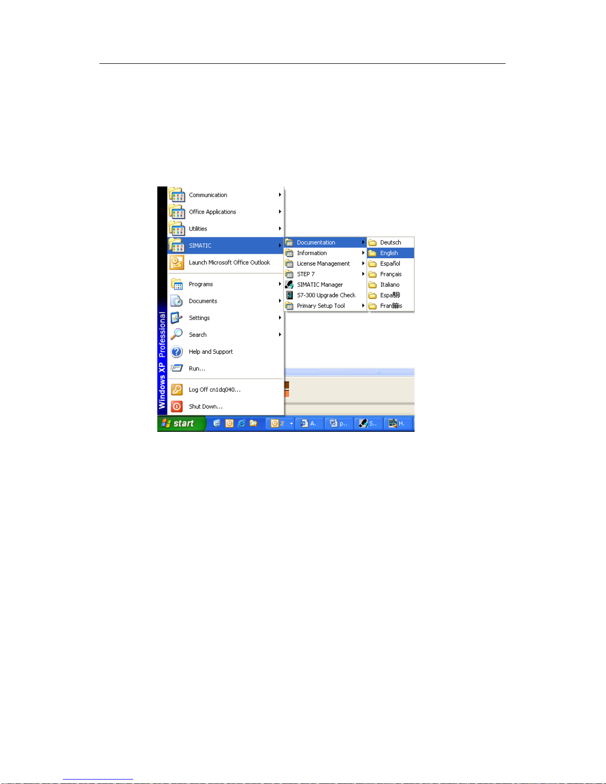
After all drive programs are installed, user may search for all CP module manuals
from the computer, whose detailed position is "Start-> SIMATIC-> Documentation -
> English”, or they may be found directly from the folder of STEP7 installation
path“… Program files-> Siemens -> Step7 -> S7MANUAL -> S7PtP_Cp”.
Fig. 1: Module manual path diagram
Page 7
4 ASCII protocol communication
CP340/CP341/CP440/CP441 Communication and Programming
Entry-ID: 88867653, V1.0, 02/2014
7
Siemens AG 2014 All rights reserved
4 ASCII protocol communication
The communication mode in ASCII protocol is used to realize serial communication
of user-defined protocol, and it is applicable to communication with the intelligent
instrument, bar-code reader, scanner, and printer, etc. that support serial
communication.
The following examples are used to introduce the ASCII protocol communication of
Siemens serial communication modules CP340, CP341, CP440 and CP441.
4.1 ASCII protocol communication of CP340
4.1.1 Hardware catalog
PS 307
6ES7 307-1EA00-0AA0
CPU 315-2DP
6ES7 315-2AG10-0AB0
MMC
6ES7 953-8LG11-0AA0
CP340
6ES7 340-1AH01-0AE0
4.1.2 Configuration
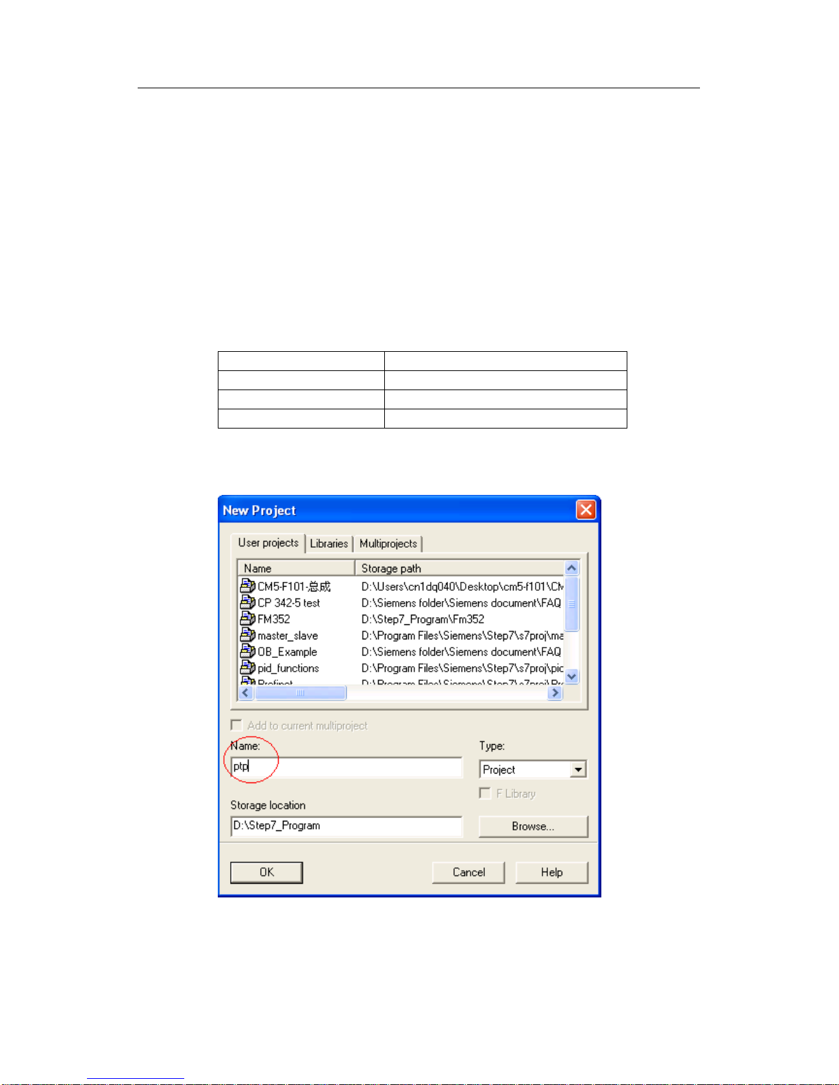
1. Open STEP 7,and click File->New...to create a new project in name of ptp.
Fig. 2: Dialog box of New project
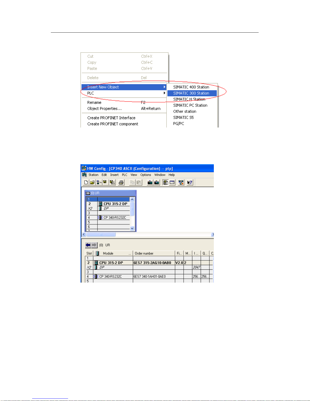
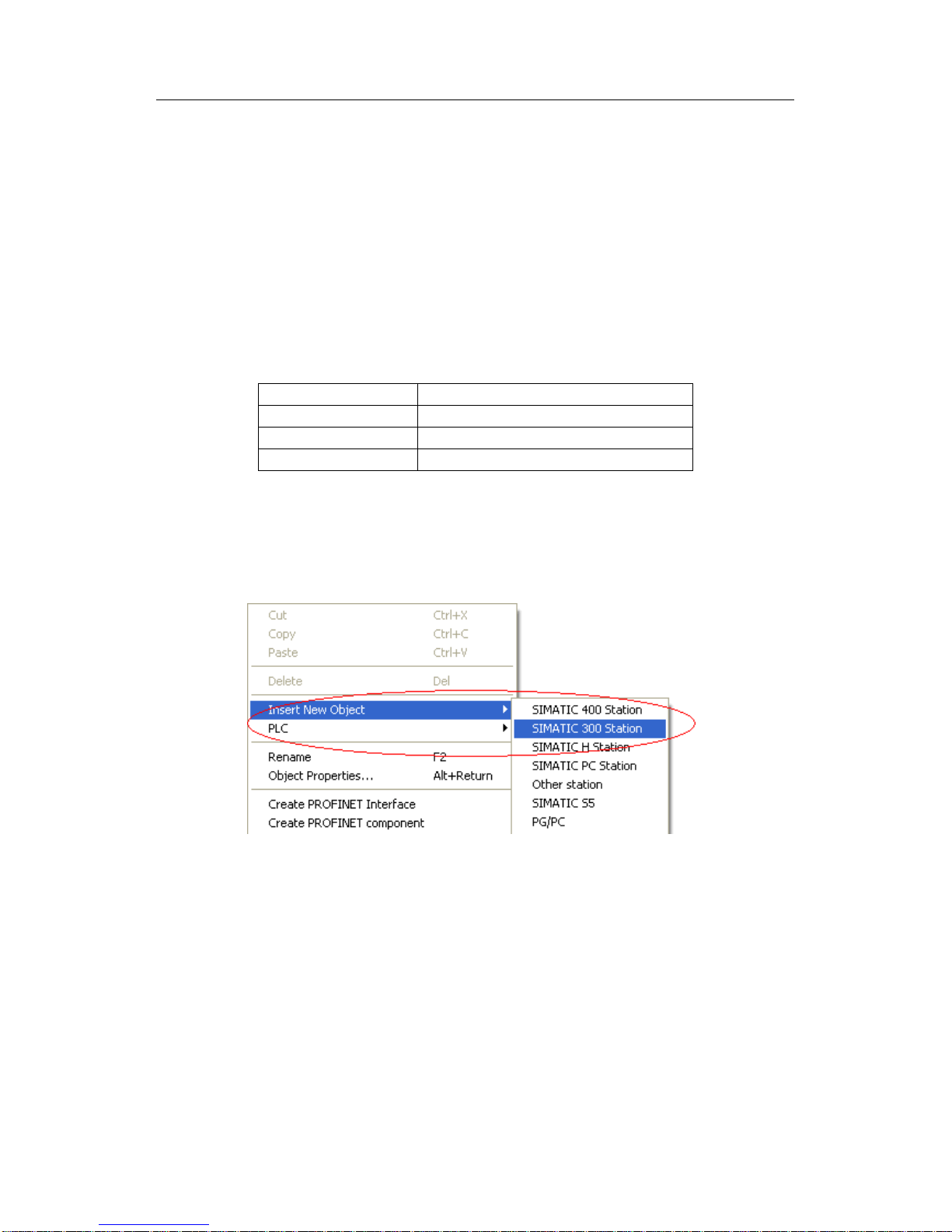
2. Right-click the project name, select Insert New Object->SIMATIC 300 Station to
change the station name to CP340 ASCII.
Page 8
4 ASCII protocol communication
CP340/CP341/CP440/CP441 Communication and Programming
Entry-ID: 88867653, V1.0, 02/2014
8
Siemens AG 2014 All rights reserved
Fig. 3: Insert S7-300 station
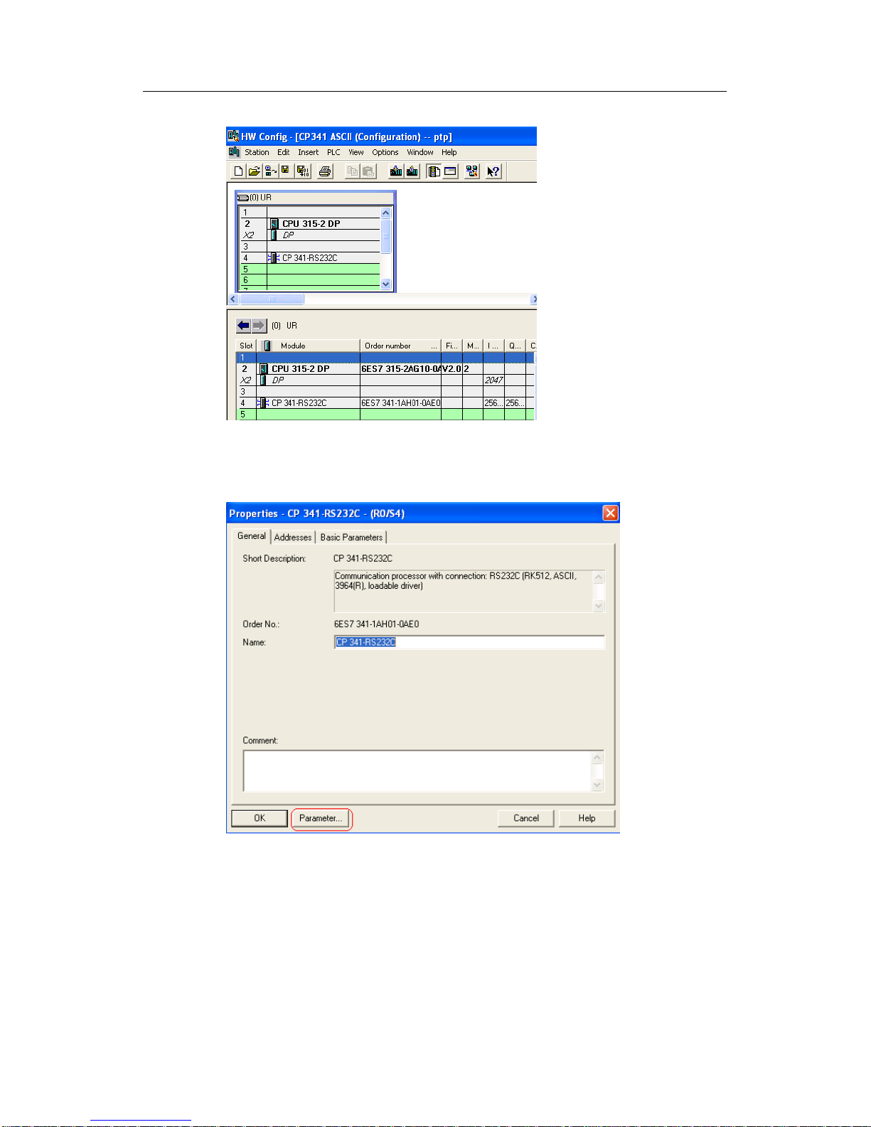
3. Double-click Hardware to enter the hardware configuration interface and insert
RACK, CPU315-2DP and CP340.
Fig. 4: Configuration hardware
Page 9
4 ASCII protocol communication
CP340/CP341/CP440/CP441 Communication and Programming
Entry-ID: 88867653, V1.0, 02/2014
9
Siemens AG 2014 All rights reserved
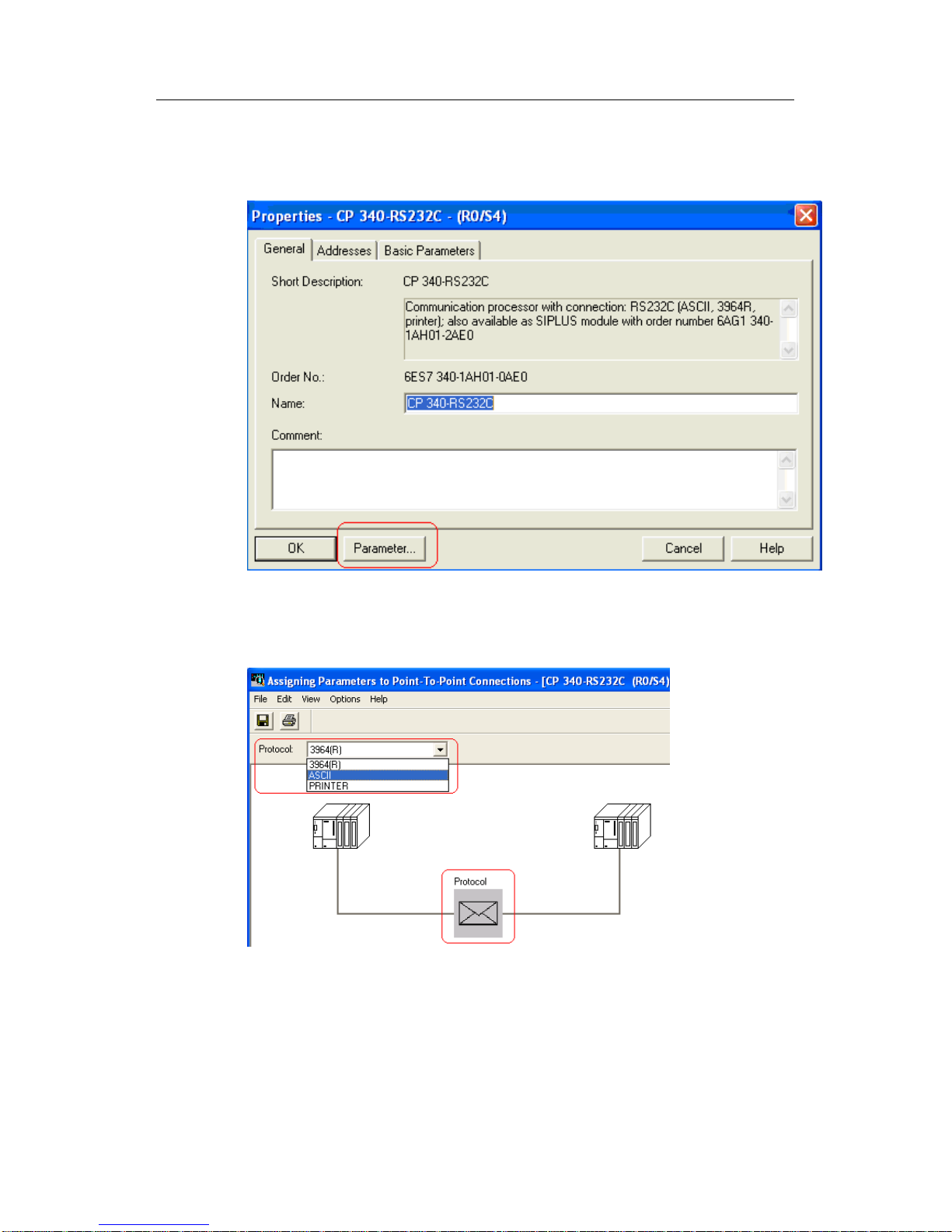
4. Double-click CP340 module, and click Parameter... to configure CP340
parameters.
Fig. 5: CP340 Properties dialog box
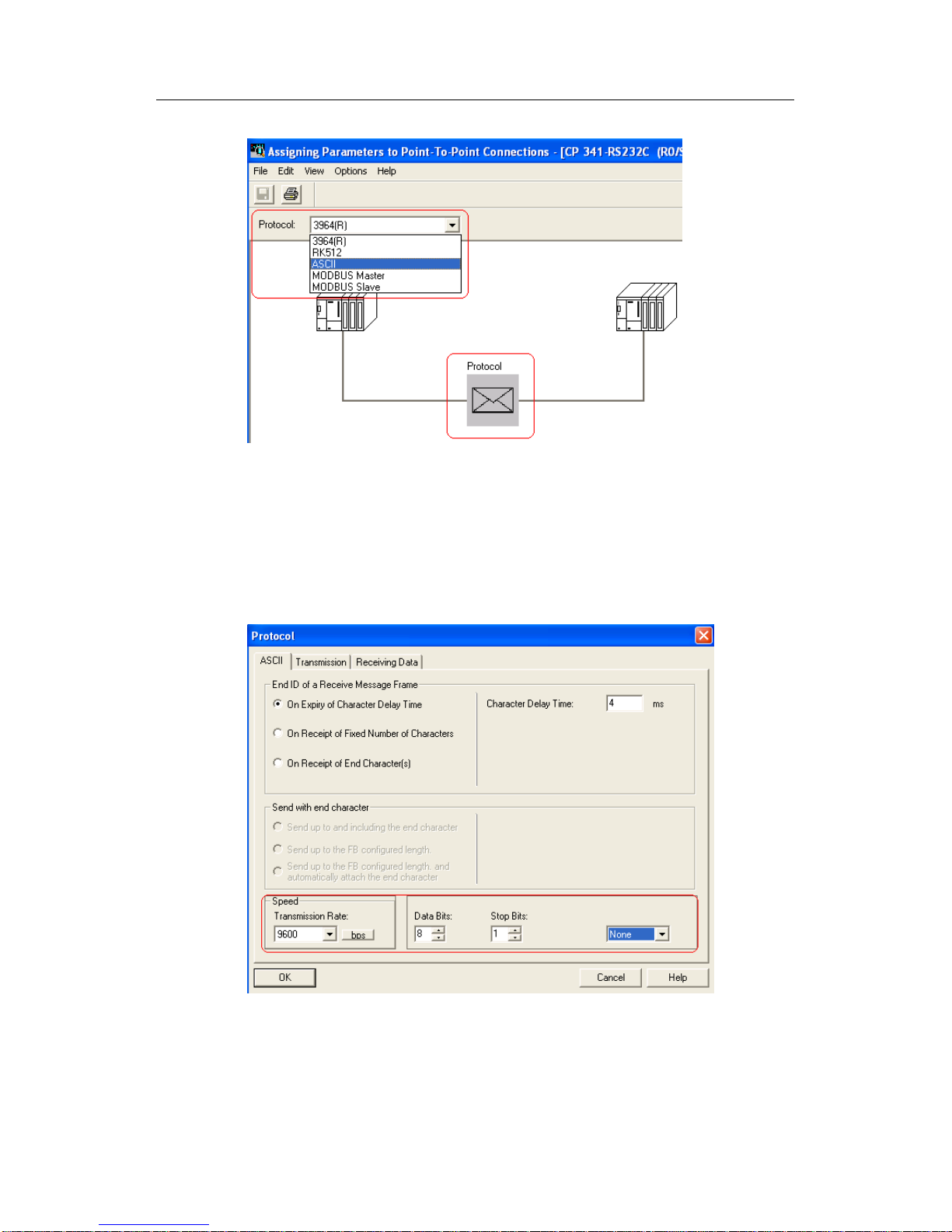
5. Select ASCII from Protocol options.
Fig. 6: Protocol selection
Page 10
4 ASCII protocol communication
CP340/CP341/CP440/CP441 Communication and Programming
Entry-ID: 88867653, V1.0, 02/2014
10
Siemens AG 2014 All rights reserved
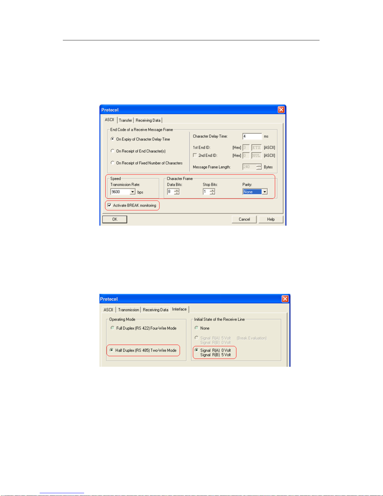
6. Double-click the envelop icon under Protocol to configure ASCII communication
parameters. The set communication parameters shall be the same as those of the
communication partner. Communication Baud rate: 9600bps,Data bit: 8 bits,
Stop bit: 1 bit, Parity: none, Character delay time: 4ms, Other parameters shall be
in default settings.
Fig. 7: Distributing communication parameters for ASCII protocol
As shown in the Fig. above, if "Activate BREAK monitoring" is selected, the SF red
indicator of CP340 will be on when RS232C cable is not connected or the serial
port of the communication partner is not activated.
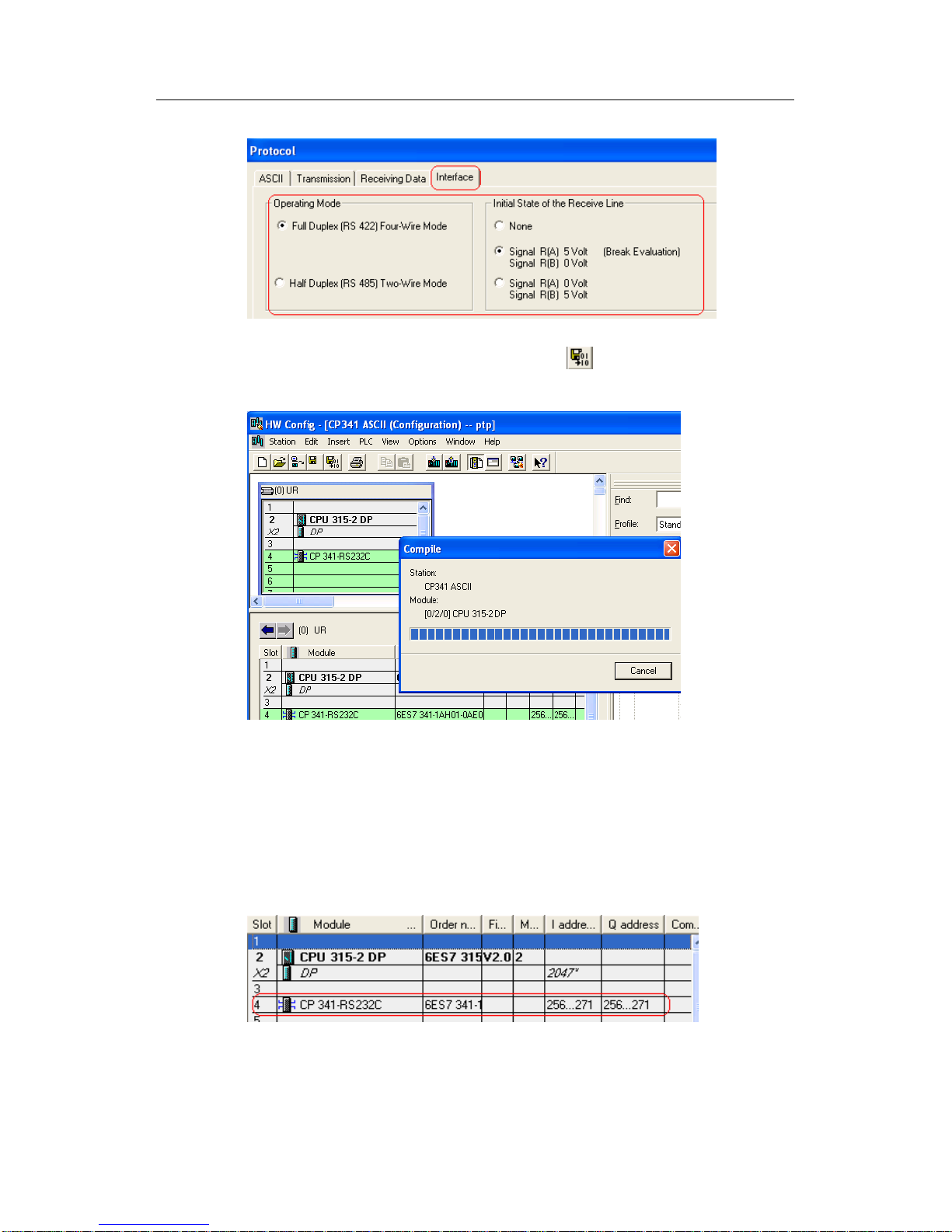
7. If CP340 in RS422/485 interface is selected, the interface properties shall also
be set, as shown below:
Fig. 8: Configuration interface parameters
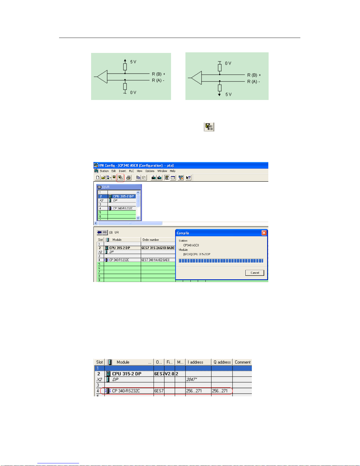
When the interface is in RS485 type (half-duplex mode), the initial state of the
receive side will be R(A)0V/R(B)5V, and it will not support wire-break detection
function. When the interface is in RS422 type (full-duplex mode) and the initial
state of the receive side is set as R(A)0V/R(B)5V, it will support wire-break
detection function. These 2 states correspond to the following interface pins of the
communication partner receive side:
Page 11
4 ASCII protocol communication
CP340/CP341/CP440/CP441 Communication and Programming
Entry-ID: 88867653, V1.0, 02/2014
11
Siemens AG 2014 All rights reserved
Fig. 9: Wiring of receiver at interface RS485/422
8. After the parameters are configured, click button to save and compile the
hardware configurations. After it is confirmed that no error exists, download the
hardware configurations to CPU to complete the whole hardware configuration
process.
Fig. 10: Compile and save hardware configuration
4.1.3 Write communication program
1. Double-click OB1 to open OB1 programming screen. Invoke Send Function
Block FB3 P_SEND from Libraries -> CP PtP -> CP340 and distribute instance
data block DB3 to it. Set the block parameter LADDR as the start logic address 256
for module CP340 in hardware configuration.
Fig. 11: Logic address of CP340
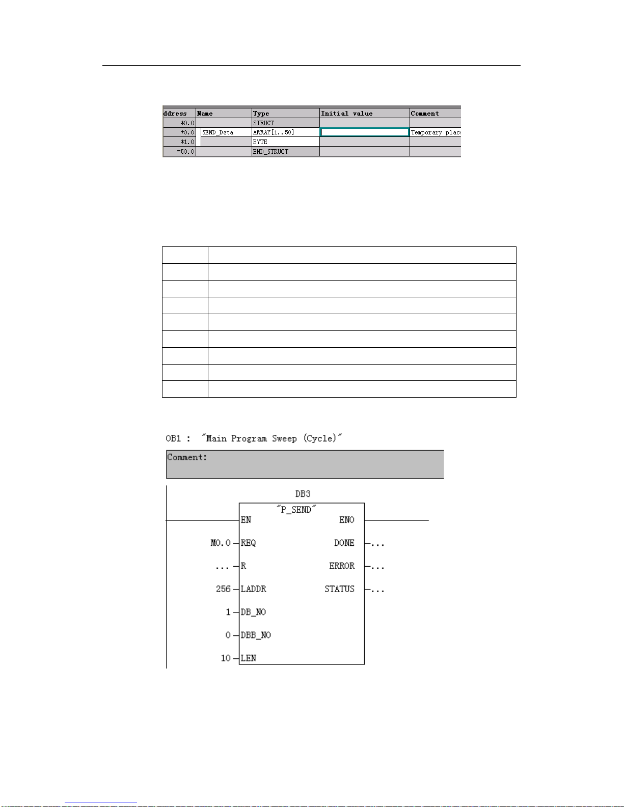
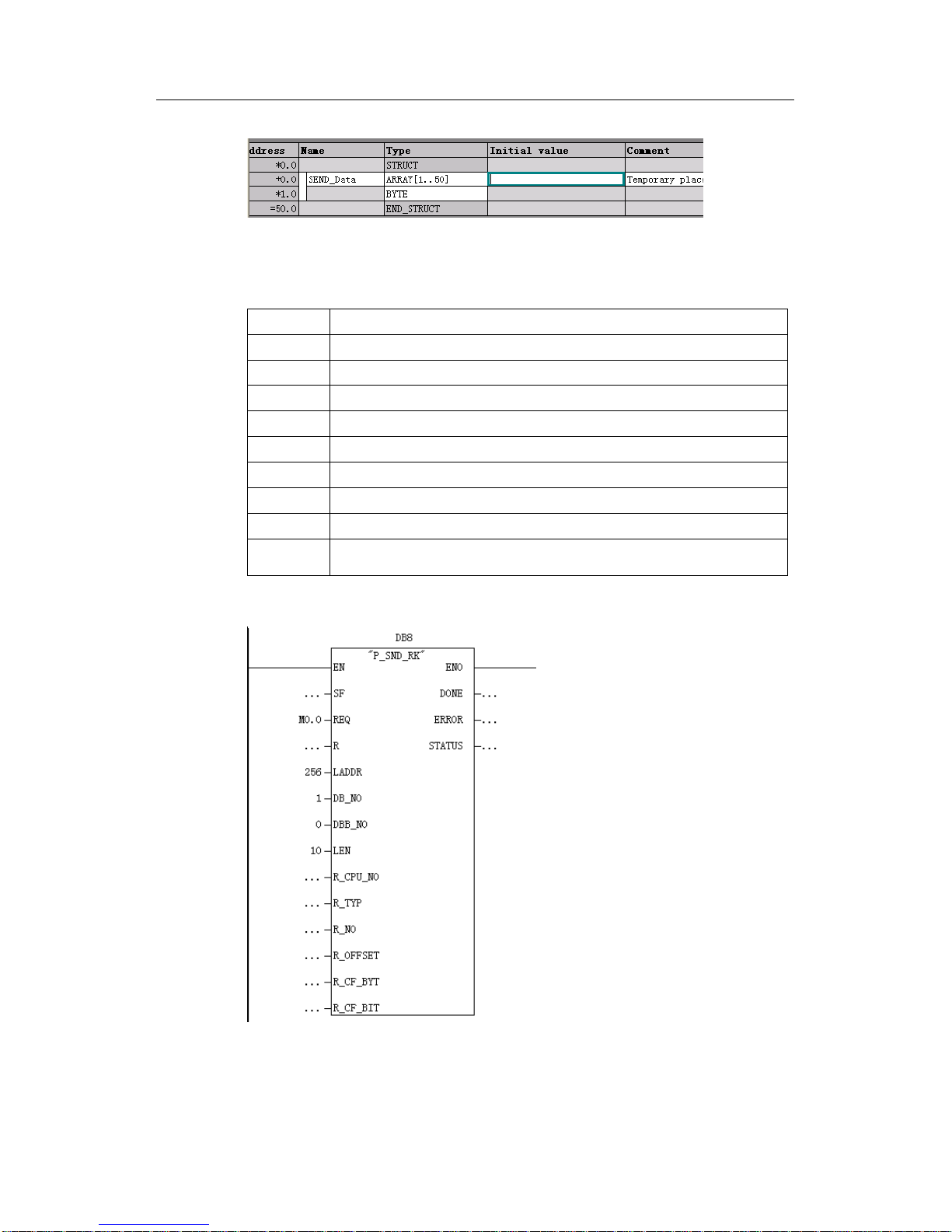
2. Create Send Data block DB1.
R(A)0V/R(B)5V
R(A)5V/R(B)0V
Page 12
4 ASCII protocol communication
CP340/CP341/CP440/CP441 Communication and Programming
Entry-ID: 88867653, V1.0, 02/2014
12
Siemens AG 2014 All rights reserved
Fig. 12: Send Data block DB1
3. Invoke Send Function block
The parameters of the send function block FB3 P_SEND of CP340 are set as in
the table below:
LADDR
Start logic address in hardware configuration, which is 256 in this example
DB_NO
Send Data block number, which is 1(DB1) in this example
DBB_NO
Start address of Send Data, which is 0(DB1.DBB0) in this example
LEN
Length of send data, which is 10 in this example
REQ
trigger bit of Send Data, rising edge trigger, which is M0.0 in this example
R
Cancel communication, which is not available in this example
DONE
send complete bit, which is TRUE if Send completes and has no error
ERROR
error bit, TRUE indicating that it has an error
STATUS
Status word, ID error code. See CP340 manual for related descriptions
Table 3: Parameter definition of FB3 P_SEND
Fig. 13: Invoke FB3 P_SEND from OB1
4. Invoke Receive Function Block FB2 P_RCV from Libraries -> CP PtP -> CP340
and distribute instance data block DB2 to it. Set LADDR as the start logic address
256.
Page 13

4 ASCII protocol communication
CP340/CP341/CP440/CP441 Communication and Programming
Entry-ID: 88867653, V1.0, 02/2014
13
Siemens AG 2014 All rights reserved
5. Create receive data block DB10.
Fig. 14: Receive data block DB10
6. Invoke receive function block
The parameters of the receive function block FB2 P_RCV of CP340 are set as in
the table below:
LADDR
Start logic address in hardware configuration, which is 256 in this example
DB_NO
Send Data block number, which is 10(DB10) in this example
DBB_NO
Start address of Send Data, which is 0(DB10.DBB0) in this example
LEN
Length of receive data, which is MW2 in this example. This value is not 0 only
in the current cycle when data are received. The length of received data may
be determined by checking the MW4 value.
EN_R
Enable receive bit, which is M0.1 in this example.
R
Cancel communication, which is not available in this example
NDR
Receive complete bit, which is TRUE if Receive completes and has no error
ERROR
error bit, TRUE indicating that it has an error
STATUS
status word, ID error code. See CP340 manual for related descriptions
Table 4: Parameter definition of FB2 P_RCV
Fig. 15: Invoke FB2 P_SEND from OB1
Page 14
4 ASCII protocol communication
CP340/CP341/CP440/CP441 Communication and Programming
Entry-ID: 88867653, V1.0, 02/2014
14
Siemens AG 2014 All rights reserved
4.1.4 Equipment connection
Use standard RS232C cable to connect serial ports of CP340 and computer. The
detailed cable connecting method may be seen in CP340 Manual - Chapter B:
Connecting cables.
4.2 ASCII protocol communication of CP341
4.2.1 Hardware catalog
PS 307
6ES7 307-1EA00-0AA0
CPU 315-2DP
6ES7 315-2AG10-0AB0
MMC
6ES7 953-8LG11-0AA0
CP341
6ES7 341-1AH01-0AE0
4.2.2 Configuration
1. Open the project ptp created above, and right-click the project name, select
Insert New Object->SIMATIC 300 Station to change the station name to CP341
ASCII.
Fig. 19: Insert S7-300 station
2. Double-click Hardware to enter the hardware configuration interface and insert
RACK, CPU315-2DP and CP341.
Page 15
4 ASCII protocol communication
CP340/CP341/CP440/CP441 Communication and Programming
Entry-ID: 88867653, V1.0, 02/2014
15
Siemens AG 2014 All rights reserved
Fig. 20: Configuration hardware
3. Double-click CP341 module, and click Parameter... to configure CP341
parameters.
Fig. 21: CP341 Properties dialog box
4. Select ASCII protocol from Protocol options.
Page 16
4 ASCII protocol communication
CP340/CP341/CP440/CP441 Communication and Programming
Entry-ID: 88867653, V1.0, 02/2014
16
Siemens AG 2014 All rights reserved
Fig. 22: Protocol selection
5. Double-click the envelop icon under Protocol to configure ASCII communication
parameters. The set communication parameters shall be the same as those of the
communication partner. Communication Baud rate:9600bps,Data bit: 8 bits, Stop
bit: 1 bit, Parity: none, Character delay time:4ms,Other parameters shall be in
default settings.
Fig. 23: Distributing parameters for ASCII protocol
6. If CP341 in RS422/485 interface is selected, the interface properties shall also
be set, as shown in the Fig. below. Refer to the text above for initial state of receive
side.
Page 17
4 ASCII protocol communication
CP340/CP341/CP440/CP441 Communication and Programming
Entry-ID: 88867653, V1.0, 02/2014
17
Siemens AG 2014 All rights reserved
Fig. 24: Configuration interface parameters
7. After completing configuration, user may click button to save and compile
the hardware configuration and download it to CPU after confirming that no error
exists. The whole hardware configuration process is completed by now.
Fig. 25: Compile and save hardware configuration
4.2.3 Write communication program
1. Double-click OB1 to open OB1 programming screen. Invoke Send Function
Block FB8 P_SND_RK from Libraries -> CP PtP -> CP341 and distribute instance
data block DB8 to it. Set the parameter LADDR as the start logic address 256 for
module CP340 in hardware configuration.
Fig. 26: Logic address of CP341
2. Create Send Data block DB1.
Page 18
4 ASCII protocol communication
CP340/CP341/CP440/CP441 Communication and Programming
Entry-ID: 88867653, V1.0, 02/2014
18
Siemens AG 2014 All rights reserved
Fig. 27: Send Data block DB1
3. Invoke Send Function block
The parameters of the send function block FB8 P_SND_RK of CP341 are set as in
the table below:
LADDR
Start logic address in hardware configuration, which is 256 in this example
DB_NO
Send Data block number, which is 1(DB1) in this example
DBB_NO
Start address of Send Data, which is 0(DB1.DBB0) in this example
LEN
Length of send data, which is 10 in this example
REQ
trigger bit of Send Data, rising edge trigger, which is M0.0 in this example
R
Cancel communication
DONE
send complete bit, which is TRUE if Send completes and has no error
ERROR
error bit, TRUE indicating that it has an error
STATUS
status word, ID error code. See CP341 manual for related descriptions
Other
parameters
Irrelevant to ASCII communication protocol, and not available in this
example
Table 5: Parameter definition of FB8 P_SND_RK
Fig. 28: Invoke FB8 P_SND_RK from OB1
Page 19
4 ASCII protocol communication
CP340/CP341/CP440/CP441 Communication and Programming
Entry-ID: 88867653, V1.0, 02/2014
19
Siemens AG 2014 All rights reserved
4. Invoke Receive Function Block FB7 P_RCV_RK from Libraries -> CP PtP ->
CP341 and distribute instance data block DB7 to it. Set LADDR as the start
logic address 256 in hardware configuration.
5. Create receive data block DB10
Fig. 29: Receive data block DB10
6. Invoke receive function block
The parameters of the receive function block FB8 FB7 P_RCV_RK of CP341
are set as in the table below:
LADDR
Start logic address in hardware configuration, which is
256 in this example
DB_NO
Send Data block number, which is 10(DB10) in this
example
DBB_NO
Start address of Send Data, which is 0(DB10.DBB0) in
this example
LEN
Length of receive data, which is MW2 in this example.
This value is not 0 only in the current cycle when data are
received. The length of received data may be determined
by checking the MW4 value.
EN_R
Enable receive bit, which is M0.1 in this example.
R
Cancel communication, which is not available in this
example
NDR
Receive complete bit, which is TRUE if Receive
completes and has no error
ERROR
error bit, TRUE indicating that it has an error
STATUS
status word, ID error code. See CP341 manual for related
descriptions
Other
parameters
Irrelevant to ASCII communication protocol, and not
available in this example
Table 6: Parameter definition of FB7 P_RCV_RK
Page 20
4 ASCII protocol communication
CP340/CP341/CP440/CP441 Communication and Programming
Entry-ID: 88867653, V1.0, 02/2014
20
Siemens AG 2014 All rights reserved
Fig. 30: Invoke FB7 P_RCV_RK from OB1
4.2.4 Equipment connection
Use standard RS232C cable to connect serial ports of CP341 and computer. The
detailed cable connecting method may be seen in CP341 Manual - Chapter B:
Connecting cables.
4.3 ASCII protocol communication of CP440
4.3.1 Hardware catalog
RACK-400
6ES7 400-1JA01-0AA0
PS407
6ES7 407-0KA02-0AA0
CPU
6ES7 414-3XJ04-0AB0
CP440
6ES7 440-1CS00-0YE0
4.3.2 Configuration
1. Open the project ptp that has been created, and right-click the project name,
select Insert a new SIMATIC 400 Station to change the station name to CP440
ASCII.
Page 21
4 ASCII protocol communication
CP340/CP341/CP440/CP441 Communication and Programming
Entry-ID: 88867653, V1.0, 02/2014
21
Siemens AG 2014 All rights reserved
Fig. 34: Insert S7-400 station
2. Double-click Hardware to enter the hardware configuration screen and insert
RACK-400,PS407,CPU414-3DP and CP440.
Fig. 35: Configuration hardware
3. Double-click CP440 module and click Parameter to configure CP440
parameters, and select ASCII protocol in Protocol options.
Page 22

4 ASCII protocol communication
CP340/CP341/CP440/CP441 Communication and Programming
Entry-ID: 88867653, V1.0, 02/2014
22
Siemens AG 2014 All rights reserved
Fig. 36: Protocol selection
4. Double-click the envelop icon in Protocol to configure the performance
parameters in it. The set communication parameters must match those of the
communication partner. Baud rate: 9600bps,Data bit: 8 bits,,Stop bit: 1 bit,
Parity: none, Character delay time:4ms,other parameters may use default data.
Fig. 37: Distributing parameters for ASCII protocol
5. As CP440 has only one type of RS422/485 interface, conversion equipment
shall be required if it has different interface from the communication partner, and all
other parameters shall be the same as CP340/341 when in ASCII communication.
Page 23

4 ASCII protocol communication
CP340/CP341/CP440/CP441 Communication and Programming
Entry-ID: 88867653, V1.0, 02/2014
23
Siemens AG 2014 All rights reserved
Fig. 38: Configuration interface parameters
6. After configuration completes, compile and save the hardware configuration,
and download it after it is confirmed correct.
4.3.3 Write communication program
1. Double-click OB1 to open programming screen. Invoke Send Function Block
FB10 SEND_400 from Libraries->CP PtP->CP440 and distribute instance data
block DB10 to it. Set the parameter LADDR as the start logic address 512 in
hardware configuration.
Fig. 39: Logic address of CP440
2. Create a Send Data block DB1
Fig. 40: Send Data block DB1
3. Invoke Send Data block
The parameters of the send function block FB10 SEND_400 of CP440 are set as in
the table below:
Name
Data
comments
Page 24

4 ASCII protocol communication
CP340/CP341/CP440/CP441 Communication and Programming
Entry-ID: 88867653, V1.0, 02/2014
24
Siemens AG 2014 All rights reserved
type
REQ
BOOL
Send Data trigger bit, rising edge
trigger, which is M0.0 in this
example
R
BOOL
Cancel send, discontinue
communication
LADDR
INT
Module start logic address in
hardware configuration, which is
512 in this example
DB_NO
INT
Send Data block number, which
is 1(DB1) in this example
DBB_NO
INT
Start address of Send Data,
which is 0(DB1.DBB0) in this
example
LEN
INT
Length of send data, which is 15
in this example
DONE
BOOL
send complete bit, which is TRUE
if Send completes and has no
error
ERROR
BOOL
error bit, which is TRUE if send
has error
STATUS
WORD
status word indicating error code.
If ERROR = 1, this status word
includes error information, and
user may check implication of the
information code online or obtain
the related instruction from
CP440 manual.
Table 7: Parameter definition of FB10 SEND_440
Page 25

4 ASCII protocol communication
CP340/CP341/CP440/CP441 Communication and Programming
Entry-ID: 88867653, V1.0, 02/2014
25
Siemens AG 2014 All rights reserved
Fig. 41: Invoke FB10 SEND_440 from OB1
4. Invoke receive function block FB9 RECV_440 from the same folder in the library
and distribute instance data block DB9 to it, and set LADDR as input start logic
address 512 in hardware configuration.
5. Create receive data block DB2
6. Invoke receive function block
The parameters of the receive function block FB9 RECV_CP440 are set as in the
table below:
Name
Type
Data
format
comments
EN_R
Input
BOOL
Enable receive bit, which is M1.0 in this example.
R
Input
BOOL
Cancel communication and give up receive
LADDR
Input
INT
Module start logic address in hardware
configuration, which is 512 in this example
DB_NO
Input
INT
Receive Data block number, which is 2(DB2) in
this example
DBB_NO
Input
INT
Start address of Receive Data, which is
0(DB2.DBB0) in this example
NDR
Output
BOOL
Receive complete bit, which is TRUE if Receive
completes and has no error
ERROR
Output
BOOL
error bit, which is TRUE if receive has error
LEN
Output
INT
Length (in byte) of receive data, which is not 0 only
in the current cycle when data are received.
STATUS
Output
WORD
status word indicating error code. If ERROR = 1,
this status word includes error information, and
user may check implication of the information code
online or obtain the related instruction from CP440
manual.
Table 8: Parameter definition of FB9 RECV_440
Fig. 42: Invoke FB9 RECV_440 from OB1
Page 26

4 ASCII protocol communication
CP340/CP341/CP440/CP441 Communication and Programming
Entry-ID: 88867653, V1.0, 02/2014
26
Siemens AG 2014 All rights reserved
4.3.4 Equipment connection
CP440 module only provides one 15-pin RS422/485 serial port. Select RS422 or
RS485 interface according to the wiring mode. Only one interface is valid. RS422
is 4-wire and in full-duplex mode while RS485 is 2-wire and in half-duplex mode.
The detailed cable connecting method may be seen in CP440 Manual - Appendix
B: Connecting cables.
4.4 ASCII protocol communication of CP441
CP441 communication module may select sub-module in different interface type
according to the actual application in order to realize communication with one or
more communication partners. CP441-1 (1 selectable sub-module interface),
CP441-2 (2 selectable sub-module interfaces). The sub-module interfaces are in 3
types:
Order number
Interface type
comments
6ES7963-1AA00-0AA0
RS232C
9-pin D type connection
6ES7963-2AA00-0AA0
20mA TTY
9-pin D type connection
6ES7963-3AA00-0AA0
RS422/485
15-pin D type connection
Table 9: CP441 interface sub-module
The configuration process is introduced below with CP441-2 as an example.
4.4.1 Hardware catalog
RACK-400
6ES7 400-1JA01-0AA0
PS407
6ES7 407-0KA02-0AA0
CPU
6ES7 414-3XJ04-0AB0
CP441-2
6ES7 441-2AA03-0AE0
(Interface1:RS232C, interface used in this example)
(Interface2:RS422/485)
Page 27

4 ASCII protocol communication
CP340/CP341/CP440/CP441 Communication and Programming
Entry-ID: 88867653, V1.0, 02/2014
27
Siemens AG 2014 All rights reserved
4.4.2 Configuration
1. Open the project ptp that has been created, and insert a new SIMATIC 400
Station to change the station name to CP441 ASCII. Double-click Hardware to
enter the hardware configuration screen, and insert the related module in steps
stated above.
Fig. 43: Configuration hardware
2. Double-click CP441-2 module and click to enter Basic Parameters. Select
Interface address, and designate interface type of the sub-module. RS232C
interface is used in this example.
Page 28

4 ASCII protocol communication
CP340/CP341/CP440/CP441 Communication and Programming
Entry-ID: 88867653, V1.0, 02/2014
28
Siemens AG 2014 All rights reserved
Fig. 44: Setting of basic interface parameters
3. Click Parameter, and configure CP441-2 parameters.
Fig. 45: Protocol selection
4. Double-click the envelop icon under Protocol to configure ASCII communication
parameters. The set communication parameters shall be the same as those of the
communication partner, and the others shall be in default values. The specific
operations may be seen in the text above, which are not repeated here.
5. After completing configuration, return to Sub-module interface type selection
interface, and click General to enter Interface ->PtP 1 and create a new PtP
subnet, and then click OK to confirm.
Page 29

4 ASCII protocol communication
CP340/CP341/CP440/CP441 Communication and Programming
Entry-ID: 88867653, V1.0, 02/2014
29
Siemens AG 2014 All rights reserved
Fig. 46: Create new PtP network
PtP 1 interface is in connection status at this moment. PtP 2 has the same
configuration, which is not introduced for it is not used in this example.
Fig. 47: Interface status after PtP is connected
6. Then open the configure network icon in the hardware configuration
screen to enter the network configuration interface.
Click to select the CPU in this station, and user may see that communication
connection table appears under the page. Right-click the first line to insert new
connection, and the connection is in "point-to-point connection" type.
Page 30

4 ASCII protocol communication
CP340/CP341/CP440/CP441 Communication and Programming
Entry-ID: 88867653, V1.0, 02/2014
30
Siemens AG 2014 All rights reserved
Fig. 48: Insert a new connection
7. Select "Unspecified" as the connection object. This option is used for
connection with third-party devices and the devices without communication bus,
including S7-CP PtP (CP340,CP341), S5-CP PtP and Printer, etc. If the
communication partner is CP441, it shall be confirmed that it has been connected
to a same PtP subnet and selected directly as the connection object.
Fig. 49: Insert a new connection
Page 31

4 ASCII protocol communication
CP340/CP341/CP440/CP441 Communication and Programming
Entry-ID: 88867653, V1.0, 02/2014
31
Siemens AG 2014 All rights reserved
8. After completing configuration, click OK to confirm. PtP connection properties
screen will pop up at this moment.
Fig. 50: Configuration connection
One parameter Local ID (Hex) in this screen shall be noted for it will be used
when programming to invoke system function block. You may modify it in
manual way to fit the parameters in the program SFB that have been
configured, but its range shall be noted: W#16#1000---W#16#1400。
The "communication direction" may be selected according to the actual
demand. In this example, the third type is used: Two-way communication. Click
OK to confirm and compile the configuration, and download it after it is
confirmed correct.
9. Confirm the connection status online, and click as shown in the Fig.
below. It may be seen that "Connection status" is "set up", showing that the
connection has been created.
Fig. 51: Monitoring of connection status
Page 32

4 ASCII protocol communication
CP340/CP341/CP440/CP441 Communication and Programming
Entry-ID: 88867653, V1.0, 02/2014
32
Siemens AG 2014 All rights reserved
4.4.3 Write communication program
1. Double-click OB1 to open the programming screen. Invoke SFB12 BSEND from
Libraries-> Standard library-> System function blocks, and distribute instance
data block DB12 to it and create send data block DB1.
Fig. 52: Send Data block DB1
2. Invoke send function block. The SFB12 BSEND parameters are set as shown in
the table below:
Name
Data
type
comments
REQ
BOOL
send request bit, rising edge trigger, which is M0.0 in this
example
R
BOOL
Cancel communication
ID
WORD
Local ID number, which is obtained from the PtP connection
properties and is hexadecimal.
R_ID
DWORD
Distinguish double word, which may be any data. However, if the
program uses multiple BSEND blocks, different serial numbers
shall be distributed to them.
SD_1
ANY
Data send area. DB area is used in this example, and the send
data are in 5 bytes.
Other addresses and data types may also be used for access,
and the detailed information may be obtained from Step7 SFB12
online help.
LEN
WORD
Send data length, which is counted in bytes.
DONE
BOOL
Send complete bit, which is set as 1 if the task completes and has
no error.
ERROR
BOOL
Error bit, which is set as 1 in case of error.
STATUS
WORD
Status word, indicating error code. The specific information may
be seen in online diagnosis of module or from CP441 Manual Chapter 9: Diagnosis information
Table 10: Parameter definition of SFB12 BSEND
Page 33

4 ASCII protocol communication
CP340/CP341/CP440/CP441 Communication and Programming
Entry-ID: 88867653, V1.0, 02/2014
33
Siemens AG 2014 All rights reserved
Fig. 53: Invoke SFB12 BSEND from OB1
3. At the same time, invoke SFB13 BRCV to receive data, and distribute
instance data block DB13, and create a new DB block DB2 to receive data.
Fig. 54: Receive data block DB2
Name
Data type
comments
EN_R
BOOL
Receive enable bit, allowing receive when it is
1. M8.0 is used in this example.
ID
WORD
Local ID number, which is obtained from the
PtP connection properties and is hexadecimal.
R_ID
DWORD
W#16#0 must be used when in ASCII, 3964(R)
communication.
RD_1
ANY
Data receive area. DB2 is used in this example
to receive.
LEN
WORD
Receive data length memory area, in bytes
NDR
BOOL
Receive complete bit, which is TRUE if Receive
completes and has no error
ERROR
BOOL
error bit, 1 indicating that it has an error
STATUS
WORD
Status word, indicating error code. The specific
information may be seen in online diagnosis of
module or from CP441 Manual - Chapter 9:
Diagnosis information
Table 11: Parameter definition of SFB13 BRCV
Page 34

4 ASCII protocol communication
CP340/CP341/CP440/CP441 Communication and Programming
Entry-ID: 88867653, V1.0, 02/2014
34
Siemens AG 2014 All rights reserved
Fig. 55: Invoke SFB13 BRCV from OB1
4.4.4 Equipment connection
Use standard RS232C cable to connect serial ports of CP441-2 interface1 and
computer. The detailed cable connecting method may be seen in CP441 Manual Appendix B: Connecting cables.
Page 35

5 MODBUS RTU Protocol communication
CP340/CP341/CP440/CP441 Communication and Programming
Entry-ID: 88867653, V1.0, 02/2014
35
Siemens AG 2014 All rights reserved
5 MODBUS RTU Protocol communication
MODBUS RTU communication protocol is in master-slave mode. In the
transmission process, the master sends a request telegram actively to the slave,
and the slave returns an answer telegram. For details of MODBUS RTU protocol,
please refer to related MODBUS RTU files or manuals.
5.1 MODBUS Slave protocol communication of CP341
5.1.1 Hardware catalog
PS 307
6ES7 307-1EA00-0AA0
CPU 315-2DP
6ES7 315-2AG10-0AB0
MMC
6ES7 953-8LG11-0AA0
CP341
6ES7 341-1AH01-0AE0
Dongle
6ES7 870-1AB01-0YA0
Dongle's support is necessary when using CP341 for MODBUS Protocol
communication. Before it is used, install Dongle in the Dongle slot at the back of
the CP341 module. Dongle and CP341 before and after inserting Dongle are
shown as in the Fig. below:
Fig. 57: Before and after inserting Dongle
Page 36

5 MODBUS RTU Protocol communication
CP340/CP341/CP440/CP441 Communication and Programming
Entry-ID: 88867653, V1.0, 02/2014
36
Siemens AG 2014 All rights reserved
5.1.2 Configuration
1. Open the project ptp created above, and right-click the project name, select
Insert New Object->SIMATIC 300 Station to change the station name to CP341
Modbus-S.
Fig. 58: Insert S7-300 station
2. Double-click Hardware to enter the hardware configuration interface and insert
RACK, CPU315-2DP and CP341.
Fig. 59: Configuration hardware
3. Double-click CP341 module, and click Parameter... to configure CP341
parameters. Select MODBUS Slave from Protocol options.
Page 37

5 MODBUS RTU Protocol communication
CP340/CP341/CP440/CP441 Communication and Programming
Entry-ID: 88867653, V1.0, 02/2014
37
Siemens AG 2014 All rights reserved
Fig. 60: Selecting communication protocol
4. Double-click the envelop icon under Protocol to configure MODBUS Slave
parameter, and click MODBUS-Slave button.
Fig. 61: Configure MODBUS Slave communication parameter
Step 1: set MODBUS Slave address, which is set as 2 in this example
Step 2: set parameters of MODBUS Slave, such as Baud rate, stop bit and check
bit, etc.
Then configure the parameters represented by the function codes. For details, see
the four figures below.
5. FC01,05,15: status of read and forced output bit. The left side is info transfer
address, and the right side is corresponding PLC address area, viz. the left
addresses from 0 to 100 match MODBUS address area 00001 to 00101, and the
Step 1
Step 2
Page 38

5 MODBUS RTU Protocol communication
CP340/CP341/CP440/CP441 Communication and Programming
Entry-ID: 88867653, V1.0, 02/2014
38
Siemens AG 2014 All rights reserved
corresponding Siemens data area is M0.0-M12.4. 101 to 200 match the MODBUS
Address area 00102 to 00201, and the corresponding Siemens data area is Q0.0
to Q12.3. The slave addresses 201 to 300 and 301 to 400 match the Modbus
address areas 00202 to 00301 and 00302 to 00401, and the corresponding
Siemens data area is Timer, Counter.
Fig. 62: Distribution of MODBUS Slave addresses
6. FC02 reads input data status, and the address matching is as stated above.
Fig. 63: Distribution of MODBUS Slave addresses
7. FC03,06,16 configuration output register data area corresponds to Siemens
data area DB block.
Fig. 64: Distribution of MODBUS Slave addresses
8. FC04 configuration input register data area also corresponds to Siemens data
area DB block.
Page 39

5 MODBUS RTU Protocol communication
CP340/CP341/CP440/CP441 Communication and Programming
Entry-ID: 88867653, V1.0, 02/2014
39
Siemens AG 2014 All rights reserved
Fig. 65: Distribution of MODBUS Slave addresses
9. Setting limit values for writing parameters
Fig. 66: Write parameter limit values for MODBUS Slave
10. If CP341 in RS422/485 interface is selected, the interface type shall also be set
as shown in the Fig. below, and other parameters shall be in default settings.
Fig. 67: Interface parameter assignment of MODBUS Slave
11. After configuration completes, a prompt will ask you whether you load the driver
before it is saved.
Page 40

5 MODBUS RTU Protocol communication
CP340/CP341/CP440/CP441 Communication and Programming
Entry-ID: 88867653, V1.0, 02/2014
40
Siemens AG 2014 All rights reserved
Fig. 68: Dialog box prompting loading driver
12. At this moment it must be connected to the actual PLC. Click Yes to load the
driver. The CPU must be in STOP mode when in loading. After the driver is loaded,
STEP7 will prompt "Driver already exists" if you load it another time. After
configuration completes, click button to save and compile the hardware
configuration and confirm that it has no error.
Fig. 69: Compile and save hardware configuration
5.1.3 Write communication program
1. Add FB7 and FB8 into the program Blocks in such method: double-click OB1 to
open OB1 programming screen, invoke send program block FB8 and receive
program block FB7 from Libraries->CP PtP->CP341, and then delete them from
OB1 because these two function blocks will be used in MODBUS Slave
communication.
2. Invoke MODBUS Slave function block FB80 at Libraries->Modbus->Modbus >FB80. Distribute instance data block DB80, and set the parameter LADDR as
start logic address 256 in the hardware configuration.
Page 41

5 MODBUS RTU Protocol communication
CP340/CP341/CP440/CP441 Communication and Programming
Entry-ID: 88867653, V1.0, 02/2014
41
Siemens AG 2014 All rights reserved
Fig. 70: Logic address of CP341
3. Invoke MODBUS Slave function block
LADDR
Start logic address in hardware configuration,
which is 256 in this example
START_TIME
timeout initialization timer, which is T1 in this
example
START_TIME
timeout initialization time value, which is 1s in
this example
OB_MASK
I/O access error mask bit, which is M100.0 in
this example
CP_START
FB initialization enable bit, which is M100.1 in
this example
CP_START_FM
CP_START initialization rising edge bit, which is
M100.2 in this example
CP_START_NDR
write from CP operation bit, which is M100.3 in
this example
CP_START_OK
initialization succeed flag, which is M100.4 in
this example
CP_START_ERROR
initialization fail flag, which is M100.5 in this
example
ERROR_NR
error number, which is MW102 in this example
ERROR_INFO
error message, which is MW104 in this
example. Refer to Modbus Slave Manual Chapter 10
Table 12: Parameter definition of FB80
Page 42

5 MODBUS RTU Protocol communication
CP340/CP341/CP440/CP441 Communication and Programming
Entry-ID: 88867653, V1.0, 02/2014
42
Siemens AG 2014 All rights reserved
Fig. 71: Invoke FB80 from OB1
4. Create FC03,06,16 function code communication data block DB1.
Fig. 72: Communication data block DB1
5. Create FC04 function code communication data block DB2.
Fig. 73: Communication data block DB2
5.1.4 Equipment connection
Use standard RS232C cable to connect serial ports of CP341 and computer.
The detailed cable connecting method may be seen in CP341 Manual Chapter B: Connecting cables.
5.1.5 Communication test
1. Download hardware configuration and program into CPU315-2DP firstly. Open
MODBUS master emulation software Modscan32 in the computer.
Page 43

5 MODBUS RTU Protocol communication
CP340/CP341/CP440/CP441 Communication and Programming
Entry-ID: 88867653, V1.0, 02/2014
43
Siemens AG 2014 All rights reserved
Fig. 74: Open Modscan32 software
2. Click Connection->Connect in Modscan32, as shown in the screen below.
Select COM port COM1 connecting the computer with CP341, and set the Baud
rate, data bit, stop bit and check mode, as shown in the Fig. below:
Fig. 75: Setting of Modscan32 communication parameter
3. After setting completes, click OK, and the following screen will be shown.
Page 44

5 MODBUS RTU Protocol communication
CP340/CP341/CP440/CP441 Communication and Programming
Entry-ID: 88867653, V1.0, 02/2014
44
Siemens AG 2014 All rights reserved
Fig. 76: Modscan32 operation interface
4. The 10 address data of the data display area correspond to the numeric values
(1-10 for DBW0 - DBW10 respectively)of the first 10 words of DB1 in CPU, as
shown in the Fig. below.
Fig. 77: DB1 data monitor
5. It is only necessary to change the accessed data type in order to read other
data, which is not introduced here.
6. For display of floating point number, it shall be explained that the high 16 bits
and low 16 bits of the floating point number in PLC are opposite to those displayed
in Modscan32, or in other words, the high 16 bits of the floating point number in
PLC correspond to the low 16 bits of the floating point number displayed in
Modscan32, and the low 16 bits of the floating point number in PLC correspond to
the high 16 bits of the floating point number displayed in Modscan32, which may
be handled in the program, as shown in the Fig. below:
Set data display method
Modbus slave
address
Modbus initial
address and length
Type of data accessed by
Modbus
Data display area
Page 45

5 MODBUS RTU Protocol communication
CP340/CP341/CP440/CP441 Communication and Programming
Entry-ID: 88867653, V1.0, 02/2014
45
Siemens AG 2014 All rights reserved
Fig. 78: Floating point number data processing
At this moment, the floating point number 40001 displayed in Modscan32
corresponds to the floating point number value of MD200, but MODBUS address
corresponds to DB1.DBD0.
Fig. 79: Floating point number data exchange
If CP341 module with RS422/RS485 interface is used, RS422/485 converter shall
be used when using computer serial port debugging program.
5.2 MODBUS Master protocol communication of CP341
5.2.1 Hardware catalog
PS 307
6ES7 307-1EA00-0AA0
CPU 315-2DP
6ES7 315-2AG10-0AB0
MMC
6ES7 953-8LG11-0AA0
CP341
6ES7 341-1AH01-0AE0
Dongle
6ES7 870-1AA01-0YA0
Insert Dongle into CP341, and the Dongle and CP341 before and after Dongle is
inserted are shown in the Fig. below:
Page 46

5 MODBUS RTU Protocol communication
CP340/CP341/CP440/CP441 Communication and Programming
Entry-ID: 88867653, V1.0, 02/2014
46
Siemens AG 2014 All rights reserved
Fig. 80: Before and after inserting Dongle
5.2.2 Configuration
1. Open the project ptp created above, and right-click the project name, select
Insert New Object->SIMATIC 300 Station to change the station name to CP341
Modbus-M.
Fig. 81: Insert S7-300 station
2. Double-click Hardware to enter the hardware configuration interface and insert
RACK, CPU315-2DP and CP341.
Page 47

5 MODBUS RTU Protocol communication
CP340/CP341/CP440/CP441 Communication and Programming
Entry-ID: 88867653, V1.0, 02/2014
47
Siemens AG 2014 All rights reserved
Fig. 82: Configuration hardware
3. Double-click CP341 module, and click Parameter... to configure CP341
parameters. Select MODBUS Master from Protocol options.
Fig. 83: Selecting communication protocol
4. Double-click the envelop icon under Protocol to configure Modbus Master
parameter, and click Modbus-Master button to set communication Baud rate,
etc.
Page 48

5 MODBUS RTU Protocol communication
CP340/CP341/CP440/CP441 Communication and Programming
Entry-ID: 88867653, V1.0, 02/2014
48
Siemens AG 2014 All rights reserved
Fig. 84: Configure MODBUS Master communication parameter
5. After configuration completes, a prompt will ask you whether you load the
driver before it is saved.
Fig. 85: Dialog box prompting loading driver
6. At this moment, it must be connected to the actual PLC. Click Yes to load
the driver or click Load Drivers. The CPU must be in STOP mode when in
loading.
Fig. 86: Load drivers
After the driver is loaded, STEP7 will prompt "Driver already exists" if you load
it another time. After configuration completes, click button to save and
compile the hardware configuration and confirm that it has no error.
Page 49

5 MODBUS RTU Protocol communication
CP340/CP341/CP440/CP441 Communication and Programming
Entry-ID: 88867653, V1.0, 02/2014
49
Siemens AG 2014 All rights reserved
Fig. 87: Compile and save hardware configuration
5.2.3 Write communication program
1. Double-click OB1 to open OB1 programming screen. Invoke send program
block FB8 P_SND_RK from Libraries -> CP PtP -> CP341 and distribute instance
data block DB8 to it. Set the parameter LADDR as the input start logic address 256
in hardware configuration.
Fig. 88: Logic address of CP341
2. Create send data block DB1, in which the slave address is 2, the function code
is 3 and start address is 0. Read 4 register data. For use of the function code 3,
see Modbus Master Manual - 5.3: Function Code 03 - Read Output Registers.
Fig. 89: Send Data block DB1
3. Invoke Send Function block
The FB8 P_SND_RK parameter setting may be seen in the table below:
SF
"S" means send, which must be in capital form here.
LADDR
Start logic address in hardware configuration, which is 256 in this
Page 50

5 MODBUS RTU Protocol communication
CP340/CP341/CP440/CP441 Communication and Programming
Entry-ID: 88867653, V1.0, 02/2014
50
Siemens AG 2014 All rights reserved
example
REQ
trigger bit of Send Data, rising edge trigger, which is M0.0 in this
example
DB_NO
Send Data block number, which is 1(DB1) in this example
DBB_NO
Start address of Send Data, which is 0(DB1.DBB0) in this example
LEN
Length of send data, which is 6 in this example
R_TYP
"X" refers to extended data block, which must be in capital form here.
R
Cancel communication, which is not available in this example
DONE
send complete bit, which is TRUE if Send completes and has no error
ERROR
error bit, TRUE indicating that it has an error
STATUS
Status word, ID error code. See Modbus Master Manual - Chapter 7 for
related description.
Other
parameters
Not applicable in this example.
Table 13: Parameter definition of FB8 P_SND_RK
Fig. 90: Invoke FB8 P_SND_RK from OB1
4. Invoke Receive Function Block FB7 P_RCV_RK from Libraries -> CP PtP ->
CP341 and distribute instance data block DB7 to it. Set LADDR as the input
start logic address 256 in hardware configuration.
Page 51

5 MODBUS RTU Protocol communication
CP340/CP341/CP440/CP441 Communication and Programming
Entry-ID: 88867653, V1.0, 02/2014
51
Siemens AG 2014 All rights reserved
Fig. 91: Logic address of CP341
5. Create receive data block DB2
Fig. 92:Receive data block DB2
6. Invoke receive function block
The FB7 P_RCV_RK parameter setting may be seen in the table below:
LADDR
Start logic address in hardware configuration, which is 256 in this
example
DB_NO
Send Data block number, which is 2(DB2) in this example
DBB_NO
Start address of Send Data, which is 0(DB2.DBB0) in this example
LEN
Length of receive data, which is MW4 in this example.This value is not
0 only in the current cycle when data are received. The length of
received data may be determined by checking the MW8 value.
EN_R
Enable receive bit, which is M0.3 in this example.
R
Cancel communication, which is not applicable in this example
NDR
Receive complete bit, which is TRUE if Receive completes and has no
error
ERROR
error bit, TRUE indicating that it has an error
STATUS
Status word, ID error code. See Modbus Master Manual - Chapter 7 for
related description.
Other
parameters
Not applicable in this example.
Table 14: Parameter definition of FB7 P_RCV_RK
Page 52

5 MODBUS RTU Protocol communication
CP340/CP341/CP440/CP441 Communication and Programming
Entry-ID: 88867653, V1.0, 02/2014
52
Siemens AG 2014 All rights reserved
Fig. 93: Invoke FB7 P_RCV_RK from OB1
5.2.4 Equipment connection
Use standard RS232C cable to connect serial ports of CP341 and computer. The
detailed cable connecting method may be seen in CP341 Manual - Chapter B:
Connecting cables.
5.2.5 Communication test
1. Install Modbus Slave test software. After installing, an icon will be
generated on the desktop. Double-click this icon to open Modbus Slave test
software, as shown in the Fig. below:
Page 53

5 MODBUS RTU Protocol communication
CP340/CP341/CP440/CP441 Communication and Programming
Entry-ID: 88867653, V1.0, 02/2014
53
Siemens AG 2014 All rights reserved
Fig. 94: Open Modbus Slave test software
2. Click the button Register Later. This software may be used for 30 days without
registration, but each time it may only be used for 15min. The software downloaded
from the Internet has no registration code. Then click the menu Connection>connect to configure the serial parameters, which shall be the same as the CP341
parameters.
Fig. 95: Setting communication parameters
3. Click OK, and then select the menu Setup->Slave Definition... to set the
communication data. As CP341 uses function code 3,03 Holding Register shall be
used. The address of the slave accessed by CP341 is 2, and Slave ID is set as 2.
The start address starts from 1. See the screen below:
Page 54

5 MODBUS RTU Protocol communication
CP340/CP341/CP440/CP441 Communication and Programming
Entry-ID: 88867653, V1.0, 02/2014
54
Siemens AG 2014 All rights reserved
Fig. 96: Setting communication parameters
4. Then set the address 1 to 4 as 111 to 444 respectively, set M0.3 as TRUE in
Step7 Variable table to enable receiving. Then set M0.0 as TRUE ( rising edge
trigger. If it is necessary to re-send, set M0.0 from TRUE to FALSE, and then set it
back to TRUE again). It may be monitored that the values from DB1.DBW0 to
DB1.DBW4 are 111 to 444, as shown in the Fig. below.
Fig. 97: Monitoring of receive data
5. If it is necessary to read the floating point number, it must be set in data format.
Click the menu Display->Float Inverse.
Fig. 98: Setting of floating point number data format
6. Set the values of address 1 and 3 as 1.234 and 5.678 respectively, and trigger
M0.0 to send. You may see that the received data are 1.234 and 5.678, as shown
in the Fig. below:
Page 55

5 MODBUS RTU Protocol communication
CP340/CP341/CP440/CP441 Communication and Programming
Entry-ID: 88867653, V1.0, 02/2014
55
Siemens AG 2014 All rights reserved
Fig. 99: Monitoring of receive data3
5.3 MODBUS Master protocol communication of CP441-2
5.3.1 Hardware catalog
RACK-400
6ES7400-1JA01-0AA0
PS407
6ES7407-0KA02-0AA0
CPU414-3
6ES7414-3XJ04-0AB0
CP441-2
6ES7441-2AA03-0AE0
Dongle
6ES7870-1AA01-0YA0
Dongle is installed in the same positions as S7-300 and CP341, and both are
behind the module. Refer to the pictures above.
5.3.2 Configuration
1. Open the created project ptp and insert a new SIMATIC 400 Station, and
change the station name to CP441-2 modbus Master. Double-click Hardware to
enter the hardware configuration screen, and insert RACK, PS, CPU and CP441-2.
The specific steps may be seen in the text above.
2. In the CP441-2 module, click Parameter to configure CP441-2 parameters, and
select MODBUS Master in Protocol options.
Page 56

5 MODBUS RTU Protocol communication
CP340/CP341/CP440/CP441 Communication and Programming
Entry-ID: 88867653, V1.0, 02/2014
56
Siemens AG 2014 All rights reserved
Fig. 100: Selecting communication protocol
3. Double-click the envelop icon under Protocol to configure Modbus Master
parameter, and click Modbus-master button to set the basic parameters such
as communication rate and message details, etc., and other parameters may
be in default settings.
Fig. 101: Configure MODBUS Master communication parameter
4. After completing configuration, click OK and save it, and close the dialog
box. Just as ASCII communication with CP441-2, create PtP connection for the
used interface, and record the Local ID (Hex) connection number.
Page 57

5 MODBUS RTU Protocol communication
CP340/CP341/CP440/CP441 Communication and Programming
Entry-ID: 88867653, V1.0, 02/2014
57
Siemens AG 2014 All rights reserved
Fig. 102: Configuration connection
5. Click to save and compile the configuration information. If there is no
error, select CPU to download the configuration information as a whole, and
use to check the connection status online till the displayed icon of
"connection status" is: * to indicate correct connection.
6. When CP441 makes MODBUS communication, the "Startup" parameter in
CPU properties shall also be changed.
Fig. 103: Change "Startup" parameter in CPU properties
Page 58

5 MODBUS RTU Protocol communication
CP340/CP341/CP440/CP441 Communication and Programming
Entry-ID: 88867653, V1.0, 02/2014
58
Siemens AG 2014 All rights reserved
Set “Monitoring Time for” “Transfer of parameters to modules(100ms)” to a
value as small as 3000 (=300s), by which an adequately long time may be
guaranteed to download the used load protocol driver into the CP card.
5.3.3 Write communication program
1. Open OB1. Just as ASCII communication, invoke SFB12 and SFB13 from the
library, and distribute the instance data blocks. The instance data block for SFB12
is DB12, and the data block for send data is DB1.
Fig. 104: Send Data block DB1
2. Invoke Send Function block. The used slave address is 5, the function code is
FC01, the start address is 0, and the statuses of 16 output bits are read. When
using different function code for communication, the definition of the request
telegram may be seen in the related description in MODBUS MASTER Manual Chapter 5: Function code.
Fig. 105: Invoke SFB12 in OB1
3. The supplementary instruction for SFB12 used in Modbus RTU communication
is seen below, and other parameters are defined similarly to those in CP441 ASCII
communication, for which the forgoing chapters may be referred to.
Name
comments
R_ID
For distinguishing of different blocks in a same connection, the value range
in Modbus RTU communication is 0-255, and DW#16#1 is used in this
example.
LEN
The value range depends on the used function code. Please refer to the
table below.
Page 59

5 MODBUS RTU Protocol communication
CP340/CP341/CP440/CP441 Communication and Programming
Entry-ID: 88867653, V1.0, 02/2014
59
Siemens AG 2014 All rights reserved
Function
code
01
02
03
04
05
06
07
08
11
12
15
16
Length
(in bytes)
6
6
6
6
6
6
2
6
2
2
>6
>6
4. The instance data block of FB13 is DB13, and the receive data DB block DB2 is
created.
Fig. 106: Receive data block DB2
5. Invoke receive function block
Fig. 107: Invoke SFB13 in OB1
The "R_ID" in SFB13 must be set in consistence with the "R_ID" in SFB12 that is
invoked in pair in order to activate the receive information program, so it must be
set as DW#16#1 here. The information on Receive Data length may be seen in
MW20.
Page 60

5 MODBUS RTU Protocol communication
CP340/CP341/CP440/CP441 Communication and Programming
Entry-ID: 88867653, V1.0, 02/2014
60
Siemens AG 2014 All rights reserved
5.3.4 Equipment connection
Use standard RS232C cable to connect serial ports of CP441-2 interface1 and
computer. The detailed cable connecting method may be seen in CP441 Manual Appendix B: Connecting cables.
5.3.5 Communication test
1. Modbus slave test software is also used. Please refer to the above-stated
operation steps for CP341 test. The slave is set as shown in the Fig. below:
Fig. 108: Setting of Modbus Slave test software
2. Set M8.0 as TRUE in Step7 Variable table to enable receive, and trigger M0.0
in manual way to produce rising edge to enable send. The data communication
results may be shown as in the Fig. below.
Fig. 109: Online monitoring of communication status
corresponds
to DB2.DBB1
corresponds to
DB2.DBB0
Page 61

5 MODBUS RTU Protocol communication
CP340/CP341/CP440/CP441 Communication and Programming
Entry-ID: 88867653, V1.0, 02/2014
61
Siemens AG 2014 All rights reserved
3. When testing different function codes, just modify the data request telegram
sent by the master.
Fig. 110: Create send data frame
Fig. 111: Invoke SFB13 in OB1
5.4 MODBUS Slave protocol communication of CP441-2
5.4.1 Hardware catalog
RACK-400
6ES7400-1JA01-0AA0
PS407
6ES7407-0KA02-0AA0
CPU414-3
6ES7414-3XJ04-0AB0
CP441-2
6ES7441-2AA03-0AE0
Dongle
6ES7870-1AB01-0YA0
Page 62

5 MODBUS RTU Protocol communication
CP340/CP341/CP440/CP441 Communication and Programming
Entry-ID: 88867653, V1.0, 02/2014
62
Siemens AG 2014 All rights reserved
5.4.2 Configuration
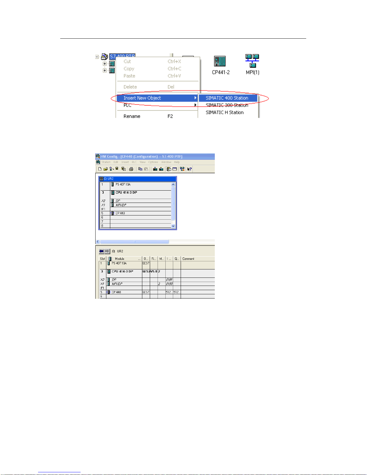
1. Open the project ptp that has been created, insert a new SIMATIC 400 Station,
and change the station name to CP441-2 modbus Slave.
2. Double-click Hardware to enter the hardware configuration interface, and insert
RACK, PS, CPU, and CP441-2. Please refer to the forgoing chapters for specific
steps.
3. In the CP441-2 module, click Parameter to configure CP441-2 parameters, and
select MODBUS Slave in Protocol options.
Fig. 112: Selecting communication protocol
4. Double-click the envelop icon under Protocol to configure MODBUS Slave
parameter:
Fig. 113: Configure MODBUS Slave communication parameter
5. Set the basic parameters such as communication rate and message details,
etc. In this example, the slave address is set as 100 (the default setting is 222, with
value range from 1 to 255). Then enter the slave function code configuration
interface. The detailed information is seen below:
Page 63

5 MODBUS RTU Protocol communication
CP340/CP341/CP440/CP441 Communication and Programming
Entry-ID: 88867653, V1.0, 02/2014
63
Siemens AG 2014 All rights reserved
Fig. 114: Distribution of MODBUS Slave addresses
6. FC01, 05, 15: status of read and forced output bit. The left side is info transfer
address, and the right side is corresponding PLC address area, viz. the left
addresses from 0 to 23 match MODBUS address area 00001 to 00024, and the
corresponding Siemens data area is M0.0-M2.7.24 to 47 match the MODBUS
Address area 00025 to 00048, and the corresponding Siemens data area is Q0.0
to Q2.7.Slave addresses 48 to 79 and 80 to 111 match the Modbus address areas
00049 to 00080 and 00081 to 00112, and the corresponding Siemens data area is
Timer, Counter. FC02 reads input data status, and the address matching is as
stated above.
Fig. 115: Distribution of MODBUS Slave addresses
7. FC03,06,16 configuration output register data area corresponds to Siemens
data area DB block.
Page 64

5 MODBUS RTU Protocol communication
CP340/CP341/CP440/CP441 Communication and Programming
Entry-ID: 88867653, V1.0, 02/2014
64
Siemens AG 2014 All rights reserved
Fig. 116: Distribution of MODBUS Slave addresses
8. FC04 configuration output register data area also corresponds to Siemens data
area DB block.
Fig. 117: Distribution of MODBUS Slave addresses
9. Set write parameter limit values of FC05,06,15,16 :
Fig. 118: Distribution of MODBUS Slave addresses
Page 65

5 MODBUS RTU Protocol communication
CP340/CP341/CP440/CP441 Communication and Programming
Entry-ID: 88867653, V1.0, 02/2014
65
Siemens AG 2014 All rights reserved
10. After completing configuration, click OK and save it, and close the dialog box.
Just like ASCII-2 as stated above, create PtP connection for the used interface,
and record the Local ID (Hex) connection number.
Fig. 119: Configuration connection
11. Click to compile the configuration information. If no error exists, select CPU
to download the configuration information as a whole, and use to check the
connection status online till "connection status" icon is displayed as:
to indicate correct connection. Just like MODBUS
communication with CP441, the "Startup" parameter in CPU properties shall also
be changed.
Fig. 120: Change "Startup" parameter in CPU properties
Page 66

5 MODBUS RTU Protocol communication
CP340/CP341/CP440/CP441 Communication and Programming
Entry-ID: 88867653, V1.0, 02/2014
66
Siemens AG 2014 All rights reserved
Set “Monitoring Time for” “Transfer of parameters to modules(100ms)” to a
value as small as 1000 (=100s), by which an adequately long time may be
guaranteed to download the used load protocol driver into the CP card during the
parameter assignment process.
5.4.3 Write communication program
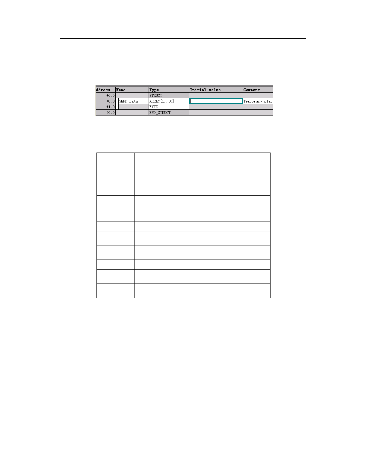
1. Double-click OB1 to open the programming screen. Invoke FB180 in Libraries > Modbus, and distribute instance data block DB180. The function code
communication data DB1 and DB2 for the newly created data block FC03 06 16
and FC04 are both in 50-word array structure.
Fig. 121: Communication data block DB1 and DB2
Page 67

5 MODBUS RTU Protocol communication
CP340/CP341/CP440/CP441 Communication and Programming
Entry-ID: 88867653, V1.0, 02/2014
67
Siemens AG 2014 All rights reserved
2. The FB180 parameter setting is shown in the table below:
Name
Data type
comments
ID
INPUT/INT
Local ID number, which is obtained from the
PtP connection properties and is
hexadecimal.
START_TIMER
INPUT/TIMER
Initialization timeout timer, which is T5 in
this example
START_TIME
INPUT/S5TIME
initialization timeout time value, which is 5s
in this example
STATUS_TIMER
INPUT/TIMER
communication status read timer, which is
T6 in this example
STATUS_TIME
INPUT/S5TIME
communication status read time value,
which is 2S in this example
OB_MASK
INPUT/BOOL
IO access error mask bit, which is M20.0 in
this example
0:Non-mask IO access error
1:Mask IO access error, and delaying the
alarm
CP_START
INPUT/BOOL
FB initialization enable bit, which is M20.1 in
this example
CP_START_FM
INPUT/BOOL
CP_START initialization rising edge bit,
which is M20.2 in this example
CP_NDR
OUTPUT/BOOL
CP write operation bit, which is M20.3 in this
example
CP_START_OK
OUTPUT/BOOL
initialization succeed complete bit, which is
M20.4 in this example
CP_START_ERR
OR
OUTPUT/BOOL
initialization error flag, which is M20.5 in this
example
ERROR_NR
OUTPUT/WORD
error number, which is MW22 in this
example
ERROR_INFO
OUTPUT/WORD
Error message, which is MW24 in this
example. Refer to the Manual for diagnosis
information
Table 15: Parameter definition of FB180
Page 68

5 MODBUS RTU Protocol communication
CP340/CP341/CP440/CP441 Communication and Programming
Entry-ID: 88867653, V1.0, 02/2014
68
Siemens AG 2014 All rights reserved
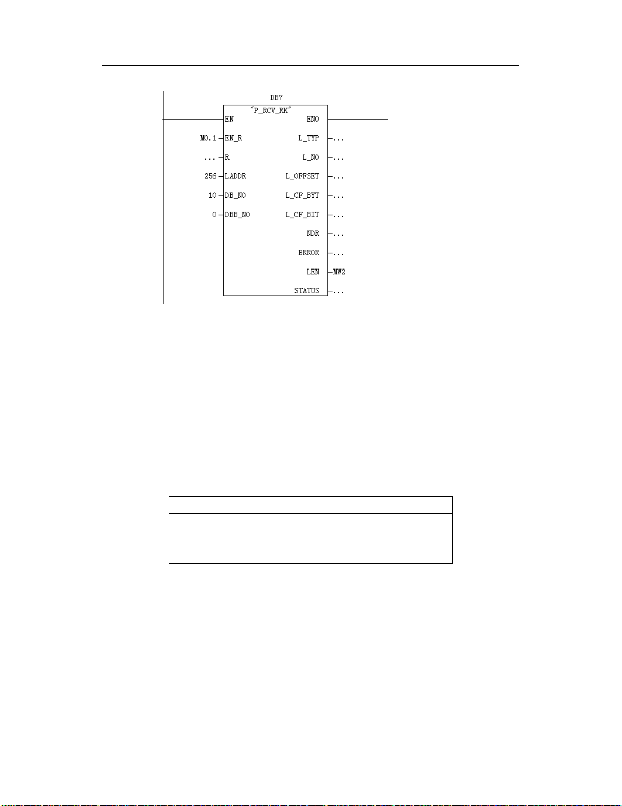
3. Invoke FB180 function block .
Fig. 122: Invoke FB180 function block
5.4.4 Equipment connection
Use standard RS232C cable to connect serial ports of CP341 and computer. The
detailed cable connecting method may be seen in CP341 Manual - Chapter B:
Connecting cables.
5.4.5 Communication test
Download the hardware configuration and program into CPU. Open the software
Modscan32 in the computer, and click Connection—〉Connect in Modscan32 to
display the following screen. Select the used serial port, and set Baud rate, data
bit, stop bit and check mode, and select a communication protocol according to the
applicable connection. After setting completes, click OK to display the monitor
screen.
Page 69

5 MODBUS RTU Protocol communication
CP340/CP341/CP440/CP441 Communication and Programming
Entry-ID: 88867653, V1.0, 02/2014
69
Siemens AG 2014 All rights reserved
Fig. 123: Distribute communication parameters
Fig. 124: Communication monitor interface
Modbus slave address
Modbus initial
address and
length
Type of data accessed by
Modbus, viz. selecting
function code to be used
corresponds
to Q0.0-
Q2.7 in PLC
Page 70

5 MODBUS RTU Protocol communication
CP340/CP341/CP440/CP441 Communication and Programming
Entry-ID: 88867653, V1.0, 02/2014
70
Siemens AG 2014 All rights reserved
Shown in the Fig. below is the corresponding communication monitor screen
when the function code FC04 is used. To read other data, just change the
related access data type. For floating point number display, refer to the read
method for Modbus Slave communication of CP341 as stated above.
Fig. 125: Communication monitor interface
corresponds to
 Loading...