

Siemens SIMATIC S7-400H User Manual

Important Notes, Contents
SIMATIC
S7-400H Programmable
Controller
Fault-Tolerant Systems
Manual
This manual has the order number:
6ES7988-8HA10-8BA0
Fault-Tolerant Systems in
Automation Engineering
S7-400H Installation Options
Getting Started
System and Operating Modes of
the S7-400H
Link-up and Update
Using I/O on the S7-400H
Communications
Configuring with STEP 7
Failure and Replacement of
Components During Operation
1
2
3
4
5
6
7
8
9
Edition 07/2000
A5E00068197-04
Modifications to the System while
in Operation
Appendices
Characteristic Values of
Redundant Programmable Logic
Controllers
Separate Operation
Converting from S5-H to S7-400H
Differences between
Fault-Tolerant Systems and
Standard Systems
Function Modules and
Communication Processors Used
on the S7-400H
Glossary, Index
10
A
B
C
D
E
Safety Guidelines
This manual contains notices which you should observe to ensure your own personal safety, as well as to
protect the product and connected equipment. These notices are highlighted in the manual by a warning
triangle and are marked as follows according to the level of danger:
!
!
!
Danger
indicates that death, severe personal injury or substantial property damage will result if proper precautions are not taken.
Warning
indicates that death, severe personal injury or substantial property damage can result if proper precautions are not taken.
Caution
indicates that minor personal injury or property damage can result if proper precautions are not taken.
Note
draws your attention to particularly important information on the product, handling the product, or to a
particular part of the documentation.
Qualified Personnel
Only qualified personnel should be allowed to install and work on this equipment. Qualified persons are
defined as persons who are authorized to commission, to ground, and to tag circuits, equipment, and systems in accordance with established safety practices and standards.
Correct Usage
Note the following:
Warning
!
Trademarks
Copyright Siemens AG 1998 All rights reserved
The reproduction, transmission or use of this document or its
contents is not permitted without express written authority.
Offenders will be liable for damages. All rights, including rights
created b y patent grant or registration of a utility model or design, are
reserved.
Siemens AG
Bereich Automatisierungs- und Antriebstechnik
Geschaeftsgebiet Industrie-Automatisierungssysteme
Postfach 4848, D- 90327 Nuernberg
Siemens Aktiengesellschaft A5E00068197
Index-2
This device and its components may only be used for the applications described in the catalog or the
technical descriptions, and only in connection with devices or components from other manufacturers
which have been approved or recommended by Siemens.
This product can only function correctly and safely if it is transported, stored, set up, and installed correctly, and operated and maintained as recommended.
SIMATIC, SIMATIC HMI and SIMATIC NET are registered trademarks of SIEMENS AG.
Some of other designations used in these documents are also registered trademarks; the owner’s rights
may be violated if they are used by third parties for their own purposes.
Disclaimer of Liability
We have checked the contents of this manual for agreement with the
hardware and software described. Since deviations cannot be precluded entirely, we cannot guarantee full agreement. However, the
data in this manual are reviewed regularly and any necessary corrections included in subsequent editions. Suggestions for improvement are welcomed.
Siemens AG 1998
Technical data subject to change.
S7-400H Programmable Controller Fault-Tolerant Systems
07/2000

Important Notes
Purpose of the manual
The present manual is intended for persons involved in the areas of configuration,
commissioning and servicing of programmable logic control systems.
To help you get familiar with the product, we recommend that you start with the
example in Chapter 3. It shows you an easy method of getting started on the subject
of fault-tolerant systems.
Basic knowledge required
In order to understand the manual, you will need to be familiar with the general
principles of automation technology.
Knowledge of S7 programs is also a prerequisite; you can read more about S7
programs in the
standard software while you are configuring, you should also be familiar with running
the standard software, as explained in the STEP 7 User Manual.
Programming with STEP 7
manual. As you need the STEP 7
Validity of the manual
The manual is valid for CPU 417-4H firmware version V2.1.0 or higher and option
package S7 H Systems, version V5.1 or higher.
S7-400H Programmable Controllers, Fault-Tolerant Systems
A5E00068197-04
iii

Important Notes
Online Help
In addition to the manual, detailed support on how to use the software is provided by
the online Help system integrated in the software.
The Help system can be accessed using a number of interfaces:
In the Help menu are a number of commands: Contents opens the Help index.
How to Use Help provides detailed instructions on how to use online Help.
Context-sensitive Help provides information on the current context – for
Another form of context-sensitive Help is the status bar. A brief explanation of
A brief explanation of the toolbar buttons is also shown when the mouse pointer
You will find help on fault-tolerant systems at Call Help on options packages,
configuring fault-tolerant systems.
example, on an open dialog box or an active window. It is accessed by means
of the “Help” button or F1.
each menu command is displayed here when you point the mouse pointer at
the menu command.
comes to rest for a short time on the buttons.
If you would like to read information from online Help in printed form, you can print
individual topics, books or the entire Help.
Feedback on documentation
We need your help to enable us to provide you and future users with optimum
documentation. Should you have any remarks on this
fill out the remarks form at the end of the manual and return it to the address shown
on the form. Please also indicate your personal opinion of the manual.
SIMATIC Training Center
We offer a number of courses to help you become familiar with the SIMATIC S7
programmable logic controller. Please contact your regional training center or the
central training center in D-90327 Nuremberg.
Phone: +49 (911) 895-3200.
Further support
The Nuremberg H/F Competence Center holds a special workshop on fault-tolerant
SIMATIC S7 programmable logic controllers. In addition, the H/F Competence Center
will provide on-site assistance with configuration, commissioning and other problems.
manual or online Help
, please
Further information can be obtained as follows:
Phone: +49 (911) 895-4759
Fax: +49 (911) 895-4519
iv
S7-400H Programmable Controllers, Fault-Tolerant Systems
A5E00068197-04

SIMATIC Customer Support Hotline
Available 24 hours a day, worldwide:
Nuremberg
Johnson City
SIMATIC Hotline
Important Notes
Singapore
Worldwide (Nuremberg)
T echnical Support
(FreeContact)
Local tim e : Mon. through
Fri. 7.00 a.m. to 5.00 p.m.
Phone: +49 (180) 5050-222
Fax: +49 (180) 5050-223
E-mail: techsupport@
ad.siemens.de
GMT: +1:00
Europe / Africa (Nuremberg)
Authorization
Local time: Mon. through
Fri. 7.00 a.m. to 5.00 p.m.
Phone: +49 (911) 895-7200
Fax: +49 (911) 895-7201
E-mail: authorization@
nbgm.siemens.de
GMT: +1:00
The SIMATIC Hotline languages are normally German and English; French, Italian and Spanish are also spoken on
the Authorization Hotline.
Worldwide (Nuremberg)
T echnical Support
(subject to charge, with SIMATIC Card
only)
Local time: Mon. through
Fri. 0.00 a.m. to 12.00 p.m.
Phone: +49 (911) 895-7777
Fax: +49 (911) 895-7001
GMT: +01.00
America (Johnson City)
T echnical Support and
Authorization
Local time: Mon. through
Fri. 8 a.m. to 5.00 p.m.
Phone: +1 423 461-2522
Fax: +1 423 461-2289
E-mail: simatic.hotline@
sea.siemens.com
GMT: –5:00
Asia/Australia (Singapore)
T echnical Support and
Authorization
Local time: Mon. through
Fri. 8.30 a.m. to 5.30 p.m.
Phone: +65 740-7000
Fax: +65 740-7001
E-mail: simatic.hotline@
sae.siemens.com.sg
GMT: +8:00
S7-400H Programmable Controllers, Fault-Tolerant Systems
A5E00068197-04
v

Important Notes
SIMATIC Customer Support Online Services
SIMATIC Customer Support provides you with comprehensive additional information
in SIMATIC products by means of its online services:
You can obtain up–to–date information
– on the Internet at http://www.ad.siemens.de/simatic
Current product information leaflets and downloads which you may find useful
for your product:
– on the Internet at http://www.ad.siemens.de/simatic–cs
– From our Bulletin Board System (BBS) in Nuremberg (
Support Mailbox)
by dialing +49 (911) 895-7100.
SIMATIC Customer
To dial the mailbox, use a modem having up to V.34 (28.8 kbps) and set its
parameters as follows: 8, N, 1, ANSI, or dial in using ISDN (x.75, 64 kbps).
You can find your local point–of–contact for Automation & Drives in our contacts
database
– on the Internet at
http://www3.ad.siemens.de/partner/search.asp
vi
S7-400H Programmable Controllers, Fault-T olerant Systems
A5E00068197-04

Contents
1 Fault-Tolerant Systems in Automation Engineering 1-1. . . . . . . . . . . . . . . . . . . . . . .
1.1 Redundant Programmable Logic Controllers in the SIMATIC Series 1-2. . . .
1.2 Increasing System Availability 1-4. . . . . . . . . . . . . . . . . . . . . . . . . . . . . . . . . . . . .
2 S7-400H Installation Options 2-1. . . . . . . . . . . . . . . . . . . . . . . . . . . . . . . . . . . . . . . . . . . .
2.1 Base System of the S7-400H 2-3. . . . . . . . . . . . . . . . . . . . . . . . . . . . . . . . . . . . .
2.2 I/O for the S7-400H 2-5. . . . . . . . . . . . . . . . . . . . . . . . . . . . . . . . . . . . . . . . . . . . . .
2.3 Communication 2-6. . . . . . . . . . . . . . . . . . . . . . . . . . . . . . . . . . . . . . . . . . . . . . . . .
2.4 Configuration and Programming Applications 2-7. . . . . . . . . . . . . . . . . . . . . . . .
2.5 User Program 2-8. . . . . . . . . . . . . . . . . . . . . . . . . . . . . . . . . . . . . . . . . . . . . . . . . . .
2.6 Documentation 2-9. . . . . . . . . . . . . . . . . . . . . . . . . . . . . . . . . . . . . . . . . . . . . . . . . .
3 Getting Started 3-1. . . . . . . . . . . . . . . . . . . . . . . . . . . . . . . . . . . . . . . . . . . . . . . . . . . . . . . . .
3.1 Requirements 3-2. . . . . . . . . . . . . . . . . . . . . . . . . . . . . . . . . . . . . . . . . . . . . . . . . . .
3.2 Configuring Hardware and Starting Up the S7-400H 3-3. . . . . . . . . . . . . . . . . .
3.3 Examples of Fault-Tolerant System Response in the Event of Faults 3-5. . .
4 System and Operating Modes of the S7-400H 4-1. . . . . . . . . . . . . . . . . . . . . . . . . . . . .
4.1 Introduction 4-2. . . . . . . . . . . . . . . . . . . . . . . . . . . . . . . . . . . . . . . . . . . . . . . . . . . . .
4.2 System Modes of the S7-400H 4-5. . . . . . . . . . . . . . . . . . . . . . . . . . . . . . . . . . . .
4.3 Operating Modes of the CPUs 4-6. . . . . . . . . . . . . . . . . . . . . . . . . . . . . . . . . . . .
4.3.1 STOP Operating Mode 4-7. . . . . . . . . . . . . . . . . . . . . . . . . . . . . . . . . . . . . . . . . . .
4.3.2 STARTUP Operating Mode 4-8. . . . . . . . . . . . . . . . . . . . . . . . . . . . . . . . . . . . . . .
4.3.3 LINK-UP and UPDATE Operating Modes 4-8. . . . . . . . . . . . . . . . . . . . . . . . . . .
4.3.4 RUN Operating Mode 4-9. . . . . . . . . . . . . . . . . . . . . . . . . . . . . . . . . . . . . . . . . . . .
4.3.5 HOLD Operating Mode 4-10. . . . . . . . . . . . . . . . . . . . . . . . . . . . . . . . . . . . . . . . . . .
4.3.6 ERROR-SEARCH Operating mode 4-11. . . . . . . . . . . . . . . . . . . . . . . . . . . . . . . .
4.4 Time Response 4-12. . . . . . . . . . . . . . . . . . . . . . . . . . . . . . . . . . . . . . . . . . . . . . . . .
5 Link-up and Update 5-1. . . . . . . . . . . . . . . . . . . . . . . . . . . . . . . . . . . . . . . . . . . . . . . . . . . . .
5.1 Effects of Link-up and Update 5-2. . . . . . . . . . . . . . . . . . . . . . . . . . . . . . . . . . . . .
5.2 Functional Sequence of Link-up and Update 5-3. . . . . . . . . . . . . . . . . . . . . . . .
5.2.1 Process of Link-up 5-7. . . . . . . . . . . . . . . . . . . . . . . . . . . . . . . . . . . . . . . . . . . . . .
5.2.2 Process of Updating 5-9. . . . . . . . . . . . . . . . . . . . . . . . . . . . . . . . . . . . . . . . . . . . .
5.2.3 Switch to CPU with modified configuration 5-12. . . . . . . . . . . . . . . . . . . . . . . . . .
5.2.4 Block Link-up and Update 5-13. . . . . . . . . . . . . . . . . . . . . . . . . . . . . . . . . . . . . . . .
5.3 Time Monitoring 5-15. . . . . . . . . . . . . . . . . . . . . . . . . . . . . . . . . . . . . . . . . . . . . . . . .
5.3.1 Time Behavior 5-17. . . . . . . . . . . . . . . . . . . . . . . . . . . . . . . . . . . . . . . . . . . . . . . . . .
5.3.2 Determination of the Monitoring Times 5-18. . . . . . . . . . . . . . . . . . . . . . . . . . . . .
5.3.3 Influences on the Time Behavior 5-26. . . . . . . . . . . . . . . . . . . . . . . . . . . . . . . . . . .
5.3.4 Performance Values for Link-up and Update 5-26. . . . . . . . . . . . . . . . . . . . . . . .
S7-400H Programmable Controller Fault-Tolerant Systems
A5E00068197-04
vii

Contents
5.4 Special Features during Link-up and Update 5-28. . . . . . . . . . . . . . . . . . . . . . . .
6 Using I/O on the S7-400H 6-1. . . . . . . . . . . . . . . . . . . . . . . . . . . . . . . . . . . . . . . . . . . . . . . .
6.1 Introduction 6-2. . . . . . . . . . . . . . . . . . . . . . . . . . . . . . . . . . . . . . . . . . . . . . . . . . . . .
6.2 Using a Single-Channel, One-Sided I/O 6-3. . . . . . . . . . . . . . . . . . . . . . . . . . . .
6.3 Using Single-Channel, Switched I/O 6-5. . . . . . . . . . . . . . . . . . . . . . . . . . . . . . .
6.4 Connecting a Redundant I/O 6-10. . . . . . . . . . . . . . . . . . . . . . . . . . . . . . . . . . . . . .
7 Communications 7-1. . . . . . . . . . . . . . . . . . . . . . . . . . . . . . . . . . . . . . . . . . . . . . . . . . . . . . .
7.1 Fundamentals and Basic Concepts 7-2. . . . . . . . . . . . . . . . . . . . . . . . . . . . . . . .
7.2 Suitable Networks 7-5. . . . . . . . . . . . . . . . . . . . . . . . . . . . . . . . . . . . . . . . . . . . . . .
7.2.1 Industrial Ethernet 7-5. . . . . . . . . . . . . . . . . . . . . . . . . . . . . . . . . . . . . . . . . . . . . . .
7.2.2 PROFIBUS 7-6. . . . . . . . . . . . . . . . . . . . . . . . . . . . . . . . . . . . . . . . . . . . . . . . . . . . .
7.3 Supported Communication Services 7-7. . . . . . . . . . . . . . . . . . . . . . . . . . . . . . .
7.4 Communications via Fault-Tolerant S7 Connections 7-7. . . . . . . . . . . . . . . . . .
7.4.1 Communications between Fault-Tolerant Systems 7-9. . . . . . . . . . . . . . . . . . .
7.4.2 Communications between Fault-Tolerant Systems and a
Fault-Tolerant CPU 7-11. . . . . . . . . . . . . . . . . . . . . . . . . . . . . . . . . . . . . . . . . . . . . .
7.4.3 Communications between Fault-Tolerant Systems and PCs 7-12. . . . . . . . . . .
7.5 Communications via S7 Connections 7-13. . . . . . . . . . . . . . . . . . . . . . . . . . . . . . .
7.5.1 Communications via S7 Connections – One-Sided Mode 7-13. . . . . . . . . . . . .
7.5.2 Communications over Redundant S7 Connections 7-15. . . . . . . . . . . . . . . . . . .
7.5.3 Communications via a Point-to-Point CP on the ET200M 7-16. . . . . . . . . . . . .
7.5.4 Random Connection with Single-channel Systems 7-17. . . . . . . . . . . . . . . . . . .
8 Configuring with STEP 7 8-1. . . . . . . . . . . . . . . . . . . . . . . . . . . . . . . . . . . . . . . . . . . . . . .
8.1 Installing the Options Package 8-2. . . . . . . . . . . . . . . . . . . . . . . . . . . . . . . . . . . .
8.2 Configuring with STEP 7 8-3. . . . . . . . . . . . . . . . . . . . . . . . . . . . . . . . . . . . . . . . .
8.2.1 Rules for H Station Equipment 8-3. . . . . . . . . . . . . . . . . . . . . . . . . . . . . . . . . . . .
8.2.2 Configuring Hardware 8-4. . . . . . . . . . . . . . . . . . . . . . . . . . . . . . . . . . . . . . . . . . . .
8.2.3 Configuring Networks 8-5. . . . . . . . . . . . . . . . . . . . . . . . . . . . . . . . . . . . . . . . . . . .
8.3 Programming Device Functions in STEP 7 8-6. . . . . . . . . . . . . . . . . . . . . . . . . .
9 Failure and Replacement of Components During Operation 9-1. . . . . . . . . . . . . . .
9.1 Failure and Replacement of Components in Central Racks
and Expansion Racks 9-2. . . . . . . . . . . . . . . . . . . . . . . . . . . . . . . . . . . . . . . . . . . .
9.1.1 Failure and Replacement of a Central Processing Unit CPU 417-4H 9-3. . . .
9.1.2 Failure and Replacement of a Power Supply Module 9-5. . . . . . . . . . . . . . . . .
9.1.3 Failure and Replacement of an Input/Output or Function Module 9-6. . . . . . .
9.1.4 Failure and Replacement of a Communication Processor 9-7. . . . . . . . . . . . .
9.1.5 Failure and Replacement of a Synchronization Submodule
or Fiber-Optic Cable 9-8. . . . . . . . . . . . . . . . . . . . . . . . . . . . . . . . . . . . . . . . . . . . .
9.1.6 Failure and Replacement of an IM 460 and IM 461 Interface Module 9-11. . .
9.2 Failure and Replacement of Components of the Distributed I/O 9-12. . . . . . . .
9.2.1 Failure and Replacement of a PROFIBUS-DP Master 9-13. . . . . . . . . . . . . . . .
9.2.2 Failure and Replacement of a redundant PROFIBUS-DP
Interface Module 9-14. . . . . . . . . . . . . . . . . . . . . . . . . . . . . . . . . . . . . . . . . . . . . . . .
S7-400H Programmable Controller Fault-Tolerant Systems
viii
A5E00068197-04

Contents
9.2.3 Failure and Replacement of a PROFIBUS-DP Slave 9-15. . . . . . . . . . . . . . . . .
9.2.4 Failure and Replacement of PROFIBUS-DP Cables 9-16. . . . . . . . . . . . . . . . . .
10 Modifications to the System while in Operation 10-1. . . . . . . . . . . . . . . . . . . . . . . . . . .
10.1 Possible Hardware Modifications 10-2. . . . . . . . . . . . . . . . . . . . . . . . . . . . . . . . . .
10.2 Adding Components in PCS7 10-6. . . . . . . . . . . . . . . . . . . . . . . . . . . . . . . . . . . . .
10.2.1 PCS7, Step 1: Modification of Hardware 10-7. . . . . . . . . . . . . . . . . . . . . . . . . . . .
10.2.2 PCS7, Step 2: Offline Modification of the Hardware Configuration 10-8. . . . . .
10.2.3 PCS7, Step 3: Stopping the Standby CPU 10-9. . . . . . . . . . . . . . . . . . . . . . . . . .
10.2.4 PCS7, Step 4: Loading new Hardware Configuration in
the Standby CPU 10-10. . . . . . . . . . . . . . . . . . . . . . . . . . . . . . . . . . . . . . . . . . . . . . . .
10.2.5 PCS7, Step 5: Switch to CPU with modified configuration 10-11. . . . . . . . . . . . .
10.2.6 PCS7, Step 6: Transition to the Redundant System Mode 10-13. . . . . . . . . . . . .
10.2.7 PCS7, Step 7: Changing and Loading User Program 10-14. . . . . . . . . . . . . . . . .
10.2.8 Use of free channels on an existing module 10-15. . . . . . . . . . . . . . . . . . . . . . . . .
10.3 Removing Components in PCS7 10-16. . . . . . . . . . . . . . . . . . . . . . . . . . . . . . . . . .
10.3.1 PCS7, Step I: Offline Modification of the Hardware Configuration 10-17. . . . . .
10.3.2 PCS7, Step II: Changing and Loading User Program 10-18. . . . . . . . . . . . . . . . .
10.3.3 PCS7, Step III: Stopping the Standby CPU 10-19. . . . . . . . . . . . . . . . . . . . . . . . .
10.3.4 PCS7, Step IV: Loading new Hardware Configuration in
the Standby CPU 10-19. . . . . . . . . . . . . . . . . . . . . . . . . . . . . . . . . . . . . . . . . . . . . . . .
10.3.5 PCS7, Step V: Switch to CPU with modified configuration 10-20. . . . . . . . . . . . .
10.3.6 PCS7, Step VI: Transition to the Redundant System Mode 10-22. . . . . . . . . . . .
10.3.7 PCS7, Step VII: Modification of Hardware 10-23. . . . . . . . . . . . . . . . . . . . . . . . . .
10.4 Adding Components in STEP 7 10-24. . . . . . . . . . . . . . . . . . . . . . . . . . . . . . . . . . .
10.4.1 STEP 7, Step 1: Modification of Hardware 10-25. . . . . . . . . . . . . . . . . . . . . . . . . .
10.4.2 STEP 7, Step 2: Offline Modification of the Hardware Configuration 10-26. . . .
10.4.3 STEP 7, Step 3: Expanding and Loading Organization Blocks 10-26. . . . . . . . .
10.4.4 STEP 7, Step 4: Stopping the Standby CPU 10-27. . . . . . . . . . . . . . . . . . . . . . . .
10.4.5 STEP 7, Step 5: Loading new Hardware Configuration in
the Standby CPU 10-27. . . . . . . . . . . . . . . . . . . . . . . . . . . . . . . . . . . . . . . . . . . . . . . .
10.4.6 STEP 7, Step 6: Switch to CPU with modified configuration 10-28. . . . . . . . . . .
10.4.7 STEP 7, Step 7: Transition to the Redundant System Mode 10-30. . . . . . . . . . .
10.4.8 STEP 7, Step 8: Changing and Loading User Program 10-31. . . . . . . . . . . . . . .
10.4.9 Use of free channels on an existing module 10-32. . . . . . . . . . . . . . . . . . . . . . . . .
10.5 Removing Components in STEP 7 10-33. . . . . . . . . . . . . . . . . . . . . . . . . . . . . . . . .
10.5.1 STEP 7, Step I: Offline Modification of the Hardware Configuration 10-34. . . . .
10.5.2 STEP 7, Step II: Changing and Loading User Program 10-35. . . . . . . . . . . . . . .
10.5.3 STEP 7, Step III: Stopping the Standby CPU 10-36. . . . . . . . . . . . . . . . . . . . . . . .
10.5.4 STEP 7, Step IV: Loading new Hardware Configuration
in the Standby CPU 10-36. . . . . . . . . . . . . . . . . . . . . . . . . . . . . . . . . . . . . . . . . . . . .
10.5.5 STEP 7, Step V: Switch to CPU with modified configuration 10-37. . . . . . . . . . .
10.5.6 STEP 7, Step VI: Transition to the Redundant System Mode 10-39. . . . . . . . . .
10.5.7 STEP 7, Step VII: Modification of Hardware 10-40. . . . . . . . . . . . . . . . . . . . . . . . .
10.5.8 STEP 7, Step VIII: Modifying and loading organization blocks 10-41. . . . . . . . .
10.6 Changing the CPU Parameters 10-42. . . . . . . . . . . . . . . . . . . . . . . . . . . . . . . . . . . .
10.6.1 Step A: Changing the CPU Parameters Offline 10-43. . . . . . . . . . . . . . . . . . . . . .
10.6.2 Step B: Stopping the Standby CPU 10-43. . . . . . . . . . . . . . . . . . . . . . . . . . . . . . . .
10.6.3 Step C: Loading new Hardware Configuration in the Standby CPU 10-44. . . . .
10.6.4 Step D: Switch to CPU with modified configuration 10-45. . . . . . . . . . . . . . . . . . .
S7-400H Programmable Controller Fault-Tolerant Systems
A5E00068197-04
ix

Contents
10.6.5 Step E: Transition to the Redundant System Mode 10-46. . . . . . . . . . . . . . . . . . .
10.7 Changing the Memory Components of the CPU 10-47. . . . . . . . . . . . . . . . . . . . .
10.7.1 Expand the main and/or load memory 10-47. . . . . . . . . . . . . . . . . . . . . . . . . . . . . .
10.7.2 Changing the type of load memory 10-49. . . . . . . . . . . . . . . . . . . . . . . . . . . . . . . . .
10.8 Perform operating system update 10-51. . . . . . . . . . . . . . . . . . . . . . . . . . . . . . . . . .
A Characteristic Values of Redundant Programmable Logic Controllers A-1. . . . . .
A.1 Basic Concepts A-2. . . . . . . . . . . . . . . . . . . . . . . . . . . . . . . . . . . . . . . . . . . . . . . . .
A.2 Comparison of MTBFs for Selected Configurations A-4. . . . . . . . . . . . . . . . . .
A.2.1 System Configurations With Central I/O A-4. . . . . . . . . . . . . . . . . . . . . . . . . . . .
A.2.2 System Configurations With Distributed I/O A-6. . . . . . . . . . . . . . . . . . . . . . . . .
A.2.3 Comparison of System Configurations With Standard and
Fault-Tolerant Communications A-8. . . . . . . . . . . . . . . . . . . . . . . . . . . . . . . . . . .
B Separate Operation B-1. . . . . . . . . . . . . . . . . . . . . . . . . . . . . . . . . . . . . . . . . . . . . . . . . . . . .
C Converting from S5-H to S7-400H C-1. . . . . . . . . . . . . . . . . . . . . . . . . . . . . . . . . . . . . . . .
C.1 General Information C-1. . . . . . . . . . . . . . . . . . . . . . . . . . . . . . . . . . . . . . . . . . . . .
C.2 Configuration, Programming and Diagnostics C-2. . . . . . . . . . . . . . . . . . . . . . .
D Differences between Fault-Tolerant Systems and Standard Systems D-1. . . . . . .
E Function Modules and Communication Processors Used on the S7-400H E-1. .
Glossary Glossary-1. . . . . . . . . . . . . . . . . . . . . . . . . . . . . . . . . . . . . . . . . . . . . . . . . . . . . . . . . .
Index Index-1. . . . . . . . . . . . . . . . . . . . . . . . . . . . . . . . . . . . . . . . . . . . . . . . . . . . . . . . . . . . . . . .
x
S7-400H Programmable Controller Fault-Tolerant Systems
A5E00068197-04

Fault-Tolerant Systems in Automation Engineering
This chapter contains an introduction to redundant and fault-tolerant programmable
logic controllers.
In Section You Will Find On Page
1.1 Redundant Programmable Logic Controllers in the SIMATIC
1.2 Increasing System Availability 1-4
1
1-2
Series
S7-400H Programmable Controller Fault-Tolerant Systems
A5E00068197-04
1-1
Fault-Tolerant Systems in Automation Engineering
1.1 Redundant Programmable Logic Controllers in the SIMATIC Series
Economic, and thus resource-sparing and low-pollution production can be
achieved nowadays in all branches of industry only by employing a high degree of
automation. At the same time there is a demand for fail-safe programmable logic
controllers with the greatest degree of distribution possible.
Redundant programmable logic controllers from Siemens have proved themselves
in operation and thousands are in service.
Perhaps you are already familiar with one of the fault-tolerant systems such as the
SIMATIC S5-115H and S5-155H, or the fail-safe S5-95F and S5-115F systems.
The S7-400H is the latest fault-tolerant PLC and we will be presenting it on the
pages that follow. It is a member of the SIMATIC S7 system family, meaning that
you can fully avail yourself of all the advantages of the SIMATIC S7.
Operating objectives of Redundant PLCs
Redundant programmable logic controllers are used in practice with the aim of
achieving a higher degree of availability or fault tolerance.
Redundant programmable logic
controllers, for example:
Fault-tolerant 1-out-of-2 systems
Objective:
Reduce the probability of losses of
production by switching to a standby
system
Figure 1-1 Operating Objectives of Redundant Programmable Logic Controllers
Fail-safe 2-out-of-2-systems
Objective:
Protect life, the environment and
investments by safely
disconnecting to a secure ”off”
position
Note the difference between fault-tolerant systems and fail-safe systems. The
S7-400H is a fault-tolerant programmable logic controller that can be used only
with additional means for controlling processes relevant to safety.
1-2
S7-400H Programmable Controller Fault-T olerant Systems
A5E00068197-04

Fault-Tolerant Systems in Automation Engineering
Why do we have fault-tolerant programmable logic controllers?
The objective of using high-availabilty programmable logic controllers is a reduction
of losses of production. It does not matter whether the losses are caused by an
error or as a result of maintenance work.
The higher the costs of a stoppage, the more worthwhile it is to use a fault-tolerant
system. The generally higher investment costs of fault-tolerant systems are quickly
compensated by the avoidance of losses of production.
Software redundancy
In a large number of applications, requirements in respect of the quality of
redundancy or the number of system sections that necessitate redundant PLCs
are not high enough to warrant the use of a specific fault-tolerant system.
Frequently, simple software mechanisms are sufficient to allow continuation of a
failed control task on a substitute system in the event of an error.
The “SIMATIC S7 Software Redundancy” options software can run on S7-300 and
S7-400 standard systems to control processes that tolerate transfer times to a
substitute system within seconds, such as water works, water treatment systems
or traffic flows.
S7-400H Programmable Controller Fault-T olerant Systems
A5E00068197-04
1-3
Fault-Tolerant Systems in Automation Engineering
1.2 Increasing System Availability
The S7-400H programmable logic controller meets these high requirements for
availability, intelligence and distribution that are required of state-of-the-art
programmable logic controllers. Further, it features all the functions for acquiring
and preparing process data and for controlling, regulating and monitoring units and
systems.
System-wide universality
The S7-400H programmable logic controller and all other SIMATIC components,
such as the SIMATIC PCS7 control system, are harmonized. Total system
universality, from the supervisory console to the sensors and actuators, is a matter
of course and guarantees maximum system performance.
Single-user
OS
*) not possible with firmware version 2.0.0
S7-300
ET 200B
Report printer
ET 200L
Server Server
S7-400
Client Client
S7-400H
system
ET 200M
ET 200X
Figure 1-2 Universal Automation Solutions with SIMATIC
Engineering
system
S7-400 with
CPU 417-4H *)
Bus link DP/PA
Supervisory console
LAN (redundant)
Programmable logic
controllers
PROFIBUS DP (redundant)
Distributed I/O
Sensors/
actuators
Graduated availability by duplicating components
The S7-400H is designed with redundancy so that it remains available at all
events. This means that all major components are duplicated.
The components that are duplicated as a matter of policy are the central
processing unit (CPU), the power supply and the hardware for interconnecting the
two central processing units.
You can decide for yourself whether you wish to duplicate more components for
the process you are going to automate and thus enhance their availability.
S7-400H Programmable Controller Fault-T olerant Systems
1-4
A5E00068197-04
Redundant nodes
Redundant nodes represent the fault tolerance of systems with redundant
components. The independence of a redundant node is given when the failure of a
component within the node does not result in reliability constraints in other nodes
or in the entire system.
The availability of the entire system can be illustrated in a simple manner by
means of a block diagram. With a 1-out-of-2 system, one component of the
redundant node may fail without impairing the operability of the overall system. The
weakest link in the chain of redundant nodes determines the availability of the
overall system.
Without malfunction (Figure 1-3).
Fault-Tolerant Systems in Automation Engineering
PS CPU
PS
CPU
Redundant nodes with 1-out-of-2 redundancy
Bus
Bus
IM 153-2
SM
IM 153-2
Figure 1-3 Example of Redundancy in a Network without Malfunction
With malfunction
In Figure 1-4, one component may fail per redundant node without the functionality
of the overall system being impaired.
Bus
Bus
CPU
CP
CP
Figure 1-4 Example of Redundancy in a 1-out-of-2 System with Malfunction
CP
CP
CPUCPU
CPU
Failure of a redundant node (total failure)
In Figure 1-5, the entire system is no longer operable since both subcomponents
have failed in a 1-out-of-2 redundant node (total failure).
PS CPU
PS
Redundant nodes with 1-out-of-2 redundancy
Figure 1-5 Example of Redundancy in a 1-out-of-2 System with Total Failure
S7-400H Programmable Controller Fault-T olerant Systems
A5E00068197-04
CPU
Bus
Bus
IM 153-2
SM
IM 153-2
1-5

Fault-Tolerant Systems in Automation Engineering
1-6
S7-400H Programmable Controller Fault-T olerant Systems
A5E00068197-04

S7-400H Installation Options
The first part of the description starts with the basic configuration of the
fault-tolerant S7-400H programmable controller and the components making up
the S7-400H base system. We then describe the hardware components with which
you can expand this base system.
The second part describes the software applications with which you can configure
and program the S7-400H. In addition, a description is given of the additions and
extensions, compared to the S7-400 standard system, that you will require for
programming your user program in order to be able to react specifically to the
properties of the S7-400H that enhance availability.
In Section You Will Find On Page
2.1 Base System of the S7-400H 2-3
2.2 I/O for the S7-400H 2-5
2.3 Communications 2-6
2.4 Configuration and Programming Applications 2-7
2.5 User Program 2-8
2.6 Documentation 2-9
2
S7-400H Programmable Controller Fault-Tolerant Systems
A5E00068197-04
2-1
S7-400H Installation Options
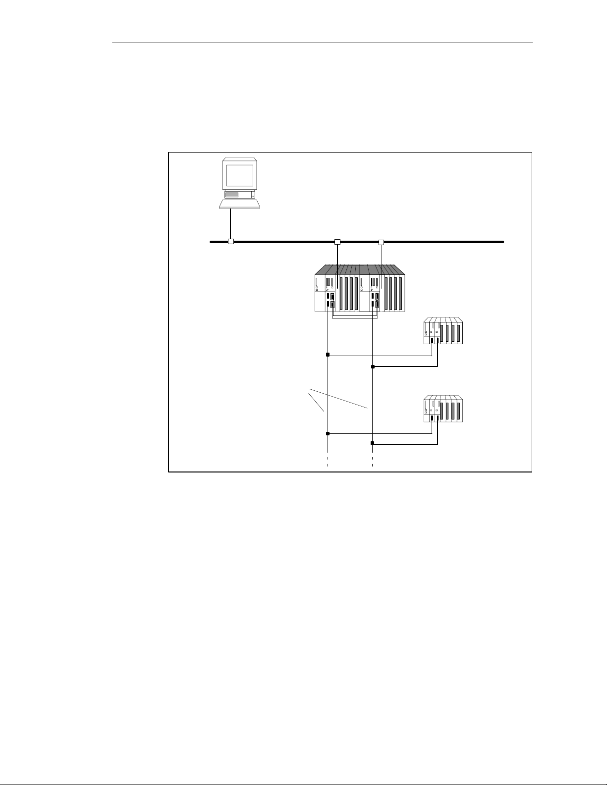
Figure 2-1 shows an example of the configuration of an S7-400H with common
distributed I/O and a connection to a redundant system bus. On the next few
pages we will describe step by step the hardware and software components
necessary for configuring and operating the S7-400H.
Operator station
(system visualization)
redundant system bus (PROFIBUS or Ethernet)
S7-400H PLC
ET 200M distributed I/O
redundant PROFIBUS-DP
Figure 2-1 Overview
Further information
The components of the S7-400 standard system are also used in the fault-tolerant
S7-400H programmable logic controller. A detailed description of all the hardware
components of the S7-400 and S7-400H may be found in the Reference Manual
S7-400, M7-400 Programmable Controllers, Module Specifications
The same rules as for a standard S7-400 system apply to designing the user
program and the usage of blocks for the fault-tolerant S7-400H programmable
logic controller. Please take note of the descriptions in the
STEP 7
Functions
manual and in the
ET 200M distributed I/O
.
Programming with
System Software for S7-300/400, System and Standard
Reference Manual.
2-2
S7-400H Programmable Controller Fault-T olerant Systems
A5E00068197-04
2.1 Base System of the S7-400H
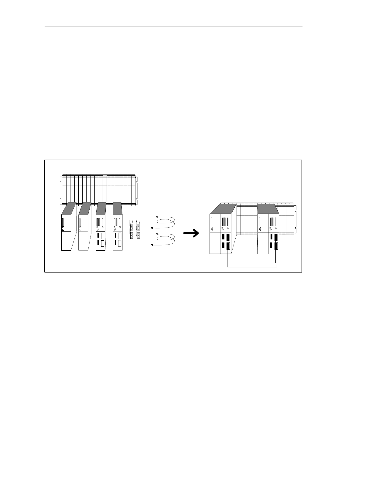
Hardware of the Base System
By base system of the S7-400H we mean the minimum configuration of the
S7-400H. The base system consists of all the requisite hardware components that
make up the fault-tolerant control system. Figure 2-2 shows the components in the
installation.
You can upgrade the base system by means of standard modules from the
S7-400. There are restrictions in the case of the function and communication
processors (see appendix E).
S7-400H Installation Options
Rack UR2H
2 PS 2 CPUs 2 fiber-optic cables
Figure 2-2 Hardware of the S7-400H Base System
4 synchronization
submodules
CPU 417-4 H central processing unit
At the heart of the S7-400H are the two central processing units CPU 417-4H.
Setting of the synchronization submodules, which have to be plugged into the
CPU, defines the rack numbers. In the following we will refer to the CPU in rack 0
as CPU 0,and to the CPU in rack 1 as CPU 1.
S7-400H base system
Rack 0
Rack 1
S7-400H Programmable Controller Fault-T olerant Systems
A5E00068197-04
2-3

S7-400H Installation Options
Mounting rack for S7-400H
We recommend you the UR2-H mounting rack for the S7-400H. The mounting rack
makes it possible to configure two separate subsystems, each containing nine
slots, and is suitable for installation in 19” cabinets.
Alternatively, you can also configure the S7-400H on two separate mounting racks.
Two mounting racks, the UR1 and UR2, are available for this purpose.
Power supply
As a power supply, you will require for each CPU 417-4 H – or, to be more precise,
for each of the two subsystems of the S7-400H – a power supply module from the
standard range of the S7-400.
Power supply modules for rated input voltages of 24 V DC and 120/230 V AC are
available with input powers of 4, 10 and 20 A.
To enhance the availability of the power supply, you can also use two redundant
power supplies in each subsystem. In this case you should use the PS 407 10 A R
power supply module for rated voltages of 120/230 V AC with an output power of
10 A.
Synchronization submodules
The synchronization submodules are used to connect the two central processing
units. They are installed in the central processing units and interconnected by
means of fiber-optic cables.
Two synchronization submodules have to be inserted in each CPU.
Fiber-optic cables
The fiber-optic cables are inserted into the synchronization submodules and form
the physical connection (redundant link) between the two central processing units.
You will find further information on handling and adjusting the synchronization
submodules and the fiber-optic cables in the
Controllers, Module Specifications
Programmable Controllers, Hardware and Installation
S7-400, M7-400 Programmable
Reference Manual and in the
Manual.
S7-400, M7-400
2-4
S7-400H Programmable Controller Fault-T olerant Systems
A5E00068197-04

2.2 I/O for the S7-400H
For the S7-400H you can use virtually any of the input/output modules featured in
the SIMATIC S7 system range. The I/O can be used in
• central racks
• expansion units
• distributed over PROFIBUS DP.
The function modules (FMs) and communication processors (CPs) that can be
used in the S7-400H will be found in Appendix E.
I/O configuration versions
In addition to the power supplies and central processing units that are always used
as redundant modules, there are the following configuration versions for the
input/output modules:
• Single-channel, one-sided configuration with normal availability
S7-400H Installation Options
With the single-channel, one-sided configuration single input/output modules
are present (single-channel). The input/output modules are located in just one
of the subsystems and are only addressed by that subsystem.
• Single-channel, switched configuration with enhanced availability
With the single-channel switched (distributed) configuration single input/output
modules are present (single-channel) but can be addressed by either
subsystem.
Further information
You will find detailed information on the usage of I/O in Chapter 6.
S7-400H Programmable Controller Fault-T olerant Systems
A5E00068197-04
2-5

S7-400H Installation Options
2.3 Communication
For communication tasks on the S7-400H you can use almost any communications
components offered in the SIMATIC system range.
This applies to communication components used either with central I/O or
distributed I/O such as
• system buses (Industrial Ethernet, PROFIBUS)
• point-to-point connection
Availability of communications
You can vary the availability of communications with the S7-400H. There are
different solutions for the S7-400H in keeping with your communication
requirements. They range from a simple linear network structure to a redundant
optical two-fiber loop.
Fault-tolerant communication over PROFIBUS or Industrial Ethernet is supported
entirely with S7 communication functions.
Programming and configuration
Apart from the use of additional hardware components, there are basically no
differences with regard to configuration and programming compared to standard
systems. Fault-tolerant connections have to be configured only; specific
programming is not necessary.
All communication functions required for operating fault-tolerant communications
have been integrated in the operating system of CPU 417-4H and run
automatically and in the background – for example, monitoring of the
communication connection or automatic switching to a redundant connection in the
event of a malfunction.
Further information
You will find detailed information on the subject of communications with the
S7-400H in Chapter 7.
2-6
S7-400H Programmable Controller Fault-T olerant Systems
A5E00068197-04

S7-400H Installation Options
2.4 Configuration and Programming Applications
The S7-400H is configured and programmed with STEP 7 just like any other
SIMATIC S7 programmable logic controller.
After configuration with STEP 7, you treat the S7-400H as a normal S7-400
system.
For you this means that you can use your full knowledge of the SIMATIC S7 and,
for example, only have to take minor constraints into account when writing your
user program. However, there are also H-specific additions to the configuration.
Redundant components are monitored by the operating system, which
independently performs switching in the event of a fault. You have already
configured the information required for this in STEP 7 and it is known to the
system.
You will find detailed information on this subject in online Help and in Chapter 8.
Requisite software
The software components specified in Section 8.1 are required for configuration
and programming.
Optional software
All standard tools, engineering tools and runtime software that can be used on the
S7-400 can, of course, also be used on the S7-400H.
S7-400H Programmable Controller Fault-T olerant Systems
A5E00068197-04
2-7

S7-400H Installation Options
2.5 User Program
The rules applicable to the design and programming of the standard S7-400
system apply similarly to the S7-400H.
The user programs are stored in an identical form in the two central processing
units and are executed simultaneously (event-synchronous).
From the viewpoint of user program execution, the S7-400H behaves in exactly the
same manner as a standard system. The synchronization functions are integrated
in the operating system and run automatically and totally in the background. There
is no need to take these functions into account in the user program.
In order to be able to react to the lengthening of the cycle time due to updating, for
example, a few specific blocks allow you to optimize your user program in this
respect.
Specific organization blocks and system functions for the S7-400H
Apart from the blocks that can be used on both the S7-400 and the S7-400H, there
are further additional blocks for the S7-400H with which you can influence the
redundancy functions.
You can react to redundancy errors of the S7-400H with the following organization
blocks:
• OB 70, I/O redundancy errors
• OB 72, CPU redundancy errors
Using system function SFC 90 “H_CTRL” you can inhibit and re-enable link-up and
updates of the 417-4H CPUs. You can also affect the scope and execution of the
cyclical self-test.
Note
With a fail-safe system, the periodic self-tests must not be inhibited and then
enabled again.
For more details refer to the manual
Controllers; Fail-Safe Systems.
Further information
S7-400F and S7-400FH Programmable
2-8
You will find detailed information on the programming of the above-mentioned
blocks in the manual called
Manual called
System Software for S7-300/400, System and Standard Functions
Programming with STEP 7
S7-400H Programmable Controller Fault-T olerant Systems
and in the Reference
A5E00068197-04
.
2.6 Documentation
The following illustration presents an overview of the description of the different
components and possibilities presented by the S7-400H PLC.
Subject Documentation
S7-400H Installation Options
Hardware:
CPU 417-4H
Redundancy-capable power supply
synchronization submodule
rack UR2-H
IM 153-2
H-specific programming:
S7-400H-specific OBs, SFC
S7-400H-specific expansion of the SSL,
events and help on error
Specifically for fault-tolerant systems:
Fault-tolerant Systems
Configuration Options for S7-400H
Getting Started
System Modes for S7-400H
Link-up and Update
I/O, Communications
Configuration with the STEP 7 Option Pack
Failure and Replacement, System Modification
Figure 2-3 User Documentation for Fault-Tolerant Systems
S7/M7-400 standard documentation
Installation
Module Specifications
Instruction List
ET 200M Distributed I/O
STEP 7 documentation
Programming with STEP 7 V5.0
System and Standard Functions
(manual and online Help)
S7-400H PLC
Fault-Tolerant Systems
(manual and online Help)
Note
You will find the manuals listed in Figure 2-3 on the S7-400H product CD.
S7-400H Programmable Controller Fault-T olerant Systems
A5E00068197-04
2-9

S7-400H Installation Options
2-10
S7-400H Programmable Controller Fault-T olerant Systems
A5E00068197-04

Getting Started
This guide walks you through the steps that have to be performed to commission
the system by means of a specific example and results in a working application.
You will learn how an S7-400H programmable logic controller operates and
become familiar with its response in the event of a fault.
It takes about one to two hours to work through this example, depending on your
previous experience.
In Section You Will Find On Page
3.1 Requirements 3-2
3.2 Configuring Hardware and Starting Up the S7-400H 3-3
3.3 Examples of Fault-Tolerant System Response in the Event of
Faults
3
3-5
S7-400H Programmable Controller Fault-Tolerant Systems
A5E00068197-04
3-1

Getting Started
3.1 Requirements
The following requirements must be met:
A permitted version of the STEP 7 standard software and the ”S7 Fault-Tolerant
System” option pack are correctly installed on your programming device (refer to
Section 8.1).
You must have the modules required for the hardware configuration:
• an S7-400H PLC consisting of:
– 1 mounting rack, UR2-H
– 2 power supplies, PS 407 10A
– 2 CPU 417-4 H
– 4 synchronization submodules
– 2 fiber-optic cables
• an ET 200M distributed I/O device having an active backplane bus with
– 2 IM 153-2
– 1 digital input module, SM321 DI 16 x DC24V
– 1 digital output module, SM322 DO 16 x DC24V
• the necessary accessories such as PROFIBUS shielded cables, etc.
3-2
S7-400H Programmable Controller Fault-Tolerant Systems
A5E00068197-04
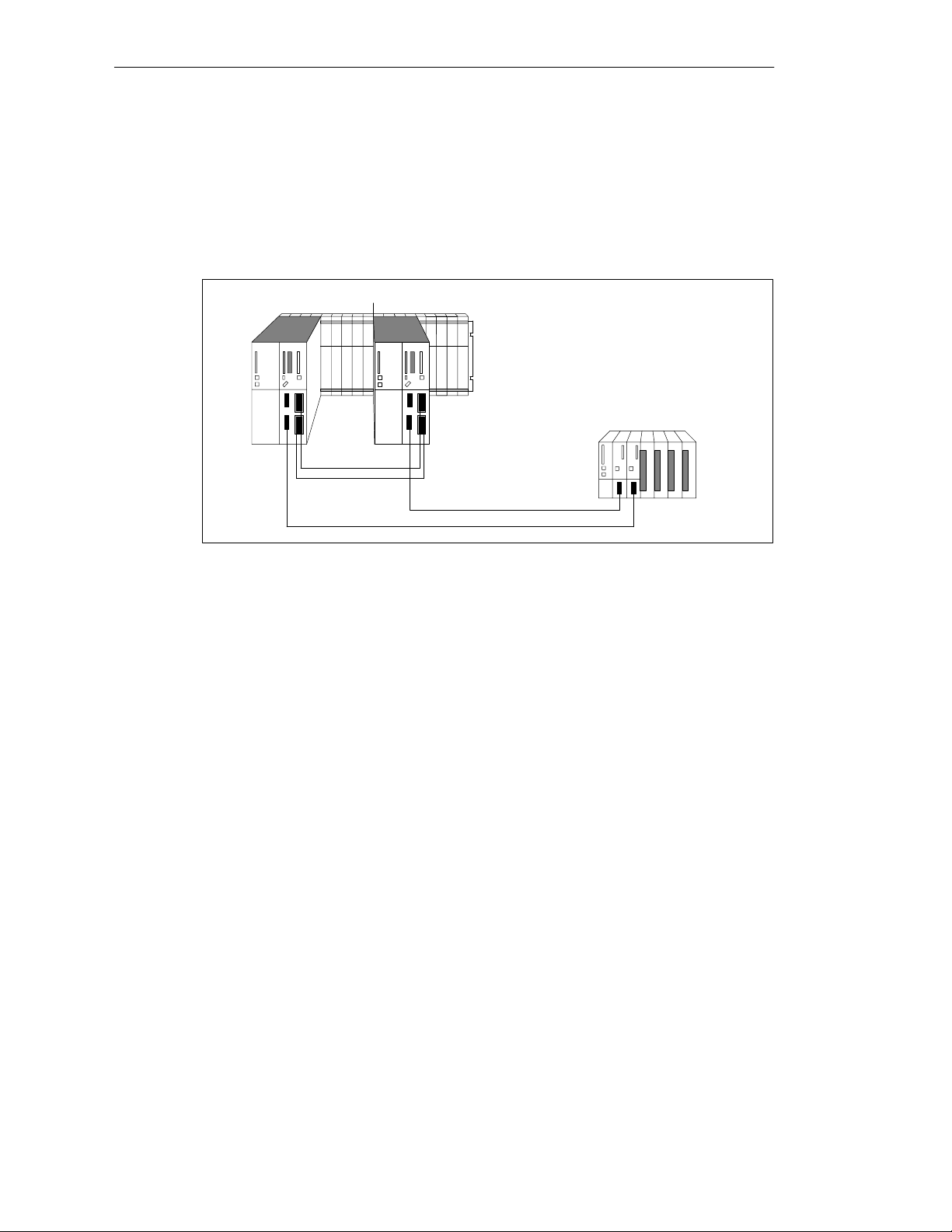
3.2 Configuring Hardware and Starting Up the S7-400H
Installing Hardware
To configure the S7-400H as illustrated in Figure 3-1, perform the following steps:
Rack 0 Rack 1
S7-400H PLC
ET 200M
distributed I/O
Getting Started
Figure 3-1 Hardware Configuration
1. Configure the two subunits of the S7-400H PLC as described in the
M7-400 Programmable Controllers, Hardware and Installation/Module
Specifications
manuals. In addition, you must:
– Set the mounting rack number by means of the switches on the
synchronization submodules. The setting is applied by the CPU after
POWER ON and a subsequent memory reset by means of the mode
selector. If the mounting rack number is not set correctly you will not have
online access and the CPU will not run in certain circumstances.
– Insert the synchronization submodules into the CPUs. Then screw up the
additional front bezels to activate them (refer to
Programmable Controllers, Hardware and Installation
S7-400, M7-400
).
– Connect the fiber-optic cables (always connect the two upper
synchronization submodules and the two lower synchronization submodules
of the CPUs). Lay the fiber-optic cable so that it is protected from any
damage.
Make sure with the route wires in addition that the two fiber-optic cables are
always laid so that they are isolated from each other. Laying them
separately enhances their availability and protects then from potential dual
faults in the event, say, of simultaneous interruption of the fiber-optic cables.
In addition, make sure that the fiber -opt ic cables are plugged into the two CPUs
before turning on the power supply or turning on the system. If they are not, the
two CPUs might bot h process the user program as master CPUs.
S7-400,
2. Configure the distributed I/O as described in the
Device
S7-400H Programmable Controller Fault-Tolerant Systems
A5E00068197-04
manual.
ET 200M Distributed I/O
3-3

Getting Started
3. Connect the programming device to the first CPU 417-4 H (CPU0). This CPU
4. A high-quality RAM test is performed after power on. It requires approximately
5. Perform a memory reset for both CPUs using the mode selector. This applies
should be the master CPU of the S7-400H.
8 seconds per megabyte of RAM. During this time the CPU cannot be
addressed via the multipoint interface and the STOP LED flashes. If there is a
backup battery, the test will not be performed on further POWER ONs.
the set mounting rack numbers of the synchronization modules to the
operating system of the CPU.
6. Perform commissioning individually for each CPU as described in the
M7-400 Programmable Controllers, Hardware and Installation
loading the program carry out a warm restart: first for the CPU you want as
the master CPU, and then for the standby CPU.
7. Switch the two CPUs of the S7-400H to STOP.
Starting up the S7-400H
To start up the S7-400H, perform the following steps:
1. Open the “HProject” in SIMATIC Manager. The configuration is the same as
the hardware configuration described in “Requirements”.
2. Open the hardware configuration of the project by selecting the “Hardware”
object and execute the pop-up menu command Object > Open with the right
mouse button. When you have an identical configuration, you can proceed
with step 6.
3. If your hardware configuration is different from that of the project – for
example, the module types, MPI addresses or DP address – you must adjust
and save the project accordingly. You will find descriptions in the basic help for
SIMATIC Manager.
4. Open the user program in the “S7 program” folder.
The “S7 program” folder is assigned only to CPU0 in the offline view. The user
program can run on the hardware configuration described. It makes the LEDs
on the digital output module light up in the form of a running light.
S7-400,
manual. After
3-4
5. If necessary, modify the user program – to adapt it to your hardware
configuration, for example – and save it.
6. Load the user program into CPU0 with the menu command PLC > Load.
7. Start the S7-400H PLC by switching the mode selector, first for CPU0 and
then for CPU1, to RUN-P.
Result: CPU0 starts up as the master CPU and CPU1 as the standby CPU.
After the link-up and update of the standby CPU the S7-400H switches to the
Redundant system mode and executes the user program (run light on digital
output module).
S7-400H Programmable Controller Fault-Tolerant Systems
A5E00068197-04
 Loading...