

Siemens simatic s7-400 FM 450-1 User Manual

Counter module FM 450-1
___________________
___________________
___________________
___________________
___________________
___________________
___________________
___________________
___________________
___________________
___________________
___________________
___________________
___________________
___________________
SIMATIC
S7-400
Counter module FM 450-1
Manual
02/2014
A5E03648739
Preface
Product Overview
1
This is how the FM 450-1
counts
2
Installation and Removal
3
Wiring
4
Parameter assignment
5
Program
6
Commissioning
7
Modes, settings, parameters
and commands
8
Encoder signals and their
evaluation
9
Assignment of the DB
10
Errors and diagnostics
11
Technical Data
12
Spare parts
13
References
14
-02
Siemens AG
Industry Sector
Postfach 48 48
90026 NÜRNBERG
GERMANY
A5E03648739-02
Ⓟ
Copyright © Siemens AG 2014.
All rights reserved
Legal information
Warning notice system
DANGER
indicates that death or severe personal injury will result if proper precautions are not taken.
WARNING
indicates that death or severe personal injury may result if proper precautions are not taken.
CAUTION
indicates that minor personal injury can result if proper precautions are not taken.
NOTICE
indicates that property damage can result if proper precautions are not taken.
Qualified Personnel
personnel qualified
Proper use of Siemens products
WARNING
Siemens products may only be used for the applications described in the catalog and in the relevant technical
enance are required to ensure that the products operate safely and without any problems. The permissible
ambient conditions must be complied with. The information in the relevant documentation must be observed.
Trademarks
Disclaimer of Liability
This manual contains notices you have to observe in order to ensure your personal safety, as well as to prevent
damage to property. The notices referring to your personal safety are highlighted in the manual by a safety alert
symbol, notices referring only to property damage have no safety alert symbol. These notices shown below are
graded according to the degree of danger.
If more than one degree of danger is present, the warning notice representing the highest degree of danger will
be used. A notice warning of injury to persons with a safety alert symbol may also include a warning relating to
property damage.
The product/system described in this documentation may be operated only by
task in accordance with the relevant documentation, in particular its warning notices and safety instructions.
Qualified personnel are those who, based on their training and experience, are capable of identifying risks and
avoiding potential hazards when working with these products/systems.
for the specific
Note the following:
documentation. If products and components from other manufacturers are used, these must be recommended
or approved by Siemens. Proper transport, storage, installation, assembly, commissioning, operation and
maint
All names identified by ® are registered trademarks of Siemens AG. The remaining trademarks in this publication
may be trademarks whose use by third parties for their own purposes could violate the rights of the owner.
We have reviewed the contents of this publication to ensure consistency with the hardware and software
described. Since variance cannot be precluded entirely, we cannot guarantee full consistency. However, the
information in this publication is reviewed regularly and any necessary corrections are included in subsequent
editions.
03/2014 Subject to change

Preface
Purpose of this manual
Basic knowledge required
Scope of this manual
Standards
Recycling and disposal
Additional support
This manual describes all steps required to use the FM 450-1 function module efficiently. It
supports you in installing and commissioning the module. The procedures for installing and
removing, wiring, assigning parameters, and programming are explained.
This manual is intended for the programmers of STEP 7 programs and for those responsible
for configuring, commissioning, and servicing automation systems.
This manual requires general knowledge of automation engineering.
You also require knowledge of the use of computers or PC-type equipment (such as
programming devices) based on a Windows 95/98/2000 or NT operating system as well as
STEP 7 programming skills.
The present manual contains the description of the FM 450-1 valid at the time the manual is
published. We reserve the right to describe changes to the functions of the FM 450-1 in the
form of product information.
The S7-400 automation system meets the requirements and criteria of IEC 61131-2.
Owing to the fact that its equipment is low in contaminants, the FM 450-1 can be recycled.
For environmentally compliant recycling and disposal of your discarded device, please
contact a company certified for the disposal of electronic waste.
If you have any further questions about the use of products described in this manual and do
not find the right answers here, contact your local Siemens representative
(http://www.siemens.com/automation/partner):
A guide to the technical documentation for the various products and systems is available on
the Internet:
Counter module FM 450-1
Manual, 02/2014, A5E03648739-02
● SIMATIC Guide manuals (http://www.siemens.com/simatic-tech-doku-portal)
The online catalog and online ordering systems are also available on the Internet:
● A&D Mall (http://www.siemens.com/automation/mall)
3

Preface
Training center
Technical Support
Service & Support on the Internet
To help you get started with automation technology and systems, we offer a variety of
courses. Contact your regional Training Center or the central Training Center in
D-90327 Nuremberg, Germany.
● Internet: SITRAIN homepage (http://www.sitrain.com)
You can access technical support for all A&D projects via the following:
● Online support request form: (http://www.siemens.com/automation/support-request)
In addition to our documentation, we offer a comprehensive online knowledge base on the
Internet at:
Industry Automation and Drive Technologies - Homepage
(http://www.siemens.com/automation/service&support)
There you will find the following information, for example:
● The newsletter that provides up-to-date information on your products.
● The documents you need via our Search function in Service & Support.
● A forum for global information exchange by users and specialists.
● Your local partner for Automation and Drives.
● Information about on-site service, repairs, and spare parts. Much more can be found
under "Services".
Counter module FM 450-1
4 Manual, 02/2014, A5E03648739-02

Table of contents
Preface ................................................................................................................................................... 3
1 Product Overview .................................................................................................................................... 9
2 This is how the FM 450-1 counts ........................................................................................................... 19
3 Installation and Removal ....................................................................................................................... 23
4 Wiring ................................................................................................................................................... 27
5 Parameter assignment .......................................................................................................................... 41
6 Program ................................................................................................................................................ 45
1.1 Chapter overview ........................................................................................................................... 9
1.2 Properties ..................................................................................................................................... 10
1.3 Fields of applications of the FM 450-1 ......................................................................................... 12
1.4 The FM 450-1 hardware .............................................................................................................. 13
1.5 The FM 450-1 software ................................................................................................................ 16
2.1 Basics ........................................................................................................................................... 19
2.2 Gate functions .............................................................................................................................. 22
3.1 Chapter overview ......................................................................................................................... 23
3.2 Preparing for Mounting ................................................................................................................ 24
3.3 Installing the FM 450-1 ................................................................................................................ 25
3.4 Removal of the FM 450-1 ............................................................................................................ 26
4.1 Chapter overview ......................................................................................................................... 27
4.2 Terminal assignment of the front connector ................................................................................ 28
4.3 Wiring Front Connectors .............................................................................................................. 35
4.4 Module status after power is switched on .................................................................................... 39
5.1 Chapter overview ......................................................................................................................... 41
5.2 Installing and calling parameter assignment screen forms .......................................................... 42
6.1 Chapter overview ......................................................................................................................... 45
6.2 The FC CNT_CTRL function ........................................................................................................ 46
6.3 The FC DIAG_INF function .......................................................................................................... 50
6.4 Example application ..................................................................................................................... 51
6.5 Technical specifications of the blocks .......................................................................................... 53
Counter module FM 450-1
Manual, 02/2014, A5E03648739-02
5

Table of contents
7 Commissioning ..................................................................................................................................... 55
8 Modes, settings, parameters and commands ........................................................................................ 65
9 Encoder signals and their evaluation ..................................................................................................... 93
10 Assignment of the DB .......................................................................................................................... 103
11 Errors and diagnostics ......................................................................................................................... 107
12 Technical Data ..................................................................................................................................... 115
7.1 Chapter overview ........................................................................................................................ 55
7.2 Working steps during mechanical installation ............................................................................. 56
7.3 Working steps for parameter assignment ................................................................................... 59
8.1 Chapter overview ........................................................................................................................ 65
8.2 Overview of modes, settings and commands ............................................................................. 66
8.3 Basics on calling modes, settings and commands ..................................................................... 68
8.4 Infinite counting ........................................................................................................................... 69
8.5 Single counting ............................................................................................................................ 71
8.6 Periodic counting ......................................................................................................................... 73
8.7 Count range ................................................................................................................................ 75
8.8 Setting: Behavior of the digital outputs ....................................................................................... 76
8.9 Setting: Pulse duration ................................................................................................................ 79
8.10 Command: Open and close gate ................................................................................................ 80
8.11 Command: Set counter ............................................................................................................... 83
8.12 Initiating a process interrupt ........................................................................................................ 90
9.1 Chapter overview ........................................................................................................................ 93
9.2 Encoders which can be connected ............................................................................................. 94
9.3 5-V differential signals ................................................................................................................. 95
9.4 24-V signals ................................................................................................................................ 97
9.5 Signal evaluation ....................................................................................................................... 100
10.1 Assignment of the DB ............................................................................................................... 103
11.1 Chapter overview ...................................................................................................................... 107
11.2 Faults indicated via the diagnostics LEDs ................................................................................ 108
11.3 Initiation of diagnostics interrupts .............................................................................................. 109
11.4 Data error .................................................................................................................................. 112
11.5 Operator error ........................................................................................................................... 113
12.1 General technical specifications ............................................................................................... 115
12.2 Technical Data .......................................................................................................................... 116
Counter module FM 450-1
6 Manual, 02/2014, A5E03648739-02

Table of contents
13 Spare parts ......................................................................................................................................... 119
14 References ......................................................................................................................................... 121
Glossary ............................................................................................................................................. 123
Index................................................................................................................................................... 127
Counter module FM 450-1
Manual, 02/2014, A5E03648739-02
7

Table of contents
Counter module FM 450-1
8 Manual, 02/2014, A5E03648739-02

1
1.1
Chapter overview
Section overview
This section provides you with an overview of the FM 450-1 function module.
● It informs you of what the FM 450-1 can do.
● Examples demonstrate some of the possible applications of the FM 450-1.
● You will learn how the FM 450-1 is integrated into the S7-400 automation system, and
familiarize yourself with the vital components of FM 450-1.
Counter module FM 450-1
Manual, 02/2014, A5E03648739-02
9

Product Overview
1.2
Properties
Properties
Comparison values
Load value
Hardware interrupts
1.5 The FM 450-1 software
The FM 450-1 is a fast counter module to be used in the S7-400 automation system. There
are two counters on the module which can work in the following counting ranges as required:
● 0 to 4 294 967 295 (0 to 2
● - 2 147 483 648 to + 2 147 483 647 (-2
The maximum input frequency of the counter signals is up to 500 kHz depending on the
encoder signal.
The FM 450-1 can be used for the following counting tasks:
● Continuous counting
● Single counting
● Periodic counting
You can start and stop the count either via the user program (software gate) or via external
signals (hardware gate).
32
- 1)
31
to 231 - 1).
You can store two comparison values per counter on the module; they are assigned to the
two corresponding outputs on the module. If the counter status reaches one of the
comparison values, then the output assigned to it can be set so that it triggers control
operations directly in the process.
You can determine an initial value (load value) for each counter on the FM 450-1 The
counter is set at the initial value if a software or hardware-related signal to the module comes
up.
When comparison values are reached, for overflow, underflow and/or for zero crossing of a
counter, the FM 450-1 can trigger a Hardware interrupt.
Counter module FM 450-1
10 Manual, 02/2014, A5E03648739-02

Product Overview
Diagnostic interrupt
Pulse duration
Which signals can the FM 450-1 count?
Input filter
Characteristics
Input filter 1
(default)
Input filter 2
Typical input delay
1 μs
15 μs
Maximum count frequency
200 kHz
20 kHz
Minimum pulse width of the count signals
2.5 μs
25 μs
1.5 The FM 450-1 software
When the following events occur, the FM 450-1 can trigger a diagnostic interrupt:
● External auxiliary voltage faulty
● Encoder 5.2 VDC supply faulty
● Module not assigned parameters or errors in parameter assignment
● Watchdog timeout
● RAM defective
● Hardware interrupt lost
● Fault in signal A, B, or N of the 5 V encoder
You can determine a pulse duration for the digital outputs of the FM 450-1. The pulse
duration is used to specify how long the corresponding digital output is to be set. You can
specify a value between 0 and 500 ms for the pulse duration. This value applies to both
outputs. By prescribing a pulse duration you can adapt the FM 450-1 to existing actors.
The FM 450-1 can count signals that are generated by the following encoders:
● Incremental 5-V encoders
● Incremental 24-V encoders
● 24-V pulse encoders with direction level
● 24-V initiators without direction level
e.g., light barrier or BERO
For the purpose of suppressing interference, you can assign input filters (RC elements) with
a uniform filter time for the 24 V inputs A*, B*, and N* and for the digital inputs. The following
two input filters are available:
Table 1- 1 Input filter
Counter module FM 450-1
Manual, 02/2014, A5E03648739-02
11
Product Overview
1.3
Fields of applications of the FM 450-1
You can use the FM 450-1 as follows:
Example application for an FM450-1
1.5 The FM 450-1 software
The main field of application of the FM 450-1 is where it is necessary to count signals with
high frequencies and fast reactions must be triggered when a prescribed counter reading is
reached.
Examples are:
● Packaging plants,
● sorting plants,
● dosing plants
Here a specific number of parts is to be filled into a box. An FM 450-1 counter assumes the
job of counting the parts and controlling the two motors for transporting the parts and the
box.
If the box is in the right position, belt A is stopped via the light barrier, the counting process is
started and the motor for belt B switched on. If the programmed number of parts are in the
box, the FM 450-1 stops the motor for belt B and switches on the motor for belt A so that the
box can be transported away. The counting process can start again when the next box
reaches the light barrier
Figure 1-1 Example application for an FM450-400 in the S7-400
Counter module FM 450-1
12 Manual, 02/2014, A5E03648739-02
Product Overview
1.4
The FM 450-1 hardware
View of module
Order number and version
1.5 The FM 450-1 software
The illustration shows the FM 450-1 module with front connector plugged in.
Figure 1-2 Illustration of the FM 450-1
The full order number of the FM 450-1 is shown on the rating plate.
The abbreviated order number and the version of the FM 450-1 are marked on the top end of
the front of the module.
Counter module FM 450-1
Manual, 02/2014, A5E03648739-02
13

Product Overview
Diagnostic and status LEDs
Labeling
Color
Function
INTF
Red
Internal error
EXTF
Red
External error
CH2 CR
CH2 DIR
CH2 IN 0
CH2 IN 1
CH2 IN 2
CH2 OUT 0
Front connectors
1.5 The FM 450-1 software
The FM 450-1 has 16 LEDs. The LEDs are for diagnostic purposes and indicate the state of
the FM 450-1 and its digital inputs and outputs. The following table lists labeling, color and
function of the LED displays.
Table 1- 2 Labeling, color and function of the LEDs
CH1 CR
CH1 DIR
CH1 IN 0
CH1 IN 1
CH1 IN 2
CH1 OUT 0
CH1 OUT 1
CH2 OUT 1
Green Counter in operation; status of the lowest value bit of counter 1 (CH 1) or
counter 2 (CH2)
Green Count direction; LED illuminated if counter 1 (CH1) or counter 2 (CH2) is
counting backwards.
Green Status of input 1I0 of counter 1 and/or 2I0 of counter 2
Green Status of input 1I1 of counter 1 and/or 2I1 of counter 2
Green Status of input 1I2 of counter 1 and/or 2I2 of counter 2
Green Status of output 1Q0 of counter 1 and/or 2Q0 of counter 2
Green Status of output 1Q1 of counter 1 and/or 2Q1 of counter 2
The front connector has the following terminals:
● 5-V or 24-V encoder signals for counters 1 and 2
● Encoder supply
Counter module FM 450-1
14 Manual, 02/2014, A5E03648739-02
● Digital input signals to start, stop and set counters 1 and 2
● Digital output signals Q0 and Q1 for counters 1 and 2
● Auxiliary voltage 1L+ to generate the encoder supply voltages
● Load voltage 2L+ to supply the digital outputs
The front connector can be ordered separately (see chapter "Spare parts (Page 119)").

Product Overview
Front connector coding
Labeling strips
1.5 The FM 450-1 software
If you hook in the front connector, the front connector coding engages. Thereafter this front
connector can only be attached to an FM 450-1 module.
A plate block with four labeling strips is included with the module. These strips can be
labeled individually with the corresponding signal names.
Counter module FM 450-1
Manual, 02/2014, A5E03648739-02
15

Product Overview
1.5
The FM 450-1 software
Software packages of the FM 450-1
parameter assignment screen forms
1.5 The FM 450-1 software
You will require the software package on the supplied CD to integrate the FM 450-1 into the
S7-400. It includes:
● Parameterization software with parameterization interfaces
● Software for the CPU (blocks)
● Documentation
The FM 450-1 is adapted to the respective task via parameters. These parameters are
stored in an SDB and transferred to the module by the CPU.
The parameters can be determined via the parameter assignment screen forms. These
parameter assignment screen forms are installed on your programming device and opened
in STEP 7.
Counter module FM 450-1
16 Manual, 02/2014, A5E03648739-02
Product Overview
Software for the S7-400-CPU
1.5 The FM 450-1 software
The software for the CPU consists of the FC CNT_CTRL function, which is invoked in the
CPU user program. This FC enables communication between the CPU and the FM 450-1. In
addition, there is also the FC DIAG_INF for the FM 450-1 with which you can transmit
diagnostic data into the DB of FC CNT_CTRL.
This figure shows an S7-400 layout with an FM 450-1 and several signal modules.
Figure 1-3 Layout of a SIMATIC S7-400 with an FM 450-1
Counter module FM 450-1
Manual, 02/2014, A5E03648739-02
17

Product Overview
1.5 The FM 450-1 software
Counter module FM 450-1
18 Manual, 02/2014, A5E03648739-02

2
2.1
Basics
What is counting?
Count range, count limits
Count range
Low count limit
High count limit
0 to +32 bit
-31 to +31 bit
Load value
Comparison values
Operating modes
Counting refers to the recording and totaling of events. In the case of the FM 450-1 function
module encoder signals are captured and evaluated accordingly.
The FM 450-1 can count both forwards and backwards. When you select the count range,
you determine the limits between which the FM 450-1 can count.
Count range 1:
Count range 2:
You can lay down an initial value for each of the two FM 450-1 counters from which the
counting is to begin. This initial value is the load value. You can specify any value within the
count limits for the load value.
You can use two digital outputs on the module for each counter in order to trigger reactions
in a process at a certain counter reading, independently of the CPU. You store two
comparison values for each counter on the FM 450-1. If the counter reading reaches one of
the two comparison values, the digital output assigned belonging to the comparison value is
set and/or a Hardware interrupt is generated.
You can count rectangular pulses in three different ways with the FM 450-1:
● Continuous counting, with or without gate function
0 +4 294 967 295
-2 147 483 648 +2 147 483 647
Counter module FM 450-1
Manual, 02/2014, A5E03648739-02
● Single counting with hardware or software gate
● Periodic counting with hardware or software gate
The differences manifest themselves in the way the FM 450-1 behaves when a counter
reaches a count limit.
19
This is how the FM 450-1 counts
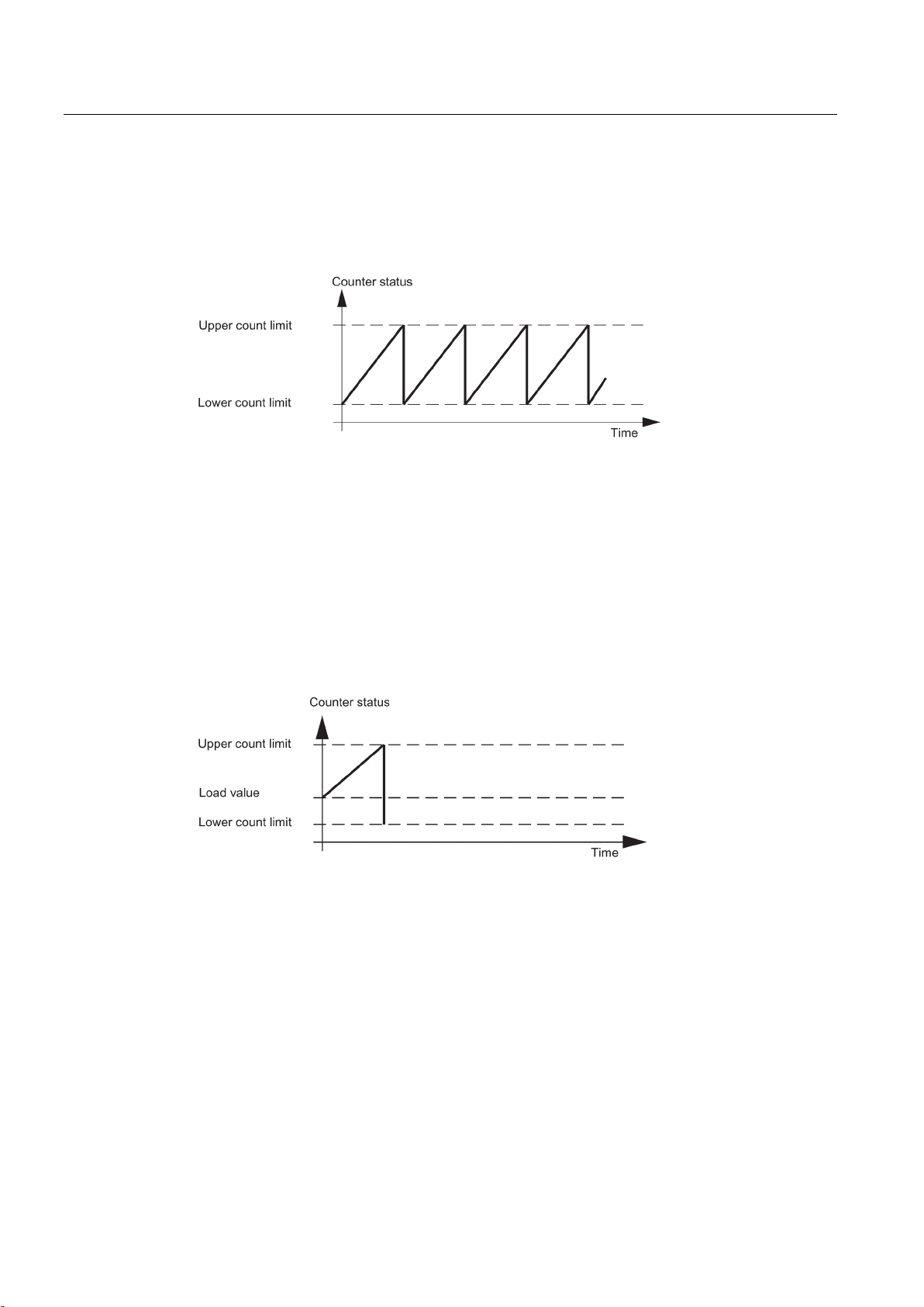
Continuous counting
Single counting
2.2 Gate functions
If when counting in the up direction a counter has reached the high count limit and a further
count pulse comes, then the counter jumps to the low count limit and begins to total the
count pulses; thus, it counts continuously.
Figure 2-1 Continuous counting in the up direction
If when counting in the down direction a counter has reached the low count limit and a
further count pulse comes, then it jumps to the high count limit and then goes on counting
down from there.
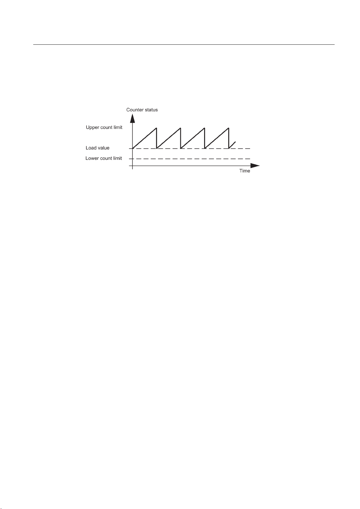
For single counting the counter starts from the load value. If when counting up a counter has
reached the high count limit and a further count pulse comes, then the counter jumps to the
low count limit and comes to a halt even if further count pulses come.
Figure 2-2 Single counting in the up direction
If when counting down a counter has reached the low count limit and a further count pulse
comes, then the counter jumps to the high count limit and comes to a halt even if further
count pulses come.
Counter module FM 450-1
20 Manual, 02/2014, A5E03648739-02
This is how the FM 450-1 counts
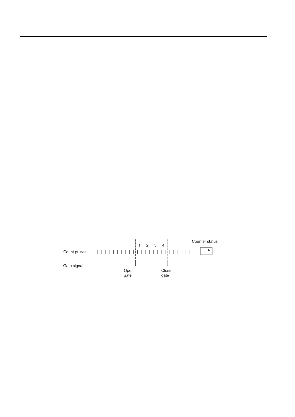
Periodic counting
2.1 Basics
For periodic counting the respective counter starts from the load value. If when counting up
the counter reaches the high count limit and further count pulses come, then the counter
jumps to the load value and starts totalizing the count pulses.
Figure 2-3 Periodic counting in the up direction
If when counting down a counter has reached the low count limit and a further count pulse
comes, then the counter jumps to the load value and then continues counting down from
there.
Counter module FM 450-1
Manual, 02/2014, A5E03648739-02
21
This is how the FM 450-1 counts
2.2
Gate functions
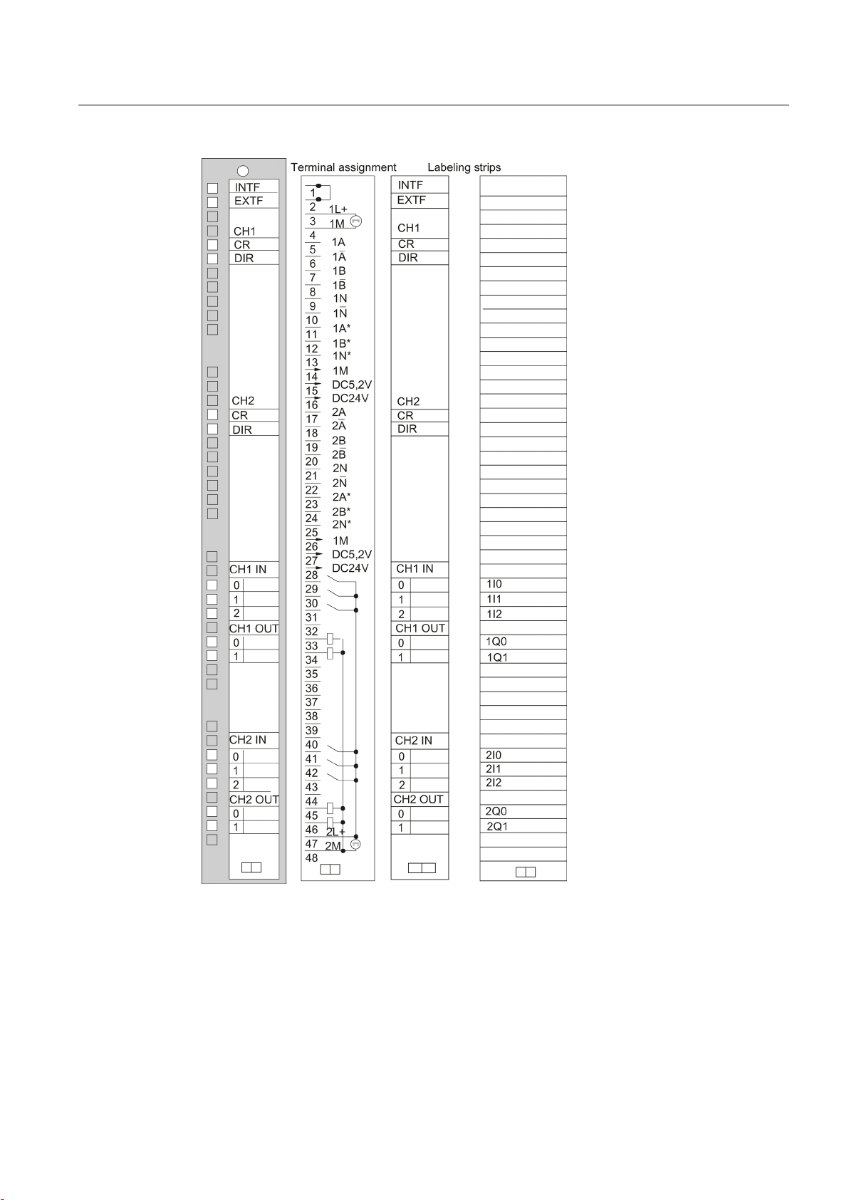
Counting with gate functions
Software gate and hardware gate
Example
Ending counting process with the gate stop function
2.2 Gate functions
Many applications require that the counting process should be started or stopped at a
specifically defined point in time, depending on other events. In the case of the FM 450-1
starting and stopping the counting process like this take place via a gate function. If the gate
is opened, count pulses can reach a counter and the counting process is started. If the gate
is closed, count pulses can no longer reach the counter and the counting process is stopped.
The module possesses two gate functions for each counter:
● A software gate (SW gate) which is controlled via the user program in the CPU.
● A hardware gate (HW gate) that is controlled via the 1I0 and 1I1 (counter 1) and/or 2I0
and 2I1 (counter 2) digital inputs on the module. When assigning parameters for the FM
450-1 you determine if the operation of the hardware gate is to be level controlled or edge
controlled.
When the gate signal is set, the gate is opened and the count pulses are counted. If the gate
signal is taken away, the gate is closed and the count pulses are no longer picked up by the
counter. The counter status remains constant.
The figure shows a gate opening and closing and the pulses being counted:
Figure 2-4 Opening and closing a gate
You can end the counting process when counting with the SW gate and when counting with
the HW gate with the respective gate stop function. For this purpose you set the GATE_STP
input parameter of the FC CNT_CTRL.
Counter module FM 450-1
22 Manual, 02/2014, A5E03648739-02

3
3.1
Chapter overview
Overview
In this chapter you will find information on the installation and removal of the FM 450-1
● You will find out what you have to pay attention to during installation. You will obtain
information on project planning and on the design of an FM 450-1
● Step by step you will be shown how to install and remove the FM 450-1.
Counter module FM 450-1
Manual, 02/2014, A5E03648739-02
23

Installation and Removal
3.2
Preparing for Mounting
Important safety rules
Defining the slots
Designing the mechanical structure
Define start address
3.4 Removal of the FM 450-1
There are important rules to be observed when integrating an S7-400 with an FM 450-1 into
a plant or a system.
These rules and regulations are explained in manual /1/.
The FM 450-1 function module can be installed like a signal module in any central device or
extension device.
Manual /1/ provides you with information on how the mechanical structure can be designed
and how to proceed.
The start address of the FM 450-1 is required for the purpose of communication between the
CPU and the FM 450-1. The start address is entered into the DB of the FC CNT_CTRL (refer
to chapter "Program (Page 45)" and chapter "Assignment of the DB (Page 103)"). The entry
is either made with the program editor or out of the user program.
You specify the start address for the module under STEP 7.
Counter module FM 450-1
24 Manual, 02/2014, A5E03648739-02

Installation and Removal
3.3
Installing the FM 450-1
Rules
Tools required
Installation procedure
Further information
3.3 Installing the FM 450-1
No special protective measures (EGB guidelines) are required for installing the FM 450-1.
You require a 4.5 mm screwdriver to install the FM 450-1.
Proceed as follows to install an FM 450-1
1. Hook the FM 450-1 in at the top and rotate it down.
2. Screw the FM 450-1 tight (torque approx. 0.8 to 1.1 Nm).
3. Label the FM 450-1 with its slot number. For this purpose use the number wheel enclosed
with the rack.
Further information on the installation and removal of modules is to be found in manual /1/.
The system according to which you must perform then numbering and the procedure for
defining the slot number are described in manual /1/.
Counter module FM 450-1
Manual, 02/2014, A5E03648739-02
25

Installation and Removal
3.4
Removal of the FM 450-1
Rules
Tools required
Procedure for removal
Further information
3.4 Removal of the FM 450-1
No special protective measures (EGB guidelines) are required for removing the FM 450-1.
You require a 4.5 mm screwdriver to remove the FM 450-1.
Proceed as follows to remove an FM 450-1
1. Release the front connector and pull it out.
2. Undo the module fixing screw.
3. Rotate the module out of the rack and unhook it.
4. If necessary, install a new module.
Further information on the installation and removal of modules is to be found in manual /1/.
Counter module FM 450-1
26 Manual, 02/2014, A5E03648739-02

4
4.1
Chapter overview
Chapter overview
In this chapter you will find information on wiring the FM 450-1
● Terminal assignment of the front connector.
● Terminal functions.
● Notes on the selection of cables.
● Procedure when wiring the front connector.
● State of module after it has been wired and the power supply is switched on.
Counter module FM 450-1
Manual, 02/2014, A5E03648739-02
27

Wiring
4.2
Terminal assignment of the front connector
Front connectors
4.4 Module status after power is switched on
You connect the following to the 48-pin front connector:
● count signals,
● digital inputs
● digital outputs
● encoder power supply
● auxiliary voltage and load voltage.
The following illustration shows the front side of the front connector, the strip with the
terminal assignment printed on and the labeling strips.
Counter module FM 450-1
28 Manual, 02/2014, A5E03648739-02
Wiring
4.4 Module status after power is switched on
Figure 4-1 Front connector of the FM 450-1
Counter module FM 450-1
Manual, 02/2014, A5E03648739-02
29

Wiring
Assignment of front connector
Terminal
Name
Inputs/
outputs
Function
5 V encoder RS
422, symmetrical
24 V encoder,
asymmetric
24-V pulse
encoder with
direction level
24 V initiator
1 - 2
-
3
1L+
ON
24 V auxiliary voltage supply for encoders
4
1M
ON
Auxiliary voltage ground to supply encoders
Counter 1
5
1 A
ON
Encoder signal A
-
6
1 /A
ON
Encoder signal /A
-
7
1 B
ON
Encoder signal B
-
8
1 /B
ON
Encoder signal /B
-
9
1 N
ON
Encoder signal N
-
10
1 /N
ON
Encoder signal /N
-
11
1 A*
ON
-
Encoder signal A*
12
1 B*
ON - Encoder signal B*
Directional signal
-
13
1 N*
ON - Encoder signal N*
-
14
1M
OFF
Ground for encoder power supply
16
24 VDC
OFF
-
24 V encoder power supply
Counter 2
17
2 A
ON
Encoder signal A
-
18
2 /A
ON
Encoder signal /A
-
19
2 B
ON
Encoder signal B
-
20
2 /B
ON
Encoder signal /B
-
21
2 N
ON
Encoder signal N
-
22
2 /N
ON
Encoder signal /N
-
23
2 A*
ON
-
Encoder signal A*
24
2 B*
ON
-
Encoder signal B*, directional signal
25
2 N*
ON
-
Encoder signal N*
26
1M
OFF
Ground for encoder power supply
power supply
28
24 VDC
OFF
-
24 V encoder power supply
4.4 Module status after power is switched on
Table 4- 1 Assignment of front connector
15 5.2 VDC OFF 5.2 V encoder
power supply
27 5,2 VDC OFF 5,2 V encoder
-
-
Counter module FM 450-1
30 Manual, 02/2014, A5E03648739-02
 Loading...