

Page 1

Application for Control Technology
SIMATIC S7 CPU 300/400
Application Description
Time switch based on the S7-300/400 CPUs with simple HMI
system including radio-controlled clock connection
Page 2

Time switch based on the S7-300/400 CPUs with simple HMI system
including radio-controlled clock connection
Warranty, Liability and Support
We accept no liability for information contained in this document.
We do not accept liability, whatever the legal basis, for any damages
arising from the use of examples, notes, programs, configuration and
performance data etc. described in this document, except where we are
obliged to by the German Product Liability Act or in cases of willful damage
or gross negligence, injury to life, body or health, breach of guarantee for
the condition of products or items assumed by us, fraudulent concealment
of a defect or breach of a substantial contractual obligation. However,
claims arising from a breach of a condition which goes to the root of the
contract shall be limited to the foreseeable damage which is intrinsic to the
contract, unless caused by intent or gross negligence or based on
mandatory liability for injury of life, body or health. The above conditions are
not meant to change the burden of proof to the detriment of the user.
Copyright © Siemens AG 2005 All rights reserved
BID21669756_Zeitschaltuhr_einfach_DOKU_v20_e.doc
The application examples do not purport to cover all details or variations in
equipment, nor do they provide for every possible contingency. They are
not customer-specific solutions. They are only intended to provide support
for typical tasks. You are responsible for ensuring that the described
products are used correctly. These application examples do not relieve you
of the responsibility to use sound practices in application, installation,
operation and maintenance. By using this application example you accept
that Siemens is not liable for any damages except for those specified in the
above liability clause. We reserve the right to make changes in these
application examples at any time without prior notice. If there are any
deviations between the recommendations provided in this application
example and other Siemens publications – e.g. Catalogs – the contents of
the other documents have priority.
Copyright© 2005 Siemens A&D. Any form of duplication or
distribution of these application examples or excerpts hereof is
prohibited without the expressed consent of Siemens Energy &
Automation, Inc.
For questions about this document please use the following e-mail address:
mailto:csweb@ad.siemens.de
Rev. B - final 19.07.2002 2/84
Page 3
Warranty, Liability and Support
Time switch based on the S7-300/400 CPUs with simple HMI system
including radio-controlled clock connection
Foreword
Structure of the document
The documentation of this application is divided into the following main
parts.
Dokument-Eigenschaft. All rights reserved
BID21669756_Zeitschaltuhr_einfach_DOKU_v20_e.doc
Copyright © Siemens AG Fehler! Unbekannter Name für
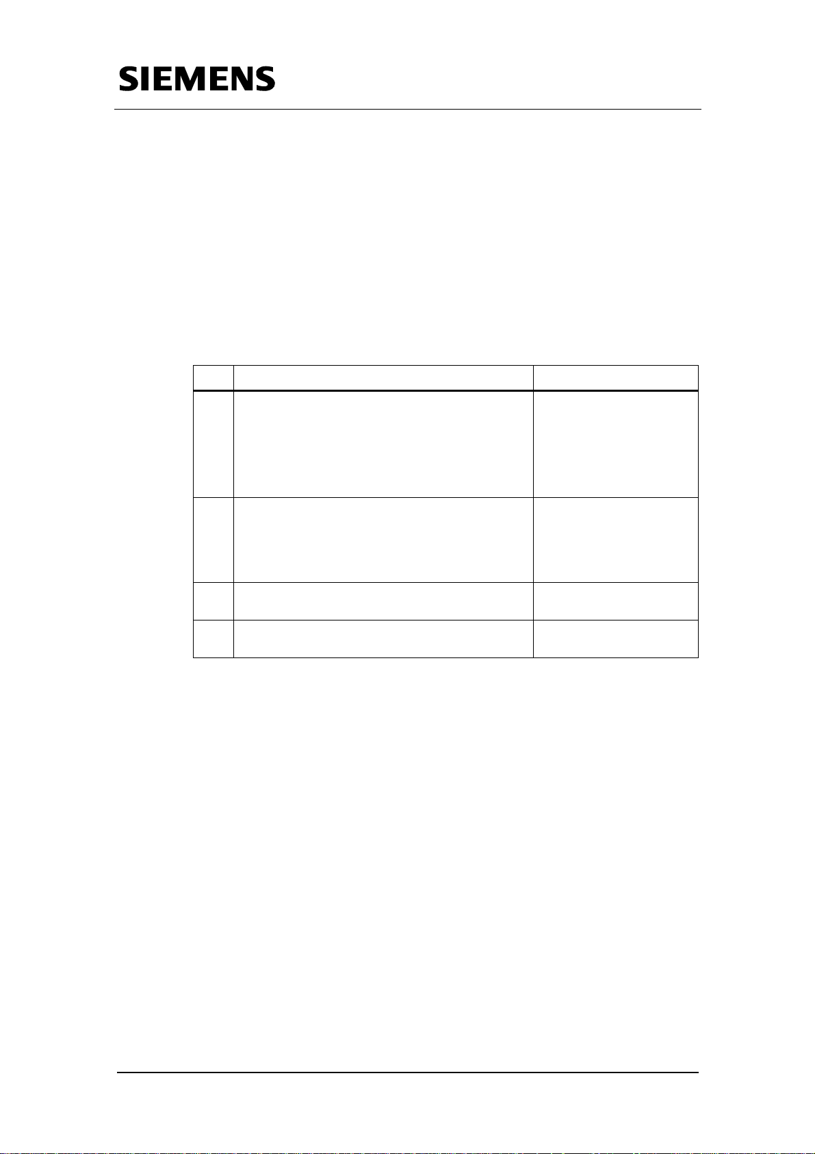
Part Description
Part A1 gives you a general overview of the
A1
contents. You will learn about the components
used (standard hardware and software and
newly developed software).
The basic function data illustrate the powerful
performance of this application.
Part A2 gives you a detailed description of the
A2
function processes of the hardware and
software components. Read this part if you
want to know what the functions do and how
the solution components interact.
Part B takes you step by step through
B
installation and start-up of the application.
Part C is of interest if you want to take the
C
software and expand or adapt it to your set-up.
Note
You can skip this part if
you only want to test the
application using step-bystep instructions.
Rev. B - final 19.07.2002 3/84
Page 4

Warranty, Liability and Support
Time switch based on the S7-300/400 CPUs with simple HMI system
including radio-controlled clock connection
Table of Contents
Part A1 : Application Description................................................................................ 7
1 Illustrate the performance of the entire applicationThe Automation
Problem - An Overview..............................................................................
8
2 Automation Solution .................................................................................... 12
2.1 Functionality in the S7-CPU............................................................................ 15
2.1.1 Absolute time switching functions...................................................................15
2.1.2 Relative time function ..................................................................................... 16
2.1.3 Additional functions......................................................................................... 16
2.2 Controlling and monitoring..............................................................................18
2.3 Standard components required ...................................................................... 21
2.3.1 Hardware components.................................................................................... 21
2.3.2 Software components..................................................................................... 21
2.4 Application software components required and their "product features" ........ 23
2.5 Installation with simple setup.......................................................................... 25
Dokument-Eigenschaft. All rights reserved
BID21669756_Zeitschaltuhr_einfach_DOKU_v20_e.doc
Copyright © Siemens AG Fehler! Unbekannter Name für
3 Basic performance data............................................................................... 26
Part A2 : Function Mechanisms................................................................................27
4 Examples of Function Mechanisms............................................................ 28
4.1 Introduction..................................................................................................... 28
4.2 Overview of the Structure Elements ...............................................................28
4.3 STEP7 application level..................................................................................29
1.1.1 Absolute time switching functions...................................................................30
4.3.1 One-day time switch.......................................................................................31
4.3.2 Seven-day time switch....................................................................................32
4.3.3 One-month time switch................................................................................... 33
4.3.4 One-year time switch...................................................................................... 34
4.3.5 Relative time switch........................................................................................ 35
4.3.6 Additional functions......................................................................................... 38
Summer/wintertime changeover ................................................................ 38
Holiday recognition..................................................................................... 40
4.4 HMI System....................................................................................................41
4.4.1 Operation at the OP3......................................................................................41
1.1.2 Operation at the TP170A................................................................................ 43
Part B: Installation of the Sample Application.........................................................46
5 Installation of Hardware and Software ....................................................... 47
5.1 Hardware configuration................................................................................... 47
5.2 Software installation........................................................................................ 49
5.2.1 Loading the application software into the S7-CPU.........................................49
Rev. B - final 19.07.2002 4/84
Page 5

Warranty, Liability and Support
Time switch based on the S7-300/400 CPUs with simple HMI system
including radio-controlled clock connection
5.2.2 Load the application software into the panel .................................................. 51
6 Using the Application................................................................................... 54
6.1 Application case 1: Many time switches........................................................54
6.2 Application case 2: Pulse chain..................................................................... 63
Part C: Program Description ..................................................................................... 70
7 STEP 7 Program............................................................................................ 71
7.1 Absolute time switches...................................................................................71
7.1.1 Seven-day time switch....................................................................................71
7.1.2 One-month time switch................................................................................... 71
7.2 Relative time switch........................................................................................ 73
1.2 Special functions............................................................................................. 74
7.2.1 Summer/wintertime changeover.....................................................................74
7.2.2 Holidays/special days..................................................................................... 75
Dokument-Eigenschaft. All rights reserved
BID21669756_Zeitschaltuhr_einfach_DOKU_v20_e.doc
Copyright © Siemens AG Fehler! Unbekannter Name für
8 HMI Interface ................................................................................................. 77
9 Changes in the STEP 7 Programs............................................................... 77
9.1 What to do if a second time switch of the same type is needed?................... 77
9.2 How can I get several switch-on/off times into one time switch block?........... 78
9.3 What to do if more holidays or special days are needed?.............................. 79
9.4 How can I save on Instance DBs?..................................................................80
Appendix: Connection of the SICLOCK radio clock ............................................... 81
Rev. B - final 19.07.2002 5/84
Page 6
A
Warranty, Liability and Support
Time switch based on the S7-300/400 CPUs with simple HMI system
including radio-controlled clock connection
Preamble
Many systems in automation technology (e.g. in the field of Heating,
Ventilation & Air Conditioning) require a control dependent on time of the
day and day of the week. Apart from the time dependent control of certain
processes, a monitoring and control function is also necessary for these
time switch functions.
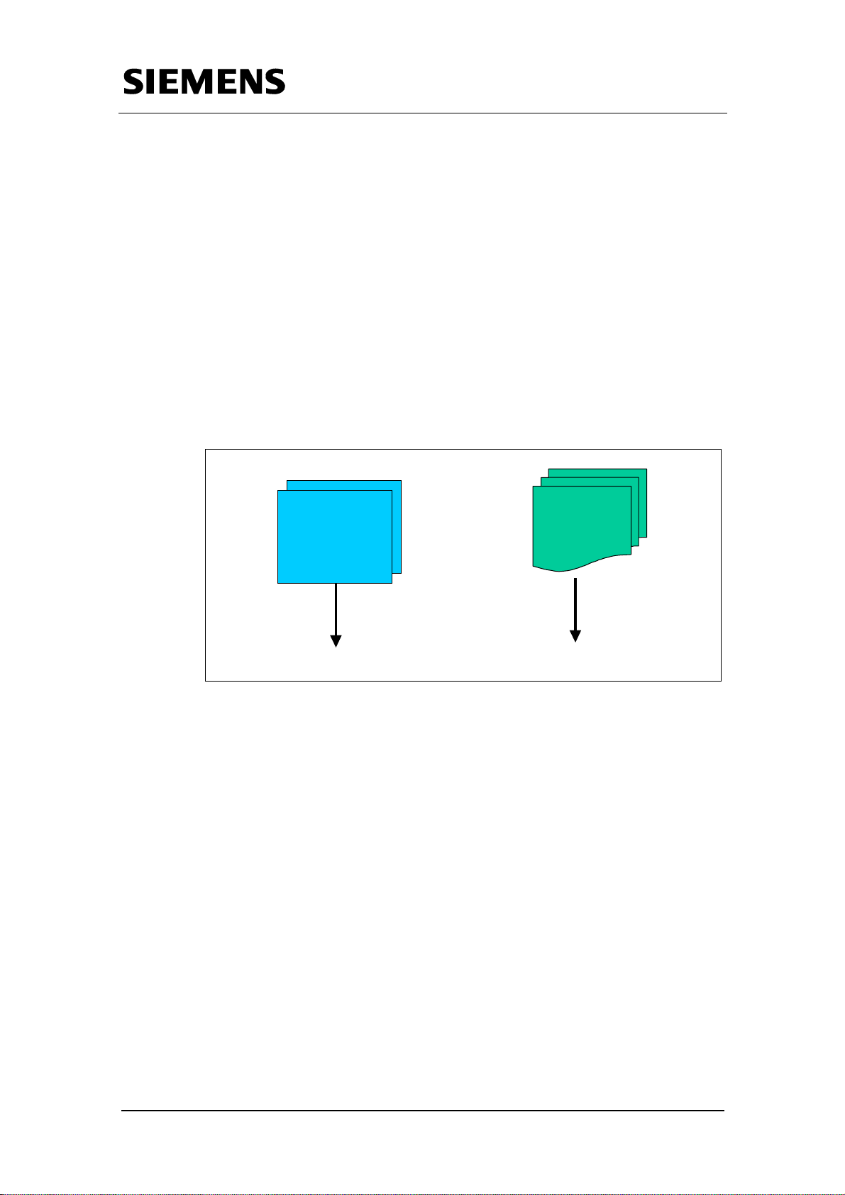
We take an everyday automation problem (see chapter 1) and present all
required solution elements individually. The solution consists of standard
SIMATIC components plus the software blocks developed especially for
this application. The blocks are designed so that they can be used directly
for concrete problems or they can be adjusted to an individual task by
simple expansion/reduction.
Dokument-Eigenschaft. All rights reserved
BID21669756_Zeitschaltuhr_einfach_DOKU_v20_e.doc
Copyright © Siemens AG Fehler! Unbekannter Name für
SIMATIC
Standard
+
pplikatio n
software
components
... Provid ed by you
This application offers a convenient and quick way to implement the "Time
switch" key function. A HMI interface is provided allowing the operator to
control the application.
... Delive re d with th e a pplicatio n
Rev. B - final 19.07.2002 6/84
Page 7

Warranty, Liability and Support
Time switch based on the S7-300/400 CPUs with simple HMI system
including radio-controlled clock connection
Part A1 : Application Description
Objectives of Part A1
Part A1 of this document provides the reader with information on the
following topics:
• Pinpoint the automation problem
• Design a possible solution
Dokument-Eigenschaft. All rights reserved
BID21669756_Zeitschaltuhr_einfach_DOKU_v20_e.doc
Copyright © Siemens AG Fehler! Unbekannter Name für
Rev. B - final 19.07.2002 7/84
Page 8
Warranty, Liability and Support
Time switch based on the S7-300/400 CPUs with simple HMI system
including radio-controlled clock connection
1 Illustrate the performance of the entire applicationThe
Automation Problem - An Overview
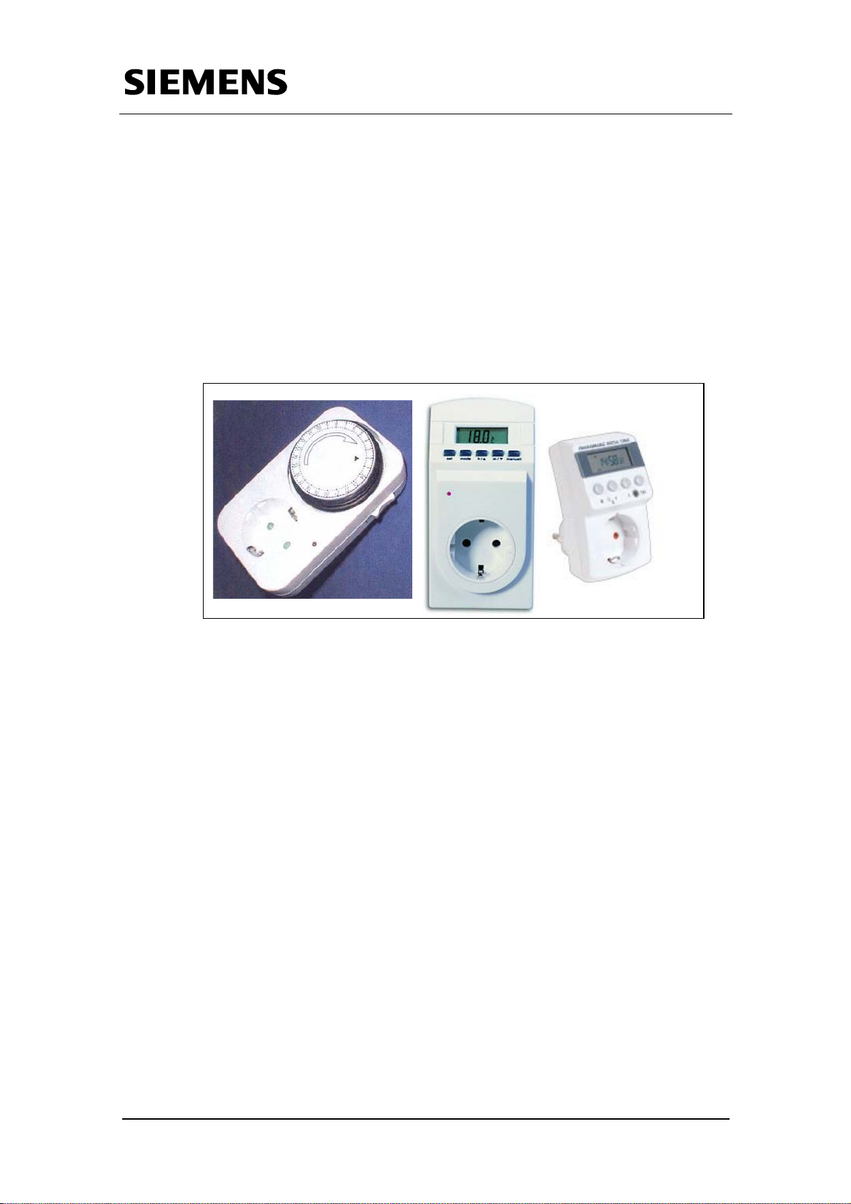
Precise time tuning is necessary in many fields. Even in household
technology for example, systems must work dependent on time of the day
or day of the week. One possible solution for this problem are electrical and
mechanical time switches. The following figure shows examples for
electrical time switches:
Dokument-Eigenschaft. All rights reserved
BID21669756_Zeitschaltuhr_einfach_DOKU_v20_e.doc
Copyright © Siemens AG Fehler! Unbekannter Name für
Fig. 1-1 Examples of time switches
These are all hardware clocks which enable solving the time switching
problem for example in the field of household technology. These clocks are
readily available in many DIY superstores. Operating the devices is so
simple that a layperson can use this clock easily.
Apart from these “primitive applications”, time-dependent controls are also
required in large areas of automation technology. Some “professional
applications” are illustrated in the following table.
Rev. B - final 19.07.2002 8/84
Page 9

Warranty, Liability and Support
Time switch based on the S7-300/400 CPUs with simple HMI system
including radio-controlled clock connection
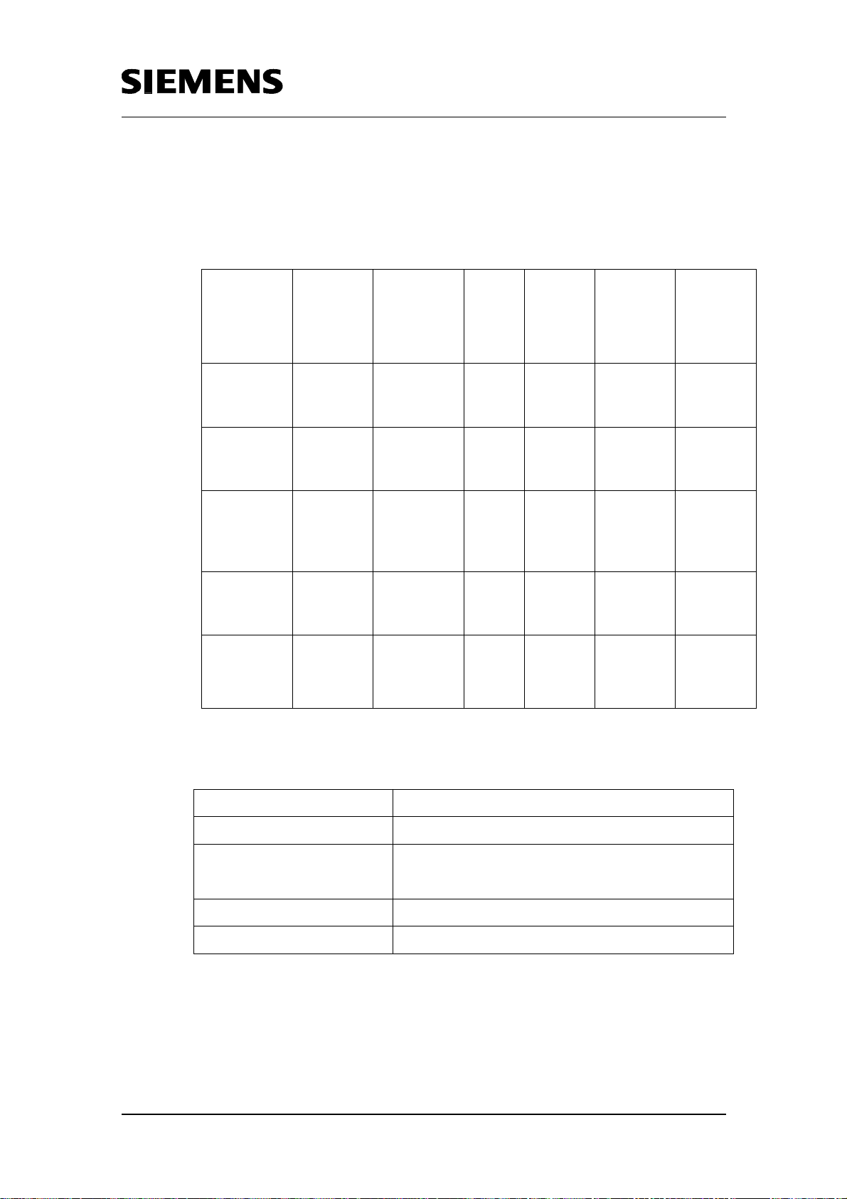
Table 1-1 Application examples for professional time switches
Application Illustration
Greenhouse control:
Watering and lighting systems of a greenhouse must
be controlled.
Lighting control:
Lighting systems are automatically controlled in
residential homes or hotels.
Dokument-Eigenschaft. All rights reserved
BID21669756_Zeitschaltuhr_einfach_DOKU_v20_e.doc
Copyright © Siemens AG Fehler! Unbekannter Name für
Pump control:
Pumps for heating of service water are automatically
controlled in residential homes.
Automatic feeding machine:
Animals in a stable can be fed via automatic feeding
machines. Similar feeding machines are also available
for example for aquariums.
Many industrial applications in the field of automation technology also
require exact switching of processes. The problem is illustrated below:
Rev. B - final 19.07.2002 9/84
Page 10
Warranty, Liability and Support
Time switch based on the S7-300/400 CPUs with simple HMI system
including radio-controlled clock connection
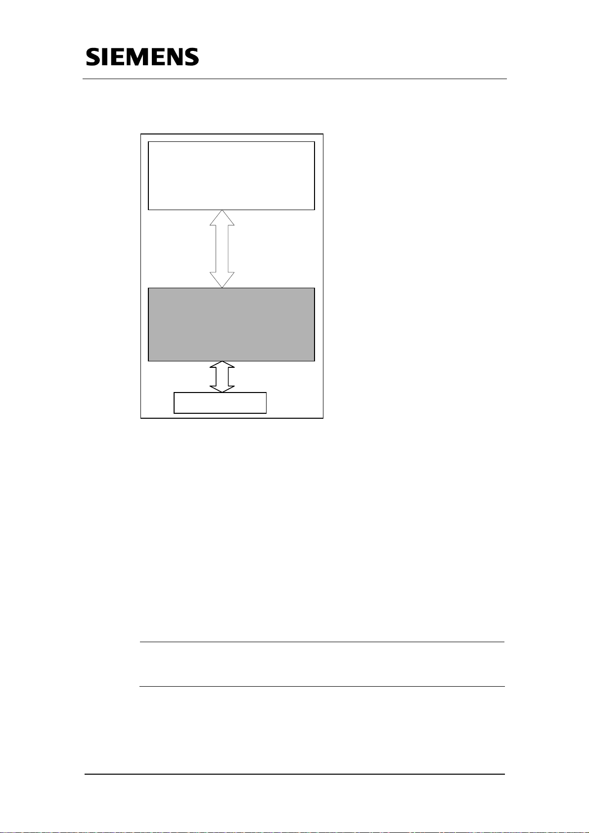
Monitoring and
Control unit
S7-CPU
Protocol
services
User program
Process area
Fig. 1-2 Problem layout for automation technology
Dokument-Eigenschaft. All rights reserved
BID21669756_Zeitschaltuhr_einfach_DOKU_v20_e.doc
Copyright © Siemens AG Fehler! Unbekannter Name für
A block in the S7-CPU, which sets an output dependent of absolute time or
which after a certain event lets a parameterized length of time pass, is
required for the temporal design of these or similar processes.
The absolute switch-on and switch-off times for these processes must be
configurable at a HMI system and subsequently be available in the S7CPU. Furthermore, it should be possible to parameterize a certain length of
time which will pass dependent on a start event (relative time).
The S7-CPU and the HMI system are connected via MPI.
In our example the absolute switch-on and switch-off times are entered at
the HMI system and subsequently compared with the absolute system time
of the S7-CPU.
Note
The block principally also functions without HMI interface. Parameterization can be
made directly at the input parameters.
Additionaly, the possibility of optionally connecting a radio-controlled clock
to the automation system should be offered. This clock is supposed to
synchronize the system time with the official time and to conduct the
changeover from summer time to winter time and the other way round.
Rev. B - final 19.07.2002 10/84
Page 11

Warranty, Liability and Support
Time switch based on the S7-300/400 CPUs with simple HMI system
including radio-controlled clock connection
This application was realized with the SIPLUS radio clock. Alternatively the
SICLOCK radio clock can be used. This alternative is dealt with in detail in
the appendix.
In case you do not want to use a radio-controlled clock the summer/ winter
time changeover is automatically conducted at the officially fixed dates by a
special function block which is delivered with this application. In this case
the system time can certainly not be synchronized with the official time.
Basic data of the requirement
The requirements by the automation problem on the S7-CPU and the HMI
interface are listed below:
Dokument-Eigenschaft. All rights reserved
BID21669756_Zeitschaltuhr_einfach_DOKU_v20_e.doc
Copyright © Siemens AG Fehler! Unbekannter Name für
S7 CPU
• There are the following blocks:
- One-day, seven-day, one-month, one-year time switches
- Relative time switch
- Summer/wintertime changeover
- Holiday recognition
- Connection with radio-controlled clock
• Respectively one switch-on and one switch-off time can be
parameterized for the time switches (one-day, seven-day, one-month,
one-year and relative time switch).
• Resetting the time switches must be simple.
HMI Interface
User interface for the application for
• Input for current switch-on and switch-off times
• Controlling the sample application:
Starting / resetting time switches
• Display of current time switch status (on/off)
• Button for selecting mode of summer / winter time changeover: via radio-
controlled clock or via function block (delivered with the application)
Rev. B - final 19.07.2002 11/84
Page 12
Warranty, Liability and Support
Time switch based on the S7-300/400 CPUs with simple HMI system
including radio-controlled clock connection
2 Automation Solution
The automation problem described in chapter 1 can be solved with
standard hardware and software components (SIEMENS) plus the user's
own customized software.
The SIMATIC S7, together with a monitoring and control unit (SIMATIC
OP/TP), is useful for executing the automation task.
Based on the used standard HW/SW components, as well as the compiled
application software, data are exchanged between S7-CPU and HMI
system via an MPI bus system.
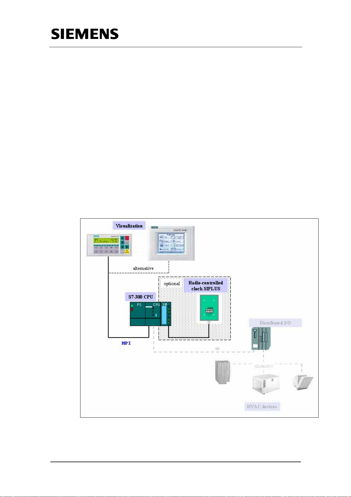
Both the diagrams below give you an overview of all the components
involved. Figure 2-1 shows you the standard components. Connecting the
HVAC devices to the S7-CPU via the distributed I/O was not looked into in
this application, and is thus only outlined schematically. Figure 2-2 shows
you the user software developed for this application.
Dokument-Eigenschaft. All rights reserved
BID21669756_Zeitschaltuhr_einfach_DOKU_v20_e.doc
Copyright © Siemens AG Fehler! Unbekannter Name für
Fig. 2-1 Standard hardware components
Rev. B - final 19.07.2002 12/84
Page 13

Warranty, Liability and Support
Time switch based on the S7-300/400 CPUs with simple HMI system
including radio-controlled clock connection
Diagram of user software running on the standard components
Dokument-Eigenschaft. All rights reserved
BID21669756_Zeitschaltuhr_einfach_DOKU_v20_e.doc
Copyright © Siemens AG Fehler! Unbekannter Name für
Fig. 2-2 User software
Description of the complete solution
Solving the task described in chapter 1 requires several blocks (see
Chapter 2.1) for time-dependent setting or resetting of an output. In our
solution the block parameter are input via an HMI-system (see
Chapter 2.2).
However, the parameters can also be input directly at the block.
The application contains function blocks for absolute and relative time
switch functions (clocks). Each clock has only one setting option
(corresponding to a “cam”), i.e. only respectively one switch-on and one
switch-off time can be entered at a block. This way of handling has many
advantages:
• The function blocks are kept very fine-granular. This enables ideal usage
of the storage requirements of the S7-CPU.
• Flexible application of the blocks.
• Simple parameterization of the blocks.
Rev. B - final 19.07.2002 13/84
Page 14
Warranty, Liability and Support
Time switch based on the S7-300/400 CPUs with simple HMI system
including radio-controlled clock connection
Furthermore, the application contains additional functions such as
summer/winter time changeover as well as taking holidays into
consideration.
The additional function „Summer/winter time changeover“ is conducted by
default by the FB103 „summer_winter“. Optionally this changeover can also
be controlled by means of a radio-controlled clock. In this case a digital
input module is necessary (i.e. SM321), as two digital inputs are required in
order to receive the data sent from the clock module.
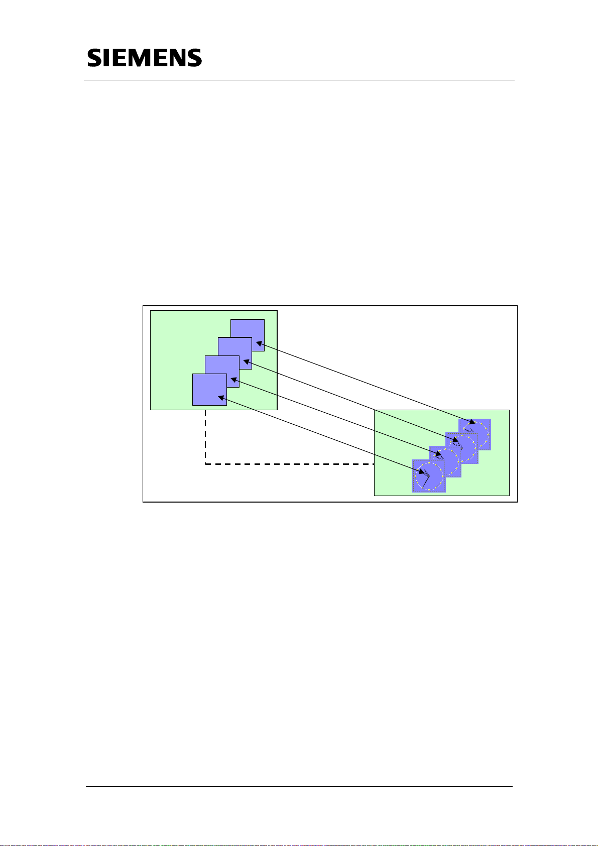
For each absolute or relative clock (corresponds to a function call of a
function block) a view is used in the HMI system.
Dokument-Eigenschaft. All rights reserved
BID21669756_Zeitschaltuhr_einfach_DOKU_v20_e.doc
Copyright © Siemens AG Fehler! Unbekannter Name für
HMI System
View 1
Fig. 2-3 Function scheme
View 4
View 3
View 2
S7-CPU
Rev. B - final 19.07.2002 14/84
Page 15
t
t
d
Warranty, Liability and Support
Time switch based on the S7-300/400 CPUs with simple HMI system
including radio-controlled clock connection
2.1 Functionality in the S7-CPU
The following blocks are available in the S7-CPU:
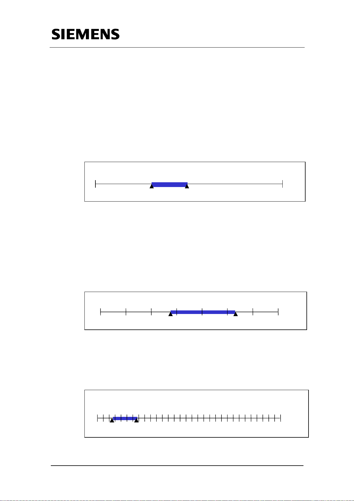
2.1.1 Absolute time switching functions One-day time switch:
This block can detect a time range within 24 hours, e.g. 8 to 12 o‘clock.
These switch times are repeated daily.
Dokument-Eigenschaft. All rights reserved
BID21669756_Zeitschaltuhr_einfach_DOKU_v20_e.doc
Copyright © Siemens AG Fehler! Unbekannter Name für
12:00 a.m
11:59:59 p.m
8:00 a.m. 12:00 p.m.
Fig. 2-4 Time range one-day time switch
Seven-day time switch:
This block can detect a time range within 7 days, e.g. each Tuesday
from 8 o’clock p.m. to Friday 6 o‘clock a.m.. These switch times are
repeated on a weekly basis.
Note:
It is also possible to repeat a switch time daily from Monday to Friday.
So 12:00 a.m. Sa 11:59:59 p.m.
Di, 8:00 p.m.
Fr, 6:00 a.m.
Fig 2-5 Time range seven-day time switch
One-month time switch:
This block can detect a time range within 31 days, e.g. each month from
rd
the 3
r
3
, 12 o’clock p.m. to the 7th 21 o‘clock p.m..
s
1
12:00 a.m.
, 12:00 p.m. 7th , 9:00 p.m.
s
31
11:59:59 p.m.
Fig 2-6 Time range one-month time switch
Rev. B - final 19.07.2002 15/84
Page 16
t
:00 a.m.
t
h
h
Warranty, Liability and Support
Time switch based on the S7-300/400 CPUs with simple HMI system
including radio-controlled clock connection
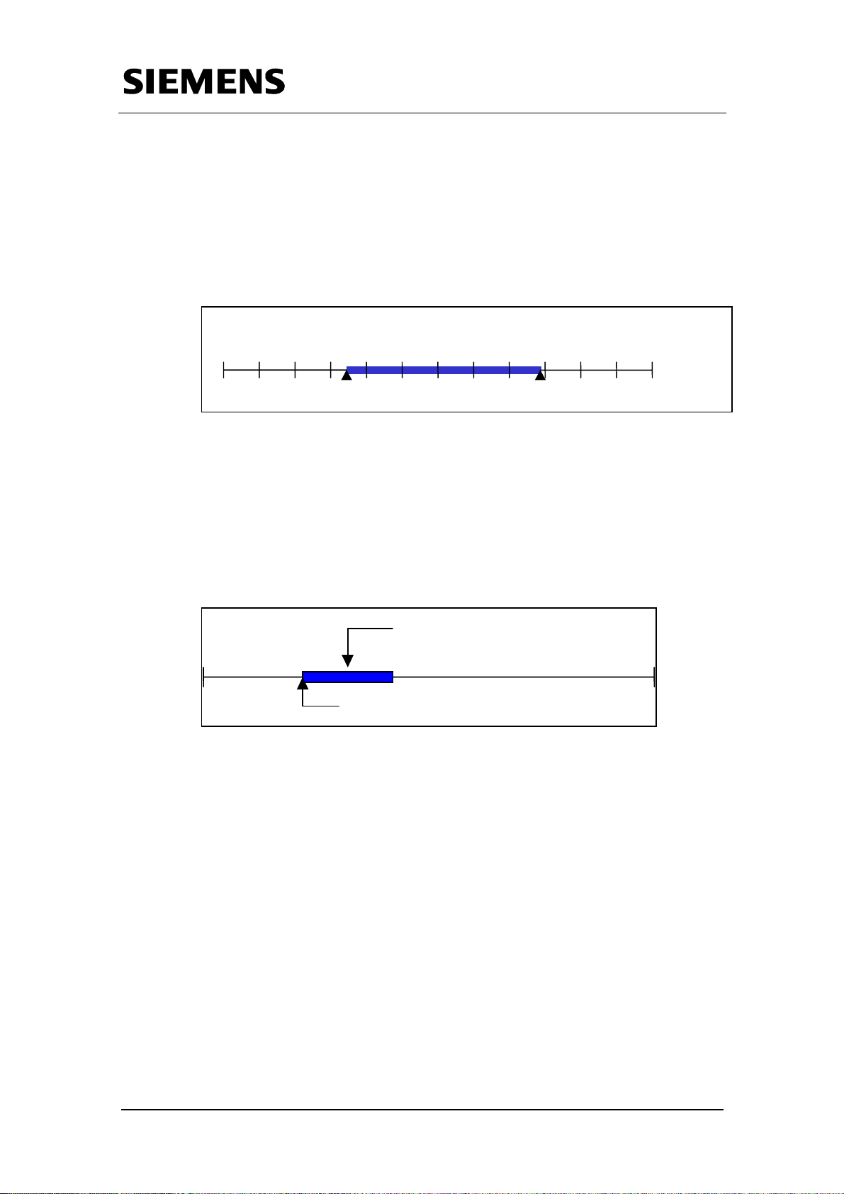
One-year time switch
This block can detect a time range within 365 days, e.g. from April 13
8 o’clock a.m. to September 28
s
1
Jan.
12
t
13
May, 8:00 28
Fig 2-7 Time range one-year time switch
2.1.2 Relative time function Relative time switch:
The clock is activated on a start signal and remains active until the
parameterized time interval has elapsed.
th
12 o‘clock p.m..
t
Sept, 12:00
Parameterized time
(e.g.: 3 hours)
th
s
31
Dec.
11:59:59 p.m.
Dokument-Eigenschaft. All rights reserved
BID21669756_Zeitschaltuhr_einfach_DOKU_v20_e.doc
Copyright © Siemens AG Fehler! Unbekannter Name für
Start signal
Fig. 2-8 Relative time switch
2.1.3 Additional functions
• Summer/wintertime changeover:
The clock changes the absolute system time in the S7-CPU by plus or
minus one hour, depending on whether the time changeover is from
winter to summer time, or from summer to winter time.
For this changeover there are two alternatives:
1. Radio-controlled changeover (for this alternative you have to use the
radio-controlled clock shown in figure 2-1):
The system time is being synchronized after the clock connected to
the system has sent the changeover signal.
Rev. B - final 19.07.2002 16/84
Page 17

Warranty, Liability and Support
Time switch based on the S7-300/400 CPUs with simple HMI system
including radio-controlled clock connection
2. Program controlled changeover:
The system time is being adjusted at the officially fixed dates by
means of a function block which is included in this application.
• Holiday/special day recognition:
Data for holidays and special days are stored in a DB in the format
day/month/year. The block checks whether a day in this DB coincides
with this current date, and sets an output to 1. Otherwise, the output is 0.
Dokument-Eigenschaft. All rights reserved
BID21669756_Zeitschaltuhr_einfach_DOKU_v20_e.doc
Copyright © Siemens AG Fehler! Unbekannter Name für
Rev. B - final 19.07.2002 17/84
Page 18
Warranty, Liability and Support
Time switch based on the S7-300/400 CPUs with simple HMI system
including radio-controlled clock connection
2.2 Controlling and monitoring
The HMI system used in this case is an OP3 or alternatively a TP170A.
Only a short overview is given here on operation. A detailed description on
operation is given in Chapter 6.
The HMI page contains a view on each block in the S7-CPU. Inputs for the
respective block are made via this view. The variables in the HMI system
are connected with the correct memory space in the S7-CPU, so that inputs
are at the correct location and can be evaluated in the S7 program.
Note
Information on setting the time in the HMI system via the S7-CPU or for setting the
S7-clock via the HMI system are given on the
[ProductSupportPages] under Entry ID 944136 (OP3) or Entry ID 2383397
(TP170A).
ProduktSupportSeiten
Dokument-Eigenschaft. All rights reserved
BID21669756_Zeitschaltuhr_einfach_DOKU_v20_e.doc
Copyright © Siemens AG Fehler! Unbekannter Name für
Rev. B - final 19.07.2002 18/84
Page 19
p
Warranty, Liability and Support
Time switch based on the S7-300/400 CPUs with simple HMI system
including radio-controlled clock connection
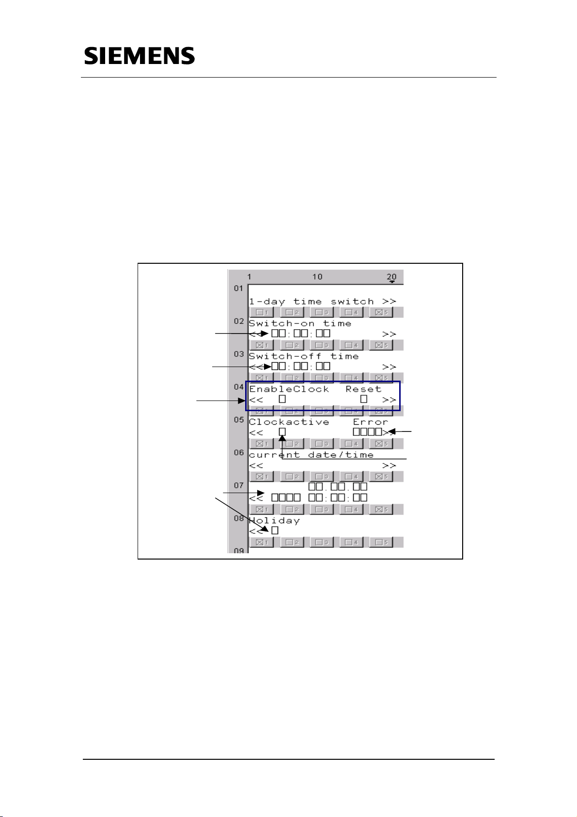
HMI with OP3
The OP3 is a text-based display of the lower performance range. A
maximum of 2 lines at 20 characters each can be operated and monitored
at once on the device.
An example (one-day time switch) of the HMI interface at OP3 is illustrated
below.
The upper section of the illustration gives the input parameter, the lower
section the output parameter.
Switch-o n tim e
Dokument-Eigenschaft. All rights reserved
BID21669756_Zeitschaltuhr_einfach_DOKU_v20_e.doc
Copyright © Siemens AG Fehler! Unbekannter Name für
Switch-off time
Control
arameter
Error
Output
Details on
current
system time
Fig. 2-9 HMI interface for the one-day time switch at the OP3
Enable Clock:
The parameter is used for enabling or disabling the clock.
Reset Output:
The Reset parameter is used for resetting the output of the clock when
problems occur.
Rev. B - final 19.07.2002 19/84
Page 20
p
Warranty, Liability and Support
Time switch based on the S7-300/400 CPUs with simple HMI system
including radio-controlled clock connection
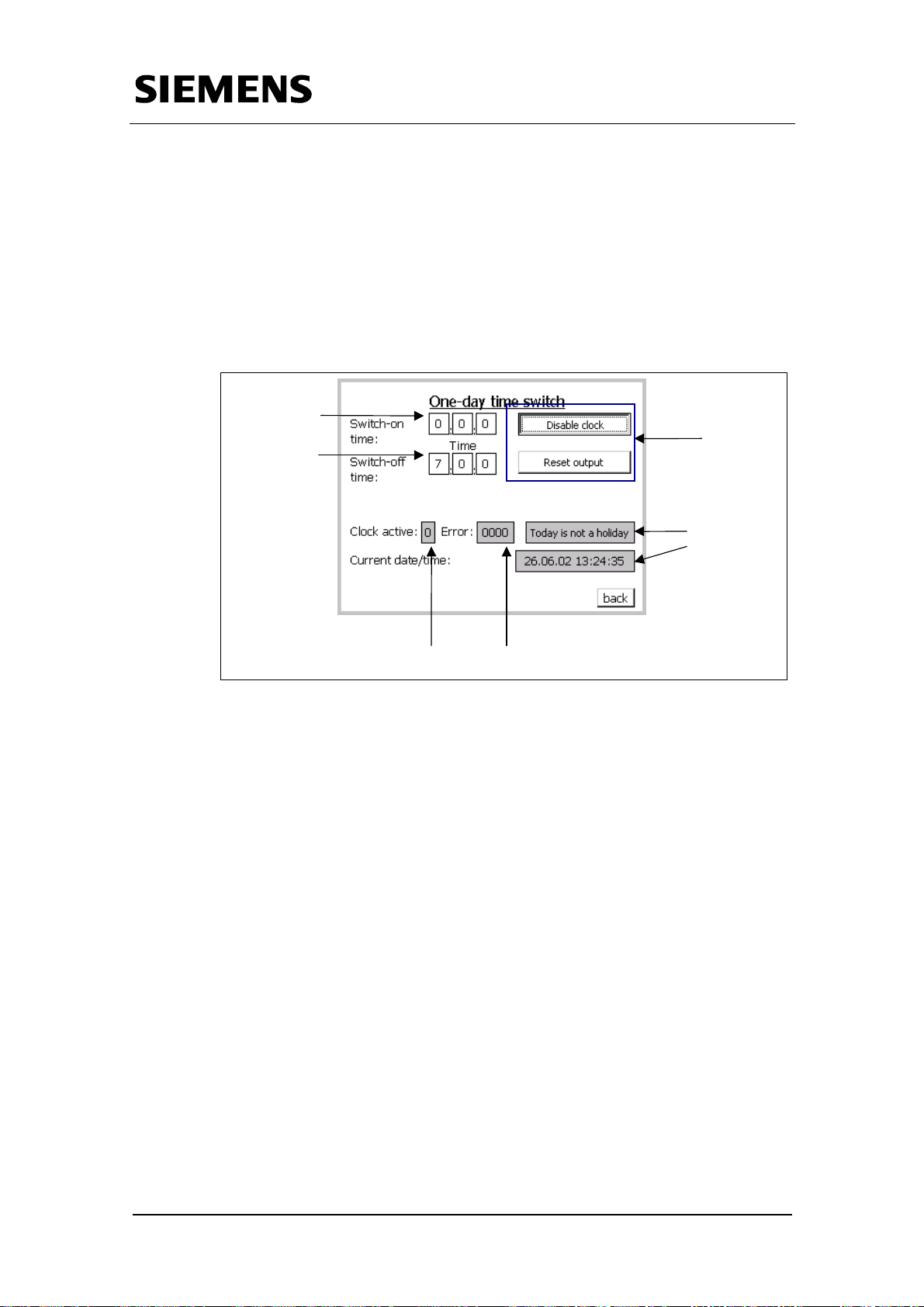
HMI with TP170A
The TP170A is a WindowsCE device of the lower performance range. A
graphical user interface of 12 cm x 8 cm can be used for controlling and
monitoring.
An example (one-day time switch) of the HMI interface at TP170A is
illustrated below.
Switch-on ti m e
Switch-off ti me
Controlarameter
Datails on
current
system time
Dokument-Eigenschaft. All rights reserved
BID21669756_Zeitschaltuhr_einfach_DOKU_v20_e.doc
Copyright © Siemens AG Fehler! Unbekannter Name für
Output
Error
Fig. 2-10 HMI interface for the one-month time switch at the OP3
Enable Clock:
The parameter is used for enabling or disabling the clock.
Reset Output:
The Reset parameter is used for resetting the output of the clock when
problems occur.
Rev. B - final 19.07.2002 20/84
Page 21
Warranty, Liability and Support
Time switch based on the S7-300/400 CPUs with simple HMI system
including radio-controlled clock connection
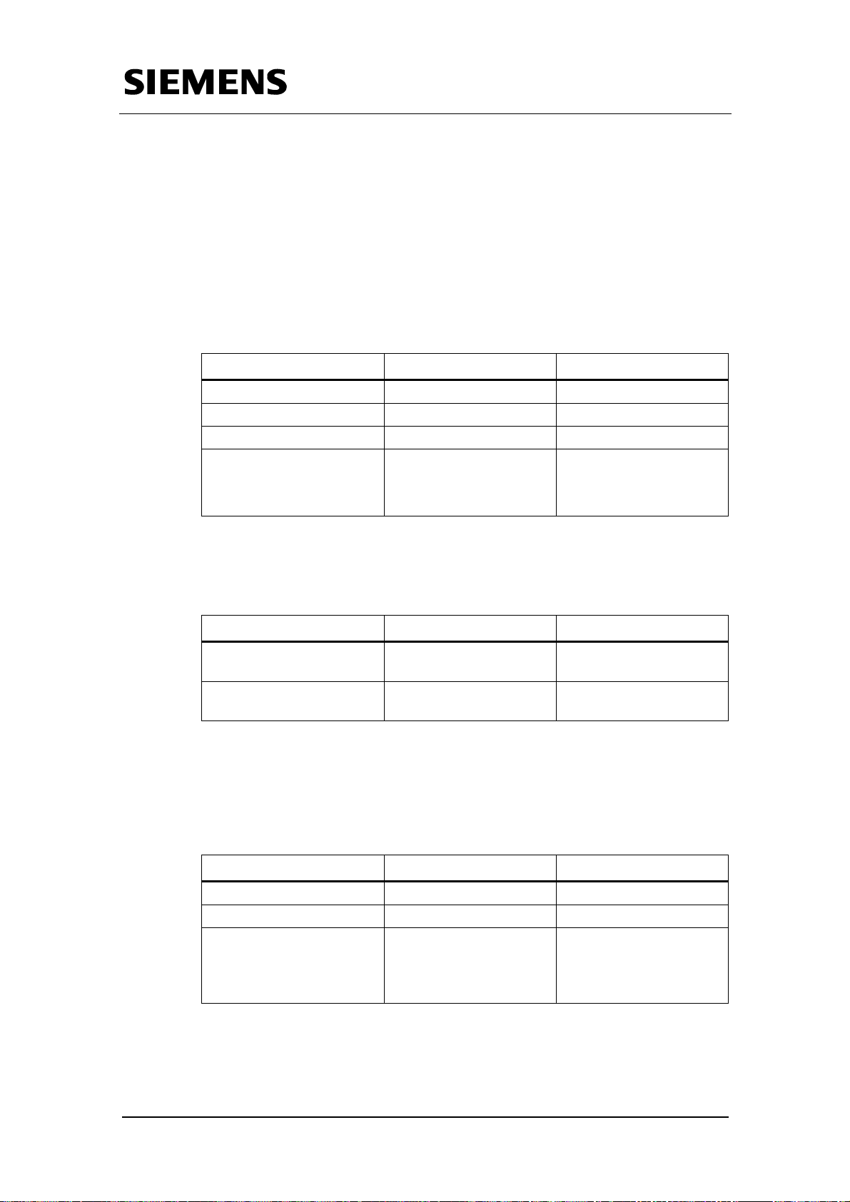
2.3 Standard components required
2.3.1 Hardware components
The following hardware components are required to use the application.
Table 2-1 Hardware components required
Component MLFB Description
PS 307 6ES7307-1BA00-0AA0 or similar power supply
CPU 315-2 DP 6ES7-315-2AG10-0AB0 or similar CPU
PG740 PIII or equal PC
OP3
or alternative
TP170A
6AV3 503-1DB10
6AV6 545-0BA15-2AX0
or similar HMI system
Dokument-Eigenschaft. All rights reserved
BID21669756_Zeitschaltuhr_einfach_DOKU_v20_e.doc
Copyright © Siemens AG Fehler! Unbekannter Name für
Optional hardware components (required only when radio-controlled clock
is to be used) :
Tabelle 2-2 Optional hardware components
Component MLFB Description
SM 321 6ES7 321-7BH00-0AB0
Radio receiver SIPLUS
DCF77
6AG1057-1AA03-0AA0
2.3.2 Software components
The following software components are required to implement our example.
Table 2-3 Software components required
Component MLFB Description
STEP7 V5.2 6ES7810-4CC06-0YX0
ProTool V6.0 6AV6582-2BX06-0XA0
Windows NT 4.0 SP 6a
or alternative
or similar digital input
module
or SICLOCK (see
appendix)
Windows 2000 SP 2
Rev. B - final 19.07.2002 21/84
Page 22
Warranty, Liability and Support
Time switch based on the S7-300/400 CPUs with simple HMI system
including radio-controlled clock connection
Optional software components (required only when a radio-controlled clock
is to be used):
Tabelle 2-4 Optional software component
Component Description
Dokument-Eigenschaft. All rights reserved
BID21669756_Zeitschaltuhr_einfach_DOKU_v20_e.doc
Copyright © Siemens AG Fehler! Unbekannter Name für
FB77 “DCF77_FB”
This standard function block has already been
implemented in this application. It is required only when a
radio-controlled clock is to be used.
Regardless of this application a STEP7 project including
the function block FB77 is available at the following
address:
http://www.ad.siemens.de/siplus/additions/html_00/doku
mentation.shtml
Rev. B - final 19.07.2002 22/84
Page 23
Copyright © Siemens AG 2005 All rights reserved
BID21669756_Zeitschaltuhr_einfach_DOKU_v20_e.doc
Time switch based on the S7-300/400 CPUs with simple HMI system including radio-controlled clock connection
2.4 Application software components required and their "product features"
This application was produced using the following application software components:
Table 2-2 STEP 7 application software
Serial No. Name Function description Technical data Ambient Conditions
1 Day (FB120)
2 Week (FB121)
3 Month (FB122)
4 Year (FB123)
The FB “DAY” checks, whether the current system time in the S7 CPU
is within the parameterized time range at the input parameters of the
block. If this is the case, the output is set to “1”. Otherwise the output is
“0”.
The FB “Week” checks, whether current system time and current day of
the week in the S7 CPU are within the parameterized time range at the
input parameters of the block. If this is the case, the output is set to “1”.
Otherwise the output is “0”.
The FB “Month” checks, whether current system time and current day in
the month in the S7 CPU are within the parameterized time range at the
input parameters of the block. If this is the case, the output is set to “1”.
Otherwise the output is “0”.
The FB “Year” checks, whether current system time and current date in
the S7 CPU are within the parameterized time range at the input
parameters of the block. If this is the case, the output is set to “1”.
Otherwise the output is “0”.
– Language STL
– Storage
requirements:
610 bytes
– Instance DB: DB120
52 bytes
– Language STL
– Storage
requirements:
4750 bytes
– Instance DB: DB121
48 bytes
– Language STL
– Storage
requirements:
1054 bytes
– Instance DB: DB122
56 bytes
– Language STL
– Storage
requirements:
956 bytes
– Instance DB: DB123
56 bytes
– S7-CPU
– OB1
– S7-CPU
– OB1
– S7-CPU
– OB1
– S7-CPU
– OB1
Rev. B - final 19.07.2002 23/84
Page 24
Copyright © Siemens AG 2005 All rights reserved
BID21669756_Zeitschaltuhr_einfach_DOKU_v20_e.doc
Time switch based on the S7-300/400 CPUs with simple HMI system including radio-controlled clock connection
Serial No. Name Function description Technical data Ambient Conditions
5 Relative (FB124)
The FB “Relative” sets the output to “1”, if at the input “Enable” a
positive edge is identified. The output stays on “1” until the
parameterized time has elapse.
Additionally it can be parameterized, whether the parameterized time
restarts at any positive edge, or whether only the first edge change is
reacted to.
6 Summer_winter (FB103)
The FB “Summer_winter” changes the current system time in the S7CPU by plus or minus 1 hour, depending on whether the time
changeover has occurred from winter to summer or from summer to
winter time
– Language STL
– Storage
requirements:
598 bytes
– Instance DB: DB124
58 bytes
– Language STL
– Storage
requirements:
382 bytes
– S7-CPU
– OB1
– S7-CPU
– OB1
– Instance DB: DB103
44 bytes
7 Holidays (FC100)
The FC “Holidays” checks whether a date stored in this checked DB
coincides with the current system date in the S7-CPU and sets its
output to “1” accordingly.
– Language STL
– Storage
requirements:
– S7-CPU
– OB1
310 bytes
Rev. B - final 19.07.2002 24/84
Page 25
Time switch based on the S7-300/400 CPUs with simple HMI system
including radio-controlled clock connection
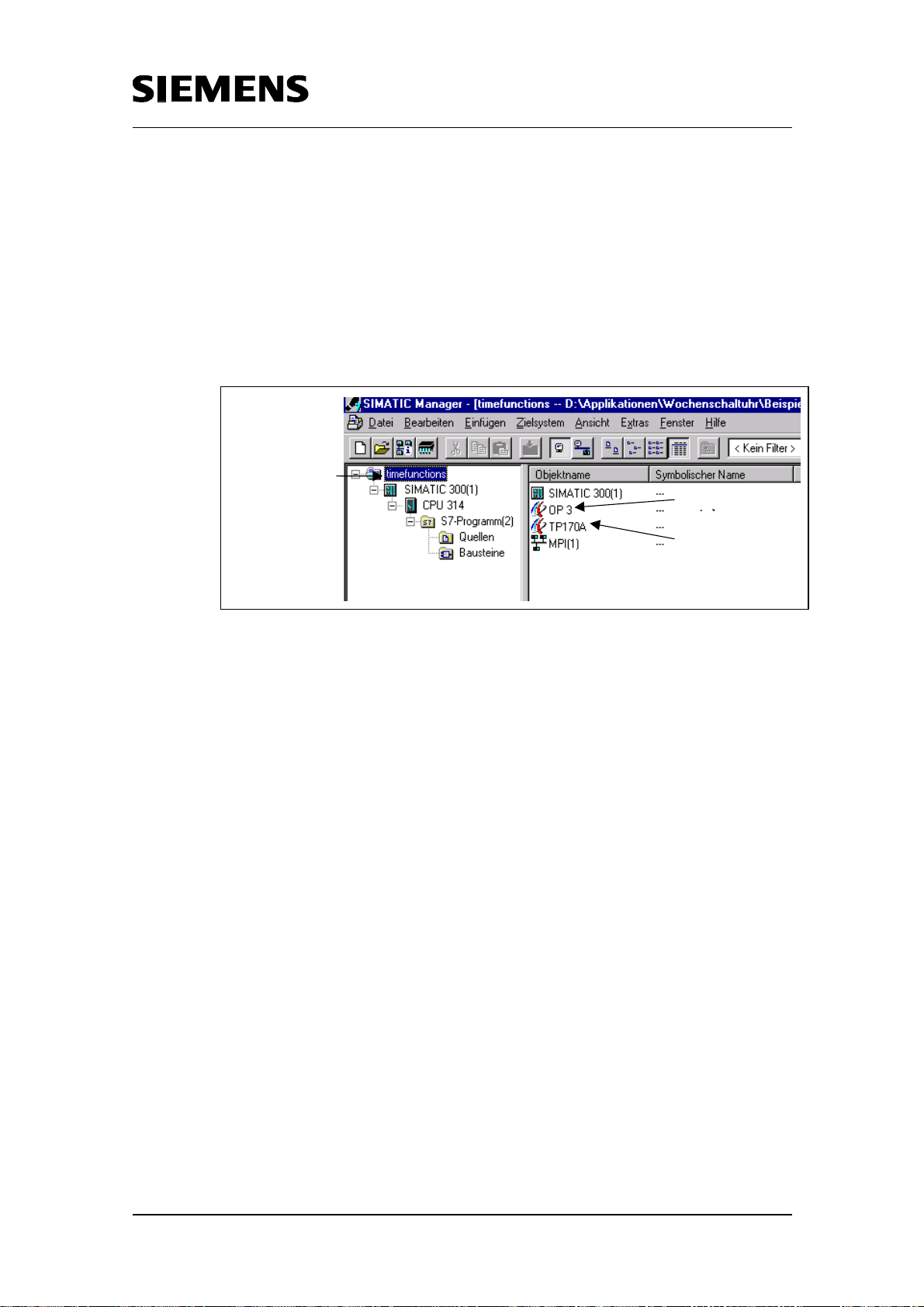
2.5 Installation with simple setup
The entire application software available for downloading has been
compressed in the “timefunc.exe” file. Copy the “timefunctions.exe“ file to a
separate folder and launch by double clicking on it. The project is
automatically extracted into the specified path including all respective subdirectories. Subsequently the extracted STEP7 project can be opened with
the SIMATIC Manager.
S7 project name
OP3-
Copyright © Siemens AG 2005 All rights reserved
BID21669756_Zeitschaltuhr_einfach_DOKU_v20_e.doc
TP170A project
Fig. 2-11 SIMATIC Manager
The project contains both ProTool projects for OP3 and TP170A. They can
be opened by double click in the SIMATIC Manager, providing ProTool has
been installed on the computer.
The hardware components for the S7 station may have to be adjusted in
the STEP7 project (if you are using different hardware components from
those given here) and is then be loaded into the S7 CPU.
Rev. B - final 19.07.2002 25/84
Page 26
Time switch based on the S7-300/400 CPUs with simple HMI system
including radio-controlled clock connection
3 Basic performance data
The basic data for the S7 blocks are available in the following table:
Table 3-1 Basic data for the function blocks
One-day
time
switch
No. Input
parameter
3 2 24h 1 1s 23:59:59
No. Output
parameter
Cycle
No. Time
intervals
Smallest
settable
interval
Largest
settable
interval
Copyright © Siemens AG 2005 All rights reserved
BID21669756_Zeitschaltuhr_einfach_DOKU_v20_e.doc
Seven-day
time
switch
3 2
7
days
1 1s
6 days,
23:59:59
One-
month
time
3 2
31
days
1 1s
30 days,
23:59:59
switch
One-year
time
3 2
switch
Relative
time
5 2 - 1 1s
switch
365
days
1 1s
364 days,
23:59:59
23 days,
23:59:59
The basic data for the radio receiver SIPLUS DCF77 are as follows:
Table 3-2 Basic data for the radio receiver
Radio frequency 77,5kHz
Protection class IP65
Dimensions
(W x H x D) 75 x 125*) x 75 mm
*) plus 25mm für screw connection
plus bending radius for cable
Voltage feed 24Vdc (20,4 ... 28,8Vdc)
Current consumption 50mA (typ.)
Rev. B - final 19.07.2002 26/84
Page 27

Time switch based on the S7-300/400 CPUs with simple HMI system
including radio-controlled clock connection
Part A2 : Function Mechanisms
Objectives of Part A2 :
Part A2 of this document provides the reader with information on the
following topics.
• Explanation of all function elements
• Description of the components which are easy to integrate in your own
applications
Copyright © Siemens AG 2005 All rights reserved
BID21669756_Zeitschaltuhr_einfach_DOKU_v20_e.doc
Rev. B - final 19.07.2002 27/84
Page 28

f
Time switch based on the S7-300/400 CPUs with simple HMI system
including radio-controlled clock connection
4 Examples of Function Mechanisms
4.1 Introduction
What will you find here?
Every hardware, standard and user software component is examined
separately and their functions described.
What can you do with it?
The example contains some (partial) solutions around the “time switching in
the S7” subject. With minor adjustments you can use them as the basis for
your own requirements.
4.2 Overview of the Structure Elements
Copyright © Siemens AG 2005 All rights reserved
BID21669756_Zeitschaltuhr_einfach_DOKU_v20_e.doc
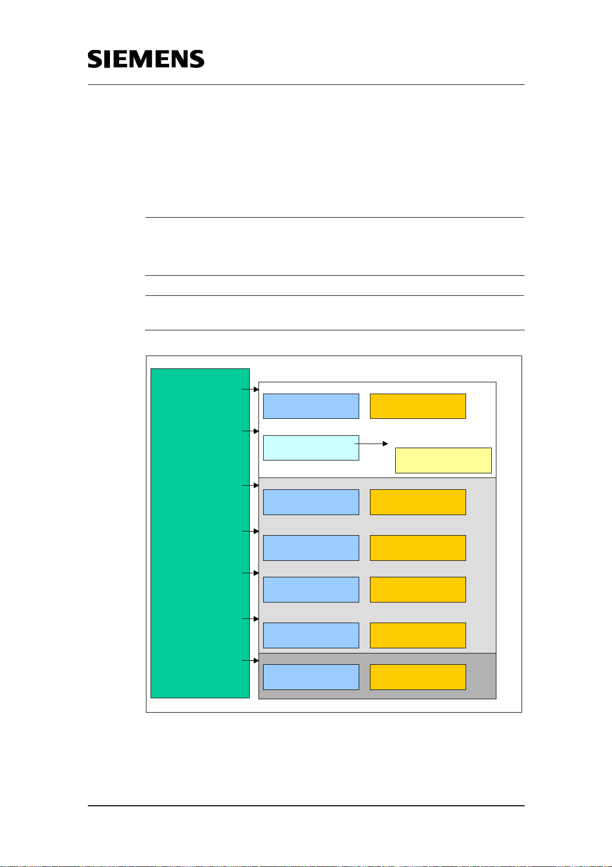
Figure 4-1 illustrates all function units of this application. They are
described one by one in the following chapters.
HMI Unit
S7-CPU
Program
OB1/TimeOB
Call of th e re s p . FB
with the respective
Instance DB, call o
further blocks for
program procedure
User interface
calls
connected via
further processed
Data interface
in Instance DB
“Time function“
Input parameter
Output parameter
Chapt. 4.4
displayed
Chapt. 4.3
feeds back
Process
Fig. 4-1 Structural layout of the application
Rev. B - final 19.07.2002 28/84
Page 29
_
_
Time switch based on the S7-300/400 CPUs with simple HMI system
including radio-controlled clock connection
4.3 STEP7 application level
Fig. 4-2 “STEP7 program overview“ gives you all the various elements of
the STEP7 program. The individual blocks are described in more detail in
the following sub-chapters.
Note
If certain blocks are not required, these can be removed from the displayed
program structure. This does not affect other blocks (“modular principle of
individual functions”).
Note
The function blocks have an exemplary, given numbering which can be changed.
Copyright © Siemens AG 2005 All rights reserved
BID21669756_Zeitschaltuhr_einfach_DOKU_v20_e.doc
OB1
OB1
(Chapter 4.3.3.1)
call summer
call summer
callcheck_holidaysFC100
callcheck_holidaysFC100
callday FB120
callday FB120
call weekFB121
call weekFB121
call monthF B122
call monthF B122
call yearFB123
call yearFB123
call relativ FB124
call relativ FB124
winterFB103 FB103
winterFB103 FB103
(Kapitel 4.3.3.1)
prüfe, ob Sommer-/Winterzeit-
check whether summer/winter
umschaltungstattge funden hat
time changeover occurred
(Chapter 4.3.3.2)
(Kapitel 4.3.3.2)
FC100
FC100
prüfe, ob aktuelles Datum ein
check whether current date is
Feiertag oder Sonderta g ist
holiday or special day
(Chapter 4.3.1.1)
(Kapitel 4.3.1.1)
FB120
FB120
prüfe, ob aktuelle Zeit impara-
check whether current time is
metrie r t e n Ze it raum liegt
within parameterized range
(Chapter 4.3.1.2)
(Kapitel 4.3.1.2)
FB121
FB121
prüfe, ob aktuelle Zeit impara-
check whether current time is
metrie r t e n Ze it raum liegt
within parameterized range
(Chapter 4.3.1.3)
(Kapitel 4.3.1.3)
FB122
FB122
prüfe, ob aktuelle Zeit impara-
check whether current time is
metrie r t e n Ze it raum liegt
within parameterized range
(Chapter 4.3.1.4)
(Kapitel 4.3.1.4)
FB123
FB123
prüfe, ob aktuelle Zeit impara-
check whether current time is
metrie r t e n Ze it raum liegt
within parameterized range
FB124
FB124
(Chapter 4.3.2)
(Kapitel 4.3.2)
prüfe, ob aktuelle Zeit impara-
check whether current time is
metrie r t e n Ze it raum liegt
within parameterized range
DB103
DB103
InstanzDB zu FB103
InstancDB to FB103
DB100
DB100
DB with holiday/special days
DB mit Feier- und Sonderta gen
DB120
DB120
InstanzDB zu FB120
Instance DBto FB120
DB121
DB121
InstanzDB zu FB121
InstancDB to FB121
DB122
DB122
InstanzDB zu FB122
InstancDB to FB122
DB123
DB123
InstanzDB zu FB123
InstancDB to FB123
DB124
DB124
InstanzDB zu FB124
InstancDB to FB124
Additional functions
Absolute
ime switching functions
Relative
ime switching function
Fig. 4-2 STEP7 program overview
Rev. B - final 19.07.2002 29/84
Page 30
Time switch based on the S7-300/400 CPUs with simple HMI system
including radio-controlled clock connection
4.3.1 Absolute time switching functions
The absolute time switching functions include
• One-day time switch
• Seven-day time switch
• One-month time switch
• One-year time switch
Each of the blocks has the following inputs:
• EnableClock of “BOOL“ type
Value = 1: Clock enabled
Value = 0: Clock not enabled
• Time_To_Check of “UDT“ type
The parameter contains the time range in which the clock is to be active,
with absolute switch-on and switch-off time. The parameter is specific for
each time switch
Copyright © Siemens AG 2005 All rights reserved
BID21669756_Zeitschaltuhr_einfach_DOKU_v20_e.doc
Important
!
For the one-week time switch, the parameter “Time_To_Check“ is an in/out
parameter!
• Reset of “BOOL“ type
Value = 1: Clock is reset
Value = 0: Clock runs in “Normal operation”
Each of the blocks has the following outputs:
• Q = clock active of “BOOL“ type
The parameter indicates whether the clock is active.
Value = 1: Clock is active
Value = 0: Clock not active
• Error of “INT“ type
Value = 0: No error has occurred
Value <> 0: An error has occurred
possible errors:
Return value of called SFCs in the block (e.g. SFC1 “Read_Clk“)
8000h at limit value violation at the input parameters
8001h if switch-on time equal switch-off time
Rev. B - final 19.07.2002 30/84
Page 31
Time switch based on the S7-300/400 CPUs with simple HMI system
including radio-controlled clock connection
Note
The input parameter ”EN” and the output parameter “ENO” are default parameters
at the S7 blocks. Closer information is available in the documentation and the
STEP7 online help.
Note
The time switching functions are discussed in detail below. The only different
parameter here is “Time_To_Check“ of the “UDT“ type, whose parameterization is
always given. All other parameters have the same structure for all different time
switching functions.
The Start and Reset parameters are subsequently referred to as control
parameters.
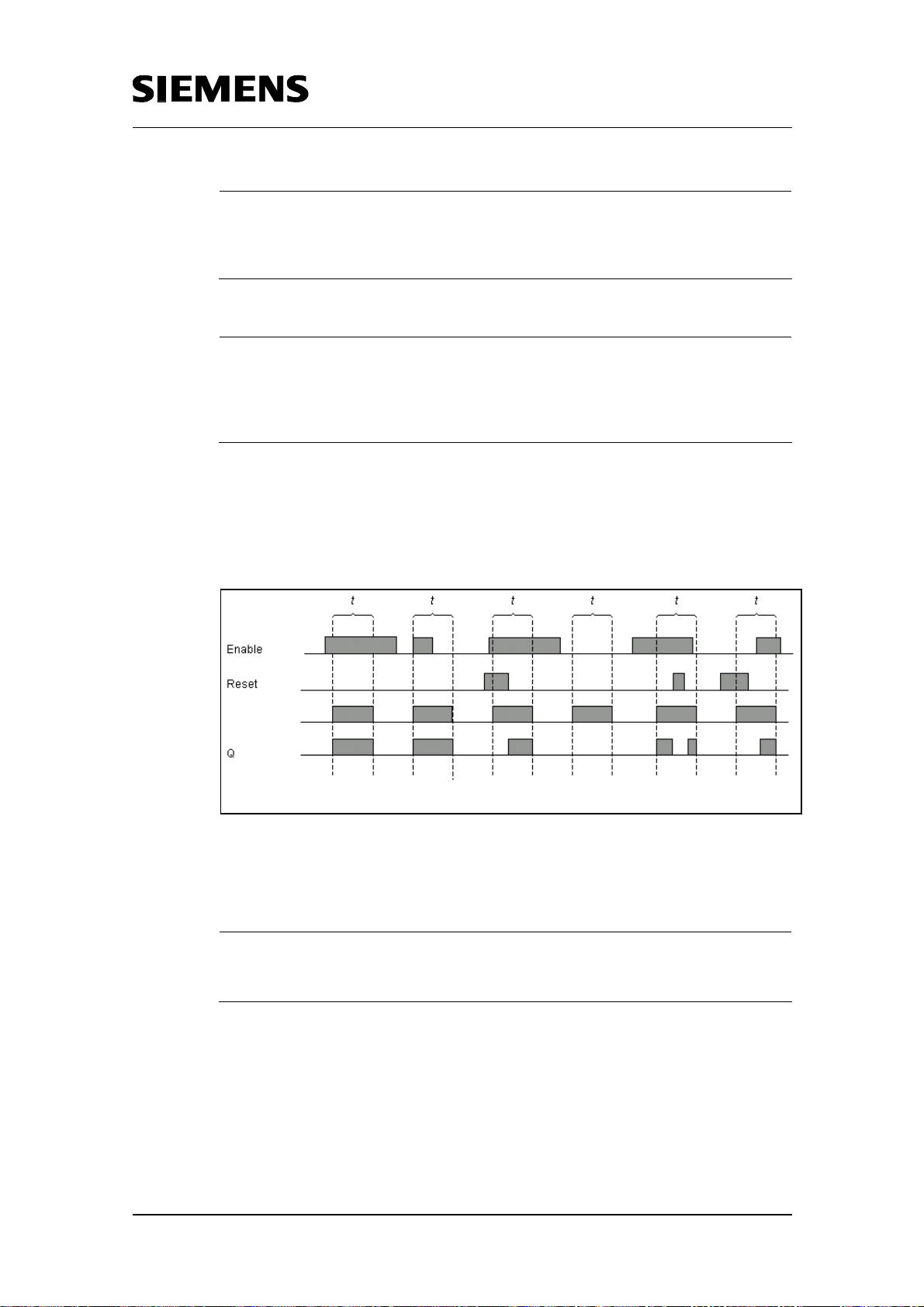
The following pulse diagram illustrates how the behavior of the input signals
“ReleaseClock“, “Time_To_Check“ and “Reset“, and the output “Clock
active“ relate to each other:
Copyright © Siemens AG 2005 All rights reserved
ime range
BID21669756_Zeitschaltuhr_einfach_DOKU_v20_e.doc
t is a programmed time range (time switch active)
Fig. 4-3 Pulse diagram
Note
The pulse diagram (Fig. 4-3) applies for all absolute function blocks, which are
described in detail below.
4.3.2 One-day time switch
The block for the one-day time switch “day” FB120 is parameterized as
illustrated in the figure below. Data block DB120 is used as instance data
block:
Rev. B - final 19.07.2002 31/84
Page 32

Time switch based on the S7-300/400 CPUs with simple HMI system
including radio-controlled clock connection
Fig 4-4 Configuration “one-day time switch”
Basic data/parameterizability:
Copyright © Siemens AG 2005 All rights reserved
BID21669756_Zeitschaltuhr_einfach_DOKU_v20_e.doc
RAM requirements:
day: 760 bytes
Instance DB: 52 bytes
The parameter “Time_To_Check“ is a structure of the “day_udt“ (UDT1)
type. It contains:
• Start hour, start minute, start second summarized as “starttime” with
structure of the “times” (UDT6) type
• End hour, end minute, end second summarized as “endtime” with
structure of the “times” (UDT6) type
4.3.3 Seven-day time switch
The block for the seven-day time switch “week” FB121 is parameterized as
illustrated in the figure below. Data block DB121 is used as instance data
block:
Fig 4-5 Configuration “seven-day time switch”
Rev. B - final 19.07.2002 32/84
Page 33

Time switch based on the S7-300/400 CPUs with simple HMI system
including radio-controlled clock connection
Basic data/parameterizability:
RAM requirements:
week: 4750 bytes
Instance DB: 48 bytes
The parameter “Time_To_Check“ is a structure of the “week_udt“ (UDT2)
type. It contains:
• Start day
1 to 7: Sunday to Saturday
8: Monday to Friday
9: Saturday to Sunday
• Start hour, start minute, start second summarized as “starttime” with
structure of the “times” (UDT6) type
Copyright © Siemens AG 2005 All rights reserved
BID21669756_Zeitschaltuhr_einfach_DOKU_v20_e.doc
• End day
1 to 7: Sunday to Saturday
8: Monday to Friday
9: Saturday to Sunday
• End hour, end minute, end second summarized as “endtime” with
structure of the “times” (UDT6) type
If the parameter “Start day” has a value between 1 and 7, only a value
between 1 and 7 must be input at the end day as well. If the parameter
“Start day” equals 8 or 9, only 8 or 9 must be input at the end day as well.
4.3.4 One-month time switch
The block for the one-month time switch “month” FB122 is parameterized
as illustrated in the figure below. Data block DB122 is used as instance
data block:
Fig 4-6 Configuration “one-month time switch”
Rev. B - final 19.07.2002 33/84
Page 34

Time switch based on the S7-300/400 CPUs with simple HMI system
including radio-controlled clock connection
Basic data/parameterizability:
RAM requirements:
month: 1204 bytes
Instance DB: 56 bytes
The parameter “Time_To_Check“ is a structure of the “month_udt“ (UDT3)
type. It contains:
• Start day
1 to 31: corresponds to day in month
32: Last day in month
• Start hour, start minute, start second summarized as “starttime” with
structure of the “times” (UDT6) type
• End day
1 to 31: corresponds to day in month
32: Last day in month
Copyright © Siemens AG 2005 All rights reserved
BID21669756_Zeitschaltuhr_einfach_DOKU_v20_e.doc
Note
When parameterizing start day and end day, it must be taken into account that not
every month has 31 days. If a function is to be executed at or until or from the last
day of the month, a 32 must be entered instead of 28, 30 or 31. The block checks
the current month and automatically sets the end day to the last day of that month.
• End hour, end minute, end second summarized as “endtime” with
structure of the “times” (UDT6) type
4.3.5 One-year time switch
The block for the one-year time switch “year” FB123 is parameterized as
illustrated in the figure below. Data block DB123 is used as instance data
block:
Fig 4-7 Configuration “one-year time switch”
Rev. B - final 19.07.2002 34/84
Page 35

Time switch based on the S7-300/400 CPUs with simple HMI system
including radio-controlled clock connection
Basic data/parameterizability:
RAM requirements:
year: 1110 bytes
Instance DB: 56 bytes
The parameter “Time_To_Check“ is a structure of the “year_udt“ (UDT4)
type. It contains:
• Start month
• Start day
• Start hour, start minute, start second summarized as “starttime” with
structure of the “times” (UDT6) type
• End month
• End day
Copyright © Siemens AG 2005 All rights reserved
BID21669756_Zeitschaltuhr_einfach_DOKU_v20_e.doc
• End hour, end minute, end second summarized as “endtime” with
structure of the “times” (UDT6) type
4.3.6 Relative time switch
The module for relative time switching has the following input parameters:
• EnableClock of “BOOL“ type
Value = 1: Clock enabled
Value = 0: Clock not enabled
• Reset of “BOOL“ type
Value = 1: Each positive edge is evaluated at the parameter “StartTime“
-> the time is restarted every time
Value = 0: The first positive edge at the parameter “StartTime” is
evaluated. If the time has elapsed, the clock can be restarted by another
edge change at the input “StartTime”.
• The parameter “Time_To_Go“ is a structure of the “relative_udt“ (UDT5)
type. It contains:
- Number of days
- Number of hours
- Number of minutes
- Number of seconds
• Reset of “BOOL“ type
Value = 1: Clock is reset
Value = 0: Clock runs in “Normal operation”
The module for relative time switching has the following in/out parameters:
• StartTime of “BOOL“ type
At a positive edge change at this parameter, the clock is active and
stays active until the time at the parameter “time_to_go“ has elapsed.
Rev. B - final 19.07.2002 35/84
Page 36

Time switch based on the S7-300/400 CPUs with simple HMI system
including radio-controlled clock connection
The control parameters for the relative time switch are EnableClock,
CheckEdge, Reset and StartTime.
The control parameters and the output relate to each other as illustrated in
the following pulse diagrams:
CheckEdge = 0:
EnableCloc
CheckEdg
StartTim e
Reset
Copyright © Siemens AG 2005 All rights reserved
BID21669756_Zeitschaltuhr_einfach_DOKU_v20_e.doc
Time active
Output
Fig. 4-8 Pulse diagram CheckEdge = 0
Rev. B - final 19.07.2002 36/84
Page 37

Time switch based on the S7-300/400 CPUs with simple HMI system
including radio-controlled clock connection
CheckEdge = 1:
EnableCloc
CheckEdg
StartTim
Reset
Time active
Output
Fig. 4-9 Pulse diagram CheckEdge = 1
Copyright © Siemens AG 2005 All rights reserved
BID21669756_Zeitschaltuhr_einfach_DOKU_v20_e.doc
The block for the relative time switch “relative ” FB124 is parameterized as
illustrated in the figure below. Data block DB124 is used as instance data
block:
Fig. 4-10 Configuration “relative time switch”
Basic data
RAM requirements:
relative: 602 bytes
Instance DB: 58 bytes
Rev. B - final 19.07.2002 37/84
Page 38

Time switch based on the S7-300/400 CPUs with simple HMI system
including radio-controlled clock connection
4.3.7 Additional functions
In addition to the blocks for the absolute time switch and the relative time
switch, blocks for summer/winter time changeover as well as for holiday
recognition are also supplied.
Summer/wintertime changeover
Copyright © Siemens AG 2005 All rights reserved
BID21669756_Zeitschaltuhr_einfach_DOKU_v20_e.doc
Standard: Program controlled (FB 103 “summer_winter”)
The block for the summer/winter time changeover adds exactly 1 hour to
the current system time in the S7-CPU, when changing from winter to
summer time, and subtracts exactly 1 hour when changing from summer to
winter time. Changeover from winter to summer time occurs at the last
Saturday in March, from summer to winter time at the last Saturday in
October.
The block has the following input parameter:
• active of “BOOL“ type
If the parameter = 1, the block is executed. If the parameter = 0,
executing the block is prevented.
The block has the following output parameters:
• summertime of “BOOL“ type
Value = 1: It is summer time
Value = 0: It is winter time
• Error of “INT“ type
Not equal 0, if during processing an error has occurred.
The block for the summer/winter time changeover “summer_winter” FB103
is parameterized as illustrated in the figure below. Data block DB103 is
used as instance data block:
Fig 4-11 Configuration “summer/winter time changeover”
Basic data
RAM requirements:
summer_winter: 382 bytes
Instance DB: 48 bytes
Rev. B - final 19.07.2002 38/84
Page 39

Time switch based on the S7-300/400 CPUs with simple HMI system
including radio-controlled clock connection
Option: Radio-clock controlled (FB 77 “DCF77_FB”)
Optionally the possibility is offered to use a radio-controlled clock for
summer/winter time changeover instead of the block described above. In
case the radio-controlled option has been selected in the ProTool view, the
block FB103 „summer_winter“ is deactivated, instead of that the block
FB77 „DCF77_FB“ is being called, which evaluates the signals received by
the radio clock.
The block has the following input parameters:
• SekTakt of „BOOL“ type
Input „second clock pulse“ from DCF77 module
• Data of „BOOL“ type
Input bit pattern, data from DCF77 module
• SekCPU of „BOOL“ type
CPU clock memory bit with frequency 1 Hz
Copyright © Siemens AG 2005 All rights reserved
BID21669756_Zeitschaltuhr_einfach_DOKU_v20_e.doc
• DCF77 of „TIMER“ type
Timing element for minute recognition
The block has the following output parameters:
• Zeitzone of „BOOL“ type
Value = 1: It is summer time
Value = 0: It is winter time
• Umsch_Zeitzone of „BOOL“ type
Value = 1: changeover from summer to winter time or the other way
round will occur in one hour
• Min_Puls of „BOOL“ type
with the negative edge a new minute begins and/or the clock is being set
• Fehler of „BOOL“ type
Value = 1: for three minutes or longer no valid telegram has been
received
The block for the connection of the radio-controlled clock FB77
„DCF77_FB“ is parameterized as illustrated in the figure below. Data block
DB77 is used as instance data block:
Rev. B - final 19.07.2002 39/84
Page 40

Time switch based on the S7-300/400 CPUs with simple HMI system
including radio-controlled clock connection
Fig. 4-12 Configuration „DCF77_FB“
Basic data:
RAM requirements:
DCF77_FB: 2960 bytes
Copyright © Siemens AG 2005 All rights reserved
BID21669756_Zeitschaltuhr_einfach_DOKU_v20_e.doc
Instance DB: 58 bytes
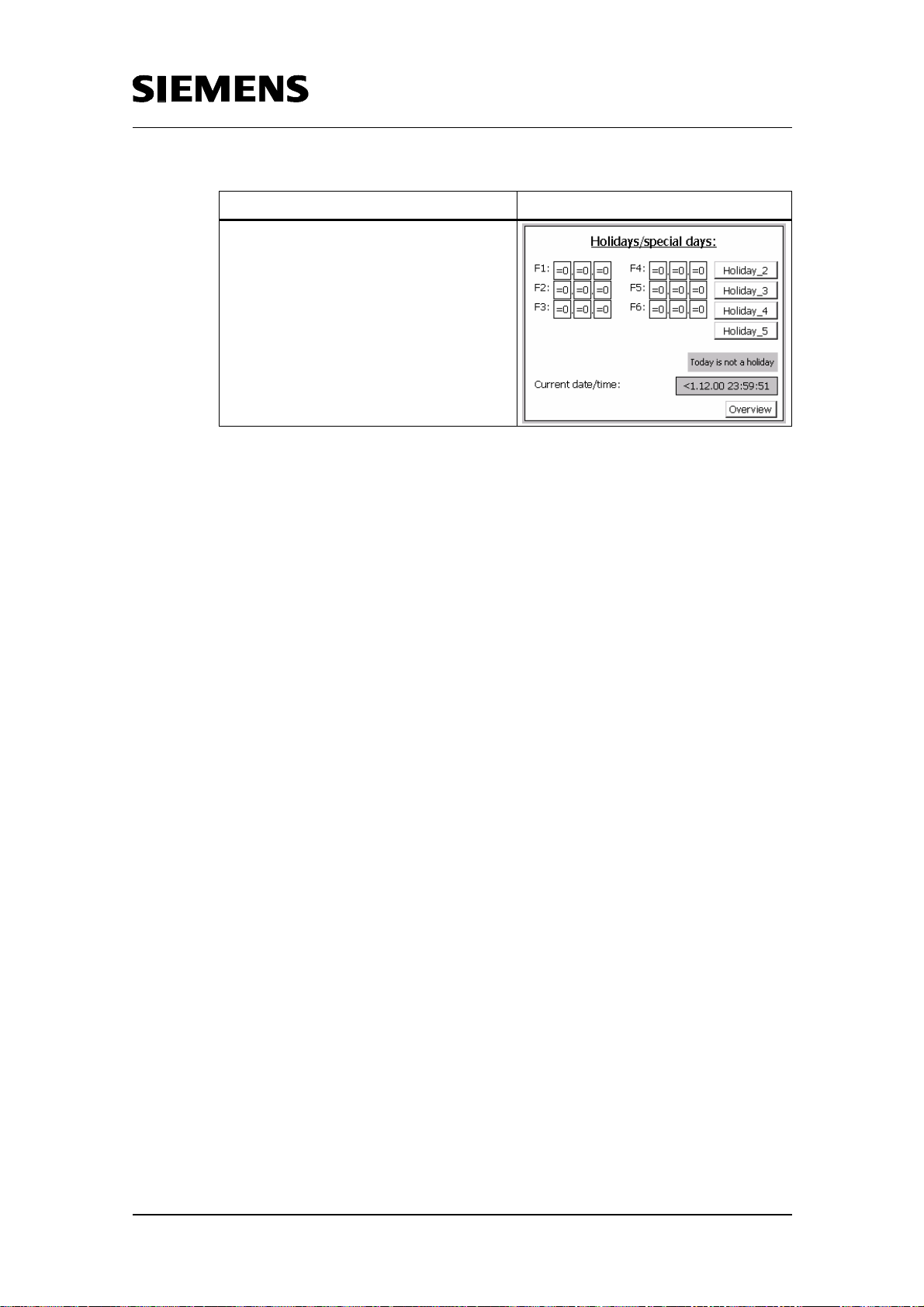
Holiday recognition
The block checks a DB with 30 memory slots for holidays or special days,
and sets the output to “1”, if the current day of the system time of the S7CPU coincides with a data in this DB.
The block has the following input parameter:
• DB_Nr of “INT“ tpye:
contains the number of the DB in which holidays and special days are
stored
Fig. 4-13 Layout of the DB to be checked
The block has the following output parameters:
Rev. B - final 19.07.2002 40/84
Page 41

Time switch based on the S7-300/400 CPUs with simple HMI system
including radio-controlled clock connection
• holiday of “BOOL“ type
Value = 1: current day is a holiday or special day
Value = 0: current day is no holiday or special day
The block for recognizing holidays and special days “holidays” FC100 is
parameterized as illustrated below:
Fig. 4-14 Configuration “recognizing holidays and special days“
4.4 HMI System
The HMI system used in this example is an OP3 or alternatively a TP170A.
Copyright © Siemens AG 2005 All rights reserved
BID21669756_Zeitschaltuhr_einfach_DOKU_v20_e.doc
Note
Only two of the user interfaces are described here as an example. A detailed
description is available in Chapter 6.
4.4.1 Operation at the OP3
The SIMATIC HMI device OP3 is a text-based display of the lower
performance range.
7 views of time switching functions are available on the OP3:
• One-day time switch
• Seven-day time switch
• One-month time switch
• One-year time switch
• Relative time switch
• Summer/wintertime changeover
• Holidays
Rev. B - final 19.07.2002 41/84
Page 42

Time switch based on the S7-300/400 CPUs with simple HMI system
including radio-controlled clock connection
Table 4-1 OP3 views
Clock/function Illustration
One-month time switch
Copyright © Siemens AG 2005 All rights reserved
Relative time switch
BID21669756_Zeitschaltuhr_einfach_DOKU_v20_e.doc
Each view consists of several lines, two of which are always visible at the
OP3. Input boxes are available for entering the absolute switch-on and
switch-off times. Next to these input boxes, the clock status, possible errors
during block processing, and current S7-CPU system time are given in
output boxes.
Rev. B - final 19.07.2002 42/84
Page 43

Time switch based on the S7-300/400 CPUs with simple HMI system
including radio-controlled clock connection
4.4.2 Operation at the TP170A
The TP170A is a low-end device. It is based on the standard operating
system WindowsCE.
The TP170A has 9 views:
Table 4-2 TP170A views
Clock/function Illustration
Overview
Copyright © Siemens AG 2005 All rights reserved
One-day time switch
BID21669756_Zeitschaltuhr_einfach_DOKU_v20_e.doc
Seven-day time switch
Rev. B - final 19.07.2002 43/84
Page 44

Time switch based on the S7-300/400 CPUs with simple HMI system
including radio-controlled clock connection
Clock/function Illustration
One-month time switch
One-year time switch
Copyright © Siemens AG 2005 All rights reserved
BID21669756_Zeitschaltuhr_einfach_DOKU_v20_e.doc
Relative time switch
Summer/wintertime changeover (in the
figure the setting „Program-controlled
changeover“ is active)
Rev. B - final 19.07.2002 44/84
Page 45
Time switch based on the S7-300/400 CPUs with simple HMI system
including radio-controlled clock connection
Clock/function Illustration
5 holiday views (only one view is given
here as an example)
Each view is a graphical user interface which provides input and output
boxes. Input boxes are available for entering the absolute switch-on and
switch-off times. Next to these input boxes, the clock status, possible errors
during block processing, and current S7-CPU system time are given in
output boxes.
Copyright © Siemens AG 2005 All rights reserved
BID21669756_Zeitschaltuhr_einfach_DOKU_v20_e.doc
Rev. B - final 19.07.2002 45/84
Page 46

Time switch based on the S7-300/400 CPUs with simple HMI system
including radio-controlled clock connection
Part B: Installation of the Sample Application
Objectives of Part B:
Part B of this document provides the reader with information on the
following topics.
• How to install the sample application with all the hardware and software
components
• How to manipulate the application
Copyright © Siemens AG 2005 All rights reserved
BID21669756_Zeitschaltuhr_einfach_DOKU_v20_e.doc
Rev. B - final 19.07.2002 46/84
Page 47
Time switch based on the S7-300/400 CPUs with simple HMI system
including radio-controlled clock connection
5 Installation of Hardware and Software
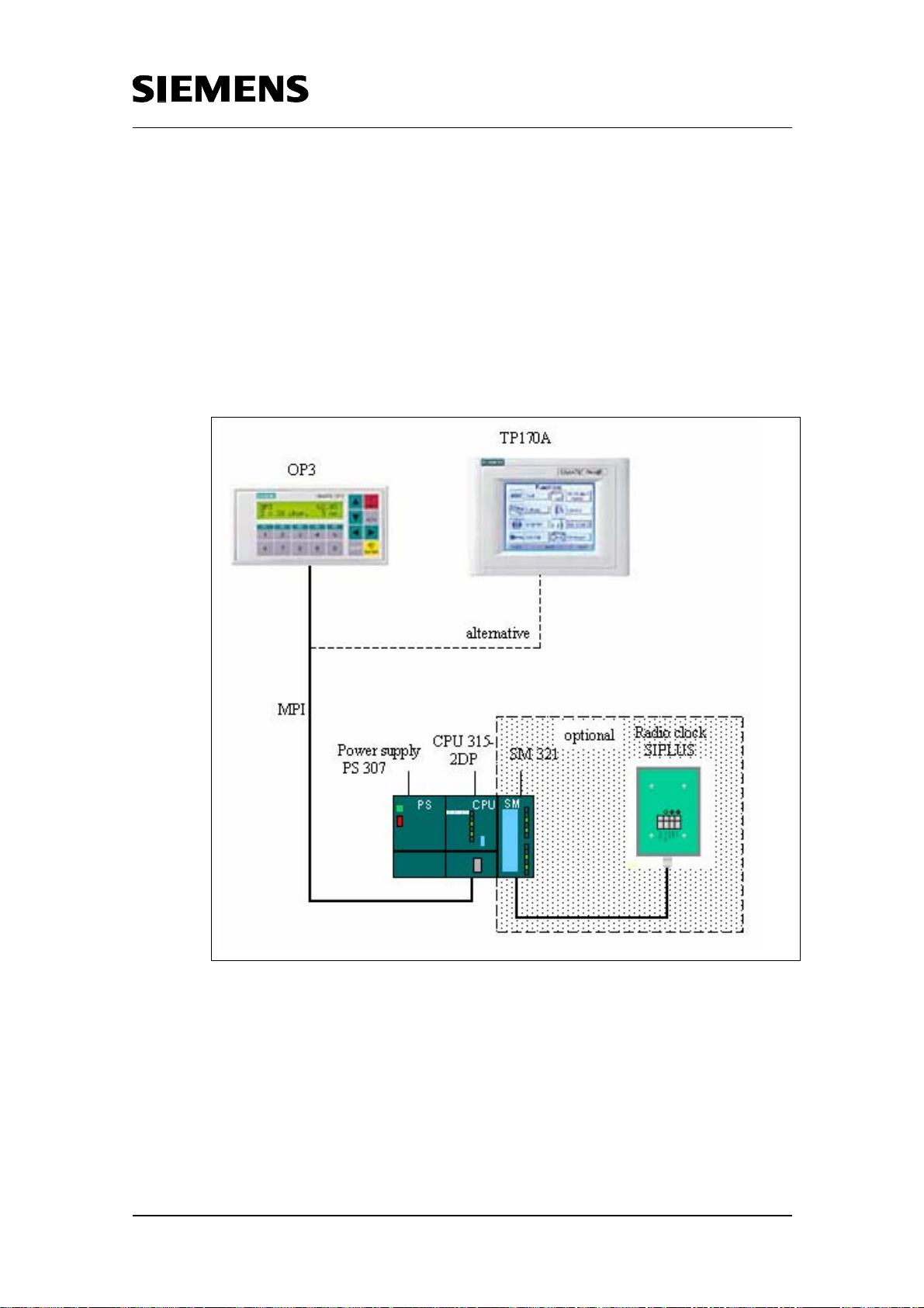
5.1 Hardware configuration
S7 Hardware configuration
For the hardware components required, please refer to chapter 2.3.1. “HW
components“.
Copyright © Siemens AG 2005 All rights reserved
BID21669756_Zeitschaltuhr_einfach_DOKU_v20_e.doc
Fig. 5-1 Hardware configuration
Set up the components as directed in the manuals for the modules and
connect the panel to the S7-CPU via an MPI cable.
Rev. B - final 19.07.2002 47/84
Page 48

Time switch based on the S7-300/400 CPUs with simple HMI system
including radio-controlled clock connection
Optional: hardware configuration with radio clock
The SIPLUS DCF77 radio clock module is connected to the voltage supply
unit / the SM 321 by means of a shielded 4-wire cable as follows:
PS SM 321 SIPLUS DCF77
E 0.0 Sec
E 0.1 DCF Data
L+ 24Vdc
M Ground
You may, of course, connect the radio clock also via other digital
inputs than those described here. In this case you only have to adjust
the parameter settings for "SekTakt" and "Data" in OB1
correspondingly when calling FB77 "DCF77_FB".
Copyright © Siemens AG 2005 All rights reserved
BID21669756_Zeitschaltuhr_einfach_DOKU_v20_e.doc
Functions of the LEDs on the radio clock module type SIPLUS
DCF77:
Important!
green LED '24Vdc': voltage supply is active
inner red LED 'DCF data': data transfer to the automation system
outer red LED 'sec': pulses received from the atomic clock at 1-second
intervals
The SIPLUS DCF77 should be positioned so that the radio clock signal is not
shielded by building facades of metal or similar obstacles. The module itself must
be protected against interference frequency and should not be placed dire ctly on a
metal surface.
Test proper signal reception at the place of installation by connecting the SIPLUS
DCF77 module to supply voltage. Proper reception of the radio signals is indicated
by the outer red LED which should be flashing at 1-second intervals. If the LED
does not react or if it flashes inconsistently, another installation location should be
found. Depending on the conditions of signal reception, clock setting normally
takes about 3 to 4 minutes; if an unfavorable location has been selected, it will take
some more time.
Rev. B - final 19.07.2002 48/84
Page 49

>
Time switch based on the S7-300/400 CPUs with simple HMI system
including radio-controlled clock connection
5.2 Software installation
Requirements: STEP7 V5.1 has already been installed with the NCM
package for Industrial Ethernet. In addition to STEP 7, ProTool V6 has
already been installed on your computer.
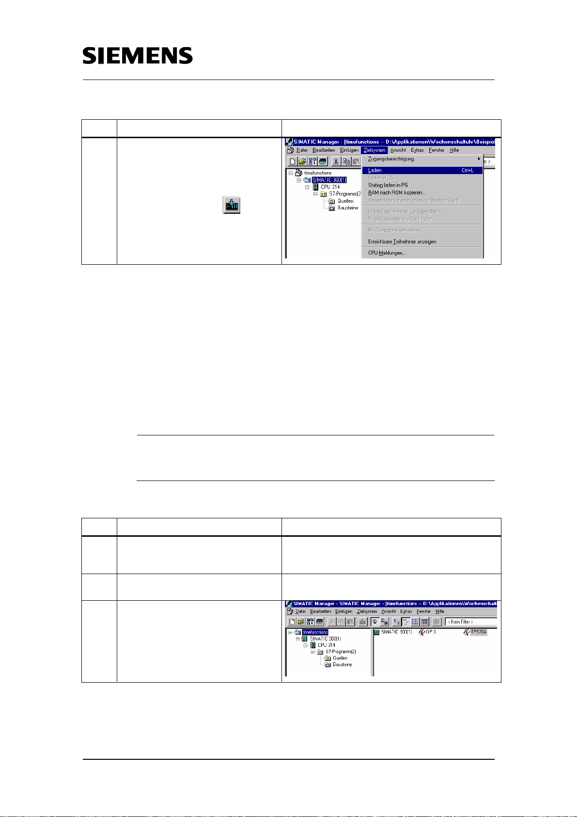
5.2.1 Loading the application software into the S7-CPU
The simplest way of loading the application software into the S7-CPU is via
the MPI. Connect the MPI interface of your PC with the MPI interface of the
S7-CPU. To complete the transfer you must perform the following steps:
Table 5-1 Loading the application software into the S7-CPU
Step Action Screenshot
Copyright © Siemens AG 2005 All rights reserved
BID21669756_Zeitschaltuhr_einfach_DOKU_v20_e.doc
1.
Open dialog box "Set PG/PC
Interface" with commands "Start
>Settings-> Control PanelPG/PC-Schnittstelle
einstellen [Set PG/PC
Interface]".
2.
Choose S7ONLINE as the “Access
Point of the Application“.
If this choice is not available to you,
create it by clicking
<Hinzufügen/Löschen
[Add/Remove]> (included in
options box under Access to
Application.
Rev. B - final 19.07.2002 49/84
Page 50

Time switch based on the S7-300/400 CPUs with simple HMI system
including radio-controlled clock connection
Step Action Screenshot
3.
In the options box "Zugangspunkt
der Applikation" [Interface
Parameter Assignment Used] select
“CP5611(MPI)“. Click
“Eigenschaften”
[Properties...].
4.
Enter the MPI address for the PC, in
this example the address “4“. Enter
the other bus parameters and close
the dialog with “OK“.
Copyright © Siemens AG 2005 All rights reserved
BID21669756_Zeitschaltuhr_einfach_DOKU_v20_e.doc
5.
Quit the dialog “PG/PC-
Schnittstelle einstellen“
[Set PG/PC Interface] by
pressing “OK“.
Rev. B - final 19.07.2002 50/84
Page 51
Time switch based on the S7-300/400 CPUs with simple HMI system
including radio-controlled clock connection
Step Action Screenshot
6.
Open the delivered project in the
SIMATIC Manager and select the
SIMATIC station. Load the project
into the S7-CPU via the menu
“Zielsystem > Laden“ [PLC >
Download] or with the
button.
5.2.2 Load the application software into the panel
The ProTool project must be loaded into the respective HMI device. There
are 2 options:
• MPI transfer
• Serial transfer
In this example the MPI transfer is described. Connect the MPI interface of
your PC with the MPI interface of the panel, here the TP170A.
Copyright © Siemens AG 2005 All rights reserved
BID21669756_Zeitschaltuhr_einfach_DOKU_v20_e.doc
Note
The same procedure is also necessary when using an OP3. In this case you must
open the OP3 project (see step 3) instead of the TP170A project.
Table 5-2 Loading the application software into the panel
Step Action Screenshot
1.
2.
3.
For setting the PG/PC interface
perform steps 1 to 5 of chapter 5.2.1
Open the delivered project in the
SIMATIC Manager.
Select the project name, double click
on “TP170A“. The project is opened
in ProTool.
Rev. B - final 19.07.2002 51/84
Page 52

Time switch based on the S7-300/400 CPUs with simple HMI system
including radio-controlled clock connection
Step Action Screenshot
4.
Make the necessary settings for the
transfer operation. Open the menu
“Datei > Transfer >
Einstellung...“ [File >
Transfer > Settings...].
5.
Select “MPI/PROFIBUS DP“ and
enter the OP address, “1“ in this
example.
Note:
The OP address must be identical
with the network parameterization in
ProTool. The settings are made
under “Controls”.
Copyright © Siemens AG 2005 All rights reserved
BID21669756_Zeitschaltuhr_einfach_DOKU_v20_e.doc
6.
Start the project transfer via the
menu “File -> Transfer ->
Start project transfer“.
Rev. B - final 19.07.2002 52/84
Page 53

Time switch based on the S7-300/400 CPUs with simple HMI system
including radio-controlled clock connection
Step Action Screenshot
7.
Answer the query whether you want
to save the configuration with “Ja“
[Yes].
8.
Subsequently generation is started,
and if successful, the project transfer
is started.
9.
Project transfer completed
successfully if no error message
occurred. Otherwise please check
your settings and try again.
Copyright © Siemens AG 2005 All rights reserved
BID21669756_Zeitschaltuhr_einfach_DOKU_v20_e.doc
Rev. B - final 19.07.2002 53/84
Page 54

Time switch based on the S7-300/400 CPUs with simple HMI system
including radio-controlled clock connection
6 Using the Application
For operating the application, respectively one example of a TO170A and a
OP3 are delivered in this application. How to use the application is
explained for two cases.
On application case uses many different absolute time switches plus
summer/winter time changeover, and is displayed at the HMI interface of
the TP170A (Chapter 6.1).
The second case includes several relative time switches as a pulse chain
and only two absolute time switches. This application case is explained
using the example of the OP3 (Chapter 6.2).
Note
How to use several time switches is described in Chapter 9.
Both application cases are included in the download on top of the “base
project”, and can be used as a basis for your own configuration.
Copyright © Siemens AG 2005 All rights reserved
BID21669756_Zeitschaltuhr_einfach_DOKU_v20_e.doc
6.1 Application case 1: Many time switches
In this case, several time switches of the absolute time switches are used
(one-day, seven-day, one-month, one-year time switch):
• 2 one-day time switches
• 3 seven-day time switches
• 2 one-month time switches
• 1 one-year time switch
• 3 holidays
The clocks shall be active at the following times and be configurable as
specified in the table:
Rev. B - final 19.07.2002 54/84
Page 55

Time switch based on the S7-300/400 CPUs with simple HMI system
including radio-controlled clock connection
Table 6-1 Switching times of the clocks for application case 1
Clock (Time switch) Switching time Clock enabled Output reset
One-day time switch 1
7:00 to 8:30 a.m Yes No
(D1)
One-day time switch 2
6:00 to 8:00 p.m No No
(D2)
Seven-day time
switch 1 (W1)
Seven-day week time
switch 2 (W2)
every Monday
from 6:00 to 8:00
from Friday, 4:00
p.m to Monday
Yes Yes
Yes No
6:00 a.m.
Seven-day time
switch 3 (W3)
from Monday to
Friday from 12:00
Yes No
to 4:00 p.m.
One-month time
switch 1 (M1)
every 10th of the
month from 6:00
No Yes
a.m. to 10:00 p.m.
One-month time
switch 2 (M2)
on last day of
month from 2:00 to
Yes No
8:00 p.m.
One-year time switch
(Y)
Holidays (H)
from 1st of May,
6:00 to 1
st
of June
6:00 a.m.
6.1.02, 1.5.02,
Yes No
- -
24.12.02.
Copyright © Siemens AG 2005 All rights reserved
BID21669756_Zeitschaltuhr_einfach_DOKU_v20_e.doc
A separate view with the necessary variable switches must be available for
every used time switch. The views for the different time switches are called
from an overview display.
In this case the summer/winter time changeover is controlled by the radio
clock module. You can change this default setting via the push of the
corresponding button in the ProTool view. Thus the changeover will be
performed program controlled with the FB 103 „summer_winter“.
Rev. B - final 19.07.2002 55/84
Page 56
Time switch based on the S7-300/400 CPUs with simple HMI system
including radio-controlled clock connection
The HMI views for operating the application are divided in two parts:
• The upper parts contains the input boxes (in white) as well as the
buttons necessary for operation. If a limit value violation occurs at the
input boxes, the input boxes will be grayed.
• The lower part contains the output boxes which display the clock status
as well as the current system time from the CPU.
Copyright © Siemens AG 2005 All rights reserved
BID21669756_Zeitschaltuhr_einfach_DOKU_v20_e.doc
Input
boxes
Output
boxes
Buttons for
operation
Fig. 6-1 Overview “operating the application“
Rev. B - final 19.07.2002 56/84
Page 57

N
Time switch based on the S7-300/400 CPUs with simple HMI system
including radio-controlled clock connection
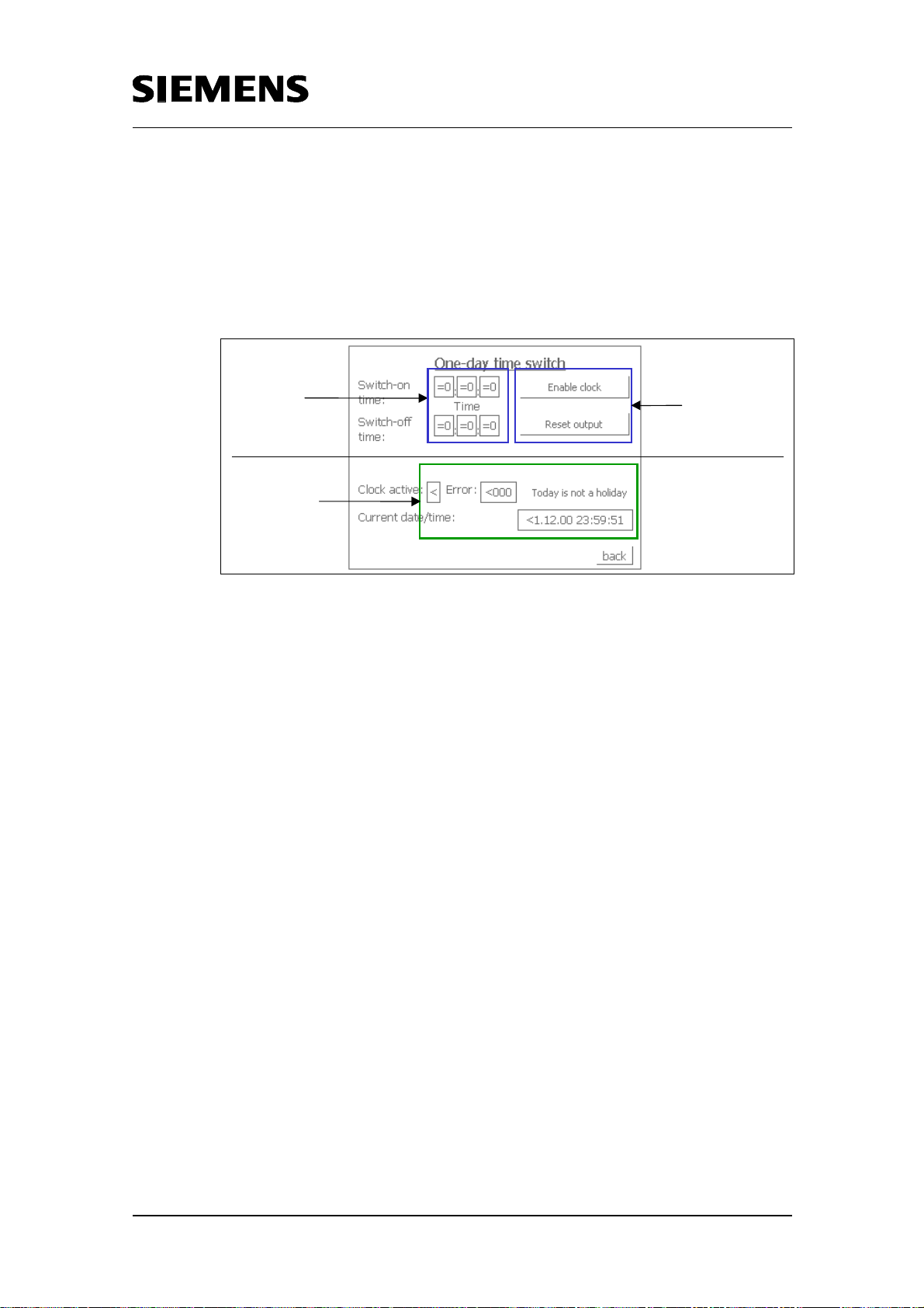
Operating the one-day time switch
The following parameters must be set for the one-day time switches:
• Switch-on times with hour, minute and second
• Switch-off times with hour, minute and second
• Control parameters
The parameterization for the one-day time switch is displayed for one-day
time switch 1 listed above. The same parameterization applies for one-day
time switch 2.
Copyright © Siemens AG 2005 All rights reserved
BID21669756_Zeitschaltuhr_einfach_DOKU_v20_e.doc
Start and
End times
Clock not
aktive
o error
Fig 6-2 Configuration one-day time switch 1
Go back to
overvie w
Clock enabled
Out pu t n o r re se t
Tod a y is n o t a ho liday
Curren t date/time
in the S7 -C PU
Rev. B - final 19.07.2002 57/84
Page 58
Time switch based on the S7-300/400 CPUs with simple HMI system
including radio-controlled clock connection
Operating the seven-day time switch
For the seven-day time switch the following parameters must be set:
• Switch-on time with hour, minute and second as well as the respective
day of the week
• Switch-off time with hour, minute and second as well as the respective
day of the week
• Control parameters
Specifying the day (day of the week):
• 1 to 7 corresponds to Sunday to Saturday
• 8 corresponds to Monday to Friday, i.e. the clock is active every day
from Monday to Friday between switch-on and switch-off time. If the
switch-off time is less than the switch-on time, the clock is active until
Saturday.
Copyright © Siemens AG 2005 All rights reserved
BID21669756_Zeitschaltuhr_einfach_DOKU_v20_e.doc
• 9 corresponds to Saturday to Sunday, i.e. the clock is active every day
from Saturday to Sunday between switch-on and switch-off time. If the
switch-off time is less than the switch-on time, the clock is active until
!
Monday.
Important
The specified switch-on day is always “leading”. This means: If 8 or 9 has been
specified as the start day, the end day must also be 8 or 9. If the start day is
between 1 and 7, the end day must only be between 1 and 7 as well, and not be 8
or 9.
The parameterization for the seven-day time switch is displayed for sevenday time switch 1 listed above. The parameterization for the one-week time
switches 2 and 3 follows the same parameterization as this one.
Rev. B - final 19.07.2002 58/84
Page 59

N
y
N
Time switch based on the S7-300/400 CPUs with simple HMI system
including radio-controlled clock connection
Start and end-times
incl. day or the week
Clock not active
o error
Fig 6-3 Configuration seven-day time switch 1
Go back to
overview
Clock enabled
Output not reset
Today is no t a ho lid a
Current da te /time
in the S7-CPU
Operating the one-month time switch
The following parameters must be set at the one-month time switch:
• Switch-on time with hour, minute and second, and day in the month
• Switch-on time with hour, minute and second, and day in the month
Copyright © Siemens AG 2005 All rights reserved
BID21669756_Zeitschaltuhr_einfach_DOKU_v20_e.doc
• Control parameters
The parameterization for the one-month time switch is displayed for onemonth time switch 1 listed above:
Start and end-time
with day
Clock is not active
o error
Go back to
overview
Clock enabled
Output reset
Today is a ho lid ay
Current da te /ti me
in the S7-CPU
Fig 6-4 Configuration one-month time switch 1
The parameterization of one-month time switch 2 follows the same
parameterization as one-month time switch 1.
Rev. B - final 19.07.2002 59/84
Page 60
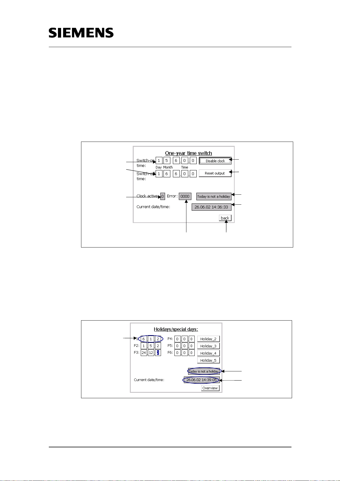
N
y
Time switch based on the S7-300/400 CPUs with simple HMI system
including radio-controlled clock connection
Operating the one-year time switch
The following parameters must be set at the one-year time switch:
• Switch-on time with hour, minute, second, day and month
• Switch-off time with hour, minute, second, day and month
• Control parameters
Copyright © Siemens AG 2005 All rights reserved
BID21669756_Zeitschaltuhr_einfach_DOKU_v20_e.doc
Start and end-time
with day and month
Clock active
o error
Go back to
overview
Clock enabled
Output not re se t
Today is no t a ho lid a
Current da te /ti me
in the S7-CPU
Fig 6-5 Configuration one-year time switch
Operating holidays/special days
Two views are available for entering the holidays/special days. 15
holidays/special days can be entered on each view. Entering a
holiday/special day requires specifying day, month and year.
Input of
day, month, year
for each holiday
Display holiday yes/no
Current date/time
Fig. 6-6 User interface holiday / special day
Rev. B - final 19.07.2002 60/84
Page 61

Time switch based on the S7-300/400 CPUs with simple HMI system
including radio-controlled clock connection
Operating summer/winter time changeover
This user interface offers the possibility to define via a button whether the
changeover is to be performed program controlled, i.e. by FB 103
„summer_winter“, or if the radio-controlled option is to be activated as you
use a radio receiver.
In this application case the radio-controlled option has been activated.
If you do not want to use a radio-controlled clock, switch to the mode
„Program controlled“.
Copyright © Siemens AG 2005 All rights reserved
BID21669756_Zeitschaltuhr_einfach_DOKU_v20_e.doc
Fig. 6-7 User interface summer/winter time changeover
Note
The same clocks can also be operated and monitored with the OP3 (LowCostrange) or with an other HMI device. The TP170A is only given here as an example.
Rev. B - final 19.07.2002 61/84
Page 62
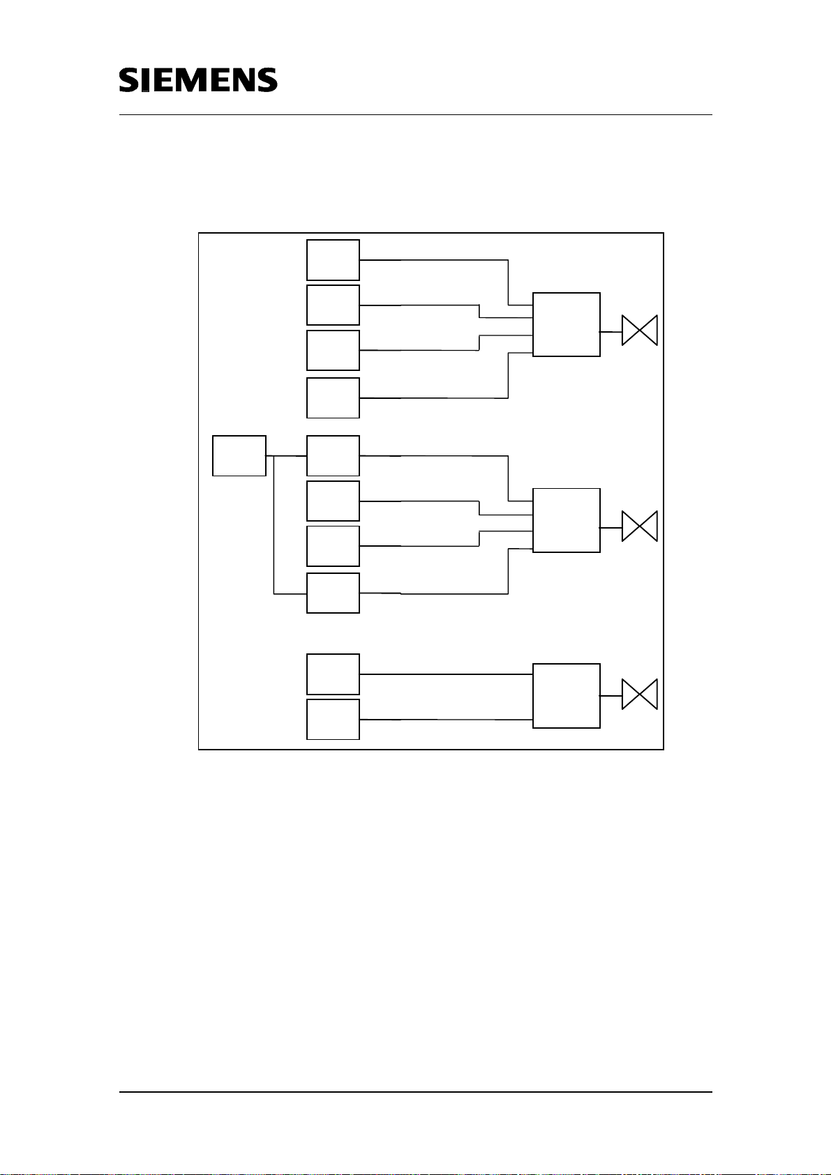
Time switch based on the S7-300/400 CPUs with simple HMI system
including radio-controlled clock connection
Below, an example is illustrated of how the outputs of the individual time
switches are connected in the application case 1. This is for controlling
valves for example.
D1
D2
OR
W2
M1
Copyright © Siemens AG 2005 All rights reserved
BID21669756_Zeitschaltuhr_einfach_DOKU_v20_e.doc
H
W1
D2
OR
M1
On a holiday, the clocks are reset to W 1 an d Y
Y
W3
AND
M2
Fig. 6-8 Example
The following points can be taken from the example:
• The outputs of a clock can be linked several times in the program
• Various outputs of clocks can be linked with an object, for example a
valve.
• Individual clocks can be “switched off” by means of the holiday block.
Rev. B - final 19.07.2002 62/84
Page 63
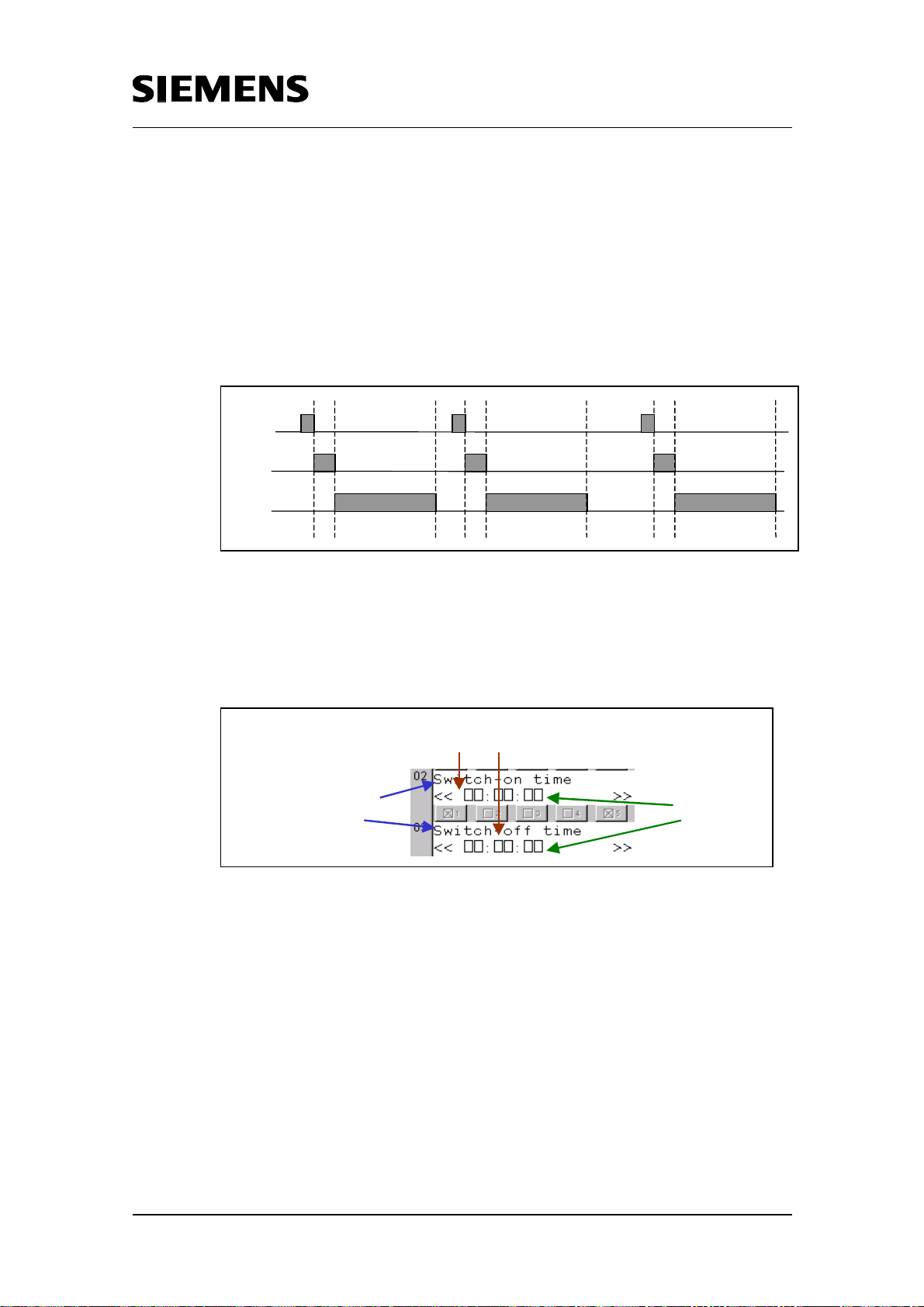
Time switch based on the S7-300/400 CPUs with simple HMI system
including radio-controlled clock connection
6.2 Application case 2: Pulse chain
In this application case a one-day time switch, a seven-day time switch, as
well as 3 relative time switches are used, whereby the 3 relative time
switches make up a pulse chain. This means: Clock 1 switches off -> Off
signal starts clock 2 -> clock 2 switches off -> Off signal starts clock 3. This
is illustrated in the figure below.
Clock
Clock
Clock
Copyright © Siemens AG 2005 All rights reserved
BID21669756_Zeitschaltuhr_einfach_DOKU_v20_e.doc
Fig. 6-9 Pulse diagram “pulse chain”
A view at the OP3 consists of several “windows” A “view” corresponds to 2
lines with 20 possible lines each. The upper line always displays the
explanation on the parameter which can be entered into the bottom line.
„W indow“ at OP 3
Text description of
the parameter
Inp u t/Ou tp u t-
field
Fig. 6-10 Overview OP3 view
The clocks in this application case shall be activated with the following
parameters.
Rev. B - final 19.07.2002 63/84
Page 64

Time switch based on the S7-300/400 CPUs with simple HMI system
including radio-controlled clock connection
Table 6-2 Switching times of the clocks for application case 1
Clock (Time switch) Switching time Clock enabled Output reset
One-day time switch 1
(D)
Seven-day time switch
1 (W)
8:00 to 12:00
a.m.
Fridays from
12:00 to 8:00
Yes Yes
Yes No
p.m.
Relative time switch 1
2 hours Yes No
(R1)
Relative time switch 2
(R2)
Relative time switch 3
5 hours, 30
No No
minutes
1 day, 12 hours Yes Yes
(R3)
Note
In this case unfortunately no “live” views (views with set parameters) can be
illustrated but only those from the configuration view.
Copyright © Siemens AG 2005 All rights reserved
BID21669756_Zeitschaltuhr_einfach_DOKU_v20_e.doc
Rev. B - final 19.07.2002 64/84
Page 65

Time switch based on the S7-300/400 CPUs with simple HMI system
including radio-controlled clock connection
Operating the one-day time switch
The following parameters must be set for the one-day time switches:
• Switch-on times with hour, minute and second
• Switch-off times with hour, minute and second
• Control parameters
Below you see a HMI interface for the one-day time switch in the
configuration view at the OP3:
Enter
start time (8 :0 0 )
Copyright © Siemens AG 2005 All rights reserved
BID21669756_Zeitschaltuhr_einfach_DOKU_v20_e.doc
Enter
end time (12:00)
Enable clock (1)
Clock aktive (0)
Reset
output (1)
0 -> no error
Current d a te /tim e
in the S7-CP U
Holiday/special day
Fig. 6-11 HMI interface for the one-day time switch (configuration view)
Rev. B - final 19.07.2002 65/84
Page 66

Time switch based on the S7-300/400 CPUs with simple HMI system
including radio-controlled clock connection
Operating the seven-day time switch
For the seven-day time switch the following parameters must be set:
• Switch-on time with hour, minute and second as well as the respective
day of the week
• Switch-off time with hour, minute and second as well as the respective
day of the week
• Control parameters
Specifying the day (day of the week):
• 1 to 7 corresponds to Sunday to Saturday
Copyright © Siemens AG 2005 All rights reserved
BID21669756_Zeitschaltuhr_einfach_DOKU_v20_e.doc
• 8 corresponds to Monday to Friday, i.e. the clock is active every day
from Monday to Friday between switch-on and switch-off time. If the
switch-off time is less than the switch-on time, the clock is active until
Saturday.
• 9 corresponds to Saturday to Sunday, i.e. the clock is active every day
from Saturday to Sunday between switch-on and switch-off time. If the
switch-off time is less than the switch-on time, the clock is active until
Monday.
Important
!
The specified switch-on day is always “leading”. This means: If 8 or 9 has been
specified as the start day, the end day must also be 8 or 9. If the start day is
between 1 and 7, the end day must only be between 1 and 7 as well, and not be 8
or 9.
Below you see a HMI interface for the one-week time switch in the
configuration view at the OP3:
Rev. B - final 19.07.2002 66/84
Page 67

Time switch based on the S7-300/400 CPUs with simple HMI system
including radio-controlled clock connection
Enter star t-ti m e
with day of the week
6:00 12:00
Enter en d -ti m e
with day of the week
6:00 20:00
Enable clock (1)
Reset
output (0 )
Copyright © Siemens AG 2005 All rights reserved
BID21669756_Zeitschaltuhr_einfach_DOKU_v20_e.doc
Clock active
0 -> no error
Current time
in the S7 -CPU
Holiday/special day
Fig. 6-12 HMI interface for the seven-day time switch (configuration view)
Rev. B - final 19.07.2002 67/84
Page 68

N
Time switch based on the S7-300/400 CPUs with simple HMI system
including radio-controlled clock connection
Operating the relative time switch
The following parameters must be set for the relative time switch:
• Time_To_Check with days, hours, minutes and seconds
• Control parameters
Below you see a HMI interface for the relative time switch in the
configuration view at the OP3:
Enter time
Copyright © Siemens AG 2005 All rights reserved
BID21669756_Zeitschaltuhr_einfach_DOKU_v20_e.doc
Enable clock
Consider each or only first
edge at input "StartTime"
"1“, if clock aktive
Start-time
Reset if necessary
ot "0“, if error
during processing
Current date/time
in the S7-CPU
Fig. 6-13 HMI interface for the relative time switch (configuration view)
Note
The same clocks can also be operated and monitored with TP170A or with an
other HMI device. The OP3 is only given here as an example.
Rev. B - final 19.07.2002 68/84
Page 69

Time switch based on the S7-300/400 CPUs with simple HMI system
including radio-controlled clock connection
Below, an example is illustrated of how the outputs of the individual time
switches are connected in the application case 2. For example: Valves are
controlled.
R1
R2
R3
Copyright © Siemens AG 2005 All rights reserved
BID21669756_Zeitschaltuhr_einfach_DOKU_v20_e.doc
D
OR
W
R1
R2
R3
D
OR
W
Fig. 6-14 Example
The following points can be taken from the example:
• The outputs of a clock can be linked several times in the program.
• Various outputs of clocks can be linked with an object, for example a
valve.
Rev. B - final 19.07.2002 69/84
Page 70

Time switch based on the S7-300/400 CPUs with simple HMI system
including radio-controlled clock connection
Part C: Program Description
Objectives of Part C:
The purpose of this section is to
Explain the code details of some core elements in the program
Suggest where it might usefully be expanded
Requirements
This is not an introduction to the STEP 7 STL language. Readers should be
familiar with the basics of these languages.
Before reading the description of the code, it may be useful to read the
chapters in parts A1 and A2.
Copyright © Siemens AG 2005 All rights reserved
BID21669756_Zeitschaltuhr_einfach_DOKU_v20_e.doc
Rev. B - final 19.07.2002 70/84
Page 71

Time switch based on the S7-300/400 CPUs with simple HMI system
including radio-controlled clock connection
7 STEP 7 Program
The STEP 7 code will not be explained here line by line. This
documentation will focus on the core points. Detailed information on the
programs may be found in the appropriate sources.
7.1 Absolute time switches
7.1.1 Seven-day time switch
For the seven-day time switch (FB121) it must be checked whether the
function Monday to Friday or Saturday to Sunday has been entered at the
start day. If yes, the same function must be entered at the end day and the
time must be checked specifically.
Table 7-1 Code seven-day time switch
Copyright © Siemens AG 2005 All rights reserved
BID21669756_Zeitschaltuhr_einfach_DOKU_v20_e.doc
Code Remarks
NETWORK 3:
// function: mo - fr?
L #time_to_check.startday
L 8
==I
SPB s8
// function: sa - su?
L #time_to_check.startday
L 9
==I
SPB s9
L 8
L #time_to_check.endday
==I
SPB err
L 9
==I
SPB err
SPA ess
Function equal Monday to Friday
Function equal Saturday to
Sunday
If function at end day equals Mo
– Fr oder Sa – Su then error and
end
7.1.2 One-month time switch
At the month time switch (FB123) it must be checked whether the function
“last day in the month” is used. If yes, the start day of the end day must be
set to the last day of the respective month.
Rev. B - final 19.07.2002 71/84
Page 72

Time switch based on the S7-300/400 CPUs with simple HMI system
including radio-controlled clock connection
Table 7-2 Code one-month time switch
Code Remarks
Copyright © Siemens AG 2005 All rights reserved
BID21669756_Zeitschaltuhr_einfach_DOKU_v20_e.doc
NETZWERK 4:
enst: NOP 0
L #time_to_check.start_dateday
T #temp_startday
L #time_to_check.end_dateday
T #temp_endday
L #temp_startday
L 32
==I
SPB mola
L #temp_endday
L 32
==I
SPB mola
SPA equa
NETWORK 5:
mola: NOP 0
L #month
SPL nomo
SPA ende
SPA m31
SPA m28
SPA m31
SPA m30
SPA m31
SPA m30
SPA m31
SPA m31
SPA m30
SPA m31
SPA m30
SPA m31
nomo: SPA ende
NETWORK 6:
m31: NOP 0
L #temp_startday
L 32
<>I
SPB m2
L 31
T #temp_startday
m2: NOP 0
L #temp_endday
L 32
<>I
SPB equa
L 31
T #temp_endday
SPA equa
Check whether the Function”
“Last day of the month” has been
specified in the start day of in the
end day.
If yes, check current month
If e.g. month with 31 days, set
start day or end day to 31
(depending on where the
“Function” “Last day in the
month” is required)
Same function also exists for
months with 30 days or with 28
days
Rev. B - final 19.07.2002 72/84
Page 73

Time switch based on the S7-300/400 CPUs with simple HMI system
including radio-controlled clock connection
7.2 Relative time switch
For the relative time switch (FB124) the correct evaluation of the individual
inputs is important. Depending on whether the clock will be active, whether
the time to elapse restarts at every edge or only at the first edge.
Table 7-3 Code relative time switch
Code Remarks
Copyright © Siemens AG 2005 All rights reserved
BID21669756_Zeitschaltuhr_einfach_DOKU_v20_e.doc
NETWORK 1:
L 0
T #err
UN #start
SPB next
UN #checkflank
SPB n2
SPA flan
n2: NOP 0
U #Q
SPB next
flan: NOP 0
U #enable
FP #startenable
= #impuls
UN #impuls
SPB next
Clock not enabled-> check
whether still active and needs to
be switched off
Only the first edge is reacted to
If output still active -> reset
output, otherwise
check whether new positive edge
at the input “Enable“
Rev. B - final 19.07.2002 73/84
Page 74
Time switch based on the S7-300/400 CPUs with simple HMI system
including radio-controlled clock connection
7.3 Special functions
The special functions “Summer/winter time changeover” and “Holidays” are
briefly discussed below.
7.3.1 Summer/wintertime changeover
For the summer/winter time changeover this application offers a programcontrolled changeover. Optionally, this time changeover can be performed
by a radio-controlled clock module (compare user interface for
summer/winter time changeover, fig. 6-7).
Standard: Program-controlled time changeover
The time changeover takes place at the last Sunday in March or
respectively at the last Sunday in October. It is checked by the block by
reading the current date/time from the S7.CPU (FB103).
Copyright © Siemens AG 2005 All rights reserved
BID21669756_Zeitschaltuhr_einfach_DOKU_v20_e.doc
Table 7-4 Configuration summer/winter time changeover (program-controlled)
Code Remarks
NETWORK 3:
L #actdate.actdayofweek // if current day of the week
sunday,
L 1
<>I
R #SetEdge
BEB // nothing -> end
L #actdate.actmonth // current month == March,
L 3
==I
SPB mrz // goto check, if it is the last sunday
L #actdate.actmonth // current month == October
L 10
==I
SPB okt // goto check, if it is the last sunday
BEA
.
.
.
Check whether today is Sunday
Check whether it is the last
Sunday in March
Check whether it is the last
Sunday in October
Option: Radio-controlled time changeover
In this case the block FB77 „DCF77_FB“ is being called instead of FB103
„summer_winter“. FB77 evaluates the signals sent by the radio-controlled
clock. The block is know-how protected, therefore only the call of the block
and the parameterization are shown below.
Rev. B - final 19.07.2002 74/84
Page 75
Time switch based on the S7-300/400 CPUs with simple HMI system
including radio-controlled clock connection
Table 7-5 Configuration summer/winter time changeover (radio-controlled)
Code Remarks
NETWORK 9:
CALL "DCF77_FB" , "DCF77_IDB"
SekTakt :=SecClockDCF
Data :=DataDCF
SekCPU :=1HzPulse
DCF77 :="DCF77_Timer"
Zeitzone :="TimeZone"
Umsch_Zeitzone:="SwitchTimeZoneIn1Hour"
Min_Puls :="Min_Pulse"
Fehler :="ErrorDCF77"
Input „second clock pulse“ of DCF module
Input “data” of DCF module
Clock memory byte in the CPU
Timing element for DCF77 evaluation
1=summertime 0=wintertime
1= in 1h switch from summer to wintertime
or from winter to summertime
with this pulse a new minute begins and the
clock is being set
1= for longer than 3 minutes no valid
telegram has been received
7.3.2 Holidays/special days
The block FC 100 checks in a loop whether a date in the DB with the
holidays and special days is identical with the current date.
Copyright © Siemens AG 2005 All rights reserved
BID21669756_Zeitschaltuhr_einfach_DOKU_v20_e.doc
Rev. B - final 19.07.2002 75/84
Page 76

Time switch based on the S7-300/400 CPUs with simple HMI system
including radio-controlled clock connection
Table 7-5 Code holidays/special days
Code Remarks
Copyright © Siemens AG 2005 All rights reserved
BID21669756_Zeitschaltuhr_einfach_DOKU_v20_e.doc
NETZWERK 2:
.
.
schl: T #zaehler
L #jahr
L DBW [#index]
<>I
SPB jnex
L #index
SRW 3
L 2
+I
SLW 3
T #index
L #monat
L DBW [#index]
<>I
SPB mnex
L #index
SRW 3
L 2
+I
SLW 3
T #index
L #tag
L DBW [#index]
<>I
SPB tnex
SET
S #feiertag
BEA
Check whether year in the DB
coincides with the current year
Increase index
Check whether month in the DB
coincides with the current month
Increase index
Check whether day in the DB
coincides with the current day
Rev. B - final 19.07.2002 76/84
Page 77
Time switch based on the S7-300/400 CPUs with simple HMI system
including radio-controlled clock connection
8 HMI Interface
There are no scripts in the HMI configuration. The views are explained in
detail in Chapter 6. Therefore this chapter is kept very short.
9 Changes in the STEP 7 Programs
The steps to be performed to adapt the application to your requirements
are listed below. These include:
• What to do if a second time switch of the same type is needed? (Chapter
9.1)
• How can I get several switch-on/off times into one block? (Chapter 9.2)
• What to do if more holidays or special days are needed? (Chapter 9.3)
• How can I save on Instance DBs? (Chapter 9.4)
Copyright © Siemens AG 2005 All rights reserved
BID21669756_Zeitschaltuhr_einfach_DOKU_v20_e.doc
9.1 What to do if a second time switch of the same type is needed?
The respective FB must be called a second time with new parameters.
Table 9-1 Second time switch of the same type
Step Instruction Note / Instruction
Open the block from which the time
1
function is to be called, e.g. OB1.
Call the time function twice and supply
2
the interface with your parameters.
Note:
The parameters are assigned to data
areas, which have the structure of the
required UDT.
3 Save
4
Choose PLC -> Download
Or download symbol
Rev. B - final 19.07.2002 77/84
Page 78
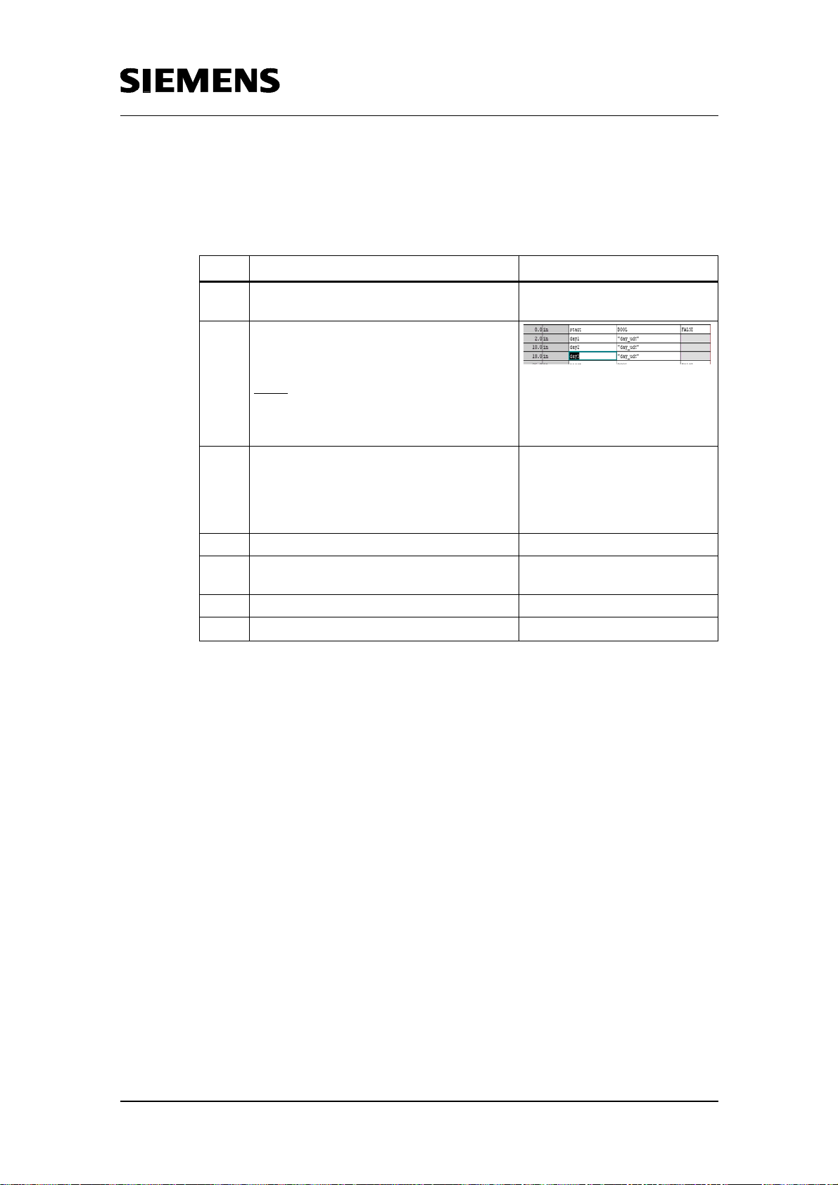
Time switch based on the S7-300/400 CPUs with simple HMI system
including radio-controlled clock connection
9.2 How can I get several switch-on/off times into one time switch block?
Table 9-2 Several switch-on/off times in one block
Step Instruction Note / Instruction
Create a new FB in the block container of
1
the SIMATIC Manager and open it.
Create as many input parameters of the
2
respective UDT as switch-on/off times
are required (e.g. 3).
Note:
On calling, link the input parameters of
the new FB with the data areas which
have the structure of the required UDT.
Call the FB for the respective time
3
function (depending on which UDT you
used) as often as a respective input
parameter has been configured in the
instruction section of the new FB.
4 Save the newly created FB.
Now call this FB in your user program
5
e.g. OB1.
7 Save
8
Choose PLC -> Download
Or download symbol
Copyright © Siemens AG 2005 All rights reserved
BID21669756_Zeitschaltuhr_einfach_DOKU_v20_e.doc
Rev. B - final 19.07.2002 78/84
Page 79
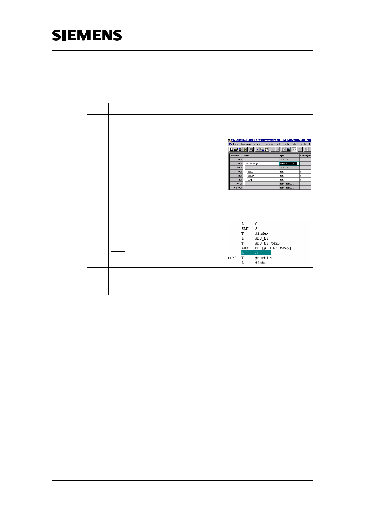
Copyright © Siemens AG 2005 All rights reserved
BID21669756_Zeitschaltuhr_einfach_DOKU_v20_e.doc
Time switch based on the S7-300/400 CPUs with simple HMI system
including radio-controlled clock connection
9.3 What to do if more holidays or special days are needed?
Table 9-3 More holidays/special days
Step Instruction Note / Instruction
Open the DB in which the holidays and
1
special days are stored (DB100 in this
example)
Increase the number of Array elements to
2
the desired number (default value 30)
3 Save the DB.
Open the FC which checks the holidays
4
(FC100 in this example).
Increase the loop count. The loop count
5
must be as high as the number of array
elements
Note:
The code sequence is available in the
network 2 of the block.
7 Save the FC.
8
Load the block via PLC -> Download im
SIMATIC Manager.
Or download symbol
Rev. B - final 19.07.2002 79/84
Page 80
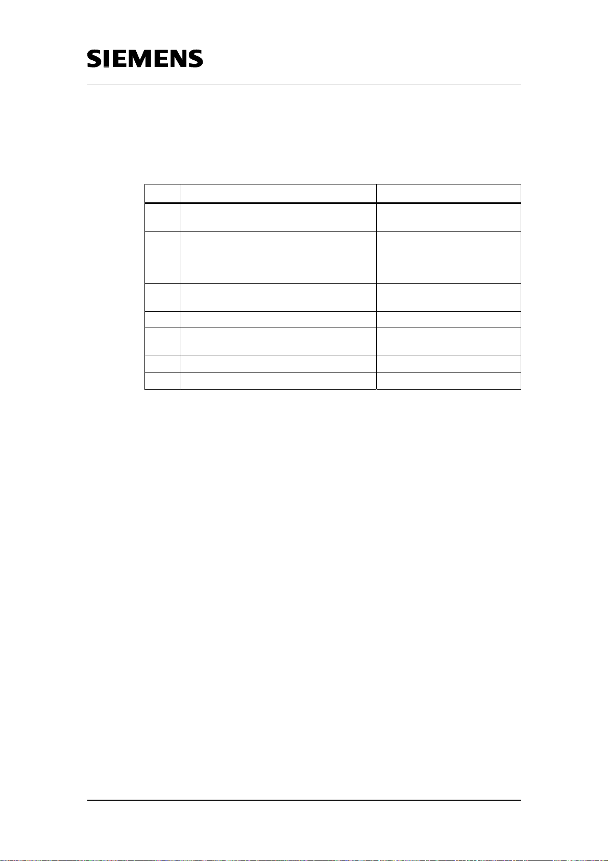
Time switch based on the S7-300/400 CPUs with simple HMI system
including radio-controlled clock connection
9.4 How can I save on Instance DBs?
Table 9-4 Saving on Instance-DBs
Step Instruction Note / Instruction
Create a new FB in the block container of
1
the SIMATIC Manager and open it.
Create static variables (instances). The
2
type of the static variable corresponds to
the time function for the one-day time
switch e.g. FB120.
Call the instances in the block as often as
3
the time functions are required.
4 Save the newly created FB.
Now call this FB in your user program
5
e.g. OB1.
7 Save
8
Choose PLC -> Download
Or download symbol
Copyright © Siemens AG 2005 All rights reserved
BID21669756_Zeitschaltuhr_einfach_DOKU_v20_e.doc
Further information on so-called multi-instances are also available in the
STEP 7 online-help.
Rev. B - final 19.07.2002 80/84
Page 81

Time switch based on the S7-300/400 CPUs with simple HMI system
including radio-controlled clock connection
Appendix: Connection of the SICLOCK radio clock
Introduction
Within the scope of the present application, the SIPLUS radio clock was
used.
A viable alternative is the use of the SICLOCK radio clock. This appendix
describes the SICLOCK features in a concise from. These features are
grouped as follows:
• Functionality
• Basic performance data
• Hardware components
• Hardware connection
• Software interface and block parameterization
Copyright © Siemens AG 2005 All rights reserved
BID21669756_Zeitschaltuhr_einfach_DOKU_v20_e.doc
These points are addressed below.
Functionality
The SICLOCK radio clock features the same principal functionality as
SIPLUS. It is used for reception of the DCF77 time signal transmitter, the
signal of which is demodulated and provided as an impulse for the S7. The
software supplied synchronizes the S7-CPU system time with the official
time received.
Basic performance data
The basic performance data of the SICLOCK DCF77 radio receiver are as
follows:
Frequency 77.5kHz
Band width 400 Hz
Dimensions
Sensitivity
(W x H x D) 185 x 80 x 65 mm
0.3 µV
Connection cable 20 m, firmly attached
Connector type 9 pole SUBD
Power supply via RS232 interface
Operating temperature -10 °C to +50 °C
Protection type IP65
:
Rev. B - final 19.07.2002 81/84
Page 82

Time switch based on the S7-300/400 CPUs with simple HMI system
including radio-controlled clock connection
Hardware components
The following hardware components are required for connection to S7-300:
Component Order number Description/View
SICLOCK DCFRS 2XV9450-1AR06 DCF77 receiver
Copyright © Siemens AG 2005 All rights reserved
BID21669756_Zeitschaltuhr_einfach_DOKU_v20_e.doc
9 pole DSUB connector
2XV9450-1AR35 For connection to SIMATIC
with 5m connection cable
Optocoupler 3TX7-005-3PB54
The following figure shows a complete schematic hardware configuration
with SICLOCK radio clock:
Radio clock
Optocoupler
Rev. B - final 19.07.2002 82/84
Page 83

Time switch based on the S7-300/400 CPUs with simple HMI system
including radio-controlled clock connection
Hardware connection
Wiring the SICLOCK radio clock module to the power supply / SM 321 is
made as follows:
PS SM 321 SICLOCK
E 0.3 Yellow (received signal)
M Grey (cable screen)
L+ Green (supply voltage)
M Brown (signal and supply ground)
For amplifying the SICLOCK transmitter signal, using an optocoupler may
be required. In this case wiring is made according to the scheme below:
Copyright © Siemens AG 2005 All rights reserved
BID21669756_Zeitschaltuhr_einfach_DOKU_v20_e.doc
SIMATIC S7
Optocoupler SICLOCK
PS SM
+13 24Vdc
Green (supply voltage)
Mass
A2
0V
Brown (signal and supply ground)
Grey (cable screen)
E 0.3 14
A1 Yellow (received signal)
Important note
The radio clock module should be positioned so that the radio signal is not shielded
by building facades of metal or similar obstacles. The module itself must be
shielded from interference frequencies and should not be positioned directly on a
metal surface.
Rev. B - final 19.07.2002 83/84
Page 84

Time switch based on the S7-300/400 CPUs with simple HMI system
including radio-controlled clock connection
Software interface and block parameterization
Along with the hardware, a disk is supplied that contains all S7 blocks
necessary for the SICLOCK DCF77 reception service. These are: FB100,
DB100, SFC0, SFC39, SFC40, FC34
These blocks have to be included in the blocks folder of your S7 project.
The call of the FB100 function block has to be made in the following blocks:
• OB 1
• OB 100 (Startup OB)
• OB 35 (timed alarm 10 ms):
Parameterization follows the table below:
Copyright © Siemens AG 2005 All rights reserved
BID21669756_Zeitschaltuhr_einfach_DOKU_v20_e.doc
Call
OB1 OB100 OB35
in
Additional information:
Additional information on the SICLOCK DCF receiver is available for download
from http://www.siclock.de/, and in the operating and installation instructions
supplied with the hardware.
Rev. B - final 19.07.2002 84/84
 Loading...