

Siemens SIMATIC S7-300,SIMATIC S7-300 CPU Data: CPU 315-T-2 DP User Manual

_
_
_
_
_
_
_
_
_
_
SIMATIC S7-300 S7-300 CPU Data: CPU 315T-2 DP
Preface
_____________
Product Overview
_____________
1
2
SIMATIC
S7-300
S7-300 CPU Data: CPU 315T-2 DP
Manual
Operator controls and
indicators
_____________
Setting up an S7-300 with a
Technology CPU
_____________
Communication with the
S7-300
_____________
Memory concept
_____________
Cycle and response times
_____________
Technical data
_____________
Information for the
Changeover to the
_____________
Technology CPU
3
4
5
6
7
8
9
Appendix A
_____________
A
12/2005
A5E00427933-02

Safety Guidelines
This manual contains notices you have to observe in order to ensure your personal safety, as well as to prevent
damage to property. The notices referring to your personal safety are highlighted in the manual by a safety alert
symbol, notices referring only to property damage have no safety alert symbol. These notices shown below are
graded according to the degree of danger.
Danger
indicates that death or severe personal injury
Warning
indicates that death or severe personal injury
Caution
with a safety alert symbol, indicates that minor personal injury can result if proper precautions are not taken.
will result if proper precautions are not taken.
may result if proper precautions are not taken.
Caution
without a safety alert symbol, indicates that property damage can result if proper precautions are not taken.
Notice
indicates that an unintended result or situation can occur if the corresponding information is not taken into
account.
If more than one degree of danger is present, the warning notice representing the highest degree of danger will
be used. A notice warning of injury to persons with a safety alert symbol may also include a warning relating to
property damage.
Qualified Personnel
The device/system may only be set up and used in conjunction with this documentation. Commissioning and
operation of a device/system may only be performed by qualified personnel. Within the context of the safety notes
in this documentation qualified persons are defined as persons who are authorized to commission, ground and
label devices, systems and circuits in accordance with established safety practices and standards.
Prescribed Usage
Note the following:
Warning
This device may only be used for the applications described in the catalog or the technical description and only in
connection with devices or components from other manufacturers which have been approved or recommended
by Siemens. Correct, reliable operation of the product requires proper transport, storage, positioning and
assembly as well as careful operation and maintenance.
Trademarks
All names identified by ® are registered trademarks of the Siemens AG. The remaining trademarks in this
publication may be trademarks whose use by third parties for their own purposes could violate the rights of the
owner.
Disclaimer of Liability
We have reviewed the contents of this publication to ensure consistency with the hardware and software
described. Since variance cannot be precluded entirely, we cannot guarantee full consistency. However, the
information in this publication is reviewed regularly and any necessary corrections are included in subsequent
editions.
Siemens AG
Automation and Drives
Postfach 48 48
90437 NÜRNBERG
GERMANY
Order No.: A5E00427933-02
Edition 12/2005
Copyright © Siemens AG .
Technical data subject to change

Table of contents
1 Preface ................................................................................................................................................... 1-1
2 Product Overview ................................................................................................................................... 2-1
3 Operator controls and indicators............................................................................................................. 3-1
4 Setting up an S7-300 with a Technology CPU........................................................................................ 4-1
4.1 Overview .................................................................................................................................... 4-1
4.2 S7-300 components................................................................................................................... 4-1
4.3 Configuring................................................................................................................................. 4-2
4.4 Subnets...................................................................................................................................... 4-2
4.4.1 Expanding and Networking Subnets.......................................................................................... 4-2
4.4.2 Interfaces ................................................................................................................................... 4-3
4.5 Addressing ................................................................................................................................. 4-4
4.6 Commissioning........................................................................................................................... 4-5
4.7 Operating system....................................................................................................................... 4-6
4.8 Status and error displays of the Technology CPU..................................................................... 4-6
5 Communication with the S7-300............................................................................................................. 5-1
5.1 Interfaces ................................................................................................................................... 5-1
5.1.1 Overview .................................................................................................................................... 5-1
5.1.2 MPI/DP interface (X1) ................................................................................................................ 5-1
5.1.3 PROFIBUS DP(DRIVE) interface (X3) ...................................................................................... 5-3
5.2 DPV1 (X1 only as PROFIBUS DP interface)............................................................................. 5-4
5.3 Communication services on the MPI/DP interface (X1)............................................................. 5-6
5.3.1 Overview of communication services ........................................................................................ 5-6
5.3.2 PG communication..................................................................................................................... 5-7
5.3.3 OP communication..................................................................................................................... 5-7
5.3.4 S7 basic communication ............................................................................................................ 5-8
5.3.5 S7 communication ..................................................................................................................... 5-8
5.3.6 Global data communication ....................................................................................................... 5-9
5.3.7 Routing..................................................................................................................................... 5-10
5.3.8 Data consistency...................................................................................................................... 5-13
5.4 S7 communication structure .................................................................................................... 5-13
5.4.1 Communication path of an S7 connection ............................................................................... 5-13
5.4.2 Assignment of S7 connections................................................................................................. 5-14
5.4.3 Distribution and availability of S7 connection resources ......................................................... 5-16
6 Memory concept ..................................................................................................................................... 6-1
6.1 Memory areas and retentive address areas .............................................................................. 6-1
6.1.1 Technology CPU memory areas................................................................................................ 6-1
6.1.2 Retentive address areas of the load memory, system memory and technology system data .. 6-2
6.1.3 Retentive behavior of the memory objects ................................................................................ 6-3
S7-300 CPU Data: CPU 315T-2 DP
Manual, 12/2005, A5E00427933-02
iii

Table of contents
6.1.4 Address areas of system memory ............................................................................................. 6-4
6.1.5 Properties of the Micro Memory Card (MMC)............................................................................ 6-7
6.1.6 Saving/retrieving whole projects to/from the Micro Memory Card ............................................. 6-8
6.2 Memory functions..................................................................................................................... 6-10
6.2.1 Downloading the user program................................................................................................ 6-10
6.2.2 Downloading a user program (enhanced handling)................................................................. 6-11
6.2.3 CPU memory reset and restart ................................................................................................ 6-12
6.3 Recipes .................................................................................................................................... 6-13
6.4 Measured value log files .......................................................................................................... 6-15
6.5 Technology data blocks ........................................................................................................... 6-17
6.6 Memory of the integrated technology of the CPU.................................................................... 6-17
7 Cycle and response times....................................................................................................................... 7-1
7.1 Overview .................................................................................................................................... 7-1
7.2 Cycle time................................................................................................................................... 7-2
7.2.1 Overview .................................................................................................................................... 7-2
7.2.2 Calculating the cycle time .......................................................................................................... 7-4
7.2.3 Different cycle times................................................................................................................... 7-5
7.2.4 Communication Load ................................................................................................................. 7-6
7.2.5 Cycle time extension as a result of testing and commissioning functions ................................. 7-8
7.3 Response time ........................................................................................................................... 7-8
7.3.1 Overview .................................................................................................................................... 7-8
7.3.2 Shortest response time ............................................................................................................ 7-10
7.3.3 Longest response time............................................................................................................. 7-11
7.3.4 Reducing the response time with direct I/O access................................................................. 7-13
7.4 Calculating method for calculating the cycle/response time.................................................... 7-13
7.5 Interrupt response time ............................................................................................................ 7-14
7.5.1 Overview .................................................................................................................................. 7-14
7.5.2 Reproducibility of Time-Delay and Watchdog Interrupts ......................................................... 7-16
7.6 Sample calculations ................................................................................................................. 7-16
7.6.1 Calculation example for the cycle time of the CPU 315T-2 DP ............................................... 7-16
7.6.2 Calculation example for the response time of the CPU 315T-2 DP ........................................ 7-17
7.6.3 Calculation example for the interrupt response time of the CPU 315T-2 DP .......................... 7-19
8 Technical data ........................................................................................................................................ 8-1
8.1 General technical data ............................................................................................................... 8-1
8.1.1 Dimension drawing..................................................................................................................... 8-1
8.1.2 Technical specifications of the Micro Memory Card (MMC) ...................................................... 8-2
8.1.3 Clock .......................................................................................................................................... 8-2
8.2 CPU 315T-2 DP ......................................................................................................................... 8-3
8.3 Integrated Inputs/Outputs for Technology.................................................................................. 8-9
8.3.1 Arrangement of integrated inputs/outputs for integrated technology......................................... 8-9
8.3.2 Technical specifications of digital inputs.................................................................................. 8-10
8.3.3 Technical specifications of digital outputs................................................................................ 8-12
9 Information for the Changeover to the Technology CPU......................................................................... 9-1
9.1 Scope ......................................................................................................................................... 9-1
9.2 Changed behavior of certain SFCs............................................................................................ 9-2
9.3 Interrupt events from distributed I/Os while the CPU status is in STOP.................................... 9-3
S7-300 CPU Data: CPU 315T-2 DP
iv Manual, 12/2005, A5E00427933-02

Table of contents
9.4 Runtimes that change while the program is running ................................................................. 9-4
9.5 Converting the diagnostic addresses of DP slaves ................................................................... 9-4
9.6 Reusing existing hardware configurations ................................................................................. 9-5
9.7 Replacement of a Technology CPU .......................................................................................... 9-5
9.8 Using consistent data areas in the process image for DP slaves.............................................. 9-5
9.9 Load memory design for the Technology CPU.......................................................................... 9-5
9.10 Altered retentive response with a Technology CPU .................................................................. 9-6
9.11 FMs/CPs with their own MPI address in a Technology CPU rack............................................. 9-6
9.12 Information about interface X3 DP(DRIVE) ............................................................................... 9-7
A Appendix A .............................................................................................................................................A-1
A.1 List of abbreviations ................................................................................................................... A-1
Glossary ..................................................................................................................................... Glossary-1
Index................................................................................................................................................ Index-1
Tables
Table 1-1 Scope of this manual .................................................................................................................
1-1
Table 1-2 Documentation for the Technology CPU ................................................................................... 1-2
Table 1-3 Additional documentation for the Technology CPU................................................................... 1-3
Table 3-1 Operator controls and indicators of the Technology CPU ......................................................... 3-1
Table 3-2 Integrated technology inputs and outputs on the Technology CPU .......................................... 3-2
Table 3-3 Switch positions of the mode selector switch ............................................................................ 3-3
Table 3-4 Status and error displays of the CPU ........................................................................................ 3-3
Table 4-1 S7-300 components................................................................................................................... 4-2
Table 4-2 Subnet nodes............................................................................................................................. 4-3
Table 4-3 Possible operating modes of interfaces on the Technology CPU ............................................. 4-4
Table 4-4 Connectable devices.................................................................................................................. 4-4
Table 4-5 Status and error displays of the Technology CPU..................................................................... 4-6
Table 4-6 LEDs BF1 and BF3 .................................................................................................................... 4-7
Table 4-7 LED BF1 illuminated .................................................................................................................. 4-8
Table 4-8 ED BF1 flashes .......................................................................................................................... 4-8
Table 4-9 LED BF3 illuminated .................................................................................................................. 4-8
Table 4-10 LED BF3 flashes ........................................................................................................................ 4-8
Table 5-1 Interrupt blocks with DPV1 functionality .................................................................................... 5-5
Table 5-2 System function blocks with DPV1 functionality ........................................................................ 5-5
Table 5-3 CPU communication services .................................................................................................... 5-6
Table 5-4 GD resources of the CPU .......................................................................................................... 5-9
Table 5-5 Distribution of the S7 connections ........................................................................................... 5-16
S7-300 CPU Data: CPU 315T-2 DP
Manual, 12/2005, A5E00427933-02
v

Table of contents
Table 5-6 Availability of the S7 connections for the CPU 315T-2 DP ...................................................... 5-16
Table 6-1 Retentive behavior of the memory objects................................................................................. 6-3
Table 6-2 Retentive behavior of the DBs for the Technology CPU............................................................ 6-4
Table 6-3 Address areas of system memory ............................................................................................. 6-4
Table 6-4 Plug-in MMCs............................................................................................................................. 6-7
Table 7-1 Cyclic program processing......................................................................................................... 7-2
Table 7-2 Data for calculating the process image (PI) transfer time.......................................................... 7-4
Table 7-3 Increase in cycle time by nesting interrupts ............................................................................... 7-5
Table 7-4 Cycle time extension as a result of errors.................................................................................. 7-5
Table 7-5 Cycle time extension as a result of testing and commissioning functions ................................. 7-8
Table 7-6 Calculating the response time.................................................................................................. 7-14
Table 7-7 Process/diagnostic interrupt response times ........................................................................... 7-14
Table 7-8 Process/diagnostic interrupt response times ........................................................................... 7-15
Table 8-1 Available MMCs ......................................................................................................................... 8-2
Table 8-2 Features and functions of the clock ........................................................................................... 8-2
Table 8-3 Technical data for the CPU 315T-2 DP ..................................................................................... 8-3
Table 8-4 Technical specifications of the integrated inputs for integrated technology ............................ 8-10
Table 8-5 Technical specifications of the integrated outputs for integrated technology .......................... 8-12
Table 9-1 CPUs previously used................................................................................................................ 9-1
Table 9-2 Behavior of FMs/CPs with their own MPI address..................................................................... 9-6
Table A-1 List of abbreviations ................................................................................................................... A-1
S7-300 CPU Data: CPU 315T-2 DP
vi Manual, 12/2005, A5E00427933-02

Preface
Purpose of this manual
This manual contains all the necessary information for the installation, the communication
functions, the memory concept, the cycle and response times as well as the technical
specifications of the Technology CPU. You will then learn the points to consider when
upgrading to the CPU discussed in this manual.
Required basic knowledge
Knowledge required to understand this manual:
• General knowledge of automation
• Knowledge of motion control
• Knowledge of the STEP 7 basic software.
For further information, refer to the
Scope of this manual
This manual is valid for the following CPU with the following firmware and hardware
versions:
Programming with STEP 7 V5.3
1
manual.
Table 1-1 Scope of this manual
CPU Order number
CPU 315T-2 DP 6ES7 315-6TG10-0AB0 V2.4/V3.2 02
This manual describes the properties and differences of the Technology CPU compared with
the installation manual,
and CPU 31x
Note
This manual contains the descriptions of all current modules.
For new modules, or modules of a more recent version, we reserve the right to include a
Product Information containing latest information.
S7-300 CPU Data: CPU 315T-2 DP
Manual, 12/2005, A5E00427933-02
As of version
Firmware Hardware
S7-300 Automation Systems: Hardware and Installation: CPU 31xC
.
1-1
Preface
Approvals
The SIMATIC S7-300 product series has the following approvals:
• Underwriters Laboratories, Inc.: UL 508 (Industrial Control Equipment)
• Canadian Standards Association: CSA C22.2 No. 142 (Process Control Equipment)
• Factory Mutual Research: Approval Standard Class Number 3611
CE marking
The SIMATIC S7-300 product series satisfies the requirements and safety specifications of
the following EC directives:
• EC Directive 73/23/EEC "Low-voltage directive"
• EC Directive 89/336/EEC "EMC Directive"
C-tick mark
The SIMATIC S7-300 product series is compliant with AS/NZS 2064 (Australia and New
Zealand).
Standards
The SIMATIC S7-300 product series is compliant with IEC 61131-2.
The Technology CPU is oriented to the planned standards for PLCopen V2.0 and
PROFIdrive V3.0.
Documentation classification
This manual is part of the Technology CPU documentation package.
All of these manuals are available as electronic manuals on the CD-ROM of the
Technology
Table 1-2 Documentation for the Technology CPU
Title Contents
Getting Started
CPU 317T-2 DP: Controlling a SINAMICS S120
CPU 317T-2 DP: Controlling a physical axis
CPU 317T-2 DP: Controlling a virtual axis
CPU Data Reference Manual
→
CPU data: CPU 315T-2 DP
(you are reading this manual)
CPU data:CPU 317T-2 DP
Manual
S7-Technology
option package.
The example used in these Getting Started manuals guides
you through the various steps in commissioning required to
obtain a fully functional application.
Description of the operation, functions and technical
specifications of the CPU 315T-2 DP and CPU 317T-2 DP
Description of the individual technological functions:
• Application and benefits
• Fundamentals and configuration
• Loading, testing and diagnostics
• PLCopen functions
S7-
S7-300 CPU Data: CPU 315T-2 DP
1-2 Manual, 12/2005, A5E00427933-02
Preface
Title Contents
Software Installation Manual
S7-300 Automation Systems:
Installation: CPU 31xC and CPU 31x
Module Data Reference Manual
S7-300 Automation Systems:Module Data
Instruction List
CPU 31xC, CPU 31x
IM 151-7 CPU, BM 147-1 CPU, BM 147-2 CPU
Description of the configuration, installation, wiring,
networking and commissioning of an S7-300
Technical data and descriptions of the functions of signal
modules, power supply modules and interface modules
List of the CPU operation set and their execution times. List
of the executable blocks (OBs/SFCs/SFBs) and their
execution times
In addition to this documentation package, you require the following manual:
Table 1-3 Additional documentation for the Technology CPU
System Software for S7-300/400, System and Standard
Functions reference manual
The reference manual is part of the STEP 7
documentation package
Further support
Do you have more questions about using the products described in the manual? Then
contact the Siemens representative or office nearest you.
http://www.siemens.com/automation/partner
Training center
SIEMENS offers a range of courses to help you to get started with your S7-300 automation
system. Please contact your regional Training Center, or the central Training Center in D90327 Nuremberg.
Telephone:+49 (911) 895-3200
http://www.sitrain.com
SIMATIC documentation on the Internet:
You can find the documentation free of charge on the Internet at:
Description of the SFCs, SFBs and OBs of the CPUs.
You can also find the description in the online help for
STEP 7.
http://www.ad.siemens.de/support
Use the Knowledge Manager provided there to quickly find the required documentation. You
can enter any questions or suggestions for the documentation in the forum. You will receive
a quick reply.
S7-300 CPU Data: CPU 315T-2 DP
Manual, 12/2005, A5E00427933-02
1-3

Preface
Technical support
You can reach the technical support team for all A&D projects
• Using the support request web form:
http://www.siemens.de/automation/support-request
• Telephone: + 49 180 5050 222
• Fax: + 49 180 5050 223
Further information about SIEMENS technical support is available on the Internet at
http://www.siemens.com/automation/service
Service & Support on the Internet
In addition to our documentation, we offer a comprehensive knowledge base online on the
Internet at:
http://www.siemens.com/automation/service&support
There you will find:
• The latest product information, FAQs (Frequently Asked Questions), downloads, tips and
tricks.
• Our newsletter, providing you with the latest information about your products.
• A Knowledge Manager to find the right documents for you.
• Our bulletin board, where users and specialists share their knowledge worldwide.
• Your local contact partner for Automation & Drives in our Partner Database.
• Information about field service, repairs, spare parts and lots more under "Services."
S7-300 CPU Data: CPU 315T-2 DP
1-4 Manual, 12/2005, A5E00427933-02

Product Overview
Introduction
The current trend in the field of automation is toward PLC-integrated solutions. This also
applies to technology and motion control applications.
Integrated technology of Technology CPU
With the Technology CPU, technology and motion control functions are integrated in one
SIMATIC CPU.
The Technology CPU incorporates:
• SIMATIC CPU 31x-2 DP
• PLCopen-compliant motion control functions
• Technological configurations (technology objects, axis configurations, tools)
The Technology CPU is completely integrated in the SIMATIC family and thus in the TIA
environment.
Field of application
The Technology CPU is especially suited to solving the following control tasks:
2
• Control tasks and technology requirements primarily relating to motion control in the
SIMATIC S7-300
• Motion tasks for up to eight coupled axes or single axes
• Technological tasks, e.g. gearing and camming, position-controlled positioning (operating
modes: absolute, relative, additive and superimposed), travel to fixed stop, probe-based
print mark correction, position- or time-dependent cam control).
The Technology CPU is designed for use with flow machines, processing/assembly lines,
flying shears, labeling equipment, drum feeds or simple gantries (without interpolation).
S7-300 CPU Data: CPU 315T-2 DP
Manual, 12/2005, A5E00427933-02
2-1
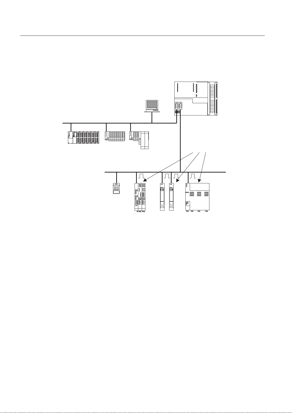
Product Overview
SIEMENS
Interfaces
The Technology CPU has two interfaces:
• One MPI/DP interface, parameterizable as an MPI or DP interface (master or slave).
• one DP (DRIVE) interface for connection of drive systems
MPI/DP interface
03,'3
(70 (76
(76
0,&520$67(5
Figure 2-1 Typical configuration with the Technology CPU
&38[7'3
LVRFKURQRXV
'3GULYH
6,1$0,&60$67(5'5,9(66,02'5,9(
The MPI/DP interface is used to connect additional SIMATIC components, such as PG, OP,
S7 controllers and distributed I/O. Extensive networks can be built up in DP interface mode.
DP(DRIVE) interface
The DP(DRIVE) interface is optimized for the connection of drives. It supports all the major
SIEMENS drive types:
• MICROMASTER 420/430/440 and COMBIMASTER 411
• SIMODRIVE 611 universal
• SIMODRIVE POSMO CD/SI/CA
S7-300 CPU Data: CPU 315T-2 DP
2-2 Manual, 12/2005, A5E00427933-02
• MASTERDRIVES MC/VC
• ET 200M with IM 153-2 (isochronous!) and SM 322 for additional cam output
• ET 200S with IM 151-1 high feature
• SINAMICS S120 (optional with TM15 or TM17 high feature for high-speed cams)
• Analog drive interface ADI4

Product Overview
• Isochronous PROFIBUS encoder "SIMODRIVE sensor isochronous"
The components configured in HW Config are displayed in the "Hardware Catalog" window
in HW Config. To show the screen, select profile "SIMATIC Technology CPU" in HW Config.
To ensure that the profile's selection list is complete, you must have installed the most recent
version of S7-Technology.
The isochronous capability means that even high-speed processes can be controlled with
excellent precision.
Integrated inputs and outputs for integrated technology
The Technology CPU has 4 digital inputs and 8 digital outputs integrated. You use these
inputs and outputs for technology functions, e.g. reference point acquisition (reference cams)
or high-speed output cam switching signals. The inputs and outputs can also be used with
technology functions in the
STEP 7
user program.
Configuring and programming
The Technology CPU is configured and programmed completely in
and later) and optional package
is integrated after installation in
S7-Technology V3.0
STEP 7
).
(the
S7-Technology
STEP 7
(Version 5.3 SP3
optional package
STEP 7
(e.g. to create subnets on the two interfaces MPI/DP and DP(DRIVE)) including the drive
equipment.
You will need optional package
objects", e.g. axes, cams, output cams and probes.
The objects are parameterized in specially provided screens. The technology object data are
stored in data blocks for use by the
S7-Technology
blocks which are used to program the motion control tasks themselves. You call these
standard FBs in your
STEP 7
S7-GRAPH are provided to enable you to create the
control tasks).
Single-tier configuration
The Technology CPU supports only single-tier configurations.
HW Config
languages LAD, CSF and STL and all the required engineering tools, e.g. S7-SCL or
is the tool used to configure all hardware components of the system
S7-Technology
STEP 7
also includes a library containing PLCopen-compliant standard function
STEP 7
user program.
to parameterize the so-called "technology
user program.
STEP 7
user program (incl. motion
S7-300 CPU Data: CPU 315T-2 DP
Manual, 12/2005, A5E00427933-02
2-3

Product Overview
S7-300 CPU Data: CPU 315T-2 DP
2-4 Manual, 12/2005, A5E00427933-02
Operator controls and indicators
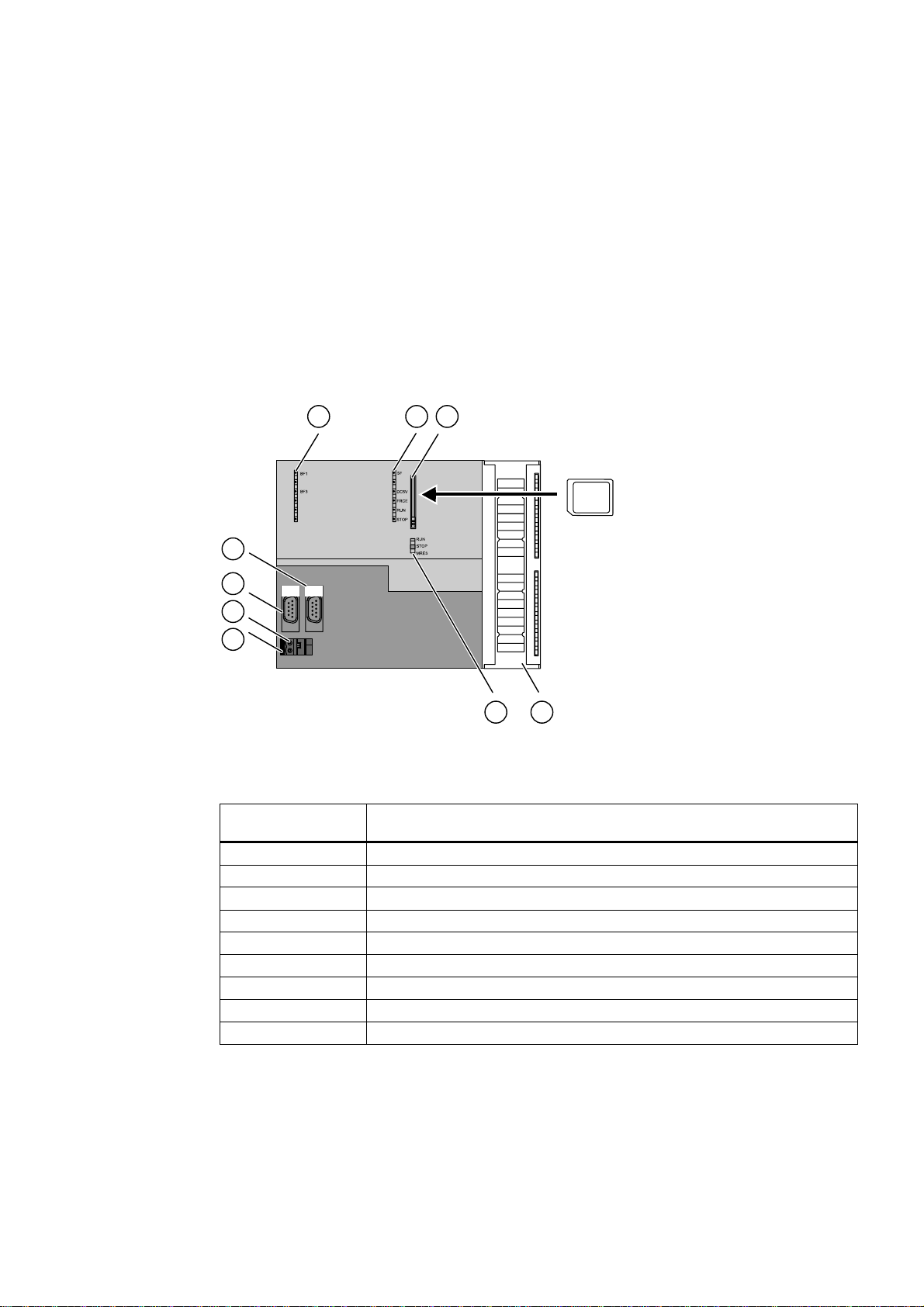
Operator controls and indicators of the CPU
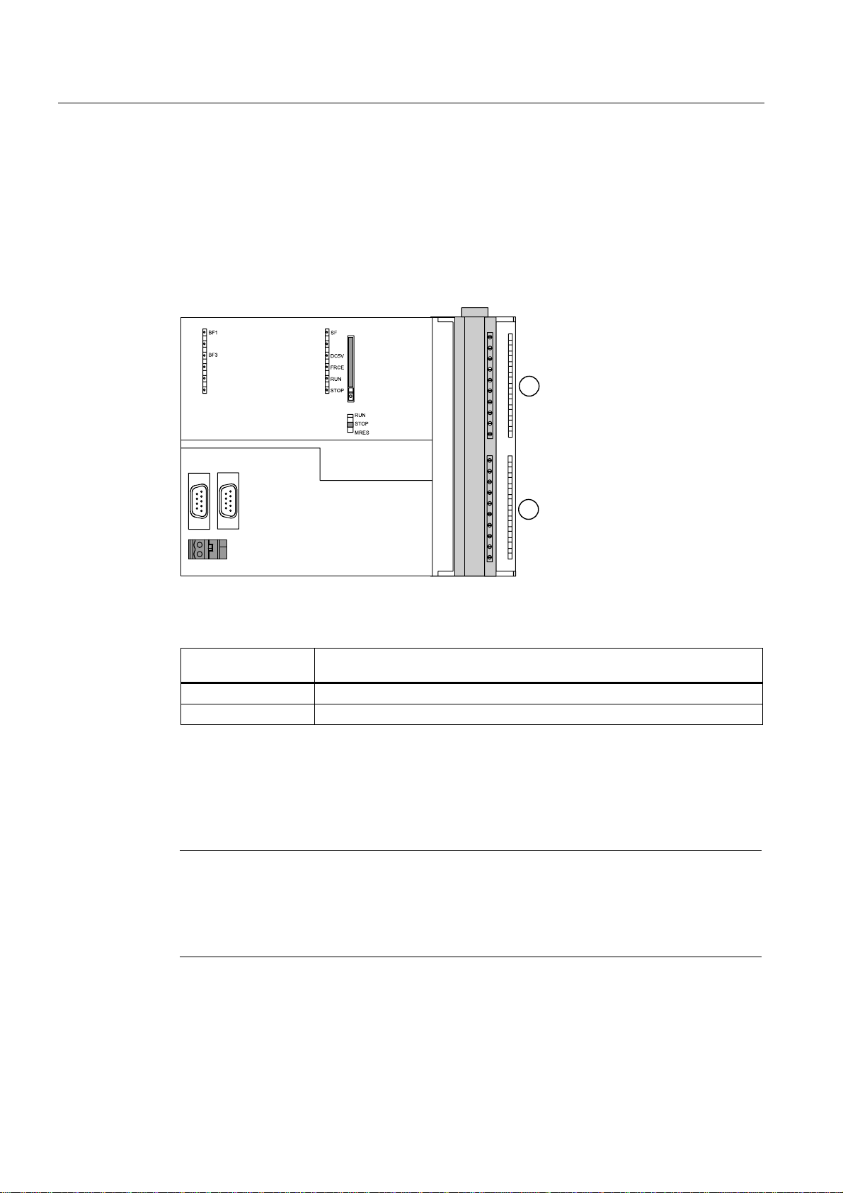
The following diagram shows the operator controls and indicators on the Technology CPU.
Figure 3-1 Operator controls and indicators of the Technology CPU
;
;
;
3
00&
Table 3-1 Operator controls and indicators of the Technology CPU
The number in the
diagram
1 Bus error indicators
2 Status and error displays
3 Slot for the Micro Memory Card (MMC), incl. the ejector
4 Connection of the integrated I/Os
5 Mode selector switch
6 Power supply connection
7 Grounding slide
8 Interface X1 MPI/DP
9 Interface X3 DP(DRIVE)
points to the following element on the Technology CPU
Integrated inputs and outputs for integrated technology
You can use the integrated technology inputs and outputs for technology functions and
configure them using
S7-300 CPU Data: CPU 315T-2 DP
Manual, 12/2005, A5E00427933-02
S7T Config
(included in the optional package
S7-Technology
).
3-1
Operator controls and indicators
The digital outputs are provided for high-speed camming functions. They can be
programmed with technology functions in the STEP 7 user program. Digital inputs can be
used with technology functions such as reference point acquisition (reference cam) as well
as with technology functions in the STEP 7 user program.
You use the integrated inputs and outputs for applications in which rapid technological
processing is of prime importance.
If you wish to evaluate other inputs and outputs in the STEP 7 user program, they can be
interconnected in the usual way by means of supplementary input/output modules.
;
;
;
Figure 3-2 Integrated technology inputs and outputs on the Technology CPU with open front door
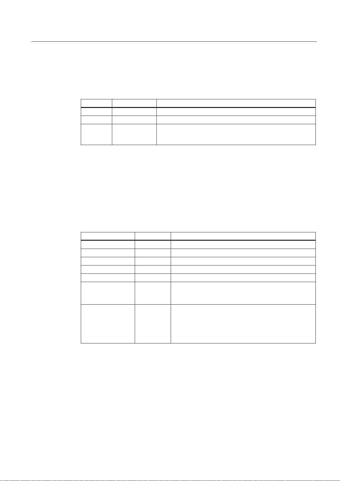
Table 3-2 Integrated technology inputs and outputs on the Technology CPU
The number in the
diagram
1 4 digital inputs
2 8 digital outputs
points to the following integrated I/Os
Slot for the SIMATIC Micro Memory Card (MMC)
A SIMATIC Micro Memory Card (MMC) is used as memory module. The MMC is used as
load memory and as a transportable data medium.
Note
Because the Technology CPU does not have an integrated load memory, you must plug in
an MMC to operate it.
You require an MMC, 4 MB and larger; for an operating system update you require an MMC
with 8 MB.
S7-300 CPU Data: CPU 315T-2 DP
3-2 Manual, 12/2005, A5E00427933-02
Operator controls and indicators
Mode selector switch
The mode selector switch is used to set the current CPU operating mode.
Table 3-3 Switch positions of the mode selector switch
Position Meaning Description
RUN RUN mode The CPU executes the user program.
STOP STOP mode The CPU does not execute a user program.
MRES CPU memory
reset
Mode selector switch position with pushbutton function for CPU
memory reset. A general CPU reset by means of a mode selector
switch requires a specific sequence of operation.
Power supply connection
Each CPU is equipped with a double-pole power supply socket. The connector with screw
terminals is inserted into this socket when the CPU is delivered.
Status and error displays
The CPU is equipped with the following LEDs:
Table 3-4 Status and error displays of the CPU
LED Color Meaning
SF red Hardware or software error
BF1 red Bus errors (MPI/DP)
BF3 red Bus error on DP(DRIVE)
5 VDC green 5V power supply for the CPU and the S7-300 bus
FRCE yellow Active force job
RUN green CPU in RUN
The LED flashes during STARTUP at a rate of 2 Hz, and in
HOLD state at 0.5 Hz.
STOP yellow CPU in STOP, or HOLD, or STARTUP
The LED flashes
• At 0.5 Hz on general reset request
• At 2 Hz during general reset
• At 2 Hz during shutdown (LED RUN lit).
S7-300 CPU Data: CPU 315T-2 DP
Manual, 12/2005, A5E00427933-02
3-3

Operator controls and indicators
Shutdown
What happens during shutdown?
1. The control of the Technology CPU is already in STOP mode during "shutdown". The
outputs of the centralized and distributed I/Os on the MPI/DP are deactivated. The
"STOP" LED flashes at 2 Hz. The "RUN" LED lights up.
2. The integrated inputs/outputs for integrated technology and the distributed I/Os on
DP(DRIVE) are still active during shutdown.
3. The integrated technology of the Technology CPU shuts down the drives on PROFIBUS
DP(DRIVE) in a controlled manner.
4. The integrated technology then also switches to STOP. The integrated inputs/outputs for
integrated technology and the distributed I/Os on DP(DRIVE) are deactivated. The
"STOP" LED lights up.
The maximum duration of shutdown depends on your configuration in S7T Config.
Caution
The distributed I/Os on DP(DRIVE) cannot be controlled from the user program during
"shutdown". The outputs which can be controlled with technology function
"MC_WritePeripherie" retain their last current setting.
Reference
Further information
• about CPU operating modes can be found in the
• about operating the mode selector switch for a general CPU reset can be found in the
installation manual, chapter
• about understanding LED displays in event of faults/trouble shooting can be found in the
installation manual, chapter
• about operating MMCs and the memory concept can be found in chapter
Concept.
Commissioning
Test Functions, Diagnostics and Fault Correction
STEP 7 Online Help
.
.
.
Memory
S7-300 CPU Data: CPU 315T-2 DP
3-4 Manual, 12/2005, A5E00427933-02
Setting up an S7-300 with a Technology CPU
4.1 4.1 Overview
This section
contains the information which differs from the content of installation manual
Programmable Controller, Assembly: CPU 31xc and CPU 31x
information.
4.2 4.2 S7-300 components
Which components do you need to build an S7-300 with Technology CPU?
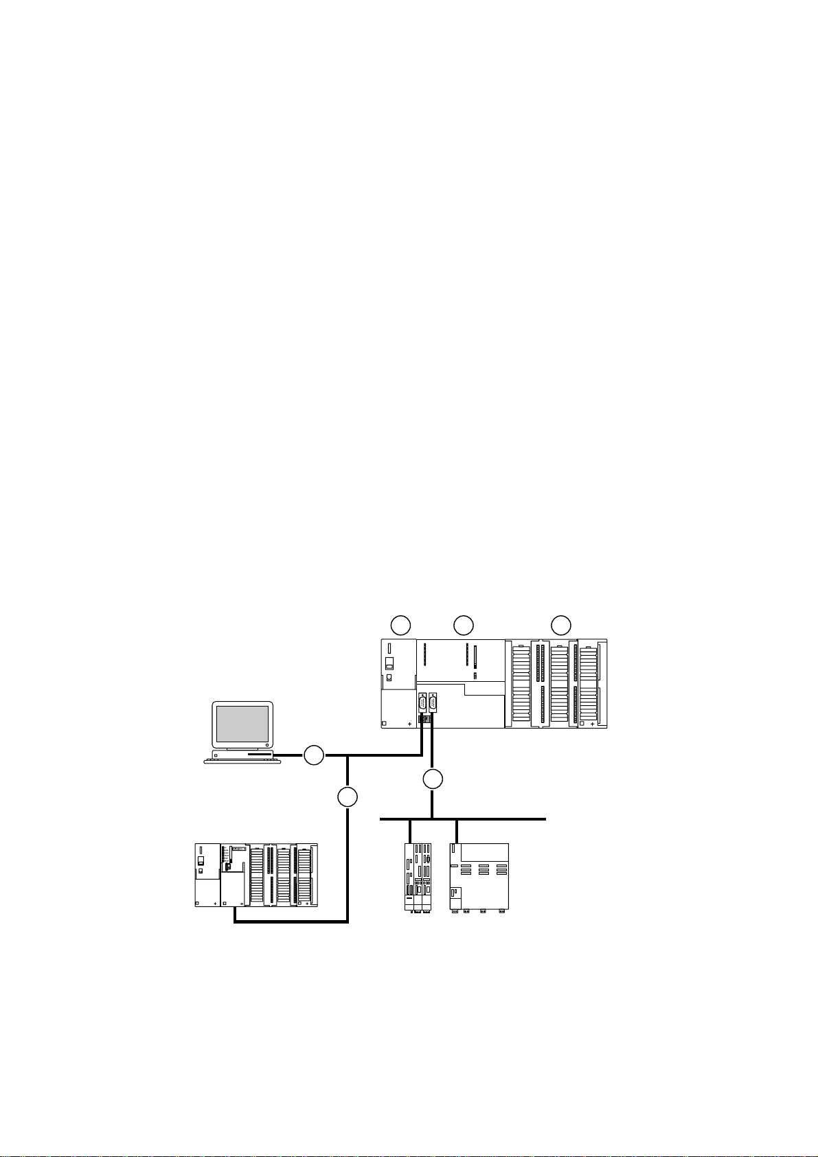
The following diagram shows one possible configuration:
or useful supplementary
4
S7-300
Figure 4-1 S7-300 components
S7-300 CPU Data: CPU 315T-2 DP
Manual, 12/2005, A5E00427933-02
03,'3
'3'5,9(
4-1

Setting up an S7-300 with a Technology CPU
4.3 Configuring
Table 4-1 S7-300 components
The number in the
diagram
(1) Power supply (PS) module
(2) Central processor unit (CPU)
(3) Signal module (SM)
(4) PROFIBUS cable
(5) Cable for connecting a programming device (PG) or for networking with other
You use a programming device (PG) to program the S7300. You connect the PG to the CPU
by means of a PG cable.
Using the PROFIBUS bus cable, you connect the CPU
• to other SIMATIC controls via the MPI/DP interface
• to the drives via the DP(DRIVE) interface.
No PG/OP on DP(DRIVE)
We do not recommend that you connect a PG/OP to DP(DRIVE).
Reason: If you connect a PG/OP to DP(DRIVE), the properties of DP(DRIVE) change (e.g.
isochronism), and the synchronism between drives may be lost as a result. Always therefore
connect a PG/OP to the MPI/DP interface and access the DP(DRIVE) via the "Routing"
function.
points for the following component of an S7-300 system
SIMATIC controls
4.3 4.3 Configuring
Single-tier configuration
The Technology CPU supports only single-tier configurations.
4.4 4.4 Subnets
4.4.1 Expanding and Networking Subnets
Overview: Subnets with the Technology CPU
The Technology CPU provides the following subnets:
• Multi Point Interface (MPI) or PROFIBUS DP
• DP(DRIVE): Optimized for drives
S7-300 CPU Data: CPU 315T-2 DP
4-2 Manual, 12/2005, A5E00427933-02

Setting up an S7-300 with a Technology CPU
4.4 Subnets
Transmission rate
Maximum transmission rates:
• MPI/PROFIBUS DP: 12 Mbaud
We recommend that you set 12 Mbaud for the Technology CPU
• DP(DRIVE): 12 Mbaud
Number of nodes
Note
Before you transfer projects to the Technology CPU via the MPI/DP interface, you should
increase the baud rate to at least 1.5 Mbaud or else the data transmission can take a very
long time (up to 15 minutes at 187.5 kbaud).
Maximum number of nodes per subnet:
Table 4-2 Subnet nodes
Parameters MPI PROFIBUS DP PROFIBUS DP (DRIVE)
Number 127 126 33
Addresses 0 to 126 0 to 125 1 to 125
Comments Default: 32 addresses
Reserved addresses:
• Address 0 for PG
• Address 1 for OP
of which:
1 master (reserved)
1 PG connection
(address 0 reserved)
124 slaves or other
masters
of which:
• 1 master (reserved) and
32 slaves or drives
S7-300 CPU Data: CPU 315T-2 DP
Manual, 12/2005, A5E00427933-02
4-3

Setting up an S7-300 with a Technology CPU
4.4 Subnets
4.4.2 Interfaces
MPI/DP interface
You can reconfigure this interface in STEP 7 as a PROFIBUS DP interface.
The MPI (Multi-Point Interface) represents the CPU interface for PG/OP connections, or for
communication on an MPI subnet.
The PROFIBUS DP interface is mainly used to connect distributed I/O. PROFIBUS DP
allows you to create large subnets, for example.
Interfaces
Table 4-3 Possible operating modes of interfaces on the Technology CPU
MPI/DP interface (X1) DP(DRIVE) interface (X3)
• MPI
• DP master
• DP slave
• DP master for DP(DRIVE)
Which devices can you connect to which interface?
Table 4-4 Connectable devices
MPI PROFIBUS DP DP (drive)
• PG/PC
• OP/TD
• S7-300/400 with
MPI interface
• S7-200
(with 19.2 kbaud only)
• PG/PC
• OP/TD
• DP slaves
• DP master
• Actuators/sensors
• S7-300/400 with
PROFIBUS
DP interface
• MICROMASTER 420/430/440 and
COMBIMASTER 411
• SIMODRIVE 611 universal
• SIMODRIVE POSMO CD/SI/CA
• MASTERDRIVES MC/VC
• ET 200M with IM 153-2 (isochronous!)
• ET 200S with IM 151-1
• SINAMICS S120 (optional with TM15
or TM17 high feature for high-speed
cams)
• SIMODRIVE sensor isochronous
• Analog drive interface ADI4
Tip: You will find a list of connectable
devices in STEP 7 under the "SIMATIC
Technology CPU" profile in the hardware
catalog.
S7-300 CPU Data: CPU 315T-2 DP
4-4 Manual, 12/2005, A5E00427933-02
Setting up an S7-300 with a Technology CPU
4.5 Addressing
4.5 4.5 Addressing
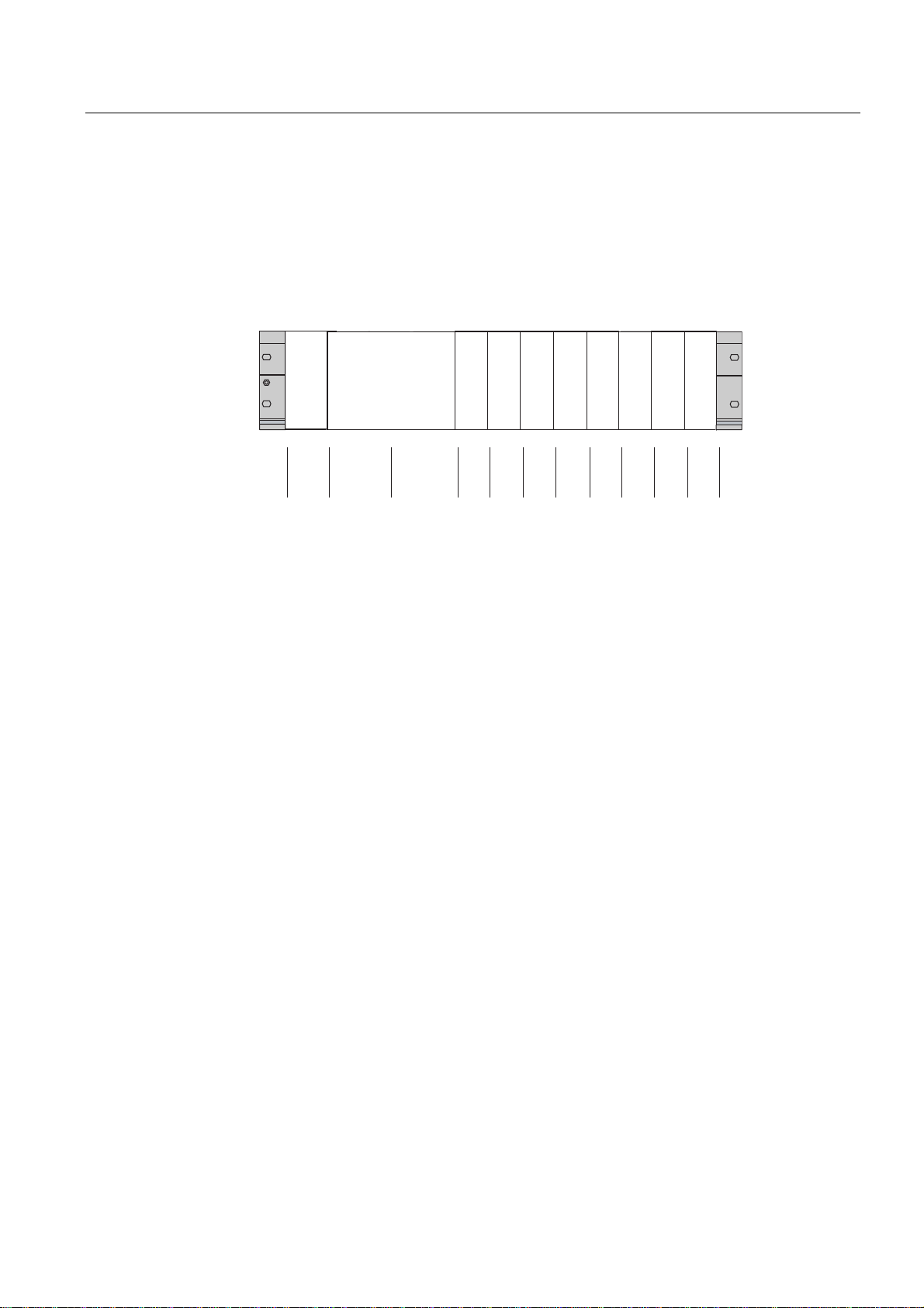
Slots of the S7-300 and associated module start addresses
The Technology CPU is assigned to two slot numbers: 2 and 3.
The input and output addresses for I/O modules begin at the same module start address.
0RGXOHUDFN
&5
&3836
60 60 60
60 60
60
60
60
6ORWQXPEHU
0'LQLWLDODGGUHVVGLJLWDO
0'LQLWLDODGGUHVVDQDORJ
3/&VHFWLRQ
7HFKQRORJ\VHFWLRQ
Figure 4-2 Slots of the S7-300 with Technology CPU and associated module start addresses
Integrated inputs and outputs for integrated technology
The Technology CPU has 4 integrated digital iputs and 8 integrated digital outputs for
integrated technology. You use these integrated inputs and outputs for technology functions,
e.g. reference point acquisition (reference cams) or high-speed output cam switching
signals.
The integrated inputs and outputs can also be used with technology function in the STEP 7
user program.
You use the integrated inputs and outputs for applications in which rapid technological
processing is of prime importance.
DP address areas
The CPU 315T-2 DP has the following address areas:
• For inputs and outputs respectively: 2048 bytes
• Of which in the process image, for inputs and outputs respectively: Bytes 0 to 127
DP (DRIVE) address areas
The CPU 315T-2 DP has the following DP(DRIVE) address areas:
• For inputs and outputs respectively: 1024 bytes
• Of which in the I/O image, for inputs and outputs respectively: Bytes 0 to 63
S7-300 CPU Data: CPU 315T-2 DP
Manual, 12/2005, A5E00427933-02
4-5

Setting up an S7-300 with a Technology CPU
4.6 Commissioning
4.6 4.6 Commissioning
Conditions
If you wish to utilize the full scope of CPU functions, you will require
• STEP 7 as of V 5.3 + SP 3 and option package
• S7-300 is installed
• S7-300 is wired
• For a networked S7-300:
– MPI/PROFIBUS addresses are set
– Terminating resistors on the segments are enabled
4.7 4.7 Operating system
Technology CPU operating system
To meet the requirements of the integrated technology, technology functions have been
added to the standard CPU operating system to obtain the technology operating system.
The technology operating system is included in the project and the configuration. In other
words, if you load a project created with S7-Technology to the Technology CPU, the
technology operating system is automatically transferred at the same time.
Updating the operating system
You can order the latest operating system versions from your Siemens contact or download
it from the Internet at (Siemens Homepage; Industrial Automation, Customer Support).
S7-Technology V3.0
4.8 4.8 Status and error displays of the Technology CPU
Status and error displays of the Technology CPU
Table 4-5 Status and error displays of the Technology CPU
LED Meaning
SF 5 VDC FRCE RUN STOP
Off Off Off Off Off CPU power supply missing.
Remedy:
Check whether the power supply module is connected to mains and
switched on.
Check whether the CPU is connected to the power supply and switched on.
S7-300 CPU Data: CPU 315T-2 DP
4-6 Manual, 12/2005, A5E00427933-02

Setting up an S7-300 with a Technology CPU
4.8 Status and error displays of the Technology CPU
LED Meaning
SF 5 VDC FRCE RUN STOP
Off On
On On X Off On The CPU is in STOP mode as a result of error.
X On X Off Flashes
X On X Off Flashes
X On X Flashes
X On X Flashes
On On X X X Hardware or software error
X X On X X You enabled the Force function
X X X On Flashes
X X X Flashes
Flashes Flashes Flashes Flashes Flashes Internal errors in Technology CPU.
X (see the
description)
Off On The CPU is in STOP mode.
Remedy: Start the CPU.
Remedy: refer to the tables below, evaluation of the SF LED
The CPU requests memory reset.
(0.5 Hz)
The CPU executes memory reset.
(2 Hz)
On The CPU is in startup mode.
(2 Hz)
On The CPU was halted by a programmed break point.
(0.5 Hz)
(0.5 Hz)
(2 Hz)
Flashes
(2 Hz)
For details, refer to the Programming Manual
STEP 7
Remedy: refer to the tables below, evaluation of the SF LED
For details refer to the Programming Manual
STEP 7
STOP/shutdown
What happens during shutdown?
The control of the Technology CPU is already in STOP mode during
"shutdown". The outputs of the centralized and distributed I/Os are
deactivated.
The integrated inputs/outputs for integrated technology and the
ET 200M on the DP(DRIVE) are still active during shutdown.
The integrated technology of the Technology CPU shuts down the
drives on PROFIBUS DP(DRIVE) in a controlled manner.
The integrated technology of the CPU then also goes into STOP.
The integrated inputs/outputs for integrated technology and the
ET 200M on the DP(DRIVE) are deactivated.
The maximum duration of shutdown depends on your configuration
in S7TConfig.
HOLD/shutdown
Contact your local SIEMENS partner.
.
.
Programming with
Programming with
S7-300 CPU Data: CPU 315T-2 DP
Manual, 12/2005, A5E00427933-02
4-7

Setting up an S7-300 with a Technology CPU
4.8 Status and error displays of the Technology CPU
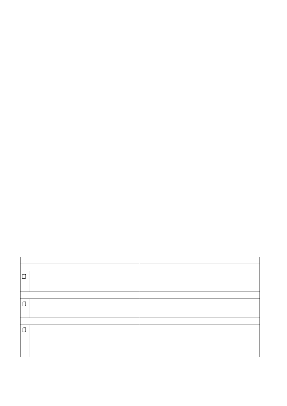
Status and error displays for DP or DP(DRIVE)
Table 4-6 LEDs BF1 and BF3
LED Meaning
BF1 BF3
On/ flashes X Error on the PROFIBUS DP interface of the Technology CPU.
Remedy: See table LED BF1 illuminated
X On/ flashes Error on the DP(DRIVE) interface
Remedy: See table
Description of status X:
The LED can assume the On or Off state. This status, however, is irrelevant for the current
CPU function. For example, the states Force On or Off do not influence the CPU STOP
status
Table 4-7 LED BF1 illuminated
Possible Errors CPU reaction Possible Remedies
• Bus fault (physical fault)
• DP interface error
• Different transmission rates in
multiple DP master mode.
• If the DP slave / master interface is
active: Short-circuit on the bus.
• With passive DP slave interface:
transmission rate search, i.e. there
are no other active nodes on the
bus (a master, for example)
Call of OB 86 (when CPU is in RUN
mode). CPU switches to STOP if OB
86 is not loaded.
LED BF1 flashing
• Check the bus cable for short-circuit
or breaks.
• Evaluate the diagnostics.
Reconfigure or correct the
configuration.
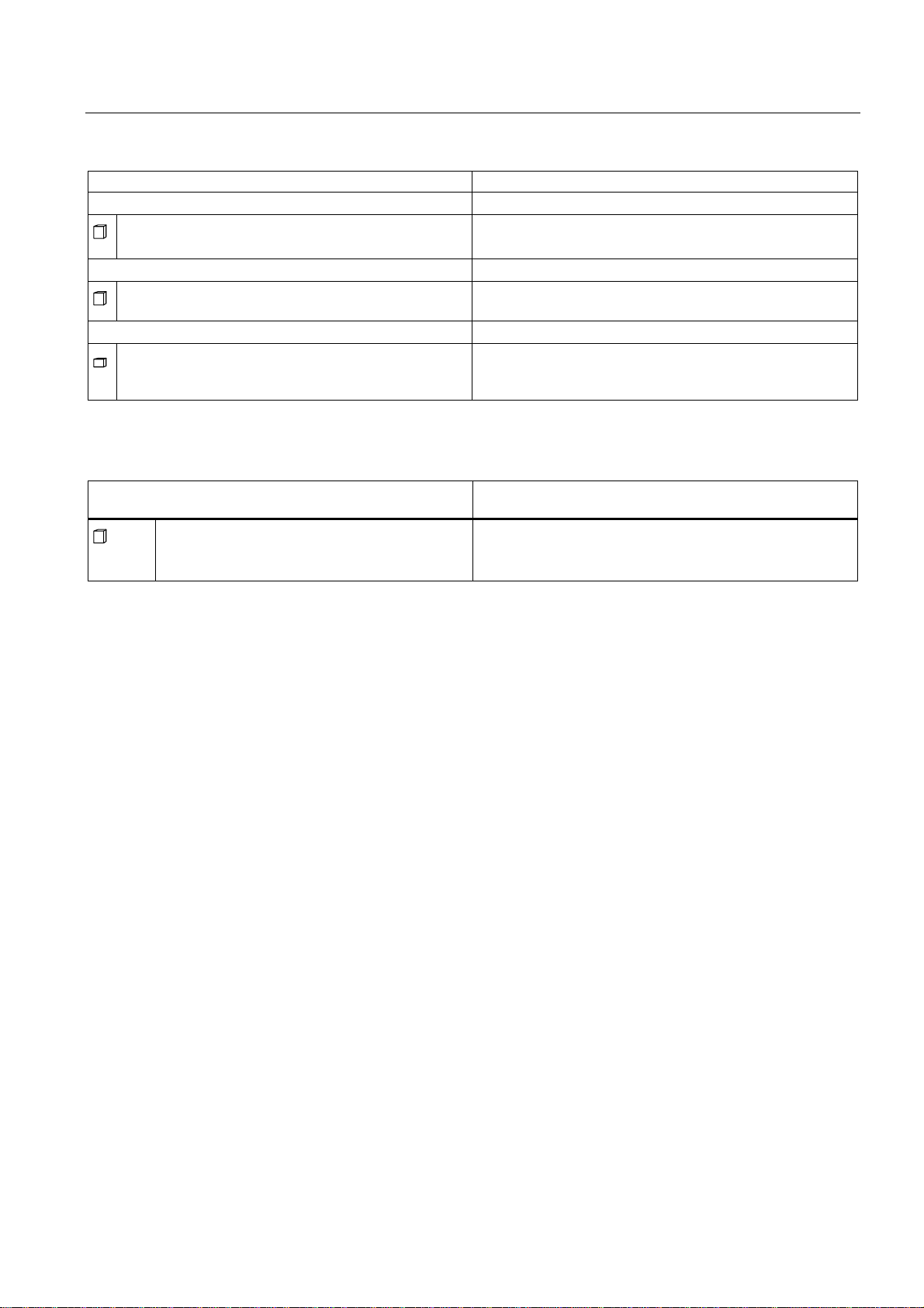
Table 4-8 ED BF1 flashes
Possible Errors CPU reaction Possible Remedies
The CPU is DP master / active slave:
• Failure of a connected station
• At least one of the configured
slaves cannot be accessed.
• Incorrect configuration
The CPU is a DP slave
The CPU parameters are incorrectly
set. Possible causes:
• The response monitoring period has
elapsed.
• PROFIBUS DP communication is
down.
• Wrong PROFIBUS address.
• Incorrect configuration
Call of OB 86 (when CPU is in RUN
mode). CPU switches to STOP if OB
86 is not loaded.
Call of OB 86
(if CPU is in RUN mode).
CPU switches to STOP if OB 86 is not
loaded.
Verify that the bus cable is connected
to the CPU, or that the bus is not
interrupted.
Wait until the CPU has completed its
startup. If the LED does not stop
flashing, check the DP slaves or
analyze the diagnostic data of the DP
slaves.
• Check the CPU.
• Verify that the bus connector is
properly seated.
• Check whether the bus cable to the
DP master has been disconnected.
• Check the configuration and
parameter assignment.
S7-300 CPU Data: CPU 315T-2 DP
4-8 Manual, 12/2005, A5E00427933-02

Setting up an S7-300 with a Technology CPU
4.8 Status and error displays of the Technology CPU
Table 4-9 LED BF3 illuminated
Possible Errors CPU reaction Possible Remedies
• Bus fault (physical fault)
• DP interface error
Error message in the technology DB
configured by you.
Check for short-circuit or interruption in
the bus cable.
Table 4-10 LED BF3 flashes
Possible Errors CPU reaction Possible Remedies
• Failure of a connected station
• At least one of the configured
slaves cannot be accessed.
• Incorrect configuration
Error message in the technology DB
configured by you.
Verify that the bus cable is connected
to the CPU, or that the bus is not
interrupted.
Wait until the CPU has completed its
startup. If the LED does not stop
flashing, check the DP slaves or
analyze the diagnostic data of the DP
slaves.
S7-300 CPU Data: CPU 315T-2 DP
Manual, 12/2005, A5E00427933-02
4-9

Setting up an S7-300 with a Technology CPU
4.8 Status and error displays of the Technology CPU
S7-300 CPU Data: CPU 315T-2 DP
4-10 Manual, 12/2005, A5E00427933-02
Communication with the S7-300
5.1 5.1 Interfaces
5.1.1 Overview
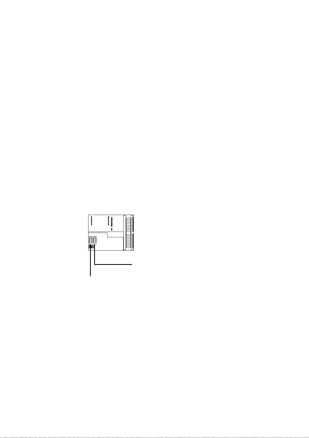
Overview
The Technology CPU has two interfaces:
• MPI/DP interface (X1)
• PROFIBUS DP(DRIVE) interface (X3)
&38[7'3
5
03,'3
Figure 5-1 Technology CPU interfaces
S7-300 CPU Data: CPU 315T-2 DP
Manual, 12/2005, A5E00427933-02
'3'5,9(
5-1

Communication with the S7-300
5.1 Interfaces
5.1.2 MPI/DP interface (X1)
Availability
The Technology CPU features an MPI/DP interface (X1). A CPU with MPI/DP interface is
supplied with default MPI parameter settings. Depending on your requirements, you may
need to reconfigure the interface as a DP interface in STEP 7.
MPI properties
The MPI (Multi-Point Interface) represents the CPU interface for PG/OP connections, or for
communication on an MPI subnet.
The typical (default) transmission rate of all CPUs is 187.5 kbaud. You can also set 19.2
kbps for communication with an S7-200. You can set baud rates of up to 12 Mbaud.
The CPU automatically broadcasts its bus configuration via the MPI interface (the
transmission rate, for example). A PG, for example, can thus receive the correct parameters
and automatically connect to a MPI subnet.
Note
You may only connect PGs to an MPI subnet which is in RUN.
Other stations (for example, OP, TD, ...) should not be connected to the MPI subnet while
the system is in RUN. Otherwise, transferred data might be corrupted as a result
interference, or global data packages may be lost.
Note
Before you transfer data to the CPU via the MPI interface, you should increase the baud rate
to 1.5 Mbaud or else the data transmission can take a very long time (up to 15 minutes at
187.5 kbaud)!
Operating modes of the MPI/DP interface
Operating modes for MPI/DP interface (X1):
• MPI
• DP master
• DP slave
• I slave
S7-300 CPU Data: CPU 315T-2 DP
5-2 Manual, 12/2005, A5E00427933-02
 Loading...