

Siemens SIMATIC S7-300 Series, CPU 314 IFM, CPU 315, CPU 315-2 DP, CPU 316-2 DP Reference Manual
...
DATASHEET
6ES7314-5AE03-0AB0
SIEMENS
OTHER SYMBOLS:
RGB ELEKTRONIKA AGACIAK CIACIEK
SPÓŁKA JAWNA
Jana Dlugosza 2-6 Street
51-162 Wrocław
Poland
biuro@rgbelektronika.pl
+48 71 325 15 05
www.rgbautomatyka.pl
www.rgbelektronika.pl
www.rgbelektronika.pl
www.rgbautomatyka.pl
YOUR
PARTNER IN
MAINTENANCE
Repair this product with RGB ELEKTRONIKA
LINEAR
ENCODERS
ENCODERS
SERVO AMPLIFIERS
CNC
MACHINES
OUR SERVICES
PLC
SYSTEMS
CNC
CONTROLS
ORDER A DIAGNOSIS
INDUSTRIAL
COMPUTERS
POWER
SUPPLIERS
∠
MOTORS
SERVO
DRIVERS
At our premises in Wrocław, we have a fully equipped servicing facility. Here we perform all the repair
works and test each later sold unit. Our trained employees, equipped with a wide variety of tools and
having several testing stands at their disposal, are a guarantee of the highest quality service.
Buy this product at RGB AUTOMATYKA
OPERATOR
PANELS
BUY
∠
Preface, Contents
SIMATIC
PLC S7-300,
CPU Specifications CPU 312 IFM
to CPU 318-2 DP
Reference Manual
CPUs
CPU 31x-2 as DP Master/DP
Slave and Direct Communication
Cycle and Reaction times
CPU Function, depending on
CPU and STEP 7 Version
Tips and Tricks
Appendix
Standards, Certificates and
Approvals
Dimensioned Drawings
List of Abbreviations
1
2
3
4
5
A
B
C
This manual is part of the documentation
package with the order number
6ES7398-8FA10-8BA0
Edition 10/2001
A5E00111190-01
This documentation can no longer be ordered under
the given number!
Glossary, Index
Safety Guidelines
This manual contains notices intended to ensure personal safety, as well as to protect the products and
connected equipment against damage. These notices are highlighted by the symbols shown below and
graded according to severity by the following texts:
Danger
!
indicates that death, severe personal injury or substantial property damage will result if proper precautions
are not taken.
Warning
!
indicates that death, severe personal injury or substantial property damage can result if proper
precautions are not taken.
Caution
!
indicates that minor personal injury can result if proper precautions are not taken.
Caution
indicates that property damage can result if proper precautions are not taken.
Notice
draws your attention to particularly important information on the product, handling the product, or to a
particular part of the documentation.
Qualified Personnel
Only qualified personnel should be allowed to install and work on this equipment. Qualified persons are
defined as persons who are authorized to commission, to ground and to tag circuits, equipment, and
systems in accordance with established safety practices and standards.
Correct Usage
Note the following:
Warning
!
Trademarks
The reproduction, transmission or use of this document or its
contents is not permitted without express written authority.
Offenders will be liable for damages. All rights, including rights
created by patent grant or registration of a utility model or
design, are reserved.
Siemens AG
Bereich Automatisierungs- und Antriebstechnik
Geschaeftsgebiet Industrie-Automatisierungssysteme
Postfach 4848, D- 90327 Nuernberg
Index-2
Siemens Aktiengesellschaft A5E00111190
This device and its components may only be used for the applications described in the catalog or the
technical description, and only in connection with devices or components from other manufacturers which
have been approved or recommended by Siemens.
This product can only function correctly and safely if it is transported, stored, set up, and installed
correctly, and operated and maintained as recommended.
SIMATIC, SIMA TIC HMI and SIMATIC NET are registered trademarks of SIEMENS AG.
Third parties using for their own purposes any other names in this document which refer to trademarks
might infringe upon the rights of the trademark owners.
Disclaim of LiabilityCopyright W Siemens AG 2001 All rights reserved
We have checked the contents of this manual for agreement
with the hardware and software described. Since deviations
cannot be precluded entirely, we cannot guarantee full
agreement. However, the data in this manual are reviewed
regularly and any necessary corrections included in
subsequent editions. Suggestions for improvement are
welcomed.
Siemens AG 2001
Technical data subject to change.
PLC S7-300, CPU Specifications CPU 312 IFM to CPU 318-2 DP
A5E00111190-01
Preface
Purpose of the Manual
This manual gives you a brief overview of 312 IFM to 318-2 CPUS in an S7-300.
You can look up information on how to operate the system, its functions and
technical data of the CPUs.
Essential know-how
General knowledge of automation technology is required for comprehension of this
Manual. You should also be acquainted with basic STEP 7 software as described
in your Programming with STEP 7 V 5.1 Manual.
PLC S7-300, CPU Specifications CPU 312 IFM to CPU 318-2 DP
A5E00111190-01
iii
Preface
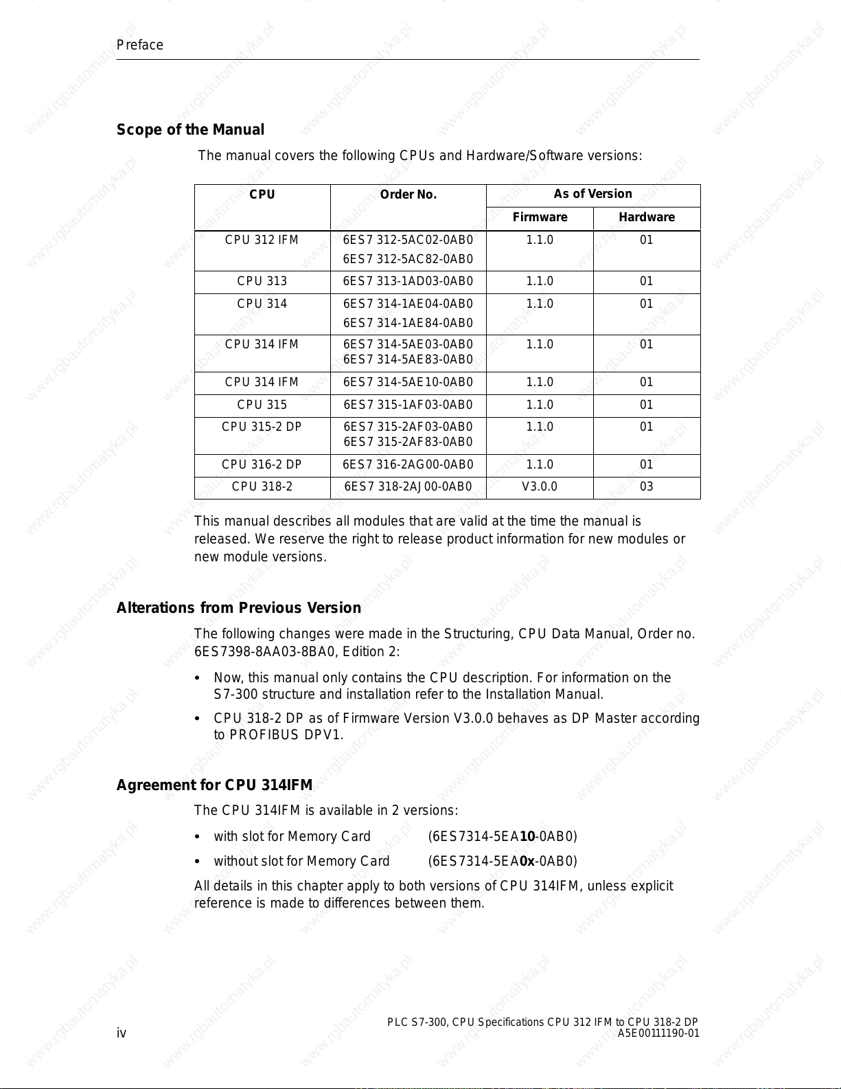
Scope of the Manual
The manual covers the following CPUs and Hardware/Software versions:
CPU Order No.
CPU 312 IFM 6ES7 312-5AC02-0AB0
6ES7 312-5AC82-0AB0
CPU 313 6ES7 313-1AD03-0AB0 1.1.0 01
CPU 314 6ES7 314-1AE04-0AB0
6ES7 314-1AE84-0AB0
CPU 314 IFM 6ES7 314-5AE03-0AB0
6ES7 314-5AE83-0AB0
CPU 314 IFM 6ES7 314-5AE10-0AB0 1.1.0 01
CPU 315 6ES7 315-1AF03-0AB0 1.1.0 01
CPU 315-2 DP 6ES7 315-2AF03-0AB0
6ES7 315-2AF83-0AB0
CPU 316-2 DP 6ES7 316-2AG00-0AB0 1.1.0 01
CPU 318-2 6ES7 318-2AJ00-0AB0 V3.0.0 03
As of Version
Firmware Hardware
1.1.0 01
1.1.0 01
1.1.0 01
1.1.0 01
This manual describes all modules that are valid at the time the manual is
released. We reserve the right to release product information for new modules or
new module versions.
Alterations from Previous Version
The following changes were made in the Structuring, CPU Data Manual, Order no.
6ES7398-8AA03-8BA0, Edition 2:
Now, this manual only contains the CPU description. For information on the
S7-300 structure and installation refer to the Installation Manual.
CPU 318-2 DP as of Firmware Version V3.0.0 behaves as DP Master according
to PROFIBUS DPV1.
Agreement for CPU 314IFM
The CPU 314IFM is available in 2 versions:
with slot for Memory Card (6ES7314-5EA10-0AB0)
without slot for Memory Card (6ES7314-5EA0x-0AB0)
All details in this chapter apply to both versions of CPU 314IFM, unless explicit
reference is made to differences between them.
iv
PLC S7-300, CPU Specifications CPU 312 IFM to CPU 318-2 DP
A5E00111190-01
Approbation, Standards and Approvals
The SIMATIC S7-300 series conforms to:
Requirements and criteria to IEC 61131, Part 2
CE labeling
– EC Guideline 73/23/EEC on Low Voltages
– EC Guideline 89/336/EEC on electromagnetic compatibility (EMC)
Canadian Standards Association: CSA C22.2 Number 142, tested (Process
Control Equipment)
Underwriters Laboratories, Inc.: UL 508 registered (Industrial Control
Equipment)
Underwriters Laboratories, Inc.: UL 508 (Industrial Control Equipment)
Factory Mutual Research: Approval Standard Class Number 3611
C-Tick Australia
Preface
PLC S7-300, CPU Specifications CPU 312 IFM to CPU 318-2 DP
A5E00111190-01
v
Preface
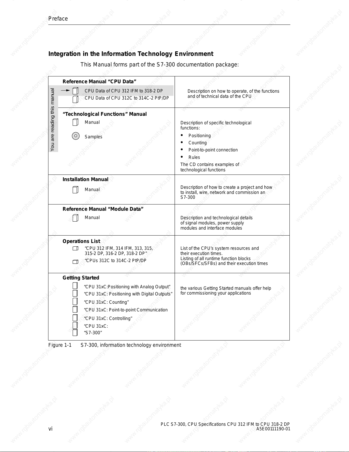
Integration in the Information Technology Environment
This Manual forms part of the S7-300 documentation package:
Reference Manual “CPU Data”
CPU Data of CPU 312 IFM to 318-2 DP
CPU Data of CPU 312C to 314C-2 PtP/DP
“Technological Functions” Manual
Manual
Samples
Description on how to operate, of the functions
and of technical data of the CPU
Description of specific technological
functions:
Positioning
Counting
You are reading this manual
Point-to-point connection
Rules
The CD contains examples of
technological functions
Installation Manual
Manual
Description of how to create a project and how
to install, wire, network and commission an
S7-300
Reference Manual “Module Data”
Manual
Operations List
“CPU 312 IFM, 314 IFM, 313, 315,
315-2 DP, 316-2 DP, 318-2 DP”
“CPUs 312C to 314C-2 PtP/DP
Getting Started
“CPU 31xC:Positioning with Analog Output”
“CPU 31xC: Positioning with Digital Outputs”
“CPU 31xC: Counting”
“CPU 31xC: Point-to-point Communication
“CPU 31xC: Controlling”
“CPU 31xC:
“S7-300”
Figure 1-1 S7-300, information technology environment
Description and technological details
of signal modules, power supply
modules and interface modules
List of the CPU’s system resources and
their execution times.
Listing of all runtime function blocks
(OBs/SFCs/SFBs) and their execution times
the various Getting Started manuals offer help
for commissioning your applications
vi
PLC S7-300, CPU Specifications CPU 312 IFM to CPU 318-2 DP
A5E00111190-01
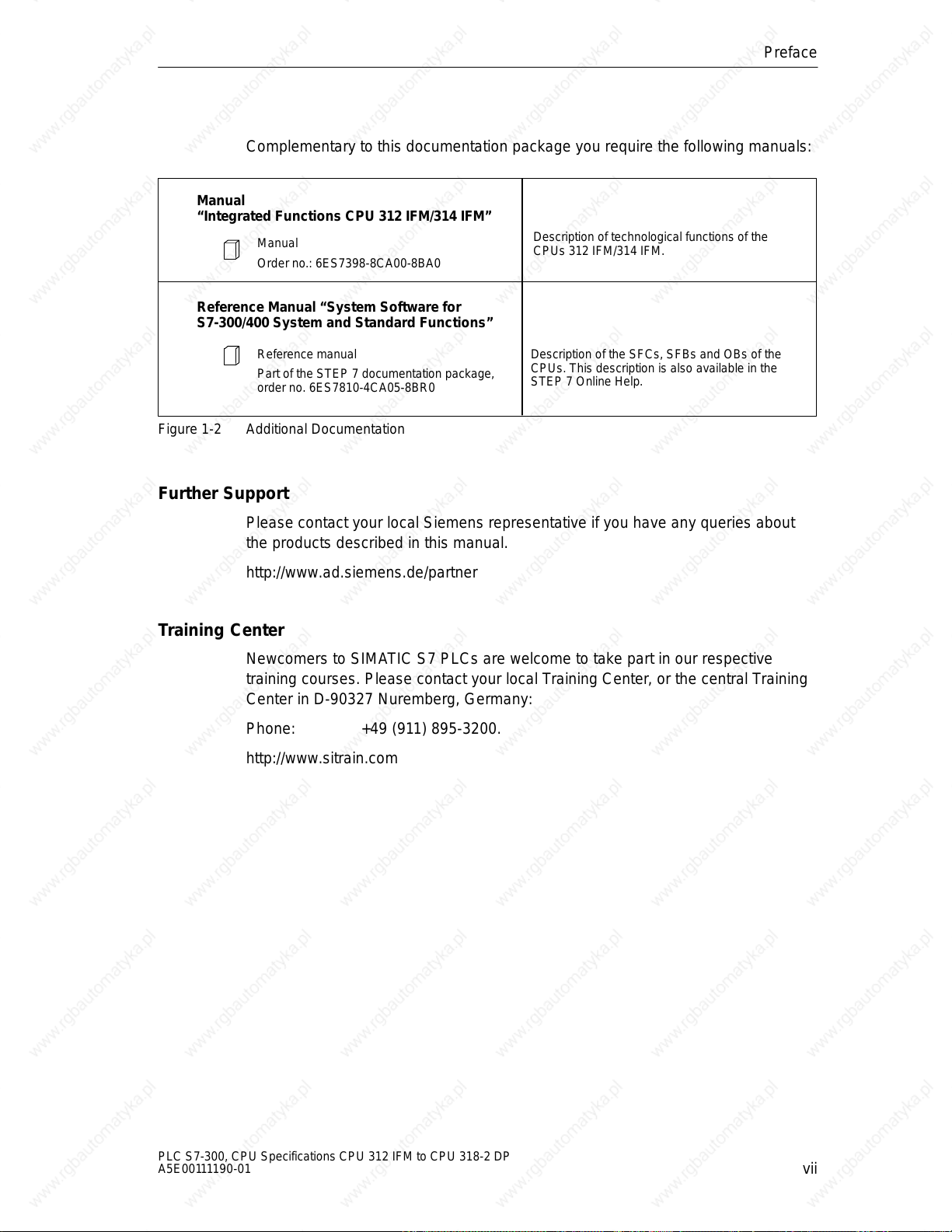
Complementary to this documentation package you require the following manuals:
Manual
“Integrated Functions CPU 312 IFM/314 IFM”
Manual
Order no.: 6ES7398-8CA00-8BA0
Reference Manual “System Software for
S7-300/400 System and Standard Functions”
Preface
Description of technological functions of the
CPUs 312 IFM/314 IFM.
Reference manual
Part of the STEP 7 documentation package,
order no. 6ES7810-4CA05-8BR0
Figure 1-2 Additional Documentation
Further Support
Please contact your local Siemens representative if you have any queries about
the products described in this manual.
http://www.ad.siemens.de/partner
Training Center
Newcomers to SIMATIC S7 PLCs are welcome to take part in our respective
training courses. Please contact your local Training Center, or the central Training
Center in D-90327 Nuremberg, Germany:
Phone: +49 (911) 895-3200.
http://www.sitrain.com
Description of the SFCs, SFBs and OBs of the
CPUs. This description is also available in the
STEP 7 Online Help.
PLC S7-300, CPU Specifications CPU 312 IFM to CPU 318-2 DP
A5E00111190-01
vii
Preface
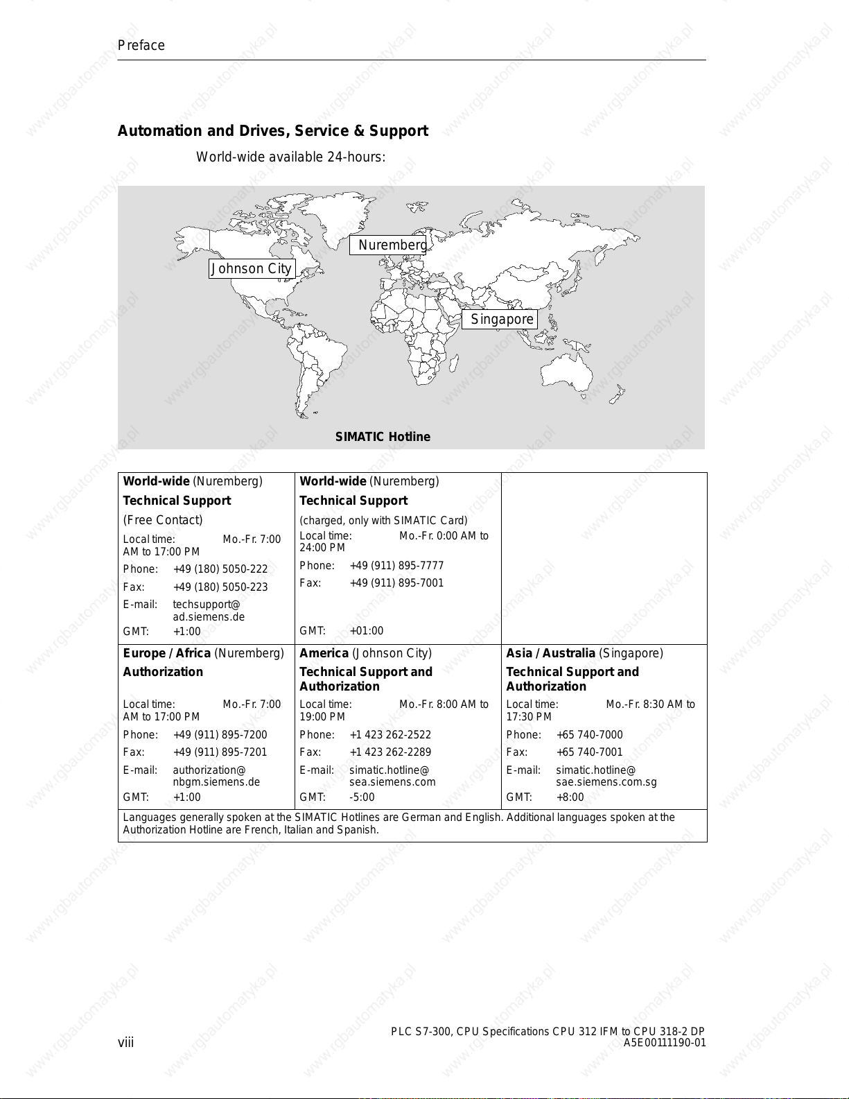
Automation and Drives, Service & Support
World-wide available 24-hours:
Nuremberg
Johnson City
SIMATIC Hotline
Singapore
World-wide (Nuremberg)
T echnical Support
(Free Contact)
Local time: Mo.-Fr. 7:00
AM to 17:00 PM
Phone: +49 (180) 5050-222
Fax: +49 (180) 5050-223
E-mail: techsupport@
ad.siemens.de
GMT: +1:00
Europe / Africa (Nuremberg)
Authorization
Local time: Mo.-Fr. 7:00
AM to 17:00 PM
Phone: +49 (911) 895-7200
Fax: +49 (911) 895-7201
E-mail: authorization@
nbgm.siemens.de
GMT: +1:00
Languages generally spoken at the SIMATIC Hotlines are German and English. Additional languages spoken at the
Authorization Hotline are French, Italian and Spanish.
World-wide (Nuremberg)
T echnical Support
(charged, only with SIMATIC Card)
Local time: Mo.-Fr. 0:00 AM to
24:00 PM
Phone: +49 (911) 895-7777
Fax: +49 (911) 895-7001
GMT: +01:00
America (Johnson City)
Technical Support and
Authorization
Local time: Mo.-Fr. 8:00 AM to
19:00 PM
Phone: +1 423 262-2522
Fax: +1 423 262-2289
E-mail: simatic.hotline@
sea.siemens.com
GMT: -5:00
Asia / Australia (Singapore)
Technical Support and
Authorization
Local time: Mo.-Fr. 8:30 AM to
17:30 PM
Phone: +65 740-7000
Fax: +65 740-7001
E-mail: simatic.hotline@
sae.siemens.com.sg
GMT: +8:00
viii
PLC S7-300, CPU Specifications CPU 312 IFM to CPU 318-2 DP
A5E00111190-01
SIMATIC Documentation on the Internet
Documentation is available free of charge on the Internet under:
http://www.ad.siemens.de/support
Please use the Knowledge Manager offered at these locations for quick location of
your required documentation. Our Internet Forum offers a “Documentation”
conferencing room for your questions and solution proposals.
http://www.ad.siemens.de/support
Service & Support on the Internet
As a supplement to our provided documentation we offer our complete know-how
base on the Internet.
http://www.ad.siemens.de/support
There you will find:
Up-to-date product information (News), FAQs (Frequently Asked Questions),
Downloads, Tips and Tricks.
Preface
Our Newsletter always offers you the most up-to-date information on your
products.
The Knowledge Manager finds the right documents for you.
Users and specialists across the globe share their experiences in our Forum.
Your local service partner for Automation & Drives is found in our Service
Partner Database.
Information relating to on–site Service, repairs, spare parts and lots more is
available to you under the topic “Service”.
PLC S7-300, CPU Specifications CPU 312 IFM to CPU 318-2 DP
A5E00111190-01
ix

Preface
x
PLC S7-300, CPU Specifications CPU 312 IFM to CPU 318-2 DP
A5E00111190-01
Contents
1 CPUs
1.1 Control and Display Elements 1-2 . . . . . . . . . . . . . . . . . . . . . . . . . . . . . . . . . . . . .
1.1.1 Status and Fault Displays 1-3 . . . . . . . . . . . . . . . . . . . . . . . . . . . . . . . . . . . . . . . .
1.1.2 Mode Selector Switch 1-4 . . . . . . . . . . . . . . . . . . . . . . . . . . . . . . . . . . . . . . . . . . . .
1.1.3 Backup battery/accumulator 1-5 . . . . . . . . . . . . . . . . . . . . . . . . . . . . . . . . . . . . . .
1.1.4 Memory card 1-6 . . . . . . . . . . . . . . . . . . . . . . . . . . . . . . . . . . . . . . . . . . . . . . . . . . .
1.1.5 MPI and PROFIBUS-DP Interface 1-7 . . . . . . . . . . . . . . . . . . . . . . . . . . . . . . . . .
1.1.6 Clock and Runtime Meter 1-10 . . . . . . . . . . . . . . . . . . . . . . . . . . . . . . . . . . . . . . . . .
1.2 Communication Options of the CPU 1-11 . . . . . . . . . . . . . . . . . . . . . . . . . . . . . . .
1.3 Test Functions and Diagnostics 1-19 . . . . . . . . . . . . . . . . . . . . . . . . . . . . . . . . . . .
1.3.1 Testing Functions 1-19 . . . . . . . . . . . . . . . . . . . . . . . . . . . . . . . . . . . . . . . . . . . . . . .
1.3.2 Diagnostics with LED Display 1-22 . . . . . . . . . . . . . . . . . . . . . . . . . . . . . . . . . . . . .
1.3.3 Diagnostics with STEP 7 1-22 . . . . . . . . . . . . . . . . . . . . . . . . . . . . . . . . . . . . . . . . .
1.4 CPUs - Technical Specifications 1-24 . . . . . . . . . . . . . . . . . . . . . . . . . . . . . . . . . . .
1.4.1 CPU 312 IFM 1-25 . . . . . . . . . . . . . . . . . . . . . . . . . . . . . . . . . . . . . . . . . . . . . . . . . . .
1.4.2 CPU 313 1-37 . . . . . . . . . . . . . . . . . . . . . . . . . . . . . . . . . . . . . . . . . . . . . . . . . . . . . . .
1.4.3 CPU 314 1-40 . . . . . . . . . . . . . . . . . . . . . . . . . . . . . . . . . . . . . . . . . . . . . . . . . . . . . . .
1.4.4 CPU 314IFM 1-43 . . . . . . . . . . . . . . . . . . . . . . . . . . . . . . . . . . . . . . . . . . . . . . . . . . .
1.4.5 CPU 315 1-60 . . . . . . . . . . . . . . . . . . . . . . . . . . . . . . . . . . . . . . . . . . . . . . . . . . . . . . .
1.4.6 CPU 315-2 DP 1-63 . . . . . . . . . . . . . . . . . . . . . . . . . . . . . . . . . . . . . . . . . . . . . . . . . .
1.4.7 CPU 316-2 DP 1-66 . . . . . . . . . . . . . . . . . . . . . . . . . . . . . . . . . . . . . . . . . . . . . . . . . .
1.4.8 CPU 318-2 1-69 . . . . . . . . . . . . . . . . . . . . . . . . . . . . . . . . . . . . . . . . . . . . . . . . . . . . .
2 CPU 31x-2 as DP Master/DP Slave and Direct Communication
2.1 Information on DPV1 Functionality 2-2 . . . . . . . . . . . . . . . . . . . . . . . . . . . . . . . . .
2.2 DP Address Areas of the CPUs 31x-2 2-4 . . . . . . . . . . . . . . . . . . . . . . . . . . . . . .
2.3 CPU 31x-2 as DP Master 2-5 . . . . . . . . . . . . . . . . . . . . . . . . . . . . . . . . . . . . . . . . .
2.4 Diagnostics of the CPU 31x-2 as DP Master 2-6 . . . . . . . . . . . . . . . . . . . . . . . .
2.5 CPU 31x-2 as DP-Slave 2-13 . . . . . . . . . . . . . . . . . . . . . . . . . . . . . . . . . . . . . . . . . .
PLC S7-300, CPU Specifications CPU 312 IFM to CPU 318-2 DP
A5E00111190-01
xi
Contents
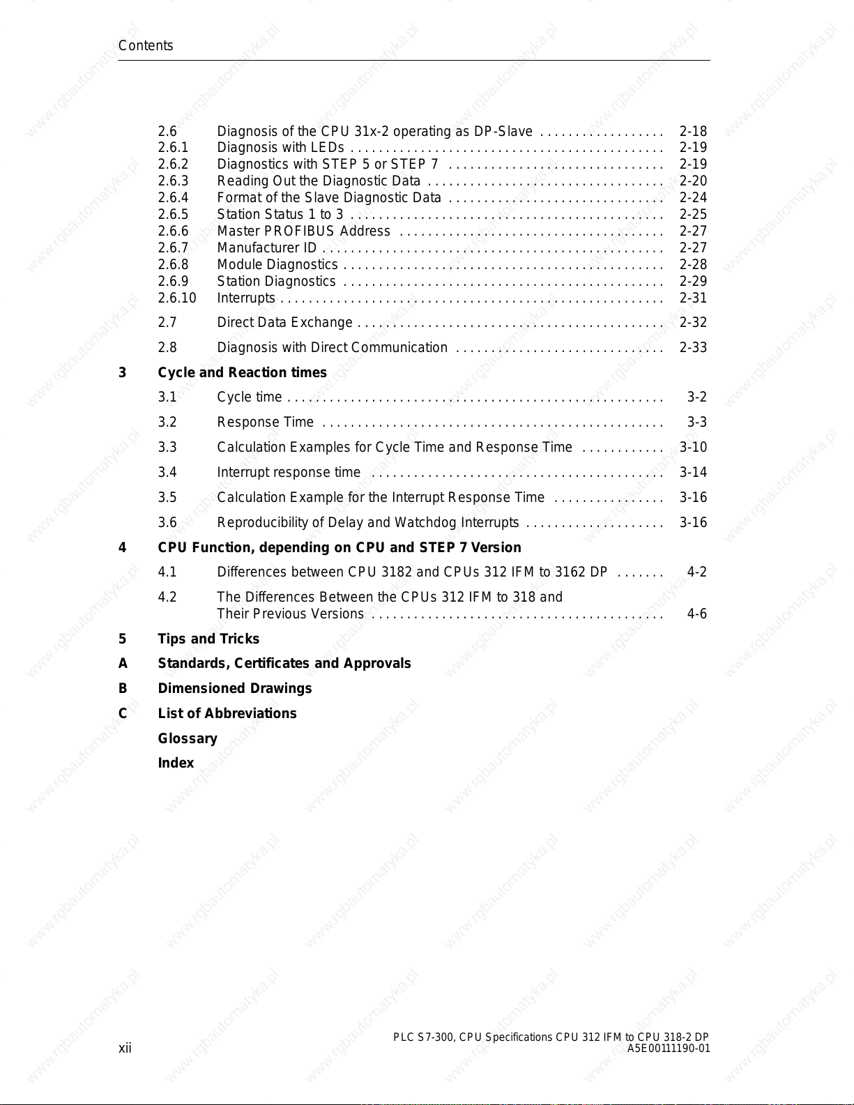
2.6 Diagnosis of the CPU 31x-2 operating as DP-Slave 2-18 . . . . . . . . . . . . . . . . . .
2.6.1 Diagnosis with LEDs 2-19 . . . . . . . . . . . . . . . . . . . . . . . . . . . . . . . . . . . . . . . . . . . . .
2.6.2 Diagnostics with STEP 5 or STEP 7 2-19 . . . . . . . . . . . . . . . . . . . . . . . . . . . . . . .
2.6.3 Reading Out the Diagnostic Data 2-20 . . . . . . . . . . . . . . . . . . . . . . . . . . . . . . . . . .
2.6.4 Format of the Slave Diagnostic Data 2-24 . . . . . . . . . . . . . . . . . . . . . . . . . . . . . . .
2.6.5 Station Status 1 to 3 2-25 . . . . . . . . . . . . . . . . . . . . . . . . . . . . . . . . . . . . . . . . . . . . .
2.6.6 Master PROFIBUS Address 2-27 . . . . . . . . . . . . . . . . . . . . . . . . . . . . . . . . . . . . . .
2.6.7 Manufacturer ID 2-27 . . . . . . . . . . . . . . . . . . . . . . . . . . . . . . . . . . . . . . . . . . . . . . . . .
2.6.8 Module Diagnostics 2-28 . . . . . . . . . . . . . . . . . . . . . . . . . . . . . . . . . . . . . . . . . . . . . .
2.6.9 Station Diagnostics 2-29 . . . . . . . . . . . . . . . . . . . . . . . . . . . . . . . . . . . . . . . . . . . . . .
2.6.10 Interrupts 2-31 . . . . . . . . . . . . . . . . . . . . . . . . . . . . . . . . . . . . . . . . . . . . . . . . . . . . . . .
2.7 Direct Data Exchange 2-32 . . . . . . . . . . . . . . . . . . . . . . . . . . . . . . . . . . . . . . . . . . . .
2.8 Diagnosis with Direct Communication 2-33 . . . . . . . . . . . . . . . . . . . . . . . . . . . . . .
3 Cycle and Reaction times
3.1 Cycle time 3-2 . . . . . . . . . . . . . . . . . . . . . . . . . . . . . . . . . . . . . . . . . . . . . . . . . . . . . .
3.2 Response Time 3-3 . . . . . . . . . . . . . . . . . . . . . . . . . . . . . . . . . . . . . . . . . . . . . . . . .
3.3 Calculation Examples for Cycle Time and Response Time 3-10 . . . . . . . . . . . .
3.4 Interrupt response time 3-14 . . . . . . . . . . . . . . . . . . . . . . . . . . . . . . . . . . . . . . . . . .
3.5 Calculation Example for the Interrupt Response Time 3-16 . . . . . . . . . . . . . . . .
3.6 Reproducibility of Delay and Watchdog Interrupts 3-16 . . . . . . . . . . . . . . . . . . . .
4 CPU Function, depending on CPU and STEP 7 Version
4.1 Differences between CPU 3182 and CPUs 312 IFM to 3162 DP 4-2 . . . . . . .
4.2 The Differences Between the CPUs 312 IFM to 318 and
Their Previous Versions 4-6 . . . . . . . . . . . . . . . . . . . . . . . . . . . . . . . . . . . . . . . . . .
5 Tips and Tricks
A Standards, Certificates and Approvals
B Dimensioned Drawings
C List of Abbreviations
Glossary
Index
xii
PLC S7-300, CPU Specifications CPU 312 IFM to CPU 318-2 DP
A5E00111190-01
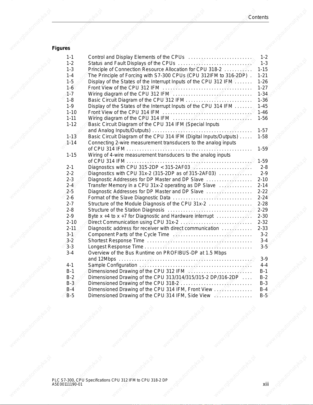
Figures
1-1 Control and Display Elements of the CPUs 1-2 . . . . . . . . . . . . . . . . . . . . . . . . .
1-2 Status and Fault Displays of the CPUs 1-3 . . . . . . . . . . . . . . . . . . . . . . . . . . . . .
1-3 Principle of Connection Resource Allocation for CPU 318-2 1-15 . . . . . . . . . . .
1-4 The Principle of Forcing with S7-300 CPUs (CPU 312IFM to 316-2DP) 1-21 .
1-5 Display of the States of the Interrupt Inputs of the CPU 312 IFM 1-26 . . . . . . .
1-6 Front View of the CPU 312 IFM 1-27 . . . . . . . . . . . . . . . . . . . . . . . . . . . . . . . . . . .
1-7 Wiring diagram of the CPU 312 IFM 1-34 . . . . . . . . . . . . . . . . . . . . . . . . . . . . . . .
1-8 Basic Circuit Diagram of the CPU 312 IFM 1-36 . . . . . . . . . . . . . . . . . . . . . . . . . .
1-9 Display of the States of the Interrupt Inputs of the CPU 314 IFM 1-45 . . . . . . .
1-10 Front View of the CPU 314 IFM 1-46 . . . . . . . . . . . . . . . . . . . . . . . . . . . . . . . . . . .
1-11 Wiring diagram of the CPU 314 IFM 1-56 . . . . . . . . . . . . . . . . . . . . . . . . . . . . . . .
1-12 Basic Circuit Diagram of the CPU 314 IFM (Special Inputs
and Analog Inputs/Outputs) 1-57 . . . . . . . . . . . . . . . . . . . . . . . . . . . . . . . . . . . . . . .
1-13 Basic Circuit Diagram of the CPU 314 IFM (Digital Inputs/Outputs) 1-58 . . . . .
1-14 Connecting 2-wire measurement transducers to the analog inputs
of CPU 314 IFM 1-59 . . . . . . . . . . . . . . . . . . . . . . . . . . . . . . . . . . . . . . . . . . . . . . . . .
1-15 Wiring of 4-wire measurement transducers to the analog inputs
of CPU 314 IFM 1-59 . . . . . . . . . . . . . . . . . . . . . . . . . . . . . . . . . . . . . . . . . . . . . . . . .
2-1 Diagnostics with CPU 315-2DP < 315-2AF03 2-8 . . . . . . . . . . . . . . . . . . . . . . .
2-2 Diagnostics with CPU 31x-2 (315-2DP as of 315-2AF03) 2-9 . . . . . . . . . . . . .
2-3 Diagnostic Addresses for DP Master and DP Slave 2-10 . . . . . . . . . . . . . . . . . .
2-4 Transfer Memory in a CPU 31x-2 operating as DP Slave 2-14 . . . . . . . . . . . . .
2-5 Diagnostic Addresses for DP Master and DP Slave 2-22 . . . . . . . . . . . . . . . . . .
2-6 Format of the Slave Diagnostic Data 2-24 . . . . . . . . . . . . . . . . . . . . . . . . . . . . . . .
2-7 Structure of the Module Diagnosis of the CPU 31x-2 2-28 . . . . . . . . . . . . . . . . .
2-8 Structure of the Station Diagnosis 2-29 . . . . . . . . . . . . . . . . . . . . . . . . . . . . . . . . .
2-9 Byte x +4 to x +7 for Diagnostic and Hardware interrupt 2-30 . . . . . . . . . . . . . .
2-10 Direct Communication using CPU 31x-2 2-32 . . . . . . . . . . . . . . . . . . . . . . . . . . . .
2-11 Diagnostic address for receiver with direct communication 2-33 . . . . . . . . . . . .
3-1 Component Parts of the Cycle Time 3-2 . . . . . . . . . . . . . . . . . . . . . . . . . . . . . . .
3-2 Shortest Response Time 3-4 . . . . . . . . . . . . . . . . . . . . . . . . . . . . . . . . . . . . . . . . .
3-3 Longest Response Time 3-5 . . . . . . . . . . . . . . . . . . . . . . . . . . . . . . . . . . . . . . . . . .
3-4 Overview of the Bus Runtime on PROFIBUS-DP at 1.5 Mbps
and 12Mbps 3-9 . . . . . . . . . . . . . . . . . . . . . . . . . . . . . . . . . . . . . . . . . . . . . . . . . . . .
4-1 Sample Configuration 4-4 . . . . . . . . . . . . . . . . . . . . . . . . . . . . . . . . . . . . . . . . . . . .
B-1 Dimensioned Drawing of the CPU 312 IFM B-1 . . . . . . . . . . . . . . . . . . . . . . . . .
B-2 Dimensioned Drawing of the CPU 313/314/315/315-2 DP/316-2DP B-2 . . . .
B-3 Dimensioned Drawing of the CPU 318-2 B-3 . . . . . . . . . . . . . . . . . . . . . . . . . . . .
B-4 Dimensioned Drawing of the CPU 314 IFM, Front View B-4 . . . . . . . . . . . . . . .
B-5 Dimensioned Drawing of the CPU 314 IFM, Side View B-5 . . . . . . . . . . . . . . .
Contents
PLC S7-300, CPU Specifications CPU 312 IFM to CPU 318-2 DP
A5E00111190-01
xiii
Contents
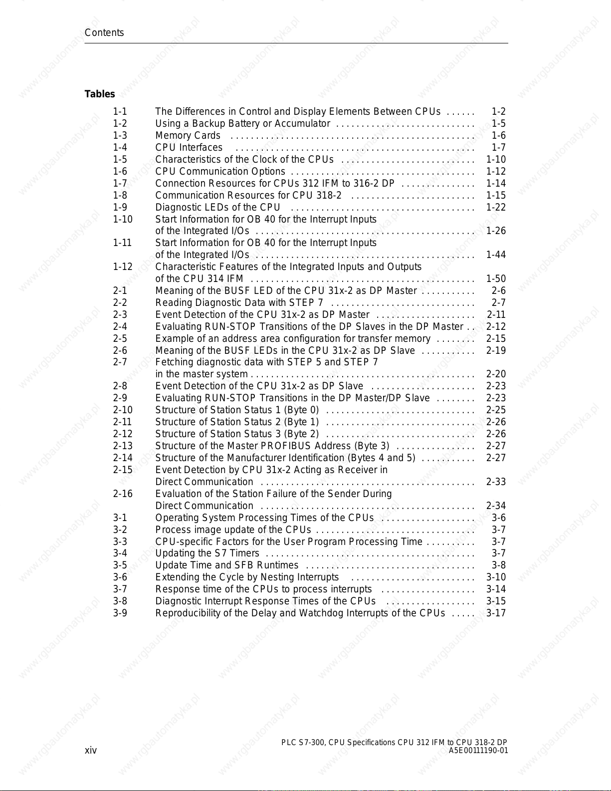
Tables
1-1 The Differences in Control and Display Elements Between CPUs 1-2 . . . . . .
1-2 Using a Backup Battery or Accumulator 1-5 . . . . . . . . . . . . . . . . . . . . . . . . . . . .
1-3 Memory Cards 1-6 . . . . . . . . . . . . . . . . . . . . . . . . . . . . . . . . . . . . . . . . . . . . . . . . .
1-4 CPU Interfaces 1-7 . . . . . . . . . . . . . . . . . . . . . . . . . . . . . . . . . . . . . . . . . . . . . . . .
1-5 Characteristics of the Clock of the CPUs 1-10 . . . . . . . . . . . . . . . . . . . . . . . . . . .
1-6 CPU Communication Options 1-12 . . . . . . . . . . . . . . . . . . . . . . . . . . . . . . . . . . . . .
1-7 Connection Resources for CPUs 312 IFM to 316-2 DP 1-14 . . . . . . . . . . . . . . .
1-8 Communication Resources for CPU 318-2 1-15 . . . . . . . . . . . . . . . . . . . . . . . . .
1-9 Diagnostic LEDs of the CPU 1-22 . . . . . . . . . . . . . . . . . . . . . . . . . . . . . . . . . . . . .
1-10 Start Information for OB 40 for the Interrupt Inputs
of the Integrated I/Os 1-26 . . . . . . . . . . . . . . . . . . . . . . . . . . . . . . . . . . . . . . . . . . . .
1-11 Start Information for OB 40 for the Interrupt Inputs
of the Integrated I/Os 1-44 . . . . . . . . . . . . . . . . . . . . . . . . . . . . . . . . . . . . . . . . . . . .
1-12 Characteristic Features of the Integrated Inputs and Outputs
of the CPU 314 IFM 1-50 . . . . . . . . . . . . . . . . . . . . . . . . . . . . . . . . . . . . . . . . . . . . .
2-1 Meaning of the BUSF LED of the CPU 31x-2 as DP Master 2-6 . . . . . . . . . . .
2-2 Reading Diagnostic Data with STEP 7 2-7 . . . . . . . . . . . . . . . . . . . . . . . . . . . . .
2-3 Event Detection of the CPU 31x-2 as DP Master 2-11 . . . . . . . . . . . . . . . . . . . .
2-4 Evaluating RUN-STOP Transitions of the DP Slaves in the DP Master 2-12 . .
2-5 Example of an address area configuration for transfer memory 2-15 . . . . . . . .
2-6 Meaning of the BUSF LEDs in the CPU 31x-2 as DP Slave 2-19 . . . . . . . . . . .
2-7 Fetching diagnostic data with STEP 5 and STEP 7
in the master system 2-20 . . . . . . . . . . . . . . . . . . . . . . . . . . . . . . . . . . . . . . . . . . . . .
2-8 Event Detection of the CPU 31x-2 as DP Slave 2-23 . . . . . . . . . . . . . . . . . . . . .
2-9 Evaluating RUN-STOP Transitions in the DP Master/DP Slave 2-23 . . . . . . . .
2-10 Structure of Station Status 1 (Byte 0) 2-25 . . . . . . . . . . . . . . . . . . . . . . . . . . . . . .
2-11 Structure of Station Status 2 (Byte 1) 2-26 . . . . . . . . . . . . . . . . . . . . . . . . . . . . . .
2-12 Structure of Station Status 3 (Byte 2) 2-26 . . . . . . . . . . . . . . . . . . . . . . . . . . . . . .
2-13 Structure of the Master PROFIBUS Address (Byte 3) 2-27 . . . . . . . . . . . . . . . .
2-14 Structure of the Manufacturer Identification (Bytes 4 and 5) 2-27 . . . . . . . . . . .
2-15 Event Detection by CPU 31x-2 Acting as Receiver in
Direct Communication 2-33 . . . . . . . . . . . . . . . . . . . . . . . . . . . . . . . . . . . . . . . . . . .
2-16 Evaluation of the Station Failure of the Sender During
Direct Communication 2-34 . . . . . . . . . . . . . . . . . . . . . . . . . . . . . . . . . . . . . . . . . . .
3-1 Operating System Processing Times of the CPUs 3-6 . . . . . . . . . . . . . . . . . . .
3-2 Process image update of the CPUs 3-7 . . . . . . . . . . . . . . . . . . . . . . . . . . . . . . . .
3-3 CPU-specific Factors for the User Program Processing Time 3-7 . . . . . . . . . .
3-4 Updating the S7 Timers 3-7 . . . . . . . . . . . . . . . . . . . . . . . . . . . . . . . . . . . . . . . . . .
3-5 Update Time and SFB Runtimes 3-8 . . . . . . . . . . . . . . . . . . . . . . . . . . . . . . . . . .
3-6 Extending the Cycle by Nesting Interrupts 3-10 . . . . . . . . . . . . . . . . . . . . . . . . .
3-7 Response time of the CPUs to process interrupts 3-14 . . . . . . . . . . . . . . . . . . .
3-8 Diagnostic Interrupt Response Times of the CPUs 3-15 . . . . . . . . . . . . . . . . . .
3-9 Reproducibility of the Delay and Watchdog Interrupts of the CPUs 3-17 . . . . .
xiv
PLC S7-300, CPU Specifications CPU 312 IFM to CPU 318-2 DP
A5E00111190-01
CPUs
In This Section
Section Contents Page
1.1 Control and Display Elements 1-2
1.2 CPU Communication Options 1-11
1.3 Test Functions and Diagnostics 1-19
1.4 CPUs - Technical Specifications 1-24
Agreement for CPU 314IFM
The CPU 314IFM is available in 2 versions:
with slot for memory card (6ES7314-5EA10-0AB0)
without slot for memory card (6ES7314-5EA0x-0AB0/
6314ES7314-5EA8x-0AB0)
All details in this chapter apply to both versions of the CPU314IFM unless explicit
reference is made to differences between them.
1
PLC S7-300, CPU Specifications CPU 312 IFM to CPU 318-2 DP
A5E00111190-01
1-1
CPUs
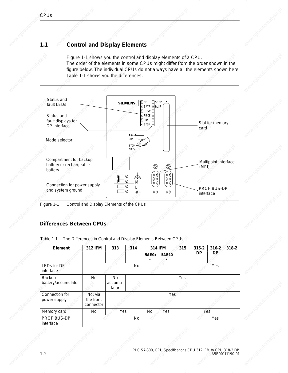
1.1 Control and Display Elements
Figure 1-1 shows you the control and display elements of a CPU.
The order of the elements in some CPUs might differ from the order shown in the
figure below. The individual CPUs do not always have all the elements shown here.
Table 1-1 shows you the differences.
Status and
fault LEDs
Status and
fault displays for
DP interface
Mode selector
Slot for memory
card
Compartment for backup
battery or rechargeable
battery
Connection for power supply
and system ground
Figure 1-1 Control and Display Elements of the CPUs
M
L
+M
Multipoint Interface
(MPI)
PROFIBUS-DP
interface
Differences Between CPUs
Table 1-1 The Differences in Control and Display Elements Between CPUs
Element 312 IFM 313 314
LEDs for DP
interface
Backup
battery/accumulator
Connection for
power supply
Memory card No Yes No Yes Yes
PROFIBUS-DP
interface
No No
accumu-
lator
No; via
the front
connector
No Yes
No Yes
314 IFM
-5AE0x--5AE10
315 315-2 316-2 318-2
DP DP
-
Yes
Yes
1-2
PLC S7-300, CPU Specifications CPU 312 IFM to CPU 318-2 DP
A5E00111190-01
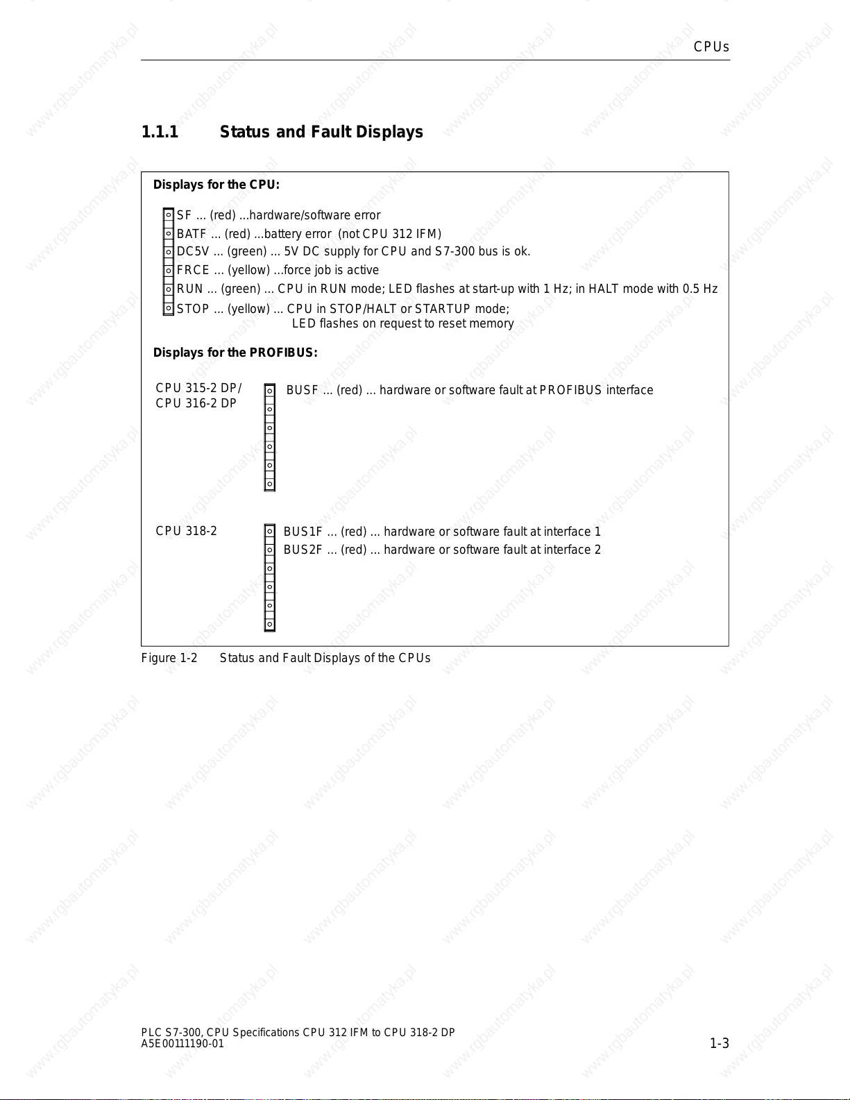
1.1.1 Status and Fault Displays
Displays for the CPU:
SF ... (red) ...hardware/software error
BATF ... (red) ...battery error (not CPU 312 IFM)
DC5V ... (green) ... 5V DC supply for CPU and S7-300 bus is ok.
FRCE ... (yellow) ...force job is active
RUN ... (green) ... CPU in RUN mode; LED flashes at start-up with 1 Hz; in HALT mode with 0.5 Hz
STOP ... (yellow) ... CPU in STOP/HALT or STARTUP mode;
LED flashes on request to reset memory
Displays for the PROFIBUS:
CPUs
CPU 315-2 DP/
CPU 316-2 DP
CPU 318-2
Figure 1-2 Status and Fault Displays of the CPUs
BUSF ... (red) ... hardware or software fault at PROFIBUS interface
BUS1F ... (red) ... hardware or software fault at interface 1
BUS2F ... (red) ... hardware or software fault at interface 2
PLC S7-300, CPU Specifications CPU 312 IFM to CPU 318-2 DP
A5E00111190-01
1-3
CPUs
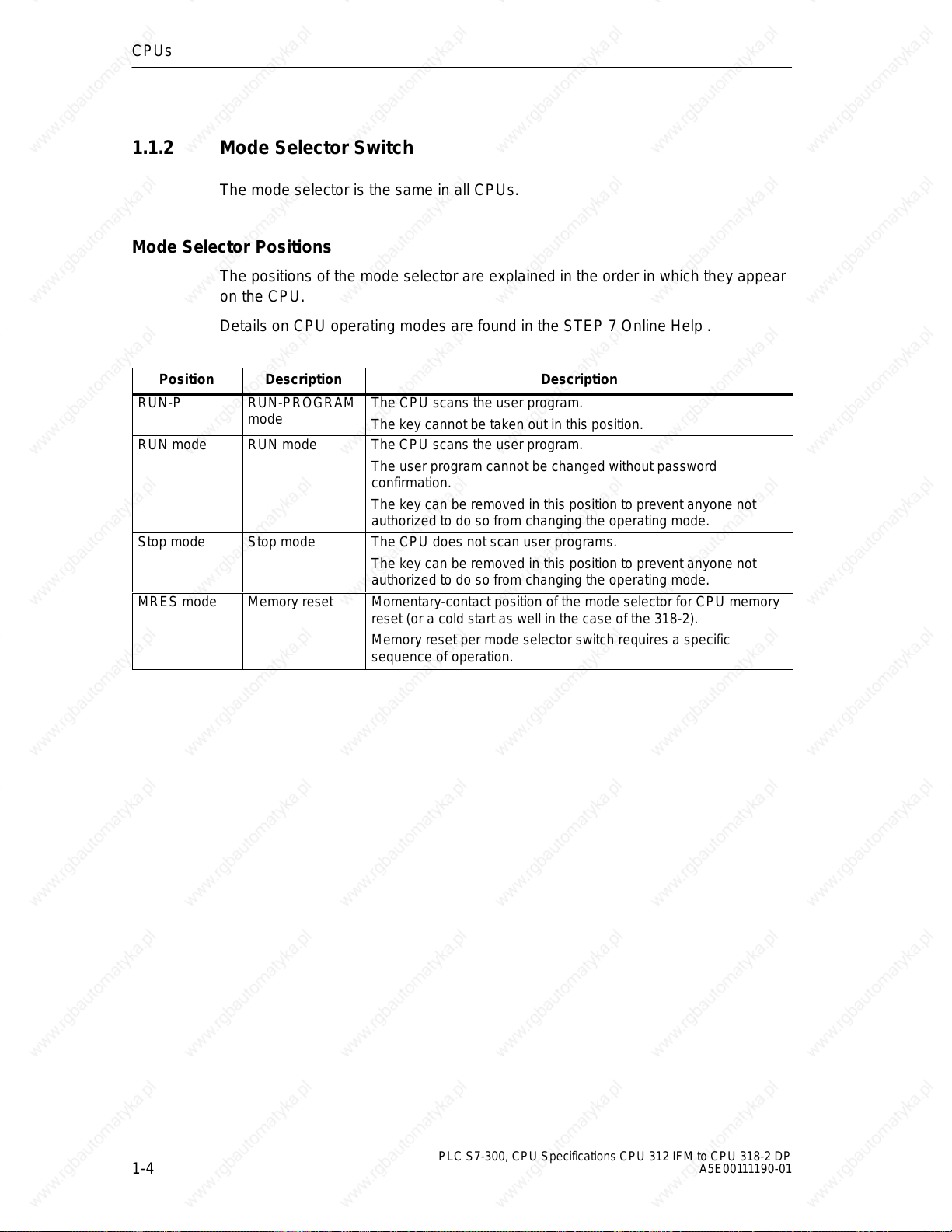
1.1.2 Mode Selector Switch
The mode selector is the same in all CPUs.
Mode Selector Positions
The positions of the mode selector are explained in the order in which they appear
on the CPU.
Details on CPU operating modes are found in the STEP 7 Online Help .
Position Description Description
RUN-P RUN-PROGRAM
mode
RUN mode RUN mode The CPU scans the user program.
Stop mode Stop mode The CPU does not scan user programs.
MRES mode Memory reset Momentary-contact position of the mode selector for CPU memory
The CPU scans the user program.
The key cannot be taken out in this position.
The user program cannot be changed without password
confirmation.
The key can be removed in this position to prevent anyone not
authorized to do so from changing the operating mode.
The key can be removed in this position to prevent anyone not
authorized to do so from changing the operating mode.
reset (or a cold start as well in the case of the 318-2).
Memory reset per mode selector switch requires a specific
sequence of operation.
1-4
PLC S7-300, CPU Specifications CPU 312 IFM to CPU 318-2 DP
A5E00111190-01
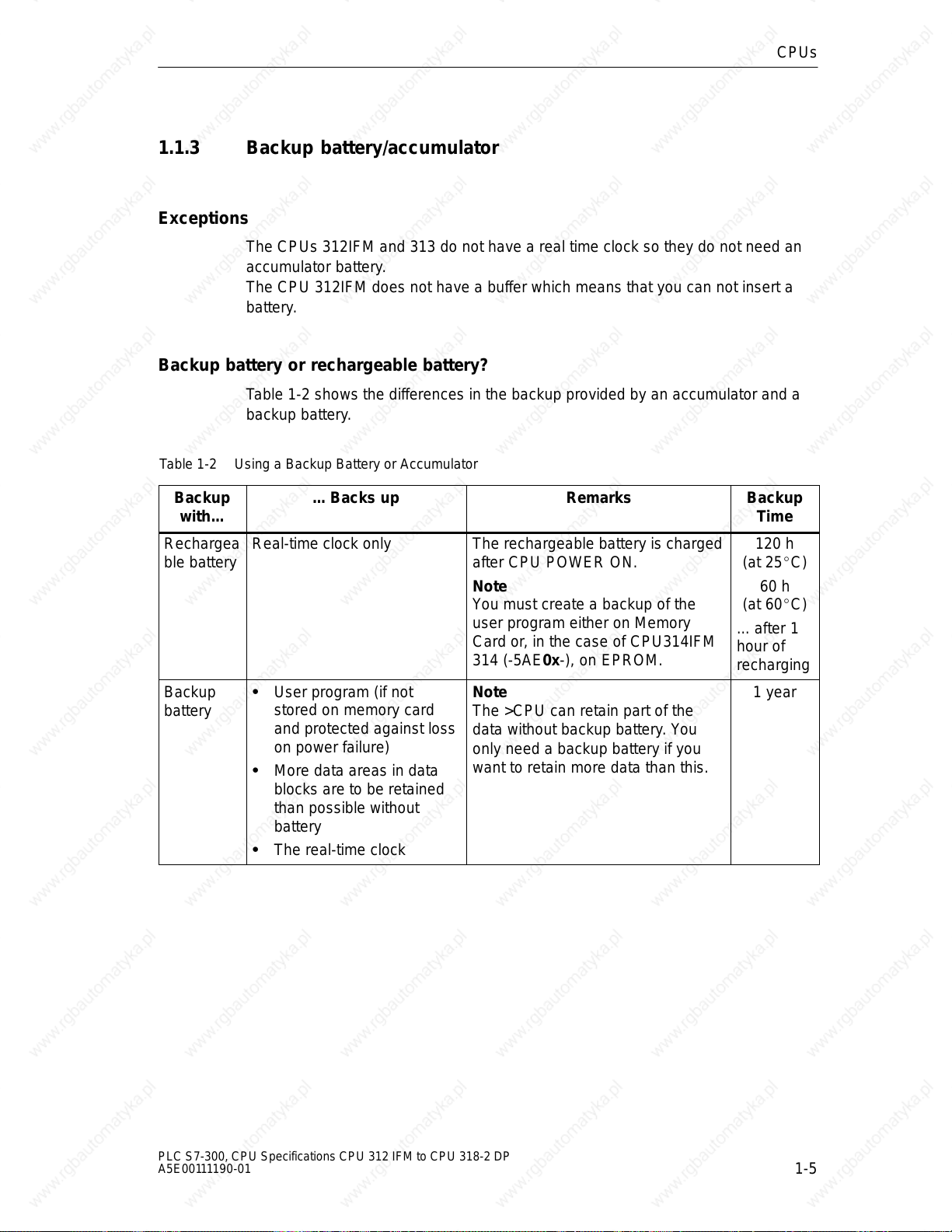
1.1.3 Backup battery/accumulator
Exceptions
The CPUs 312IFM and 313 do not have a real time clock so they do not need an
accumulator battery.
The CPU 312IFM does not have a buffer which means that you can not insert a
battery.
Backup battery or rechargeable battery?
Table 1-2 shows the differences in the backup provided by an accumulator and a
backup battery.
Table 1-2 Using a Backup Battery or Accumulator
CPUs
Backup
with...
Rechargea
ble battery
Backup
battery
... Backs up Remarks Backup
Real-time clock only The rechargeable battery is charged
after CPU POWER ON.
Note
You must create a backup of the
user program either on Memory
Card or, in the case of CPU314IFM
314 (-5AE0x-), on EPROM.
User program (if not
stored on memory card
and protected against loss
on power failure)
More data areas in data
blocks are to be retained
than possible without
battery
Note
The >CPU can retain part of the
data without backup battery. You
only need a backup battery if you
want to retain more data than this.
The real-time clock
Time
120 h
(at 25C)
60 h
(at 60C)
... after 1
hour of
recharging
1 year
PLC S7-300, CPU Specifications CPU 312 IFM to CPU 318-2 DP
A5E00111190-01
1-5
CPUs
then uploaded from the memory card to
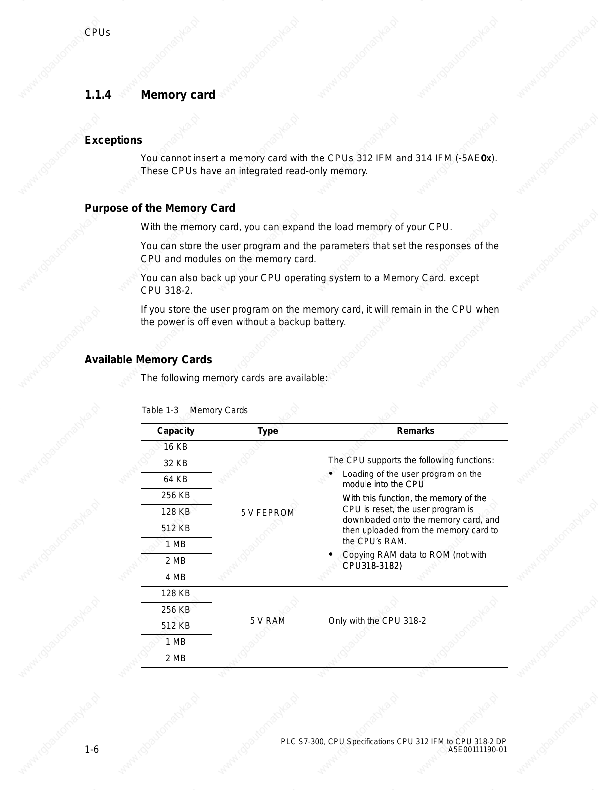
1.1.4 Memory card
Exceptions
You cannot insert a memory card with the CPUs 312 IFM and 314 IFM (-5AE0x).
These CPUs have an integrated read-only memory.
Purpose of the Memory Card
With the memory card, you can expand the load memory of your CPU.
You can store the user program and the parameters that set the responses of the
CPU and modules on the memory card.
You can also back up your CPU operating system to a Memory Card. except
CPU 318-2.
If you store the user program on the memory card, it will remain in the CPU when
the power is off even without a backup battery.
Available Memory Cards
The following memory cards are available:
Table 1-3 Memory Cards
Capacity
16 KB
32 KB
64 KB
256 KB
128 KB
512 KB
1 MB
2 MB
4 MB
128 KB
256 KB
512 KB
1 MB
2 MB
Type Remarks
The CPU supports the following functions:
Loading of the user program on the
module into the CPU
module into the CPU
With this function, the memory of the
With this function, the memory of the
5 V FEPROM
CPU is reset, the user program is
downloaded onto the memory card, and
then uploaded from the memory card to
the CPU’s RAM.
Copying RAM data to ROM (not with
CPU318-3182)
CPU318-3182)
5 V RAM Only with the CPU 318-2
1-6
PLC S7-300, CPU Specifications CPU 312 IFM to CPU 318-2 DP
A5E00111190-01
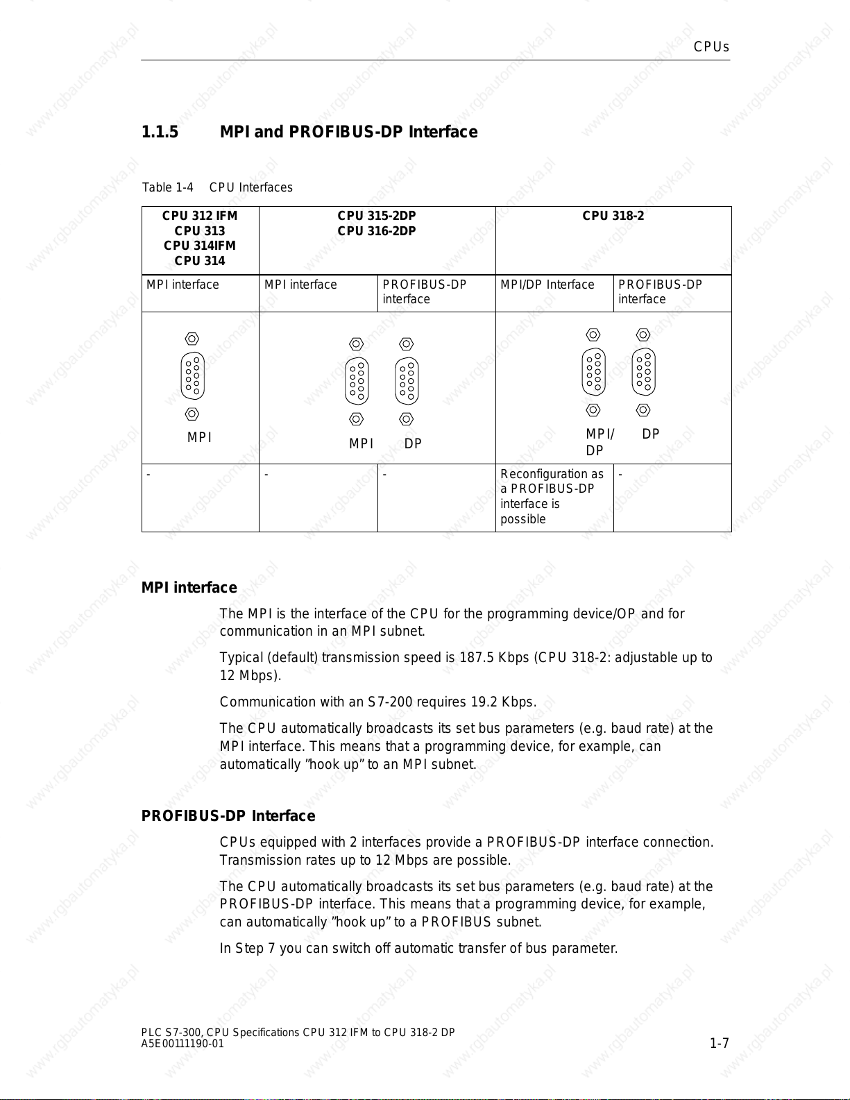
1.1.5 MPI and PROFIBUS-DP Interface
Table 1-4 CPU Interfaces
CPUs
CPU 312 IFM
CPU 313
CPU 314IFM
CPU 314
MPI interface MPI interface PROFIBUS-DP
MPI
- - - Reconfiguration as
CPU 315-2DP
CPU 316-2DP
MPI/DP Interface PROFIBUS-DP
interface
MPI DP
a PROFIBUS-DP
interface is
possible
CPU 318-2
MPI interface
The MPI is the interface of the CPU for the programming device/OP and for
communication in an MPI subnet.
MPI/
DP
interface
DP
-
Typical (default) transmission speed is 187.5 Kbps (CPU 318-2: adjustable up to
12 Mbps).
Communication with an S7-200 requires 19.2 Kbps.
The CPU automatically broadcasts its set bus parameters (e.g. baud rate) at the
MPI interface. This means that a programming device, for example, can
automatically ”hook up” to an MPI subnet.
PROFIBUS-DP Interface
CPUs equipped with 2 interfaces provide a PROFIBUS-DP interface connection.
Transmission rates up to 12 Mbps are possible.
The CPU automatically broadcasts its set bus parameters (e.g. baud rate) at the
PROFIBUS-DP interface. This means that a programming device, for example,
can automatically ”hook up” to a PROFIBUS subnet.
In Step 7 you can switch off automatic transfer of bus parameter.
PLC S7-300, CPU Specifications CPU 312 IFM to CPU 318-2 DP
A5E00111190-01
1-7
CPUs
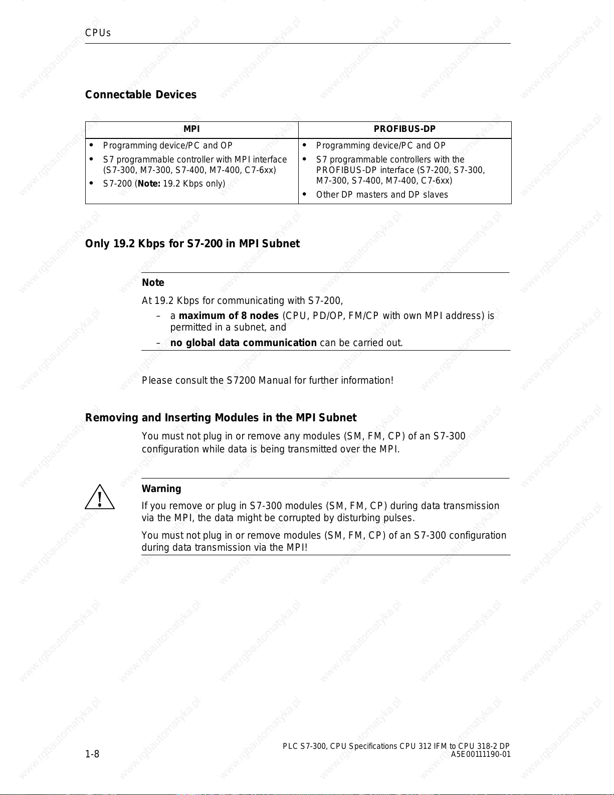
Connectable Devices
MPI PROFIBUS-DP
Programming device/PC and OP
S7 programmable controller with MPI interface
(S7-300, M7-300, S7-400, M7-400, C7-6xx)
S7-200 (Note: 19.2 Kbps only)
Only 19.2 Kbps for S7-200 in MPI Subnet
Note
At 19.2 Kbps for communicating with S7-200,
– a maximum of 8 nodes (CPU, PD/OP, FM/CP with own MPI address) is
permitted in a subnet, and
– no global data communication can be carried out.
Programming device/PC and OP
S7 programmable controllers with the
PROFIBUS-DP interface (S7-200, S7-300,
M7-300, S7-400, M7-400, C7-6xx)
Other DP masters and DP slaves
Please consult the S7200 Manual for further information!
Removing and Inserting Modules in the MPI Subnet
You must not plug in or remove any modules (SM, FM, CP) of an S7-300
configuration while data is being transmitted over the MPI.
Warning
!
If you remove or plug in S7-300 modules (SM, FM, CP) during data transmission
via the MPI, the data might be corrupted by disturbing pulses.
You must not plug in or remove modules (SM, FM, CP) of an S7-300 configuration
during data transmission via the MPI!
1-8
PLC S7-300, CPU Specifications CPU 312 IFM to CPU 318-2 DP
A5E00111190-01

Loss of GD packets Following Change in the MPI Subnet During Operation
Warning
!
Loss of data packets in the MPI subnet:
Connecting an additional CPU to the MPI subnet during operation can lead to loss
of GD packets and to an increase in cycle time.
Remedy:
1. Disconnect the node to be connected from the supply.
2. Connect the node to the MPI subnet.
3. Switch the node on.
CPUs
PLC S7-300, CPU Specifications CPU 312 IFM to CPU 318-2 DP
A5E00111190-01
1-9
CPUs
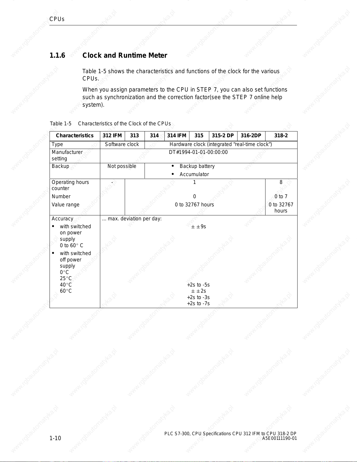
1.1.6 Clock and Runtime Meter
Table 1-5 shows the characteristics and functions of the clock for the various
CPUs.
When you assign parameters to the CPU in STEP 7, you can also set functions
such as synchronization and the correction factor(see the STEP 7 online help
system).
Table 1-5 Characteristics of the Clock of the CPUs
Characteristics
Type Software clock Hardware clock (integrated “real-time clock”)
Manufacturer
setting
Backup Not possible Backup battery
312 IFM 313 314 314 IFM 315 315-2 DP 316-2DP 318-2
DT#1994-01-01-00:00:00
Accumulator
Operating hours
counter
Number
Value range
Accuracy
with switched
on power
supply
0 to 60 C
with switched
off power
supply
0C
25C
40C
60C
- 1
0
0 to 32767 hours
... max. deviation per day:
9s
+2s to -5s
2s
+2s to -3s
+2s to -7s
8
0 to 7
0 to 32767
hours
1-10
PLC S7-300, CPU Specifications CPU 312 IFM to CPU 318-2 DP
A5E00111190-01
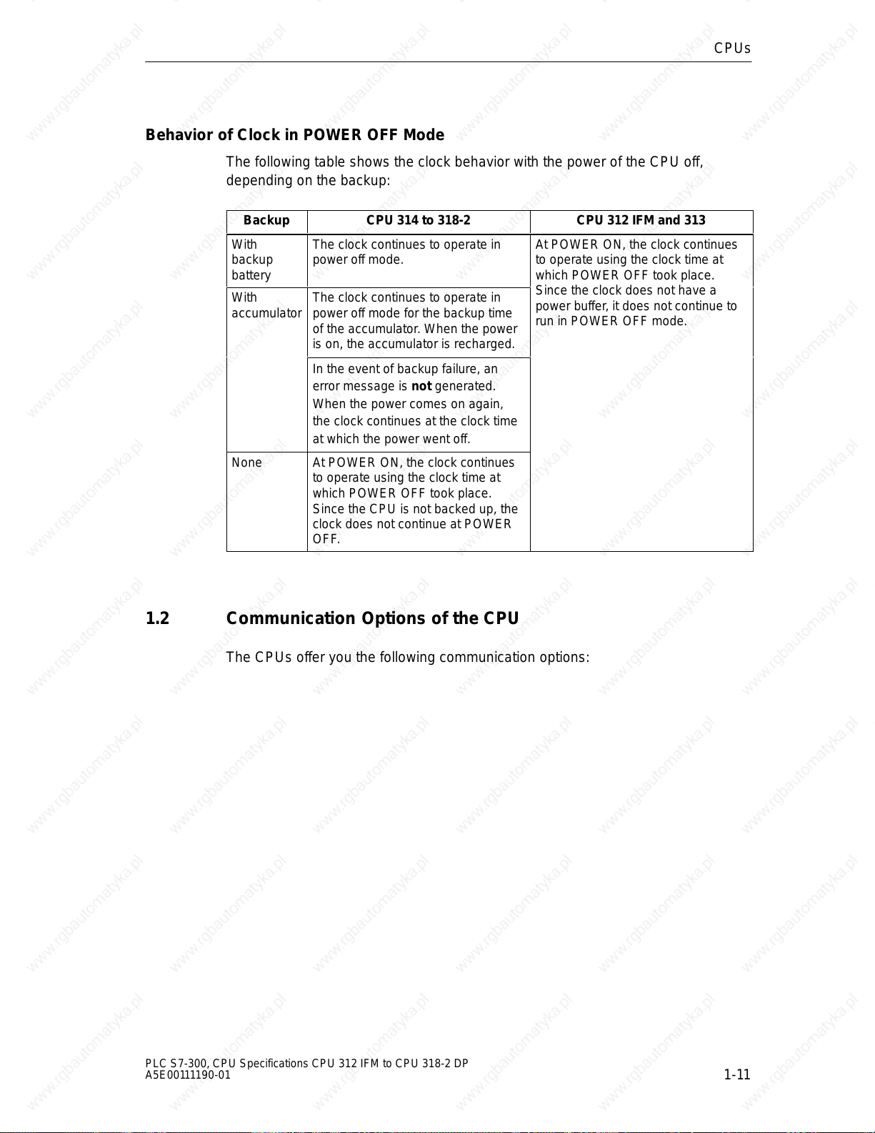
Behavior of Clock in POWER OFF Mode
The following table shows the clock behavior with the power of the CPU off,
depending on the backup:
Backup CPU 314 to 318-2 CPU 312 IFM and 313
With
backup
battery
With
accumulator
None At POWER ON, the clock continues
The clock continues to operate in
power off mode.
The clock continues to operate in
power off mode for the backup time
of the accumulator. When the power
is on, the accumulator is recharged.
In the event of backup failure, an
error message is not generated.
When the power comes on again,
the clock continues at the clock time
at which the power went off.
to operate using the clock time at
which POWER OFF took place.
Since the CPU is not backed up, the
clock does not continue at POWER
OFF.
CPUs
At POWER ON, the clock continues
to operate using the clock time at
which POWER OFF took place.
Since the clock does not have a
power buffer, it does not continue to
run in POWER OFF mode.
1.2 Communication Options of the CPU
The CPUs offer you the following communication options:
PLC S7-300, CPU Specifications CPU 312 IFM to CPU 318-2 DP
A5E00111190-01
1-11
CPUs
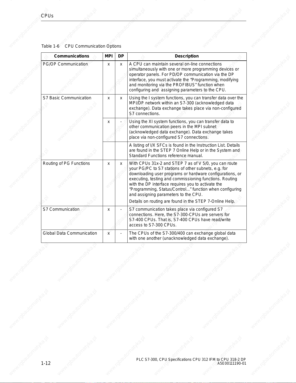
Table 1-6 CPU Communication Options
Communications
PG/OP Communication x x A CPU can maintain several on-line connections
S7 Basic Communication x x Using the I system functions, you can transfer data over the
Routing of PG Functions x x With CPUs 31x-2 and STEP 7 as of V 5/0, you can route
S7 Communication x - S7 communication takes place via configured S7
Global Data Communication x - The CPUs of the S7-300/400 can exchange global data
MPI DP Description
simultaneously with one or more programming devices or
operator panels. For PD/OP communication via the DP
interface, you must activate the “Programming, modifying
and monitoring via the PROFIBUS” function when
configuring and assigning parameters to the CPU.
MPI/DP network within an S7-300 (acknowledged data
exchange). Data exchange takes place via non-configured
S7 connections.
x - Using the XI system functions, you can transfer data to
other communication peers in the MPI subnet
(acknowledged data exchange). Data exchange takes
place via non-configured S7 connections.
A listing of I/X SFCs is found in the Instruction List. Details
are found in the STEP 7 Online Help or in the System and
Standard Functions reference manual.
your PG/PC to S7 stations of other subnets, e.g. for
downloading user programs or hardware configurations, or
executing, testing and commissioning functions. Routing
with the DP interface requires you to activate the
“Programming, Status/Control...” function when configuring
and assigning parameters to the CPU.
Details on routing are found in the STEP 7-Online Help.
connections. Here, the S7-300-CPUs are servers for
S7-400 CPUs. That is, S7-400 CPUs have read/write
access to S7-300 CPUs.
with one another (unacknowledged data exchange).
1-12
PLC S7-300, CPU Specifications CPU 312 IFM to CPU 318-2 DP
A5E00111190-01
Connection Resources
Every communication connection requires a communication resource on the
S7 CPU as a management unit for the duration of the communication. Every
S7 CPU has a certain number of connection resources available to it according to
its technical specifications which can be assigned to various communication
services (PD/OP communication, S7 communication or S7 basic communication).
The distribution of connection resources differs between CPUs 312 IFM to 316-2
DP (see the table 3-6) and the CPU 318-2 (see Table 1-8):
CPUs
PLC S7-300, CPU Specifications CPU 312 IFM to CPU 318-2 DP
A5E00111190-01
1-13
CPUs
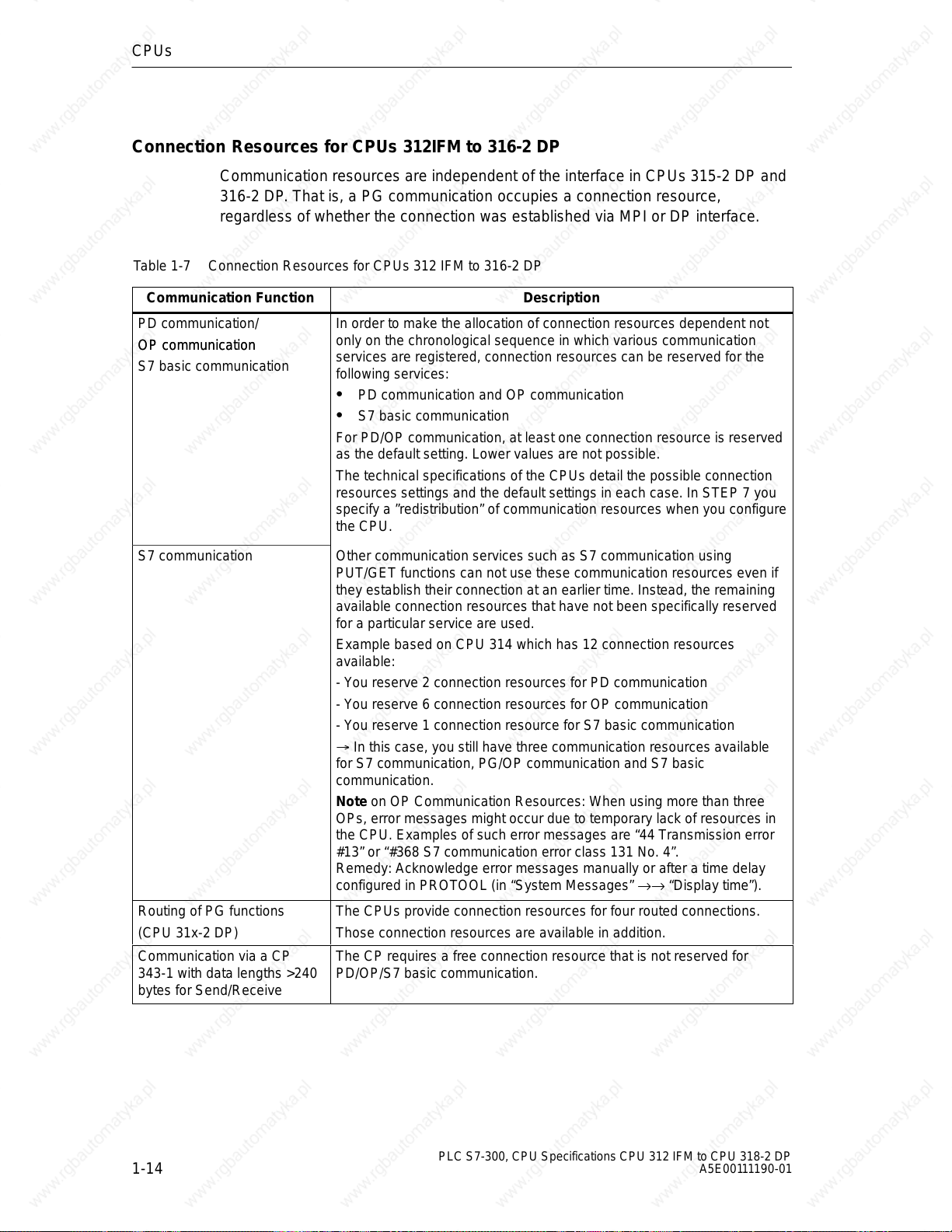
Connection Resources for CPUs 312IFM to 316-2 DP
Communication resources are independent of the interface in CPUs 315-2 DP and
316-2 DP. That is, a PG communication occupies a connection resource,
regardless of whether the connection was established via MPI or DP interface.
Table 1-7 Connection Resources for CPUs 312 IFM to 316-2 DP
Communication Function
PD communication/
OP communication
OP communication
S7 basic communication
In order to make the allocation of connection resources dependent not
only on the chronological sequence in which various communication
services are registered, connection resources can be reserved for the
following services:
Description
PD communication and OP communication
S7 basic communication
For PD/OP communication, at least one connection resource is reserved
as the default setting. Lower values are not possible.
The technical specifications of the CPUs detail the possible connection
resources settings and the default settings in each case. In STEP 7 you
specify a ”redistribution” of communication resources when you configure
the CPU.
S7 communication Other communication services such as S7 communication using
PUT/GET functions can not use these communication resources even if
they establish their connection at an earlier time. Instead, the remaining
available connection resources that have not been specifically reserved
for a particular service are used.
Example based on CPU 314 which has 12 connection resources
available:
- You reserve 2 connection resources for PD communication
- You reserve 6 connection resources for OP communication
- You reserve 1 connection resource for S7 basic communication
In this case, you still have three communication resources available
for S7 communication, PG/OP communication and S7 basic
communication.
Note on OP Communication Resources: When using more than three
OPs, error messages might occur due to temporary lack of resources in
the CPU. Examples of such error messages are “44 Transmission error
#13” or “#368 S7 communication error class 131 No. 4”.
Remedy: Acknowledge error messages manually or after a time delay
configured in PROTOOL (in “System Messages” →→ “Display time”).
Routing of PG functions The CPUs provide connection resources for four routed connections.
(CPU 31x-2 DP) Those connection resources are available in addition.
Communication via a CP
343-1 with data lengths >240
bytes for Send/Receive
The CP requires a free connection resource that is not reserved for
PD/OP/S7 basic communication.
1-14
PLC S7-300, CPU Specifications CPU 312 IFM to CPU 318-2 DP
A5E00111190-01
 Loading...