

Siemens Simatic S7 Series, Simatic S7-200 SMART Series System Manual

S7-200 SMART
___________________
___________________
___________________
___________________
___________________
___________________
___________________
___________________
___________________
___________________
___________________
___________________
___________________
___________________
___________________
___________________
___________________
___________________
___________________
SIMATIC
S7
S7-200 SMART
System Manual
09/2015
A5E03822230
Preface
Product overview
1
Getting started
2
Installation
3
PLC concepts
4
Programming concepts
5
PLC device configuration
6
Program instructions
7
Communication
8
Libraries
9
Debugging and
troubleshooting
10
PID loops and tuning
11
Open loop motion control
12
Technical specifications
A
Calculating a power budget
B
Error codes
C
Special memory (SM) and
system symbol names
D
References
E
Ordering information
F
-AC
Siemens AG
Division Digital Factory
Postfach 48 48
90026 NÜRNBERG
GERMANY
A5E03822230-AC
Ⓟ
Copyright © Siemens AG 2015.
All rights reserved
Legal information
Warning notice system
DANGER
indicates that death or severe personal injury will result if proper precautions are not taken.
WARNING
indicates that death or severe personal injury may result if proper precautions are not taken.
CAUTION
indicates that minor personal injury can result if proper precautions are not taken.
NOTICE
indicates that property damage can result if proper precautions are not taken.
Qualified Personnel
personnel qualified
Proper use of Siemens products
WARNING
Siemens products may only be used for the applications described in the catalog and in the relevant technical
ambient conditions must be complied with. The information in the relevant documentation must be observed.
Trademarks
Disclaimer of Liability
This manual contains notices you have to observe in order to ensure your personal safety, as well as to prevent
damage to property. The notices referring to your personal safety are highlighted in the manual by a safety alert
symbol, notices referring only to property damage have no safety alert symbol. These notices shown below are
graded according to the degree of danger.
If more than one degree of danger is present, the warning notice representing the highest degree of danger will
be used. A notice warning of injury to persons with a safety alert symbol may also include a warning relating to
property damage.
The product/system described in this documentation may be operated only by
task in accordance with the relevant documentation, in particular its warning notices and safety instructions.
Qualified personnel are those who, based on their training and experience, are capable of identifying risks and
avoiding potential hazards when working with these products/systems.
Note the following:
for the specific
documentation. If products and components from other manufacturers are used, these must be recommended
or approved by Siemens. Proper transport, storage, installation, assembly, commissioning, operation and
maintenance are required to ensure that the products operate safely and without any problems. The permissible
All names identified by ® are registered trademarks of Siemens AG. The remaining trademarks in this publication
may be trademarks whose use by third parties for their own purposes could violate the rights of the owner.
We have reviewed the contents of this publication to ensure consistency with the hardware and software
described. Since variance cannot be precluded entirely, we cannot guarantee full consistency. However, the
information in this publication is reviewed regularly and any necessary corrections are included in subsequent
editions.
07/2015 Subject to change

Preface
Purpose of the manual
Required basic knowledge
Scope of the manual
Certification, CE label and other standards
Service and support
The S7-200 SMART series is a line of micro-programmable logic controllers (Micro PLCs)
that can control a variety of automation applications. Compact design, low cost, and a
powerful instruction set make the S7-200 SMART a perfect solution for controlling small
applications. The wide variety of S7-200 SMART models and the Windows-based
programming tool give you the flexibility you need to solve your automation problems.
This manual provides information about installing and programming the S7-200 SMART
CPUs and is designed for engineers, programmers, installers, and electricians who have a
general knowledge of programmable logic controllers.
To understand this manual, it is necessary to have a general knowledge of automation and
programmable logic controllers.
This manual describes the following products:
● STEP 7-Micro/WIN SMART V2.01
● S7-200 SMART CPU firmware release V2.1
For a complete list of the S7-200 SMART products and article numbers described in this
manual, see Technical Specifications (Page 565).
Refer to the technical specifications for more information.
In addition to our documentation, we offer our technical expertise on the Internet on the
customer support web site (http://www.siemens.com/automation/).
Contact your Siemens distributor or sales office for assistance in answering any technical
questions, for training, or for ordering S7 products. Because your sales representatives are
technically trained and have the most specific knowledge about your operations, process
and industry, as well as about the individual Siemens products that you are using, they can
provide the fastest and most efficient answers to any problems you might encounter.
S7-200 SMART
System Manual, 09/2015, A5E03822230-AC
3

Preface
Security information
Siemens provides products and solutions with industrial security functions that support the
secure operation of plants, solutions, machines, equipment and/or networks. They are
important components in a holistic industrial security concept. With this in mind, Siemens’
products and solutions undergo continuous development. Siemens recommends strongly
that you regularly check for product updates.
For the secure operation of Siemens products and solutions, it is necessary to take suitable
preventive action (e.g. cell protection concept) and integrate each component into a holistic,
state-of-the-art industrial security concept. Third-party products that may be in use should
also be considered. You can find more information about industrial security on the Internet
(http://www.siemens.com/industrialsecurity).
To stay informed about product updates as they occur, sign up for a product-specific
newsletter. You can find more information on the Internet
(http://support.automation.siemens.com).
S7-200 SMART
4 System Manual, 09/2015, A5E03822230-AC

Table of contents
Preface ...................................................................................................................................................... 3
1 Product overview ..................................................................................................................................... 17
2 Getting started ......................................................................................................................................... 25
3 Installation ............................................................................................................................................... 37
1.1 S7-200 SMART CPU .............................................................................................................. 18
1.2 S7-200 SMART expansion modules ....................................................................................... 20
1.3 HMI devices for S7-200 SMART ............................................................................................. 21
1.4 Communications options ........................................................................................................ 22
1.5 Programming software ............................................................................................................ 23
1.6 New features ........................................................................................................................... 24
2.1 Connecting to the CPU ........................................................................................................... 25
2.1.1 Configuring the CPU for communication ................................................................................ 26
2.1.1.1 Overview ................................................................................................................................. 26
2.1.1.2 Establishing the hardware communication connection ........................................................... 27
2.1.1.3 Setting up communication with the CPU ................................................................................ 27
2.2 Creating the sample program ................................................................................................. 29
2.2.1 Network 1: Starting the timer .................................................................................................. 30
2.2.2 Network 2: Turning the output on ........................................................................................... 31
2.2.3 Network 3: Resetting the timer ............................................................................................... 32
2.2.4 Setting the CPU type and version for your project ................................................................. 33
2.2.5 Saving the sample project ...................................................................................................... 34
2.3 Downloading the sample program .......................................................................................... 35
2.4 Changing the operating mode of the CPU .............................................................................. 36
3.1 Guidelines for installing S7-200 SMART devices ................................................................... 37
3.2 Power budget .......................................................................................................................... 39
3.3 Installation and removal procedures ....................................................................................... 41
3.3.1 Mounting dimensions for the S7-200 SMART devices ........................................................... 41
3.3.2 Installing and removing the CPU ............................................................................................ 42
3.3.3 Installing and removing an expansion module ....................................................................... 45
3.3.4 Installing and removing a signal board or battery board ......................................................... 46
3.3.5 Removing and reinstalling the terminal block connector ........................................................ 48
3.4 Wiring guidelines ..................................................................................................................... 49
S7-200 SMART
System Manual, 09/2015, A5E03822230-AC
5

Table of contents
4 PLC concepts .......................................................................................................................................... 55
5 Programming concepts ............................................................................................................................ 85
4.1 Execution of the control logic ................................................................................................. 55
4.1.1 Reading the inputs and writing to the outputs ........................................................................ 57
4.1.2 Immediately reading or writing the I/O ................................................................................... 57
4.1.3 Executing the user program ................................................................................................... 58
4.2 Accessing data ....................................................................................................................... 60
4.2.1 Accessing memory areas ....................................................................................................... 61
4.2.2 Format for Real numbers ....................................................................................................... 68
4.2.3 Format for strings ................................................................................................................... 68
4.2.4 Assigning a constant value for instructions ............................................................................ 69
4.2.5 Addressing the local and expansion I/O ................................................................................ 69
4.2.6 Using pointers for indirect addressing ................................................................................... 70
4.2.7 Pointer examples ................................................................................................................... 73
4.3 Saving and restoring data ...................................................................................................... 75
4.3.1 Downloading project components .......................................................................................... 75
4.3.2 Uploading project components .............................................................................................. 77
4.3.3 Types of storage .................................................................................................................... 78
4.3.4 Using a memory card ............................................................................................................. 79
4.3.5 Inserting a memory card in the CPU ...................................................................................... 81
4.3.6 Transferring your program with a memory card ..................................................................... 81
4.3.7 Restoring data after power on ................................................................................................ 84
4.4 Changing the operating mode of the CPU ............................................................................. 84
5.1 Guidelines for designing a PLC system ................................................................................. 85
5.2 Elements of the user program ................................................................................................ 87
5.3 Creating your user program ................................................................................................... 90
5.3.1 Earlier versions of STEP 7-Micro/WIN projects ..................................................................... 90
5.3.2 Using STEP 7-Micro/WIN SMART user interface .................................................................. 92
5.3.3 Using STEP 7-Micro/WIN SMART to create your programs ................................................. 93
5.3.4 Using wizards to help you create your control program......................................................... 94
5.3.5 Features of the LAD editor ..................................................................................................... 95
5.3.6 Features of the FBD editor ..................................................................................................... 96
5.3.7 Features of the STL editor ..................................................................................................... 96
5.4 Data block (DB) editor ............................................................................................................ 97
5.5 Symbol table ........................................................................................................................ 100
5.6 Variable table ....................................................................................................................... 104
5.7 PLC error reaction ................................................................................................................ 109
5.7.1 Non-fatal errors and I/O errors ............................................................................................. 110
5.7.2 Fatal errors ........................................................................................................................... 111
5.8 Program edit in RUN mode .................................................................................................. 112
5.9 Features for debugging your program ................................................................................. 114
S7-200 SMART
6 System Manual, 09/2015, A5E03822230-AC

Table of contents
6 PLC device configuration ....................................................................................................................... 115
7 Program instructions .............................................................................................................................. 149
6.1 Configuring the operation of the PLC system ....................................................................... 115
6.1.1 System block ......................................................................................................................... 115
6.1.2 Configuring communication .................................................................................................. 117
6.1.3 Configuring the digital inputs ................................................................................................ 119
6.1.4 Configuring the digital outputs .............................................................................................. 121
6.1.5 Configuring the retentive ranges ........................................................................................... 122
6.1.6 Configuring system security .................................................................................................. 124
6.1.7 Configuring the startup options ............................................................................................. 128
6.1.8 Configuring the analog inputs ............................................................................................... 129
6.1.9 Reference to the analog inputs technical specifications ....................................................... 131
6.1.10 Configuring the analog outputs ............................................................................................. 132
6.1.11 Reference to the analog outputs technical specifications..................................................... 133
6.1.12 Configuring the RTD analog inputs ....................................................................................... 134
6.1.13 Configuring the TC analog inputs ......................................................................................... 139
6.1.14 Configuring the RS485/RS232 CM01 communications signal board ................................... 143
6.1.15 Configuring the BA01 battery signal board ........................................................................... 144
6.1.16 Clearing PLC memory........................................................................................................... 145
6.1.17 Creating a reset-to-factory-defaults memory card ................................................................ 147
6.2 High-speed I/O ...................................................................................................................... 148
7.1 Bit logic ................................................................................................................................. 149
7.1.1 Standard inputs ..................................................................................................................... 149
7.1.2 Immediate inputs ................................................................................................................... 151
7.1.3 Logic stack overview ............................................................................................................. 152
7.1.4 STL logic stack instructions .................................................................................................. 154
7.1.5 NOT ...................................................................................................................................... 156
7.1.6 Positive and negative transition detectors ............................................................................ 157
7.1.7 Coils: output and output immediate instructions ................................................................... 158
7.1.8 Set, reset, set immediate, and reset immediate functions .................................................... 159
7.1.9 Set and reset dominant bistable ........................................................................................... 160
7.1.10 NOP (No operation) instruction ............................................................................................. 161
7.1.11 Bit logic input examples ........................................................................................................ 162
7.1.12 Bit logic output examples ...................................................................................................... 163
7.2 Clock ..................................................................................................................................... 165
7.2.1 Read and set real-time clock ................................................................................................ 165
7.2.2 Read and set real-time clock extended ................................................................................ 167
7.3 Communication ..................................................................................................................... 170
7.3.1 GET and PUT (Ethernet) ...................................................................................................... 170
7.3.2 Transmit and receive (Freeport on RS485/RS232) .............................................................. 178
7.3.3 Get port address and set port address (PPI protocol on RS485/RS232) ............................. 190
7.3.4 Get IP address and set IP address (Ethernet) ...................................................................... 191
7.4 Compare ............................................................................................................................... 192
7.4.1 Compare number values ...................................................................................................... 192
7.4.2 Compare character strings ................................................................................................... 196
7.5 Convert ................................................................................................................................. 198
7.5.1 Standard conversion instructions .......................................................................................... 198
7.5.2 ASCII character array conversion ......................................................................................... 202
S7-200 SMART
System Manual, 09/2015, A5E03822230-AC
7

Table of contents
7.5.3 Number value to ASCII string conversion ............................................................................ 208
7.5.4 ASCII sub-string to number value conversion ..................................................................... 212
7.5.5 Encode and decode ............................................................................................................. 215
7.6 Counters ............................................................................................................................... 216
7.6.1 Counter instructions ............................................................................................................. 216
7.6.2 High-speed counter instructions .......................................................................................... 220
7.6.3 Noise reduction for high-speed inputs ................................................................................. 224
7.6.4 High-speed counter programming ....................................................................................... 226
7.6.5 Example initialization sequences for high-speed counters .................................................. 238
7.7 Pulse output ......................................................................................................................... 247
7.7.1 Pulse output instruction (PLS) ............................................................................................. 247
7.7.2 Pulse train output (PTO) ...................................................................................................... 249
7.7.3 Pulse width modulation (PWM) ............................................................................................ 251
7.7.4 Using SM locations to configure and control the PTO/PWM operation ............................... 252
7.7.5 Calculating the profile table values ...................................................................................... 255
7.8 Math ..................................................................................................................................... 259
7.8.1 Add, subtract, multiply, and divide ....................................................................................... 259
7.8.2 Multiply integer to double integer and divide integer with remainder ................................... 262
7.8.3 Trigonometry, natural logarithm/exponential, and square root ............................................ 264
7.8.4 Increment and decrement .................................................................................................... 266
7.9 PID ....................................................................................................................................... 268
7.9.1 Using the PID wizard ........................................................................................................... 269
7.9.2 PID algorithm ....................................................................................................................... 274
7.9.3 Converting and normalizing the loop inputs ......................................................................... 278
7.9.4 Converting the loop output to a scaled integer value........................................................... 279
7.9.5 Forward- or reverse-acting loops ......................................................................................... 279
7.10 Interrupt ................................................................................................................................ 282
7.10.1 Interrupt instructions ............................................................................................................ 282
7.10.2 Interrupt routine overview and CPU model event support ................................................... 284
7.10.3 Interrupt programming guidelines ........................................................................................ 285
7.10.4 Types of interrupt events that the S7-200 SMART CPU supports ...................................... 287
7.10.5 Interrupt priority, queuing, and example program ................................................................ 288
7.11 Logical operations ................................................................................................................ 293
7.11.1 Invert .................................................................................................................................... 293
7.11.2 AND, OR, and exclusive OR ................................................................................................ 294
7.12 Move ................................
.................................................................................................... 296
7.12.1 Move byte, word, double word, or real ................................................................................. 296
7.12.2 Block move ........................................................................................................................... 297
7.12.3 Swap bytes ........................................................................................................................... 298
7.12.4 Move byte immediate (read and write) ................................................................................ 299
7.13 Program control .................................................................................................................... 300
7.13.1 FOR-NEXT loop ................................................................................................................... 300
7.13.2 JMP (jump to label) .............................................................................................................. 301
7.13.3 SCR (sequence control relay) .............................................................................................. 303
7.13.4 END, STOP, and WDR (watchdog timer reset) ................................................................... 312
7.13.5 GET_ERROR (Get non-fatal error code) ............................................................................. 313
7.14 Shift and rotate ..................................................................................................................... 315
7.14.1 Shift and rotate ..................................................................................................................... 315
S7-200 SMART
8 System Manual, 09/2015, A5E03822230-AC

Table of contents
8 Communication ...................................................................................................................................... 353
7.14.2 Shift register bit ..................................................................................................................... 317
7.15 String ..................................................................................................................................... 320
7.15.1 String (Get length, copy, and concatenate) .......................................................................... 320
7.15.2 Copy substring from string .................................................................................................... 322
7.15.3 Find string and first character within string ........................................................................... 323
7.16 Table ..................................................................................................................................... 326
7.16.1 Add to table ........................................................................................................................... 326
7.16.2 First-in-first-out and last-in-first-out ....................................................................................... 328
7.16.3 Memory fill ............................................................................................................................. 330
7.16.4 Table find .............................................................................................................................. 331
7.17 Timer ..................................................................................................................................... 335
7.17.1 Timer instructions .................................................................................................................. 335
7.17.2 Timer programming tips and examples ................................................................................ 337
7.17.3 Interval timers ....................................................................................................................... 344
7.18 Subroutine ............................................................................................................................. 346
7.18.1 CALL (subroutine) and RET (conditional return) .................................................................. 346
8.1 CPU communication connections ......................................................................................... 354
8.2 CPU communication ports .................................................................................................... 355
8.3 HMIs and communication drivers ......................................................................................... 355
8.4 Ethernet ................................................................................................................................ 357
8.4.1 Overview ............................................................................................................................... 357
8.4.2 TCP/IP protocol ..................................................................................................................... 357
8.4.3 Local/partner connection ...................................................................................................... 358
8.4.4 Sample Ethernet network configurations .............................................................................. 358
8.4.5 Assigning Internet Protocol (IP) addresses .......................................................................... 359
8.4.5.1 Assigning IP addresses to programming and network devices ............................................ 359
8.4.5.2 Configuring or changing an IP address for a CPU or device in your project ........................ 362
8.4.5.3 Searching for CPUs and devices on your Ethernet network ................................................ 369
8.4.6 Locating the Ethernet (MAC) address on the CPU ............................................................... 370
8.4.7 HMI-to-CPU communication ................................................................................................. 371
8.5 PROFIBUS ............................................................................................................................ 372
8.5.1 EM DP01 PROFIBUS DP module ........................................................................................ 373
8.5.1.1 Distributed Peripheral (DP) standard communications ......................................................... 373
8.5.1.2 Using the EM DP01 to connect an S7-200 SMART as a DP device .................................... 374
8.5.1.3 Configuring the EM DP01 ..................................................................................................... 375
8.5.1.4 Data consistency ................................................................................................................... 376
8.5.1.5 Supported configurations ...................................................................................................... 377
8.5.1.6 Installing the EM DP01 GSD file ........................................................................................... 378
8.5.1.7 Configuring the EM DP01 I/O ............................................................................................... 379
8.5.1.8 Example of V memory and I/O address area ....................................................................... 382
8.5.1.9 User program considerations ................................................................................................ 384
8.5.1.10 LED status indicators for the EM DP01 PROFIBUS DP ....................................................... 386
8.5.1.11 Using HMIs and S7-CPUs with the EM DP01 ...................................................................... 387
8.5.1.12 Device database file: GSD .................................................................................................... 388
8.5.1.13 PROFIBUS DP communications to a CPU example program ............................................. 392
8.5.1.14 Reference to the EM DP01 PROFIBUS DP module technical specifications ...................... 394
S7-200 SMART
System Manual, 09/2015, A5E03822230-AC
9

Table of contents
9 Libraries ................................................................................................................................................. 411
8.6 RS485 .................................................................................................................................. 395
8.6.1 PPI protocol .......................................................................................................................... 395
8.6.2 Baud rate and network address ........................................................................................... 396
8.6.2.1 Definition of baud rate and network address ....................................................................... 396
8.6.2.2 Setting the baud rate and network address for the S7-200 SMART CPU ........................... 397
8.6.3 Sample RS485 network configurations ................................................................................ 399
8.6.3.1 Single-master PPI networks ................................................................................................. 399
8.6.3.2 Multi-master and multi-slave PPI networks .......................................................................... 399
8.6.4 Building your network ........................................................................................................... 400
8.6.4.1 General guidelines ............................................................................................................... 400
8.6.4.2 Determining the distances, transmission rates, and cable lengths for your network ........... 401
8.6.4.3 Repeaters on the network .................................................................................................... 401
8.6.4.4 Selection of the network cable ............................................................................................. 402
8.6.4.5 Connector pin assignments ................................................................................................. 402
8.6.4.6 Biasing and terminating the network cable .......................................................................... 403
8.6.4.7 Biasing and terminating the CM01 signal board .................................................................. 405
8.6.4.8 Using HMI devices on your RS485 network ........................................................................ 405
8.6.5 Freeport mode ...................................................................................................................... 406
8.6.5.1 Creating user-defined protocols with Freeport mode ........................................................... 406
8.6.5.2 Using the RS232/PPI Multi-Master cable and Freeport mode with RS232 devices ............ 409
8.7 RS232 .................................................................................................................................. 410
9.1 Creating a user-defined library of instructions ..................................................................... 411
9.2 USS library instructions ........................................................................................................ 413
9.2.1 USS communication overview ............................................................................................. 413
9.2.1.1 USS protocol overview ......................................................................................................... 413
9.2.1.2 Requirements for using the USS protocol ........................................................................... 414
9.2.1.3 Calculating the time required for communicating with the drive .......................................... 415
9.2.2 USS program instructions .................................................................................................... 416
9.2.2.1 Using the USS protocol instructions .................................................................................... 416
9.2.2.2 USS_INIT instruction ............................................................................................................ 417
9.2.2.3 USS_CTRL instruction ......................................................................................................... 419
9.2.2.4 USS_RPM_x instruction ....................................................................................................... 422
9.2.2.5 USS_WPM_x instruction ...................................................................................................... 425
9.2.2.6 USS protocol execution error codes .................................................................................... 428
9.2.2.7 USS protocol example program ........................................................................................... 429
9.3 Modbus library instructions .................................................................................................. 431
9.3.1 Modbus communication overview ........................................................................................ 431
9.3.1.1 Modbus library features ....................................................................................................... 431
9.3.1.2 Initialization and execution time for Modbus protocol .......................................................... 433
9.3.1.3 Modbus addressing .............................................................................................................. 434
9.3.2 Modbus RTU master ............................................................................................................ 436
9.3.2.1 Using the Modbus master instructions ................................................................................. 436
9.3.2.2 MBUS_CTRL instruction (initialize master) .......................................................................... 437
9.3.2.3 MBUS_MSG instruction ....................................................................................................... 438
9.3.2.4 Modbus master execution error codes ................................................................................ 442
9.3.3 Modbus RTU slave .............................................................................................................. 443
9.3.3.1 Using the Modbus slave instructions ................................................................................... 443
9.3.3.2 MBUS_INIT instruction (initialize slave) ............................................................................... 445
9.3.3.3 MBUS_SLAVE instruction .................................................................................................... 446
S7-200 SMART
10 System Manual, 09/2015, A5E03822230-AC

Table of contents
10 Debugging and troubleshooting ............................................................................................................. 453
11 PID loops and tuning ............................................................................................................................. 467
12 Open loop motion control ....................................................................................................................... 481
9.3.3.4 Modbus slave execution error codes .................................................................................... 448
9.3.4 Modbus master example program ........................................................................................ 448
9.3.5 Modbus advanced user information ...................................................................................... 450
10.1 Debugging your program ...................................................................................................... 453
10.1.1 Bookmark functions .............................................................................................................. 453
10.1.2 Cross reference table ........................................................................................................... 454
10.2 Displaying program status .................................................................................................... 456
10.2.1 Displaying status in the program editor ................................................................................ 456
10.2.2 Configuring the STL status options ....................................................................................... 459
10.3 Using a status chart to monitor your program ...................................................................... 460
10.4 Forcing specific values ......................................................................................................... 462
10.5 Writing and forcing outputs in STOP mode .......................................................................... 463
10.6 How to execute a limited number of scans ........................................................................... 464
10.7 Hardware troubleshooting guide ........................................................................................... 465
11.1 PID loop definition table ........................................................................................................ 468
11.2 Prerequisites ......................................................................................................................... 472
11.3 Auto-hysteresis and auto-deviation ...................................................................................... 472
11.4 Auto-tune sequence .............................................................................................................. 473
11.5 Exception conditions ............................................................................................................. 475
11.6 Notes concerning PV out-of-range (result code 3) ............................................................... 476
11.7 PID Tune control panel ......................................................................................................... 476
12.1 Using the PWM output .......................................................................................................... 482
12.1.1 Configuring the PWM output ................................................................................................. 482
12.1.2 PWMx_RUN subroutine ........................................................................................................ 483
12.2 Using motion control ............................................................................................................. 485
12.2.1 Maximum and start/stop speeds ........................................................................................... 485
12.2.2 Entering the acceleration and deceleration times ................................................................. 486
12.2.3 Configuring the motion profiles ............................................................................................. 487
12.3 Features of motion control .................................................................................................... 490
12.4 Programming an Axis of Motion ............................................................................................ 492
12.5 Configuring an Axis of Motion ............................................................................................... 493
12.6 Subroutines created by the Motion wizard for the Axis of Motion ........................................ 506
12.6.1 Guidelines for using the Motion subroutines ........................................................................ 507
12.6.2 AXISx_CTRL subroutine ....................................................................................................... 507
12.6.3 AXISx_MAN subroutine ........................................................................................................ 509
12.6.4 AXISx_GOTO subroutine ...................................................................................................... 510
12.6.5 AXISx_RUN subroutine ........................................................................................................ 512
12.6.6 AXISx_RSEEK subroutine .................................................................................................... 513
S7-200 SMART
System Manual, 09/2015, A5E03822230-AC
11

Table of contents
A Technical specifications ......................................................................................................................... 565
12.6.7 AXISx_LDOFF subroutine .................................................................................................... 514
12.6.8 AXISx_LDPOS subroutine ................................................................................................... 515
12.6.9 AXISx_SRATE subroutine ................................................................................................... 516
12.6.10 AXISx_DIS subroutine ......................................................................................................... 517
12.6.11 AXISx_CFG subroutine ........................................................................................................ 518
12.6.12 AXISx_CACHE subroutine ................................................................................................... 519
12.6.13 AXISx_RDPOS subroutine ................................................................................................... 520
12.6.14 AXISx_ABSPOS subroutine ................................................................................................. 521
12.7 Using the AXISx_ABSPOS subroutine to read the absolute position from a SINAMICS
servo drive ............................................................................................................................ 523
12.7.1 AXISx_ABSPOS and AXISx_LDPOS subroutines usage examples ................................... 523
12.7.2 Interconnections ................................................................................................................... 524
12.7.3 Commissioning ..................................................................................................................... 525
12.7.3.1 Control mode ........................................................................................................................ 525
12.7.3.2 Setpoint pulse input channel ................................................................................................ 525
12.7.3.3 Setpoint pulse train input format .......................................................................................... 525
12.7.3.4 Common engineering units basis ......................................................................................... 525
12.7.4 Important facts to know ........................................................................................................ 528
12.8 Axis of Motion example programs ........................................................................................ 529
12.8.1 Axis of Motion simple relative move (cut-to-length application) example ............................ 529
12.8.2 Axis of Motion AXISx_CTRL, AXISx_RUN, AXISx_SEEK, and AXISx_MAN example ....... 531
12.9 Monitoring the Axis of Motion ............................................................................................... 535
12.9.1 Displaying and controlling the operation of the Axis of Motion ............................................ 537
12.9.2 Displaying and modifying the configuration of the Axis of Motion ....................................... 542
12.9.3 Displaying the profile configuration for the Axis of Motion ................................................... 542
12.9.4 Error codes for the Axis of Motion (WORD at SMW620, SMW670, or SMW720) ............... 544
12.9.5 Error codes for the Motion instruction (seven LS bits of SMB634, SMB684, or
SMB734) .............................................................................................................................. 545
12.10 Advanced topics ................................................................................................................... 547
12.10.1 Understanding the configuration/profile table for the Axis of Motion ................................... 547
12.10.2 Special memory (SM) locations for the Axis of Motion ........................................................ 556
12.11 Understanding the RP Seek modes of the Axis of Motion ................................................... 559
12.11.1 Selecting the work zone location to eliminate backlash ...................................................... 564
A.1 General specifications .......................................................................................................... 565
A.1.1 General technical specifications .......................................................................................... 565
A.2 S7-200 SMART CPUs ......................................................................................................... 570
A.2.1 CPU ST20 and CPU SR20 .................................................................................................. 570
A.2.1.1 General specifications and features..................................................................................... 570
A.2.1.2 Digital inputs and outputs ..................................................................................................... 573
A.2.1.3 CPU ST20 and CPU SR20 wiring diagrams ........................................................................ 575
A.2.2 CPU ST30 and CPU SR30 .................................................................................................. 577
A.2.2.1 General specifications and features..................................................................................... 577
A.2.2.2 Digital inputs and outputs ..................................................................................................... 580
A.2.2.3 CPU ST30 and CPU SR30 wiring diagrams ........................................................................ 582
A.2.3 CPU ST40, CPU SR40, and CPU CR40 ............................................................................. 584
A.2.3.1 General specifications and features..................................................................................... 584
A.2.3.2 Digital inputs and outputs ..................................................................................................... 587
S7-200 SMART
12 System Manual, 09/2015, A5E03822230-AC

Table of contents
B Calculating a power budget ................................................................................................................... 653
C Error codes ............................................................................................................................................ 657
A.2.3.3 CPU ST40, SR40 and CR40 wiring diagrams ...................................................................... 590
A.2.4 CPU ST60, CPU SR60, and CPU CR60 .............................................................................. 593
A.2.4.1 General specifications and features ..................................................................................... 593
A.2.4.2 Digital inputs and outputs ..................................................................................................... 596
A.2.4.3 CPU ST60, SR60 and CR60 wiring diagrams ...................................................................... 599
A.2.5 Wiring diagrams for sink and source input, and relay output ............................................... 602
A.3 Digital inputs and outputs expansion modules (EMs) ........................................................... 603
A.3.1 EM DE08 digital input specifications ..................................................................................... 603
A.3.2 EM DT08 and EM DR08 digital output specifications ........................................................... 604
A.3.3 EM DT16, EM DR16, EM DT32, and EM DR32 digital input/output specifications .............. 607
A.4 Analog inputs and outputs expansion modules (EMs) ......................................................... 613
A.4.1 EM AE04 and EM AE08 analog input specifications ............................................................ 613
A.4.2 EM AQ02 and EM AQ04 analog output module specifications ............................................ 616
A.4.3 EM AM03 and EM AM06 analog input/output module specifications ................................... 618
A.4.4 Step response of the analog inputs ...................................................................................... 623
A.4.5 Sample time and update times for the analog inputs ........................................................... 623
A.4.6 Measurement ranges of the analog inputs for voltage and current (SB and EM) ................ 624
A.4.7 Measurement ranges of the analog outputs for voltage and current (SB and EM) .............. 625
A.5 Thermocouple and RTD expansion modules (EMs) ............................................................. 626
A.5.1 Thermocouple expansion modules (EMs) ............................................................................ 626
A.5.1.1 EM AT04 thermocouple specifications ................................................................................. 626
A.5.2 RTD expansion modules (EMs) ............................................................................................ 632
A.6 Digital signal boards.............................................................................................................. 637
A.6.1 SB DT04 digital input/output specifications .......................................................................... 637
A.7 Analog signal boards ............................................................................................................ 640
A.7.1 SB AE01 analog input specifications .................................................................................... 640
A.7.2 SB AQ01 analog output specifications ................................................................................. 642
A.8 RS485/RS232 signal boards ................................................................................................ 644
A.8.1 SB RS485/RS232 specifications .......................................................................................... 644
A.9 Battery board signal boards (SBs) ........................................................................................ 646
A.9.1 SB BA01 Battery board ......................................................................................................... 646
A.10 EM DP01 PROFIBUS DP module ........................................................................................ 648
A.10.1 S7-200 SMART CPUs that support the EM DP01 PROFIBUS DP module ......................... 649
A.10.2 Connector pin assignments for EM DP01 ............................................................................ 650
A.10.3 EM DP01 PROFIBUS DP module wiring diagram ................................................................ 651
B.1 Power budget ........................................................................................................................ 653
B.2 Calculating a sample power requirement ............................................................................. 655
B.3 Calculating your power requirement ..................................................................................... 656
C.1 PLC non-fatal error codes ..................................................................................................... 657
C.2 PLC non-fatal error SM flags ................................................................................................ 660
C.3 PLC fatal error codes ............................................................................................................ 661
C.4 Timestamp mismatch ............................................................................................................ 663
S7-200 SMART
System Manual, 09/2015, A5E03822230-AC
13

Table of contents
D Special memory (SM) and system symbol names ................................................................................. 665
D.1 SM (Special Memory) overview ........................................................................................... 665
D.2 SMB0: System status ........................................................................................................... 667
D.3 SMB1: Instruction execution status...................................................................................... 668
D.4 SMB2: Freeport receive character ....................................................................................... 669
D.5 SMB3: Freeport character error ........................................................................................... 669
D.6 SMB4: Interrupt queue overflow, run-time program error, interrupts enabled, freeport
transmitter idle, and value forced ......................................................................................... 670
D.7 SMB5: I/O error status ......................................................................................................... 670
D.8 SMB6-SMB7: CPU ID, error status, and digital I/O points ................................................... 671
D.9 SMB8-SMB19: I/O module ID and errors ............................................................................ 672
D.10 SMW22-SMW26: Scan times .............................................................................................. 673
D.11 SMB28-SMB29: Signal board ID and errors ........................................................................ 673
D.12 SMB30: (port 0) and SMB130: (port 1) ................................................................................ 674
D.13 SMB34-SMB35: Time intervals for timed interrupts ............................................................. 674
D.14 SMB36-45 (HSC0), SMB46-55 (HSC1), SMB56-65 (HSC2), SMB136-145 (HSC3):
high-speed counters ............................................................................................................ 675
D.15 SMB66-SMB85, SMB166-SMB169, SMB176-SMB179, and SMB566-SMB579: PTO0,
PWM0, PTO1, PWM1, PTO2, and PWM2 high-speed outputs ........................................... 678
D.16 SMB86-SMB94 and SMB186-SMB194: Receive message control ..................................... 681
D.17 SMW98: I/O expansion bus communication errors ............................................................. 683
D.18 SMW100-SMW114 System alarms ..................................................................................... 684
D.19 SMB130: Freeport control for port 1 (See SMB30) .............................................................. 685
D.20 SMB136-SMB145: HSC3 high-speed counter ..................................................................... 685
D.21 SMB186-SMB194: Receive message control (See SMB86-SMB94) .................................. 685
D.22 SMB480-SMB515: Data log status ...................................................................................... 685
D.23 SMB600-SMB749: Axis (0, 1, and 2) open loop motion control .......................................... 686
D.24 SMB650-SMB699: Axis 1 open loop motion control (See SMB600-SMB740) .................... 687
D.25 SMB700-SMB749: Axis 2 open loop motion control (See SMB600-SMB740) .................... 687
D.26 SMB1000-SMB1049: CPU hardware/firmware ID ............................................................... 688
D.27 SMB1050-SMB1099: SB (signal board) hardware/firmware ID ........................................... 688
D.28 SMB1100-SMB1399: EM (expansion module) hardware/firmware ID ................................ 689
D.29 SMB1400-SMB1699: EM (expansion module) module-specific data .................................. 691
S7-200 SMART
14 System Manual, 09/2015, A5E03822230-AC

Table of contents
E References ............................................................................................................................................ 693
F Ordering information .............................................................................................................................. 705
Index ...................................................................................................................................................... 709
E.1 Often-used special memory bits ........................................................................................... 693
E.2 Interrupt events in priority order ............................................................................................ 694
E.3 High-speed counter summary ............................................................................................... 695
E.4 Instructions ............................................................................................................................ 696
E.5 Memory ranges and features ................................................................................................ 703
F.1 CPU modules ........................................................................................................................ 705
F.2 Expansion modules (EMs) and signal boards (SBs) ............................................................ 705
F.3 Programming software .......................................................................................................... 706
F.4 Communication ..................................................................................................................... 706
F.5 Spare parts and other hardware ........................................................................................... 706
F.6 Human Machine Interface devices ....................................................................................... 708
S7-200 SMART
System Manual, 09/2015, A5E03822230-AC
15

Table of contents
S7-200 SMART
16 System Manual, 09/2015, A5E03822230-AC

1
The S7-200 SMART series of micro-programmable logic controllers (Micro PLCs) can control
a wide variety of devices to support your automation needs.
The CPU monitors inputs and changes outputs as controlled by the user program, which can
include Boolean logic, counting, timing, complex math operations, and communications with
other intelligent devices. The compact design, flexible configuration, and powerful instruction
set combine to make the S7-200 SMART a perfect solution for controlling a wide variety of
applications.
S7-200 SMART
System Manual, 09/2015, A5E03822230-AC
17
Product overview
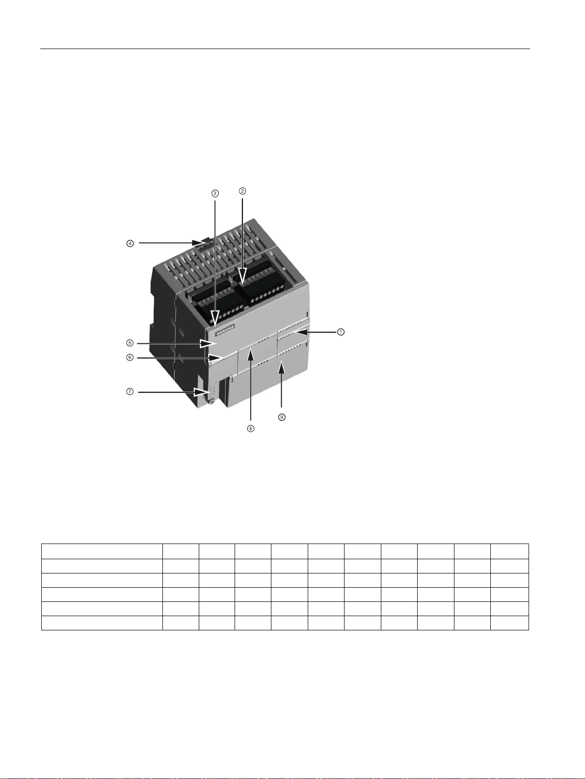
1.1
S7-200 SMART CPU
①
LEDs for the I/O
②
Terminal connectors
③
Ethernet communication
port
④
Clip for installation on a
standard (DIN) rail
⑤
Ethernet status LEDs
(under door): LINK, Rx/Tx
⑥
Status LEDs: RUN, STOP
and ERROR
⑦
RS485 Communication
port
⑧
Optional signal board
(Standard models only)
⑨
Memory card connection
(under door)
CR40
CR60
SR20
ST20
SR30
ST30
SR40
ST40
SR60
ST60
Compact, non-expandable
X X
Standard, expandable
X X X X X X X X Relay output
X X X X X X Transistor output (DC)
X X X
X
I/O points (built-in)
40
60
20
20
30
30
40
40
60
60
1.1 S7-200 SMART CPU
The CPU combines a microprocessor, an integrated power supply, input circuits, and output
circuits in a compact housing to create a powerful Micro PLC. After you have downloaded
your program, the CPU contains the logic required to monitor and control the input and
output devices in your application.
The CPU provides different models with a diversity of features and capabilities that help you
create effective solutions for your varied applications. The different models of CPUs are
shown below. For detailed information about a specific CPU, see the technical specifications
(Page 570).
Table 1- 1 S7-200 SMART CPUs
S7-200 SMART
18 System Manual, 09/2015, A5E03822230-AC

Product overview
Features
CPU CR40
CPU CR60
Dimensions: W x H x D (mm)
125 x 100 x 81
175 x 100 x 81
User data
8 Kbytes
8 Kbytes
Expansion modules
None
None
Signal board
None
None
2 at 50 K Hz A/B phase
2 at 50 K Hz A/B phase
PID loops
8 8 Real-time clock with 7-day back-up
No
No
1
ues on retentive timers) to be retentive, up to the specified maximum amount.
Features
CPU SR20, CPU
ST20
CPU SR30, CPU
ST30
CPU SR40, CPU
ST40
CPU SR60, CPU
ST60
Dimensions: W x H x D (mm)
90 x 100 x 81
110 x 100 x 81
125 x 100 x 81
175 x 100 x 81
User memory
Program
12 Kbytes
18 Kbytes
24 Kbytes
30 Kbytes
User data
8 Kbytes
12 Kbytes
16 Kbytes
20 Kbytes
Retentive
10 Kbytes max.1
10 Kbytes max.1
10 Kbytes max.1
10 Kbytes max.1
Expansion modules
6 max.
6 max.
6 max.
6 max.
Signal board
1 1 1
1
Pulse outputs 2
2 at 100 KHz
3 at 100 K Hz
3 at 100 KHz
3 at 100 KHz
PID loops
8 8 8 8 Real-time clock with 7-day back-up
Yes
Yes
Yes
Yes
1
2
is not recommended for CPU models with relay outputs.
1.1 S7-200 SMART CPU
Table 1- 2 Compact non-expandable CPUs
User memory Program 12 Kbytes 12 Kbytes
Retentive 10 Kbytes max.1 10 Kbytes max.1
On-board digital I/O
• Inputs
• Outputs
• 24 DI
• 16 DQ Relay
36 DI
24 DQ Relay
High-speed counters 4 at 100 K Hz single phase
or
4 at 100 K Hz single phase
or
You can configure areas of V memory, M memory, C memory (current values), and portions of T memory (current val-
Table 1- 3 Standard expandable CPUs
On-board digital I/O
• Inputs
• Outputs
• 12 DI
• 8 DQ
• 18 DI
• 12 DQ
• 24 DI
• 16 DQ
• 36 DI
• 24 DQ
High-speed counters 4 at 200 K Hz
single phase
or
2 at 100 K Hz A/B
phase
You can configure areas of V memory, M memory, C memory (current values), and portions of T memory (current val-
ues on retentive timers) to be retentive, up to the specified maximum amount.
The specified maximum pulse frequency is possible only for CPU models with transistor outputs. Pulse output operation
S7-200 SMART
System Manual, 09/2015, A5E03822230-AC
4 at 200 K Hz single phase
or
2 at 100 K Hz A/B
phase
4 at 200 K Hz single phase
or
2 at 100 K Hz A/B
phase
4 at 200 K Hz single phase
or
2 at 100 K Hz A/B
phase
19

Product overview
1.2
S7-200 SMART expansion modules
Type
Input only
Output only
Combination In/Out
Other
Module
Type
Description
1.2 S7-200 SMART expansion modules
Refer to the technical specifications (Page 565) for the power requirements of the CPU and
the expansion modules. Use the worksheets in Appendix B, Calculating a power budget
(Page 656) to calculate your power budget.
To better solve your application requirements, the S7-200 SMART family includes a wide
variety of expansion modules, signal boards, and a communications module. You can use
these expansion modules with the standard CPU models (SR20, ST20, SR30, ST30, SR40,
ST40, SR60 or ST60) to add additional functionality to the CPU. The following table provides
a list of the expansion modules that are currently available. For detailed information about a
specific module, see the technical specifications (Page 565).
Table 1- 4 Expansion modules and signal boards
Digital expansion module
Analog expansion modules
Signal boards
• 8 x DC In • 8 x DC Out
• 8 x Relay Out
• 4 x Analog In
• 8 x Analog In
• 2 x RTD In
• 4 x RTD In
• 4 x TC In
• 1 x Analog In • 1 x Analog Out • 2 x DC In x 2 x DC Out • RS485/RS232
• 2 x Analog Out
• 4 x Analog Out
Table 1- 5 Communication expansion modules
Communication expansion module
(EM)
PROFIBUS DP SMART module EM DP01 PROFIBUS DP
• 8 x DC In / 8 x DC Out
• 8 x DC In / 8 x Relay Out
• 16 x DC In / 16 x DC Out
• 16 x DC In / 16 x Relay Out
• 4 x Analog In / 2 x Analog Out
• 2 x Analog In / 1 x Analog Out
• Battery Board
S7-200 SMART
20 System Manual, 09/2015, A5E03822230-AC
Product overview
1.3
HMI devices for S7-200 SMART
Text Display unit:
to your application.
SMART HMIs:
1.3 HMI devices for S7-200 SMART
The S7-200 SMART supports Comfort HMIs, SMART HMIs, Basic HMIs and Micro HMIs.
The TD400C and the SMART LINE Touch Panel are shown below. Refer to Appendix C,
Human Machine Interface (Page 705) for a complete list of supported devices and article
numbers.
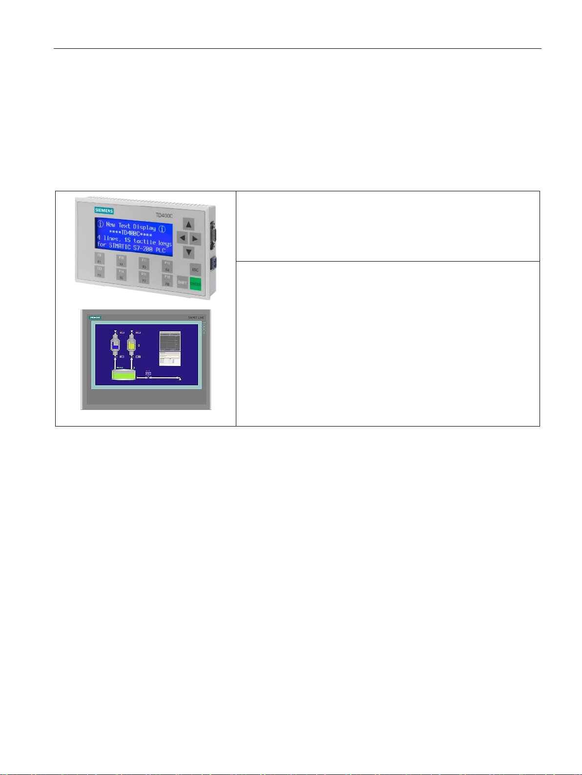
Table 1- 6 HMI devices
The TD400C is a display device that can be connected to
the CPU. Using the Text Display wizard, you can easily program your CPU
to display text messages and other data pertaining to your application.
The TD400C device provides a low cost interface to your application by
allowing you to view, monitor, and change the process variables pertaining
The SMART LINE Touch Panel provides operating and
monitoring functions for small-scale machines and plants. Short configuration and commissioning times, their configuration in WinCC flexible (ASIA
version), and a double-port Ethernet/RS485 interface form the highlights of
these HMIs.
The Text Display wizard in STEP 7-Micro/WIN SMART helps you configure Text Display
messages quickly and easily for the TD400C. To start the Text Display wizard, select the
"Text Display" command from the "Tools" menu.
The SIMATIC Text Display (TD) User Manual can be downloaded from the Siemens
customer support web site.
S7-200 SMART
System Manual, 09/2015, A5E03822230-AC
21

Product overview
1.4
Communications options
1.4 Communications options
The S7-200 SMART offers several types of communication between CPUs, programming
devices, and HMIs:
● Ethernet:
– Exchange of data from the programming device to the CPU
– Exchange of data between HMIs and the CPU
– S7 peer-to-peer communication with other S7-200 SMART CPUs
● PROFIBUS:
– High speed communications for distributed I/O (up to 12 Mbps)
– One bus master connects to many I/O devices (supports 126 addressable devices).
– Exchange of data between the master and I/O devices
– EM DP01 module is a PROFIBUS I/O device.
● RS485:
– Supports a total of 126 addressable devices (32 devices per network segment)
– Supports PPI (point-to-point interface) protocol
– Exchange of data between HMIs and the CPU
– Exchange of data between devices and the CPU using Freeport (XMT/RCV
instructions)
● RS232:
– Supports a point-to-point connection to one device
– Supports PPI protocol
– Exchange of data between HMIs and the CPU
– Exchange of data between devices and the CPU using Freeport (XMT/RCV
instructions)
S7-200 SMART
22 System Manual, 09/2015, A5E03822230-AC
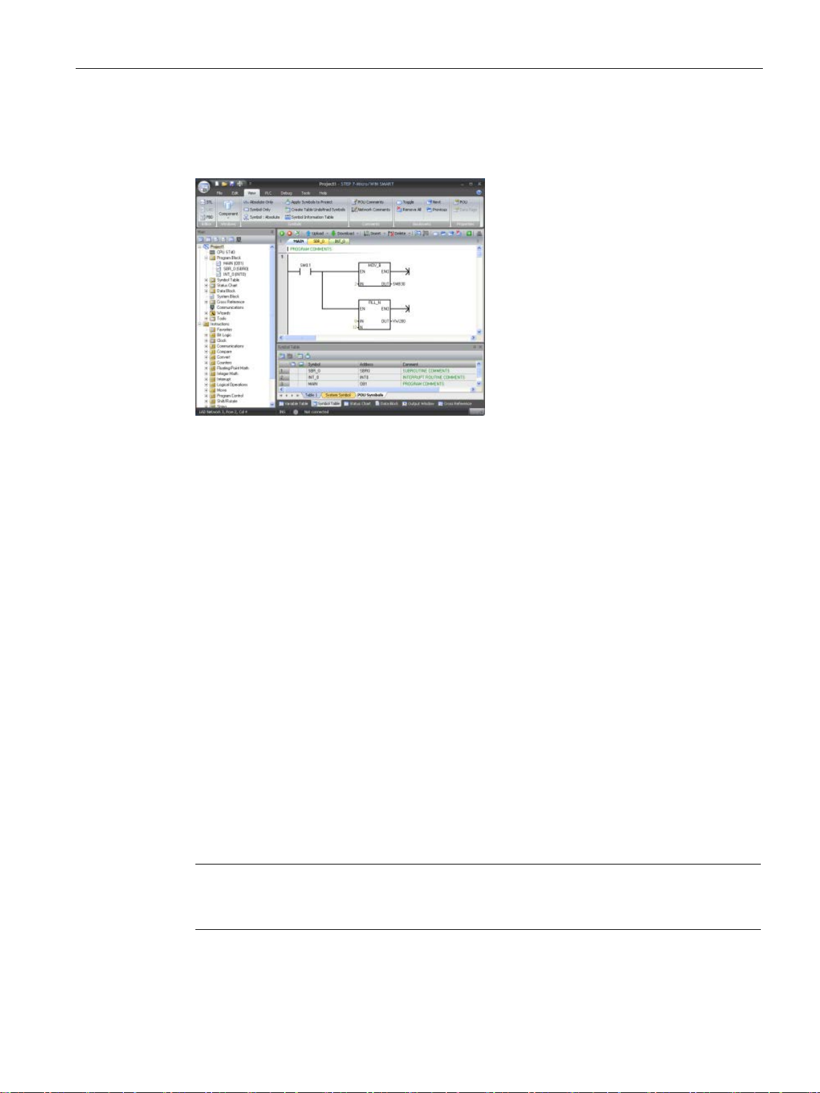
Product overview
1.5
Programming software
STEP7
SMART provides a
user
edit, and monitor the logic needed to
control your application.
At the top is a quick access toolbar for
frequent tasks, followed by menus for
all common functions. At the left is the
project tree and navigation bar for
easy access to components and i
structions. The program editor and
other components that you open o
cupy the remainder of the us
face.
STEP7
three program editors (LAD, FBD, and
STL) for convenience and efficiency in
developing the control program for
your application.
Computer requirements
Installing STEP 7-Micro/WIN SMART
Note
To install STEP
7 operating system, you
must log in with Administrator privileges.
1.5 Programming software
-Micro/WIN
-friendly environment to develop,
n-
c-
er inter-
-Micro/WIN SMART provides
To help you find the information you need, STEP7-Micro/WIN SMART provides an extensive
online help system.
STEP 7-Micro/WIN SMART runs on a personal computer. Your computer should meet the
following minimum requirements:
● Operating system: Windows XP SP3 (32 bit only), Windows 7 (both 32 bit and 64 bits
supported)
● At least 350M bytes of free hard disk space
● Mouse (recommended)
Insert the STEP 7-Micro/WIN SMART CD into the CD-ROM drive of your computer or
S7-200 SMART
System Manual, 09/2015, A5E03822230-AC
contact your Siemens distributor or sales office to download STEP7-Micro/WIN SMART from
the customer support web site (Page 3). Installation starts automatically and prompts you
through the installation process. Refer to the Readme file for more information about
installing STEP 7-Micro/WIN SMART.
7-Micro/WIN SMART on a Windows XP or Windows
23

Product overview
1.6
New features
1.6 New features
STEP 7-Micro/WIN SMART V2.1 and the S7-200 SMART V2.1 CPUs introduce the following
new features:
● New modules:
– EM DP01: intelligent expansion module that supports MPI protocol and PROFIBUS
DP V0, V1 as a slave
– EM AM03: analog expansion module with two analog inputs and one analog output
– EM AR04: analog expansion module with four RTD input channels
– EM AE08: analog expansion module with eight analog input channels
– EM AQ04: analog expansion module with four analog output channels
– SB AE01: signal board with one analog input channel
● Enhancement of the PLS instruction to work with PTO (Pulse Train Output) functions as
well as PWM (Pulse Width Modulation) functions
● Performance enhancements
S7-200 SMART
24 System Manual, 09/2015, A5E03822230-AC

2
2.1
Connecting to the CPU
Connecting power to the CPU
WARNING
Ensure power is off prior to installing, wiring or removing devices
STEP 7-Micro/WIN SMART makes it easy for you to program your CPU. In just a few short
steps using a simple example, you can learn how to create a user program that you can
download and run on your CPU.
All you need for this example is an Ethernet cable, a CPU, and a programming device
running the STEP 7-Micro/WIN SMART programming software.
Connecting your CPU is easy. For this example, you only need to connect power to your
CPU and then connect the Ethernet communication cable between your programming device
and the CPU.
Before you install or remove any electrical device, ensure that the power to that equipment
has been turned off.
Attempts to install or connect the wiring for the CPU or related equipment with power
applied could cause electric shock or faulty operation of equipment. Failure to disable all
power to the CPU and related equipment during installation or removal procedures could
result in death or serious injury to personnel, and/or damage to equipment.
Always follow appropriate safety precautions and ensure that power to the CPU is disabled
before attempting to install or remove the CPU or related equipment.
S7-200 SMART
System Manual, 09/2015, A5E03822230-AC
25
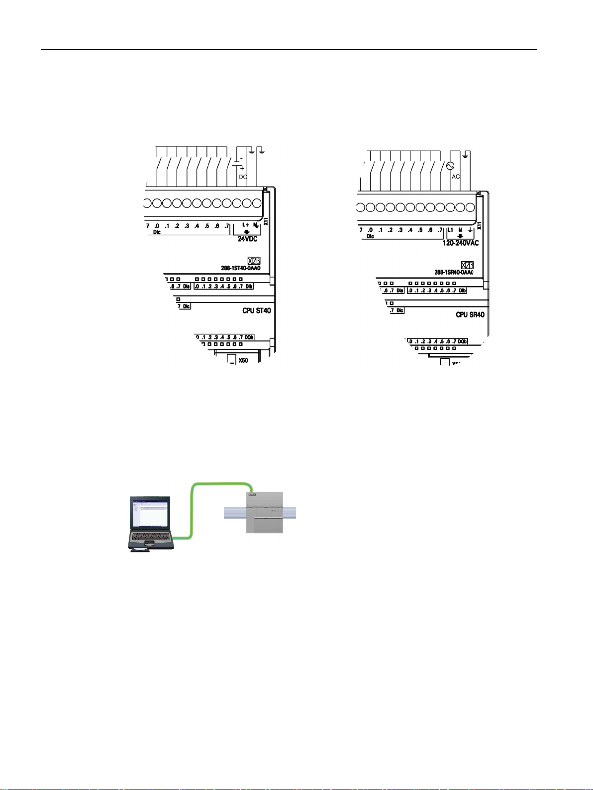
Getting started
DC installation
AC installation
2.1.1
Configuring the CPU for communication
2.1.1.1
Overview
A CPU can communicate with a
STEP
vice on an Ethernet netw
2.1 Connecting to the CPU
Connect the CPU to a power source. The following figure shows the wiring connections for
either a DC or an AC model of the CPU.
7-Micro/WIN SMART programming de-
ork.
Consider the following when setting up communications between a CPU and a programming
device:
● Configuration/Setup: No hardware configuration is required for a single CPU. If you want
multiple CPU's on the same network, then you must change the default IP addresses to
new, unique IP addresses.
● No Ethernet switch is required for one-to-one communications; an Ethernet switch is
required for more than two devices in a network.
S7-200 SMART
26 System Manual, 09/2015, A5E03822230-AC
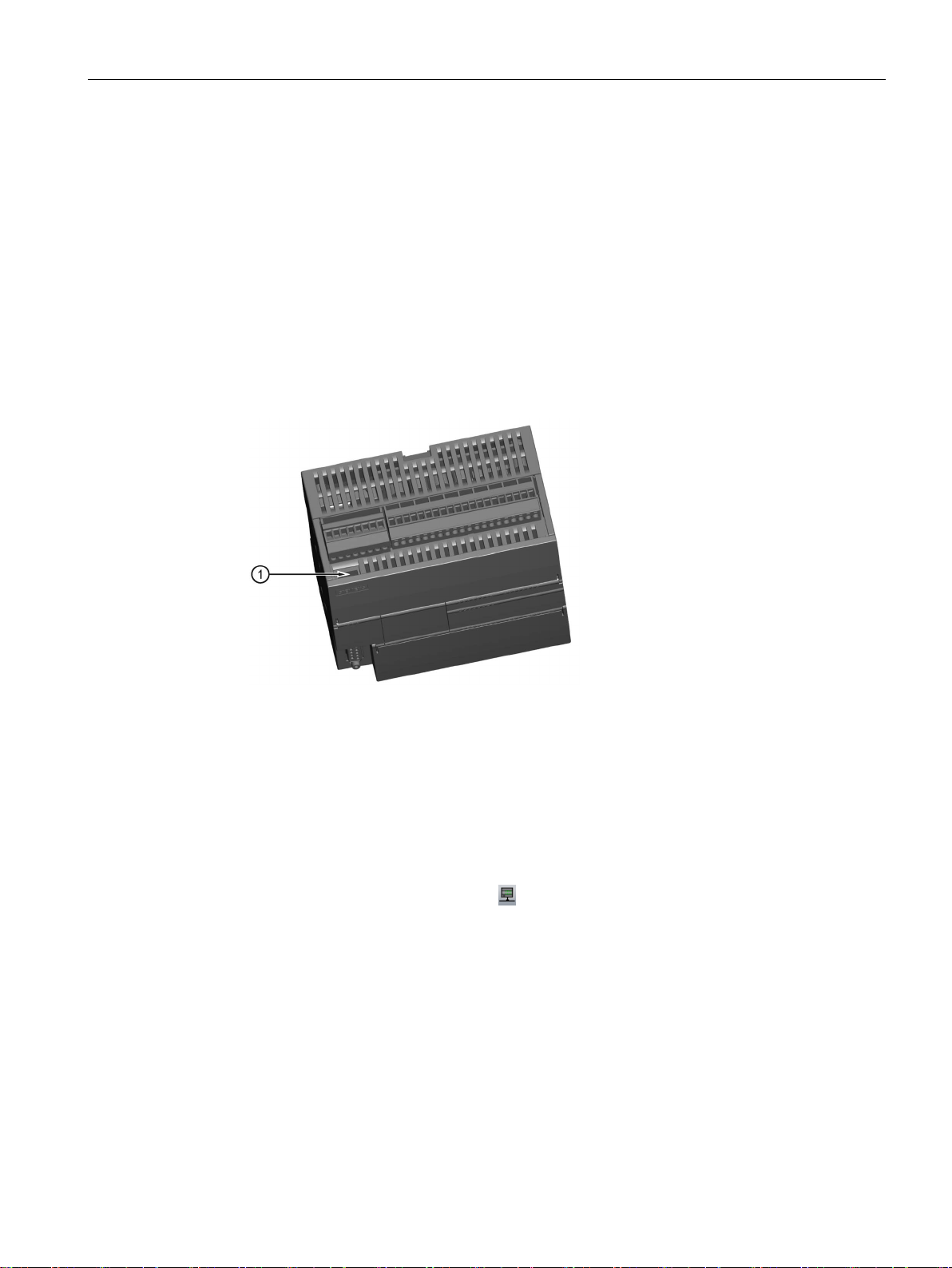
Getting started
2.1.1.2
Establishing the hardware communication connection
①
Ethernet port
2.1.1.3
Setting up communication with the CPU
2.1 Connecting to the CPU
The Ethernet interfaces establish the physical connections between a programming device
and a CPU. Since Auto-Cross-Over functionality is built into the CPU, either a standard or
crossover Ethernet cable can be used for the interface. An Ethernet switch is not required to
connect a programming device directly to a CPU.
Follow the steps below to create the hardware connection between a programming device
and a CPU:
1. Install the CPU.
2. Remove the RJ45 connection cover from the Ethernet port. Retain the cover for reuse.
3. Plug the Ethernet cable into the Ethernet port on top of the CPU as shown below.
4. Connect the Ethernet cable to the programming device.
From STEP 7-Micro/WIN SMART, use one of the following methods to display the
"Communications" dialog for configuring communication to the CPU.
● From the project tree, double-click the "Communications" node.
● Click the "Communications" button
● Select "Communications" from the Component drop-down list in the Windows area of the
View menu ribbon strip.
The "Communication" dialog provides two methods of selecting the CPU to be accessed:
● Click the "Find CPUs" button to have STEP 7-Micro/WIN SMART search your local
network for CPUs. The IP address of each CPU found on the network is listed under
"Found CPUs".
● Click the "Add CPU ..." button to manually enter the access information (IP address and
so forth) for a CPU that you wish to access. The IP address for each CPU, manually
added with this method, is listed under "Added CPUs" and is retained.
from the navigation bar.
S7-200 SMART
System Manual, 09/2015, A5E03822230-AC
27
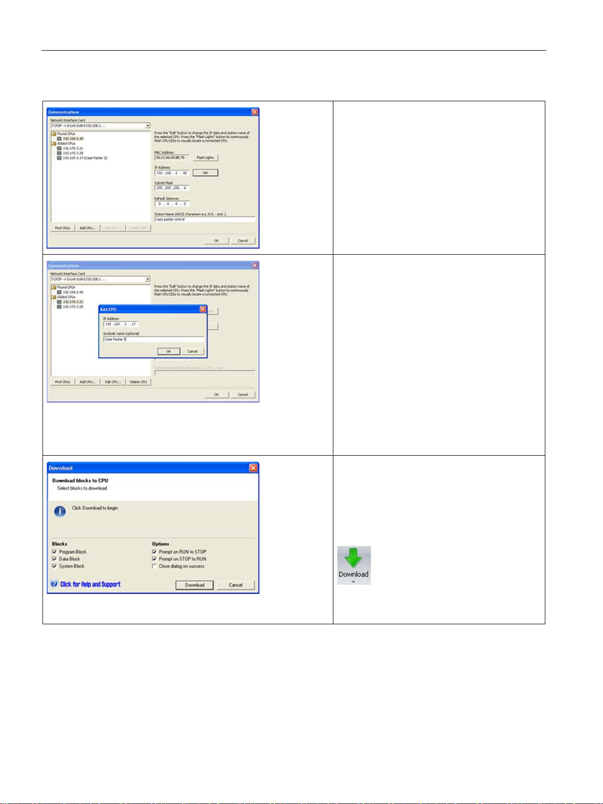
Getting started
parameters and repeat these steps.
2.1 Connecting to the CPU
For "Found CPUs" (CPUs located on your local
network), use the "Communications dialog" to
connect with your CPU:
• Select TCP/IP for your network interface card.
• Click the "Find CPUs" button to display all
operational CPUs ("Found CPUs") on the local
Ethernet network. All CPUs have a default IP
address. See the Note below.
• Highlight a CPU, and then click "OK".
For "Added CPUs" (CPUs on the local or remote
networks), use the "Communications dialog" to
connect with your CPU:
• Select TCP/IP for your network interface card.
• Click the "Add CPU" button to do one of the
following:
– Enter the IP address of a CPU that is ac-
cessible from the programming device, but
is not on the local network.
– Enter the IP address of a CPU directly that
is on the local network.
All CPUs have a default IP address. See the
Note below.
• Highlight a CPU, and then click "OK".
After you have established communication with
the CPU, you are ready to create and download
the example program.
To download all project components, click the
Download button from the Transfer area of the File
or PLC menu ribbon strip, or alternatively press
the shortcut key combination CTRL+D.
S7-200 SMART
If STEP 7-Micro/WIN SMART does not find your
CPU, check the settings for the communications
28 System Manual, 09/2015, A5E03822230-AC
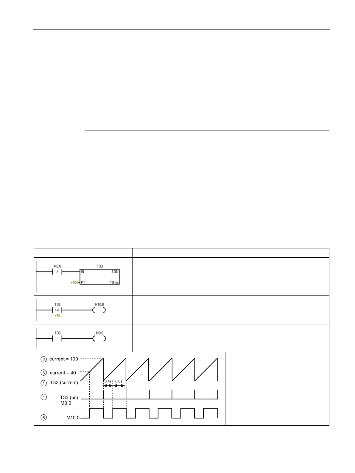
Getting started
Note
The CPU list will show all of the CPUs regardless of Ethernet network class and subnet.
To make a connection to your CPU, your network interface card (NIC) and the CPU must be
on the same class of network and on the same subnet. You can either set up your network
interface card to match the default IP address of the CPU, or you can change the IP address
of the CPU to match the network class and subnet of your network interface card.
See the "Configuring or changing an IP address for a CPU or device in your project" for
information about how to accomplish this.
2.2
Creating the sample program
LAD/FBD
STL
Description
Network 1
LDN M0.0
TON T33, +100
Network 2
LDW>= T33, +40
= M10.0
Network 3
LD T33
= M0.0
Timing diagram:
2.2 Creating the sample program
Entering this example of a control program will help you understand how easy it is to use
STEP 7-Micro/WIN SMART. This program uses six instructions in three networks to create a
very simple, self-starting timer that resets itself.
For this example, you use the Ladder (LAD) editor to enter the instructions for the program.
The following example shows the complete program in both LAD and Statement List (STL).
The description column explains the logic for each network. The timing diagram shows the
operation of the program. There are no network comments in the STL program.
Table 2- 1 Sample program for getting started with STEP 7-Micro/WIN SMART
10 ms timer T33 times out after (100 x 10 ms = 1 s)
M0.0 pulse is too fast to monitor with Status view.
Comparison becomes true at a rate that is visible
with Status view. Turn on M10.0 after (40 x 10 ms =
0.4 s) for a 40% OFF / 60% ON waveform.
T33 (bit) pulse is too fast to monitor with Status view.
Reset the timer through M0.0 after the (100 x 10 ms
= 1 s) period.
• ① T33 (current)
② Current = 100
•
③ Current = 40
•
④ T33 (bit) and M0.0
•
⑤ M10.0
•
S7-200 SMART
System Manual, 09/2015, A5E03822230-AC
29
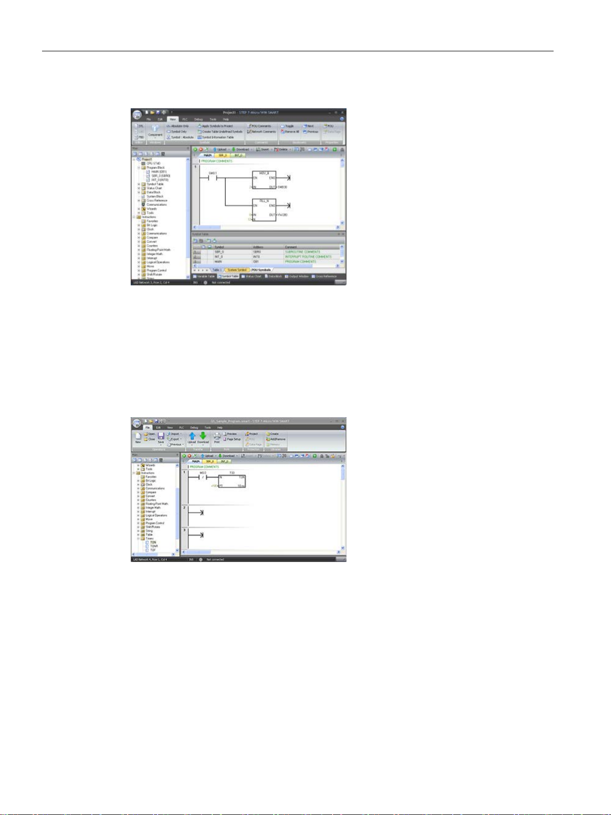
Getting started
Notice the project tree and the pr
gram editor. You use the project tree
to insert instructions into the networks
of the program editor by dragging and
dropping the instructions from the
"Instructions" portion of the Proj
tree to the networks.
The Program Block folder in the pr
ject tree contains all of the blocks of
your program.
The program editor toolbar icons pr
vide shortcuts to PLC commands and
programming operation.
2.2.1
Network 1: Starting the timer
Network 1: Starting the timer
When M0.0 is off (0), this contact turns
on and provides power flow to start
the timer.
2.2 Creating the sample program
o-
ect
o-
o-
After you enter and save the program, you can download the program to the CPU.
To enter the contact for M0.0:
1. Either double-click the "Bit Logic" icon or click the plus sign (+) to display the bit logic
instructions.
S7-200 SMART
30 System Manual, 09/2015, A5E03822230-AC
2. Select the "Normally Closed" contact.
3. Hold down the left mouse button and drag the contact onto the first network.
4. Enter the following address for the contact: M0.0
5. Press the Return key to enter the address for the contact.
 Loading...