

Siemens SIMATIC S7, SIMATIC S7-200 SMART System Manual

___________________
___________________
___________________
___________________
___________________
___________________
___________________
___________________
___________________
___________________
___________________
___________________
___________________
___________________
___________________
___________________
___________________
___________________
___________________
SIMATIC
S7
S7-200 SMART
System Manual
V2.3, 07/2017
A5E03822230
Preface
Product overview
1
Getting started
2
Installation
3
PLC concepts
4
Programming concepts
5
PLC device configuration
6
Program instructions
7
Communication
8
Libraries
9
Debugging and
troubleshooting
10
PID loops and tuning
11
Open loop motion control
12
Technical specifications
A
Calculating a power budget
B
Error codes
C
Special memory (SM) and
system symbol names
D
References
E
Ordering information
F
-AF
Siemens AG
Division Digital Factory
Postfach 48 48
90026 NÜRNBERG
GERMANY
A5E03822230-AF
Ⓟ
Copyright © Siemens AG 2017.
All rights reserved
Legal information
Warning notice system
DANGER
indicates that death or severe personal injury will result if proper precautions are not taken.
WARNING
indicates that death or severe personal injury may result if proper precautions are not taken.
CAUTION
indicates that minor personal injury can result if proper precautions are not taken.
NOTICE
indicates that property damage can result if proper precautions are not taken.
Qualified Personnel
personnel qualified
Proper use of Siemens products
WARNING
Siemens products may only be used for the applications described in the catalog and in the relevant technical
maintenance are required to ensure that the products operate safely and without any problems. The permissible
ambient conditions must be complied with. The information in the relevant documentation must be observed.
Trademarks
Disclaimer of Liability
This manual contains notices you have to observe in order to ensure your personal safety, as well as to prevent
damage to property. The notices referring to your personal safety are highlighted in the manual by a safety alert
symbol, notices referring only to property damage have no safety alert symbol. These notices shown below are
graded according to the degree of danger.
If more than one degree of danger is present, the warning notice representing the highest degree of danger will
be used. A notice warning of injury to persons with a safety alert symbol may also include a warning relating to
property damage.
The product/system described in this documentation may be operated only by
task in accordance with the relevant documentation, in particular its warning notices and safety instructions.
Qualified personnel are those who, based on their training and experience, are capable of identifying risks and
avoiding potential hazards when working with these products/systems.
Note the following:
documentation. If products and components from other manufacturers are used, these must be recommended
or approved by Siemens. Proper transport, storage, installation, assembly, commissioning, operation and
All names identified by ® are registered trademarks of Siemens AG. The remaining trademarks in this publication
may be trademarks whose use by third parties for their own purposes could violate the rights of the owner.
We have reviewed the contents of this publication to ensure consistency with the hardware and software
described. Since variance cannot be precluded entirely, we cannot guarantee full consistency. However, the
information in this publication is reviewed regularly and any necessary corrections are included in subsequent
editions.
for the specific
06/2017 Subject to change

Preface
Purpose of the manual
Required basic knowledge
Scope of the manual
Certification, CE label and other standards
Service and support
The S7-200 SMART series is a line of micro-programmable logic controllers (Micro PLCs)
that can control a variety of automation applications. Compact design, low cost, and a
powerful instruction set make the S7-200 SMART a perfect solution for controlling small
applications. The wide variety of S7-200 SMART models and the Windows-based
programming tool give you the flexibility you need to solve your automation problems.
This manual provides information about installing and programming the S7-200 SMART
CPUs and is designed for engineers, programmers, installers, and electricians who have a
general knowledge of programmable logic controllers.
To understand this manual, it is necessary to have a general knowledge of automation and
programmable logic controllers.
This manual describes the following products:
● STEP 7-Micro/WIN SMART V2.3
● S7-200 SMART CPU firmware release V2.3
For a complete list of the S7-200 SMART products and article numbers described in this
manual, see Technical Specifications (Page 679).
Refer to the technical specifications for more information.
In addition to our documentation, we offer our technical expertise on the Internet on the
customer support web site (http://www.siemens.com/automation/).
Contact your Siemens distributor or sales office for assistance in answering any technical
questions, for training, or for ordering S7 products. Because your sales representatives are
technically trained and have the most specific knowledge about your operations, process
and industry, as well as about the individual Siemens products that you are using, they can
provide the fastest and most efficient answers to any problems you might encounter.
S7-200 SMART
System Manual, V2.3, 07/2017, A5E03822230-AF
3

Preface
Security information
Siemens provides products and solutions with industrial security functions that support the
secure operation of plants, systems, machines and networks.
In order to protect plants, systems, machines and networks against cyber threats, it is
necessary to implement – and continuously maintain – a holistic, state-of-the-art industrial
security concept. Siemens’ products and solutions only form one element of such a concept.
Customer is responsible to prevent unauthorized access to its plants, systems, machines
and networks. Systems, machines and components should only be connected to the
enterprise network or the internet if and to the extent necessary and with appropriate security
measures (e.g. use of firewalls and network segmentation) in place.
Additionally, Siemens’ guidance on appropriate security measures should be taken into
account. For more information about industrial security, please visit
(http://www.siemens.com/industrialsecurity).
Siemens’ products and solutions undergo continuous development to make them more
secure. Siemens strongly recommends to apply product updates as soon as available and to
always use the latest product versions. Use of product versions that are no longer supported,
and failure to apply latest updates may increase customer’s exposure to cyber threats.
To stay informed about product updates, subscribe to the Siemens Industrial Security RSS
Feed under (http://www.siemens.com/industrialsecurity).
S7-200 SMART
4 System Manual, V2.3, 07/2017, A5E03822230-AF

Table of contents
Preface ................................................................................................................................................... 3
1 Product overview .................................................................................................................................. 17
2 Getting started ...................................................................................................................................... 31
3 Installation ............................................................................................................................................ 47
1.1 S7-200 SMART CPU .............................................................................................................. 18
1.2 New features ........................................................................................................................... 21
1.3 CPU feature differences.......................................................................................................... 23
1.4 S7-200 SMART expansion modules ....................................................................................... 26
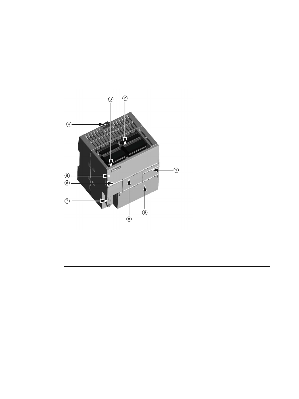
1.5 HMI devices for S7-200 SMART ............................................................................................. 27
1.6 Communications options ........................................................................................................ 28
1.7 Programming software ............................................................................................................ 29
2.1 Connecting to the CPU ........................................................................................................... 31
2.1.1 Configuring the CPU for communication ................................................................................ 32
2.1.1.1 Overview ................................................................................................................................. 32
2.1.1.2 Establishing the Ethernet hardware communication connection ............................................ 33
2.1.1.3 Setting up Ethernet communication with the CPU .................................................................. 34
2.1.1.4 Establishing the RS485 hardware communication connection............................................... 36
2.1.1.5 Setting up RS485 communication with the CPU .................................................................... 37
2.2 Creating the sample program ................................................................................................. 39
2.2.1 Network 1: Starting the timer .................................................................................................. 40
2.2.2 Network 2: Turning the output on ........................................................................................... 41
2.2.3 Network 3: Resetting the timer ............................................................................................... 42
2.2.4 Setting the CPU type and version for your project ................................................................. 43
2.2.5 Saving the sample project ...................................................................................................... 44
2.3 Downloading the sample program .......................................................................................... 45
2.4 Changing the operating mode of the CPU .............................................................................. 46
3.1 Guidelines for installing S7-200 SMART devices ................................................................... 47
3.2 Power budget .......................................................................................................................... 49
3.3 Installation and removal procedures ....................................................................................... 51
3.3.1 Mounting dimensions for the S7-200 SMART devices ........................................................... 51
3.3.2 Installing and removing the CPU ............................................................................................ 52
3.3.3 Installing and removing a signal board or battery board ......................................................... 55
3.3.4 Removing and reinstalling the terminal block connector ........................................................ 57
3.3.5 Installing and removing an expansion module ....................................................................... 58
3.3.6 Installing and removing the expansion cable .......................................................................... 60
3.4 Wiring guidelines ..................................................................................................................... 62
S7-200 SMART
System Manual, V2.3, 07/2017, A5E03822230-AF
5

Table of contents
4 PLC concepts ....................................................................................................................................... 69
5 Programming concepts ........................................................................................................................ 103
4.1 Execution of the control logic ................................................................................................. 69
4.1.1 Reading the inputs and writing to the outputs ........................................................................ 71
4.1.2 Immediately reading or writing the I/O ................................................................................... 71
4.1.3 Executing the user program ................................................................................................... 72
4.2 Accessing data ....................................................................................................................... 74
4.2.1 Accessing memory areas ....................................................................................................... 75
4.2.2 Format for Real numbers ....................................................................................................... 82
4.2.3 Format for strings ................................................................................................................... 82
4.2.4 Assigning a constant value for instructions ............................................................................ 83
4.2.5 Addressing the local and expansion I/O ................................................................................ 83
4.2.6 Using pointers for indirect addressing.................................................................................... 84
4.2.7 Pointer examples ................................................................................................................... 87
4.3 Saving and restoring data ...................................................................................................... 89
4.3.1 Downloading project components .......................................................................................... 89
4.3.2 Uploading project components .............................................................................................. 92
4.3.3 Types of storage .................................................................................................................... 93
4.3.4 Using a memory card ............................................................................................................. 94
4.3.5 Inserting a memory card in a standard CPU .......................................................................... 96
4.3.6 Transferring your program with a memory card ..................................................................... 97
4.3.7 Restoring data after power on ................................................................................................ 99
4.4 Changing the operating mode of the CPU ........................................................................... 100
4.5 Status LEDs ......................................................................................................................... 101
5.1 Guidelines for designing a PLC system ............................................................................... 103
5.2 Elements of the user program .............................................................................................. 105
5.3 Creating your user program ................................................................................................. 108
5.3.1 Earlier versions of STEP 7-Micro/WIN projects ................................................................... 108
5.3.2 Using STEP 7-Micro/WIN SMART user interface ................................................................ 110
5.3.3 Using STEP 7-Micro/WIN SMART to create your programs ............................................... 111
5.3.4 Using wizards to help you create your control program....................................................... 112
5.3.5 Features of the LAD editor ................................................................................................... 113
5.3.6 Features of the FBD editor ................................................................................................... 114
5.3.7 Features of the STL editor ................................................................................................... 114
5.4 Data block (DB) editor .......................................................................................................... 115
5.5 Symbol table ........................................................................................................................ 118
5.6 Variable table ....................................................................................................................... 121
5.7 PLC error reaction ................................................................................................................ 127
5.7.1 Non-fatal errors and I/O errors ............................................................................................. 128
5.7.2 Fatal errors ........................................................................................................................... 129
5.8 Program edit in RUN mode .................................................................................................. 130
5.9 Features for debugging your program ................................................................................. 132
S7-200 SMART
6 System Manual, V2.3, 07/2017, A5E03822230-AF

Table of contents
6 PLC device configuration .................................................................................................................... 133
7 Program instructions ........................................................................................................................... 169
6.1 Configuring the operation of the PLC system ....................................................................... 133
6.1.1 System block ......................................................................................................................... 133
6.1.2 Configuring communication .................................................................................................. 135
6.1.3 Configuring the digital inputs ................................................................................................ 138
6.1.4 Configuring the digital outputs .............................................................................................. 140
6.1.5 Configuring the retentive ranges ........................................................................................... 141
6.1.6 Configuring system security .................................................................................................. 143
6.1.7 Configuring the startup options ............................................................................................. 147
6.1.8 Configuring the analog inputs ............................................................................................... 148
6.1.9 Reference to the analog inputs technical specifications ....................................................... 150
6.1.10 Configuring the analog outputs ............................................................................................. 151
6.1.11 Reference to the analog outputs technical specifications..................................................... 152
6.1.12 Configuring the RTD analog inputs ....................................................................................... 153
6.1.13 Configuring the TC analog inputs ......................................................................................... 158
6.1.14 Configuring the RS485/RS232 CM01 communications signal board ................................... 162
6.1.15 Configuring the BA01 battery signal board ........................................................................... 163
6.1.16 Clearing PLC memory........................................................................................................... 164
6.1.17 Creating a reset-to-factory-defaults memory card ................................................................ 167
6.2 High-speed I/O ...................................................................................................................... 168
7.1 Bit logic ................................................................................................................................. 169
7.1.1 Standard inputs ..................................................................................................................... 169
7.1.2 Immediate inputs ................................................................................................................... 171
7.1.3 Logic stack overview ............................................................................................................. 172
7.1.4 STL logic stack instructions .................................................................................................. 174
7.1.5 NOT....................................................................................................................................... 176
7.1.6 Positive and negative transition detectors ............................................................................ 177
7.1.7 Coils: output and output immediate instructions ................................................................... 178
7.1.8 Set, reset, set immediate, and reset immediate functions .................................................... 179
7.1.9 Set and reset dominant bistable ........................................................................................... 180
7.1.10 NOP (No operation) instruction ............................................................................................. 181
7.1.11 Bit logic input examples ........................................................................................................ 182
7.1.12 Bit logic output examples ...................................................................................................... 183
7.2 Clock ..................................................................................................................................... 185
7.2.1 Read and set real-time clock ................................................................................................ 185
7.2.2 Read and set real-time clock extended ................................................................................ 187
7.3 Communication ..................................................................................................................... 191
7.3.1 GET and PUT (Ethernet) ...................................................................................................... 191
7.3.2 Transmit and receive (Freeport on RS485/RS232) .............................................................. 199
7.3.3 Get port address and set port address (PPI protocol on RS485/RS232) ............................. 213
7.3.4 Get IP address and set IP address (Ethernet) ...................................................................... 214
7.3.5 Open user communication .................................................................................................... 217
7.3.5.1 OUC instructions ................................................................................................................... 217
7.3.5.2 OUC instruction error codes ................................................................................................. 228
7.4 Compare ............................................................................................................................... 230
7.4.1 Compare number values ...................................................................................................... 230
7.4.2 Compare character strings ................................................................................................... 234
S7-200 SMART
System Manual, V2.3, 07/2017, A5E03822230-AF
7

Table of contents
7.5 Convert ................................................................................................................................. 236
7.5.1 Standard conversion instructions ......................................................................................... 236
7.5.2 ASCII character array conversion ........................................................................................ 240
7.5.3 Number value to ASCII string conversion ............................................................................ 245
7.5.4 ASCII sub-string to number value conversion ..................................................................... 249
7.5.5 Encode and decode ............................................................................................................. 252
7.6 Counters ............................................................................................................................... 253
7.6.1 Counter instructions ............................................................................................................. 253
7.6.2 High-speed counter instructions .......................................................................................... 257
7.6.3 High-speed counter summary .............................................................................................. 260
7.6.4 Noise reduction for high-speed inputs ................................................................................. 261
7.6.5 High-speed counter programming ....................................................................................... 264
7.6.6 Example initialization sequences for high-speed counters .................................................. 277
7.7 Pulse output ......................................................................................................................... 285
7.7.1 Pulse output instruction (PLS) ............................................................................................. 285
7.7.2 Pulse train output (PTO) ...................................................................................................... 287
7.7.3 Pulse width modulation (PWM) ............................................................................................ 289
7.7.4 Using SM locations to configure and control the PTO/PWM operation ............................... 290
7.7.5 Calculating the profile table values ...................................................................................... 294
7.8 Math ..................................................................................................................................... 297
7.8.1 Add, subtract, multiply, and divide ....................................................................................... 297
7.8.2 Multiply integer to double integer and divide integer with remainder................................... 300
7.8.3 Trigonometry, natural logarithm/exponential, and square root ............................................ 302
7.8.4 Increment and decrement .................................................................................................... 305
7.9 PID ....................................................................................................................................... 307
7.9.1 Using the PID wizard ........................................................................................................... 308
7.9.2 PID algorithm ....................................................................................................................... 313
7.9.3 Converting and normalizing the loop inputs ......................................................................... 317
7.9.4 Converting the loop output to a scaled integer value........................................................... 318
7.9.5 Forward- or reverse-acting loops ......................................................................................... 319
7.10 Interrupt ................................................................................................................................ 322
7.10.1 Interrupt instructions ............................................................................................................ 322
7.10.2 Interrupt routine overview and CPU model event support ................................................... 324
7.10.3 Interrupt programming guidelines ........................................................................................ 326
7.10.4 Types of interrupt events that the S7-200 SMART CPU supports ...................................... 328
7.10.5
Interrupt priority, queuing, and example program ................................................................ 330
7.11 Logical operations ................................................................................................................ 335
7.11.1 Invert .................................................................................................................................... 335
7.11.2 AND, OR, and exclusive OR ................................................................................................ 336
7.12 Move .................................................................................................................................... 338
7.12.1 Move byte, word, double word, or real ................................................................................. 338
7.12.2 Block move ........................................................................................................................... 339
7.12.3 Swap bytes ........................................................................................................................... 340
7.12.4 Move byte immediate (read and write) ................................................................................ 341
7.13 Program control.................................................................................................................... 342
7.13.1 FOR-NEXT loop ................................................................................................................... 342
7.13.2 JMP (jump to label) .............................................................................................................. 344
7.13.3 SCR (sequence control relay) .............................................................................................. 345
S7-200 SMART
8 System Manual, V2.3, 07/2017, A5E03822230-AF

Table of contents
8 Communication ................................................................................................................................... 395
7.13.4 END, STOP, and WDR (watchdog timer reset) .................................................................... 354
7.13.5 GET_ERROR (Get non-fatal error code) .............................................................................. 356
7.14 Shift and rotate ...................................................................................................................... 357
7.14.1 Shift and rotate ...................................................................................................................... 357
7.14.2 Shift register bit ..................................................................................................................... 360
7.15 String ..................................................................................................................................... 362
7.15.1 String (Get length, copy, and concatenate) .......................................................................... 362
7.15.2 Copy substring from string .................................................................................................... 364
7.15.3 Find string and first character within string ........................................................................... 365
7.16 Table ..................................................................................................................................... 368
7.16.1 Add to table ........................................................................................................................... 368
7.16.2 First-in-first-out and last-in-first-out ....................................................................................... 370
7.16.3 Memory fill ............................................................................................................................. 372
7.16.4 Table find .............................................................................................................................. 373
7.17 Timer ..................................................................................................................................... 377
7.17.1 Timer instructions .................................................................................................................. 377
7.17.2 Timer programming tips and examples ................................................................................ 380
7.17.3 Interval timers ....................................................................................................................... 386
7.18 Subroutine ............................................................................................................................. 388
7.18.1 CALL (subroutine) and RET (conditional return) .................................................................. 388
8.1 CPU communication connections ......................................................................................... 396
8.2 CPU communication ports .................................................................................................... 397
8.3 HMIs and communication drivers ......................................................................................... 398
8.4 Ethernet ................................................................................................................................ 400
8.4.1 Overview ............................................................................................................................... 400
8.4.2 Local/partner connection ...................................................................................................... 400
8.4.3 Sample Ethernet network configurations .............................................................................. 401
8.4.4 Assigning Internet Protocol (IP) addresses .......................................................................... 402
8.4.4.1 Assigning IP addresses to programming and network devices ............................................ 402
8.4.4.2 Configuring or changing an IP address for a CPU or device in your project ........................ 404
8.4.4.3 Searching for CPUs and devices on your Ethernet network ................................................ 412
8.4.5 Locating the Ethernet (MAC) address on the CPU ............................................................... 413
8.4.6 HMI-to-CPU communication ................................................................................................. 415
8.4.7 Open user communication .................................................................................................... 417
8.4.7.1 Protocols ............................................................................................................................... 417
8.4.7.2 Connections .......................................................................................................................... 418
8.4.7.3 Ports and TSAPs .................................................................................................................. 419
8.5 PROFIBUS ............................................................................................................................ 421
8.5.1 EM DP01 PROFIBUS DP module ........................................................................................ 423
8.5.1.1 Distributed Peripheral (DP) standard communications ......................................................... 423
8.5.1.2 Using the EM DP01 to connect an S7-200 SMART as a DP device .................................... 424
8.5.1.3 Configuring the EM DP01 ..................................................................................................... 426
8.5.1.4 Data consistency ................................................................................................................... 427
8.5.1.5 Supported configurations ...................................................................................................... 428
8.5.1.6 Installing the EM DP01 GSD file ........................................................................................... 429
8.5.1.7 Configuring the EM DP01 I/O ............................................................................................... 431
S7-200 SMART
System Manual, V2.3, 07/2017, A5E03822230-AF
9

Table of contents
9 Libraries ............................................................................................................................................... 471
8.5.1.8 Example of V memory and I/O address area ....................................................................... 433
8.5.1.9 User program considerations ............................................................................................... 435
8.5.1.10 LED status indicators for the EM DP01 PROFIBUS DP ...................................................... 437
8.5.1.11 Using HMIs and S7-CPUs with the EM DP01 ..................................................................... 439
8.5.1.12 Device database file: GSD ................................................................................................... 440
8.5.1.13 PROFIBUS DP communications to a CPU example program ............................................. 444
8.5.1.14 Reference to the EM DP01 PROFIBUS DP module technical specifications ..................... 446
8.6 RS485 .................................................................................................................................. 446
8.6.1 PPI protocol .......................................................................................................................... 447
8.6.2 Baud rate and network address ........................................................................................... 448
8.6.2.1 Definition of baud rate and network address ....................................................................... 448
8.6.2.2 Setting the baud rate and network address for the S7-200 SMART CPU ........................... 449
8.6.3 Sample RS485 network configurations ................................................................................ 451
8.6.3.1 Single-master PPI networks ................................................................................................. 451
8.6.3.2 Multi-master and multi-slave PPI networks .......................................................................... 451
8.6.4 Assigning RS485 addresses ................................................................................................ 452
8.6.4.1 Configuring or changing an RS485 address for a CPU or device in your project ............... 452
8.6.4.2 Searching for CPUs and devices on your RS485 network .................................................. 457
8.6.5 Building your network ........................................................................................................... 458
8.6.5.1 General guidelines ............................................................................................................... 458
8.6.5.2 Determining the distances, transmission rates, and cable lengths for your network ........... 459
8.6.5.3 Repeaters on the network .................................................................................................... 459
8.6.5.4 Specifications for RS485 cable ............................................................................................ 460
8.6.5.5 Connector pin assignments ................................................................................................. 460
8.6.5.6 Biasing and terminating the network cable .......................................................................... 462
8.6.5.7 Biasing and terminating the CM01 signal board .................................................................. 463
8.6.5.8 Using HMI devices on your RS485 network ........................................................................ 464
8.6.6 Freeport mode...................................................................................................................... 465
8.6.6.1 Creating user-defined protocols with Freeport mode........................................................... 465
8.6.6.2 Using the RS232/PPI Multi-Master cable and Freeport mode with RS232 devices ............ 468
8.7 RS232 .................................................................................................................................. 470
9.1 Library types (Siemens and user-defined) ........................................................................... 471
9.2 Overview of Modbus communication ................................................................................... 473
9.2.1 Modbus addressing .............................................................................................................. 473
9.2.2 Modbus read and write functions ......................................................................................... 475
9.3 Modbus RTU library ............................................................................................................. 476
9.3.1 Modbus communication overview ........................................................................................ 476
9.3.1.1 Modbus RTU library features ............................................................................................... 476
9.3.1.2 Requirements for using Modbus instructions ....................................................................... 477
9.3.1.3 Initialization and execution time for Modbus protocol .......................................................... 478
9.3.2 Modbus RTU master ............................................................................................................ 479
9.3.2.1 Using the Modbus RTU master instructions ........................................................................ 479
9.3.2.2 MBUS_CTRL / MB_CTRL2 instruction (initialize master) .................................................... 481
9.3.2.3 MBUS_MSG / MB_MSG2 instruction ................................................................................... 483
9.3.2.4 Modbus RTU master execution error codes ........................................................................ 487
9.3.3 Modbus RTU slave .............................................................................................................. 489
9.3.3.1 Using the Modbus RTU slave instructions ........................................................................... 489
9.3.3.2 MBUS_INIT instruction (initialize slave) ............................................................................... 491
S7-200 SMART
10 System Manual, V2.3, 07/2017, A5E03822230-AF

Table of contents
10 Debugging and troubleshooting ........................................................................................................... 565
9.3.3.3 MBUS_SLAVE instruction ..................................................................................................... 492
9.3.3.4 Modbus RTU slave execution error codes............................................................................ 493
9.3.4 Modbus RTU master example program................................................................................ 494
9.3.5 Modbus RTU advanced user information ............................................................................. 496
9.4 Open user communication library ......................................................................................... 498
9.4.1 Parameters common to the OUC library instructions ........................................................... 499
9.4.2 Open user communication library instructions ...................................................................... 501
9.4.2.1 TCP_CONNECT instruction .................................................................................................. 501
9.4.2.2 ISO_CONNECT instruction ................................................................................................... 504
9.4.2.3 UDP_CONNECT instruction ................................................................................................. 508
9.4.2.4 TCP_SEND instruction.......................................................................................................... 510
9.4.2.5 TCP_RECV instruction.......................................................................................................... 513
9.4.2.6 UDP_SEND instruction ......................................................................................................... 516
9.4.2.7 UDP_RECV instruction ......................................................................................................... 519
9.4.2.8 DISCONNECT instruction ..................................................................................................... 522
9.4.3 Open user communication library instruction error codes .................................................... 524
9.4.4 Open user communication library example .......................................................................... 525
9.4.4.1 Active partner (client) ............................................................................................................ 526
9.4.4.2 CheckErrors subroutine ........................................................................................................ 535
9.4.4.3 Active partner symbol table .................................................................................................. 536
9.4.4.4 Passive partner (server)........................................................................................................ 537
9.4.4.5 CheckErrors subroutine ........................................................................................................ 543
9.4.4.6 Passive partner symbol table ................................................................................................ 544
9.5 USS library ............................................................................................................................ 545
9.5.1 USS communication overview .............................................................................................. 545
9.5.1.1 USS protocol overview.......................................................................................................... 545
9.5.1.2 Requirements for using the USS protocol ............................................................................ 546
9.5.1.3 Calculating the time required for communicating with the drive ........................................... 547
9.5.2 USS program instructions ..................................................................................................... 548
9.5.2.1 Using the USS protocol instructions ..................................................................................... 548
9.5.2.2 USS_INIT instruction ............................................................................................................. 549
9.5.2.3 USS_CTRL instruction .......................................................................................................... 551
9.5.2.4 USS_RPM_x instruction ........................................................................................................ 554
9.5.2.5 USS_WPM_x instruction ....................................................................................................... 557
9.5.2.6 USS protocol execution error codes ..................................................................................... 560
9.5.2.7 USS protocol example program ............................................................................................ 561
9.6 Creating a user-defined library of instructions ................................................................
...... 563
10.1 Debugging your program ...................................................................................................... 565
10.1.1 Bookmark functions .............................................................................................................. 565
10.1.2 Cross reference table............................................................................................................ 566
10.2 Displaying program status .................................................................................................... 568
10.2.1 Displaying status in the program editor ................................................................................ 568
10.2.2 Configuring the STL status options ....................................................................................... 571
10.3 Using a status chart to monitor your program ...................................................................... 572
10.4 Forcing specific values.......................................................................................................... 574
10.5 Writing and forcing outputs in STOP mode .......................................................................... 575
S7-200 SMART
System Manual, V2.3, 07/2017, A5E03822230-AF
11

Table of contents
11 PID loops and tuning ............................................................................................................................ 581
12 Open loop motion control ..................................................................................................................... 595
10.6 How to execute a limited number of scans .......................................................................... 576
10.7 Hardware troubleshooting guide .......................................................................................... 578
11.1 PID loop definition table ....................................................................................................... 582
11.2 Prerequisites ........................................................................................................................ 586
11.3 Auto-hysteresis and auto-deviation...................................................................................... 586
11.4 Auto-tune sequence ............................................................................................................. 587
11.5 Exception conditions ............................................................................................................ 589
11.6 Notes concerning PV out-of-range (result code 3) .............................................................. 590
11.7 PID Tune control panel ........................................................................................................ 590
12.1 Using the PWM output ......................................................................................................... 596
12.1.1 Configuring the PWM output ................................................................................................ 596
12.1.2 PWMx_RUN subroutine ....................................................................................................... 598
12.2 Using motion control ............................................................................................................ 599
12.2.1 Maximum and start/stop speeds .......................................................................................... 599
12.2.2 Entering the acceleration and deceleration times ................................................................ 600
12.2.3 Configuring the motion profiles ............................................................................................ 601
12.3 Features of motion control ................................................................................................... 604
12.4 Programming an Axis of Motion ........................................................................................... 606
12.5 Configuring an Axis of Motion .............................................................................................. 607
12.6 Subroutines created by the Motion wizard for the Axis of Motion ........................................ 620
12.6.1 Guidelines for using the Motion subroutines ........................................................................ 621
12.6.2 AXISx_CTRL subroutine ...................................................................................................... 622
12.6.3 AXISx_MAN subroutine ....................................................................................................... 623
12.6.4 AXISx_GOTO subroutine ..................................................................................................... 625
12.6.5 AXISx_RUN subroutine ........................................................................................................ 626
12.6.6 AXISx_RSEEK subroutine ................................................................................................... 627
12.6.7 AXISx_LDOFF subroutine .................................................................................................... 628
12.6.8 AXISx_LDPOS subroutine ................................................................................................... 629
12.6.9 AXISx_SRATE subroutine ................................................................................................... 630
12.6.10 AXISx_DIS subroutine ......................................................................................................... 631
12.6.11 AXISx_CFG subroutine ........................................................................................................ 632
12.6.12 AXISx_CACHE subroutine ................................................................................................... 633
12.6.13 AXISx_RDPOS subroutine ................................................................................................... 634
12.6.14 AXISx_ABSPOS subroutine ................................................................................................. 635
12.7 Using the AXISx_ABSPOS subroutine to read the absolute position from a SINAMICS
servo drive ............................................................................................................................ 637
12.7.1 AXISx_ABSPOS and AXISx_LDPOS subroutines usage examples ................................... 637
12.7.2 Interconnections ................................................................................................................... 638
12.7.3 Commissioning..................................................................................................................... 639
12.7.3.1 Control mode ........................................................................................................................ 639
12.7.3.2 Setpoint pulse input channel ................................................................................................ 639
12.7.3.3 Setpoint pulse train input format .......................................................................................... 639
S7-200 SMART
12 System Manual, V2.3, 07/2017, A5E03822230-AF

Table of contents
A Technical specifications ...................................................................................................................... 679
12.7.3.4 Common engineering units basis ......................................................................................... 639
12.7.4 Important facts to know ......................................................................................................... 642
12.8 Axis of Motion example programs ........................................................................................ 643
12.8.1 Axis of Motion simple relative move (cut-to-length application) example ............................. 643
12.8.2 Axis of Motion AXISx_CTRL, AXISx_RUN, AXISx_SEEK, and AXISx_MAN example ........ 645
12.9 Monitoring the Axis of Motion ............................................................................................... 649
12.9.1 Displaying and controlling the operation of the Axis of Motion ............................................. 651
12.9.2 Displaying and modifying the configuration of the Axis of Motion ........................................ 656
12.9.3 Displaying the profile configuration for the Axis of Motion .................................................... 656
12.9.4 Error codes for the Axis of Motion (WORD at SMW620, SMW670, or SMW720)................ 658
12.9.5 Error codes for the Motion instruction (seven LS bits of SMB634, SMB684, or
SMB734) ............................................................................................................................... 659
12.10 Advanced topics .................................................................................................................... 661
12.10.1 Understanding the configuration/profile table for the Axis of Motion .................................... 661
12.10.2 Special memory (SM) locations for the Axis of Motion ......................................................... 670
12.11 Understanding the RP Seek modes of the Axis of Motion .................................................... 673
12.11.1 Selecting the work zone location to eliminate backlash ....................................................... 678
A.1 General specifications........................................................................................................... 679
A.1.1 General technical specifications ........................................................................................... 679
A.2 S7-200 SMART CPUs .......................................................................................................... 685
A.2.1 CPU ST20, CPU SR20, and CPU CR20s ............................................................................ 685
A.2.1.1 General specifications and features ..................................................................................... 685
A.2.1.2 Digital inputs and outputs ..................................................................................................... 689
A.2.1.3 Wiring diagrams .................................................................................................................... 692
A.2.2 CPU ST30, CPU SR30, and CPU CR30s ............................................................................ 695
A.2.2.1 General specifications and features ..................................................................................... 695
A.2.2.2 Digital inputs and outputs ..................................................................................................... 698
A.2.2.3 Wiring diagrams .................................................................................................................... 701
A.2.3 CPU ST40, CPU SR40, and CPU CR40s ............................................................................ 704
A.2.3.1 General specifications and features ..................................................................................... 704
A.2.3.2 Digital inputs and outputs ..................................................................................................... 708
A.2.3.3 Wiring diagrams .................................................................................................................... 711
A.2.4 CPU ST60, CPU SR60, and CPU CR60s ............................................................................ 714
A.2.4.1 General specifications and features ..................................................................................... 714
A.2.4.2 Digital inputs and outputs ..................................................................................................... 718
A.2.4.3 Wiring diagrams .................................................................................................................... 721
A.2.5 Wiring diagrams for sink and source input, and relay output................................................ 724
A.3 Digital inputs and outputs expansion modules (EMs) ........................................................... 725
A.3.1 EM DE08 and EM DE16 digital input specifications ............................................................. 725
A.3.2 EM DT08, EM DR08, EM QR16, and EM QT16 digital output specifications ...................... 727
A.3.3 EM DT16, EM DR16, EM DT32, and EM DR32 digital input/output specifications .............. 732
A.4 Analog inputs and outputs expansion modules (EMs) ......................................................... 738
A.4.1 EM AE04 and EM AE08 analog input specifications ............................................................ 738
A.4.2 EM AQ02 and EM AQ04 analog output module specifications ............................................ 741
A.4.3 EM AM03 and EM AM06 analog input/output module specifications ................................... 744
A.4.4 Step response of the analog inputs ...................................................................................... 748
A.4.5 Sample time and update times for the analog inputs ........................................................... 749
S7-200 SMART
System Manual, V2.3, 07/2017, A5E03822230-AF
13

Table of contents
B Calculating a power budget .................................................................................................................. 787
C Error codes .......................................................................................................................................... 791
A.4.6 Measurement ranges of the analog inputs for voltage and current (SB and EM) ............... 749
A.4.7 Measurement ranges of the analog outputs for voltage and current (SB and EM) ............. 750
A.5 Thermocouple and RTD expansion modules (EMs) ............................................................ 752
A.5.1 Thermocouple expansion modules (EMs) ........................................................................... 752
A.5.1.1 EM AT04 thermocouple specifications ................................................................................ 752
A.5.2 RTD expansion modules (EMs) ........................................................................................... 758
A.6 Digital signal boards ............................................................................................................. 763
A.6.1 SB DT04 digital input/output specifications ......................................................................... 763
A.7 Analog signal boards ........................................................................................................... 767
A.7.1 SB AE01 analog input specifications ................................................................................... 767
A.7.2 SB AQ01 analog output specifications ................................................................................ 769
A.8 RS485/RS232 signal boards ................................................................................................ 771
A.8.1 SB RS485/RS232 specifications.......................................................................................... 771
A.9 Battery board signal boards (SBs) ....................................................................................... 773
A.9.1 SB BA01 Battery board ........................................................................................................ 773
A.10 EM DP01 PROFIBUS DP module ....................................................................................... 775
A.10.1 S7-200 SMART CPUs that support the EM DP01 PROFIBUS DP module ........................ 776
A.10.2 Connector pin assignments for EM DP01 ............................................................................ 777
A.10.3 EM DP01 PROFIBUS DP module wiring diagram ............................................................... 778
A.11 S7-200 SMART cables ........................................................................................................ 779
A.11.1 S7-200 SMART I/O expansion cable ................................................................................... 779
A.11.2 RS-232/PPI Multi-Master Cable and USB/PPI Multi-Master Cable ..................................... 780
A.11.2.1 Overview .............................................................................................................................. 780
A.11.2.2 RS-232/PPI Multi-Master Cable ........................................................................................... 781
A.11.2.3 USB/PPI Multi-Master Cable ................................................................................................ 784
B.1 Power budget ....................................................................................................................... 787
B.2 Calculating a sample power requirement ............................................................................ 789
B.3 Calculating your power requirement .................................................................................... 790
C.1 Timestamp mismatch ........................................................................................................... 791
C.2 PLC non-fatal error codes .................................................................................................... 792
C.3 PLC non-fatal error SM flags ............................................................................................... 795
C.4 PLC fatal error codes ........................................................................................................... 796
S7-200 SMART
14 System Manual, V2.3, 07/2017, A5E03822230-AF

Table of contents
D Special memory (SM) and system symbol names................................................................................ 799
D.1 SM (Special Memory) overview ............................................................................................ 799
D.2 SMB0: System status............................................................................................................ 802
D.3 SMB1: Instruction execution status ...................................................................................... 803
D.4 SMB2: Freeport receive character ........................................................................................ 804
D.5 SMB3: Freeport character error ............................................................................................ 804
D.6 SMB4: Interrupt queue overflow, run-time program error, interrupts enabled, freeport
transmitter idle, and value forced .......................................................................................... 805
D.7 SMB5: I/O error status .......................................................................................................... 805
D.8 SMB6-SMB7: CPU ID, error status, and digital I/O points.................................................... 806
D.9 SMB8-SMB19: I/O module ID and errors ............................................................................. 807
D.10 SMW22-SMW26: Scan times ............................................................................................... 808
D.11 SMB28-SMB29: Signal board ID and errors ......................................................................... 808
D.12 SMB30: (Port 0) and SMB130: (Port 1) ................................................................................ 809
D.13 SMB34-SMB35: Time intervals for timed interrupts ............................................................. 809
D.14 SMB36-SMB45 (HSC0), SMB46-SMB55 (HSC1), SMB56-SM65 (HSC2), SMB136-
SMB145 (HSC3), SMB146-SMB155 (HSC4), SMB156-SMB165 (HSC5): high-speed
counters ................................................................................................................................ 810
D.15 SMB66-SMB85 (PTO0/PWM0, PTO1/PWM1), SMB166-SMB169 (PTO0), SMB176-
SMB179 (PTO1), and SMB566-SMB579 (PTO2/PWM2): high-speed outputs .................... 816
D.16 SMB86-SMB94 and SMB186-SMB194: Receive message control ..................................... 819
D.17 SMW98: Expansion I/O bus communication errors .............................................................. 821
D.18 SMW100-SMW114 System alarms ...................................................................................... 822
D.19 SMB130: Freeport control for port 1 (See SMB30) .............................................................. 823
D.20 SMB146-SMB155 (HSC4) and SMB156-SMB165 (HSC5) .................................................. 823
D.21 SMB186-SMB194: Receive message control (See SMB86-SMB94) ................................... 823
D.22 SMB480-SMB515: Data log status ....................................................................................... 823
D.23 SMB600-SMB749: Axis (0, 1, and 2) open loop motion control ........................................... 824
D.24 SMB650-SMB699: Axis 1 open loop motion control (See SMB600-SMB740) ..................... 825
D.25 SMB700-SMB749: Axis 2 open loop motion control (See SMB600-SMB740) ..................... 825
D.26 SMB1000-SMB1049: CPU hardware/firmware ID ................................................................ 826
D.27 SMB1050-SMB1099: SB (signal board) hardware/firmware ID ........................................... 826
D.28 SMB1100-SMB1399: EM (expansion module) hardware/firmware ID ................................. 827
D.29 SMB1400-SMB1699: EM (expansion module) module-specific data ................................... 830
S7-200 SMART
System Manual, V2.3, 07/2017, A5E03822230-AF
15

Table of contents
E References .......................................................................................................................................... 831
F Ordering information ............................................................................................................................ 843
Index ................................................................................................................................................... 849
E.1 Often-used special memory bits .......................................................................................... 831
E.2 Interrupt events in priority order ........................................................................................... 832
E.3 High-speed counter summary .............................................................................................. 833
E.4 STL instructions ................................................................................................................... 834
E.5 Memory ranges and features ............................................................................................... 841
F.1 CPU modules ....................................................................................................................... 843
F.2 Expansion modules (EMs) and signal boards (SBs) ........................................................... 844
F.3 Programming software ......................................................................................................... 844
F.4 Communication .................................................................................................................... 845
F.5 Spare parts and other hardware .......................................................................................... 845
F.6 Human Machine Interface devices....................................................................................... 847
S7-200 SMART
16 System Manual, V2.3, 07/2017, A5E03822230-AF

1
The S7-200 SMART series of micro-programmable logic controllers (Micro PLCs) can control
a wide variety of devices to support your automation needs.
The CPU monitors inputs and changes outputs as controlled by the user program, which can
include Boolean logic, counting, timing, complex math operations, and communications with
other intelligent devices. The compact design, flexible configuration, and powerful instruction
set combine to make the S7-200 SMART a perfect solution for controlling a wide variety of
applications.
S7-200 SMART
System Manual, V2.3, 07/2017, A5E03822230-AF
17
Product overview
1.1
S7-200 SMART CPU
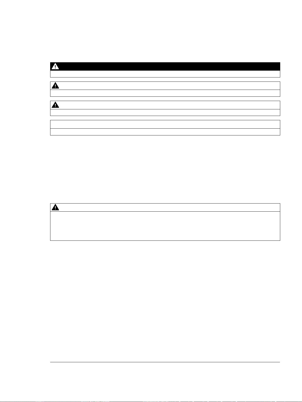
①
LEDs for the I/O
②
Terminal connectors
③
Ethernet
④
Clip for installation on a
standard (DIN) rail
⑤
Ethernet status LEDs
(under door): LINK, Rx/Tx
⑥
Status LEDs: RUN, STOP and
ERROR
⑦
RS485 Communication port
⑧
Optional signal board
(Standard models only)
⑨
Memory card r
door)
(Standard models only)
Note
CPU CR40 and CPU CR60
S7
CR60 models.
1.1 S7-200 SMART CPU
The CPU combines a microprocessor, an integrated power supply, input circuits, and output
circuits in a compact housing to create a powerful Micro PLC. After you have downloaded
your program, the CPU contains the logic required to monitor and control the input and
output devices in your application.
The CPU provides different models with a diversity of features and capabilities that help you
create effective solutions for your varied applications. The different models of CPUs are
shown below. For detailed information about a specific CPU, see the technical specifications
(Page 685).
communication port
eader (under
S7-200 SMART
18 System Manual, V2.3, 07/2017, A5E03822230-AF
-200 SMART CPU firmware release V2.3 does not apply to the CPU CR40 and CPU

Product overview
SR20
ST20
CR20s
SR30
ST30
CR30s
SR40
ST40
CR40s
SR60
ST60
CR60s
expandable
Relay output
X X X X X X X
X
I/O points (built-in)
20
20
20
30
30
30
40
40
40
60
60
60
Features
CPU CR20s
CPU CR30s
CPU CR40s
CPU CR60s
Dimensions: W x H x D (mm)
90 x 100 x 81
110 x 100 x 81
125 x 100 x 81
175 x 100 x 81
Program
12 Kbytes
12 Kbytes
12 Kbytes
12 Kbytes
User data
8 Kbytes
8 Kbytes
8 Kbytes
8 Kbytes
Retentive
2 Kbytes max.1
2 Kbytes max.1
2 Kbytes max.1
2 Kbytes max.1
Expansion modules
None
None
None
None
Signal board
None
None
None
None
phase
A/B phase
2 at 50 kHz
2 at 50 kHz
2 at 50 kHz
2 at 50 kHz
PID loops
8 8 8
8
back-up
1
ues on retentive timers) to be retentive, up to the specified maximum amount.
1.1 S7-200 SMART CPU
Table 1- 1 S7-200 SMART CPUs
Compact serial, non-
X X X X
Standard, expandable X X X X X X X X
Transistor output (DC) X X X X
Table 1- 2 Compact serial, non-expandable CPUs
User memory
On-board digital I/O
High-speed
• Inputs
• Outputs
Single
• 12 DI
• 8 DQ Relay
• 18 DI
• 12 DQ Relay
• 24 DI
• 16 DQ Relay
4 at 100 kHz 4 at 100 kHz 4 at 100 kHz 4 at 100 kHz
36 DI
24 DQ Relay
counters (4
total)
Real-time clock with 7-day
No No No No
You can configure areas of V memory, M memory, C memory (current values), and portions of T memory (current val-
S7-200 SMART
System Manual, V2.3, 07/2017, A5E03822230-AF
19

Product overview
Features
CPU SR20,
CPU ST20
CPU SR30,
CPU ST30
CPU SR40,
CPU ST40
CPU SR60,
CPU ST60
Dimensions: W x H x D (mm)
90 x 100 x 81
110 x 100 x 81
125 x 100 x 81
175 x 100 x 81
User data
8 Kbytes
12 Kbytes
16 Kbytes
20 Kbytes
Retentive
10 Kbytes max.1
10 Kbytes max.1
10 Kbytes max.1
10 Kbytes max.1
Signal board
1 1 1
1
2 at 30 kHz
1 at 30 kHz
2 at 30 kHz
2 at 30 kHz
2 at 20 kHz
1 at 20 kHz
2 at 20 kHz
2 at 20 kHz
Pulse outputs 2
2 at 100 kHz
3 at 100 kHz
3 at 100 kHz
3 at 100 kHz
PID loops
8 8 8
8
Real-time clock with 7-day back-up
Yes
Yes
Yes
Yes
1
2
The specified maximum pulse frequency is possible only for CPU models with transistor outputs. Pulse output operation
is not recommended for CPU models with relay outputs.
1.1 S7-200 SMART CPU
Table 1- 3 Standard expandable CPUs
User memory Program 12 Kbytes 18 Kbytes 24 Kbytes 30 Kbytes
On-board digital
I/O
• Inputs
• Outputs
• 12 DI
• 8 DQ
• 18 DI
• 12 DQ
• 24 DI
• 16 DQ
• 36 DI
• 24 DQ
Expansion modules 6 max. 6 max. 6 max. 6 max.
High-speed
Single phase 4 at 200 kHz
5 at 200 kHz
4 at 200 kHz
4 at 200 kHz
counters (6
total)
A/B phase 2 at 100 kHz
3 at 100 kHz
2 at 100 kHz
2 at 100 kHz
You can configure areas of V memory, M memory, C memory (current values), and portions of T memory (current val-
ues on retentive timers) to be retentive, up to the specified maximum amount.
Refer to the technical specifications (Page 679) for the power requirements of the CPU and
the expansion modules. Use the worksheets in Appendix B, Calculating a power budget
(Page 790) to calculate your power budget.
S7-200 SMART
20 System Manual, V2.3, 07/2017, A5E03822230-AF

Product overview
1.2
New features
New CPU models
Note
CPU CR40 and CPU CR60
S7
CR60 models.
Status LED states
High Speed Counters (HSC)
USB/PPI serial interface support by STEP 7-Micro/WIN SMART
1.2 New features
STEP 7-Micro/WIN SMART V2.3 and the S7-200 SMART V2.3 CPUs introduce the following
new features:
S7-200 SMART has four new compact serial CPU models:
● CPU CR20s AC/DC/Relay (6ES7288-1CR20-0AA1)
● CPU CR30s AC/DC/Relay (6ES7288-1CR30-0AA1)
● CPU CR40s AC/DC/Relay (6ES7288-1CR40-0AA1)
● CPU CR60s AC/DC/Relay (6ES7288-1CR60-0AA1)
-200 SMART CPU firmware release V2.3 does not apply to the CPU CR40 and CPU
All CPU models now blink the STOP LED at 1 Hz if a value is forced (in RUN or STOP
mode).
New HSC capabilities are as follows:
● The number of HSCs increased from four to six on the SR and ST CPU models. The new
CRs CPUs have four HSCs.
● The SR/ST30 CPUs now utilize the high speed inputs I0.6 and I0.7 for HSC4. This means
that the SR/ST30 CPU has one more 200 kHz counter than the other SR/ST models.
You can now use a USB/PPI Multi-Master cable to program all CPU models through any of
the following serial ports:
● RS485 port
● Signal board port
● DP01 PROFIBUS port
S7-200 SMART
System Manual, V2.3, 07/2017, A5E03822230-AF
21

Product overview
Firmware update with STEP 7-Micro/WIN SMART
See also
1.2 New features
You can now download firmware updates on all CPU models through any of the following
serial ports:
● RS485 port
● Signal board port
● DP01 PROFIBUS port
Creating a user-defined library of instructions (Page 563)
EM DE08 and EM DE16 digital input specifications (Page 725)
EM DT08, EM DR08, EM QR16, and EM QT16 digital output specifications (Page 727)
S7-200 SMART I/O expansion cable (Page 779)
Using STEP 7-Micro/WIN SMART to create your programs (Page 111)
Modbus RTU library (Page 476)
Open user communication library (Page 498)
Open user communication (Page 217)
S7-200 SMART
22 System Manual, V2.3, 07/2017, A5E03822230-AF

Product overview
1.3
CPU feature differences
CRs models
No Ethernet port
1.3 CPU feature differences
The S7-200 SMART V2.3 CPU family includes twelve CPU models, separated into two lines:
the Compact Line and the Standard Line. The first letter of the CPU designator indicates a
line, either Compact (C) or Standard (S). The second letter of the designator indicates AC
power supply / relay outputs (R) or DC power supply / DC transistor (T). The number in the
designator indicates the total onboard digital I/O count. The new compact models are
designated by a lower case "s" character (serial port only) following the I/O count.
The CPU CR20s, CPU CR30s, CPU CR40s, and CPU CR60s models have the following
differences from the standard CPUs:
● No Ethernet port: The RS485 port is now the programming port.
● STEP 7-Micro/WIN SMART uses a USB-PPI cable to program the CPU through the
RS485 port.
● The CPUs reserve one connection for the STEP 7-Micro/WIN SMART programmer
connection.
● No CPU instructions that require an Ethernet port
● No support for data logs
● No real-time clock
● No microSD card reader
● No signal board support
● No signal module support
● No 24 V DC sensor supply
● No motion control
● Support for only PROFIBUS/RS485-capable HMIs
● 12 KB of ladder memory and 8 KB of V memory
● Retentive memory limited to 2 KB
Because the CRs models have no Ethernet port, the RS485 port is the programming port.
STEP 7-Micro/WIN SMART uses the USB-PPI cable to program the CPU. You can now
program any CPU over all serial ports, including the PROFIBUS DP01 modules.
S7-200 SMART
System Manual, V2.3, 07/2017, A5E03822230-AF
23

Product overview
USB-PPI cable
Communication connections
No CPU instructions that require an Ethernet port
LAD instruction
STL instruction
Description
GET
GET
Get data through the Ethernet
GIP_ADDR
GIP
Get Ethernet IP address
SIP_ADDR
SIP
Set Ethernet IP address
TCON
TCON
Open an OUC Ethernet connection
TSEND
TSEND
Send OUC data through the Ethernet
net
tion
No real-time clock
No microSD card reader or any functions related to the use of a microSD card
1.3 CPU feature differences
The CRs models provide the RS485 port as the only programming port for the CPU. Using
STEP 7-Micro/WIN SMART and a USB-PPI cable, you can perform the following tasks:
● Upload and download your program
● Monitor program functions
● Perform firmware updates
If you use Freeport (Page 465) in your program, attaching a USB-PPI cable forces the CPU
to exit Freeport mode and enables PPI mode. PPI mode allows STEP 7-Micro/WIN SMART
to regain control of the CPU.
Since the CRs CPU models support only an RS485 programming port, the CPU always
reserves one connection for the STEP 7-Micro/WIN SMART programmer connection. The
CRs model CPUs still support four connections on the RS485 port for HMIs.
You cannot use the CPU instructions that utilize the Ethernet port on the CRs models. The
instructions that are not available in the CRs models are as follows:
SET SET Write data through the Ethernet
TRECV TRECV Receive OUC data through the Ether-
TDCON TDCON Disconnect an OUC Ethernet connec-
The CRs models do not have a real-time clock; however, the CRs models still support time
instructions. The time resets to the default time (January 1, 2000) on every power cycle. The
CPU maintains time with limited accuracy without the real-time clock.
Because the CRs models do not support a microSD card, you use the Reset to factory
defaults command (Page 164) using the RS485 port in case you forget your password.
S7-200 SMART
24 System Manual, V2.3, 07/2017, A5E03822230-AF

Product overview
HMIs limited to those accessible from PROFIBUS/RS485 networks
1.3 CPU feature differences
The new CRs models only support the following PROFIBUS/RS485-capable HMIs:
● COMFORT HMIs:
– SIMATIC HMI TP700 COMFORT
– SIMATIC HMI TP900 COMFORT
– SIMATIC HMI TP1200 COMFORT
– SIMATIC HMI KP400 COMFORT
– SIMATIC HMI KP700 COMFORT
– SIMATIC HMI KP900 COMFORT
– SIMATIC HMI KP1200 COMFORT
– SIMATIC HMI KTP400 COMFORT
● SMART HMIs:
– SMART 700 IE
– SMART 1000 IE
● BASIC HMIs:
– SIMATIC HMI KTP600 BASIC COLOR DP
– SIMATIC HMI KTP1000 BASIC COLOR DP
● Micro HMIs:
– TD 400C TEXT DISPLAY, 4 LINES
S7-200 SMART
System Manual, V2.3, 07/2017, A5E03822230-AF
25

Product overview
1.4
S7-200 SMART expansion modules
Type
Input only
Output only
Combination In/Out
Other
Module
Type
Description
1.4 S7-200 SMART expansion modules
To better solve your application requirements, the S7-200 SMART family includes a wide
variety of expansion modules, signal boards, and a communications module. You can use
these expansion modules with the standard CPU models (SR20, ST20, SR30, ST30, SR40,
ST40, SR60 or ST60) to add additional functionality to the CPU. The following table provides
a list of the expansion modules that are currently available. For detailed information about a
specific module, see the technical specifications (Page 679).
Table 1- 4 Expansion modules and signal boards
Digital expansion module
Analog expansion modules
Signal boards
• 8 x DC In
• 16 x DC In
• 4 x Analog In
• 8 x Analog In
• 2 x RTD In
• 4 x RTD In
• 4 x TC In
• 1 x Analog In • 1 x Analog Out • 2 x DC In x 2 x DC Out • RS485/RS232
• 8 x DC Out
• 8 x Relay Out
• 16 x Relay Out
• 16 x DC Out
• 2 x Analog Out
• 4 x Analog Out
Table 1- 5 Communication expansion modules
Communication expansion module
(EM)
PROFIBUS DP SMART module EM DP01 PROFIBUS DP
• 8 x DC In / 8 x DC Out
• 8 x DC In / 8 x Relay Out
• 16 x DC In / 16 x DC Out
• 16 x DC In / 16 x Relay Out
• 4 x Analog In / 2 x Analog Out
• 2 x Analog In / 1 x Analog Out
• Battery Board
S7-200 SMART
26 System Manual, V2.3, 07/2017, A5E03822230-AF
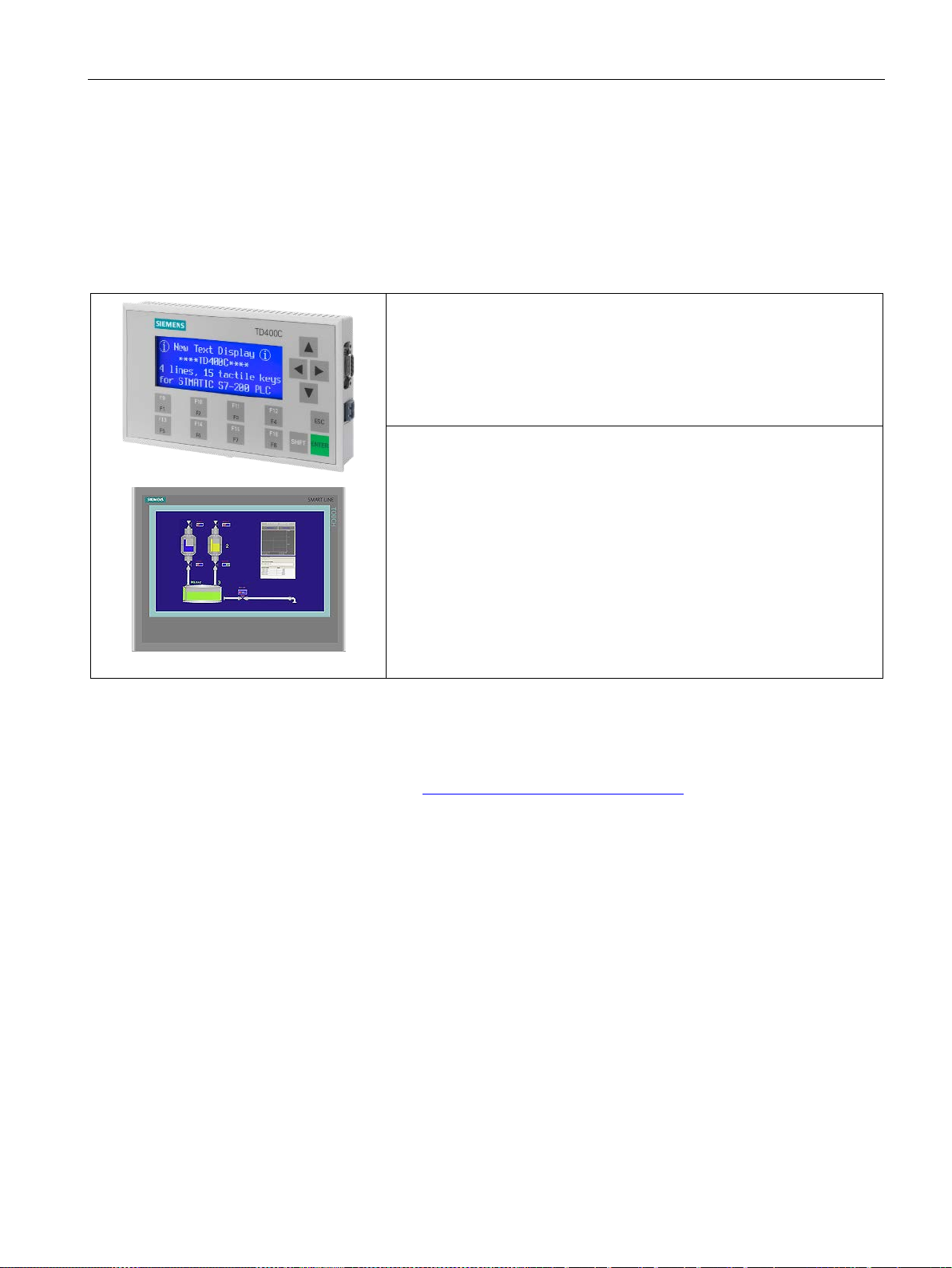
Product overview
1.5
HMI devices for S7-200 SMART
Text Display unit:
to your application.
SMART HMIs:
1.5 HMI devices for S7-200 SMART
The S7-200 SMART supports Comfort HMIs, SMART HMIs, Basic HMIs and Micro HMIs.
The TD400C and the SMART LINE Touch Panel are shown below. Refer to "HMIs and
communication drivers" (Page 398) for a list of supported devices.
Table 1- 6 HMI devices
The TD400C is an RS485-only display device that can be
connected to the CPU. Using the Text Display wizard, you can easily program your CPU to display text messages and other data pertaining to your
application.
The TD400C device provides a low-cost interface to your application by
allowing you to view, monitor, and change the process variables pertaining
The SMART LINE Touch Panel provides operating and
monitoring functions for small-scale machines and plants. Short configuration and commissioning times, their configuration in WinCC flexible (ASIA
version), and a double-port Ethernet/RS485 interface form the highlights of
these HMIs.
The Text Display wizard in STEP 7-Micro/WIN SMART helps you configure Text Display
messages quickly and easily for the TD400C. To start the Text Display wizard, select the
"Text Display" command from the "Tools" menu.
The SIMATIC Text Display (TD) User Manual can be downloaded from the Siemens
customer support web site (http://www.siemens.com/automation/).
S7-200 SMART
System Manual, V2.3, 07/2017, A5E03822230-AF
27

Product overview
1.6
Communications options
Note
The CPU models CPU CR20s, CPU CR30s, CPU CR40s, and CPU CR60s have no
Ethernet port and do not support any functions related to the use of Ethernet
communica
1.6 Communications options
The S7-200 SMART offers several types of communication between CPUs, programming
devices, and HMIs:
● Ethernet:
– Exchange of data from the programming device to the CPU
– Exchange of data between HMIs and the CPU
– S7 peer-to-peer communication with other S7-200 SMART CPUs
– Open User Communication (OUC) with other Ethernet-capable devices
tions.
● PROFIBUS:
– High speed communications for distributed I/O (up to 12 Mbps)
– One bus master connects to many I/O devices (supports 126 addressable devices).
– Exchange of data between the master and I/O devices
– EM DP01 module is a PROFIBUS I/O device.
● RS485:
– Provides a STEP 7-Micro/WIN SMART connection for programming when using a
USB-PPI cable
– Supports a total of 126 addressable devices (32 devices per network segment)
– Supports PPI (point-to-point interface) protocol
– Exchange of data between HMIs and the CPU
– Exchange of data between devices and the CPU using Freeport (XMT/RCV
instructions)
● RS232:
– Supports a point-to-point connection to one device
– Supports PPI protocol
– Exchange of data between HMIs and the CPU
– Exchange of data between devices and the CPU using Freeport (XMT/RCV
instructions)
S7-200 SMART
28 System Manual, V2.3, 07/2017, A5E03822230-AF
Product overview
1.7
Programming software
STEP7
user
edit, and monitor the logic needed to
control your application.
At the top is a quick access toolbar for
frequent tasks, followed by menus for
all common functions. At the left is the
project tre
easy access to components and i
structions. The program editor and
other components that you open o
cupy the remainder of the user inte
face.
STEP7
three program editors (LAD, FBD, and
STL) for convenience and efficiency in
developing the control program for
your application.
Computer requirements
Installing STEP 7-Micro/WIN SMART
Note
To instal
SMART on a Windows XP or Windows 7 operating system, you
must log in with Administrator privileges.
1.7 Programming software
-Micro/WIN SMART provides a
-friendly environment to develop,
e and navigation bar for
n-
c-
r-
-Micro/WIN SMART provides
To help you find the information you need, STEP7-Micro/WIN SMART provides an extensive
online help system.
STEP 7-Micro/WIN SMART runs on a personal computer. Your computer should meet the
following minimum requirements:
● Operating system: Windows 7 or Windows 10 (both 32 bit and 64 bit versions)
● At least 350M bytes of free hard disk space
● Mouse (recommended)
Insert the STEP 7-Micro/WIN SMART CD into the CD-ROM drive of your computer or
contact your Siemens distributor or sales office to download STEP7-Micro/WIN SMART from
S7-200 SMART
System Manual, V2.3, 07/2017, A5E03822230-AF
the customer support web site (Page 3). Installation starts automatically and prompts you
through the installation process. Refer to the Readme file for more information about
installing STEP 7-Micro/WIN SMART.
l STEP 7-Micro/WIN
29

Product overview
1.7 Programming software
S7-200 SMART
30 System Manual, V2.3, 07/2017, A5E03822230-AF
 Loading...