

Page 1

Preface, Contents
Product Overview
1
Getting Started
2
Installing the S7-200
3
PLC Concepts
4
Programming Concepts,
Conventions and Features
5
S7-200 Instruction Set
6
Communicating over a Network
7
Hardware Troubleshooting Guide
and Software Debugging Tools
8
Open Loop Motion Control with
the S7-200
9
Creating a Program for the
Modem Module
10
Using the USS Protocol Library to
Control a MicroMaster Drive
11
Using the Modbus Protocol
Library
12
Using Recipes
13
Using Data Logs
14
PID Auto-Tune and the PID
Tuning Control Panel
15
Appendices
Index
S7-200
Programmable Controller
System Manual
SIMATIC
Edition 08/2008
A5E00307987--04
This manual has the order number:
6ES7298-8FA24--8BH0
Page 2

ii
Safety Guidelines
This manual contains noticeswhichyou should observe to ensure your own personalsafety,as
well as to protecttheproductandconnectedequipment. These notices are highlighted in the
manual by a warning triangleand aremarkedas follows according tothelevelofdanger:
Danger
Danger indicates an imminently hazardous situation which, if not avoided,will result in death or
serious injury.
Warning
Warningindicates a potentially hazardous situation which,ifnotavoided, could result in death or
serious injury.
Caution
Caution used with the safetyalert symbol indicates a potentially hazardous situation which, if not
avoided, may resultinminoror moderate injury.
Caution
Caution used withoutthesafety alertsymbolindicates a potentially hazardous situation which, if
not avoided, may resultinproperty damage.
Notice
Notice indicatesa potential situation which,ifnotavoided, may resultin an undesirableresult or
state.
QualifiedPersonnel
Only qualified personnelshould be allowed to installand work on this equipment.Qualified
persons are defined as persons who are authorized to commission, to ground, and to tag circuits,
equipment,and systems inaccordancewith established safety practicesand standards.
Correct Usage
Note the following:
Warning
This device and its components may only be used for the applicationsdescribed in the catalog
or the technicaldescriptions, and only in connectionwith devices or components from other
manufacturers which have been approved or recommended by Siemens.
This product can only functioncorrectly and safely if it is transported,stored, set up, and
installedcorrectly,and operatedand maintained as recommended.
Trademarks
SIMATICR,SIMATIC HMIR and SIMATICNETR are registered trademarks of SIEMENS AG.
Some of other designations used in these documents are also registered trademarks; the owner’s rights may be
violated if they are used by third parties for their own purposes.
Wehave checkedthe contentsof this manual fo r agreement with th e hardware and
software described. Since deviations cannot be precluded entirely, we cannot
guarantee fullagreement. However,thedata inthis manualare reviewed regularly
and any necessary corrections included in subsequent editions. Suggestions for
improvementare welcomed.
Disclaimer of LiabilityCopyright Siemens AG 2008All rights reserved
The reproduction, transmission or use of this document or its contents is not
permitted without express writtenauthority.Offenders will be liable fordamages.
Allrights,including rightscreated by patentgrantor registration ofa utilitymodel
or design, arereserved.
Siemens AG
Bereich Automation and Drives
Geschaeftsgebiet Industrial AutomationSystems
Postfach 4848, D- 90327Nuernberg
E SiemensAG 2008
Technicaldata subject tochange.
Siemens Aktiengesellschaft 6ES7298-8FA24-8BH0
Page 3

iii
Preface
Purpose of the manual
The S7-200 series is a line of micro-programmable logic controllers(Micro PLCs) that can control
a variety of automation applications. Compact design, low cost, and a powerful instruction set
make the S7-200 a perfect solution for controlling smallapplications. The wide variety of S7-200
models and the Windows-based programming tool give you the flexibility you need to solve your
automationproblems.
This manual provides information about installing and programming the S7-200 Micro PLCs and
is designed for engineers,programmers,installers, and electricians who have a general
knowledge of programmablelogic controllers.
Required Basic Knowledge
To understand this manual, it is necessary to have a general knowledge of automationand
programmablelogic controllers.
Scope of the Manual
This manual is valid forSTEP 7--Micro/WIN,version 4.0 and the S7-200 CPU product family. For
a complete listoftheS7-200products and order numbersdescribed in this manual, see
AppendixA.
Changes compared to the previous version
This manual has been revised to include two new analog expansion modules and one additional
appendix.
- EM 231 Analog Input RTD, 4 Inputs
- EM 231 Analog Input Thermocouple 8 Inputs
- Appendix H, S7-200CN Products
Certification
The SIMATIC S7-200 products have the following certification:
- Underwriters Laboratories, Inc.UL508 Listed(Industrial Control Equipment),
Registration number E75310
- Canadian Standards Association:CSA C22.2 Number 142 (Process Control Equipment)
- Factory MutualResearch:Class Number 3600, Class Number3611, FM Class I, Division 2,
Groups A, B, C, & D Hazardous Locations, T4A and Class I, Zone 2, IIC, T4
Tip
The SIMATIC S7-200 series meets the CSA standard.
The cULus logo indicates that the S7-200 has been examined and certified by Underwriters
Laboratories(UL)to standards UL 508 and CSA 22.2 No. 142.
Page 4

S7-200 Programmable Controller System Manual
iv
CE Labeling
Refer to the GeneralTechnical Specifications in Appendix A formoreinformation.
C-Tick
The SIMATIC S7-200 products are compliant with requirements of the AS/NZS 2064 (Australian)
standard.
Standards:
The SIMATIC S7-200 products fulfilltherequirement and criteria of IEC 61131 -- 2, Programmable
controllers -- Equipment requirements.
Refer to Appendix A for additional compliance information.
Place of this Documentation in the Information Environment
Product
Family
Documentation Order Number
S7-200 S7-200 Point-to-Point Interface Communication Manual (English/German) 6ES7298--8GA00--8XH0
SIMATIC Text Display User Manual (included on the STEP 7--Micro/WIN
documentation CD)
none
HMI device OP 73micro, TP 177micro (WinCC Flexible) Operating
Instructions (English)
6AV6 691--1DF01--0AB0
SIMATIC HMI WinCC flexible 2005 Micro User’s Manual (English) 6AV6691--1AA01--0AB0
SIMATIC NET CP 243--2 AS-Interface Master Manual (English) 6GK7 243--2AX00--8BA0
SIMATIC NET CP 243--1 Communications processor of Industrial Ethernet
Technical Manual (English)
J31069--D0428--U001--A2--7618
SIMATIC NET CP 243--1 IT Communications Processor of Industrial
Ethernet and Information T echnology Technical Manual (English)
J31069--D0429--U001--A2--7618
SIMATIC NET S7Beans / Applets for IT--CPs Programming Tips (English) C79000--G8976--C180--02
SIMATIC NET GPRS/GSM--Modem SINAUT MD720--3 System manual
(English)
C79000--G8976--C211
SIMATIC NET SINAUT MICRO SC System manual (English) C79000--G8900--C210
SIWAREX MS Device Manual (English) (included with device) none
S7-200 Programmable Controller System Manual (English) 6ES7 298--8FA24--8BH0
Page 5

Preface
v
Finding Your Way
If you are a first-time user of S7-200 Micro PLCs, you should read the entireS7-200
ProgrammableController System Manual. If you are an experienced user, refer to the table of
contents or index to findspecific information.
The S7-200 Programmable Controller SystemManualisorganized according to the following
topics:
- Chapter 1 (ProductOverview) provides an overview of some of the features of the S7-200
familyofMicro PLC products.
- Chapter 2 (Getting Started)provides a tutorial for creating and downloading a sample
control program to an S7-200.
- Chapter 3 (Installing the S7-200) provides the dimensions and basic guidelines for installing
the S7-200 CPU modules and expansion I/O modules.
- Chapter 4 (PLC Concepts) providesinformation about the operation of the S7-200.
- Chapter 5 (Programming Concepts, Conventions,andFeatures) provides information about
the featuresofSTEP7--Micro/WIN, the program editors and types of instructions
(IEC 1131-3 or SIMATIC), S7-200 data types,and guidelines forcreating programs.
- Chapter 6 (S7-200 Instruction Set) provides descriptionsand examples of programming
instructions supportedby the S7-200.
- Chapter 7 (Communicating over a Network)provides information forsetting up the different
network configurations supported by the S7-200.
- Chapter 8 (HardwareTroubleshooting Guide and Software Debugging Tools) provides
information for troubleshooting problems with the S7-200 hardware and about the
STEP 7--Micro/WINfeatures that help you debug your program.
- Chapter 9 (Open Loop Motion Controlwith the S7-200) provides informationaboutthree
methods of open loop motion control:Pulse Width Modulation, Pulse Train Output, and the
EM 253 Position ControlModule.
- Chapter 10 (Creating a Program fortheModemModule) provides information about the
instructions and wizard used to create a programforthe EM 241 Modem module.
- Chapter 11 (Using the USS Protocol Library to ControlaMicroMaster Drive) provides
information about the instructions used to create a controlprogram foraMicroMaster drive.
It also providesinformationabouthowtoconfigure the MicroMaster 3 and MicroMaster4
drives.
- Chapter 12 (Using the Modbus ProtocolLibrary)provides information about the instructions
used to create a program thatuses the Modbus protocolfor communications.
- Chapter 13 (Using Recipes)provides information about organizing and loading automation
program recipesinthememory cartridge.
- Chapter 14 (Using Data Logs) providesinformation about storing process measurement
data in the memory cartridge.
- Chapter 15 (PID Auto-Tune and the PID TuningControl Panel)providesinformation about
using these featurestogreatly enhance the utility and ease of use of the PID function
provided by the S7-200.
- Appendix A (Technical Specifications)provides the technicalinformation and data sheets
about the S7-200 hardware.
The other appendices provide additional referenceinformation,suchas descriptions of the error
codes, descriptionsofthe Special Memory (SM)area,part numbers for ordering S7-200
equipment,STL instruction execution times, and S7-200CN product information.
In addition tothis manual, STEP 7--Micro/WINprovides extensive online help forgetting started
with programming the S7-200.Included with the purchase of the STEP 7--Micro/WIN software is a
free documentation CD. On this CD you can find application tips,anelectronic version of this
manual and other information.
Page 6

S7-200 Programmable Controller System Manual
vi
Online Help
Help is only a keystroke away! Pressing F1 accesses the extensive onlinehelpfor
STEP 7--Micro/WIN.Theonline help includes useful information about gettingstarted with
programmingtheS7-200, as well as many other topics.
Electronic Manual
An electronic versionofthis S7-200 System Manual is availableon the documentation CD. You
can installtheelectronic manual onto your computer so that you can easily access the information
in the manual while you are working withtheSTEP7--Micro/WIN software.
Programming Tips
The documentation CD includes Programming Tips,asetofapplic ation examples with sample
programs.Reviewing or modifying these examplescan help you find efficient or innovative
solutions foryourownapplication. You can also findthemostcurrent version of Programming Tips
on the S7-200 Internetsite.
Recycling and Disposal
Please contact a company certified in the disposalofelectronic scrap for environmentallysafe
recyclingand disposalofyourdevice.
Additional Support
Local Siemens Sales Office or Distributor
For assistance in answeringany technicalquestions, for training on the S7-200 products,orfor
ordering S7-200products , contact your Siemens distributororsales office.Becauseyoursales
representatives are technically trained and have the most specificknowledgeaboutyour
operations,process and industry, as wellas about the individual Siemens products that you are
using, they can provide the fastestandmostefficient answers to any problems thatyou might
encounter.
Service & Support on the Internet
In addition to ourdocumentation, we offer our Know-how online on the Internetat:
http://www
.siemens.com/automation/service&support
where you will find the following:
- www.siemens.com/S7--200 for S7-200 productinformation
The S7-200 Internetsite includes frequently asked questions(FAQs), ProgrammingTips
(application examples and sample programs), information about newly released products,
and product updates or downloads.
- The newsletter, which constantly provides you with up-to-date information on your products.
- The right documents via our Search function in Service& Support.
- A forum, whereusersand expertsfrom allovertheworld exchange theirexperiences.
- Your local representative for Automation & Drives.
- Information on field service,repairs, spareparts and more under “Services”.
Techn ical Services
The highly trainedstaff of the S7-200 Technical Services centerisalsoavailable to help you solve
any problems that you mightencounter. You can call on them 24 hours a day, 7 days a week.
Page 7

Preface
vii
A&D Technical Support
Worldwide, available 24 hours a day:
Johnson City
Nuernberg
Beijing
Technical Support
Worldwide (Nuernberg)
Technical Support
24 hours a day, 365 days a year
Phone: +49 (180) 5050-222
Fax: +49 (180) 5050-223
mailto:[email protected]
GMT: +1:00
United States (Johnson City)
Technical Support and
Authorization
Local time: Mon.-Fri.
8:00 AM to 5:00 PM
Phone: +1 (423) 262 2522
+1 (800) 333--7421 (USA only)
Fax: +1 (423) 262 2289
mailto:simatic.hotline
@
sea.siemens.com
Asia / Australia (Beijing)
Technical Support and
Authorization
Local time: Mon.-Fri.
8:00 AM to 5:00 PM
GMT: +8:00
Europe / Africa (Nuernberg)
Authorization
Local time: Mon.-Fri.
8:00 AM to 5:00 PM
GMT: +1:00
mailto:simati
GMT : --5:00
The languages of the SIMATIC Hotlines and the authorization hotline are generally German and English.
Page 8

S7-200 Programmable Controller System Manual
viii
Page 9

ix
Contents
1 Product Overview 1.......................................................
What’sNew? 2....................................................................
S7-200 CPU 2....................................................................
S7-200 Expansion Modules 4.......................................................
STEP 7--Micro/WIN ProgrammingPackage 5..........................................
CommunicationsOptions 5.........................................................
Display Panels 6..................................................................
2 Getting Started 7..........................................................
Connecting the S7-200 CPU 8......................................................
Creating a Sample Program 10.......................................................
Downloading the Sample Program 14.................................................
Placing the S7-200 in RUN Mode 14..................................................
3 Installing the S7-200 15.....................................................
Guidelines for Installing S7-200 Devices 16............................................
Installing and Removing the S7-200 Modules 17........................................
Guidelines forGrounding and Wiring 20...............................................
4 PLC Concepts 23...........................................................
Understanding How the S7-200 Executes Your Control Logic 24..........................
Accessing the Data of the S7-200 27..................................................
Understanding How the S7-200 Saves and Restores Data 36.............................
Selecting the Operating Mode for the S7-200 CPU 40....................................
Using the S7-200 Explorer 41........................................................
Features of the S7-200 41...........................................................
5 Programming Concepts, Conventions, and Features 51.......................
Guidelines forDesigning a MicroPLC System 52.......................................
Basic Elements of a Program 53......................................................
Using STEP 7--Micro/WINtoCreate Your Programs 55..................................
Choosing Between the SIMATIC and IEC 1131--3 Instruction Sets 57......................
Understanding theConventions Used by the Program Editors 58..........................
Using Wizards To Help You Create Your Control Program 60..............................
Handling ErrorsintheS7-200 60.....................................................
Assigning Addresses and Initial Values in the Data Block Editor 62........................
Using the Symbol Table for Symbolic Addressing of Variables 62..........................
Using Local Variables 63............................................................
Using the Status Chart to Monitor Your Program 63......................................
Creating an Instruction Library 64.....................................................
Features forDebuggingYour Program 64..............................................
Page 10

S7-200 Programmable Controller System Manual
x
6 S7-200 Instruction Set 65...................................................
Conventions Used to Describe the Instructions 67.......................................
S7-200 Memory Ranges and Features 68..............................................
Bit Logic Instructions 70.............................................................
Contacts 70...................................................................
Coils 73.......................................................................
Logic Stack Instructions 75......................................................
Set and Reset Dominant BistableInstructions 77....................................
Clock Instructions 78................................................................
CommunicationsInstructions 81......................................................
Network Read and Network Write Instructions 81....................................
Transmitand Receive Instructions (Freeport) 86....................................
Get Port Address and Set PortAddressInstructions 95..............................
Compare Instructions 96............................................................
Comparing NumericalValues 96..................................................
Compare String 98.............................................................
Conversion Instructions 99...........................................................
Standard ConversionInstructions 99..............................................
ASCII ConversionInstructions 103.................................................
String ConversionInstructions 107.................................................
Encode and Decode Instructions 112...............................................
Counter Instructions 113..............................................................
SIMATIC Counter Instructions 113.................................................
IEC Counter Instructions 116......................................................
High-Speed CounterInstructions 118...................................................
Pulse Output Instruction 133..........................................................
Math Instructions 140................................................................
Add, Subtract,Multiply,andDivideInstructions 140...................................
MultiplyInteger to Double Integer and Divide Integer with Remainder 142................
Numeric FunctionsInstructions 143................................................
Incrementand DecrementInstructions 144..........................................
Proportional/Integral/Derivative (PID)Loop Instruction 145.................................
Interrupt Instructions 153.............................................................
Logical Operations Instructions 161....................................................
InvertInstructions 161............................................................
AND, OR, and Exclusive OR Instructions 162........................................
Move Instructions 164................................................................
Move Byte, Word,Double Word,or Real 164........................................
Move Byte Immediate(Readand Write) 165.........................................
Block Move Instructions 166......................................................
Program ControlInstructions 167......................................................
ConditionalEnd 167.............................................................
Stop 167.......................................................................
Watchdog Reset 167.............................................................
For--Next Loop Instructions 169....................................................
Jum
p Instructions 171............................................................
Sequence Control Relay (SCR)Instructions 172.....................................
Diagnostic LED Instruction 178....................................................
Page 11

Contents
xi
Shift and RotateInstructions 179.......................................................
Shift RightandShift Left Instructions 179............................................
Rotate Right and RotateLeftInstructions 179........................................
Shift RegisterBit Instruction 181...................................................
Swap Bytes Instruction 183.......................................................
String Instructions 184...............................................................
Table Instructions 189................................................................
AddToTable 189................................................................
First-In-First-Outand Last-In-First-Out 190..........................................
Memory Fill 192.................................................................
Table Find 193..................................................................
TimerInstructions 196................................................................
SIMATIC Timer Instructions 196...................................................
IEC TimerInstructions 201........................................................
Interval Timers 203..............................................................
Subroutine Instructions 204...........................................................
7 Communicating over a Network 209..........................................
Understanding theBasicsofS7-200Network Communications 210.........................
Selecting the Communications Protocolfor Your Network 214..............................
Installing and Removing Communications Interfaces 220..................................
Building Your Network 221............................................................
Creating User-Defined Protocolswith Freeport Mode 226.................................
Using Modems and STEP 7--Micro/WIN with Your Network 228............................
Advanced Topics 233................................................................
ConfiguringtheRS-232/PPI Multi-Master Cable forRemoteOperation 239...................
8 Hardware Troubleshooting Guide and Software Debugging Tools 243...........
Features forDebuggingYour Program 244..............................................
Displaying the ProgramStatus 246.....................................................
Using a Status Chart to Monitorand ModifytheDataintheS7-200 247......................
Forcing SpecificValues 248...........................................................
Running Your Program fora Specified Number of Scans 248..............................
Hardware Troubleshooting Guide 249..................................................
9 Open Loop Motion Control with the S7-200 251................................
Overview 252.......................................................................
Using the PWM (Pulse WidthModulation) Output 253.....................................
Basic Information for Open Loop Position ControlUsing SteppersorServos 255..............
Instructions Createdby the Position ControlWizard 260...................................
ErrorCodes forthePTO Instructions 264...............................................
Features of the Position Module 265...................................................
ConfiguringthePosition Module 267...................................................
Instructions Createdby the Position ControlWizard for the Position Module 273..............
Sample Programs forthePosition Module 285...........................................
Monitoringthe Position Module withtheEM253 ControlPanel 290.........................
ErrorCodes forthePosition Module and the Position Instructions 292.......................
Advanced Topics 294................................................................
Understanding theRP Seek Modes Supported by the PositionModule 303..................
Page 12

S7-200 Programmable Controller System Manual
xii
10 Creating a Program for the Modem Module 307................................
Features of the Modem Module 308....................................................
Using the Modem Expansion Wizard to Configure the Modem Module 314...................
Overview of Modem Instructions and Restrictions 318....................................
Instructions fortheModemModule 319.................................................
Sample Program fortheModemModule 323............................................
S7-200 CPUs that Support Intelligent Modules 323.......................................
Special Memory Locationforthe Modem Module 323.....................................
Advanced Topics 325................................................................
Messaging Telephone Number Format 327..............................................
Text Message Format 328............................................................
CPU Data TransferMessageFormat 329...............................................
11 Using the USS Protocol Library to Control a MicroMaster Drive 331.............
RequirementsforUsing the USS Protocol 332...........................................
CalculatingtheTime Required forCommunicating with the Drive 332.......................
Using the USS Instructions 333........................................................
Instructions fortheUSS Protocol 334...................................................
Sample Programs fortheUSS Protocol 341.............................................
USS Execution ErrorCodes 342.......................................................
Connecting and SettingUp the MicroMaster Series 3 Drive 342............................
Connecting and SettingUp the MicroMaster Series 4 Drive 345............................
12 Using the Modbus Protocol Library 347.......................................
Overview 348.......................................................................
RequirementsforUsing Modbus Protocol 348...........................................
Initialization and Execution Time for Modbus Protocol 349.................................
Modbus Addressing 350..............................................................
Using the Modbus Master Instructions 351..............................................
Using the Modbus Slave Instructions 352...............................................
Instructions fortheModbus Protocol 353................................................
Advanced Topics 362................................................................
13 Using Recipes 365...........................................................
Overview 366.......................................................................
Recipe Definition and Terminology 367.................................................
Using the Recipe Wizard 367..........................................................
Instructions Createdby the Recipe Wizard 371..........................................
14 Using Data Logs 373........................................................
Overview 374.......................................................................
Using the Data Log Wizard 375........................................................
Instruction Created by the Data Log Wizard 379..........................................
15 PID Auto-Tune and the PID Tuning Control Panel 381..........................
Understanding thePIDAuto-Tune 382..................................................
Expanded Loop Table 382............................................................
Prerequisites 385....................................................................
Auto-Hysteresis and Auto-Deviation 385................................................
Auto-TuneSequence 386.............................................................
Page 13

Contents
xiii
Exception Conditions 387.............................................................
Notes Concerning PV Out-of-Range (ResultCode3) 387..................................
PID Tuning ControlPanel 388.........................................................
A Technical Specifications 391.................................................
General Technical Specifications 392...................................................
CPU Specifications 396..............................................................
DigitalExpansionModules Specifications 405...........................................
Analog Expansion Modules Specifications 412...........................................
Thermocouple and RTD Expansion ModulesSpecifications 424............................
EM 277 PROFIBUS--DP Module Specifications 438......................................
EM 241 Modem Module Specifications 450..............................................
EM 253 Position Module Specifications 452.............................................
(CP 243--1) Ethernet Module Specifications 458.........................................
(CP 243--1 IT) Internet Module Specifications 460........................................
(CP 243--2) AS--Interface Module Specifications 463......................................
Optional Cartridges 465..............................................................
I/O Expansion Cable 466.............................................................
RS-232/PPI Multi-Master Cable and USB/PPI Multi-MasterCable 467......................
Input Simulators 471.................................................................
B Calculating a Power Budget 473..............................................
C Error Codes 477.............................................................
Fatal ErrorCodesand Messages 478..................................................
Run-TimeProgramming Problems 479.................................................
Compile Rule Violations 480..........................................................
D Special Memory (SM) Bits 481................................................
SMB0: Status Bits 482...............................................................
SMB1: Status Bits 482...............................................................
SMB2: FreeportReceiveCharacter 483................................................
SMB3: FreeportParity Error 483.......................................................
SMB4: Queue Overflow 483...........................................................
SMB5: I/O Status 484................................................................
SMB6: CPU ID Register 484..........................................................
SMB7: Reserved 484................................................................
SMB8 to SMB21: I/O Module ID and ErrorRegisters 485..................................
SMW22 to SMW26: Scan Times 486...................................................
SMB28 and SMB29: Analog Adjustment 486............................................
SMB30 and SMB130: Freeport ControlRegisters 486.....................................
SMB31 and SMW32: Permanent Memory (EEPROM) Write Control 487.....................
SMB34 and SMB35: Time IntervalRegisters forTimed Interrupts 487.......................
SMB36 to SMB65: HSC0, HSC1, and HSC2 Register 487.................................
SMB66 to SMB85: PTO/PWMRegisters 489............................................
SMB86 to SMB94, and SMB186 to SMB194: Receive Message Control 490.................
SMW98: Errorson theExpansionI/O Bus 491...........................................
SMB130: FreeportControl Register (see SMB30) 491....................................
SMB131 to SMB165: HSC3, HSC4, and HSC5 Register 491...............................
SMB166 to SMB185: PTO0, PTO1Profile Definition Table 492.............................
Page 14

S7-200 Programmable Controller System Manual
xiv
SMB186 to SMB194: Receive Message Control (see SMB86 to SMB94) 492.................
SMB200 to SMB549: Intelligent Module Status 493.......................................
E S7-200 Order Numbers 495...................................................
F Execution Times for STL Instructions 499.....................................
G S7-200 Quick Reference Information 505......................................
H S7-200CN Products 511......................................................
Certifications and Approvals for S7-200CN Products 512..................................
S7-200CN Products 513..............................................................
Page 15

1
Product Overview
The S7-200 series of micro-programmable logic controllers(Micro PLCs) can controla wide
variety of devices tosupportyourautomation needs.
The S7-200 monitors inputsand changes outputs as controlled by the user program,which can
include Boolean logic,counting, timing,complex math operations, and communications withother
intelligent devices. The compact design, flexible configuration, and powerful instructionset
combine to make the S7-200 a perfect solution forcontrolling a wide variety of applications.
In This Chapter
What’sNew? 2....................................................................
S7-200 CPU 2....................................................................
S7-200 Expansion Modules 4.......................................................
STEP 7--Micro/WIN ProgrammingPackage 5..........................................
CommunicationsOptions 5.........................................................
Display Panels 6..................................................................
Page 16
S7-200 Programmable Controller System Manual
2
What’s New?
The new features of the SIMATIC S7-200 include two new analog expansion modules:
- EM 231 Analog Input RTD, 4 Inputs
- EM 231 Analog Input Thermocouple 8 Inputs
- Appendix H, S7-200CN Products
S7-200 CPU
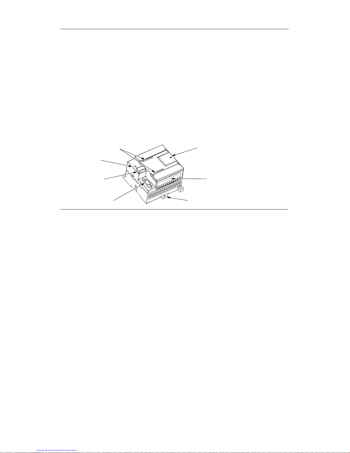
The S7-200 CPU combines a microprocessor, an integrated power supply, input circuits, and
output circuits in a compact housing to create a powerfulMic ro PLC. See Figure 1-1. After you
have downloaded your program, the S7-200contains the logic required tomonitor and control the
input and output devices in your application.
I/OLEDs
Status LEDs:
System Fault/Diagnostic
(SF/DIAG)
RUN
STOP
Optional cartridge:
Memory Cartridge
Real-time Clock
Battery
Communications port
Terminal connector
(removable on CPU 224, CPU 224XP
and CPU 226)
Clip for installation on a standard (DIN) rail
A
ccess door:
Modeselector switch(RUN/STOP)
Analog adjustment potentiometer(s)
Expansion port (for most CPUs)
Figure 1-1 S7-200 Micro PLC
Page 17

Product Overview Chapter 1
3
Siemens provides different S7-200 CPU models with a diversity of features and capabilities that
help you create effective solutions for your varied applications. Table 1-1 briefly compares some of
the features oftheCPU.Fordetailed information about a specific CPU, see Appendix A.
Table 1-1 Comparison of the S7-200 CPU Models
Feature CPU 221 CPU 222 CPU 224
CPU 224XP
CPU 224XPsi
CPU 226
Physical size(mm) 90 x 80 x 62 90 x 80 x 62 120.5 x 80 x 62 140x 80 x 62 190 x 80 x 62
Program memory:
with run mode edit
without run mode edit
4096 bytes
4096 bytes
4096 bytes
4096 bytes
8192 bytes
12288 bytes
12288 bytes
16384 bytes
16384 bytes
24576 bytes
Data memory 2048 bytes 2048 bytes 8192 bytes 10240 bytes 10240 bytes
Memory backup 50 hours
typical
50 hours
typical
100 hours
typical
100 hours
typical
100 hours
typical
Local on-board I/O
Digital
Analog
6In/4Out--8In/6Out
--
14 In/10 Out--14 In/10 Out
2In/1Out
24 In/16 Out
--
Expansion modules 0 modules 2 modules
1
7 modules
1
7 modules
1
7 modules
1
High-speed counters
Single phase
Two phase
4at30kHz
2at20kHz
4at30kHz
2at20kHz
6at30kHz
4at20kHz
4at30kHz
2 at 200 kHz
3at20kHz
1 at 100 kHz
6at30kHz
4at20kHz
Pulse outputs (DC) 2at20kHz 2at20kHz 2at20kHz 2 at 100 kHz 2at20kHz
Analog adjustments 1 1 2 2 2
Real-time clock Cartridge Cartridge Built-in Built-in Built-in
Communications ports 1 RS--485 1 RS--485 1 RS--485 2 RS--485 2 RS--485
Floating-point math Yes
Digital I/O image size 256 (128 in, 128 out)
Boolean execution
speed
0.22 microseconds/instruction
1 Youmust calculateyourpower budget todetermine howmuchpower (or c urrent) the S7-200CPU canprovide foryour configuration.If theCPU
powerbudget is exceeded,you may notbeable to connectthe maximum numberof modules.See Appendix Afor CPU andexpansion module
power requirements, and Appendix B to calculate your power budget.
Page 18

S7-200 Programmable Controller System Manual
4
S7-200 Expansion Modules
To better solve your application requirements, the S7-200 family includes a wide varietyof
expansion modules. You can use these expansion modules to add additionalfunctionality to the
S7-200 CPU. Table 1-2 provides a list of the expansion modules that are currently available.For
detailed information about a specific module, see Appendix A.
Table 1-2 S7-200 Expansion Modules
Expansion
Modules
Type
Discrete modules
Input 8xDCIn 8xACIn 16 x DC In
Output
4xDCOut 4xRelays 8xRelay
8xDCOut 8xACOut
Combination 4xDCIn/
4xDCOut
8xDCIn/
8xDCOut
16 x DC In/
16 x DC Out
32 x DC In/
32 x DC Out
4xDCIn/
4xRelay
8xDCIn/
8xRelay
16 x DC In/
16 x Relay
32 x DC In/
32 x Relay
Analog modules
Input
4 x Analog In 8 x Analog In 4 x Thermocouple In 8 x Thermocouple In
2xRTDIn 4xRTDIn
Output 2 x Analog Out 4 x Analog Out
Combination 4x Analog In
4 x Analog Out
Intelligent modules
Position Modem PROFIBUS--DP
Ethernet Ethernet IT
Other modules
AS--Interface SIWAREX MS
1
1
Detailed information not included in Appendix A. Please refer to your module documentation.
Page 19

Product Overview Chapter 1
5
STEP 7--Micro/WIN Programming Package
The STEP 7--Micro/WIN programming package provides a user-friendly environment to develop,
edit, and monitorthe logic needed to controlyourapplication.STEP7--Micro/WIN providesthree
program editors for convenience and efficiency in developing the control program foryour
application.To help you find the information you need, STEP 7--Micro/WIN providesan extensive
online help system and a documentationCD thatcontains an electronic versionofthis manual,
applicationtips, and otherusefulinformation.
Computer Requirements
STEP 7--Micro/WINrunson eitherapersonalcomputer or a Siemens programming device, such
as a PG 760. Yourcomputeror programming device should meet the followingminimum
requirements:
- Operatingsystem:
Windows 2000, Windows XP, Vista
- At least 350M bytes of free hard
disk space
- Mouse (recommended)
Figure 1-2 STEP 7--Micro/WIN
Installing STEP 7--Micro/WIN
Insert theSTEP 7--Micro/WINCD intothe CD-ROM drive of your computer. The installation wizard
starts automatically and promptsyou throughtheinstallation process. Refer to the Readme file for
more information about installing STEP 7--Micro/WIN.
Tip
To install STEP 7--Micro/WIN on a Windows 2000, Windows XP, or Windows Vistaoperating
system, you must log in withAdministratorprivileges.
Communications Options
Siemens provides two programming options forconnecting your computer to your S7-200:a direct
connection with a PPI Multi-Mastercable,oraCommunications Processor(CP)card with an MPI
cable.
The PPI Multi-Master programming cable is the most common and economical method of
connecting your computertotheS7-200. This cable connects the communicationsportof the
S7-200 to the serialcommunications of your computer. The PPI Multi-Masterprogramming cable
can also be used to connect other communications devices to the S7-200.
Page 20

S7-200 Programmable Controller System Manual
6
Display Panels
Text Display Units
The Text Display (TD) is a display device that can be connected to the S7-200. Using the Text
Display wizard,youcan easilyprogram your S7-200 to display text messages and other data
pertainingtoyourapplication.
The TD device provides a low cost interfacetoyourapplic ation by allowing you to view, monitor,
and change the process variables pertaining to your application.
The S7-200 product familyprovides fourTD devices:
- The TD100C has a 4-line text
display with2 fontchoices.
- The TD 200C has a 2-line text
display with20 characters per line
for a total of 40 characters.
- The TD 200 has a faceplate which
provides four keys withpredefined,
set-bitfunctions and allowsup to
eight set-bitfunctions.
- The TD400C can have a 2- or
TD 100C
TD 200C
TD 200
TD400C
-
TheTD400Ccanhavea2o
r
4-line textdisplay depending on
your font and characterchoice.
Figure 1-3 Text Display Units
For more information about the TextDisplay Units,refer to the SIMATICText Display (TD) User
Manual on the STEP 7--Micro/WIN docuCD.
The Text Display wizard in STEP 7--Micro/WINhelpsyou configure Text Display messages
quickly and easily. Tostart the Text Display wizard, select the Tools > Text Display Wizardmenu
command.
Operator and To u ch Panel Displays
The OP 73micro and TP 177micro
panels are tailoredtoapplications with
SIMATIC S7-200 Micro PLC and provide
operating and monitoring functions for
small-scale machines and plants. Short
configuration and commissioning times,
and their configuration in WinCC flexible
form the highlights of these panels. In
addition,thesepanelssupportup to 32
configuration languages and five online
languages, includingtheAsian and
Cyrillic charactersets.
The mounting dimensions of the
OperatorPanelOP 73microwith its
graphical 3”displayunitare compatible
with OP3 and TD 200.
Touch Panel TP 177microreplaces the
Touch Panel TP 070/TP 170micro.It can
be mounted vertically to accommodate
additionalapplication
s.Thisfeature
enables its use even when space is
restricted.
Figure 1-4 Operator and TouchPanelDisplays
Text Display
Page 21

7
Getting Started
STEP 7--Micro/WINmakes iteasy foryoutoprogram your S7-200.Injusta few shortstepsusing
a simple example, you can learn how to connect, program, and run your S7-200.
All you need for this example is a PPI Multi-Master cable, an S7-200 CPU, and a programming
device running the STEP 7--Micro/WINprogramming software.
In This Chapter
Connecting the S7-200 CPU 8......................................................
Creating a Sample Program 10.......................................................
Downloading the Sample Program 14.................................................
Placing the S7-200 in RUN Mode 14..................................................
Page 22
S7-200 Programmable Controller System Manual
8
Connecting the S7-200 CPU
Connecting your S7-200 is easy. For this example, you only need to connect power to your
S7-200 CPU and then connect the communications cable between your programming device and
the S7-200 CPU.
Connecting Power to the S7-200 CPU
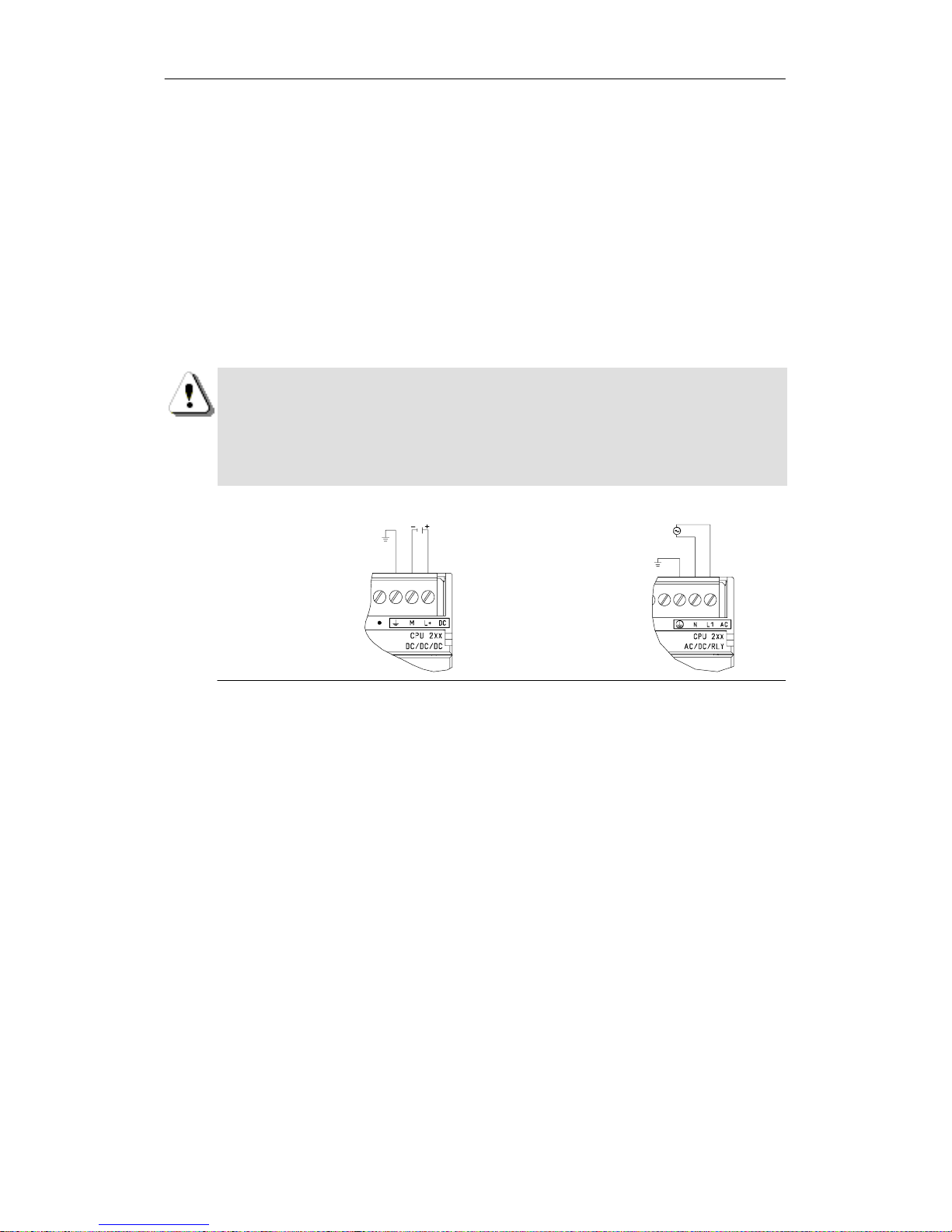
The firststepistoconnecttheS7-200toapowersource.Figure 2-1 shows the wiring
connections for eithera DC or an AC model of the S7-200 CPU.
Before you installorremove any electrical device, ensure thatthepowertothatequipment has
been turned off.Always followappropriate safetyprecautions and ensure thatpowertothe
S7-200 is disabled beforeattempting to install or remove the S7-200.
Warning
Attemptstoinstall or wiretheS7-200orrelated equipment with power applied could cause
electricshock or faulty operation of equipment. Failure to disableallpowerto the S7-200 and
related equipmentduring installation or removalprocedures could resultin death or serious
injury to personnel,and/or damage to equipment.
Always follow appropriate safety precautions and ensure that power to theS7-200isdisabled
before attempting to install or remove the S7-200 or relatedequipment.
DC Installation AC Installation
24VDC 85to 265 VAC
Figure 2-1 Connecting Power to the S7-200 CPU
Page 23
Getting Started Chapter 2
9
Connecting the RS-232/PPI Multi-Master Cable
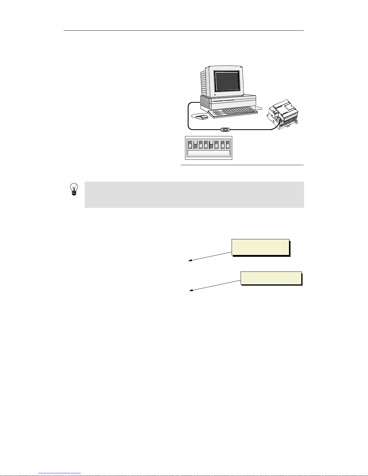
Figure 2-2 shows an RS-232/PPI
Multi-Master cable connectingthe
S7-200 to the programming device. To
connect the cable:
1. Connect the RS-232 connector
(marked “PC”)ofthe RS-232/PPI
Multi-Master cable to the
communicationsportofthe
programmingdevice.(For this
example, connect to COM 1.)
2. Connect the RS-485 connector
(marked “PPI”) of the RS-232/PPI
Multi-Master cable to Port0or
Port 1 of the S7-200.
3. Ensure that the DIP switchesof
-
-
12345678
RS-232/PPI
Multi-Master Cable
S7-200
Programming
Device
↑1--On
↓0--Off
theRS-232/PPIMult
i-Mastercable
are set as shown in Figure 2-2.
Figure 2-2 Connecting the RS-232/PPI Multi-Master Cable
Tip
Examples in this manual use the RS-232/PPIMulti-Master cable. The RS-232/PPIMulti-Master
cable replaces the previous PC/PPIcable. A USB/PPIMulti-Master cable is also available.
Refer to Appendix E for ordernumbers.
Starting STEP 7--Micro/WIN
Click on the STEP 7--Micro/WIN icon to
open a new project. Figure 2-3 shows a
new project.
Notice the navigation bar.You can use
the icons on the navigation bar to open
elements of the STEP 7--Micro/WIN
project.
Click on the Communications icon in the
navigation bartodisplay the
Communicationsdialog box. Youuse
this dialog box to set up the
communicationsforSTEP7--Micro/WIN.
Navigation bar
Communications icon
Figure 2-3 New STEP 7--Micro/WIN Project
Page 24
S7-200 Programmable Controller System Manual
10
Verifying the Communications Parameters for STEP 7--Micro/WIN
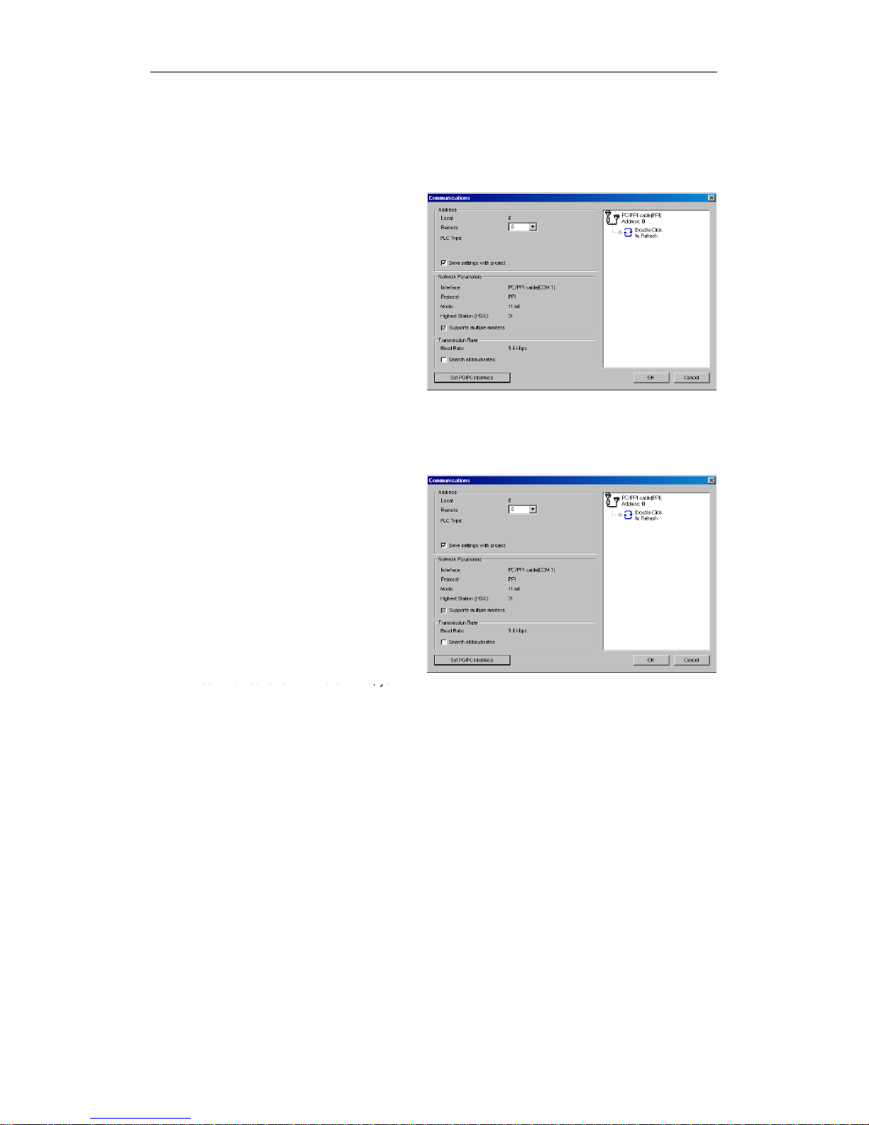
The example project uses the defaultsettings for STEP 7-- Micro/WIN and the RS-232/PPI
Multi-Master cable.To verify these settings:
1. Verify that the address of the
PC/PPI cable in the
Communicationsdialog box is set
to 0.
2. Verify that the interface for the
network parameteris set for
PC/PPI cable(COM1).
3. Verify that the transmission rateis
set to 9.6 kbps.
If you need to change your
communicationsparameter settings, see
Chapter 7.
Figure 2-4 Verifying the Communications Parameters
Establishing Communications with the S7 -200
Use the Communications dialogbox to connect withyourS7-200CPU:
1. Double-clicktherefresh icon in the
Communicationsdialog box.
STEP 7--Micro/WINsearchesfor
the S7-200 stationand displaysa
CPU icon fortheconnected
S7-200 station.
2. Select the S7-200 and click OK.
If STEP 7--Micro/WINdoes not findyour
S7-200 CPU, check the settings forthe
communicationsparameters and repeat
these steps.
After you have established
communicationswith the S7-200, you
coucatostteS00,yo
u
are ready to create and download the
example program.
Figure 2-5 Establishing Communications to the S7-200
Creating a Sample Program
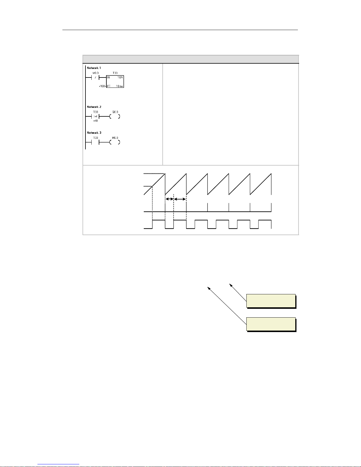
Entering thisexample of a control programwillhelp you understandhow easy it is to use
STEP 7--Micro/WIN.This program uses six instructions in three networks to createa very simple,
self-starting timer that resets itself.
For this example,you use the Ladder (LAD)editor to enter the instructions for the program. The
followingexampleshows the complete program in both LAD and Statement List(STL). The
network comments in the STL programexplain the logic foreachnetwork. The timing diagram
shows the operation of the program.
Page 25
Getting Started Chapter 2
11
Example: Sample Program for getting started with STEP 7--Micro/WIN
Network 1 //10 ms timer T33 times out after
//(100 x 10 ms = 1 s) M0.0 pulse is
// too fast to monitorwithStatusview.
LDN M0.0
TON T33, +100
Network 2 //Comparison becomes true at a
//rate that is visible with
//Status view. Turnon Q0.0 after
//(40 x 10 ms = 0.4s), fora
// 40% OFF/60% ON waveform.
LDW>= T33, +40
=Q0.0
Network 3 //T33 (bit) pulse too fast to monitor with
//Status view. Reset the timer through
//M0.0 after the (100 x 10 ms = 1 s) period.
LD T33
=M0.0
0.4s
0.6s
Timing Diagram
current = 100
current = 40
T33 (current)
T33 (bit)
M0.0
Q0.0
Opening the Program Editor
Click on the Program Block icon to open
the program editor. See Figure 2-6.
Notice the instruction tree and the
program editor. Youuse theinstruction
tree to insert the LAD instructions into
the networks of the programeditor by
dragging and dropping the instructions
from the instruction tree to the networks.
The toolbar icons provideshortcuts to
the menu commands.
After you enterand save the program,
you can download the program to the
S7-200.
Instruction tree
Program editor
Figure 2-6 STEP 7--Micro/WIN Window
Page 26

S7-200 Programmable Controller System Manual
12
Entering Network 1: Starting the Timer
When M0.0 is off(0), this contact turns on and provides power flow to startthetimer. To enter the
contact forM0.0:
1. Either double-click the Bit Logic
icon or click on the plus sign (+) to
display the bitlogic instructions.
2. Select the Normally Closed
contact.
3. Hold down the left mouse button
and drag the contact onto the first
network.
4. Click on the “???” above the
contact and enter the following
address: M0.0
5. Press the Return key to enter the
address for the contact.
Figure 2-7 Network 1
To enter the timer instruction for T33:
1. Double-clicktheTimers icon to displaythetimer instructions.
2. Select the TON (On-Delay Timer).
3. Hold down the left mouse button and drag the timeronto the first network.
4. Click on the “???” above the timerbox and enter thefollowing timernumber: T33
5. Press the Return key to enter the timernumber and to move the focus to the presettime
(PT) parameter.
6. Enter the following value forthepresettime: 100
7. Press the Return key to enter the value.
Entering Network 2: Turning the Output On
When the timervalueforT33isgreater than or equal to 40 (40 times 10 milliseconds, or 0.4
seconds), the contactprovides power flow to turn on outputQ0.0oftheS7-200. To enter the
Compare instruction:
1. Double-clicktheCompareicon to display the compare instructions. Select the >=I
instruction (Greater-Than-Or-Equal-To-Integer ).
2. Hold down the left mouse button
and drag the compare instruction
onto the second network.
3. Click on the “???” above the
contact and enter the address for
the timervalue:T33
4. Press the Return key to enter the
timernumberandtomove the
focus to the other value to be
compared with the timervalue.
5. Enter the following value to be
compared with the timervalue: 40
p
6. Press the Return key to enter the
value.
Figure 2-8 Network 2
To enter the instruction forturning on outputQ0.0:
1. Double-clicktheBitLogic icon to displaythebitlogic instructions and select the outputcoil.
2. Hold down the left mouse button and drag the coilontothesecond network.
3. Click on the “???” above the coil and enter the following address: Q0.0
4. Press the Return key to enter the address forthecoil.
Page 27
Getting Started Chapter 2
13
Entering Network 3: Resetting the Timer
When the timerreachesthepresetvalue (100)and turnsthetimer bit on, the contact for T33 turns
on. Power flow fromthis contactturns on the M0.0 memory location.Because the timer is enabled
by a Normally Closed contact forM0.0, changing the state of M0.0 fromoff (0) to on (1) resets the
timer.
To enter the contact for the timerbitof
T33:
1. Select the Normally Open contact
from the bitlogic instructions.
2. Hold down the left mouse button
and drag the contact onto the third
network.
3. Click on the “???” above the
contact and enter the address of
the timerbit: T33
4.PresstheReturnkeytoenterthe
address for the contact.
Figure 2-9 Network 3
To enter the coil for turning on M0.0:
1. Select the outputcoilfrom the bit logicinstructions.
2. Hold down the left mouse button and drag the outputcoilonto the third network.
3. Double-clickthe“???”above the coil and enterthefollowing address: M0.0
4. Press the Return key to enter the address forthecoil.
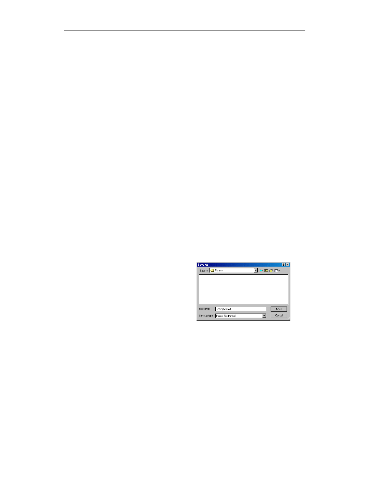
Saving the Sample Project
After entering the three networksofinstructions,you have finishedentering the program. When
you save the program, you create a projectthatincludes the S7-200 CPU type and other
parameters.To save the project:
1. Select the File > Save As menu
command from the menu bar.
2. Enter a name for the projectinthe
Save As dialog box.
3. Click OK to save the project.
After saving theproject, you can
download the program to the S7-200.
Figure 2-10 Saving the Example Program
Page 28
S7-200 Programmable Controller System Manual
14
Downloading the Sample Program
Tip
Each STEP 7--Micro/WIN projectisassociated with a CPU type (CPU 221, CPU 222, CPU 224,
CPU 224XP, or CPU 226). If the project type does not match the CPU to which you are
connected, STEP 7--Micro/WINindicates a mismatchandprompts you to take an action. Ifthis
occurs, choose “ContinueDownload”for this example.
1. Click the Download icon on the
toolbar orselectthe
File > Download menu command
to download the program.See
Figure 2-11.
2. Click OK to download the elements
of the program to the S7-200.
If your S7-200 is in RUN mode, a dialog
box prompts you to place the S7-200 in
STOP mode. ClickYes to place the
S7-200 into STOP mode.
Figure 2-11 Downloading the Program
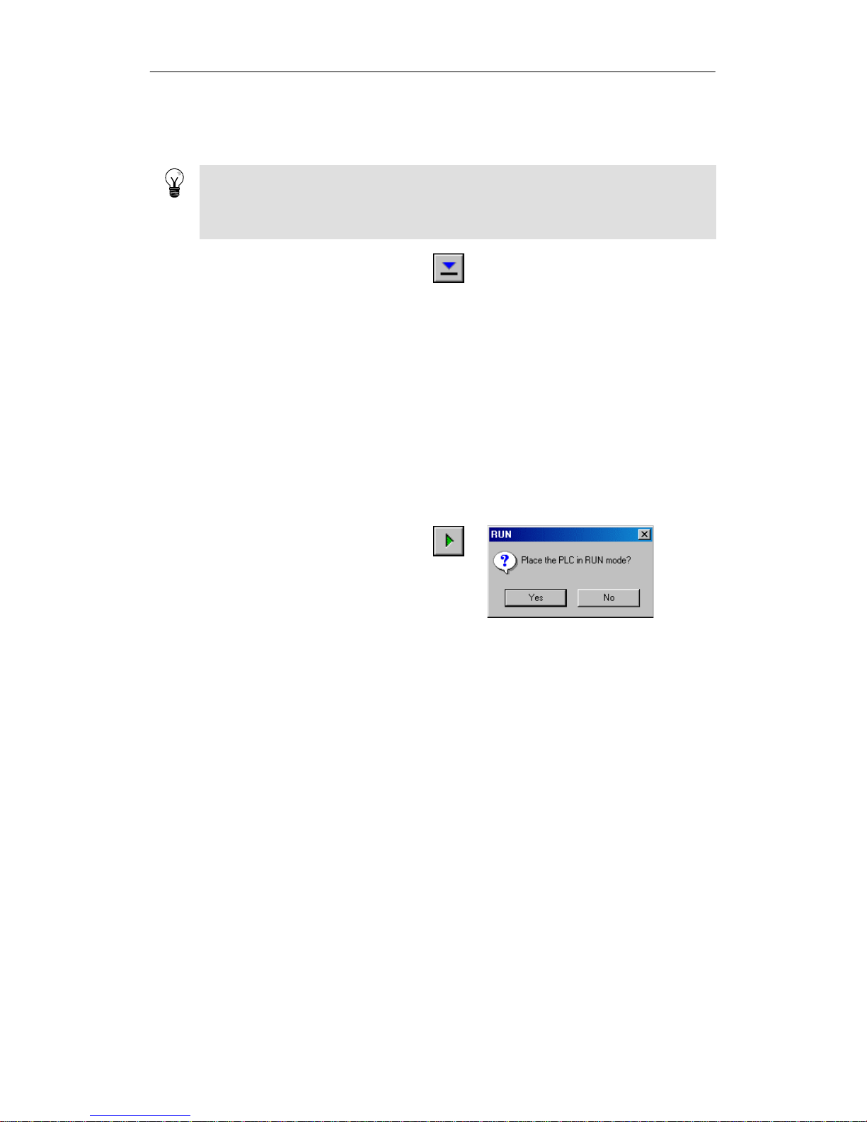
Placing the S7-200 in RUN Mode
For STEP 7--Micro/WIN to place the S7-200CPU in RUN mode, the mode switch of the S7-200
must be set to TERM or RUN. When you place the S7-200 in RUN mode, the S7-200 executes
the program:
1. Click the RUN icon on the toolbar
or select the PLC > RUN menu
command.
2. Click OK to change the operating
mode of the S7-200.
When the S7-200 goes to RUN mode,
g
the outputLED for Q0.0 turns on and o
f
f
as the S7-200 executes the program.
Figure 2-12 Placing the S7-200 in RUN Mode
Congratulations! You have just completed your first S7-200 program.
You can monitor the programby selecting the Debug > Program Status menu command.
STEP 7--Micro/WINdisplays the values for the instructions. To stop the program, place the S7-200
in STOP mode by clicking the STOPiconorbyselecting the PLC > STOP menu command.
Page 29

15
Installing the S7-200
The S7-200 equipment is designed to be easy to install.You can use the mounting holes to attach
the modules to a panel, or you can use the built-inclips to mount the modules onto a standard
(DIN)rail. The small size of the S7-200 allows you to make efficientuseofspace.
This chapter providesguidelines forinstalling and wiring your S7-200 system.
In This Chapter
Guidelines for Installing S7-200 Devices 16............................................
Installing and Removing the S7-200 Modules 17........................................
Guidelines forGrounding and Wiring 20...............................................
Page 30
S7-200 Programmable Controller System Manual
16
Guidelines for Installing S7-200 Devices
You can install an S7-200 eitheron a panel or on a standard rail,andyou can orientthe S7-200
either horizontally or vertically.
Warning
The SIMATIC S7-200 PLCs are Open TypeControllers. It is requiredthatyouinstall the S7-200
in a housing, cabinet,orelectric control room. Entry to thehousing,cabinet, or electric control
room should be limitedto authorized personnel.
Failure tofollow these installation requirements could result in deathorserious injury to
personnel, and/ordamagetoequipment.
Always followtheserequirements when installing S7-200 PLCs.
Separate the S7-200 Devices from Heat, High Voltage, and Electrical
Noise
As a general rule for layingoutthedevicesofyoursystem, always separate the devices that
generate high voltageand high electrical noise from the low-voltage,logic-type devices such as
the S7-200.
When configuringthelayoutof the S7-200 inside your panel, consider the heat-generating
devices and locate the electronic-type devices in the cooler areasofyourcabinet. Operating any
electronicdeviceinahigh-temperature environment willreduce the timetofailure.
Consider also the routing of the wiring forthedevicesinthepanel.Avoid placing low voltage
signal wires and communications cables in the same tray with AC power wiringand high-energy,
rapidly-switched DC wiring.
Provide Adequate Clearance for Cooling and Wiring
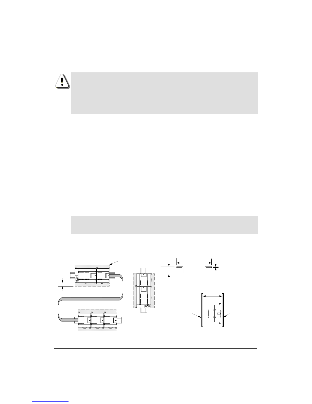
S7-200 devices are designed for naturalconvection cooling. For proper cooling, you must provide
a clearance of at least 25 mm above and below the devices. Also, allowatleast75 mm of depth.
Caution
For verticalmounting, the maximumallowable ambienttemperature is reducedby
10 degrees C. Mount the S7-200 CPU below any expansion modules.
When planning your layout forthe S7-200 system, allow enough clearanceforthe wiring and
communicationscableconnections. For additional flexibility in configuring the layout of the S7-200
system, use the I/Oexpansioncable.
75 mm
Frontofthe
enclosure
Side View
Mounting
surface
35 mm
7.5 mm
1mm
DIN Rail
25 mm
Clearance
Horizontal DIN Rail Mounting with Optional
Expansion Cable (limit one per system)
Vertical Panel
Mounting
Figure 3-1 Mounting Methods, Orientation, and Clearance
Page 31

Installing the S7-200 Chapter 3
17
Power Budget
All S7-200 CPUs have an internal power supply thatprovides power for the CPU, the expansion
modules, and other 24 VDC user power requirements.
The S7-200 CPU provides the 5 VDC logic power needed for any expansion in your system. Pay
careful attention to your system configuration to ensure thatyourCPUcan supply the 5V power
required by your selectedexpansionmodules.If your configuration requires more power than the
CPU can supply,youmustremove a module or select a CPU with more power capability. Refer to
Appendix A for information about the 5 VDC logic budget suppliedby your S7-200 CPU and the
5 VDC power requirementsoftheexpansionmodules.Use Appendix B as a guide for determining
how much power (or current)the CPU can provide for your configuration.
All S7-200 CPUs also provide a 24 VDC sensor supply that can supply 24 VDC for input points,
for relaycoilpowerontheexpansionmodules, or for otherrequirements. If your power
requirements exceed the budget of the sensor supply,then you must add an external24 VDC
power supply to your system. Referto Appendix A for the 24 VDC sensor supply power budget for
your particularS7-200 CPU.
If you requirean external24VDCpowersupply, ensure that the power supply is not connected in
parallelwith the sensor supply of theS7-200CPU.Forimproved electrical noise protection, itis
recommended that thecommons (M)ofthe different power supplies be connected.
Warning
Connecting an external24 VDC power supply in parallelwith the S7-200 24 VDC sensor supply
can result in a conflictbetween the two supplies as each seeks to establish its own preferred
output voltagelevel.
The result of thisconflict can be shortened lifetime or immediate failureofoneorbothpower
supplies, withconsequentunpredictable operation of the PLC system.Unpredictable operation
could resultindeathorserious injurytopersonnel, and/or damage to equipment.
The S7-200 DC sensor supply and any external power supply should provide power to different
points.
Installing and Removing the S7-200 Modules
The S7-200 can be easily installed on a standard DIN railoron a panel.
Prerequisites
Before you installorremove any electrical device, ensure thatthepowertothatequipment has
been turned off.Also, ensure that the power to any related equipment has been turned off.
Warning
Attemptstoinstall or remove S7-200 orrelated equipment withthepowerapplied could cause
electricshock orfaulty operation of equipment.
Failure to disableallpower to the S7-200 and related equipment during installation or removal
procedures could resultin death or serious injurytopersonnel, and/or damage to equipment.
Always follow appropriate safety precautions and ensure that power to theS7-200isdisabled
before attempting to installorremove S7-200 CPUs or related equipment.
Always ensure that whenever you replace or install an S7-200 device you use the correctmodule
or equivalentdevice.
Warning
If you installanincorrect module,theprogram in the S7-200 could function unpredictably.
Failure toreplace an S7-200 device with the same model, orientation, or order could result in
death or serious injury to personnel, and/ordamage to equipment.
Replace an S7-200 device with the same model, and be sure to orientand position itcorrectly.
Page 32
S7-200 Programmable Controller System Manual
18
Mounting Dimensions
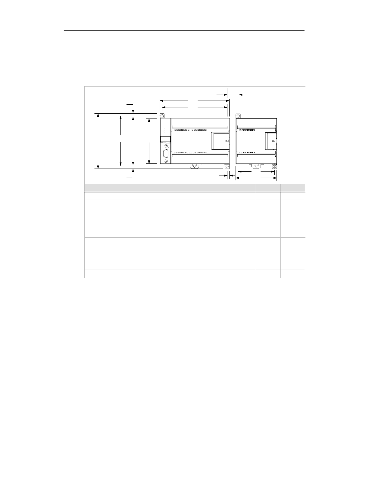
The S7-200 CPUs and expansion modules include mounting holes to facilitate installation on
panels. RefertoTable 3-1 for the mountingdimensions.
Table 3-1 Mounting Dimensions
96 mm
Mounting
holes (M4
or No. 8)
A
B
4mm
88 mm 80 mm
9.5 mm*
4mm
4mm
* Minimum spacing
between modules
when hard-mounted
B
A
S7-200 Module Width A Width B
CPU 221 and CPU 222 90 mm 82 mm
CPU 224 120.5 mm 112.5 mm
CPU 224XP,CPU 224XPsi 140 mm 132 mm
CPU 226 196 mm 188 mm
Expansion modules: 4- and 8-point DC and Relay I/O (8I, 4Q, 8Q, 4I/4Q)
and Analog Out (2 AQ)
46 mm 38 mm
Expansion modules: 16-point digital I/O (16I, 8I/8Q), Analog I/O (4AI, 8AI, 4AQ,
4AI/1AQ), RTD, Thermocouple, PROFIBUS, Ethernet,
Internet, AS-Interface, 8-point AC (8I and 8Q), Position, and
Modem
71.2 mm 63.2 mm
Expansion modules: 32-point digital I/O (16I/16Q) 137.3 mm 129.3 mm
Expansion modules: 64-point digital I/O (32I/32Q) 196mm 188 mm
Installing a CPU or Expansion Module
Installing the S7-200 is easy! Just follow these steps.
Panel Mounting
1. Locate, drill, and tap the mountingholes (M4 or American Standardnumber8), using the
dimensions in Table 3-1.
2. Secure the module(s)tothepanel,using the appropriate screws.
3. If you are using an expansion module, connect the expansion module ribboncable into the
expansion port connectorundertheaccess door.
DIN Rail Mounting
1. Secure the railtothemounting panel every 75 mm.
2. Snap open the DIN clip (located on the bottomofthemodule) and hook the back of the
module onto the DIN rail.
3. If you are using an expansion module, connect the expansion module ribboncable into the
expansion port connectorundertheaccess door.
4. Rotate the module down to the DIN railandsnap the clipclosed.Carefully check that the
clip has fastened the module securelyontotherail. To avoid damage to the module, press
on the tab of the mounting hole insteadofpressing directly on the frontofthemodule.
Page 33
Installing the S7-200 Chapter 3
19
Tip
Using DIN railstopscouldbe helpfulif your S7-200 is in an environment with high vibration
potentialorifthe S7-200 has been installed vertically.
If your system is in a high-vibration environment, then panel-mounting the S7-200 will provide a
greaterlevelofvibration protection.
Removing a CPU or Expansion Module
To remove an S7-200 CPU or expansion module,follow these steps:
1. Remove power from the S7-200.
2. Disconnect all the wiring and cabling thatisattached to the module.MostS7-200 CPU and
expansion modules have removable connectorstomake this job easier.
3. If you have expansion modules connected to the unit thatyou are removing, open the
access cover door and disconnect the expansion module ribbon cable fromthe adjacent
modules.
4. Unscrew the mounting screws or snap open the DIN clip.
5. Remove the module.
Removing and Reinstalling the Terminal Block Connector
Most S7-200 modules have removable connectorstomakeinstalling and replacing the module
easy.Refer to Appendix A to determine whether your S7-200 module has removable connectors.
You can order an optional fan-outconnectorfor modules that do not have removable connectors.
See Appendix E for order numbers.
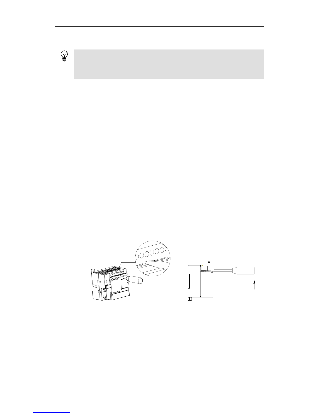
To Remove the Connector
1. Open the connector door to gain access to the connector.
2. Insert a smallscrewdriver in the notch in the middle of the connector.
3. Remove the terminalconnectorby prying the screwdriver away from the S7-200 housing.
SeeFigure3-2.
Figure 3-2 Removing the Connector
To Reinstall the Connector
1. Open the connector door.
2. Align the connector with the pins on the unit and align the wiring edge of the connector
inside the rimofthe connector base.
3. Press down firmlytorotate the connector until it snaps into place. Check carefully to ensure
that the connectorisproperly aligned and fully engaged.
Page 34

S7-200 Programmable Controller System Manual
20
Guidelines for Grounding and Wiring
Proper groundingand wiring of all electricalequipment is important to help ensure the optimum
operation ofyoursystemand toprovide additional electrical noise protection for your application
and the S7-200.
Prerequisites
Before you ground or installwiring to any electrical device, ensure thatthepowertothat
equipment has been turned off. Also, ensure thatthepowertoany related equipmenthas been
turned off.
Ensure that you followallapplicable electrical codes when wiringtheS7-200and related
equipment.Install and operate allequipmentaccording to all applicable national and local
standards. Contactyourlocal authorities to determinewhichcodes and standards apply to your
specific case.
Warning
Attemptstoinstall or wiretheS7-200orrelated equipment with power applied could cause
electricshock or faulty operation of equipment. Failure to disableallpowerto the S7-200 and
related equipmentduring installation or removalprocedures could resultin death or serious
injury to personnel,and/or damage to equipment.
Always follow appropriate safety precautions and ensure that power to theS7-200isdisabled
before attempting to install or remove the S7-200 or relatedequipment.
Always take safety into consideration as you design the grounding and wiringofyourS7-200
system. Electronic control devices, such as the S7-200, can fail and can cause unexpected
operation oftheequipmentthat is being controlled or monitored.Forthis reason, you should
implementsafeguards thatareindependentofthe S7-200 to protectagainst possible personal
injury or equipmentdamage.
Warning
Control devices can failinanunsafecondition, resulting in unexpected operation of controlled
equipment.Such unexpected operations could resultin death or serious injurytopersonnel,
and/or damage to equipment.
Use an emergency stop function, electromechanical overrides, or other redundantsafeguards
that are independentoftheS7-200.
Guidelines for Isolation
S7-200 AC power supply boundaries and I/O boundariestoAC circuits have been designed and
approved to provide safe separation between AC line voltages and low voltage circuits. These
boundaries include double orreinforced insulation, or basic plus supplementary insulation,
according to variousstandards. Components which cross these boundaries such as optical
couplers, capacitors, transformers,and relayshave been approved as providingsafeseparation.
Isolationboundaries which meet theserequirements have been identified in S7-200 product data
sheets as having 1500VACorgreater isolation. This designation is based on a routine factory test
of ( 2Ue + 1000VAC)orequivalent according to approved methods. S7-200 safe separation
boundaries have been type tested to 4242 VDC.
The sensor supply output, communications circuits, and internal logic circuits of an S7-200 with
included AC power supply are sourced as SELV (safety extra--low voltage)according to EN
61131--2. These circuits become PELV(protective extra--low voltage) if the sensor supply M,or
any other non-isolatedMconnection to the S7-200 is connected to ground.Other S7-200 M
connections which may ground referencethelowvoltage are designated as not isolatedtologic
on specific productdatasheets.Examples are RS485 communications port M, analog I/OM,and
relay coil power M.
To maintain the SELV /PELV character of the S7-200 low voltage circuits, external connections to
communicationsports, analog circuits, and all 24V nominal power supply and I/O circuits must be
powered from approved sources thatmeetthe requirementsofSELV,PELV,Class2,Limited
Voltage, or Limited Power according to various standards.
Page 35

Installing the S7-200 Chapter 3
21
Warning
Use of non-isolatedorsingle insulation suppliestosupplylowvoltage circuitsfrom an AC line
can result in hazardous voltagesappearing on circuits that are expected to be touch safe, such
as communications circuits and low voltage sensor wiring.
Such unexpected high voltages could resultindeathorserious injury to personnel, and/or
damage to equipment.
Only use high voltage to low voltage powerconverters that are approved as sources of touch
safe, limited voltage circuits.
Guidelines for Grounding the S7-200
The best way to ground your application is to ensurethatall the common and ground connections
of your S7-200 and related equipmentare grounded to a single point. This singlepointshould be
connected directly to the earth ground foryoursystem.
For improved electrical noise protection, itisrecommended that all DC common returnsbe
connected to the same single-pointearth ground. Connect the 24 VDC sensor supply common
(M) to earthground.
All ground wires should be as short as possible and should use a large wire size, such as 2 mm
2
(14 AWG).
When locating grounds,remember to consider safetygrounding requirements and the proper
operation ofprotective interrupting devices.
Guidelines for Wiring the S7-200
When designing the wiringfor your S7-200, providea singledisconnectswitch that simultaneously
removes power from theS7-200CPU powersupply, from all inputcircuits, and fromalloutput
circuits.Provide overcurrent protection, such as a fuse or circuitbreaker,to limit fault currents on
supply wiring.You might want to provide additionalprotection by placing a fuse or other current
limitin each output circuit.
Installappropriate surge suppression devices for any wiring that couldbe subjecttolightning
surges.
Avoid placinglow-voltage signal wiresand communications cables in the same wiretray withAC
wires and high-energy, rapidly switched DC wires.Always routewires in pairs, withtheneutral or
common wire pairedwith the hot or signal-carrying wire.
Use the shortest wirepossible and ensure that the wireissizedproperly to carry the required
current.Theconnectoraccepts wiresizesfrom 2 mm
2
to 0.3 mm2(14 AWG to 22 AWG). Use
shielded wires foroptimum protection againstelectrical noise.Typically,grounding the shield at
the S7-200 gives the best results.
When wiring inputcirc uits that are powered by an external power supply, include an overcurrent
protectiondeviceinthat circuit.External protection is not necessary forcircuits that arepowered
by the 24 VDC sensor supply from the S7-200 because the sensor supply is already
current-limited.
Most S7-200 modules have removable connectorsforuser wiring. (Refer to Appendix A to
determineifyourmodule has removable connectors.)To prevent loose connections,ensurethat
the connector is seated securelyand thatthewire is installed securely intotheconnector. To avoid
damaging the connector, be careful that you do not over-tighten the screws.Themaximumtorque
for the connectorscrewis0.56N-m (5 inch-pounds).
To help prevent unwanted current flows in your installation, the S7-200 provides isolation
boundaries at certainpoints. When you plan the wiring foryoursystem, you should consider these
isolationboundaries. Refer to Appendix A for the amount of isolation providedandthelocation of
the isolationboundaries. Isolation boundaries rated less than 1500 VACmustnotbe depended on
as safety boundaries.
Tip
For a communications network,the maximum length of the communications cable is 50 m
without using a repeater. The communications port on the S7-200 is non-isolated. Refer to
Chapter 7 for more information.
Page 36
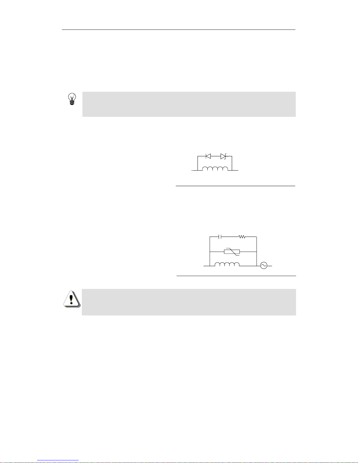
S7-200 Programmable Controller System Manual
22
Guidelines for Inductive Loads
You should equip inductive loads withsuppression circuits to limit voltagerise when the control
output turnsoff. Suppression circuits protectyouroutputs from premature failureduetohigh
inductive switching currents. In addition, suppression circuits limit the electrical noise generated
when switching inductiveloads.
Tip
The effectiveness of a given suppression circuitdepends on the application, and you must verify
it foryourparticular use. Always ensure that all components used in your suppression circuit are
rated foruse in the application.
DC Outputs and Relays That Control DC Loads
The DC outputs have internal protection that is adequate for most applications.Since the relays
can be used for either a DC or an AC load, internalprotection is not provided.
Figure 3-3 shows a sample suppression
circuitfora DC load. Inmost
applications,the additionofadiode(A)
across the inductiveloadissuitable, but
if your application requires fasterturn-off
times,thentheaddition of a Zener diode
(B) is recommended.Besuretosize
A -- I1N4001 diode orequivalent
B -- 8.2 V Zenerfor DCOutputs
36 VZener forRelay Outputs
A
DC Inductive Load
B (optional)
Output
Point
yourZener
d
iod
e properlyfor
t
h
e amoun
t
of currentinyouroutputcircuit.
Figure 3-3 Suppression Circuit for a DC Load
AC Outputs and Relays That Control AC Loads
The AC outputs have internal protection that is adequate for most applications.Since the relays
can be used for either a DC or an AC load, internalprotection is not provided.
Figure 3-4 shows a sample suppression
circuitforan AC load. When you use a
relay or AC output to switch115 V/230
VAC loads, place resistor/capacitor
networks across the AC load as shown
in this figure. You can also use a metal
oxide varistor(MOV) to limitpeak
voltage. Ensurethatthe working voltage
of the MOV is at least 20%
g
reaterthan
MOV
AC Inductive Load
Output
Point
.1 µ F 100 to 120 Ω
oftheMOVisatleast20%greaterthan
the nominal linevoltage.
Figure 3-4 Suppression Circuit for an AC Load
Warning
When relay expansion modules are used to switch AC inductiveloads,the external
resistor/capacitornoisesuppression circuitmustbeplacedacrossthe AC load to prevent
unexpected machine or process operation.See Figure3-4.
Guidelines for Lamp Loads
Lamp loads are damaging to relay contactsbecause of the high turn-on surge current. This surge
currentwillnominally be 10 to 15 times the steady state current for a Tungstenlamp. A
replaceable interposing relay or surge limiter is recommendedforlamp loads that will be switched
a large number of timesduring the lifetime of the application.
Page 37

23
PLC Concepts
The basic function of the S7-200 is to monitor fieldinputs and, based on your control logic, turnon
or offfield output devices. This chapter explains the concepts used to execute your program,the
various types of memory used, and how that memoryisretained.
In This Chapter
Understanding How the S7-200 Executes Your Control Logic 24..........................
Accessing the Data of the S7-200 27..................................................
Understanding How the S7-200 Saves and Restores Data 36.............................
Selecting the Operating Mode for the S7-200 CPU 40....................................
Using the S7-200 Explorer 41........................................................
Features of the S7-200 41...........................................................
Page 38
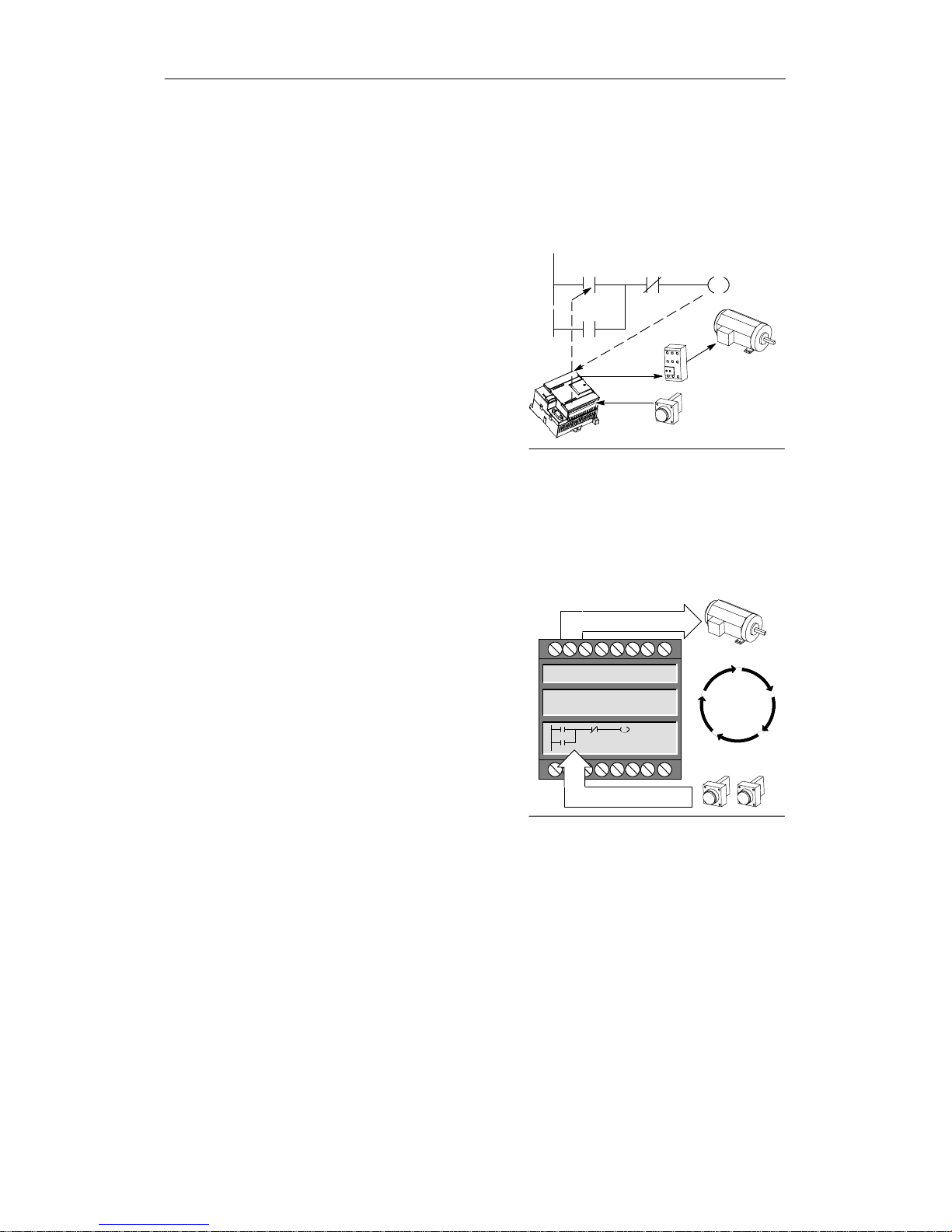
S7-200 Programmable Controller System Manual
24
Understanding How the S7-200 Executes Your Control Logic
The S7-200 continuously cycles throughthecontrol logic in your program, reading and writing
data.
The S7-200 Relates Your Program to the Physical Inputs and Outputs
The basic operation of the S7-200 is very simple:
- The S7-200 reads the status of the inputs.
- The program that is storedinthe S7-200 uses
these inputs to evaluatethecontrol logic. As
the program runs,theS7-200updates the
data.
- The S7-200 writes the data to the outputs.
Figure 4-1 shows a simple diagramofhow an
electricalrelay diagram relates to the S7-200. In this
example, the stateoftheswitch forstarting the
motor is combined withthestates of otherinputs.
The calculations of thesestatesthen determine the
Start_PB
M_Starter
M_StarterE_Stop
Output
Motor
Start /Stop Switch
Input
Motor Starter
Thecalculationsofthesestatesthendetermineth
e
state fortheoutputthat goes to the actuatorwhich
startsthemotor.
Figure 4-1 Controlling Inputs and Outputs
The S7-200 Executes Its Tasks in a Scan Cycle
The S7-200 executes a series of tasks repetitively. This cyclical execution of tasks is called the
scan cycle. As shown in Figure 4-2, the S7-200 performs most orallofthe following tasks duringa
scan cycle:
- Reading the inputs:The S7-200 copies the
state of the physicalinputs to the
process-imageinputregister.
- Executing the controllogic in the program:
The S7-200 executes the instructions of the
program and stores the values in the various
memory areas.
- Processing any communicationsrequests:
The S7-200 performs any tasks required for
communications.
- Executing the CPU self-test diagnostics:The
S7-200 ensures that the firmware, the
program memory, and any expansion
modules are working properly.
Writes to the outputs
Process any
Communications Requests
Perform the CPU Diagnostics
Scan Cycle
Reads theinputs
Execute the Program
- Writing to the outputs: The values stored in
the process-imageoutputregister are written
to the physical outputs.
Figure 4-2 S7-200 Scan Cycle
The execution of the user programisdependentupon whethertheS7-200is in STOP mode or in
RUN mode. In RUN mode, your program is executed;inSTOPmode,yourprogram is not
executed.
Page 39

PLC Concepts Chapter 4
25
Reading the Inputs
Digitalinputs: Each scan cycle begins by reading the currentvalueofthe digital inputsand then
writingthesevaluestothe process-image inputregister.
Analog inputs: The S7-200 does not update analog inputs fromexpansion modules as part of the
normal scan cycle unless filtering of analog inputs is enabled. An analog filterisprovided to allow
you to have a more stable signal. You can enable the analog filter foreach analog inputpoint.
When analog input filtering is enabled foran analog input,the S7-200 updates thatanaloginput
once per scan cycle, performsthefiltering function,and storesthefiltered value internally. The
filtered value is then suppliedeach timeyourprogram accesses the analog input.
When analog filtering is not enabled, the S7-200 reads the value of theanaloginputfrom
expansion modules each time your programaccesses the analog input.
Analog inputs AIW0 and AIW2 includedon the CPU 224XP are updated every scan with the most
recent resultfrom the analog-to-digital converter. This converter is an averaging type (sigma-delta)
and those values will usually notneed software filtering.
Tip
Analog input filtering is provided to allow you to have a more stable analog value. Use the
analog input filter for applications where the input signalvaries slowly with time.If the signal is a
high-speed signal,then you should not enable the analog filter.
Do not use the analog filterwith modules thatpass digitalinformation or alarm indications in the
analog words. Always disable analog filtering for RTD, Thermocouple,andAS-Interface Master
modules.
Executing the Program
During the executionphase of the scan cycle, theS7-200executesyourprogram, starting with the
firstinstruction and proceeding to the end instruction.The immediate I/Oinstructions give you
immediateaccess to inputsand outputsduring the execution of eitherthe program or an interrupt
routine.
If you use subroutines in your program, the subroutinesarestored as part of the program.The
subroutines areexecutedwhen they are calledby the mainprogram, by anothersubroutine, or by
an interruptroutine. Subroutine nestingdepthis8 fromthe main and 1 from an interruptroutine.
If you use interrupts in your program, the interrupt routines that are associated withthe interrupt
events are stored as part of the program. The interruptroutines are not executed as part of the
normal scan cycle, but areexecutedwhen theinterrupt eventoccurs(which could be at any point
in the scan cycle).
Local memory is reservedforeachofelevenentities:onemain,eight subroutine nesting levels
when initiatedfrom the main, one interrupt, and one subroutinenesting level when initiated from
an interruptroutine. Local memoryhas a local scope in thatitis availableonlywithin its
associated programentity, and cannot be accessed by the other program entities. For more
information about Local memory, refer to Local Memory Area: L in this chapter.
Figure 4-3 depictstheflow of a typical scan including the Local memoryusage and two interrupt
events, one during the program--execution phase and anotherduring the communications phase
of the scan cycle. Subroutinesarecalled by the next higher level,andareexecutedwhencalled.
Interrupt routines arenotcalled; they are a result of an occurrenceoftheassociated interrupt
event.
Page 40
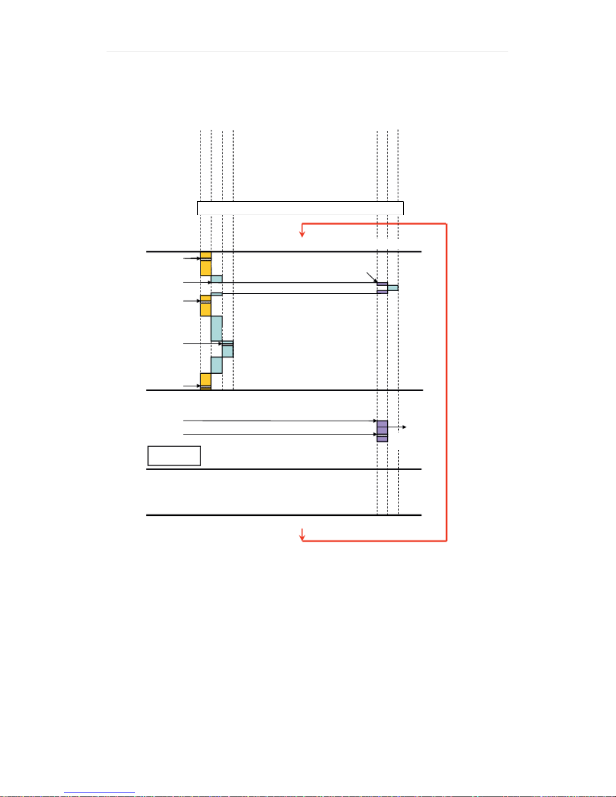
S7-200 Programmable Controller System Manual
26
Reading inputs toprocess imageinputregister
Communication
Self-test diagn ostics
Subroutine
Main Program
Subroutine
Main Program
Subroutine
Subroutine
Main
SBR nesting Level 1
SBR nesting level 2
Interrupt
Local (L) Memory
SBR nestinglevel 3
SBR nesting level 4
SBR nesting level 5
SBR nesting level 6
SBR nesting level 7
SBR nesting level 8
Max 64 bytes data for each entity level
. Interrupt
SBR nesting level 1
Event
Main Program
Subroutine
SI Q0.0
Event
Immediate I/O
operations
HMI, EM277, Status Chart, PC accessٛ
1ms*
1ms*
1ms*
1ms*
1ms*
* Internal 1ms
Timer Update
Writing from process image to the outputs
S7-200 ensures that thef irmware, the program memory, and any
expansio n modules areworking properly
Cycle Time
Figure 4-3 Typical Scan Flow
Page 41
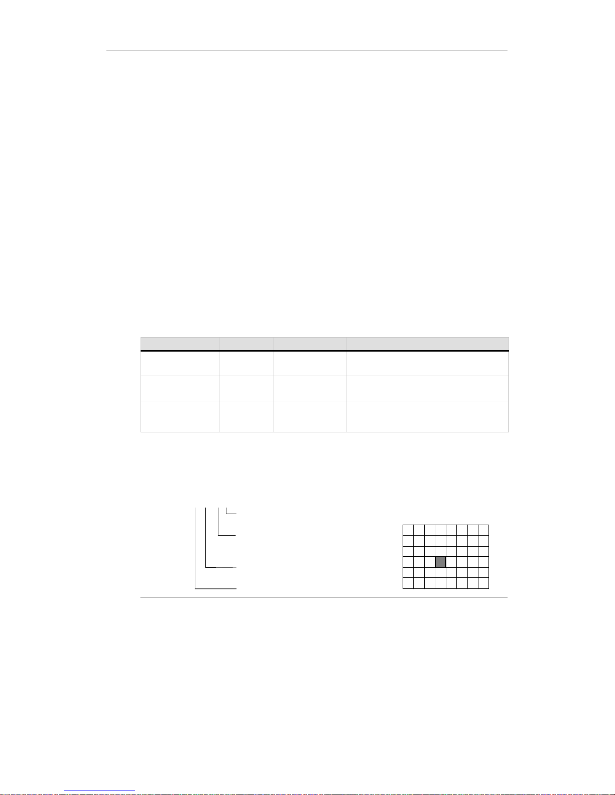
PLC Concepts Chapter 4
27
Processing Any Communications Requests
During the message-processing phase of the scan cycle, the S7-200 processes any messages
that were receivedfrom the communications portorintelligent I/O modules.
Executing the CPU Self-test Diagnostics
During this phase of the scan cycle, the S7-200checks forproperoperation of the CPU and for
the status of any expansion modules.
Writing to the Digital Outputs
At the end of every scan cycle, the S7-200 writesthevaluesstored in the process-image output
registerto the digital outputs.(Analog outputs are updated immediately, independently fromthe
scan cycle.)
Accessing the Data of the S7-200
The S7-200 stores information in different memorylocations that have unique addresses. You can
explicitly identify the memoryaddressthatyouwanttoaccess.This allows your program to have
direct access to the information.Table 4-1 shows the range of integer values thatcan be
representedby the different sizes of data.
Table 4-1 Decimal and Hexadecimal Ranges for the Different Sizes of Data
Representation Byte (B) Word (W) Double Word (D)
Unsigned Integer 0to255
0toFF
0 to 65,535
0 to FFFF
0 to 4,294,967,295
0 to FFFF FFFF
Signed Integer --128 to +127
80 to 7F
--32,768 to +32,767
8000 to 7FFF
--2,147,483,648 to +2,147,483,647
8000 0000 to 7FFF FFFF
Real
IEEE 32-bit
Floating Point
Not applicable Not applicable +1.175495E--38 to +3.402823E+38 (positive)
--1.175495E--38 to --3.402823E+38 (negative)
To access a bit in a memory area,you specifytheaddress, which includes the memory area
identifier, the byte address, and the bitnumber. Figure 4-4 shows an example of accessing a bit
(which is also called“byte.bit” addressing).Inthis example,thememory area and byte address
(I = input,and 3 = byte 3) are followedby a period (“.”) to separate the bit address (bit4).
I3 4
76543210
Byte 0
Byte 1
Byte 2
Byte 3
Byte 4
Byte 5
.
Memory area identifier
Byte address: byte 3 (the
fourth byte)
Period separates the
byte address from the bit
number
Bit of byte, or bit number:
bit4of8(0to7)
Process-image Input (I) Memory Area
Figure 4-4 Byte.Bit Addressing
You can access data in most memory areas (V, I, Q, M, S, L, and SM) as bytes, words, or double
words by using the byte-address format. To access a byte,word,ordouble word of data in the
memory, you must specify the address in a way similar to specifyingtheaddress for a bit. This
includes an area identifier, data size designation, and the starting byte address of the byte,word,
or double-wordvalue,asshown in Figure4-5.
Page 42

S7-200 Programmable Controller System Manual
28
Data in other memoryareas(suchas T, C, HC, and the accumulators) areaccessed by using an
address formatthatincludes an area identifier and a device number.
V B 100
VB100
MSB
LSB
VW100
15 8
MSB
70
LSB
VD100
Most significant byte Least significant byte
31 87 016 1524 23
Most significant byte Least significant byte
MSB = most significant bit
LSB = least significant bit
VB100
VB100 VB101
VB100 VB103VB101 VB102
MSB LSB
70
Byte address
Access to a byte size
Area identifier
V W 100
Byte address
Access to a word size
Area identifier
V D 100
Byte address
Access to a double wordsize
Area identifier
Figure 4-5 Comparing Byte, Word, and Double-Word Access to the Same Address
Accessing Data in the Memory Areas
Process-Image Input Register: I
The S7-200 samples the physical input pointsatthe beginning of each scan cycle and writes
these values to the process-image input register. You can access the process-image input register
in bits, bytes,words, or double words:
Bit: I[byteaddress].[bit address] I0.1
Byte, Word,or Double Word: I[size][starting byte address] IB4
Process-Image Output Register: Q
At the end of the scan cycle, the S7-200 copies the values stored in the process-image output
registerto the physical output points.You can access the process-image output register in bits,
bytes, words,ordoublewords:
Bit: Q[byte address].[bit address] Q1.1
Byte, Word,or Double Word: Q[size][starting byte address] QB5
Variable Memory Area: V
You can use V memory to store intermediate results of operationsbeingperformed by the control
logic in your program.You can also use V memory to store other data pertainingtoyourprocess
or task. You can access the V memory area in bits,bytes, words, or double words:
Bit: V[byte address].[bit address] V10.2
Byte, Word,or Double Word: V[size][starting byte address] VW100
Bit Memory Area: M
You can use the bit memory area (M memory)as controlrelays to store the intermediate statusof
an operation or othercontrol information. You can access the bit memoryareainbits, bytes,
words, or double words:
Bit: M[byte address].[bit address] M26.7
Byte, Word,or Double Word: M[size][starting byte address] MD20
Page 43
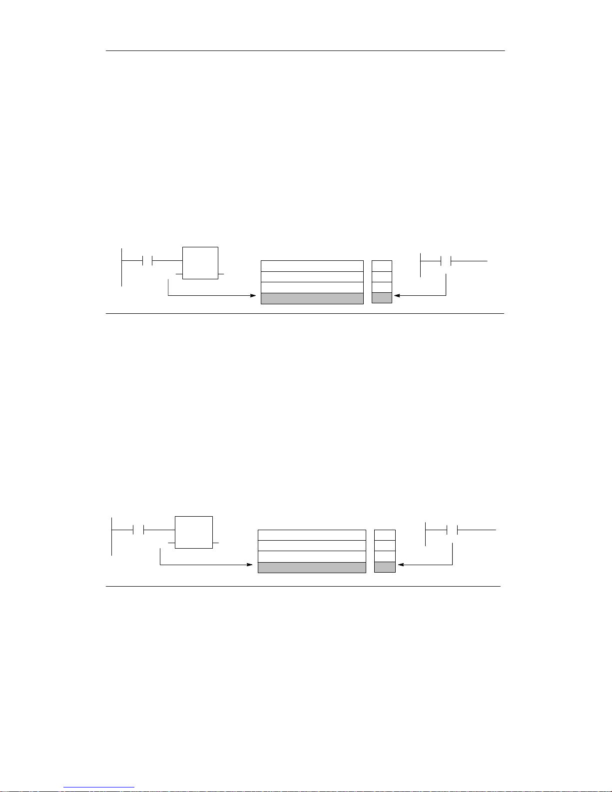
PLC Concepts Chapter 4
29
Timer Memory Area: T
The S7-200 provides timersthatcount increments of time in resolutions (time-baseincrements) of
1 ms, 10 ms, or 100 ms. Two variablesareassociated witha timer:
- Currentvalue:this 16-bit signed integerstores the amount of time counted by the timer.
- Timerbit: this bit is set or cleared as a result of comparing the currentand the presetvalue.
The preset value is entered as part of the timer instruction.
You access both of these variables by using the timeraddress(T + timer number).Accessto
either thetimer bit or the currentvalue is dependent on the instruction used: instructions withbit
operands access the timer bit,while instructions with word operands access the currentvalue.As
shown in Figure 4-6, the Normally Open Contact instruction accesses the timer bit,while the Move
Wordinstructionaccesses the currentvalue of the timer.
Format: T[timernumber] T24
Current Value
T0
T1
T2
T3
I2.1
MOV_
W
EN
OUT VW200INT3
T3
Timer Bits
T0
T3
T1
T2
0 (LSB)15 (MSB)
Accessesthe currentvalue
Accessesthe timerbit
Figure 4-6 Accessing the Timer Bit or the Current Value of aTimer
Counter Memory Area: C
The S7-200 provides three types of countersthatcount each low-to-high transition event on the
counter input(s): one type counts up only, one type counts down only,andone type countsboth
up and down. Two variablesareassociated with a counter:
- Currentvalue:this 16-bit signed integerstores the accumulated count.
- Counter bit:this bit is set or clearedas a resultofcomparing the currentand the preset
value. The preset value is enteredas partofthecounter instruction.
You access both of these variables by using the counter address (C + counter number). Access to
either thecounterbit or the currentvalueisdependenton theinstruction used: instructions with bit
operands access the counter bit,while instructionswith word operands access the currentvalue.
As shown in Figure 4-7, the NormallyOpenContactinstructionaccessesthecounterbit, while the
Move Word instruction accesses the current value of the counter.
Format: C[counternumber] C24
Current Value
C0
C1
C2
C3
I2.1
MOV_W
EN
OUT VW200INC3
C3
Counter Bits
C0
C3
C1
C2
0 (LSB)15 (MSB)
Accesses the current value Accesses the counter bit
Figure 4-7 Accessing the Counter Bit or the Current Value of a Counter
Page 44
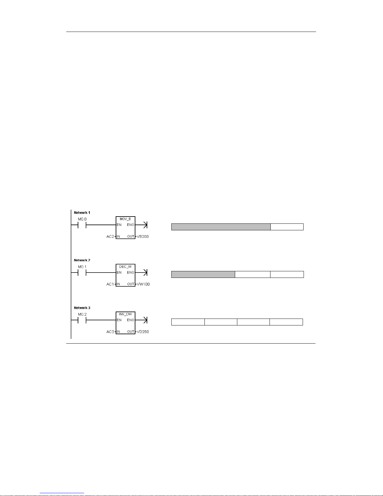
S7-200 Programmable Controller System Manual
30
High-Speed Counters: HC
The high-speed counters count high-speedeventsindependentofthe CPU scan. High-speed
counters have a signed, 32-bitinteger counting value (orcurrent value). Toaccess thecount
value for the high-speedcounter, you specify the address of the high-speed counter, using the
memory type (HC) and the counternumber(suchas HC0).The currentvalue of the high-speed
counter is a read-onlyvalueand can be addressed only as a double word (32 bits).
Format: HC[high-speedcounternumber] HC1
Accumulators: AC
The accumulators are read/write devices that can be used likememory. For example, you can use
accumulatorstopass parameters to and fromsubroutines and to store intermediate values used
in a calculation.The S7-200provides four 32-bitaccumulators (AC0, AC1, AC2, and AC3).You
can access the data in the accumulators as bytes, words,ordouble words.
The size of the data being accessed is determined by the instruction that is used to access the
accumulator. As shown in Figure 4-8, you use the least significant 8 or 16 bits of the value thatis
stored in the accumulator to access the accumulatorasbytesorwords. To access the
accumulatoras a double word,you use all 32 bits.
For information about how to use the accumulators within interrupt subroutines, refer to the
InterruptInstructions in Chapter 6.
Format: AC[accumulatornumber] AC0
MSB
70
LSB
15 0
LSB
31
MSB
0
LSB
AC2 (accessed as a byte)
AC1 (accessed as a word)
MSB
78
7815162324
Least significant
Least significantMost significant
Byte 0Byte 1
Byte 0Byte 1Byte 2Byte 3
Most significant
AC3 (accessed as a double word)
Figure 4-8 Accessing the Accumulators
Page 45

PLC Concepts Chapter 4
31
Special Memory: SM
The SM bits provide a means for communicatinginformation between the CPU and your program.
You can use these bits to select and control some of the special functions of the S7-200 CPU,
such as: a bit that turns on forthefirst scan cycle, a bit that toggles at a fixed rate,orabitthat
shows the status of math or operational instructions. (For more informationabouttheSMbits, see
Appendix D.) You can access the SM bits as bits,bytes,words, or double words:
Bit: SM[byte address].[bit address] SM0.1
Byte, Word,or Double Word: SM[size][starting byte address] SMB86
Local Memory Area: L
The S7-200 provides 64 bytes of local memory of which 60 can be used as scratchpad memory or
for passing formalparameters to subroutines.
Tip
If you are programming in either LAD or FBD, STEP 7--Micro/WINreserves the lastfourbytes of
local memory forits own use.
Local memory is similarto V memorywith one major exception. V memory has a global scope
while L memory has a local scope. The term global scope means that the same memorylocation
can be accessed from any program entity (mainprogram, subroutines, or interrupt routines).The
term localscope means thatthememory allocation is associatedwith a particular program entity.
The S7-200 allocates 64 bytes of L memory for the mainprogram, 64 bytes foreach subroutine
nesting level,and64 bytes forinterrupt routines.
The allocation ofL memoryforthe main program cannot be accessed from subroutines or from
interruptroutines. A subroutine cannot access the L memory allocationofthemain program,an
interruptroutine, or another subroutine.Likewise, an interrupt routinecannotaccess the L memory
allocationofthemain programorofa subroutine.
The allocation of L memory is made by the S7-200 on an as-needed basis. This means that while
the main portionoftheprogram is being executed, the L memory allocations for subroutines and
interruptroutines do not exist. At the time thatan interrupt occurs or a subroutineiscalled, local
memory is allocatedas required. The new allocation of L memory mightreusethesameL
memory locationsofa different subroutine or interrupt routine.
The L memory is not initialized by the S7-200 at the time of allocation and might containany
value. When you pass formal parameters in a subroutinecall, the values of the parametersbeing
passed are placed by the S7-200 in the appropriateLmemory locationsofthe called subroutine.L
memory locations,which do not receivea value as a resultoftheformal parameter passing step,
will not be initialized and might contain any value at the time of allocation.
Bit: L[byte address].[bit address] L0.0
Byte, Word,or Double Word: L[size] [starting byte address] LB33
Analog Inputs: AI
The S7-200 converts an analog value (such as temperatureorvoltage) into a word-length (16-bit)
digitalvalue.You access these values by the area identifier(AI), size of the data (W), and the
startingbyteaddress. Since analog inputs are words and always starton even-numberbytes
(such as 0, 2, or 4), you access them with even-numberbyteaddresses(suchas AIW0,AIW2, or
AIW4).Analoginputvalues are read-only values.
Format: AIW[starting byte address] AIW4
Page 46

S7-200 Programmable Controller System Manual
32
Analog Outputs: AQ
The S7-200 converts a word-length(16-bit)digital value into a current or voltage, proportional to
the digitalvalue(such as for a current or voltage).You write these values by the area identifier
(AQ),sizeofthedata(W), and the starting byte address. Since analog outputs arewordsand
always start on even-numberbytes(suchas0,2,or4),y ou write them with even-numberbyte
addresses (such as AQW0, AQW2, or AQW4).Analog output values are write-only v alues.
Format: AQW[starting byte address] AQW4
Sequence Control Relay (SCR) Memory Area: S
SCRs or S bits are used to organize machine operationsorstepsinto equivalentprogram
segments. SCRs allow logicalsegmentation of the control program.You can access the S bits as
bits, bytes,words, or double words.
Bit: S[byte address].[bit address] S3.1
Byte, Word,or Double Word: S[size][starting byte address] SB4
Format for Real Numbers
Real (or floating-point)numbers are represented as 32-bit, single-precision numbers, whose
formatisdescribed in the ANSI/IEEE 754--1985 standard. See Figure 4-9. Real numbers are
accessed in double-word lengths.
For the S7-200, floating point numbers are
accurate up to 6 decimal places.Therefore,
you can specify a maximum of 6 decimal
places when entering a floating-point
31 0
LSBMSB
2223
MantissaExponent
30
S
Sign
pgg
p
constant.
Figure 4-9 Format of a Real Number
Accuracy when Calculating Real Numbers
Calculationsthatinvolve a long seriesofvaluesincluding very large and very small numbers can
produce inaccurateresults. This can occur if the numbersdiffer by 10 to the power of x,
where x >6.
For example: 100 000 000 + 1 = 100 000 000
Format for Strings
A string is a sequence of characters,with each character being storedas a byte.The first byte of
the string definesthelength of the string, which is the number of characters. Figure 4-10 shows
the formatfora string.A string can have a length of 0 to 254 characters, plus the length byte, so
the maximum lengthforastring is 255 bytes.Astring constant is limited to 126 bytes.
Character 1
Byte 3Byte 2Byte 1Byte 0
Length Character 2 Character 3
Byte 4
Character 4
Byte 254
Character 254
...
Figure 4-10 Format for Strings
Page 47
PLC Concepts Chapter 4
33
Specifying a Constant Value for S7-200 Instructions
You can use a constant value in many of the S7-200 instructions.Constants can be bytes, words,
or double words. The S7-200 storesallconstants as binary numbers,whichcanthenbe
representedindecimal, hexadecimal,ASCII, or real number (floating point)formats. See
Table 4-2.
Table 4-2 Representation of Constant Values
Representation Format Sample
Decimal [decimal value] 20047
Hexadecimal 16#[hexadecimal value] 16#4E4F
Binary 2#[binary number] 2#1010_0101_1010_0101
ASCII ’[ASCII text]’ ’ABCD’
Real ANSI/IEEE 754--1985 +1.175495E--38 (positive) --1.175495E--38 (negative)
String “[stringtext]” “ABCDE”
Tip
The S7-200 CPU does not support “data typing”ordatachecking(suchas specifying thatthe
constant is storedas an integer, a signed integer,oradoubleinteger).Forexample,an Add
instruction can use the value in VW100 as a signed integer value, whilean ExclusiveOr
instruction can use the same value in VW100 as an unsigned binary value.
Addressing the Local and Expansion I/O
The local I/O providedby the CPU providesa fixedsetofI/O addresses.You can add I/O points to
the S7-200 CPU by connecting expansion I/O modules to the rightside of the CPU, forming an I/O
chain. The addresses of the points of the modulearedetermined by the type of I/Oandthe
position of themoduleinthechain,with respect to the preceding input or outputmoduleofthe
same type. For example,an outputmoduledoes notaffect the addresses of the points on an input
module, and vice versa. Likewise,analog modules do not affect the addressing of digital modules,
and vice versa.
Tip
Process-imageregister space for digital I/O is always reservedinincrements of eight bits (one
byte).Ifamoduledoesnotprovide a physical point for each bit ofeach reservedbyte,these
unused bits cannot be assigned to subsequent modules in the I/O chain.Forinput modules, the
unused bits are set to zero with each input updatecycle.
Analog I/O pointsarealwaysallocated in incrementsoftwopoints. If a module does not provide
physical I/Oforeachofthese points, these I/Opoints are lostand arenotavailable for
assignment to subsequent modules intheI/O chain.
Page 48
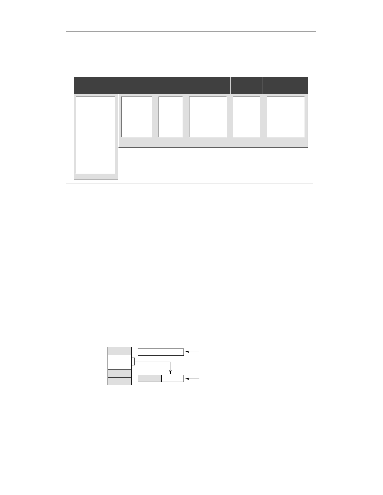
S7-200 Programmable Controller System Manual
34
Figure 4-11 provides an example of the I/O numbering for a particular hardware configuration.The
gaps in the addressing (shown as gray italictext) cannot be used by your program.
Module 0 Module 1 Module 2
I2.0 Q2.0
I2.1 Q2.1
I2.2 Q2.2
I2.3 Q2.3
I2.4 Q2.4
I2.5 Q2.5
I2.6 Q2.6
I2.7 Q2.7
I3.0
I3.1
I3.2
I3.3
I3.4
I3.5
I3.6
I3.7
CPU 224XP
4AnalogIn
1 Analog Out
8In4In/4Out
Module 3 Module 4
Q3.0
Q3.1
Q3.2
Q3.3
Q3.4
Q3.5
Q3.6
Q3.7
8Out
AIW4 AQW4
AIW6 AQW6
AIW8
AIW10
AIW12 AQW8
AIW14 AQW10
AIW16
AIW18
4AnalogIn
1 Analog Out
Expansion I/O
I0.0 Q0.0
I0.1 Q0.1
I0.2 Q0.2
I0.3 Q0.3
I0.4 Q0.4
I0.5 Q0.5
I0.6 Q0.6
I0.7 Q0.7
I1.0 Q1.0
I1.1 Q1.1
I1.2 Q1.2
I1.3 Q1.3
I1.4 Q1.4
I1.5 Q1.5
I1.6 Q1.6
I1.7 Q1.7
AIW0 AQW0
AIW2 AQW2
Local I/O
Figure 4-11 Sample I/O Addresses for Local and Expansion I/O (CPU 224XP)
Using Pointers for Indirect Addressing of the S7-200 Memory Areas
Indirectaddressing uses a pointer to access the data in memory. Pointers are double word
memory locationsthatcontain the address of another memory location. You can only use
V memory locations,Lmemory locations,oraccumulator registers (AC1, AC2, AC3) as pointers.
To create a pointer,you mustuse the Move Double Word instruction to move the address of the
indirectly addressed memorylocation to the pointerlocation. Pointers can also be passed to a
subroutine as a parameter.
The S7-200 allows pointers to access the following memory areas:I, Q, V, M, S, AI, AQ, SM,
T (currentvalue only), and C (current value only).You cannot use indirect addressing to access
an individual bitorto access HC or L memory areas.
To indirectly access the data in a memory address, you create a pointertothatlocation by
entering an ampersand (&)andthememory location to be addressed. The input operand ofthe
instruction must be preceded withan ampersand (&)to signifythatthe address of a memory
location,instead of itscontents, is to be moved into the locationidentified in theoutputoperand of
the instruction (thepointer).
Entering an asterisk (*) in frontofanoperandfor an instructionspecifies that the operandisa
pointer. As shown in Figure4-12,entering *AC1 specifiesthatAC1 is a pointertotheword-length
value being referencedby the Move Word (MOVW) instruction. Inthis example, the values stored
in both VB200 and VB201 are moved to accumulator AC0.
AC1
address of VW200
AC0
1234
12
34
56
78
V199
V200
V201
V202
V203
MOVD &VW200, AC1
MOVW *AC1, AC0
Creates the pointer by moving the address of VB200
(address of the initial byte for VW200) to AC1.
Moves the word value pointed to by AC1 to AC0.
Figure 4-12 Creating and Using a Pointer
Page 49
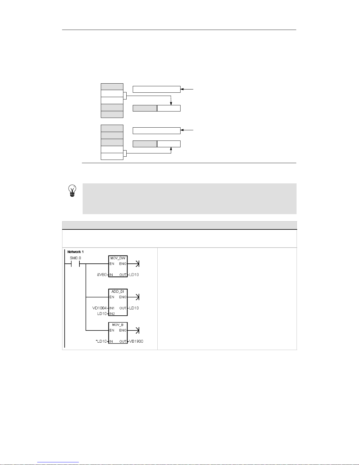
PLC Concepts Chapter 4
35
As shown in Figure 4-13, you can change the value of a pointer.Since pointersare 32-bit values,
use double-word instructions to modifypointer values. Simplemathematical operations, such as
adding or incrementing, can be used to modify pointervalues.
AC1
address of VW200
AC0
1234
12
34
56
78
V199
V200
V201
V202
V203
MOVD &VW200, AC1
MOVW *AC1, AC0
Creates the pointer by moving the address of
VB200 (address of VW200’s initial byte) to AC1.
Moves the word value pointed to by
AC1 (VW200) to AC0.
AC0
5678
12
34
56
78
V199
V200
V201
V202
V203
MOVW *AC1, AC0
Moves the word value pointed to by
AC1 (VW202) to AC0.
+D +2, AC1
AC1
address of VW202
Adds 2 to the accumulator to point to the
next word location.
Figure 4-13 Modifying a Pointer
Tip
Remember to adjustforthe size of the data thatyou areaccessing:to access a byte, increment
the pointervalueby 1; to access a word or a current valueforatimer or counter, add or
incrementthepointer value by 2; and to access a double word, add or incrementthepointer
value by 4.
Sample Program for Using an Offset to Access Data in V Memory
This example uses LD10 as a pointer to the address VB0. You then increment the pointer by an offset stored in VD1004.
LD10 then points to another address in V memory (VB0 + offset). The value stored in the V memory address pointed to
by LD10 is then copied to VB1900. By changing the value in VD1004, you can access any V memory location.
Network 1 //How to use an offset to read the value
//of any VB location:
//
//1. Load the starting address of the
//V memory to a pointer.
//2. Add the offset value to the pointer.
//3. Copy the value from the V memory
//location (offset) to VB1900.
//
LD SM0.0
MOVD &VB0, LD10
+D VD1004, LD10
MOVB *LD10, VB1900
Page 50
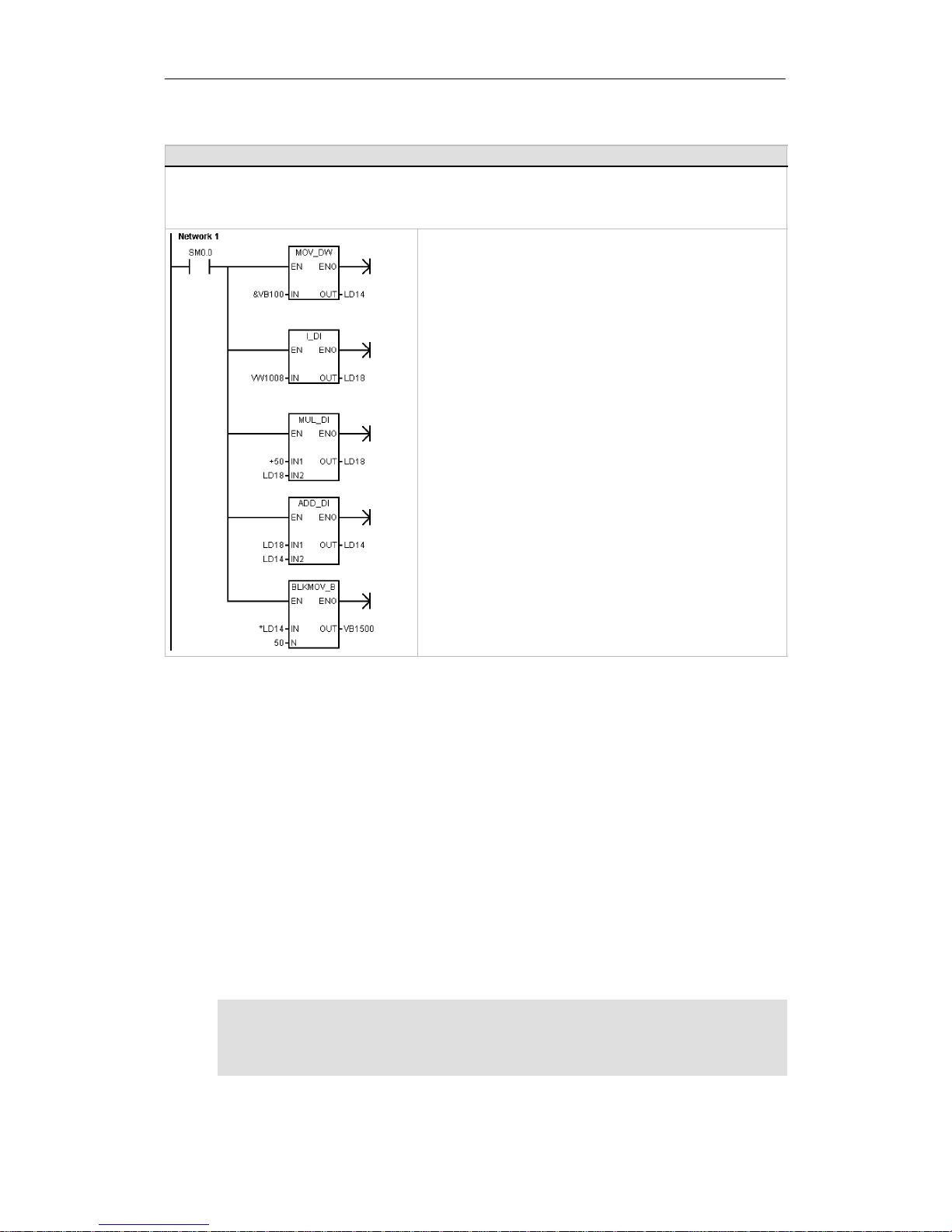
S7-200 Programmable Controller System Manual
36
Sample Program for Using a Pointer to Access Data in a Table
This example uses LD14 as a pointer to a recipe stored in a table of recipes that begins at VB100. In this example,
VW1008 stores the index to a specific recipe in the table. If each recipe in the table is 50 bytes long, you multiply the
index by 50 to obtain the offset for the starting address of a specific recipe. By adding the offset to the pointer, you can
access the individual recipe from the table. In this example, the recipe is copied to the 50 bytes that start at VB1500.
Network 1 //How to transfer a recipe from a table of recipes:
// -- Each recipe is 50 bytes long.
// -- The index parameter (VW1008) identifies
// the recipe to be loaded.
//
//1. Create a pointer to the starting address
// of the recipe table.
//2. Convert the index of the recipe to a
// double-word value.
//3. Multiply the offset to accommodate
// the size of each recipe.
//4. Add the adjusted offset to the pointer.
//5. Transfer the selected recipe to
// VB1500 through VB1549.
LD SM0.0
MOVD &VB100, LD14
ITD VW1008, LD18
*D +50, LD18
+D LD18, LD14
BMB *LD14, VB1500, 50
Understanding How the S7-200 Saves and Restores Data
The S7-200 provides a variety of features to ensure that your user program and data are properly
retained in theS7-200.
- Retentive DataMemory -- Areas of data memory the user selectstoremain unchanged
over a power cycle, as long as the super capacitor and the optionalbattery cartridge have
not been discharged. V, M, Timer Currents,and CounterCurrents are the only data memory
areas that are configurable to be retentive.
- Permanent Memory -- Non-volatile memory used to store the program block,data block,
system block, forcedvalues,M memoryconfigured to be saved on loss of power,and
selected values written under user programcontrol
- Memory Cartridge -- Removable non-volatilememory used to store the programblock,data
block, system block,recipes, data logs, and forced values
You can use the S7-200 Explorer to store documentation files(doc,text, pdf, etc.) intothe
cartridge.You can also use the S7-200 Explorer to performgeneral file maintenance on the
memory cartridge (copy, delete, directoryandlaunch).
To install a memory cartridge,remove the plastic slot cover from theS7-200CPU and insertthe
memory cartridge in the slot.Thememory cartridge is keyed for properinstallation.
Caution
Electrostatic discharge can damage the memory cartridge or the receptacleon the S7-200 CPU.
Make contact with a grounded conductivepad and/orweara groundedwrist strap when you
handle the cartridge. Store the cartridge in a conductive container.
Page 51

PLC Concepts Chapter 4
37
Downloading and Uploading the Elements of Your Project
Your projectconsistsofdifferent elements:
- Program block
- Data block (optional)
- System block (optional)
- Recipes (optional)
- Data log configurations (optional)
When you download a project, the programblock, data block and system block arestored in
permanent memoryforsafekeeping. Recipes and data log configurations are stored in the
memory cartridge, and replaceany existing recipes and data logs. Any program elementsnot
included in the download operation are left unchanged in permanentmemoryandthememory
cartridge.
If a project download includes recipes or
data log configurations, the memory
cartridge must remain installed for proper
program operation.
To download your project to an S7-200
CPU:
1. Select the File > Download menu
command.
2. Click each project elementyou
wish to download.
3. Click the Download Button.
Figure 4-14 Download a Project to S7-200 CPU
When you upload a project to your computer usingSTEP 7--Micro/WIN,the S7-200 uploads the
program block,datablockandsystemblockfrom permanent memory.Therecipes and data log
configurations are uploaded fromthememory cartridge. The data from the data logs is not
uploaded to your computer using STEP7--Micro/WIN.The S7-200 Exploreris used to upload the
data from the data logs (see Chapter14).
To upload your project from an S7-200
CPU:
1. Select the File > Upload menu
command.
2. Click each project elementthat you
wish to upload.
3. Click the Upload Button.
Figure 4-15 Upload a Project to the S7-200
Page 52

S7-200 Programmable Controller System Manual
38
Storing your Program on a Memory Cartridge
The S7-200 allows you to copy your user programfrom one CPU to another using a memory
cartridge.You can also distribute updates forany of the following blocks in your S7-200: the
program block,systemblock or data block.
Before copying any program elementsto the memory cartridge,STEP 7--Micro/WIN deletesall
program elements(including recipesand data logs)exceptfor user fileson the memorycartridge.
If your programwill not fit because of the size of your files, you can do one of two things to create
enough storage space for your program.You can either erase the memory cartridge using the
PLC > Erase Memory Cartridge menu command. Or, you can open the S7-200 Explorerand
remove user filesthatare no longer needed.
The PLC must be in STOP mode to program the memory cartridge.
To store your program in the memory
cartridge:
1. Select the PLC > Program
Memory Cartridge menu
command.
2. Click each project elementyou
wish to copy to the memory
cartridge(all programelements
that exist inyourproject are
selected by default). If the system
block is selected the forcevalues
will be copied as well.
3. Click the Program Button
Figure 4-16 Store a Program on a Memory Cartridge
The program block, systemblock,data block,and any forced values are copied from permanent
memory in the S7-200 to the memorycartridge. The recipes and data log configurations are
copied from STEP 7--Micro/WINtothememory cartridge.
Restoring a Program from a Memory Cartridge
To transfer the program froma memorycartridge to the S7-200, you must apply power to the
S7-200 with the memorycartridge installed. If any of the blocks or force values present in the
memory cartridge are different from the blocks or force values in the S7-200,then all blocks
present in the memorycartridge are copied to the S7-200.
- If a program block was transferred fromthememory cartridge, the program block in
permanent memoryisreplaced.
- If a data block was transferred fromthememory cartridge, the data block in permanent
memory is replaced,allofV memory is cleared,and V memory is initialized with the
contents of the data block.
- If a system block was transferred from the memory cartridge,the system block and force
values in the permanent memoryarereplaced and all retentive memory is cleared.
Once the transferred programhasbeen storedtopermanent memory you can remove the
memory cartridge. However, if recipes or data logs are present in the cartridge, you must leave
the memory cartridge installed. Leaving the memory cartridge installed will delay entry toRUN
mode on subsequent power cycles.
Notice
Powering on an S7-200 CPU with an installed memorycartridge that was programmedby a
different model of S7-200 CPU can cause an error. Memory cartridges that are programmedby
a lower model number CPU can be read by a higher model number CPU. However,the
opposite is not true.Forexample, memory cartridges that are programmed by a CPU 221 or
CPU 222 can be read by a CPU 224, but memory cartridges that are programmed by a
CPU 224 are rejected by a CPU 221 or CPU 222.
For a complete listofmemory cartridge usage restrictions, see Optional Cartridges(Memory
Cartridge)in Appendix A.
Page 53
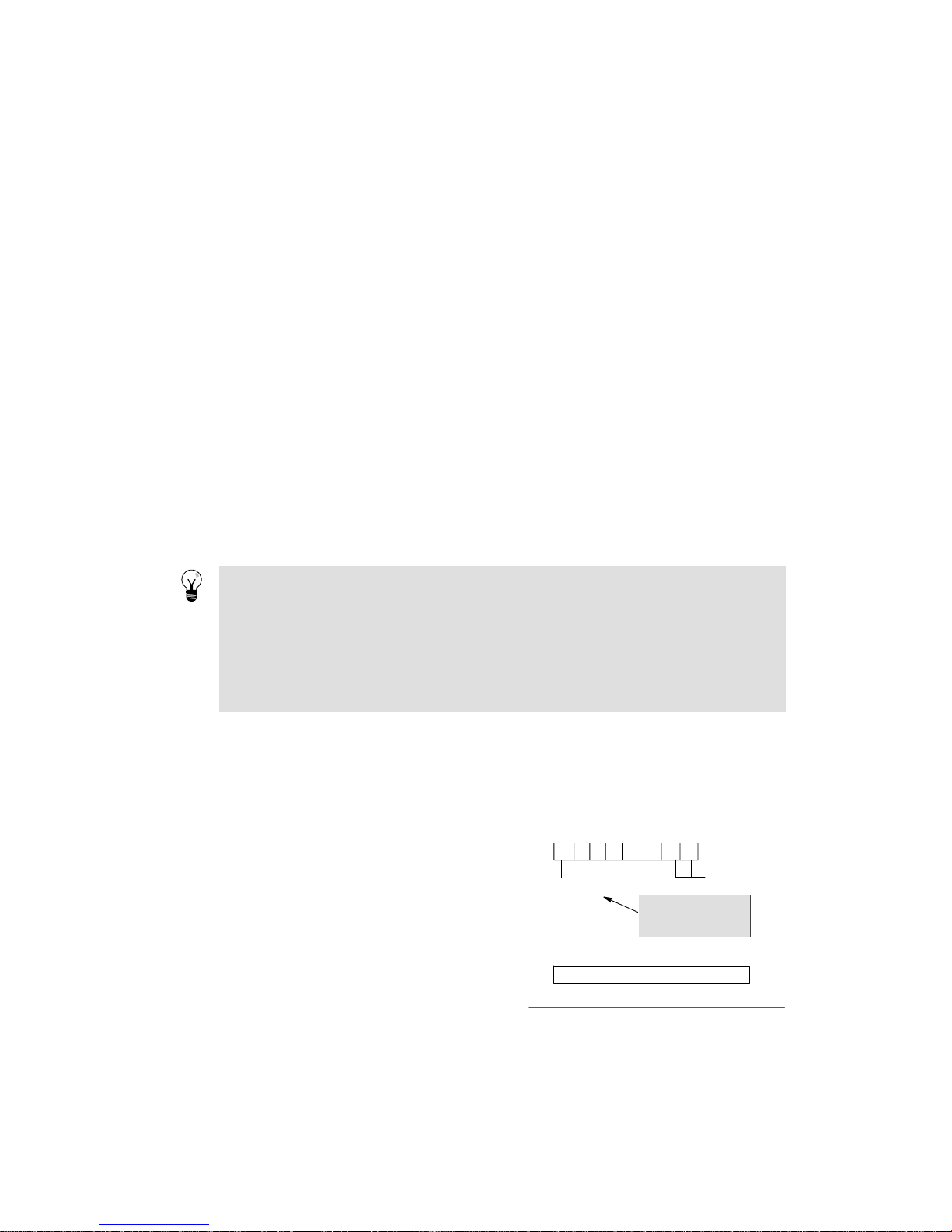
PLC Concepts Chapter 4
39
Saving the Retentive M Memory Area on Power Loss
If you configuredany of the first 14 bytes of bitmemory (MB0 to MB13) to be retentive,these
bytes are saved to permanent memory when the S7-200 loses power. By default, the first 14
bytes of M memory are selected to be non-retentive.
Restoring Data after Power On
When power is applied, theS7-200restores the program block and the system block from
permanent memory. The S7-200 then verifies thatthesupercapacitor and optionalbattery
cartridge,if installed, has successfully maintained the data stored in RAM memory. If the data was
successfully maintained, the retentive areas of user data memoryareleft unchanged. The
non-retentive portions of V memory are restored fromthe contents of the data block in permanent
memory. The non-retentive portionsofothermemory areas are cleared.
If the contents ofRAM werenotmaintained (such as afteranextendedpowerfailure), the S7-200
clears all userdataareas,sets the Retentive Data Lost memorybit(SM0.2), restores V memory
from the contentsofthedatablockinpermanent memory, and restores the first14 bytes of
M memory from permanentmemory if these bytes were previously configured as retentive.
Using Your Program to Save V Memory to Permanent Memory
You can save a value (byte, word, or double word) storedinany location of the V memory area to
permanent memory. A save to permanent memory operationtypically increases the scan time by
10 to 15 ms. The value written by the Save operation overwrites any previous value storedinthe
V memory area of permanent memory.
The save to permanent memory operationdoes not updatethedatainthememory cartridge.
Tip
Since the number of save operations to the permanentmemory (EEPROM)islimited (100,000
minimum,and1,000,000 typical),you should ensurethatonly necessary values are saved.
Otherwise,theEEPROMcan wear out and the CPU can fail.Typically,youshouldperform save
operations at theoccurrence of specific events thatoccurrather infrequently.
For example, ifthescan time of the S7-200 is 50 ms and a value was saved once per scan, the
EEPROM would last a minimum of 5,000 seconds, which is less than an hour and a half. On the
other hand, ifa value were saved once an hour,theEEPROMwouldlastaminimum of 11
years.
Copying V Memory to Permanent Memory
Special Memory Byte 31 (SMB31)commandstheS7-200to copy a value in V memory to the
V memory area of permanent memory. Special Memory Word 32 (SMW32) stores the address
location of the value thatistobe copied.Figure 4-17 shows the formatofSMB31and SMW32.
Use the following steps toprogram the S7-200 to
saveorwriteaspecificvalueinVmemory:
1. Load the V memory address of the value to
be saved in SMW32.
2. Load the size of the data in SM31.0 and
SM31.1, as shown in Figure 4-17.
3. Set SM31.7 to 1.
At the end of every scan cycle, the S7-200 checks
SM31.7; ifSM31.7equals1,thespecified value is
saved to permanent memory. The operation is
complete when the S7-200 resets SM31.7to0.
70
sv 0 0 0 0 0 s1 s0
SMB31
Save topermanent memory:
0=No
1=Yes
Size of value to be
saved:
00 -- byte
01 -- byte
10 -- word
11 -- double word
15
SMW32
0V memoryaddress
Specify the V memory addressas an offset from V0.
The CPU resets
SM31.7 aftereach
save operation.
Do not change the value in V memory until the
save operation is complete.
Figure 4-17 SMB31 and SMW32
Page 54
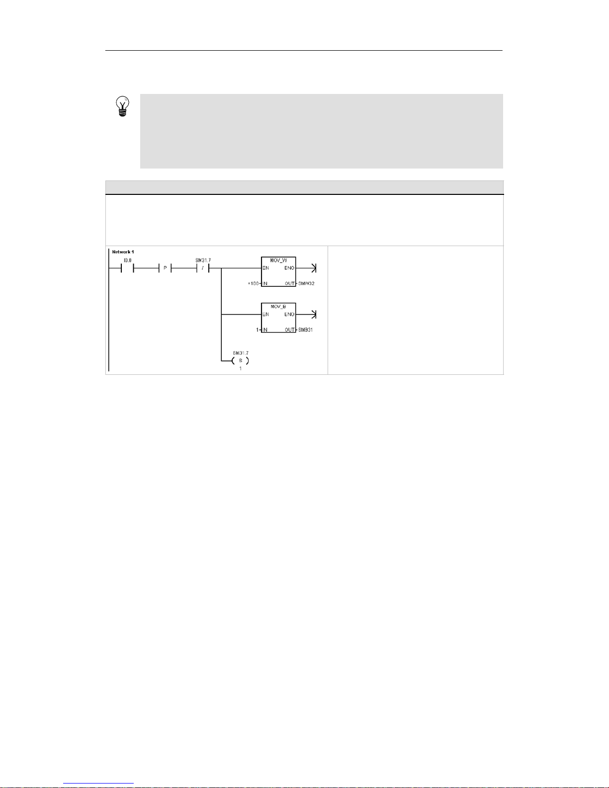
S7-200 Programmable Controller System Manual
40
Tip
Copying V Memory to permanent memory can be used to save values thatarecreated froman
HMI and stored from the programtotheinternal EEPROM.
To include the values saved to the internal EEPROM in your STEP 7-- Micro/WIN project,you
must upload the DB. However, this upload is only possible if the DB (whichincluded a variable
that was at an equal or higher address than the V Memory address saved in SMW32) was
previously downloaded fromSTEP7--Micro/WIN.
Sample Program: Copying V Memoryto the Permanent Memory
This example transfers VB100 to permanent memory. On a rising edge of I0.0, if another transfer is not in progress, it
loads the address of the V memory location to be transferred to SMW32. It selects the amount of V memory to transfer
(1=Byte; 2=Word; 3=Double Word or Real). It then sets SM31.7 to have the S7-200 transfer the data at the end of the
scan.
The S7-200 automatically resets SM31.7 when the transfer is complete.
Network 1 //Transfer a V memory
//location (VB100) to
//permanent memory
LD I0.0
EU
AN SM31.7
MOVW +100, SMW32
MOVB 1, SMB31
S SM31.7, 1
Selecting the Operating Mode for the S7-200 CPU
The S7-200 has two modes of operation: STOP mode and RUN mode. The status LEDs on the
front oftheCPU indicates the currentmodeofoperation. In STOPmode,the S7-200 is not
executing the program,andyou can download a program or theCPU configuration. In RUN
mode, the S7-200 is running theprogram.
- The S7-200 provides a mode switch for changing the mode of operation. You can use the
mode switch (locatedunderthefront access door of the S7-200) tomanually select the
operating mode:setting the mode switchtoSTOP mode stops the execution of the
program;setting the mode switch to RUN mode starts the executionofthe program; and
setting the mode switchtoTERM(terminal)modedoes not change the operating mode.
If a power cycle occurs when the mode switch is set to eitherSTOP or TERM, the S7-200
goes automaticallytoSTOP mode when power is restored.If a power cycle occurs when
the mode switch is set to RUN, the S7-200 goes to RUN mode when power is restored.
- STEP 7--Micro/WINallowsyou tochange the operating mode of the online S7-200. To
enable the softwaretochange the operating mode, you must manuallysetthemodeswitch
on the S7-200 to either TERM or RUN. You can use the PLC > STOP or PLC > RUN menu
commands or the associated buttonson the toolbarto change the operatingmode.
- You can insert the STOP instruction in your program to change the S7-200 to STOP mode.
This allows you to halt the executionofyourprogram based on the program logic.Formore
information about the STOP instruction, see Chapter 6.
Page 55

PLC Concepts Chapter 4
41
Using the S7-200 Explorer
The S7-200 Explorer is an extension to
the Windows Explorerapplication that
provides access to S7-200 PLCs and
allows the contents of each connected
PLC to be explored. The different blocks
that may reside in eitherthe PLC or the
memory cartridge can be determined.
Propertiesareavailable for each block.
Since the S7-200 Explorerisan
ext
ensiontothe
Win
d
owsExplore
r
extensiontotheWindowsExplorer
application,standard Windows
navigation and behaviorsaresupported.
Figure 4-18 S7-200 Explorer
The S7-200 Explorer is the mechanismused to readdatalogdatastored withinthe memory
cartridge.Refer to Chapter 14 for more information about data logs.
The S7-200 Explorer can also be used to read or write user files to the memorycartridge. These
can be any type of files, Worddocuments,bitmap files, jpeg files,orSTEP 7--Micro/WINprojects.
Features of the S7-200
The S7-200 provides several specialfeatures that allow you to customize how the S7-200
functions to betterfit your application.
The S7-200 Allows Your Program to Immediately Read or Write the I/O
The S7-200 instruction set provides instructions that immediately read from or write to the physical
I/O.These immediate I/O instructions allow direct access to the actual inputoroutputpoint, even
though the image registers are normally used as either the source or the destination for I/O
accesses.
The corresponding process-image input registerlocation is not modified when you use an
immediateinstruction to access an input point. The corresponding process-image outputregister
location is updated simultaneously when you use an immediate instruction to access an output
point.
Tip
The S7-200 handles reads of analog inputs as immediatedata,unless you enable analog input
filtering. When you write a value to an analog output, the output is updated immediately.
It is usually advantageoustouse the process-image register rather than to directlyaccess inputs
or outputs duringtheexecution of your program. Therearethree reasons forusingtheimage
registers:
- The sampling of all inputsatthestart of the scan synchronizes and freezes the values of
the inputs fortheprogram executionphase of the scan cycle.The outputsareupdatedfrom
the image register after the execution of the program is complete. This provides a stabilizing
effectonthesystem.
- Your program can access the image register much more quickly than itcan access I/O
points, allowing fasterexecution of the program.
- I/O pointsarebitentities and must be accessed as bits or bytes, but you can access the
image registerasbits, bytes, words, or double words. Thus, the image registers provide
additionalflexibility.
Page 56

S7-200 Programmable Controller System Manual
42
The S7-200 Allows Your Program to Interrupt the Scan Cycle
If you use interrupts, the routinesassociated with each interrupteventare storedas partofthe
program.The interrupt routines are not executed as part of the normal scan cycle, butare
executed when the interruptevent occurs (which could be at any point in the scan cycle).
Interrupts are servicedby the S7-200 on a first-come-first-servedbasiswithin their respective
priority assignments.SeetheInterrupt instructionsinChapter6formore information.
The S7-200 Allows You to Allocate Processing Time for Run Mode Edit
and Execution Status
You can configure a percentage of the scan cycle to be dedicated forprocessing a run mode edit
compilation or execution status.(Runmodeeditandexecution status are options providedby
STEP 7--Micro/WINtomakedebuggingyourprogram easier.) As you increase the percentage of
time thatisdedicated to these two tasks,you increasethescantime, which makes your control
process run more slowly.
The default percentageofthescan dedicatedtoprocessing run mode edits and execution status
is set to 10%. This settingwas chosen to providea reasonablecompromise for processingthe
compilation and status operations whileminimizing the impact to your control process.You can
adjust this value by 5% increments up to a maximum of 50%. To set the scan cycle time-slice for
background communications:
1. Select the View> Component>
System Block menu command
and select Background Time.
2. In the Background tab, use the
drop down box to select the
communicationsbackgroundtime.
3. Click OK to save your selection.
4. Download the modifiedsystem
block to the S7-200.
Figure 4-19 Communications Background Time
Page 57

PLC Concepts Chapter 4
43
The S7-200 Allows You to Set the States of Digital Ou tputs for Stop
Mode
The output table of the S7-200 allowsyou to determine whether to set the stateofthedigital
output points toknown values upon a transition to the STOP mode, or to leave the outputsinthe
state they were in beforethetransition to the STOP mode. The output table is partofthesystem
block that is downloaded and stored in the S7-200.
1. Select the View> Component>
System Block menu command
and select Output Table. Click on
the Digitaltab.
2. To freeze the outputs in their last
state,selectthe Freeze Outputs
checkbox.
3. To copy the tablevaluestothe
outputs, enterthe output table
values by clicking the checkbox for
each output bit you want to set to
On (1) aftera run-to-stop transition.
The default values of the tableare
all zeroes.
4. Click OK to save your selections.
5. Download the modifiedsystem
block to the S7-200.
Figure 4-20 Digital Output Table
The S7-200 Allows You to Configure the Value of Analog Outputs
The Analog Output Table allows you to set analog output points to known values after a
RUN-to-STOP transition, or to preservetheoutput values that existed beforethetransition to
STOP mode. The Analog Outputtable is part of the system block thatisdownloadedand storedin
the S7-200 CPU.
1. Select the View > Component >
System Block menu command
and select Output Table. Click on
the Analog tab.
2. To freeze the outputs in their last
state,selectthe Freeze Outputs
check box.
3. The Freeze Values table allows
you to set the analog outputs to a
known value (--32768 to 37262),
on a RUN-to-STOP transition.
4. Click OK to save your selections.
5. Download the modifiedsystem
block to the S7-200.
Figure 4-21 Analog Output Table
The S7-200 Allows You to Define Memory to Be Retained on Loss of
Power
You can define up to six retentive ranges to selecttheareasofmemory you want to retainthrough
power cycles. You can definerangesofaddressesinthefollowing memory areas to be retentive:
V, M, C, and T. For timers, only the retentive timers (TONR)can be retained.Thedefault setting for
the first14bytesofMMemoryistobenon-retentive.
Only the currentvaluesfortimers and counters can be retained: the timer and counter bitsare not
retentive.
Page 58

S7-200 Programmable Controller System Manual
44
Tip
Changing the range MB0 to MB13 to be retentive enables a special feature thatautomatically
saves these locations to the permanentmemory on power down.
To define the retentive memory:
1. Select the View> Component>
System Block menu command
and select RetentiveRanges.
2. Select the ranges of memory tobe
retained following loss of power
and click OK.
3. Download the modifiedsystem
block to the S7-200.
Figure 4-22 Retentive Memory
The S7-200 Allows You to Filter the Digital Inputs
The S7-200 allows you to select an input filter that defines a delay time (selectable from0.2msto
12.8 ms) for some or allofthelocaldigital input points. This delay helps to filter noise on the input
wiring thatcould cause inadvertent changes to the states of the inputs.
The input filteris part of the system block
that is downloaded and stored in the
S7-200. The defaultfilter time is 6.4 ms.
As shown in Figure 4-23, each delay
specification applies togroupsofinput
points.
To configure the delay times for the input
filter:
1. Select the View> Component>
System Block menu command
and select Input Filters. Click on
the Digitaltab.
2. Enter the amount of delay foreach
group of inputs and click OK.
3. Download the modifiedsystem
block to the S7-200.
Figure 4-23 Digital Input Filter
Tip
The digital inputfilteraffects the input value as seen by instruction reads, inputinterrupts, and
pulse catches. Depending on your filter selection, your program could miss an interrupt event or
pulse catch. The high speed counters count the events on the unfiltered inputs.
Page 59

PLC Concepts Chapter 4
45
The S7-200 Allows You to Filter the Analog Inputs
The S7-200 allows you to select softwarefiltering on individual analog inputs.Thefiltered value is
the average value of a preselected numberofsamplesofthe analog input. The filter specification
(number of samples and deadband) is the same for allanaloginputs forwhichfilteringisenabled.
The filterhasa fastresponsefeature to allow large changes to be quickly reflected in the filter
value. The filtermakes a step functionchangetothelatest analog input value when the input
exceeds a specified change from the currentvalue.This change, called the deadband, is
specified in counts ofthedigital value of the analog input.
The default configuration is to enable
filtering for all analog inputs except AIW0
and AIW2 on CPU 224XP.
1. Select the View> Component>
System Block menu command
and select Input Filters. Click on
the Analog tab.
2. Select the analog inputs thatyou
want to filter, the number of
samples, and the deadband.
3. Click OK.
4. Download the modifiedsystem
block to the S7-200.
Figure 4-24 Analog Input Filter
Tip
Do not use the analog filterwith modules thatpass digitalinformation or alarm indications in the
analog words. Always disable analog filtering for RTD, Thermocouple,andAS-Interface Master
modules.
Tip
AIW0 and AIW2 on the CPU 224XP are filteredby the analog to digital converter, and usually
will not need the additionalsoftware filter.
The S7-200 Allows You to Catch Pulses of Short Duration
The S7-200 provides a pulse catch featurewhichcan be used for some or all of thelocaldigital
input points.Thepulsecatchfeature allows you to capture high-going pulses or low-going pulses
that are of such a short durationthatthey would not always be seen when the S7-200 reads the
digitalinputs at the beginningofthescan cycle.Whenpulsecatchisenabledforan input,a
change in state of the input is latchedand held untilthe next input cycle update. This ensures that
a pulse which lasts for a short periodoftime is c aught and held untilthe S7-200 reads the inputs.
You can individually enable thepulse
catch operationforeachofthelocal
digitalinputs.
To access the pulse catch configuration
screen:
1. Select the View> Component>
System Block menu command
and select Pulse Catch Bits.
2. Click the correspondingcheck box
and click OK.
3. Download the modifiedsystem
block to the S7-200.
Figure 4-25 Pulse Catch
Page 60
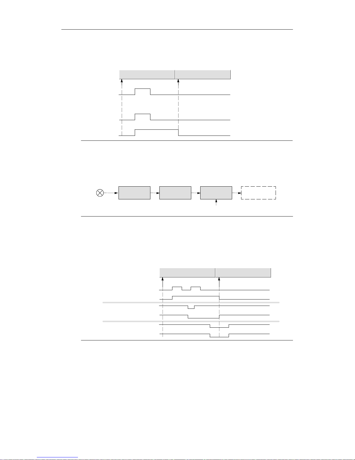
S7-200 Programmable Controller System Manual
46
Figure 4-26 shows the basic operation oftheS7-200with and without pulse catch enabled.
Physical Input
The S7-200 misses this pulse because the input
turned on and off before the S7-200 updated the
process-image input register
Input update
Disabled
Enabled
The S7-200 catches the pulse on the physical input
Scancycle Nextscan cycle
Input update
Output from
pulsecatch
Figure 4-26 Operation of the S7-200 with the Pulse Catch Feature Enabled and Disabled
Because the pulse catch function operateson the inputafter it passes through the input filter, you
must adjust the inputfilter time so that the pulse is not removed by the filter. Figure 4-27 shows a
block diagram of the digital input circuit.
Optical
Isolation
Pulse Catch Enable
External
Digital Input
Digital Input
Filter
Pulse
Catch
Input to S7-200
Figure 4-27 Digital Input Circuit
Figure 4-28 shows the response of an enabled pulse catch functiontovarious input conditions.If
you have more than one pulse in a given scan, only the first pulse is read.Ifyouhave multiple
pulses in a given scan, you should use the rising/falling edge interruptevents. (For a listing of
interrupt events, see Table 6-46.)
Input to pulse catch
Output from pulse catch
Scancycle Nextscan cycle
Input to pulse catch
Output from pulse catch
Input to pulse catch
Output from pulse catch
Input update Input update
Figure 4-28 Responses of the Pulse Catch Function to Various Input Conditions
Page 61
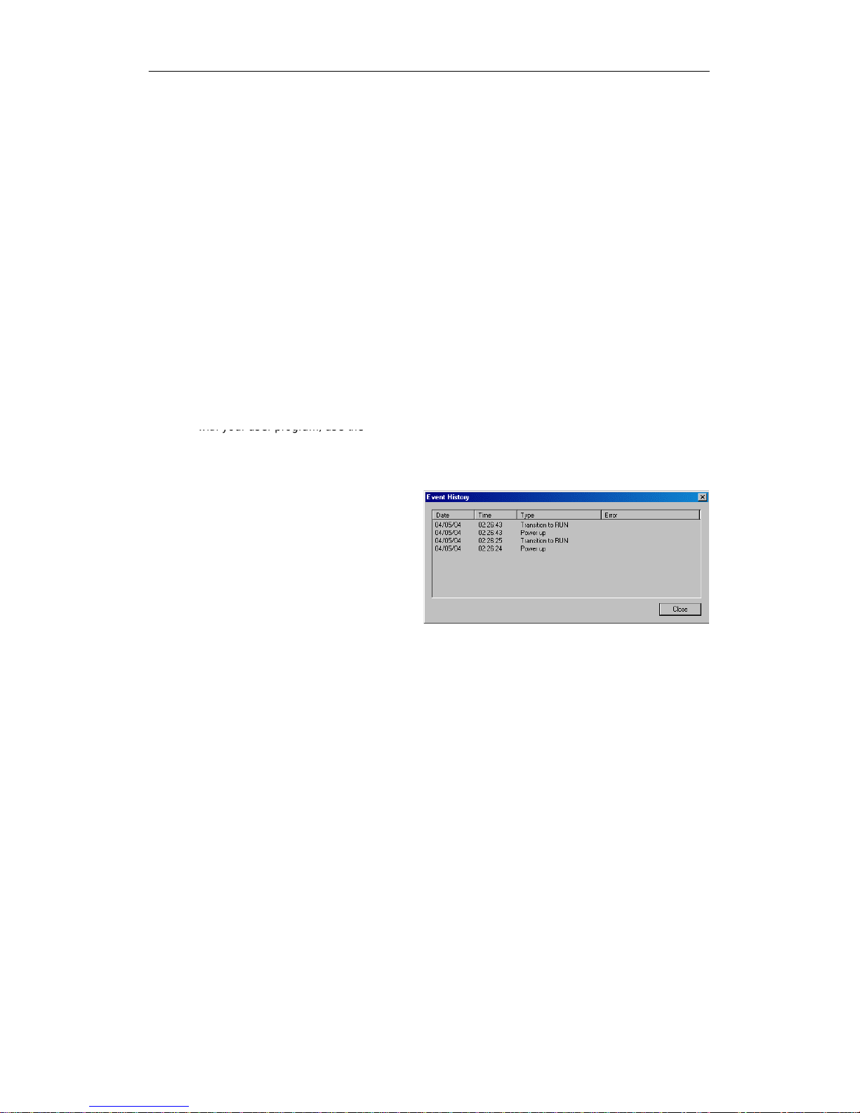
PLC Concepts Chapter 4
47
The S7-200 Provides a User-Controlled LED
The S7-200 provides an LED (SF/DIAG)thatcan indicatered (system faultLED)oryellow
(diagnosticLED).The diagnosticLED can be illuminated under user program control, or can
automatically illuminate under certain conditions:when an I/Opointordata value is forced,or
when a module has an I/O error.
To configure the automatic selectionsfor
the diagnostic LED:
1. Select the View> Component>
System Block menu command
and select ConfigureLED.
2. Click each item to eitherenable or
disable turningon the LED when
an I/O point or data value is forced,
or when a module has an I/O error.
3. Download the modifiedsystem
block to the S7-200.
To control the state of the diagnostic LED
with your user program,use the
withyouruserprogram,useth
e
Diagnostic LED instruction in Chapter 6.
Figure 4-29 Diagnostic LED
The S7-200 Maintains a History Log of Major CPU Events
The S7-200 maintains a log that contains
a time-stampedhistory of major CPU
events, such as when power is applied,
when the CPU enters RUN mode, and
when fatal errors occur.Your time-of-day
clock must be configured in orderto get
valid timeand date stamps on the log
entries.
To view the Event History log, select the
PL
C
>Inform
a
tio
n men
ucommand
and
PLC>Informationmenucommandand
select Event History.
Figure 4-30 Viewing the Event History Log
The S7-200 Allows You to Increase Your Available User Program
Memory
The S7-200 allows you to disable the run
mode edit featureintheCPU 224,
CPU 224XP, and CPU 226 in orderto
increase the amount of programmemory
available foryouruse.Refer to Table 1-1
to see the amount of program memory
for each CPU model.
To disable the run mode edit feature,
followthesesteps
1. Select the View> System Block
menu command and select
Increase ProgramMemory.
2. Click the Increase Memoryitem to
disable the run mode edit feature.
3. Download the modifiedsystem
block to the S7-200.
Figure 4-31 Disable Run Mode Edit
Page 62

S7-200 Programmable Controller System Manual
48
The S7-200 Provides Password Protection
All models of the S7-200 provide password protectionforrestricting access to specificfunctions.
A password authorizes access to the functionsand memory:without a password, the S7-200
provides unrestricted access. When it is passwordprotected, the S7-200 limits allrestricted
operations accordingto the configurationprovided when the password was installed
The password is not case-sensitive.
As shown in Table 4-3,theS7-200provides fourlevels of access restriction. Each level allows
certainfunctions to be accessible withouta password.Forthe four levels of access, entering the
correctpasswordprovides access to the functionsas noted below. The default condition for the
S7-200 is level 1 (no restric tion).
Entering thepasswordovera networkdoes not compromise the password protection for the
S7-200.
You can in effect,disable the password by changing the password level 4, 3,or2 to Level 1, since
Level 1 allows all unrestricted CPU access.
Table 4-3 Restricting Access tothe S7-200
CPU Function Level 1 Level 2 Level 3 Level 4
Read and write user data
Start, Stop, and Power--Up Reset
of the CPU
Access allowed Access allowed
Read and write the time--of--day
Clock
Access allowed
Upload the user program, data,
and the CPU configuration
Never allowed
Download of Program Block, Data
Block or System Block
Password
required (Never
allowed for
System Block)
Runtime Edits Never allowed
Delete of Program Block, Data
Block, or System Data Block
Access allowed
Password
required (Never
allowed for
System Block)
Copy of Program Block, Data
Block, or System Data Block to the
memory cartridge
Password
required
Passwor
d
required
Force data in status chart
Execute the single or multiple scan
Passwor
d
required
Writing of output in STOP mode
q
Resetof scan rates in PLC
information
Execution status
Project compare
N
ever a
l
l
owe
d
Having one user authorized to access restricted functions Reset of Scan Rates in PLC information
does not authorize otheruserstoaccess those functions. Only one user is allowedunrestricted
access to the S7-200 at a time.
Tip
After you enterthepassword,the authorization level forthatpassword remains effective forup
to one minute aftertheprogramming device has been disconnectedfrom the S7-200.Always
exit STEP 7-Micro/WINbefore disconnectingthe cable to prevent another user fromaccessing
the privilegesofthe programming device.
Page 63

PLC Concepts Chapter 4
49
Configuring a Password for the S7-200
The System Block dialog box (Figure 4-32)allows you to configurea password forthe S7-200.
The default conditionforthe S7-200 is set at Full (Level 1), no restriction.
1. Select the View> Component>
System Block menu command to
display the System Block dialog
box and select Password.
2. Select the appropriate levelof
access for the S7-200.
3. Enter and verify thepasswordfor
Partial(Level2) or Minimum
(Level 3).
4. Click OK.
5. Download the modifiedsystem
block to the S7-200.
Figure 4-32 Creating a Password
Recovering from a Lost Password
If you forgetthepassword,youmustclear the memory of the S7-200 and reload your program.
Clearing the memoryputstheS7-200inSTOP mode and resets the S7-200 to the factory-set
defaults,exceptforthe network address, baud rate, and the time-of-day clock.To clear your
program in the S7-200:
1. Select the PLC > Clear menu command to display the Cleardialogbox.
2. Select all threeblocks and confirm your action by clickingOK.
3. If a password had been configured, STEP7--Micro/WINdisplays a password-authorization
dialog box. To clear the password, enter CLEARPLC in the password-authorization dialog
box to continue the Clear Alloperation. (The CLEARPLC password is not case sensitive.)
The Clear All operation does not remove the program from a memory cartridge. Since the memory
cartridgestores the password along with the program,you must also reprogram the memory
cartridge to remove the lost password.
Warning
Clearing the S7-200memorycausestheoutputs to turn off(orin the case of an analog output,
to be frozen at a specific value).
If the S7-200 is connected to equipmentwhenyou clearthememory, changes in the state of the
outputs can be transmitted to the equipment.If you had configuredthe“safe state”for the
outputs to be different from the factory settings,changes in the outputscouldcause
unpredictableoperation of your equipment, which in turn could cause death or serious injury to
personnel, and/ordamagetoequipment.
Always followappropriate safety precautions and ensure that your processisina safe state
before clearingtheS7-200 memory.
Page 64
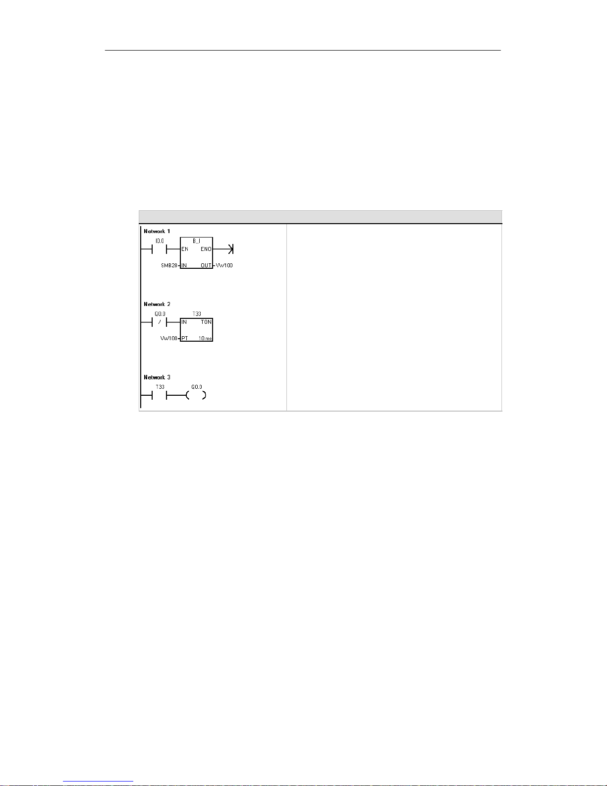
S7-200 Programmable Controller System Manual
50
The S7-200 Provides Analog Adjustment Potentiometers
The analog adjustment potentiometers are located under the front access cover of the module.
You can adjust these potentiometers to increaseordecreasevaluesthatare stored in bytes of
Special Memory (SMB). These read-only values can be used by the program for a variety of
functions,such as updatingthecurrent value for a timer or a counter,entering or changing the
preset values,orsetting limits. Use a small screwdriverto make the adjustments: turn the
potentiometer clockwise (to theright) to increasethevalue,andcounterclockwise (to the left) to
decrease the value.
SMB28 holds the digitalvaluethatrepresents the position of analog adjustment 0. SMB29 holds
the digitalvaluethat represents theposition of analog adjustment1.The analog adjustment has a
nominal range of 0 to 255 and a repeatability of ±2 counts.
Sample Program for Referencing the Value Entered with the Analog Adjustment Potentiometers
Network 1 //Read analog adjustment 0 (SMB28).
//Save the value as an integer in VW100.
LD I0.0
BTI SMB28, VW100
Network 2 //Use the integer value (VW100) as
//a preset for a timer.
LDN Q0.0
TON T33, VW100
Network 3 //Turn on Q0.0 when T33 reaches
//the preset value.
LD T33
=Q0.0
The S7-200 Provides High-speed I/O
High-Speed Counters
The S7-200 provides integrated high-speed counterfunctions that counthighspeed external
events withoutdegrading the performance of the S7-200.SeeAppendixA fortherates supported
by your CPU model. Each counter has dedicated inputs forclocks,direction control, reset,and
start,where these functions are supported.You can select differentquadrature modes for varying
the counting rate.Formore information on high-speed counters,see Chapter6.
High-Speed Pulse Output
The S7-200 supports high-speed pulse outputs,with outputs Q0.0 and Q0.1 generating eithera
high-speed pulse trainoutput (PTO)orpulse width modulation(PWM).
The PTO functionprovides a square wave (50% duty cycle) output for a specifiednumberof
pulses (from1 to 4,294,967,295 pulses) and a specified cycle time(in eithermicrosecond or
millisecond increments. You can program the PTO function to produce either one train of pulses or
a pulse profileconsisting of multiple trainsofpulses. For example, you can use a pulse profile to
control a steppermotorthrough a simple ramp up, run, and ramp down sequence or more
complicatedsequences.
The PWM function providesa fixedcycletime with a variable duty cycle output, withthecycletime
and the pulse width specified in either microsecond or millisecond increments. When the pulse
width is equal to the cycle time,the duty cycle is 100 percentand the outputisturned on
continuously. When the pulse width is zero, the duty cycle is 0 percent and the output is turnedoff.
For more information on the high-speedpulseoutputinstruction, see Chapter 6. For more
information about using PTO in open loop motion control, see Chapter 9.
Page 65

51
Programming Concepts, Conventions,
and Features
The S7-200 continuously executes your programto controlataskorprocess.You use
STEP 7--Micro/WIN tocreate this program and download it to the S7-200.STEP7-- Micro/WIN
provides a variety oftools and features for designing,implementing,anddebuggingyourprogram.
In This Chapter
Guidelines forDesigning a MicroPLC System 52.......................................
Basic Elements of a Program 53......................................................
Using STEP 7--Micro/WINtoCreate Your Programs 55..................................
Choosing Between the SIMATIC and IEC 1131--3 Instruction Sets 57......................
Understanding theConventions Used by the Program Editors 58..........................
Using Wizards To Help You Create Your Control Program 60..............................
Handling ErrorsintheS7-200 60.....................................................
Assigning Addresses and Initial Values in the Data Block Editor 62........................
Using the Symbol Table for Symbolic Addressing of Variables 62..........................
Using Local Variables 63............................................................
Using the Status Chart to Monitor Your Program 63......................................
Creating an Instruction Library 64.....................................................
Features forDebuggingYour Program 64..............................................
Page 66

S7-200 Programmable Controller System Manual
52
Guidelines for Designing a Micro PLC System
There are many methods for designinga MicroPLCsystem.Thefollowing general guidelines can
apply to many design projects.Ofcourse, you must follow the directives of your own company’s
procedures and the accepted practicesofyourown training and location.
Partition Your Process or Machine
Divide your process or machine intosections thathave a level of independence from each other.
These partitionsdetermine the boundaries between controllersand influence the functional
descriptionspecificationsand the assignmentofresources.
Create the Functional Specifications
Write the descriptions of operation for each section of the process or machine.Include the
followingtopics: I/O points, functionaldescription of the operation, states thatmustbeachieved
before allowingaction for each actuator(suchas solenoids,motors, and drives), descriptionofthe
operatorinterface, and any interfaces with other sections oftheprocessormachine.
Design the Safety Circuits
Identifyequipment requiringhard-wired logic for safety. Control devices can fail in an unsafe
manner, producing unexpected startup or change in the operation of machinery. Where
unexpected or incorrectoperation of the machinery could result in physicalinjury to people or
significantproperty damage, consideration should be given to the use of electro-mechanical
overrides which operateindependently of the S7-200 to prevent unsafe operations. The following
tasks should be included in the design of safetycircuits:
- Identifyimproper or unexpected operation of actuators thatcouldbe hazardous.
- Identifytheconditions that would assure the operation is not hazardous, and determinehow
to detect these conditions independently of the S7-200.
- IdentifyhowtheS7-200CPU and I/Oaffect the process when power is applied and
removed, and when errors aredetected. This information should only be used for designing
for the normaland expected abnormaloperation, and should not be relied on for safety
purposes.
- Design manual or electro-mechanical safety overrides that block the hazardous operation
independent of the S7-200.
- Provide appropriate status information fromtheindependentcircuits to the S7-200 so that
the program and any operatorinterfaces have necessary information.
- Identifyany othersafety-related requirements for safe operation of the process.
Specify the Operator Stations
Based on the requirements of the functional specifications, create drawingsofthe operator
stations.Include the following items:
- Overview showing the location of each operatorstation in relation to the process or
machine
- Mechanical layoutofthedevices,suchas display, switches, and lights,for the operator
station
- Electricaldrawings with the associated I/O of the S7-200 CPU or expansion module
Page 67
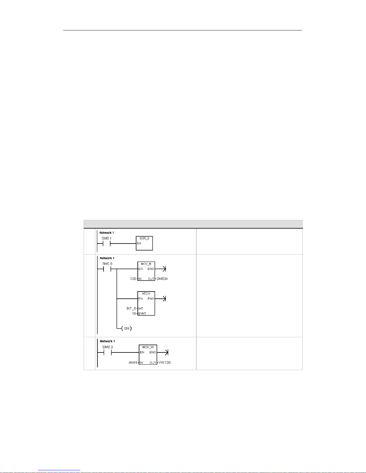
Programming Concepts, Conventions, and Features Chapter 5
53
Create the Configuration Drawings
Based on the requirements of the functional specification, createconfiguration drawings of the
control equipment. Include the following items:
- Overview showing the location of each S7-200 in relation to the process ormachine
- Mechanical layoutoftheS7-200andexpansionI/O modules (includingcabinets and other
equipment)
- Electricaldrawings for each S7-200 and expansion I/O module (including the device model
numbers, communications addresses, and I/O addresses)
Create a List of Symbolic Names (optional)
If you choose to use symbolic names for addressing,create a list of symbolicnames forthe
absolute addresses.Include not only the physical I/O signals,but also the other elements to be
used in your program.
Basic Elements of a Program
A program block is composed of executable code and comments. The executable code consists
of a main program and any subroutines or interrupt routines. The code is compiled and
downloaded to the S7-200; the programcomments are not. You can use the organizational
elements (mainprogram, subroutines, and interruptroutines) to structure your control program.
The following exampleshows a program thatincludes a subroutineand an interrupt routine. This
sample program uses a timed interrupt for reading the value of an analog input every 100 ms.
Example:Basic Elements of a Program
M
A
I
N
Network 1 //On first scan, call subroutine 0.
LD SM0.1
CALL SBR_0
S
B
R
0
Network 1 //Set the interval to 100 ms
//for the timed interrupt.
//Enable interrupt 0.
LD SM0.0
MOVB 100, SMB34
ATCH INT_0, 10
ENI
I
N
T
0
Network 1 //Sample the Analog Input 4.
LD SM0.0
MOVW AIW4,VW100
Main Program
The main body of the program contains the instructions that control your application.The S7-200
executes these instructions sequentially, once per scan cycle. The main program is also referred
to as OB1.
Page 68

S7-200 Programmable Controller System Manual
54
Subroutines
These optional elementsofyourprogram are executed only when called:bythemainprogram, by
an interruptroutine, or by anothersubroutine. Subroutinesare useful in cases where you want to
execute a function repeatedly.Rather than rewriting the logicforeachplaceinthemain program
where you want the function to occur, you can write the logic once in a subroutine and call the
subroutine as many times as needed during the main program. Subroutinesprovide several
benefits:
- Using subroutines reducestheoverall size of your program.
- Using subroutines decreasesyourscan timebecauseyou have moved the code out of the
main program.TheS7-200evaluates the code in the main program every scan cycle,
whether the code is executed or not, but theS7-200evaluates the code in the subroutine
only when you call the subroutine,and does not evaluate thecode duringthescans in
which the subroutine is notcalled.
- Using subroutines createscodethatis portable. You can isolate the code for a function in a
subroutine,andthencopy thatsubroutine into other programs with little or no rework.
Tip
Using V memory addresses can limittheportability of your subroutine,because itispossible for
V memory address assignment fromoneprogram to conflict with an assignment in another
program.Subroutines that use the local variable table (Lmemory) for alladdressassignments,
by contrast,arehighly portable because there is no concern about address conflicts between
the subroutine and anotherpartofthe programwhen usinglocalvariables.
Interrupt Routines
These optional elementsofyourprogram reacttospecific interrupt events. You design an interrupt
routine tohandlea pre-defined interrupt event. Whenever thespecified event occurs,theS7-200
executes the interrupt routine.
The interruptroutines are not calledby your main program. You associatean interrupt routine with
an interruptevent, and the S7-200 executes the instructions in the interrupt routine only on each
occurrence of the interrupt event.
Tip
Because it is not possible to predictwhentheS7-200 might generate an interrupt, it is desirable
to limitthe number of variables thatareusedbothby the interrupt routine and elsewhere in the
program.
Use the local variabletableofthe interruptroutine to ensure thatyourinterrupt routine uses only
the temporarymemory and does not overwrite data used somewhere else in your program.
There are a number of programmingtechniques you can use to ensure that data is correctly
shared between your main programand the interrupt routines. These techniques are described
in Chapter 6 with the Interrupt instructions.
Other Elements of the Program
Other blocks containinformation for the S7-200. You can choose to download these blocks when
you download your program.
System Block
The system block allows you to configure different hardware options for the S7-200.
Data Block
The data block stores the values for different variables (V memory)used by your program.You
can use the data block to enter initialvalues forthedata.
System
Block
Data
Block
Page 69
Programming Concepts, Conventions, and Features Chapter 5
55
Using STEP 7--Micro/WIN to Create Your Programs
To open STEP 7--Micro/WIN,double-click on the STEP 7-- Micro/WIN icon, or select the Start>
SIMATIC > STEP 7 MicroWIN V4.0 menu command. As shown in Figure 5-1, the
STEP 7--Micro/WINproject window provides a convenient workingspace forcreating your control
program.
The toolbars providebuttons for shortcuts tofrequently used menu commands. You can view or
hide any of the toolbars.
The navigation bar presentsgroupsof
icons for accessing different
programmingfeatures of
STEP 7--Micro/WIN.
The instruction tree displays allofthe
project objectsandtheinstructions for
creating yourcontrol program.You can
drag and drop individualinstructions
from the treeinto your program,or you
can double-click an instruction to insertit
at the currentlocation of the cursor in the
program editor.
The program editorcontains the program
logic and a local variabletable where
you can assign symbolic names for
temporarylocalvariables. Subroutines
and interruptroutines appear as tabs at
the bottom of the
prog
ram editorwindow.
Instruction tree
Program Editor
Navigation bar
thebottomoftheprogrameditorwindow
.
Click on the tabs to move between the
subroutines,interrupts, and the main
program.
Figure 5-1 STEP 7--Micro/WIN
STEP 7--Micro/WINprovidesthree editors for creating your program:LadderLogic (LAD),
StatementList(STL), and Function Block Diagram (FBD). Withsomerestrictions, programs
writteninany oftheseprogram editors can be viewed and edited with the other program editors.
Features of the STL Editor
The STL editor displays the programas a text-based language. The STL editor allows you to
create controlprograms by entering the instruction mnemonics. The STL editor also allows you to
create programsthatyoucouldnototherwise create with the LAD or FBD editors. This is because
you are programminginthenative language of the S7-200, ratherthan in a graphical editorwhere
some restrictions must be appliedinorderto draw the diagrams correctly. As shown in Figure 5-2,
this text-based concept is very similartoassembly language programming.
The S7-200 executes each instructionin
the order dictated by the program, from
top to bottom,and then restarts at the
top.
STL uses a logic stack to resolve the
control logic.You insert the STL
LD I0.0 //Read one input
A I0.1 //AND with another input
= Q1.0 //Write value to output 1
cotoogcousetteS
instructions for handlingthestack
operations.
Figure 5-2 Sample STL Program
Consider these main pointswhen you select theSTL editor:
- STL is most appropriateforexperienced programmers.
- STL sometimes allows you to solve problems thatyoucannotsolveveryeasily with the
LAD or FBD editor.
- You can only use the STL editor with the SIMATIC instruction set.
- While you can always use the STL editor to view or edit a programthatwascreated with the
LAD or FBD editors, the reverseisnotalwaystrue. You cannot always use the LAD or FBD
editors to displaya programthat was written with the STL editor.
Program
Editor
Page 70
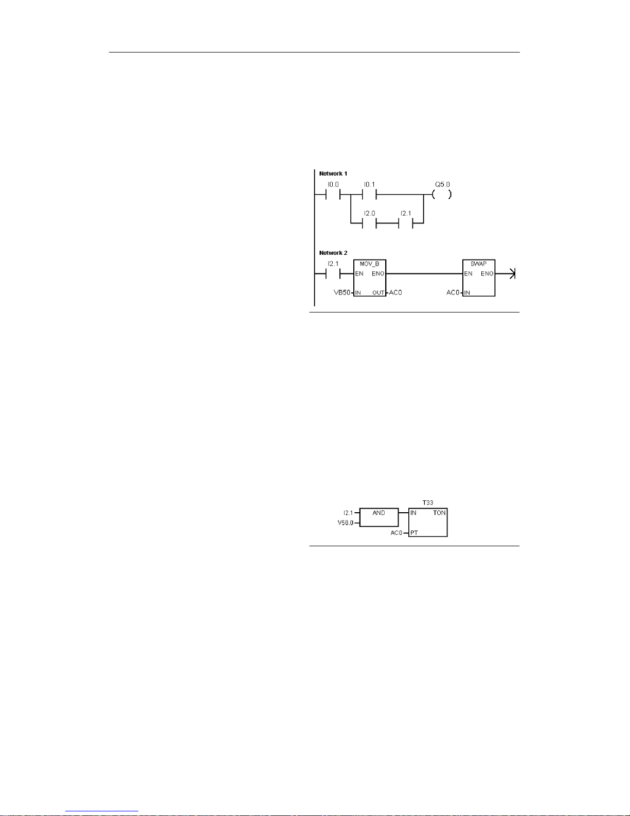
S7-200 Programmable Controller System Manual
56
Features of the LAD Editor
The LAD editor displays the programasa graphicalrepresentation similartoelectrical wiring
diagrams.Ladderprograms allowtheprogram to emulate the flow of electric currentfrom a power
source through a series of logicalinput conditions that in turn enable logicaloutputconditions. A
LAD program includes a leftpowerrail that is energized.Contacts that are closed allow energy to
flow throughthemtothe next element, and contacts thatareopenblockthatenergy flow.
The logic is separated intonetworks.
The program is executed one network at
a time, fromleft to right and then top to
bottom as dictatedby the program.
Figure 5-3 shows an example of a LAD
program.The variousinstructions are
representedby graphicsymbolsand
include threebasicforms.
Contacts representlogic input conditions
such as switches, buttons,orinternal
conditions.
Coils usually representlogic output
results such as lamps, motorstarters,
interposingrelays,orinternaloutpu
t
conditions.
Figure 5-3 Sample LAD Program
Boxes represent additional instructions, such as timers,counters, or math instructions.
Consider these main pointswhen you selecttheLAD editor:
- Ladder logic is easy for beginningprogrammers to use.
- Graphicalrepresentation is easy to understandand is populararoundtheworld.
- The LAD editor can be used with both the SIMATIC and IEC 1131--3 instructionsets.
- You can always use the STL editor to display a program created withtheSIMATIC LAD
editor.
Features of the FBD Editor
The FBD editor displays the programasa graphicalrepresentation that resembles common logic
gate diagrams.Therearenocontacts and coils as found in the LAD editor,butthere are
equivalent instructions that appear as box instructions.
Figure 5-4 shows an example of an FBD
program.
FBD does not use the concept of left and
right powerrails; therefore, the term
“power flow”is used to express the
analogous concept of controlflow
through the FBD logic blocks.
Figure 5-4 Sample FBD Program
The logic “1” path throughFBD elementsiscalled power flow. The origin of a power flow input and
the destinationofapowerflow outputcan be assigned directly to an operand.
The program logic is derivedfrom the connectionsbetweenthesebox instructions. That is, the
output fromone instruction (such as an AND box) can be used to enable another instruction (such
as a timer) to createthenecessary control logic.This connection concept allows you to solve a
wide variety of logicproblems.
Consider these main pointswhen you select theFBD editor:
- The graphical logic gate styleofrepresentationisgood forfollowing programflow.
- The FBD editor can be used with both the SIMATIC and IEC 1131--3 instructionsets.
- You can always use the STL editor to display a program created withtheSIMATIC FBD
editor.
Page 71

Programming Concepts, Conventions, and Features Chapter 5
57
Choosing Between the SIMATIC and IEC 1131--3 Instruction Sets
Most PLCs offersimilar basic instructions, but there are usually smalldifferences from vendor to
vendor in appearance, operation, and so forth. Over thelastseveral years, the International
Electrotechnical Commission (IEC) has developed an emerging global standardthatspecifically
relates to many aspects of PLC programming. This standard encourages differentPLC
manufacturers to offerinstructions that are the same in both appearance and operation.
Your S7-200 offers two instruction sets that allow you to solve a wide variety of automationtasks.
The IEC instruction set complies with the IEC1131-- 3 standardforPLCprogramming,and the
SIMATIC instruction set is designed specifically for the S7-200.
Tip
When STEP 7--Micro/WIN is set totheIECmode,it displays a red diamond 〈♦) in the Instruction
Tree beside the instructions that are not defined by the IEC 1131-- 3 standard.
There are a few key differences between the SIMATIC instruction set and the IEC instruction set:
- The IEC instruction set is restricted to those instructions that are standard among PLC
vendors. Some instructions that are normally included in the SIMATIC set are not standard
instructions in the IEC 1131-- 3 specification. These are still available foruse as
non-standardinstructions,butif you use them, the program is no longerstrictly IEC1131--3
compatible.
- Some IEC box instructions accept multipledataformats. This practice is often referred to as
overloading.Forexample, ratherthanhave separateADD_I(AddInteger) and ADD_R (Add
Real), mathboxes,theIECADDinstruction examines the format of the data being added
and automatically chooses the correct instruction in the S7-200. This can save valuable
program design time.
- When you use the IEC instructions,the instruction parametersare automatically checked
for the properdataformat, such as a signed integerversus an unsigned integer.For
example, an errorresults if you trytoenteraninteger value for an instruction thatexpected
a bit value (on/off). This feature helps to minimize programming syntax errors.
Consider these pointswhen you select eitherthe SIMATICortheIECinstruction set:
- SIMATIC instructions usuallyhave the shortestexecution times. Some IEC instructions
might have longer executiontimes.
- Some IEC instructions, such as timers,counters, multiply, and divide,operate differently
than theirSIMATIC counterparts.
- You can use all three program editors(LAD,STL,FBD) with the SIMATICinstructionset.
You can use only the LAD and FBD programeditors for IEC instructions.
- The operation of the IEC instructions is standard for different brands of PLCs, and the
knowledge about creatingan IEC-compliant program can be leveraged across PLC
platforms.
- While the IEC standarddefines fewerinstructions thanareavailable in the SIMATIC
instruction set,you can always include SIMATIC instructions in your IEC program.
- IEC 1131--3 specifies that variablesmustbedeclared witha type,and supportssystem
checking of data type.
Page 72
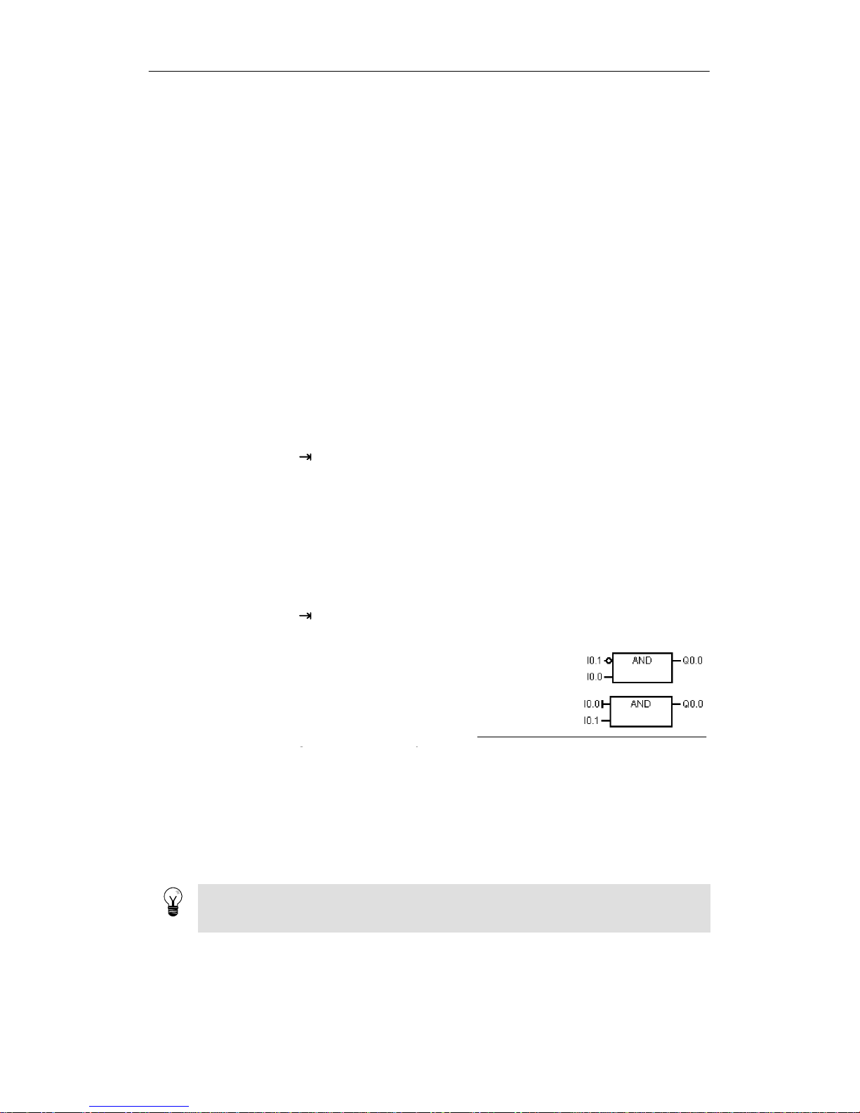
S7-200 Programmable Controller System Manual
58
Understanding the Conventions Used by the Program Editors
STEP 7--Micro/WINuses the following conventionsinallofthe program editors:
- A # in front of a symbol name (#var1)indicates that the symbol is oflocalscope.
- For IEC instructions, the % symbol indicates a direct address.
- The operand symbol “?.?” or“????”indicates that an operand configuration is required.
LAD programs are divided intosegments called networks. A networkisan orderedarrangement
of contacts,coils,and boxes that are allconnectedtoform a complete circuit: no short circuits, no
open circuits,and no reversepowerflow conditions exist.STEP7-- Micro/WIN allows you to create
comments for your LAD programona network-by-network basis.FBDprogramming uses the
network concept forsegmenting and commenting yourprogram.
STL programs do not use networks; however, you can use the NETWORK keyword to segment
your program.
Conventions Specific to the LAD Editor
In the LAD editor, you can use the F4, F6, and F9 keys on your keyboard to access contact, box,
and coil instructions. The LAD editorusesthefollowing conventions:
- The symbol “------>>” is an open circuit or a required power flowconnection.
- The symbol “ ” indicatesthatthe output is an optional power flowforan instruction that
can be cascaded or connected in series.
- The symbol “>>” indicatesthatyoucan use power flow.
Conventions Specific to the FBD Editor
In the FBD editor, you can use the F4, F6, and F9 keys on your keyboard to access AND, OR,
and box instructions.TheFBD editoruses the following conventions:
- The symbol “------>>” on an EN operand is a power floworoperandindicator. Itcan also
depict an open circuitora required power flowconnection.
- The symbol “ ” indicatesthatthe output is an optional power flowforan instruction that
can be cascaded or connected in series.
- The symbols “<<” and “>>” indicatethat you
can use either a value or power flow.
- Negation bubbles: The logicalNOTcondition
or invertedcondition of the operand or power
flow is shown by the small circleon theinput.
In Figure 5-5,Q0.0isequaltotheNOTofI0.0
AND I0.1. Negationbubblesareonlyvalidfor
Logical NOT
Condition
Immediate
Condition
g
y
Boolean signals, which can be specifiedas
parametersorpowerflow.
Figure 5-5 FBD Conventions
-
Immediateindicators: As shown in Figure 5-5, the FBD editor displays an immediate
condition of a Boolean operand witha vertical line on the input to an FBD instruction. The
immediateindicator causes an immediate read fromthespecified physical input. Immediate
operatorsareonlyvalid for physical inputs.
- Box with no input or output:A box withno inputindicates an instructionthatis independent
of power flow.
Tip
The number of operands can be expanded up to 32 inputs for AND and OR instructions. To add
or subtractoperandtics, use the “+”and “--” keys on your keyboard.
Page 73
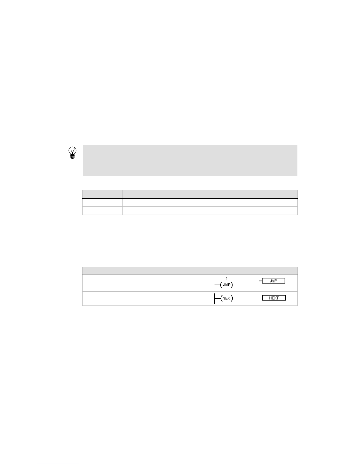
Programming Concepts, Conventions, and Features Chapter 5
59
General Conventions of Programming for an S7 -200
EN/ENO Definition
EN (Enable IN) is a Boolean input forboxes in LAD and FBD. Power flow must be present at this
input forthebox instruction to be executed. In STL, the instructions do not have an EN input,but
the top of stack value must be a logic “1” forthecorresponding STL instruction to be executed.
ENO (Enable Out) is a Boolean output forboxes in LAD and FBD. If the box has power flow at the
EN input and the box executes its function withouterror, then the ENO output passes power flow
to the next element.Ifan erroris detected in the execution of the box, then powerflow is
terminated at the box that generated the error.
In STL, there is no ENO output,buttheSTL instructions that correspond to the LAD and FBD
instructions with ENO outputsdo set a special ENO bit.Thisbitis accessiblewith the AND ENO
(AENO) instruction and can be used to generate the same effectas the ENO bit of a box.
Tip
The EN/ENO operands and data types are not shown in the valid operands table for each
instruction because the operands are the same for allLADand FBD instructions. Table5-1lists
these operands and data types for LAD and FBD. These operands apply to all LAD and FBD
instructions shown in this manual.
Table 5-1 EN/ENO Operands and Data Types for LAD and FBD
Program Editor Inputs/Outputs Operands DataTypes
LAD EN, ENO Power Flow BOOL
FBD EN, ENO I,Q,V,M,SM,S,T,C,L BOOL
Conditional/Unconditional Inputs
In LAD and FBD, a box or a coil that is dependent upon power flow is shown with a connection to
any element on the left side.A coilorbox thatis independent of power flow is shown with a
connection directly to the leftpowerrail. Table 5-2 shows an example of both a conditionalandan
unconditionalinput.
Table 5-2 Representation of Conditional and Unconditional Inputs
Power Flow LAD FBD
Instruction that is dependent on power flow (conditional)
Instruction that is independent of power flow (unconditional)
Instructions without Outputs
Boxes that cannot cascade are drawn with no Boolean outputs.These includetheSubroutine
Call, Jump,and Conditional Return instructions.Therearealsoladdercoils that can only be
placed on the left power rail. These include the Label, Next,Load SCR, Conditional SCR End, and
SCR End instructions.TheseareshowninFBD as boxes and are distinguished withunlabeled
power inputs and no outputs.
Compare Instructions
The compare instruction is executed regardless of the stateofpowerflow.If power flow is false,
the output is false.If power flow is true,the output is setdependingupon the resultofthe
compare. SIMATIC FBD, IEC Ladder,andIECFBD compareinstructions are shown as boxes,
although the operation is performed as a contact.
Page 74
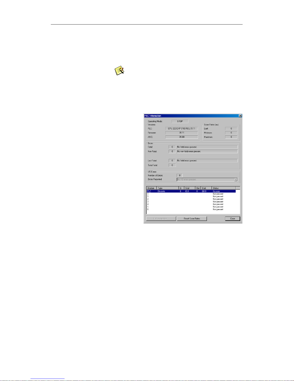
S7-200 Programmable Controller System Manual
60
Using Wizards To Help You Create Your Control Program
STEP 7--Micro/WINprovides wizards to make aspects of your programmingeasierand more
automatic.In Chapter 6, instructions that have an associatedwizard are identifiedbythefollowing
Instruction Wizard icon:
Instruction
Wizard
Handling Errors in the S7-200
The S7-200 classifieserrors as either fatalerrors or non-fatal errors.You can view the error codes
that were generatedby an errorby selecting the PLC > Information menu command.
Figure 5-6 shows the PLC Information
dialog box that displays theerror code
and the descriptionoftheerror.
The Last Fatal fieldshows the previous
fatal errorcode generatedby the
S7-200. This value is retainedover
power cycles if the RAM is retained.This
location is clearedeither whenever all
memory of the S7-200 is clearedorifthe
RAM is not retained afteraprolonged
power outage.
The Total Fatal field is the count of fatal
errors generated by the S7-200 since the
last timetheS7-200hadallmemory
areas cleared.Thisvalueisretained
over power cycles if the RAM is retained.
This location is clearedwheneverall
memory of the S7-200 is cleared,or
when the RAM is not retained aftera
prolonged power outage.
Appendix C lists the S7-200 errorcodes,
and Appendix D describes the special
memory
(SM)bit
s, w
h
ich
canbeuse
d
f
or
monitoring errors.
Figure 5-6 PLC Information Dialog Box
Non-Fatal Errors
Non-fatalerrors are those indicating problems withtheconstruction of the user program, with the
execution of an instruction in the user program,andwith expansion I/O modules.You can use
STEP 7--Micro/WINtoviewtheerror codes thatweregenerated by the non-fatalerror. There are
three basic categories of non-fatal errors.
Program-compile errors
The S7-200 compiles the programas itdownloads.If the S7-200 detects that the program violates
a compilation rule,the download is aborted and an errorcode is generated.(A program that was
already downloaded to the S7-200 would still exist in the permanentmemory and would not be
lost.)After you correctyour program, you can download it again. Refer to Appendix C for a listof
compile ruleviolations.
I/O errors
At startup,the S7-200 reads the I/O configuration from each module. During normal operation,the
S7-200 periodically checks the status of each module and compares it againsttheconfiguration
obtained duringstartup. If theS7-200detects a difference, the S7-200 sets the configuration error
bit in the module errorregister.The S7-200does not read inputdatafrom or write outputdatato
that module untilthe module configuration again matches the one obtained at startup.
Page 75
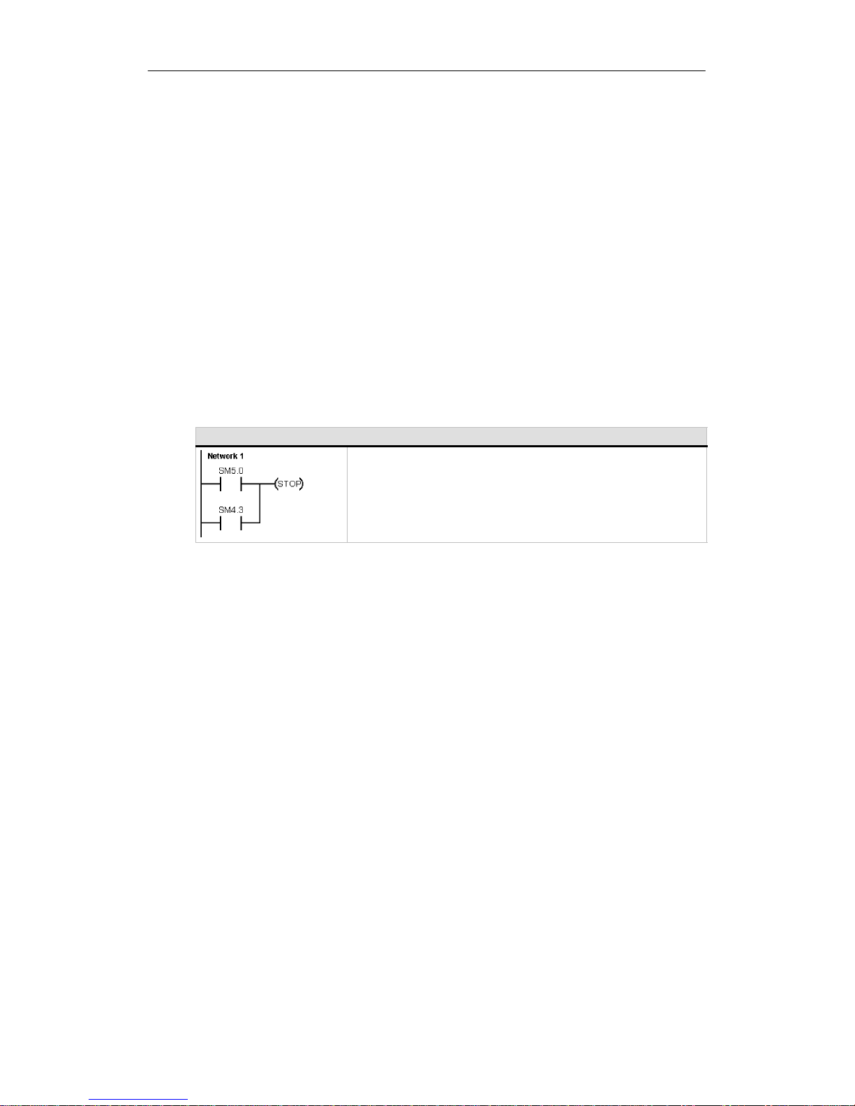
Programming Concepts, Conventions, and Features Chapter 5
61
The module status information is stored in special memory (SM) bits.Your program can monitor
and evaluate these bits.Referto Appendix D for moreinformationabouttheSMbits used for
reportingI/O errors. SM5.0 is the global I/O errorbit and remains set while an error condition
exists on an expansion module.
Program execution errors
Your program can create error conditions whilebeingexecuted.These errors can result from
improperuse of an instruction or fromtheprocessing of invaliddataby an instruction. For
example, an indirect-address pointer that was valid when the program compiledcouldbe modified
during the executionoftheprogram to pointtoanout-of-range address.This is an example of a
run-time programming problem. SM4.3 is set upon the occurrence of a run-time programming
problem and remains set whiletheS7-200isinRUNmode.(Refer to Appendix C forthelist of
run-time programming problems). Programexecution errorinformation is stored in special memory
(SM) bits.Your program can monitorand evaluatethese bits. RefertoAppendixD formore
information about the SM bits used for reporting program executionerrors.
The S7-200 does not change to STOP mode when it detects a non-fatal error.It only logs the
event in SM memory and continues with the executionofyourprogram. However, you can design
your program to forcetheS7-200toSTOP mode when a non-fatalerror is detected. The following
sample program shows a network of a program thatis monitoringtwooftheglobalnon-fatal error
bits and changes the S7-200 to STOP whenever eitherofthese bits turns on.
Sample Program: Logic for Detecting aNon-Fatal Error Condition
Network 1 //When an I/O error or a run-time error occurs,
//gotoSTOPmode
LD SM5.0
OSM4.3
STOP
Fatal Errors
Fatal errors cause the S7-200 to stop the execution of your program.Dependingupontheseverity
of the fatalerror,it can render the S7-200 incapable of performingany or allfunctions. The
objective forhandling fatalerrors is to bringtheS7-200toa safe statefrom which the S7-200 can
respond to interrogations about the existing error conditions.When a fatalerror is detected, the
S7-200 changes to STOP mode, turns on the SF/DIAG(Red)andtheSTOP LED, overrides the
output table,andturns off the outputs.The S7-200 remainsinthis conditionuntil the fatal error
condition is corrected.
Once you have made the changes to correct the fatal errorcondition, use one of the following
methods to restartthe S7-200:
- Turn the power off and then on.
- Change the mode switch from RUN or TERM to STOP.
- Select the PLC > Power-Up Reset menu command from STEP 7--Micro/WIN to restart the
S7-200. This forces theS7-200torestart and clear any fatal errors.
RestartingtheS7-200 clears the fatalerror condition and performs power-up diagnostictesting to
verify thatthe fatal errorhasbeen corrected. If another fatal errorcondition is found, the S7-200
again sets the fault LED,indicating that an error still exists.Otherwise, the S7-200 begins normal
operation.
Some error conditions can render the S7-200 incapableofcommunication. In these cases, you
cannot view the errorcode fromthe S7-200.These types of errors indicatehardware failuresthat
require theS7-200tobe repaired; they cannot be fixed by changes to the programorclearing the
memory of the S7-200.
Page 76
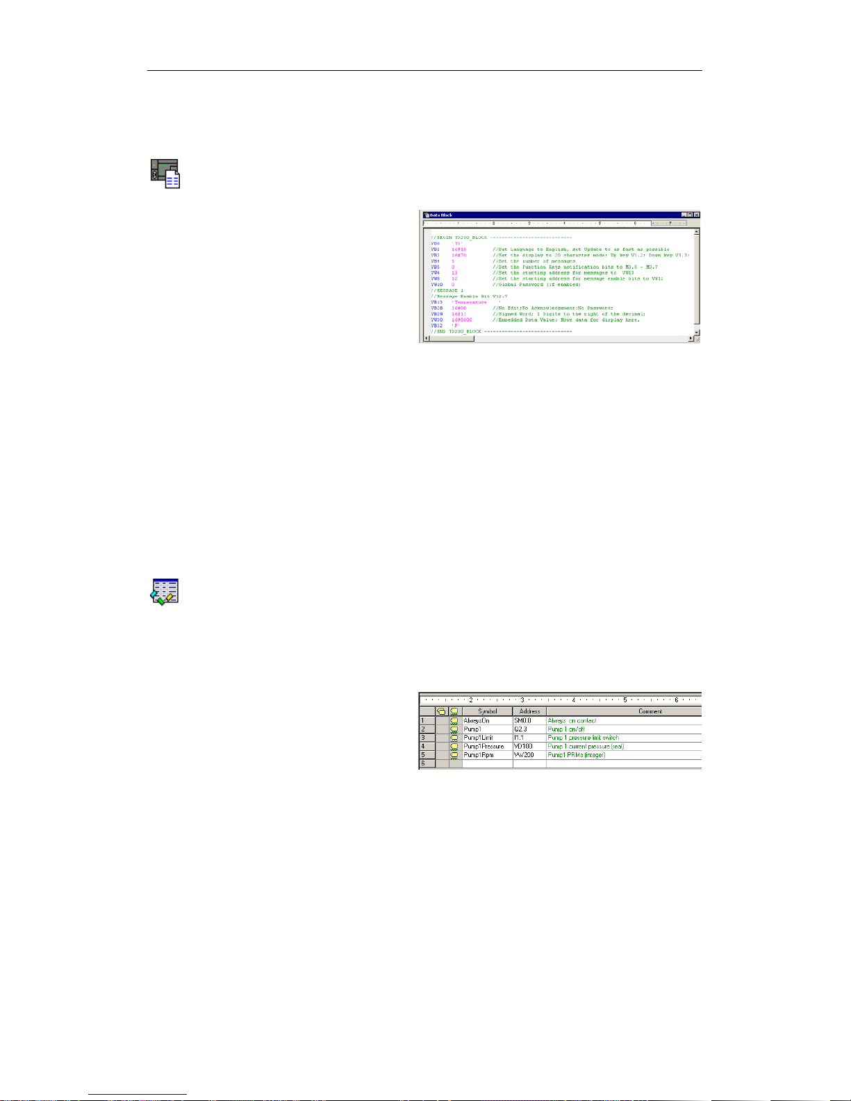
S7-200 Programmable Controller System Manual
62
Assigning Addresses and Initial Values in the Data Block Editor
The data block editor allowsyou to make initial data assignments to V memory (variable memory)
only. You can make assignments to bytes, words,ordoublewords of V memory. Comments are
optional.
The data block editor is a free-form text
editor;thatis, no specific fields are
defined forparticular types of
information. Afteryoufinish typing a line
and press the Enter key, the data block
editor formats the line (aligns columns of
addresses, data,comments; capitalizes
V memory addresses) and redisplaysit.
Pressing CTRL--ENTER, after
completingan assignmentline,
-
aut
o-incrementstheaddresstothenext
available address.
Figure 5-7 Data Block Editor
The data block editor assigns an appropriate amount of V memory based on your previous
address allocationsand thesize (byte, word, or double word)ofthe data value(s).
The firstline of the data block must have an explicit address assignment. Subsequent lines can
have explicit orimplicit address assignments. An implicitaddress assignmentismade by the
editor when you type multiple data values afterasingle address assignment,ortype a linethat
contains only data values.
The data block editor accepts uppercase or lowercaseletters and allows commas, tabs, or spaces
to serve as separators between addresses and data values.
Using the Symbol Table for Symbolic Addressing of Variables
The symbol table allows you to defineand editthesymbols that can be accessed by the symbolic
name anywhere in your program.You can create multiple symbol tables.There is also a tab in the
symbol table forsystem-defined symbolsthatyoucan use in your program.The symbol tableis
also referred to as the global variable table.
You can identify the operands of the instructions in your program absolutely or symbolically. An
absolute reference uses the memory area and bit or byte location toidentify the address. A
symbolic reference uses a combination of alphanumeric characters to identify the address.
For SIMATIC programs, you make global
symbol assignments by using the
symbol table.ForIECprograms, you
make global symbol assignmentsby
using the global variable table.
T
oassign a symbo
l
t
oana
d
d
ress:
Figure 5-8 Symbol Table
1. Click on the Symbol Table icon in the navigation bar to open the symbol table.
2. Enter the symbol name (forexample, Input1) in the Symbol Name column. The maximum
symbol length is 23 characters.
3. Enter the address (forexample, I0.0) in the Address column.
4. For an IEC global variabletable, enter a value in the Data Typecolumn or select one from
the list box.
You can create multiplesymboltables; however, you cannot use the same stringmorethan once
as a global symbol assignment, neitherwithin a single table nor among several tables.
Data
Block
Symbol
Table
Page 77
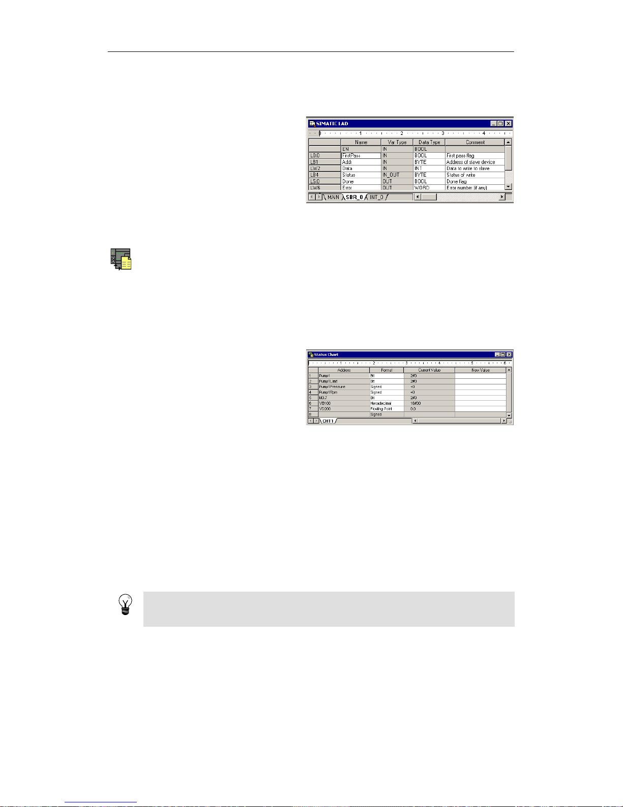
Programming Concepts, Conventions, and Features Chapter 5
63
Using Local Variables
You can use the local variable table of
the program editorto assign variables
that are unique to an individual
subroutine orinterrupt routine. See
Figure 5-9.
Local variables can be used as
parametersthatare passed in to a
subroutine and they increasethe
portability or reuse ofa subroutine.
Figure 5-9 Local Variable Table
Using the Status Chart to Monitor Your Program
A status chart allowsyou to monitoror modify the values of the process variables as your S7-200
runs the controlprogram. You can track the status of programinputs, outputs,orvariables by
displaying the currentvalues. The status chart also allows you to force or change the values of the
process variables.
You can create multiplestatus charts in orderto view elements fromdifferent portions of your
program.
To access the status chart, select the View> Component> Status Chart menu command or
click the Status Charticoninthe navigation bar.
When you create a status chart, you
enter addresses of process variables for
monitoring. You cannot view the status of
constants,accumulators, or local
variables.You can display a timer or
counter value eitherasa bitoras a
word. Displayingthevalue as a bit
shows the status of the timerorcounter
bit;displayingthevalueasawordshow
s
the timerorcountervalue.
Figure 5-10 Status Chart
To build a status chart and monitor the variables:
1. Enter the address foreach desiredvalueintheAddress field.
2. Select the data type in the Formatcolumn.
3. To view the status of the process variables in your S7-200, selecttheDebug > Chart
Status menu command.
4. To continuously sample the values, or to performa singlereadofthestatus, click the button
on the toolbar. The StatusChartals o allowsyou to modifyorforce values forthedifferent
process variables.
You can insert additionalrowsinyourStatus Chart by selecting the Edit > Insert>Row menu
command.
Tip
You can create multiplestatus charts todividethe variables into logicalgroups so thateach
group can be viewed in a shorter and separate status chart.
Status
Chart
Page 78
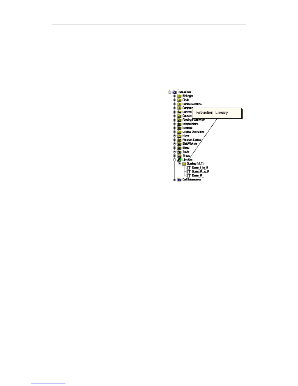
S7-200 Programmable Controller System Manual
64
Creating an Instruction Library
STEP 7--Micro/WINallows you either to create a custom library of instructions, or to use a library
created by someone else. See Figure 5-11.
To create a library of instructions, you create standardSTEP7-- Micro/WIN subroutineand
interruptroutines and group them together.You can hide the code in these routines to prevent
accidental changes or to protectthe technology (know-how)of the author.
To create an instruction library,perform the following
tasks:
1. Write the programas a standard
STEP 7--Micro/WINprojectand put the
function tobe includedinthelibrary into
subroutines orinterrupt routines.
2. Ensure that all V memorylocations in the
subroutines orinterrupt routines have been
assigned a symbolic name. To minimize the
amount of V memory that the library requires,
use sequential V memory locations.
3. Rename the subroutines or interrupt routines
to the names that you want to appear in the
instruction library.
4. Select the File > Create Library menu
command to compile the new instruction
library.
For more information about creating libraries,refer
to the online help for STEP 7--Micro/WIN.
Use the followingprocedure to access an instruction
in an instruction library:
Figure 5-11 Instruction Tree with Libraries
1. Add the Libraries directory to the instruction tree by selectingthe File > Add Libraries
menu command.
2. Select the specificinstruction and insert it into your program (as you would any standard
instruction).
If the library routine requires any V memory, STEP 7 -- Micro/WIN prompts you when the
project is compiled to assign a block of memory. Use the Library Memory Allocationdialog
box to assign blocks of memory.
Features for Debugging Y our Program
STEP 7--Micro/WINprovidesthefollowing features to help you debug your program:
- Bookmarks in your program tomake iteasy to move back and forth betweenlinesofalong
program.
- Cross Reference tableallow you to check the references used in your program.
- RUN-mode editing allowsyou to make small changes to your programwithminimal
disturbance totheprocesscontrolled by the program.You can also download the program
block when you are editing in RUN mode.
For more information about debugging your program, refer to Chapter8.
Page 79

65
S7-200 Instruction Set
This chapter describestheSIMATIC and IEC 1131instruction set for the S7-200 Micro PLCs.
In This Chapter
Conventions Used to Describe the Instructions 67.......................................
S7-200 Memory Ranges and Features 68..............................................
Bit Logic Instructions 70.............................................................
Contacts 70...................................................................
Coils 73.......................................................................
Logic Stack Instructions 75......................................................
Set and Reset Dominant BistableInstructions 77....................................
Clock Instructions 78................................................................
CommunicationsInstructions 81......................................................
Network Read and Network Write Instructions 81....................................
Transmitand Receive Instructions (Freeport) 86....................................
Get Port Address and Set PortAddressInstructions 95..............................
Compare Instructions 96............................................................
Comparing NumericalValues 96..................................................
Compare String 98.............................................................
Conversion Instructions 99...........................................................
Standard ConversionInstructions 99..............................................
ASCII ConversionInstructions 103.................................................
String ConversionInstructions 107.................................................
Encode and Decode Instructions 112...............................................
Counter Instructions 113..............................................................
SIMATIC Counter Instructions 113.................................................
IEC Counter Instructions 116......................................................
High-Speed CounterInstructions 118...................................................
Pulse Output Instruction 133..........................................................
Math Instructions 140................................................................
Add, Subtract,Multiply,andDivideInstructions 140...................................
MultiplyInteger to Double Integer and Divide Integer with Remainder 142................
Numeric FunctionsInstructions 143................................................
Incrementand DecrementInstructions 144..........................................
Proportional/Integral/Derivative (PID)Loop Instruction 145.................................
Interrupt Instructions 153.............................................................
Logical Operations Instructions 161....................................................
InvertInstructions 161............................................................
AND, OR, and Exclusive OR Instructions 162........................................
Move Instructions 164................................................................
Move Byte, Word,Double Word,or Real 164........................................
Move Byte Immediate(Readand Write) 165.........................................
Block Move Instructions 166......................................................
Page 80

S7-200 Programmable Controller System Manual
66
Program ControlInstructions 167......................................................
ConditionalEnd 167.............................................................
Stop 167.......................................................................
Watchdog Reset 167.............................................................
For--Next Loop Instructions 169....................................................
Jump Instructions 171............................................................
Sequence Control Relay (SCR)Instructions 172.....................................
Diagnostic LED Instruction 178....................................................
Shift and RotateInstructions 179.......................................................
Shift RightandShift Left Instructions 179............................................
Rotate Right and RotateLeftInstructions 179........................................
Shift RegisterBit Instruction 181...................................................
Swap Bytes Instruction 183.......................................................
String Instructions 184...............................................................
Table Instructions 189................................................................
AddToTable 189................................................................
First-In-First-Outand Last-In-First-Out 190..........................................
Memory Fill 192.................................................................
Table Find 193..................................................................
TimerInstructions 196................................................................
SIMATIC Timer Instructions 196...................................................
IEC TimerInstructions 201........................................................
Interval Timers 203..............................................................
Subroutine Instructions 204...........................................................
Page 81
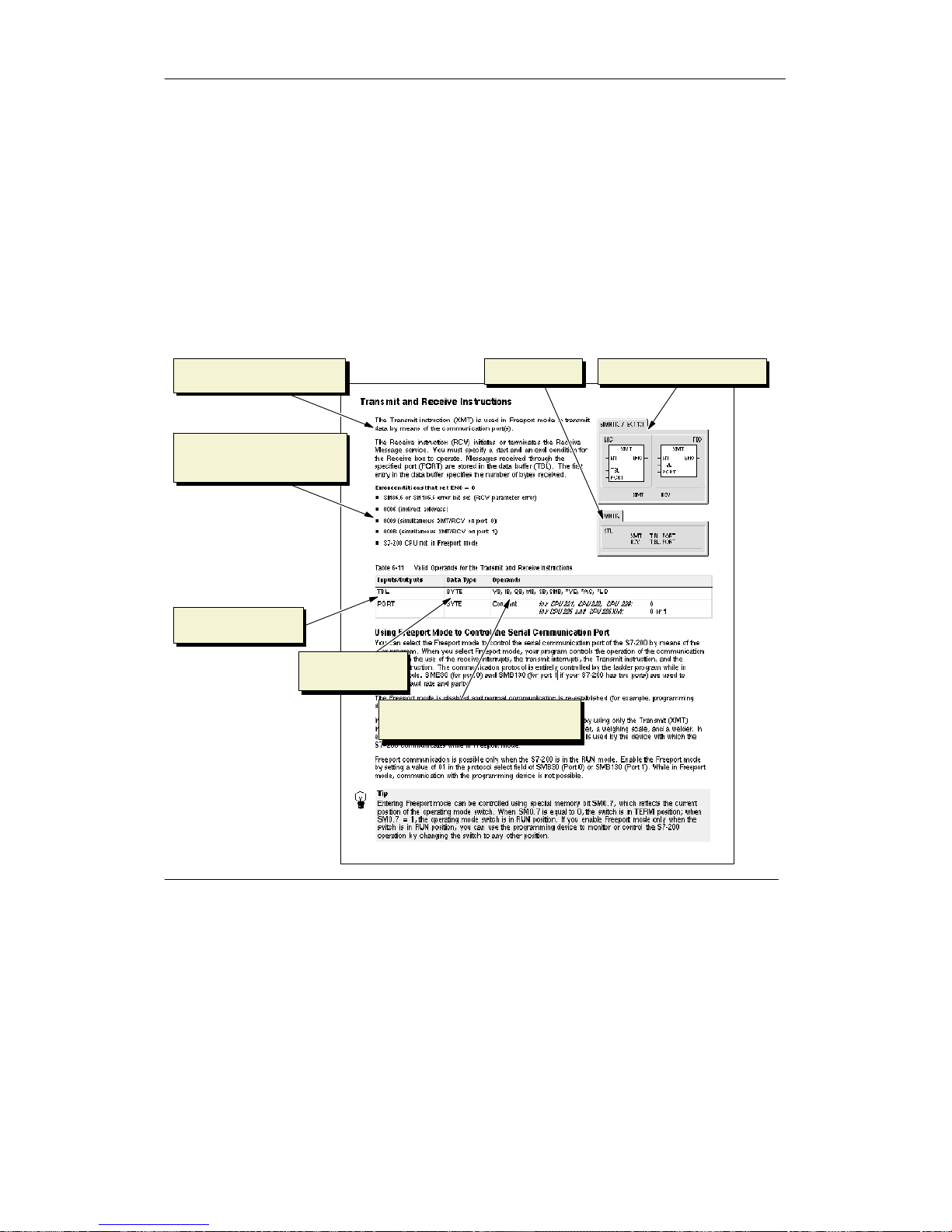
S7-200 Instruction Set Chapter 6
67
Conventions Used to Describe the Instructions
Figure 6-1 shows a typical description for an instruction and points to the different areas used to
describe the instruction and its operation. The illustration of the instruction shows the formatin
LAD, FBD, and STL. The operand table lists the operands fortheinstruction and shows the valid
data types, memory areasand sizes foreach operand.
EN/ENO operands and data types are not shown in the instruction operand tablebecause the
operands are the same for all LAD and FBD instructions.
- For LAD: EN and ENO are power flow and are BOOL data types.
- For FBD: EN and ENO are I, Q, V,M,SM, S, T,C,L,orpowerflow and are BOOL data
types.
LAD and FBD instructions
Valid data types
Operands for the
instruction
Valid memory areas and sizes for
the operands
Description of the instruction
and operands
STL instruction
List of the error conditions
that affect ENO and any SM
bits affected
Figure 6-1 Instruction Descriptions
Page 82

S7-200 Programmable Controller System Manual
68
S7-200 Memory Ranges and Features
Table 6-1 Memory Ranges and Features for the S7-200 CPUs
Description CPU 221 CPU 222 CPU 224
CPU 224XP
CPU 224XPsi
CPU 226
User program size
with run modeedit
without run modeedit
4096 bytes
4096 bytes
4096 bytes
4096 bytes
8192 bytes
12288 bytes
12288 bytes
16384 bytes
16384 bytes
24576 bytes
User data size 2048 bytes 2048 bytes 8192 bytes 10240 bytes 10240 bytes
Process-image input register I0.0 to I15.7 I0.0 to I15.7 I0.0 to I15.7 I0.0to I15.7 I0.0 to I15.7
Process-image output register Q0.0 to Q15.7 Q0.0 toQ15.7 Q0.0 to Q15.7 Q0.0 to Q15.7 Q0.0 toQ15.7
Analog inputs (read only) AIW0 to AIW30 AIW0 to AIW30 AIW0 to AIW62 AIW0 to AIW62 AIW0 to AIW62
Analog outputs (writeonly) AQW0 to AQW30 AQW0 to AQW30 AQW0 to AQW62 AQW0 to AQW62 AQW0 to AQW62
Variablememory (V) VB0 to VB2047 VB0 to VB2047 VB0 to VB8191 VB0 to VB10239 VB0 toVB10239
Local memory (L)
1
LB0toLB63 LB0toLB63 LB0toLB63 LB0toLB63 LB0toLB63
Bit memory (M) M0.0 to M31.7 M0.0 to M31.7 M0.0 to M31.7 M0.0 to M31.7 M0.0 toM31.7
Special Memory (SM)
Read only
SM0.0 to SM179.7
SM0.0 to SM29.7
SM0.0 to SM299.7
SM0.0 to SM29.7
SM0.0 to SM549.7
SM0.0 to SM29.7
SM0.0 to SM549.7
SM0.0 to SM29.7
SM0.0 to SM549.7
SM0.0 to SM29.7
Timers
Retentive on-delay 1 ms
10 ms
100 ms
On/Off delay 1 ms
10 ms
100 ms
256 (T0 toT255)
T0, T64
T1 to T4,and
T65toT68
T5 to T31,and
T69toT95
T32, T96
T33 to T36,and
T97toT100
T37 to T63,and
T101 to T255
256 (T0 toT255)
T0, T64
T1 toT4, and
T65toT68
T5 to T31,and
T69toT95
T32, T96
T33 to T36,and
T97toT100
T37 to T63,and
T101 to T255
256 (T0 toT255)
T0, T64
T1 toT4, and
T65toT68
T5 to T31,and
T69toT95
T32, T96
T33 to T36,and
T97toT100
T37 to T63,and
T101 to T255
256 (T0 toT255)
T0, T64
T1 toT4, and
T65toT68
T5 to T31,and
T69toT95
T32, T96
T33 to T36,and
T97toT100
T37 to T63,and
T101 to T255
256 (T0 toT255)
T0, T64
T1 toT4, and
T65toT68
T5 to T31,and
T69toT95
T32, T96
T33 to T36,and
T97toT100
T37 to T63,and
T101 to T255
Counters C0 to C255 C0 to C255 C0 to C255 C0 to C255 C0 to C255
High-speed counters HC0 toHC5 HC0 to HC5 HC0 to HC5 HC0 to HC5 HC0 to HC5
Sequential control relays (S) S0.0 to S31.7 S0.0 to S31.7 S0.0 to S31.7 S0.0 to S31.7 S0.0 to S31.7
Accumulator registers AC0toAC3 AC0toAC3 AC0toAC3 AC0toAC3 AC0toAC3
Jumps/Labels 0to255 0to255 0to255 0to255 0to255
Call/Subroutine 0to63 0to63 0to63 0to63 0to127
Interrupt routines 0to127 0to127 0to127 0to127 0to127
Positive/negative transitions 256 256 256 256 256
PID loops 0to7 0to7 0to7 0to7 0to7
Ports Port 0 Port 0 Port 0 Port 0, Port 1 Port 0, Port 1
1
LB60 toLB63 are reserved by STEP7--Micro/WIN, version 3.0 or later.
Page 83

S7-200 Instruction Set Chapter 6
69
Table 6-2 Operand Ranges for the S7-200 CPUs
Access Method CPU 221 CPU 222 CPU 224
CPU 224XP
CPU 224XPsi
CPU 226
Bitaccess (byte.bit) I
Q
V
M
SM
S
T
C
L
0.0 to 15.7
0.0 to 15.7
0.0 to 2047.7
0.0 to 31.7
0.0 to 165.7
0.0 to 31.7
0to255
0to255
0.0 to 63.7
0.0 to 15.7
0.0 to 15.7
0.0 to 2047.7
0.0 to 31.7
0.0 to 299.7
0.0 to 31.7
0to255
0to255
0.0 to 63.7
0.0 to 15.7
0.0 to 15.7
0.0 to 8191.7
0.0 to 31.7
0.0 to 549.7
0.0 to 31.7
0to255
0to255
0.0 to 63.7
0.0 to 15.7
0.0 to 15.7
0.0 to 10239.7
0.0 to 31.7
0.0 to 549.7
0.0 to 31.7
0to255
0to255
0.0 to 63.7
0.0 to 15.7
0.0 to 15.7
0.0 to 10239.7
0.0 to 31.7
0.0 to 549.7
0.0 to 31.7
0to255
0to255
0.0 to 63.7
Byteaccess IB
QB
VB
MB
SMB
SB
LB
AC
KB (Constant)
0to15
0to15
0 to 2047
0to31
0to165
0to31
0to63
0to3
KB (Constant)
0to15
0to15
0 to 2047
0to31
0to299
0to31
0to63
0to3
KB (Constant)
0to15
0to15
0 to 8191
0to31
0to549
0to31
0to63
0to3
KB (Constant)
0to15
0to15
0 to 10239
0to31
0to549
0to31
0to63
0to255
KB (Constant)
0to15
0to15
0 to 10239
0to31
0to549
0to31
0to63
0to255
KB (Constant)
Wordaccess IW
QW
VW
MW
SMW
SW
T
C
LW
AC
AIW
AQW
KW (Constant)
0to14
0to14
0 to 2046
0to30
0to164
0to30
0to255
0to255
0to62
0to3
0to30
0to30
KW (Constant)
0to14
0to14
0 to 2046
0to30
0to298
0to30
0to255
0to255
0to62
0to3
0to30
0to30
KW (Constant)
0to14
0to14
0 to 8190
0to30
0to548
0to30
0to255
0to255
0to62
0to3
0to62
0to62
KW (Constant)
0to14
0to14
0 to 10238
0to30
0to548
0to30
0to255
0to255
0to62
0to3
0to62
0to62
KW (Constant)
0to14
0to14
0 to 10238
0to30
0to548
0to30
0to255
0to255
0to62
0to3
0to62
0to62
KW (Constant)
Double word access ID
QD
VD
MD
SMD
SD
LD
AC
HC
KD (Constant)
0to12
0to12
0 to 2044
0to28
0to162
0to28
0to60
0to3
0to5
KD (Constant)
0to12
0to12
0 to 2044
0to28
0to296
0to28
0to60
0to3
0to5
KD (Constant)
0to12
0to12
0 to 8188
0to28
0to546
0to28
0to60
0to3
0to5
KD (Constant)
0to12
0to12
0 to 10236
0to28
0to546
0to28
0to60
0to3
0to5
KD (Constant)
0to12
0to12
0 to 10236
0to28
0to546
0to28
0to60
0to3
0to5
KD (Constant)
Page 84
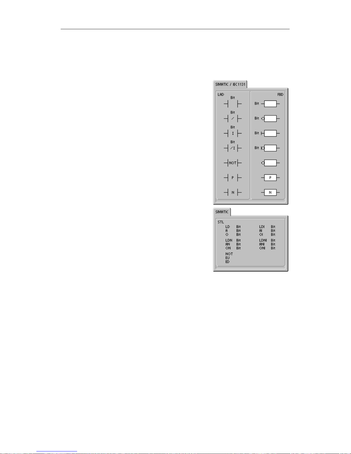
S7-200 Programmable Controller System Manual
70
Bit Logic Instructions
Contacts
Standard Contacts
The Normally Open contact instructions (LD, A, and O) and
Normally Closed contactinstructions (LDN, AN, ON) obtain
the referencedvaluefrom the memoryorfrom the
process-imageregister. The standard contactinstructions
obtain the referenced value from the memory (or
process-imageregister if the data type is I or Q).
The Normally Open contactisclosed(on)whenthebitis
equal to 1, and the NormallyClosedcontactis closed (on)
when the bit is equal to 0. In FBD, inputs to both the And
and Or boxes can be expanded to a maximumof32 inputs.
In STL, the NormallyOpen instructions Load, AND, or OR
the bit value of the address bitto the top of the stack, and
the NormallyClosedinstructions Load, AND, or OR the
logical NOT of thebitvalue to the top of the stack.
Immediate Contacts
An immediate contactdoes not relyontheS7-200scan
cycle to update; itupdatesimmediately. The Normally Open
Immediatecontactinstructions (LDI, AI,and OI)and
Normally Closed Immediate c ontact instructions (LDNI,ANI,
and ONI) obtain the physicalinputvalue when the
instruction is executed, but the process-image registeris
not updated.
The Normally Open Immediate contact is closed (on)when
the physical inputpoint(bit) is 1,and the Normally Closed
Immediatecontactis closed (on)when the physicalinput
point (bit)is 0. The Normally Open instructions immediately
Load, AND, or OR the physical inputvaluetothetopofthe
stack, and the NormallyClosedinstructions immediately
Load, AND, or OR the logical NOT of the value of the
physical input pointto the top of the stack.
NOT Instruction
The Not instruction (NOT) changes the state of power flow
input (thatis, it changes the value on the top of the stack
from0to1orfrom1to0).
Page 85
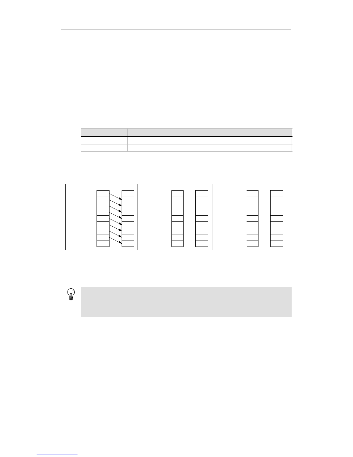
S7-200 Instruction Set Chapter 6
71
Positive and Negative Transition Instructions
The Positive Transition contact instruction (EU)allows power to flow forone scan for each
off-to-on transition. The Negative Transition contact instruction(ED)allows power to flow for one
scan for each on-to-off transition. ForthePositive Transition instruction, detection of a 0-to-1
transition in the value on the top of the stack sets the top of the stackvalueto1;otherwise, it is set
to 0. For a Negative Transition instruction, detection of a 1-to-0transition in the value on the top of
the stack sets the top of the stack value to 1; otherwise, it is set to 0.
For run mode editing (whenyou edityourprogram in RUN mode),you must enteraparameter for
the PositiveTransition and Negative Transitioninstructions. Refer to Chapter 5 formore
information about editinginRUNmode.
Table 6-3 Valid Operands for the Bit Logic Input Instructions
Inputs/Outputs Data Type Operands
Bit BOOL I,Q,V,M,SM,S,T,C,L,PowerFlow
Bit (immediate) BOOL I
As shown in Figure 6-2, the S7-200 uses a logic stack to resolve the controllogic. In these
examples, “iv0”to “iv7”identify theinitial values of the logic stack, “nv” identifies a new value
provided by the instruction, and “S0” identifies the calculated value that is stored in the logicstack.
Or (O,OI, ON,
ONI)
ORs a new
value (nv) with
the initialvalue
(iv) at the top of
the stack.
S0=iv0 OR nv
Before After
S0
1
iv0
iv1
iv2
iv3
iv4
iv5
iv6
iv7
iv8
iv1
iv2
iv3
iv4
iv5
iv6
iv7
iv8
Load (LD,LDI,
LDN, LDNI)
Loads a new
value (nv) onto
the stack.
iv6
iv7
nv
iv0
iv1
iv2
iv3
iv4
iv5
iv0
iv1
iv2
iv3
iv4
iv5
iv6
iv7
iv8
2
Before A fter
And (A, AI, AN,
ANI)
ANDs a new
value (nv) with
the initialvalue
(iv) at the top of
the stack.
S0=iv0 AND nv
Before After
S0
1
iv0
iv1
iv2
iv3
iv4
iv5
iv6
iv7
iv8
iv1
iv2
iv3
iv4
iv5
iv6
iv7
iv8
1
S0 identifies the calculated value that is stored in the logic stack.
2
After the execution of a Load, the value iv8 is lost.
Figure 6-2 Operations of the Contact Instructions.
Tip
Because the Positive Transition and Negative Transition instructions require an on-to-offor an
off-to-on transition, you cannot detectan edge-up or edge-down transition on the first scan.
During the first scan, the S7-200 sets the state of the bit specified by these instructions. On
subsequent scans, these instructions can then detecttransitions for the specified bit.
Page 86
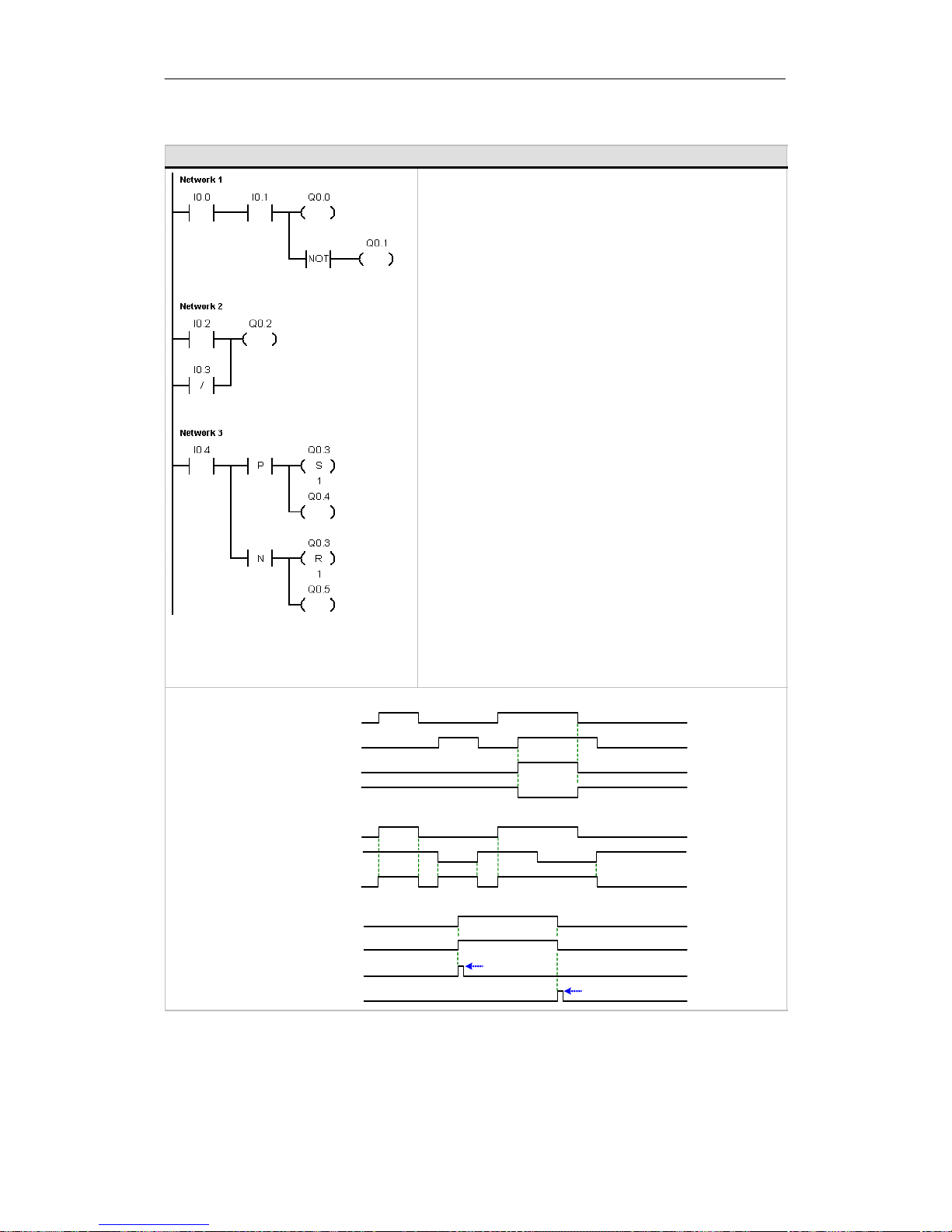
S7-200 Programmable Controller System Manual
72
Example: Contact Instructions
Network 1 //N.O. contacts I0.0 AND I0.1 must be on
//(closed) to activate Q0.0. The NOT
//instruction acts as an inverter. In RUN
// mode, Q0.0 and Q0.1 have opposite logic states.
LD I0.0
AI0.1
=Q0.0
NOT
=Q0.1
Network 2 //N.O. contact I0.2 must be on or N.C.
//contact I0.3 must be off to activate Q0.2.
// One or more parallel LAD branches
//(OR logic inputs) must be true to make
//the output active.
LD I0.2
ON I0.3
=Q0.2
Network 3 //A positive Edge Up input on a P contact
//or a negative Edge Down input on a N contact
//outputs a pulse with a 1 scan cycle
//duration. In RUN mode, the pulsed state
//changes of Q0.4 and Q0.5 are too fast to
// be visible in program status view.
//The Set and Reset outputs latch the
// pulse in Q0.3 and makethestate
//change visible in program status view.
LD I0.4
LPS
EU
S Q0.3, 1
=Q0.4
LPP
ED
R Q0.3, 1
=Q0.5
I0.0
I0.1
Q0.0
Q0.1
I0.2
I0.3
Q0.2
I0.4
Q0.3
Q0.4
Q0.5
Timing Diagram
Network 2
Network 3
Network 1
On for one scan
On for one scan
Page 87
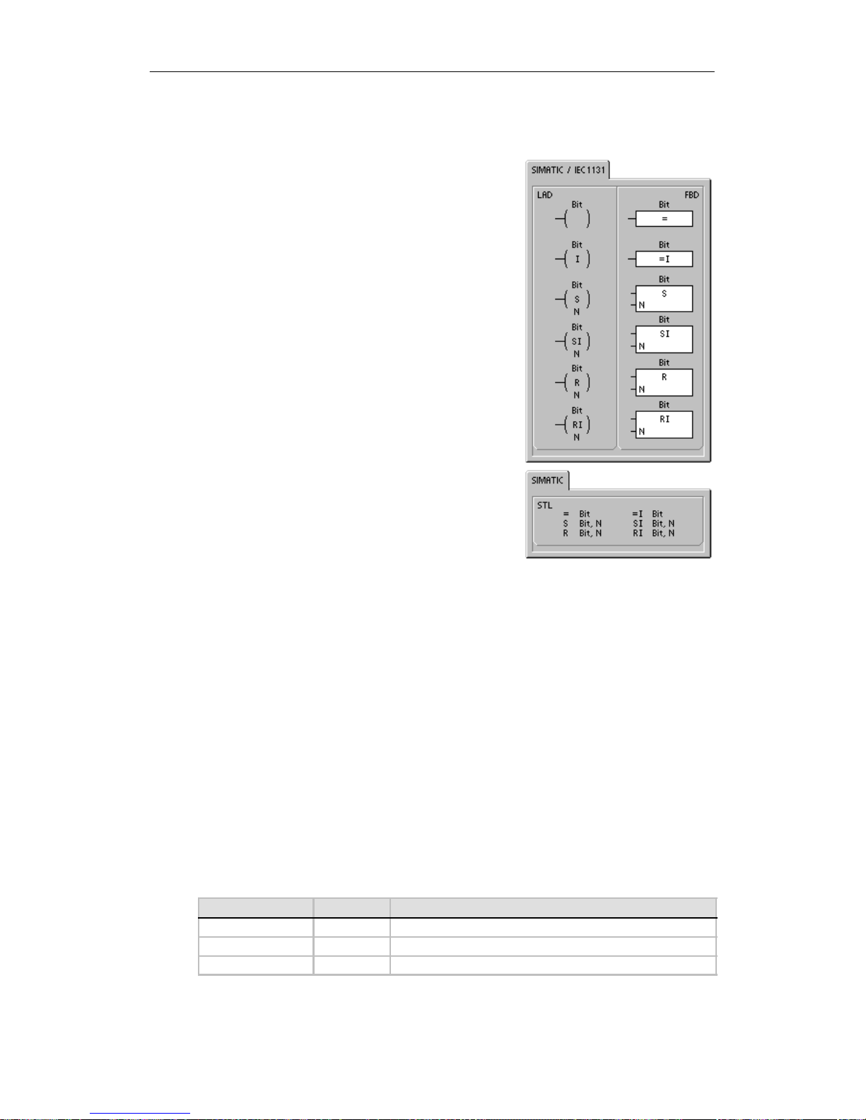
S7-200 Instruction Set Chapter 6
73
Coils
Output
The Output instruction (=) writes the new value for the
output bittotheprocess-image register.Whenthe Output
instruction is executed, the S7-200 turns the output bit in the
process-imageregister on or off.For LAD and FBD, the
specified bitissetequaltopowerflow.For STL, the value
on the top of the stack is copied to the specifiedbit.
Output Immediate
The Output Immediate instruction(=I) writes the new value
to both the physical outputand the corresponding
process-imageregister location when the instructionis
executed.
When the Output Immediate instruction is executed,the
physical output point(Bit) is immediately set equal to power
flow. For STL, the instruction immediately copies the value
on the top of the stack to the specifiedphysicaloutput bit
(STL).The “I”indicates an immediate reference;thenew
value is written to both the physical output and the
correspondingprocess-image registerlocation when the
instruction is executed.Thisdiffers from the non-immediate
references,which write the new value to the process-image
registeronly.
Set and Reset
The Set (S) and Reset (R) instructions set (turn on) or reset
(turnoff) the specified number of points (N),starting at the
specified address (Bit). You can set or reset from1to255
points.
If the Reset instruction specifies either a timerbit(T) or counter bit (C), the instruction resets the
timerorcounterbit and clearsthecurrent value of the timer or counter.
Error conditions that set ENO = 0
H 0006 (indirect address)
H 0091 (operand out of range)
Set Immediate and Reset Immediate
The Set Immediateand Reset Immediate instructions immediately s et (turn on) or immediately
reset (turn off)thenumberofpoints (N),starting at specifiedaddress(Bit). You can set or reset
from 1 to 128 points immediately.
The “I” indicates an immediate reference;when the instruction is executed, thenew value is
writtentoboth the physical output pointand the corresponding process-image registerlocation.
This differs from the non-immediate references, which writethenew value totheprocess-image
registeronly.
Error conditions that set ENO = 0
H 0006 (indirect address)
H 0091 (operand out of range)
Table 6-4 Valid Operands for the Bit Logic Output Instructions
Inputs/Outputs Data Type Operands
Bit BOOL I,Q,V,M,SM,S,T,C,L
Bit (immediate) BOOL Q
N BYTE IB, QB, VB, MB, SMB, SB, LB,AC, *VD, *LD, *AC, Constant
Page 88
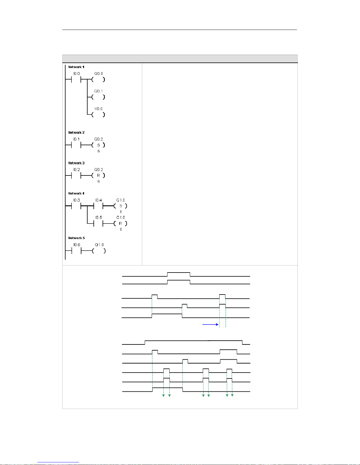
S7-200 Programmable Controller System Manual
74
Example: Coil Instructions
Network 1 //Output instructions assign bit values to external I/O (I, Q)
//and internal memory (M, SM, T, C, V, S, L).
LD I0.0
=Q0.0
=Q0.1
=V0.0
Network 2 //Set a sequential group of 6 bits to a value of 1. Specify a
//starting bit address and how many bits to set. The program
//status indicator for Set is ON when the value of the first bit
//(Q0.2) is 1.
LD I0.1
S Q0.2, 6
Network 3 //Reset a sequential group of 6 bits to a value of 0.
//Specify a starting bit address and how many bits to reset.
//The program status indicator for Reset is ON when the value
//of the first bit (Q0.2) is 0.
LD I0.2
R Q0.2, 6
Network 4 //Sets and resets 8 output bits (Q1.0 to Q1.7) as a group.
LD I0.3
LPS
AI0.4
S Q1.0, 8
LPP
AI0.5
R Q1.0, 8
Network 5 //The Set and Reset instructions perform the function of a latched
//relay. To isolate the Set/Reset bits, make sure they are not
//overwritten by another assignment instruction. In this example,
//Network 4 sets and resets eight output bits (Q1.0 to Q1.7)
//as a group. In RUN mode, Network 5 can overwrite
//the Q1.0 bit value andcontroltheSet/Reset program
//status indicators in Network 4.
LD I0.6
=Q1.0
I0.0
Q0.0, Q0.1, V0.0
I0.1 (Set)
I0.2 (Reset)
Network 1
Networks 2 and 3
Networks 4 and 5
I0.3
I0.4 (Set)
I0.5 (Reset)
I0.6
Q1.0
Timing Diagram
Network 5Output bit(=) instruction overwritesthe first bi t (Q1.0) Set/Reset in
Network 4because the program scan executes the Network 5 assignment last
Reset to0 overwrites Set to 1because the program scan
executes the Network 3 Reset after the Network 2Set
Page 89
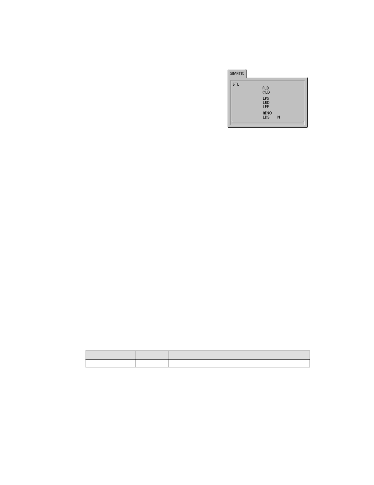
S7-200 Instruction Set Chapter 6
75
Logic Stack Instructions
AND Load
The AND Load instruction (ALD)combinesthevaluesinthe
firstand second levelsofthestackusinga logicalAND
operation.Theresult is loaded in the top of stack. Afterthe
ALD is executed, the stack depth is decreased by one.
OR Load
The OR Load instruction (OLD)combines the values in the
firstandsecond levelsofthestack,using a logicalOR
operation.Theresult is loaded in the top of the stack. After
the OLD is executed, the stack depth is decreased by one.
Logic Push
The Logic Push instruction(LPS)duplicates the top value on the stack and pushes this value onto
the stack. The bottomofthestackispushed off and lost.
Logic Read
The Logic Read instruction(LRD)copies the second stack value to the top of stack.The stack is
not pushed or popped, but the old top-of-stack value is destroyed by the copy.
Logic Pop
The Logic Pop instruction(LPP)popsone value off of the stack. The second stack value becomes
the new top of stack value.
AND ENO
The AND ENO instruction (AENO)performs a logicalANDoftheENObitwith the top of the stack
to generate the same effect as the ENO bit of a box in LAD or FBD. The result of the AND
operationisthenew top ofstack.
ENO is a Boolean output for boxes in LAD and FBD. If a box has power flow at the EN input and
is executed without error,the ENO output passes power flowtothenextelement. You can use the
ENO as an enable bit that indicates the successfulcompletion of an instruction. The ENO bit is
used with the top of stack to affect power flow forexecution of subsequent instructions. STL
instructions do not have an EN input. The top of the stack must be a logic 1 for conditional
instructions to be executed. In STL there is also no ENO output.However, the STL instructions
that correspondtoLAD and FBD instructions withENO outputsseta specialENO bit.This bit is
accessible withtheAENO instruction.
Load Stack
The Load Stack instruction(LDS)duplicates the stack bit (N)onthestackand places thisvalue
on top of the stack. The bottom of thestackispushed offand lost.
Table 6-5 Valid Operands for the Load Stack Instruction
Inputs/Outputs Data Type Operands
N BYTE Constant (0 to 8)
Page 90
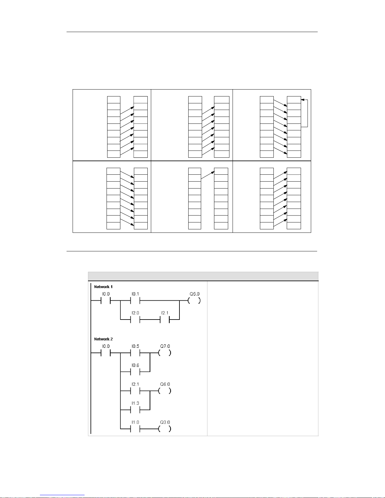
S7-200 Programmable Controller System Manual
76
As shown in Figure 6-3, the S7-200 uses a logic stack to resolve the controllogic. In these
examples, “iv0”to “iv7”identify theinitial values of the logic stack, “nv” identifies a new value
provided by the instruction, and “S0” identifies the calculated value that is stored in the logicstack.
ALD
AND the top
two stack
values
Before After
iv8
x
1
S0
iv2
iv3
iv4
iv5
iv6
iv7
iv0
iv1
iv2
iv3
iv4
iv5
iv6
iv7
iv8S0= iv0AND iv1
OLD
OR the top two
stack values
Before After
S0 =iv0 ORiv1
iv8
x
1
S0
iv2
iv3
iv4
iv5
iv6
iv7
iv0
iv1
iv2
iv3
iv4
iv5
iv6
iv7
iv8
LDS
Load Stack
iv6
iv7
iv3
iv0
iv1
iv2
iv3
iv4
iv5
iv0
iv1
iv2
iv3
iv4
iv5
iv6
iv7
iv8
2
Before A fter
LPS
Logic Push
iv6
iv7
iv0
iv0
iv1
iv2
iv3
iv4
iv5
iv0
iv1
iv2
iv3
iv4
iv5
iv6
iv7
iv8
2
Before A fter
LRD
Logic Read
Before After
iv1iv0
iv1
iv2
iv3
iv4
iv5
iv6
iv7
iv8
iv1
iv2
iv3
iv4
iv5
iv6
iv7
iv8
LPP
Logic Pop
Before After
iv8
x
1
iv1
iv2
iv3
iv4
iv5
iv6
iv7
iv0
iv1
iv2
iv3
iv4
iv5
iv6
iv7
iv8
1
The value is unknown (it could be either a 0 or a 1).
2
After the execution of a Logic Push or a Load Stack instruction, value iv8 is lost.
Figure 6-3 Operations of the Logic Stack Instructions
Example: Logic Stack Instructions
Network 1
LD I0.0
LD I0.1
LD I2.0
AI2.1
OLD
ALD
=Q5.0
Network 2
LD I0.0
LPS
LD I0.5
OI0.6
ALD
=Q7.0
LRD
LD I2.1
OI1.3
ALD
=Q6.0
LPP
AI1.0
=Q3.0
Page 91
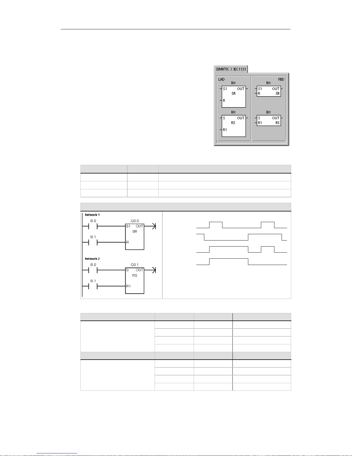
S7-200 Instruction Set Chapter 6
77
Set and Reset Dominant Bistable Instructions
The Set Dominant Bistableisa latchwherethe set
dominates.Ifthe set (S1)and reset(R)signals are both
true, theoutput(OUT) is true.
The Reset Dominant Bistableisa latchwhere the reset
dominates.Ifthe set (S)and reset(R1)signals are both
true, theoutput(OUT) is false.
The Bit parameterspecifies the Boolean parameter that is
set or reset.The optionaloutput reflects the signal state of
the Bit parameter.
Table 6-7 shows the truth tables for the sample program.
Table 6-6 Valid Operands for the Set Dominant Bistable and Reset Dominant Bistable
Instructions
Inputs/Outputs Data Types Operands
S1, R BOOL I,Q,V,M,SM,S,T,C,PowerFlow
S, R1, OUT BOOL I,Q,V,M,SM,S,T,C,L,PowerFlow
Bit BOOL I, Q, V, M,S
Example: Set and Reset Dominant Bistable Instructions
Set I0.0
Reset I0.1
SR Q0.0
RS Q0.1
Timing Diagram
Table 6-7 Truth Table for the Set and Reset Dominant Bistable Instructions
Instruction S1 R Out (Bit)
Set Dominant Bistable instruction
0 0 Previous state
(SR)
0 1 0
1 0 1
1 1 1
Instruction S R1 Out (Bit)
Reset Dominant Bistable instruction
0 0 Previous state
(RS)
0 1 0
1 0 1
1 1 0
Page 92
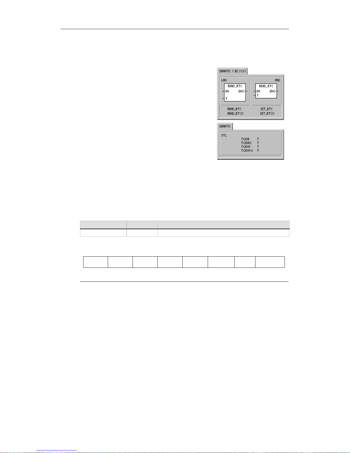
S7-200 Programmable Controller System Manual
78
Clock Instructions
Read Real-Time Clock and Set Real-Time
Clock
The Read Real-TimeClock(TODR) instruction reads the
currenttime and date from the hardware clock and loads it
in an 8-byte Timebuffer starting at address T. The Set
Real-Time Clock (TODW) instruction writes the current time
and date to the hardware clock, beginningatthe8-byte
Time buffer address specifiedbyT.
You must code all date and time values in BCD format(for
example, 16#97 for the year 1997).Figure 6-4 shows the
formatofthe8-Byte Time buffer(T).
The time-of-day (TOD) clock initializes the following date
and time afterextendedpoweroutagesorwhenmemory
has been lost:
Date: 01--Jan -- 90
Time: 00:00:00
Day of Week: Sunday
Error conditions that set ENO = 0
H 0006 (indirect address)
H 0007 (TOD data error) Set Real-Time Clock only
H 000C (clock not present)
Table 6-8 Valid Operands for the Clock Instructions
Inputs/Outputs Data Types Operands
T BYTE IB, QB, VB, MB, SMB, SB,LB,*VD, *LD, *AC
Year:
00 to 99
Month:
01 to 12
Day:
01 to 31
Hours:
00 to 23
Minutes:
00 to 59
Seconds:
00 to 59
0
Day of Week:
0to7*
T T+1 T+2 T+3 T+4 T+6T+5 T+7
*T+7 1=Sunday,7=Saturday
0 disables the day ofweek.
Figure 6-4 Format of the 8-Byte Time Buffer (T)
Page 93

S7-200 Instruction Set Chapter 6
79
Tip
The S7-200 CPU does not perform a check to verify that the day of week is correctbased upon
the date. Invalid dates, such as February 30, could be accepted. You should ensure that the
date you enter is correct.
Do not use the TODR/TODWinstruction in both the mainprogram and in an interruptroutine. A
TODR/TODW instruction in an interruptroutine that attempts to execute while another
TODR/TODW instruction is in process cannot be executed. SM4.3 is set indicatingthat two
simultaneousaccesses to the clock wereattempted (non-fatal error 0007).
The time-of-day clock in the S7-200 uses only the least significant two digits for the year, so for
the year 2000, the year is representedas 00. The S7-200 PLC does not use the year
information in any way.However, user programs that use arithmetic or compares with the year’s
value must take into account the two-digit representation and the change in century.
Leap year is correctlyhandledthrough year 2096.
Read Real Time Clock Extended
The Read Real Time Clock Extended (TODRX)instruction
reads the currenttime, date, and daylightsavings
configuration fromthePLCand loads itina 19-bytebuffer
beginning at the address specified by T.
Error conditions that set ENO = 0
H 0006 (indirect address)
H 000C (clock cartridge not present)
H 0091 (range error)
Set Real Time Clock Extended
The Set Real Time Clock (TODWX)instruction writes the
currenttime, date, and daylightsavingsconfiguration to the
PLC beginning at the 19-byte buffer address specifiedbyT.
You must code all date and time values in BCD format(for
example, 16#02 for the year 2002).Table 6-9 shows the
formatofthe19-Byte TimeBuffer (T).
The time-of-day clock initializ es the following date and time
after extendedpoweroutagesormemory has been lost:
Error conditions that set ENO = 0
H 0006 (indirect address)
H 0007 (TOD data error)
H 000C (clock cartridge not present)
H 0091 (range error)
Date: 01--Jan--90
Time 00:00:00
Day of Week: Sunday
Tip
The only time the S7-200 CPU uses bytes 9 to18 is when the “User Specified”mode is selected
in byte 8. Otherwise,the lastvaluewritten to these bytes by STEP 7--Micro/WIN or the
SET_RTCX instruction is returned.
Page 94

S7-200 Programmable Controller System Manual
80
Table 6-9 Format of the 19-Byte Time Buffer (TI)
TByte Description Byte Data
0 year (0--99) current year (BCD value)
1 month (1--12) current month (BCD value)
2 day (1--31) current day (BCD value
3 hour (0--23) current hour (BCD value)
4 minute (0--59) current minute (BCD value)
5 second (0--59) current second (BCD value)
6 00 reserved -- always set to 00
7 day of week (1--7) current day of the week, 1=Sunday (BCD value)
8 mode (00H--03H, 08H,
10H--13H, FFH)
correction mode:
00H = correction disabled
01H = EU (time zone offset from UTC = 0 hrs)
1
02H = EU (time zone offset from UTC = +1 hrs)
1
03H = EU (time zone offset from UTC = +2 hrs)
1
04H--07H = reserved
08H = EU (time zone offset from UTC = --1 hrs)
1
09H--0FH = reserved
10H = US
2
11H = Australia
3
12H = Australia (Tasmania)
4
13H = New Zealand
5
14H--FEH = reserved
FFH = user specified (using values in bytes 9--18)
9 correction hours (0--23) correction amount, hours (BCD value)
10 correction minutes (0--59) correction amount, minutes (BCD value)
11 beginning month (1--12) beginning month of daylight saving time (BCD value)
12 beginning day (1--31) beginning day of daylight saving time (BCD value)
13 beginning hour (0--23) beginning hour of daylight saving time (BCD value)
14 beginning minute (0--59) beginning minute of daylight saving time (BCD value)
15 ending month (1--12) ending month of daylight saving time (BCD value)
16 ending day (1--31) ending day of daylight saving time (BCD value)
17 ending hour (0--23) ending hour of daylight saving time (BCD value
18 ending minute (0--59) ending minute of daylight saving time (BCD value)
1
EUconvention: Adjust timeaheadonehour onlastSunday inMarchat1:00 a.m.UTC. Adjusttime backone houron last Sunday
in October at 2:00 a.m UTC. (The local timewhen the correction is madedepends upon the time zone offsetfrom UTC).
2
US convention: Adjust time ahead onehour on first Sunday in April at2:00 a.m local time. Adjust timeback one hour on last
Sunday in October at2:00 a.m local time.
3
Australia convention: Adjust time ahead onehour onlast Sunday inOctober at 2:00a.m. localtime. Adjust timeback onehour
on last Sundayin March at 3:00 a.m.local time.
4
Australia(Tasmania)convention: Adjusttimeahead one houron firstSunday in Octoberat 2:00a.m.local time.Adjust timeback
one hour onlast Sunday in March at3:00 a.m. local time
5
New Zealandconvention: Adjust time aheadone houron first Sundayin October at 2:00a.m. local time. Adjust time back one
hour on first Sunday on or after March 15at 3:00 a.m. local time
Page 95
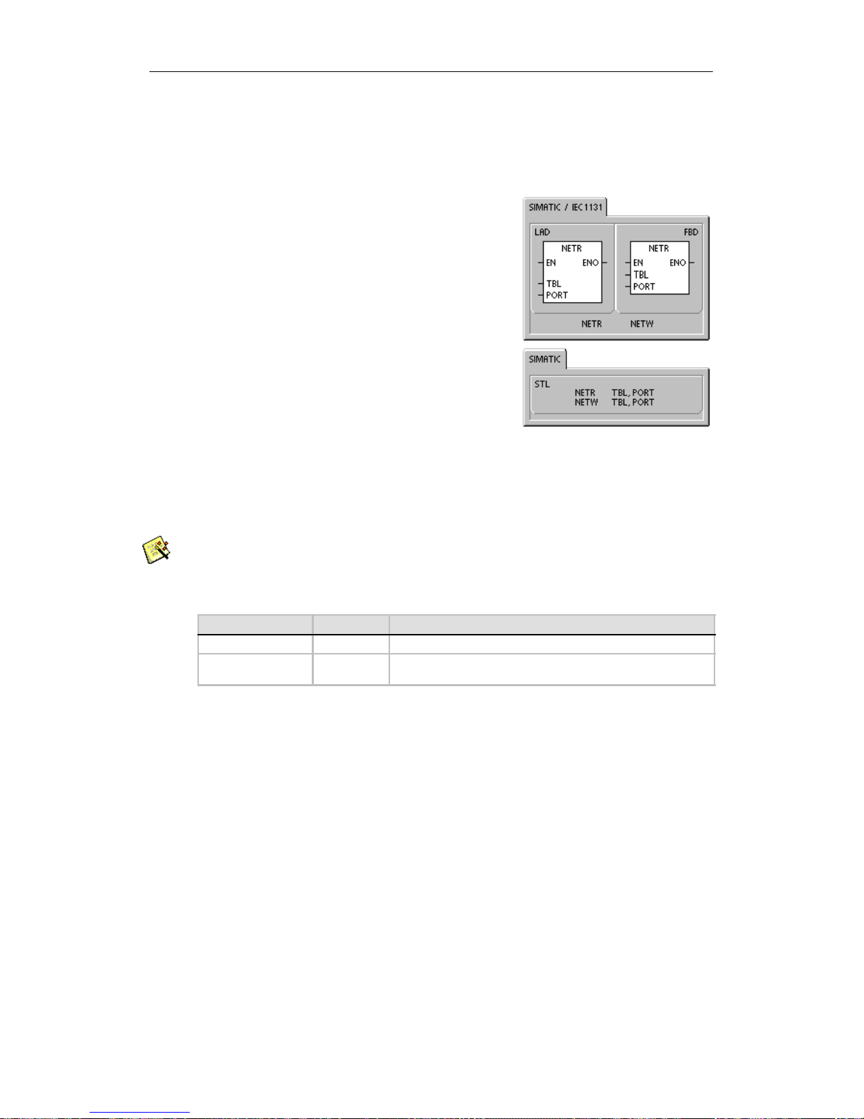
S7-200 Instruction Set Chapter 6
81
Communications Instructions
Network Read and Network Write Instructions
The Network Read instruction (NETR) initiates a
communicationsoperation to gather data from a remote
device through the specifiedport (PORT),as defined by the
table (TBL).TheNetwork Write instruction (NETW) initiates
a communications operation to write data to a remote
device through the specifiedport (PORT),as defined by the
table (TBL).
Error conditions that set ENO = 0:
H 0006 (indirect address)
H If the function returns an error and sets the E bit oftablestatus
byte (see Figure 6-5)
The Network Read instruction can read up to 16 bytes of
information from a remote station, and the Network Write
instructioncanwriteupto16bytesofinformationtoa
remote station.
You can have any number of Network Read and Network
Write instructions in the program,but only a maximumof
eight NetworkRead and NetworkWrite instructions can be
activated atany one time.Forexample, you can have 4
Network Read and 4 Network Write instructions, or 2
Network Read and 6 Network Write instructions, active at
the same time in a given S7-200.
You can use the Network Read/Network Write Instruction Wizard to configure the counter. To start
the Network Read/Network Write Instruction Wizard,selectthe Tools > Instruction Wizard menu
command and then select Network Read/Network Write fromtheInstruction Wizard window.
Table 6-10 Valid Operands for the Network Read and Network Write Instructions
Inputs/Outputs Data Type Operands
TBL BYTE VB, MB, *VD, *LD,*AC
PORT BYTE Constant for CPU 221, CPU 222, CPU 224: 0
for CPU 224XP,CPU 226: 0or1
Instruction
Wizard
Page 96
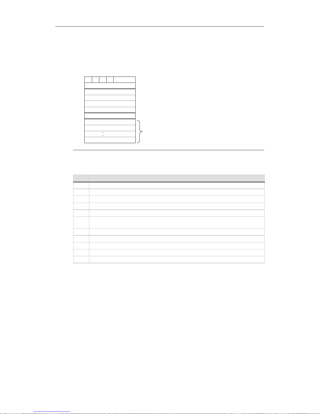
S7-200 Programmable Controller System Manual
82
Figure 6-5 describesthetable that is referencedby the TBL parameter, and Table 6-11 lists the
errorcodes.
Remote station address
Pointer to the data
area in the
remote station
(I,Q,M,orV)
Data length
Data byte 0
Data byte 15
D A E 0 Error code
70
Byte
Offset
0
1
2
3
4
5
6
7
8
22
D Done (
f
unction has been completed): 0 = not done 1 = done
A Active (function has been queued): 0 = not active 1 = active
E Error (function returnedan error): 0 = noerror 1 = error
Receive or transmit data area. 1 to 16 bytes reserved for the data.
For a Network Read instruction, stores the values that were read
from the remote station when the instruction was executed.
For a Network Write instruction, stores the values to be sent to the
remote station when the instruction is executed.
Remote station address: the address of the PLC whose data is to be
accessed.
Data byte 1
Pointer to the data area in the remote station: an indirect pointer to
the data that is to be accessed.
Data length: the number of bytes of data that are to be accessed
in the remote station (1 to 16 bytes).
Figure 6-5 TBL Parameter for the Network Read and Network Write Instructions
Table 6-11 Error Codes for the TBL Parameter
Code Definition
0 Noerror.
1 T ime-outerror: Remote station not responding.
2 Receive error: Parity, framing, or checksum error in theresponse.
3 Offlineerror: Collisions caused by duplicate station addresses or failed hardware.
4 Queue overflow error: More than 8 Network Read or Network Write instructions have been activated.
5 Protocol violation: Attempt to execute a Network Read or Network Write instruction without enabling
the PPI Master Mode in SMB30 or SMB130.
6 Illegalparameter: TBL parameter contains an illegal or invalid value.
7 No resource: Remote station is busy. (An upload or a download sequence is in process.)
8 Layer 7 error: Application protocol violation
9 Message error: Wrong data address or incorrect data length
AtoF Not used. (Reserved)
Figure 6-6 shows an example to illustrate the utility of the Network Read and Network Write
instructions. For this example, consider a production linewheretubsofbutter are being filled and
sent to one of four boxing machines (case packers).Thecase packer packs eighttubsofbutter
into a single cardboardbox.A diverter machine controls the flow of buttertubstoeach ofthecase
packers. Four S7-200s controlthe case packers, and an S7-200 with a TD 200 operator interface
controls thediverter.
Page 97
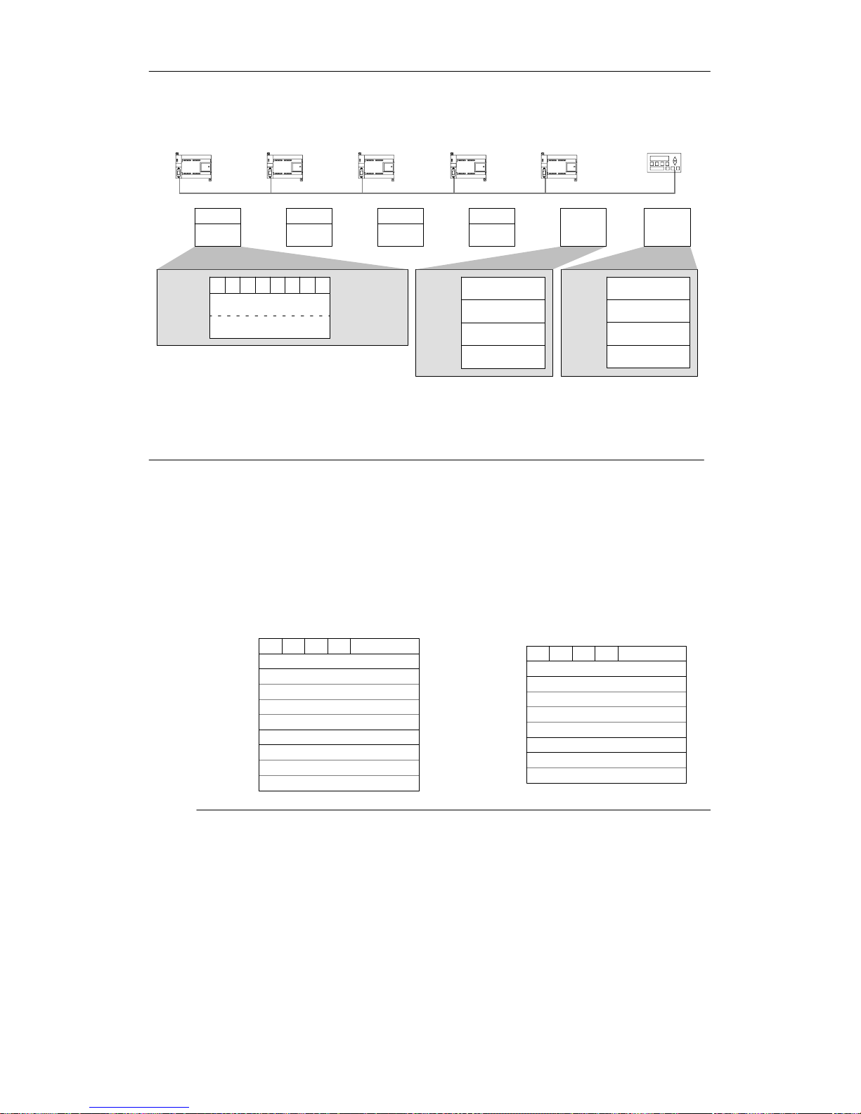
S7-200 Instruction Set Chapter 6
83
Case Packer#2
Station 3
Case Packer#3
Station 4
Case Packer#4
Station 5
TD 200 Station 1
Case Packer#1
Station 2
Diverter
Station 6
VB100
VW101
Control
Status
VB100
VW101
Control
Status
VB100
VW101
Control
Status
VB100
VW101
VB200 VB300
VB200 Receive buffer
Station 2
VB300 Transmit buffer
Station 2
Rcv
Buffers
Xmt
Buffers
Control
Status
t Out of butter tubs to pack; t=1, out of butter tubs
b Box supply is low; b=1, must add boxes in the
next 30 minutes
g Glue supply is low; g=1, must add glue in the next 30 minutes
eee error code identifying the type of fault experienced
f Fault indicator; f=1, the case packer has detected an error
VB230 Receive buffer
Station 5
VB210 Receive buffer
Station 3
VB220 Receive buffer
Station 4
VB330 Transmit buffer
Station
VB310 Transmit buffer
Station
VB320 Transmit buffer
Station 4
f e e e 0 g b t
Number of
cases packed
VB100
VB101
VB102
Control
Status MSB
LSB
Figure 6-6 Example of the Network Read and Network Write Instructions
Figure 6-7 shows the receive buffer (VB200) and transmit buffer(VB300) for accessing the data in
station 2.The S7-200 uses a Network Read instruction to read the controland statusinformation
on a continuous basis from each of the case packers. Each time a case packer has packed 100
cases, the diverternotes thisand sends a message to clear the status wordusinga NetworkWrite
instruction.
Receive Bu
f
ferfor
r
ead
i
ngf
rom
CasePacker#1
Transmit Buffer for clearing the count of
CasePacker#1
Remote station address = 2
Pointer to the
data area
in the
Remote station = (&VB101)
Data length = 2 bytes
0
D A E 0 Error Code
70
VB300
VB301
VB302
VB303
VB304
VB305
VB306
VB307
VB308
0
Remote station address = 2
Pointer to the
data area
in the
Remote station = (&VB100)
Data length = 3 bytes
Control
D A E 0 Error Code
70
VB200
VB201
VB202
VB203
VB204
VB205
VB206
VB207
VB208
Status (MSB)
VB209
Status (LSB)
Figure 6-7 Sample TBL Data for the Network Read/Write Example
Page 98
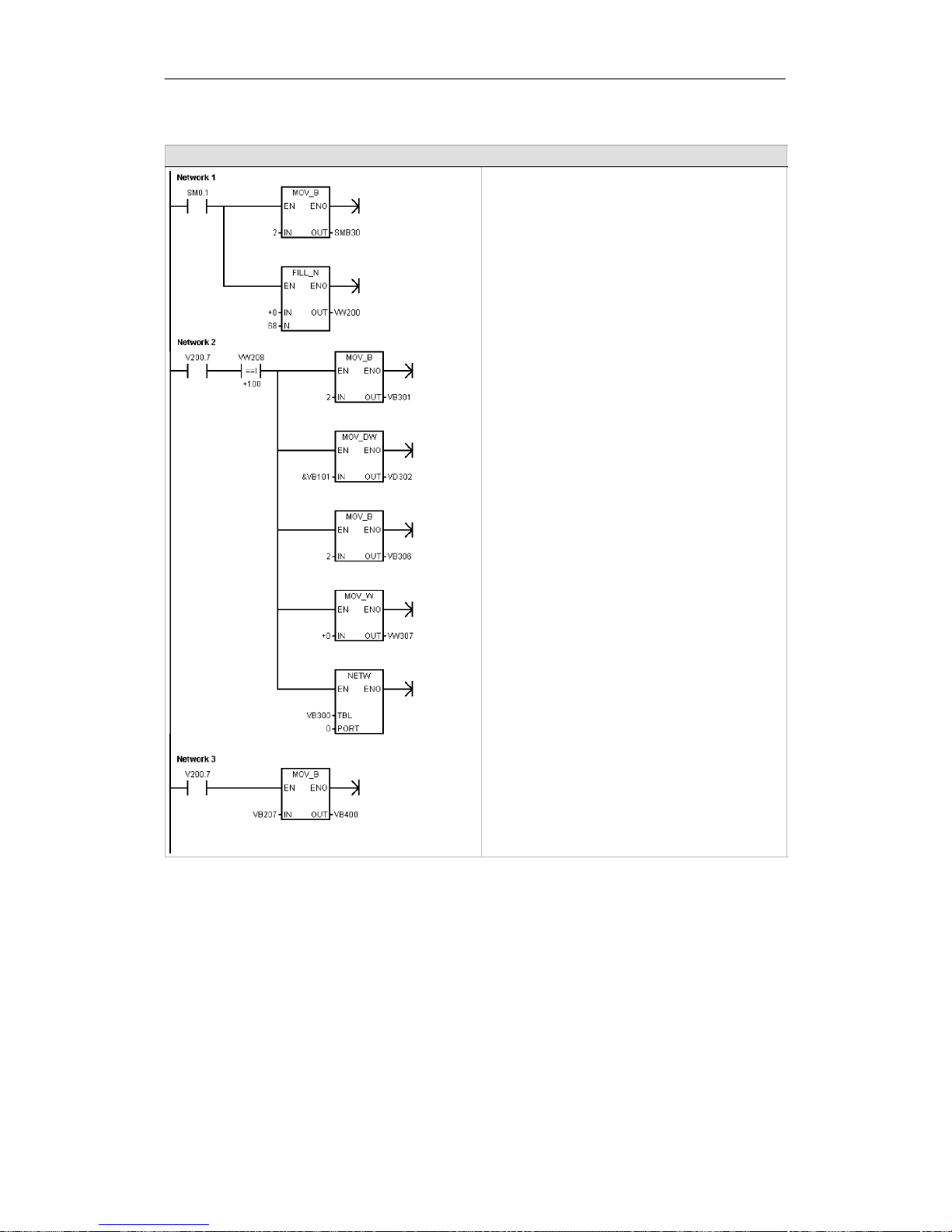
S7-200 Programmable Controller System Manual
84
Example: Network Read and Network Write Instructions
Network 1 //On the first scan, enable the
//PPI master mode
//and clear all receive and transmit buffers.
LD SM0.1
MOVB 2,SMB30
FILL +0, VW200, 68
Network 2 //When the NETR Done bit (V200.7)
//is set and 100 cases have been
//packed:
//1. Load the station address of
// case packer#1.
//2. Load a pointer to the data in
// the remotestation.
//3. Load the length of data to be
// transmitted.
//4. Load the data to transmit.
//5. Reset the number of cases packed
// by case packer #1
LD V200.7
AW= VW208, +100
MOVB 2, VB301
MOVD &VB101, VD302
MOVB 2, VB306
MOVW +0, VW307
NETW VB300, 0
Network 3 //When the NETR Done bit is set,
//save the control data from
//case packer #1.
LD V200.7
MOVB VB207, VB400
Page 99
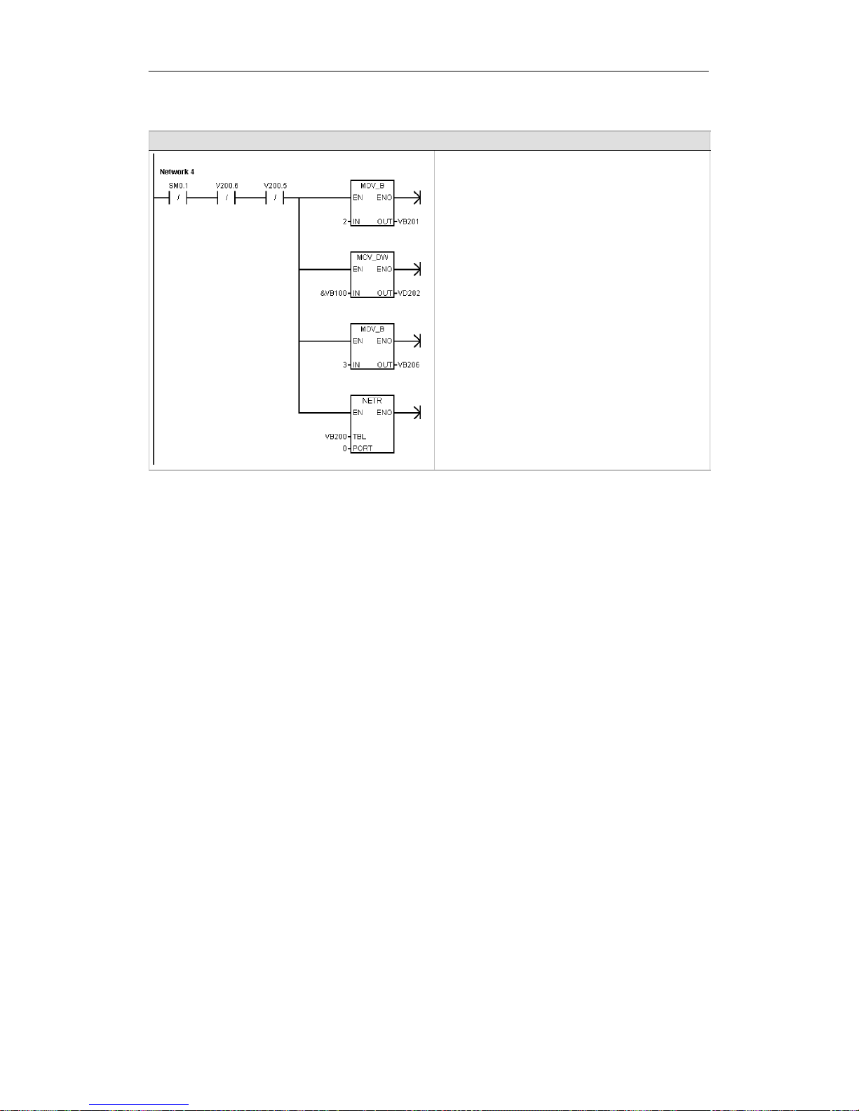
S7-200 Instruction Set Chapter 6
85
Example: Network Read and Network Write Instructions ,continued
Network 4 //If not the first scan and there are
//no errors:
//1. Load the station address of
// case packer#1.
//2. Load a pointer to the data in
// the remotestation.
//3. Load the length of data to
// be received.
//4. Read the control and status data
// in case packer #1.
LDN SM0.1
AN V200.6
AN V200.5
MOVB 2, VB201
MOVD &VB100, VD202
MOVB 3, VB206
NETR VB200, 0
Page 100
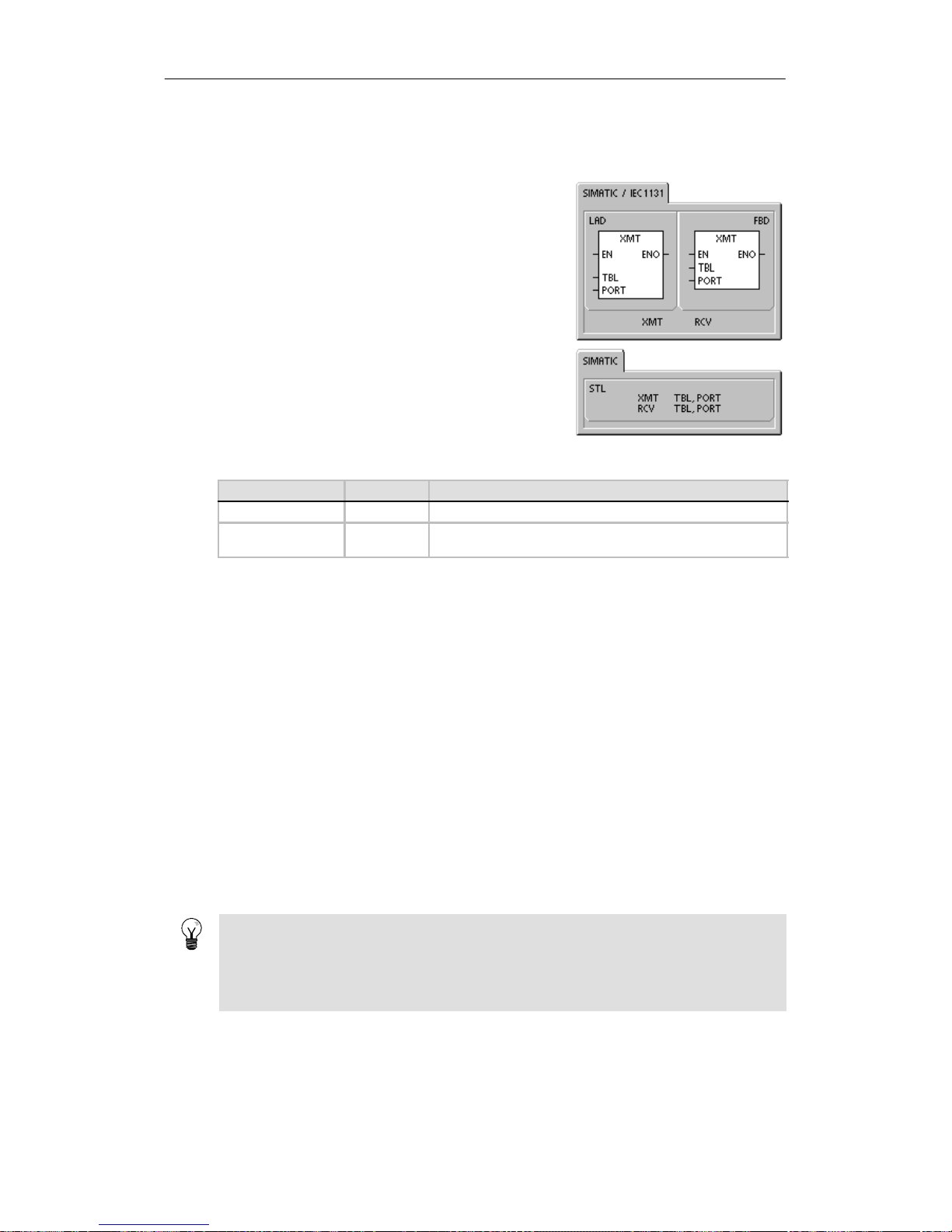
S7-200 Programmable Controller System Manual
86
Tran smit and Receive Instructions (Freeport)
The Transmitinstruction (XMT) is used in Freeport mode to
transmitdata by means of the communications port(s).
The Receive instruction (RCV) initiates or terminates the
receive message function.You must specify a start and an
end condition fortheReceivebox to operate.Messages
received through thespecified port (PORT)are stored in the
data buffer(TBL). The first entry in the data buffer specifies
the number of bytes received.
Error conditions that set ENO = 0
H 0006 (indirect address)
H 0009 (simultaneous Transmit/Receive on port 0)
H 000B (simultaneous Transmit/Receive on port 1)
H Receive parameter error sets SM86.6 or SM186.6
H S7-200 CPU is not in Freeport mode
Table 6-12 Valid Operands for the Transmit and Receive Instructions
Inputs/Outputs Data Type Operands
TBL BYTE IB, QB, VB, MB,SMB, SB, *VD, *LD, *AC
PORT BYTE Constant for CPU 221, CPU 222, CPU 224: 0
for CPU 224XP,CPU 226: 0or1
For more information about using Freeport mode, see the section CreatingUser-Defined
Protocols withFreeport Mode on page 226 in Chapter 7.
Using Freeport Mode to Control the Serial Communications Port
You can select the Freeport mode to controlthe serialcommunications port of the S7-200 by
means of the user program.Whenyou selectFreeport mode, your program controls the operation
of the communicationsportthrough the use of the receive interrupts,the transmit interrupts, the
Transmitinstruction, and the Receive instruction. The communications protocol is entirely
controlledby the ladderprogram while in Freeport mode. SMB30 (for port0)and SMB130 (forport
1 if your S7-200 has two ports) areused to selectthebaud rateandparity.
The Freeport mode is disabled and normalcommunications are re-established (for example,
programmingdeviceaccess)whentheS7-200isinSTOP mode.
In the simplestcase,you can send a message to a printer or a display using only the Transmit
(XMT) instruction. Other examples include a connection to a bar code reader, a weighingscale,
and a welder.In each case, you must write your programtosupportthe protocolthat is used by
the device with which the S7-200communicates whileinFreeport mode.
Freeportcommunications are possible only when the S7-200 is in RUN mode. Enable the
Freeport mode by settinga value of 01 in the protocolselectfield of SMB30 (Port 0) or SMB130
(Port1).While in Freeport mode, communications withtheprogramming device are not possible.
Tip
Freeportmode can be controlledusingspecialmemory bit SM0.7, which reflectsthecurrent
position of the operating mode switch.WhenSM0.7isequalto0,theswitch is in TERM
position;when SM0.7= 1, the operating mode switch is in RUN position.If you enable Freeport
mode only when the switch is in RUN position, you can use the programming device to monitor
or controltheS7-200operation by changing the switch toany otherposition.
 Loading...