

Siemens SIMATIC S7-1500,SIMATIC ET 200SP Configuration Manual

https://support.industry.siemens.com/cs/ww/de/view/109741600
Application Example 11/2016
Configuration manual
“Shared Device”
SIMATIC S7-1500 / ET 200SP

Warranty and Liability
SharedDeviceKonfig
Entry ID: 109741600, V1.0, 11/2016
2
Siemens AG 2016 All rights reserved
Warranty and Liability
Note
The Application Examples are not binding and do not claim to be complete with
regard to configuration, equipment or any contingencies. The Application
Examples do not represent customer-specific solutions. They are only intended
to provide support for typical applications. You are responsible for the correct
operation of the described products. These Application Examples do not relieve
you of the responsibility of safely and professionally using, installing, operating
and servicing equipment. When using these Application Examples, you
recognize that we cannot be made liable for any damage/claims beyond the
liability clause described. We reserve the right to make changes to these
Application Examples at any time and without prior notice. If there are any
deviations between the recommendations provided in this Application Example
and other Siemens publications – e. g. catalogs – the contents of the other
documents shall have priority.
We do not accept any liability for the information contained in this document.
Any claims against us – based on whatever legal reason – resulting from the use of
the examples, information, programs, engineering and performance data etc.,
described in this Application Example shall be excluded. Such an exclusion shall
not apply in the case of mandatory liability, e.g. under the German Product Liability
Act (“Produkthaftungsgesetz”), in case of intent, gross negligence, or injury of life,
body or health, guarantee for the quality of a product, fraudulent concealment of a
deficiency or breach of fundamental contractual obligations (“wesentliche
Vertragspflichten”). The compensation for damages due to a breach of a
fundamental contractual obligation is, however, limited to the foreseeable damage,
typical for the type of contract, except in the event of intent or gross negligence or
injury to life, body or health. The above provisions do not imply a change of the
burden of proof to your detriment.
Any form of duplication or distribution of these Application Examples or excerpts
hereof is prohibited without the expressed consent of Siemens AG.
Security
informati
on
Siemens provides products and solutions with Industrial Security functions that
support the secure operation of plants, solutions, machines, equipment and/or
networks. They are important components in a holistic Industrial Security
concept. With this in mind, Siemens’ products and solutions undergo continuous
development. Siemens recommends strongly that you regularly check for
product updates.
For the secure operation of Siemens products and solutions, it is necessary to
take suitable preventive action (e.g. cell protection concept) and integrate each
component into a holistic, state-of-the-art Industrial Security concept. Third-party
products that may be in use should also be considered. For more information
about Industrial Security, visit http://www.siemens.com/industrialsecurity.
To stay informed about product updates as they occur, sign up for a productspecific newsletter. For more information, visit
http://support.industry.siemens.com..

Table of Contents
SharedDeviceKonfig
Entry ID: 109741600, V1.0, 11/2016
3
Siemens AG 2016 All rights reserved
Table of Contents
Warranty and Liability ................................................................................................. 2
1 Task and Solution .............................................................................................. 4
1.1 Task description ................................................................................... 4
1.2 Possible solutions ................................................................................. 4
2 Fundamentals on “Shared Device” ................................................................. 6
3 Configuration ..................................................................................................... 8
3.1 Infrastructure information ..................................................................... 8
3.2 Configuring a “Shared Device” ............................................................. 9
3.2.1 Configuration of project 1 ..................................................................... 9
3.2.2 Configuration of project 2 ................................................................... 12
3.2.3 Adjusting the real time settings .......................................................... 15
3.2.4 Compiling and loading ........................................................................ 17
3.3 Diagnostics with “Shared Device” ...................................................... 18
4 References ....................................................................................................... 20
5 History............................................................................................................... 20
1 Task and Solution
SharedDeviceKonfig
Entry ID: 109741600, V1.0, 11/2016
4
Siemens AG 2016 All rights reserved
1 Task and Solution
1.1 Task description
Description
For bigger or widely dispersed plants, multiple IO controllers are frequently used.
Every peripheral module of an IO device is assigned to a particular IO controller. If
sensors spatially close to one another must send data to different IO controllers,
multiple IO devices are required.
In this configuration description, an IO device shall be assigned to multiple IO
controllers.
Requirements
The following requirements have to be considered:
Reduction of the required network and system components
Sustained reduction of engineering costs and commissioning time
Easy communication between multiple IO controllers and an IO device.
1.2 Possible solutions
Description
The function “Shared Device” allows splitting up the modules of an IO device
between different IO controllers. This distribution allows flexible automation
concepts. You have the possibility, for example, to summarize peripheral modules
spatially close to one another into one IO device.
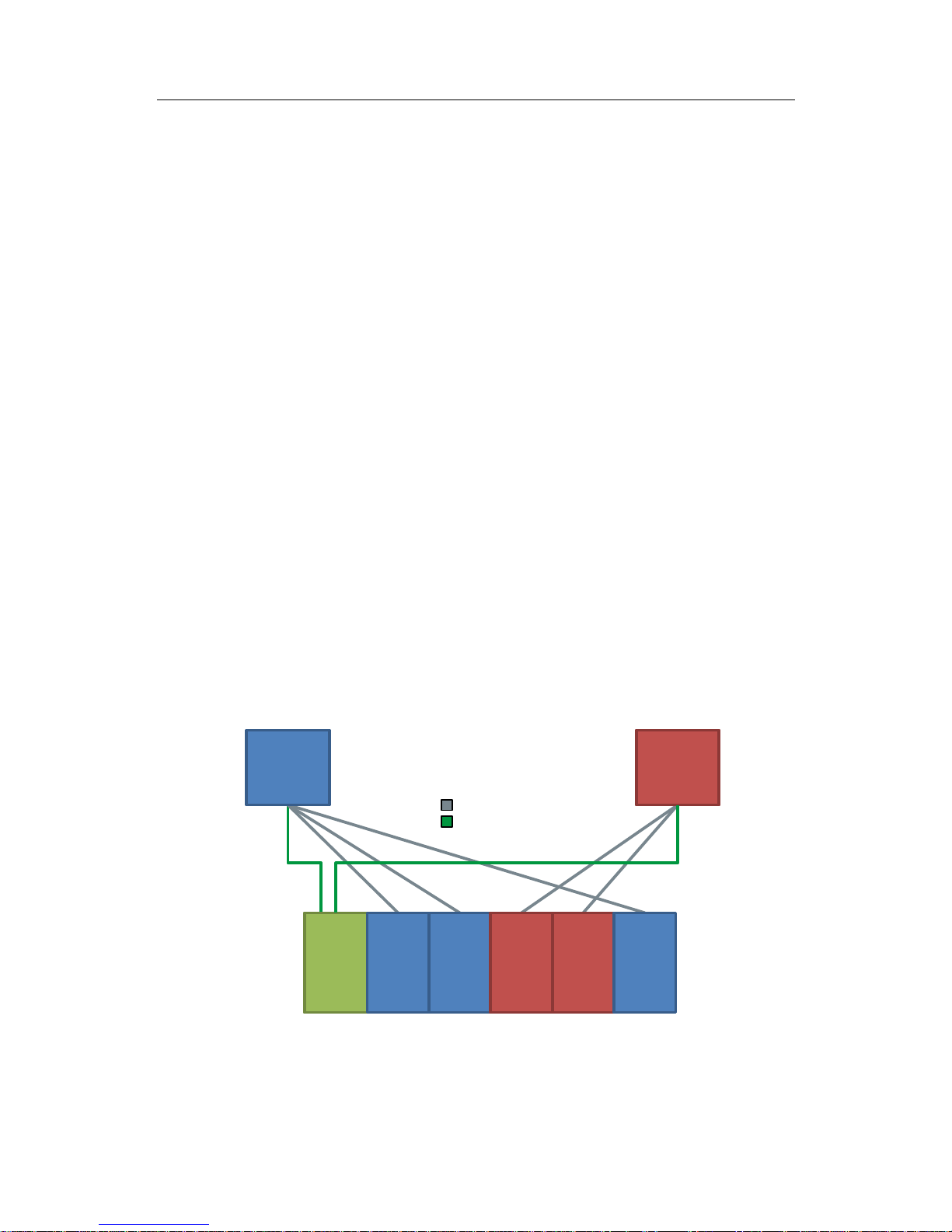
Diagrammatic representation
The following figure schematically shows the function “Shared Device”:
Figure 1-1
IO
Controller
1
IO
Controller
2
IO
Device
Module 1Module 2Module
3
Module
4
Module
5
PROFINET
Logical Assignment
Shared Device allows a shared use of IO devices via multiple IO controllers without
additional CPU-CPU communication.

1 Task and Solution
SharedDeviceKonfig
Entry ID: 109741600, V1.0, 11/2016
5
Siemens AG 2016 All rights reserved
Advantages
The solution presented here offers you the following advantages:
Lower costs through the reduction of additional IO devices and modules.
Real time capture in several CPUs.
Lower space requirements through the reduction of additional IO devices and
modules.
Lower communications burden through the suspension of CPU-CPU
communication.
No additional programming work for CPU-CPU communication.
Prerequisite
The following prerequisites must be met in order to use the “Shared Device”
function:
STEP 7 V12 SP 1 or higher
CPU as of FW 1.1 or higher as IO controller
IO device supports the “Shared Device” function
Note
IO controllers that use the “Shared Device” function, are created in different
projects.
In every project, you must ensure that the “Shared Device” is configured the
same at every station.
Characteristics with I-Device
If you use “I-Device” and the “Shared Device” function in parallel, please bear the
following conditions in mind:
A S7-1500-CPU configured as I-Device supports the “Shared Device” function
from firmware V1.5 or higher. The I-Device needs to be integrated into the IO
controller’s IO system via a GSD import.
A S7-300-CPU or a S7-400-CPU configured as I-Device supports the “Shared
Device” function. You need to export the PROFINET-GSD file for the I-Device
from STEP 7 (from V5.5 or higher) and then import it in STEP 7 (TIA Portal).
A ET 200SP-CPU configured as I-Device supports the “Shared Device”
function from firmware V1.6 or higher. The I-Device needs to be integrated into
the IO controller’s IO system via a GSD import.

2 Fundamentals on “Shared Device”
SharedDeviceKonfig
Entry ID: 109741600, V1.0, 11/2016
6
Siemens AG 2016 All rights reserved
2 Fundamentals on “Shared Device”
Explanation of terms
An IO device whose modules are used by different IO controllers is referred to as
“Shared Device”.
The access to the modules of the “Shared Device” is split up between the different
IO controllers. Every module of the “Shared Device” is exclusively assigned to a
particular IO controller.
Functionality “Shared Device”
The function “Shared Device” allows splitting up the modules of an IO device
between different IO controllers. Thereby, several IO controllers can access the
same IO device without CPU-CPU communication. You have the possibility, for
example, to summarize peripheral modules spatially close to one another into one
IO device.
Note
The “Shared Device” allows you to build up an IO device from F- and default
modules and assign each module according to the F-CPU or default CPU.
Thus, the F-CPU can control a safe F-Power module for a failsafe F-shutdown
and a robot can use the default inputs/outputs in the same station.
Access of IO controllers to “Shared Device”
In the Engineering Tool via the “Shared Device” parameter of the interface module,
it can be determined to which modules the IO controller has access to:
If the local IO controller has access to the configured module, select the IO
controller’s name from the list.
If not the local IO controller but the IO controller from another project shall have
access to the configured module, select the entry “---”. If every module in just
one project is assigned to one IO controller, then access-wise, the
configuration is consistent.
If an IO controller does not have access to a module (entry “--”), the following
consequences apply:
A data exchange with the module is not possible.
Alarms and diagnostics cannot be received, meaning that in the online view,
the diagnostic status will not be displayed.
Configuring the module is not possible.
Setting the real-time properties
STEP 7 calculates the communications burden and the resulting update times. In
order to allow a calculation for “Shared Device” configurations, you need to enter
the number of project-external IO controllers into the project where the PROFINET
interface of the “Shared Device” is assigned to the IO controller. The maximum
possible number of IO controllers for the “Shared Device” is device-dependent.
This number is stored in the GSD file of the “Shared Device”. If the IO controller is
a CPU, you can set a very short send clock. The send clock can be shorter than
the shortest sending rate supported by the “Shared Device”. In this case, the
“Shared Device” will be operated by the IO controller with a send clock that it
supports (send clock adaption).
 Loading...