

Siemens SIMATIC S7-1500,SIMATIC ET 200MP User Manual

___________________
___________________
___________________
___________________
___________________
___________________
___________________
___________________
___________________
___________________
SIMATIC
S7-1500/ET 200MP
Analog input module
AI 8xU/I/RTD/TC ST
(6ES7531-7KF00-0AB0)
Manual
09/2016
A5E03484864
-AD
Preface
Documentation guide
1
Product overview
2
Wiring
3
Parameters/address space
4
Interrupts/diagnostics alarms
5
Technical specifications
6
Dimensional drawing
A
Parameter data records
B
Representation of analog
values
C
Siemens AG
Division Digital Factory
Postfach 48 48
90026 NÜRNBERG
GERMANY
A5E03484864-AD
Ⓟ
11/2016 Subject to change
Copyright © Siemens AG 2014 - 2016.
All righ
ts reserved
Legal information
Warning notice system
This manual contains notices you have to observe in order to ensure your personal safety, as well as to prevent
damage to property. The notices referring to your personal safety are highlighted in the manual by a safety alert
symbol, notices referring only to property damage have no safety alert symbol. These notices shown below are
graded according to the degree of danger.
DANGER
indicates that death or severe personal injury will result if proper precautions are not taken.
WARNING
indicates that death or severe personal injury may result if proper precautions are not taken.
CAUTION
indicates that minor personal injury can result if proper precautions are not taken.
NOTICE
indicates that property damage can result if proper precautions are not taken.
If more than one degree of danger is present, the warning notice representing the highest degree of danger will
be used. A notice warning of injury to persons with a safety alert symbol may also include a warning relating to
property damage.
Qualified Personnel
The product/system described in this documentation may be operated only by
personnel qualified
for the specific
task in accordance with the relevant documentation, in particular its warning notices and safety instructions.
Qualified personnel are those who, based on their training and experience, are capable of identifying risks and
avoiding potential hazards when working with these products/systems.
Proper use of Siemens products
Note the following:
WARNING
Siemens products may only be used for the applications described in the catalog and in the relevant technical
documentation. If products and components from other manufacturers are used, these must be recommended
or approved by Siemens. Proper transport, storage, installation, assembly, commissioning, operation and
maintenance are required to ensure that the products operate safely and without any problems. The permissible
ambient conditions must be complied with. The information in the relevant documentation must be observed.
Trademarks
All names identified by ® are registered trademarks of Siemens AG. The remaining trademarks in this publication
may be trademarks whose use by third parties for their own purposes could violate the rights of the owner.
Disclaimer of Liability
We have reviewed the contents of this publication to ensure consistency with the hardware and software
described. Since variance cannot be precluded entirely, we cannot guarantee full consistency. However, the
information in this publication is reviewed regularly and any necessary corrections are included in subsequent
editions.

Analog input module AI 8xU/I/RTD/TC ST (6ES7531-7KF00-0AB0)
4 Manual, 09/2016, A5E03484864-AD
Preface
Purpose of the documentation
This manual supplements the system manual S7-1500/ET 200MP
(https://support.industry.siemens.com/cs/ww/en/view/59191792
).
Functions that relate in general to the systems are described in this system manual.
The information provided in this manual and in the system/function manuals supports you in
commissioning the systems.
Changes compared to previous version
Compared to the previous version, this manual contains the following change:
Original texts of the license conditions and copyright notes for open-source software are
available on the Internet as of 09/2016.
Conventions
The term "CPU" is used in this manual both for the CPUs of the S7-1500 automation system,
as well as for interface modules of the ET 200MP distributed I/O system.
Please also observe notes marked as follows:
Note
A note contains important information on the product described in the documentation, on the
handling of the product or on the section of the documentation to which particular attention
should be pai
d.

Preface
Analog input module AI 8xU/I/RTD/TC ST (6ES7531-7KF00-0AB0)
Manual, 09/2016, A5E03484864-AD
5
Security information
Siemens provides products and solutions with industrial security functions that support the
secure operation of plants, systems, machines and networks.
In order to protect plants, systems, machines and networks against cyber threats, it is
necessary to implement – and continuously maintain – a holistic, state-of-the-art industrial
security concept. Siemens’ products and solutions only form one element of such a concept.
Customer is responsible to prevent unauthorized access to its plants, systems, machines
and networks. Systems, machines and components should only be connected to the
enterprise network or the internet if and to the extent necessary and with appropriate security
measures (e.g. use of firewalls and network segmentation) in place.
Additionally, Siemens’ guidance on appropriate security measures should be taken into
account. For more information about industrial security, please visit
(http://www.siemens.com/industrialsecurity
).
Siemens’ products and solutions undergo continuous development to make them more
secure. Siemens strongly recommends to apply product updates as soon as available and to
always use the latest product versions. Use of product versions that are no longer supported,
and failure to apply latest updates may increase customer’s exposure to cyber threats.
To stay informed about product updates, subscribe to the Siemens Industrial Security RSS
Feed under (http://www.siemens.com/industrialsecurity
).
Open Source Software
Open-source software is used in the firmware of the I/O modules. Open Source Software is
provided free of charge. We are liable for the product described, including the open-source
software contained in it, pursuant to the conditions applicable to the product. Siemens
accepts no liability for the use of the open source software over and above the intended
program sequence, or for any faults caused by modifications to the software.
For legal reasons, we are obliged to publish the original text of the license conditions and
copyright notices. Please read the information relating to this on the Internet
(https://support.industry.siemens.com/cs/ww/en/view/109741045
).

Analog input module AI 8xU/I/RTD/TC ST (6ES7531-7KF00-0AB0)
6 Manual, 09/2016, A5E03484864-AD
Table of contents
Preface ................................................................................................................................................... 4
1 Documentation guide .............................................................................................................................. 7
2 Product overview .................................................................................................................................. 11
2.1 Properties ............................................................................................................................... 11
3 Wiring ................................................................................................................................................... 14
4 Parameters/address space ................................................................................................................... 22
4.1 Measuring types and ranges .................................................................................................. 22
4.2 Parameters ............................................................................................................................. 25
4.3 Declaration of parameters ...................................................................................................... 27
4.4 Address space ....................................................................................................................... 31
5 Interrupts/diagnostics alarms................................................................................................................. 37
5.1 Status and error displays ....................................................................................................... 37
5.2 Interrupts ................................................................................................................................ 39
5.3 Diagnostics alarms ................................................................................................................. 41
6 Technical specifications ........................................................................................................................ 42
A Dimensional drawing ............................................................................................................................. 49
B Parameter data records ........................................................................................................................ 51
B.1 Parameter assignment and structure of the parameter data records .................................... 51
B.2 Structure of a data record for dynamic reference temperature .............................................. 62
C Representation of analog values ........................................................................................................... 64
C.1 Representation of input ranges .............................................................................................. 65
C.2 Representation of analog values in voltage measuring ranges ............................................. 66
C.3 Representation of analog values in the current measuring ranges ....................................... 67
C.4 Representation of the analog values of resistance-based sensors/resistance
thermometers ......................................................................................................................... 68
C.5 Representation of analog values for thermocouples ............................................................. 71
C.6 Measured values for wire break diagnostic ........................................................................... 74
Analog input module AI 8xU/I/RTD/TC ST (6ES7531-7KF00-0AB0)
Manual, 09/2016, A5E03484864-AD
7
1
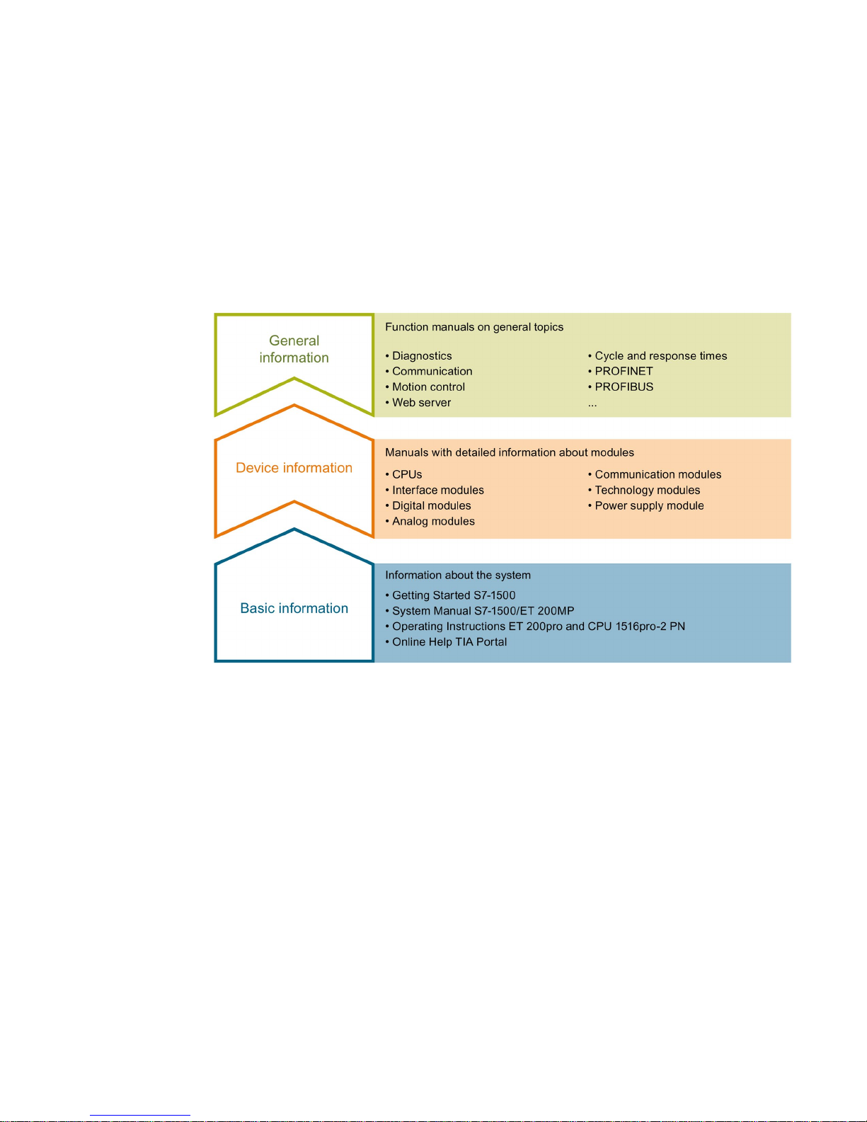
The documentation for the SIMATIC S7-1500 automation system, the CPU 1516pro-2 PN
based on SIMATIC S7-1500 and the SIMATIC ET 200MP distributed I/O system is arranged
into three areas.
This arrangement enables you to access the specific content you require.
Basic information
The System Manual and Getting Started describe in detail the configuration, installation,
wiring and commissioning of the SIMATIC S7-1500 and ET 200MP systems. For
CPU 1516pro-2 PN you use the corresponding operating instructions. The STEP 7 online
help supports you in the configuration and programming.
Device information
Product manuals contain a compact description of the module-specific information, such as
properties, wiring diagrams, characteristics and technical specifications.

Documentation guide
Analog input module AI 8xU/I/RTD/TC ST (6ES7531-7KF00-0AB0)
8 Manual, 09/2016, A5E03484864-AD
General information
The function manuals contain detailed descriptions on general topics regarding the SIMATIC
S7-1500 and ET 200MP systems, e.g. diagnostics, communication, motion control, Web
server, OPC UA.
You can download the documentation free of charge from the Internet
(
http://w3.siemens.com/mcms/industrial-automation-systems-simatic/en/manual-
overview/Pages/Default.aspx).
Changes and supplements to the manuals are documented in a Product Information.
You can download the product information free of charge from the Internet
(https://support.industry.siemens.com/cs/us/en/view/68052815
).
Manual Collection S7-1500/ET 200MP
The Manual Collection contains the complete documentation on the SIMATIC S7-1500
automation system and the ET 200MP distributed I/O system gathered together in one file.
You can find the Manual Collection on the Internet
(https://support.industry.siemens.com/cs/ww/en/view/86140384
).
SIMATIC S7-1500 comparison list for programming languages
The comparison list contains an overview of which instructions and functions you can use for
which controller families.
You can find the comparison list on the Internet
(https://support.industry.siemens.com/cs/ww/en/view/86630375
).
"mySupport"
With "mySupport", your personal workspace, you make the best out of your Industry Online
Support.
In "mySupport", you can save filters, favorites and tags, request CAx data and compile your
personal library in the Documentation area. In addition, your data is already filled out in
support requests and you can get an overview of your current requests at any time.
You must register once to use the full functionality of "mySupport".
You can find "mySupport" on the Internet (https://support.industry.siemens.com/My/ww/en
).
"mySupport" - Documentation
In the Documentation area in "mySupport" you can combine entire manuals or only parts of
these to your own manual.
You can export the manual as PDF file or in a format that can be edited later.
You can find "mySupport" - Documentation on the Internet
(http://support.industry.siemens.com/My/ww/en/documentation
).

Documentation guide
Analog input module AI 8xU/I/RTD/TC ST (6ES7531-7KF00-0AB0)
Manual, 09/2016, A5E03484864-AD
9
"mySupport" - CAx data
In the CAx data area in "mySupport", you can access the current product data for your CAx
or CAe system.
You configure your own download package with a few clicks.
In doing so you can select:
● Product images, 2D dimension drawings, 3D models, internal circuit diagrams, EPLAN
macro files
● Manuals, characteristics, operating manuals, certificates
● Product master data
You can find "mySupport" - CAx data on the Internet
(http://support.industry.siemens.com/my/ww/en/CAxOnline
).
Application examples
The application examples support you with various tools and examples for solving your
automation tasks. Solutions are shown in interplay with multiple components in the system separated from the focus on individual products.
You will find the application examples on the Internet
(https://support.industry.siemens.com/sc/ww/en/sc/2054
).
TIA Selection Tool
With the TIA Selection Tool, you can select, configure and order devices for Totally
Integrated Automation (TIA).
This tool is the successor of the SIMATIC Selection Tool and combines the known
configurators for automation technology into one tool.
With the TIA Selection Tool, you can generate a complete order list from your product
selection or product configuration.
You can find the TIA Selection Tool on the Internet
(http://w3.siemens.com/mcms/topics/en/simatic/tia-selection-tool
).

Documentation guide
Analog input module AI 8xU/I/RTD/TC ST (6ES7531-7KF00-0AB0)
10 Manual, 09/2016, A5E03484864-AD
SIMATIC Automation Tool
You can use the SIMATIC Automation Tool to run commissioning and maintenance activities
simultaneously on various SIMATIC S7 stations as a bulk operation independently of the TIA
Portal.
The SIMATIC Automation Tool provides a multitude of functions:
● Scanning of a PROFINET/Ethernet network and identification of all connected CPUs
● Address assignment (IP, subnet, gateway) and station name (PROFINET device) to a
CPU
● Transfer of the date and the programming device/PC time converted to UTC time to the
module
● Program download to CPU
● Operating mode switchover RUN/STOP
● Localization of the CPU by means of LED flashing
● Reading out CPU error information
● Reading the CPU diagnostic buffer
● Reset to factory settings
● Updating the firmware of the CPU and connected modules
You can find the SIMATIC Automation Tool on the Internet
(https://support.industry.siemens.com/cs/ww/en/view/98161300
).
PRONETA
With SIEMENS PRONETA (PROFINET network analysis), you analyze the PROFINET
network during commissioning. PRONETA features two core functions:
● The topology overview independently scans PROFINET and all connected components.
● The IO check is a fast test of the wiring and the module configuration of a system.
You can find SIEMENS PRONETA on the Internet
(https://support.industry.siemens.com/cs/ww/en/view/67460624
).
Analog input module AI 8xU/I/RTD/TC ST (6ES7531-7KF00-0AB0)
Manual, 09/2016, A5E03484864-AD
11
2
2.1
Properties
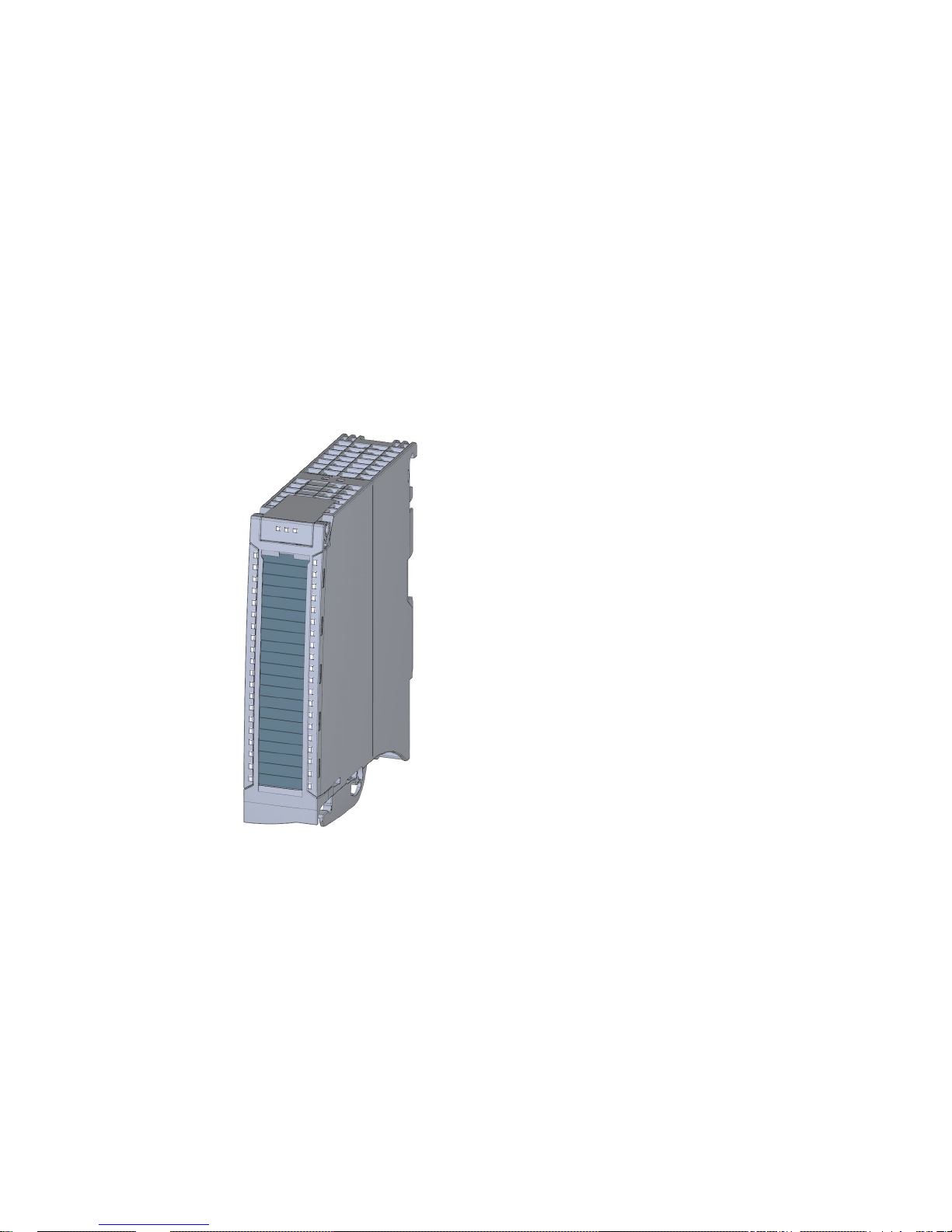
Article number
6ES7531-7KF00-0AB0
View of the module
Figure 2-1 View of the AI 8xU/I/RTD/TC ST module

Product overview
2.1 Properties
Analog input module AI 8xU/I/RTD/TC ST (6ES7531-7KF00-0AB0)
12 Manual, 09/2016, A5E03484864-AD
Properties
The module has the following technical properties:
● 8 analog inputs
● Voltage measurement type can be set per channel
● Current measurement type can be set per channel
● Measuring type resistance adjustable for channel 0, 2, 4 and 6
● Measuring type resistance thermometers (RTD) adjustable for channel 0, 2, 4 and 6
● Thermocouple (TC) measurement type can be set per channel
● Resolution 16 bits including sign
● Configurable diagnostics (per channel)
● Hardware interrupt on limit violation can be set per channel (two low and two high limits
per channel)
The module supports the following functions:
Table 2- 1 Version dependencies of the module functions
Function
Firmware version of
the module
Configuration software
STEP 7
(TIA Portal)
GSD file in STEP 7
(TIA Portal) V12 or higher, or
STEP 7 V5.5 SP3 or higher
Firmware update
V1.0.0 or higher
V12 or higher
X
Identification data I&M0 to I&M3
V1.0.0 or higher
V12 or higher
X
Parameter assignment in RUN V1.0.0 or higher V12 or higher X
Isochronous mode
V1.0.0 or higher
V12 or higher
---
Calibration in runtime V1.0.0 or higher V12 or higher X
Module-internal Shared Input (MSI) V2.0.0 or higher V13 Update 3 or higher
(PROFINET IO only)
X
(PROFINET IO only)
Configurable submodules / submodules for Shared Device
V2.0.0 or higher V13 Update 3 or higher
(PROFINET IO only)
X
(PROFINET IO only)
Configurable after interface module
IM 155-5 DP ST
V2.0.0 or higher V13 or higher X
You can configure the module with STEP 7 (TIA Portal) and with a GSD file.

Product overview
2.1 Properties
Analog input module AI 8xU/I/RTD/TC ST (6ES7531-7KF00-0AB0)
Manual, 09/2016, A5E03484864-AD
13
Accessories
The following accessories are supplied with the module and can also be ordered separately
as spare parts:
● Shield bracket
● Shield terminal
● Power supply element
● Labeling strips
● U connector
● Universal front door
Other components
The following component can be ordered separately:
Front connectors, including potential jumpers and cable ties
You can find additional information on accessories in the system manual S7-1500/ET 200MP
(https://support.industry.siemens.com/cs/ww/en/view/59191792
).

Analog input module AI 8xU/I/RTD/TC ST (6ES7531-7KF00-0AB0)
14 Manual, 09/2016, A5E03484864-AD
3
This section contains the block diagram of the module and outlines various connection
options.
You can find information on wiring the front connector, creating a cable shield, etc. in the
Wiring section of the system manual S7-1500/ET 200MP
(https://support.industry.siemens.com/cs/ww/en/view/59191792
).
You can find additional information on compensating the reference junction temperature in
the function manual Analog value processing
(http://support.automation.siemens.com/WW/view/en/67989094
), the structure of a data
record in the section Structure of a data record for dynamic reference temperature
(Page 62).
Note
•
You may use and combine the different wiring options for all channels.
•
Do not insert the potential jumpers supplied with the front connector.
Abbreviations used
Meaning of the abbreviations used in the following figures:
Un+/Un-
Voltage input channel n (voltage only)
Mn+/Mn-
Measuring input channel n
In+/In-
Current input channel n (current only)
I
c n
+/I
c n
-
Current output for RTD, channel n
UVn
Supply voltage at channel n for 2-wire transmitters (2WMT)
Comp+/Comp-
Compensation input
I
Comp
+/I
Comp
-
Current output for compensation
L+
Connection for supply voltage
M
Ground connection
M
ANA
Reference potential of the analog circuit
Wiring
Analog input module AI 8xU/I/RTD/TC ST (6ES7531-7KF00-0AB0)
Manual, 09/2016, A5E03484864-AD
15
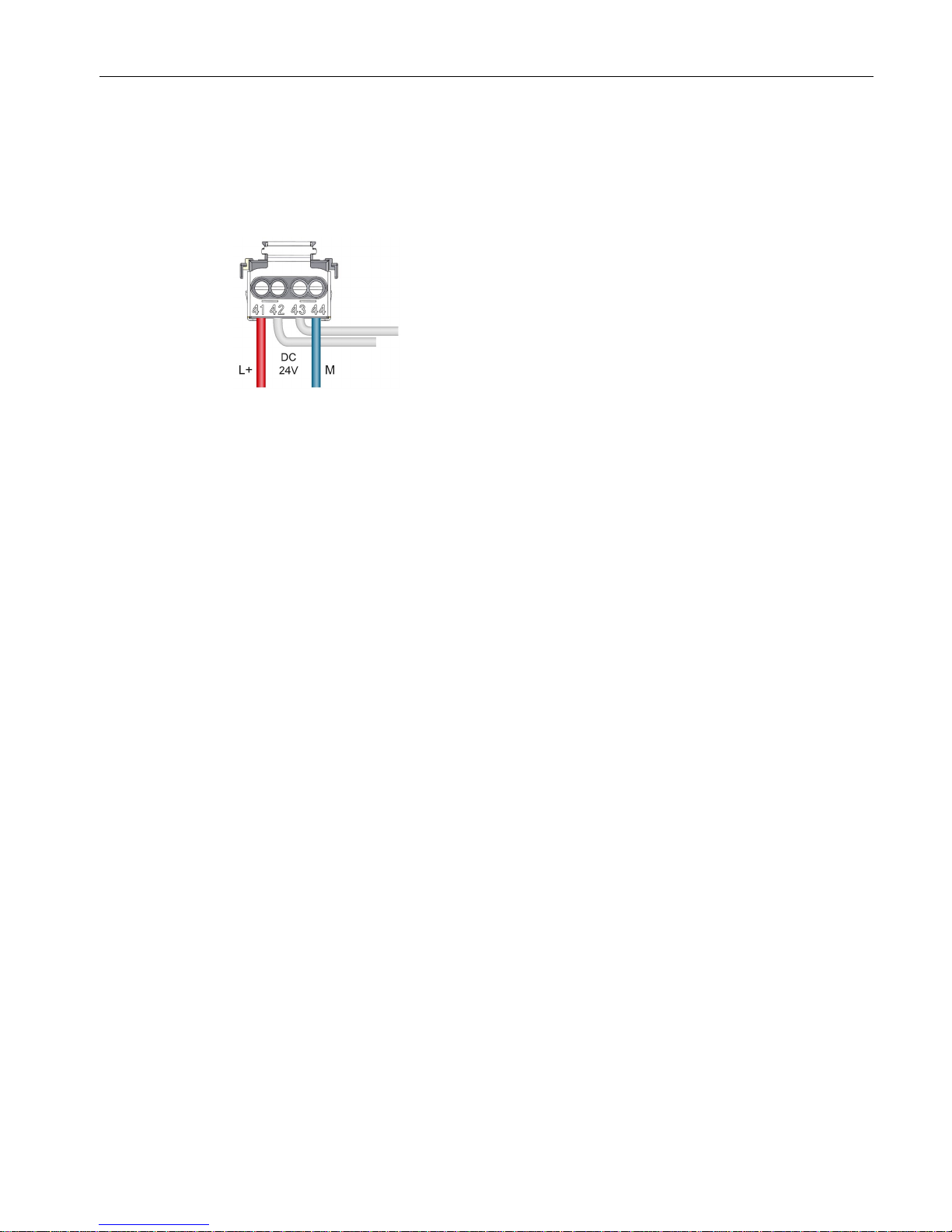
Pin assignment for the power supply element
The power supply element is plugged onto the front connector for powering the analog
module. Wire the supply voltage to terminals 41 (L+) and 44 (M). You can use terminals 42
(L+) and 43 (M) to loop the potential to the next module.
Figure 3-1 Power supply element wiring
Wiring
Analog input module AI 8xU/I/RTD/TC ST (6ES7531-7KF00-0AB0)
16 Manual, 09/2016, A5E03484864-AD
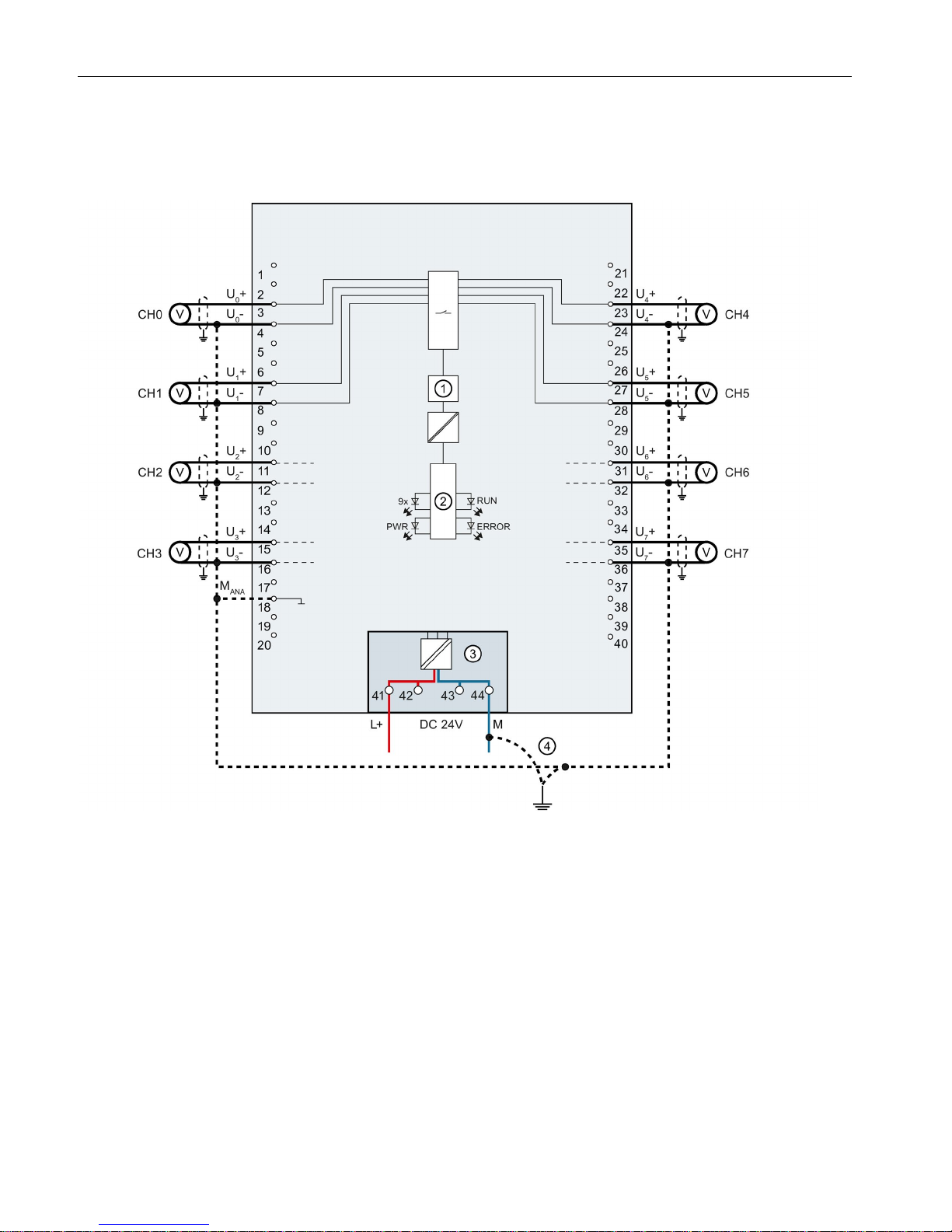
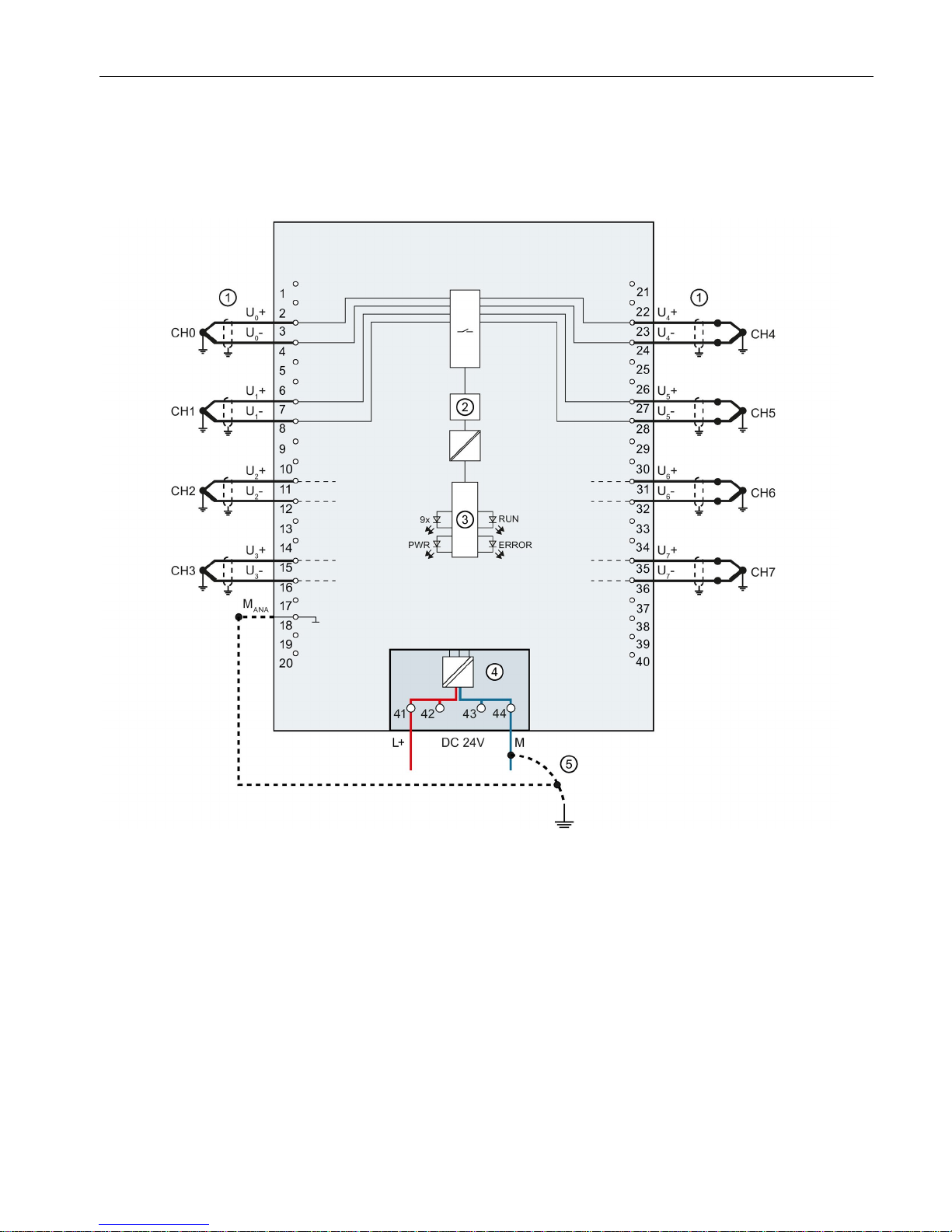
Block diagram and pin assignment for voltage measurement
The example in the following figure shows the pin assignment for voltage measurement.
①
Analog-to-digital converter (ADC)
CHx
Channel or 9 x channel status (green/red)
②
Backplane bus interface
RUN
Status display LED (green)
③
Supply voltage via power supply element
ERROR
Error display LED (red)
④
Equipotential bonding cable (optional)
PWR
LED for power supply (green)
Figure 3-2 Block diagram and pin assignment for voltage measurement
Wiring
Analog input module AI 8xU/I/RTD/TC ST (6ES7531-7KF00-0AB0)
Manual, 09/2016, A5E03484864-AD
17
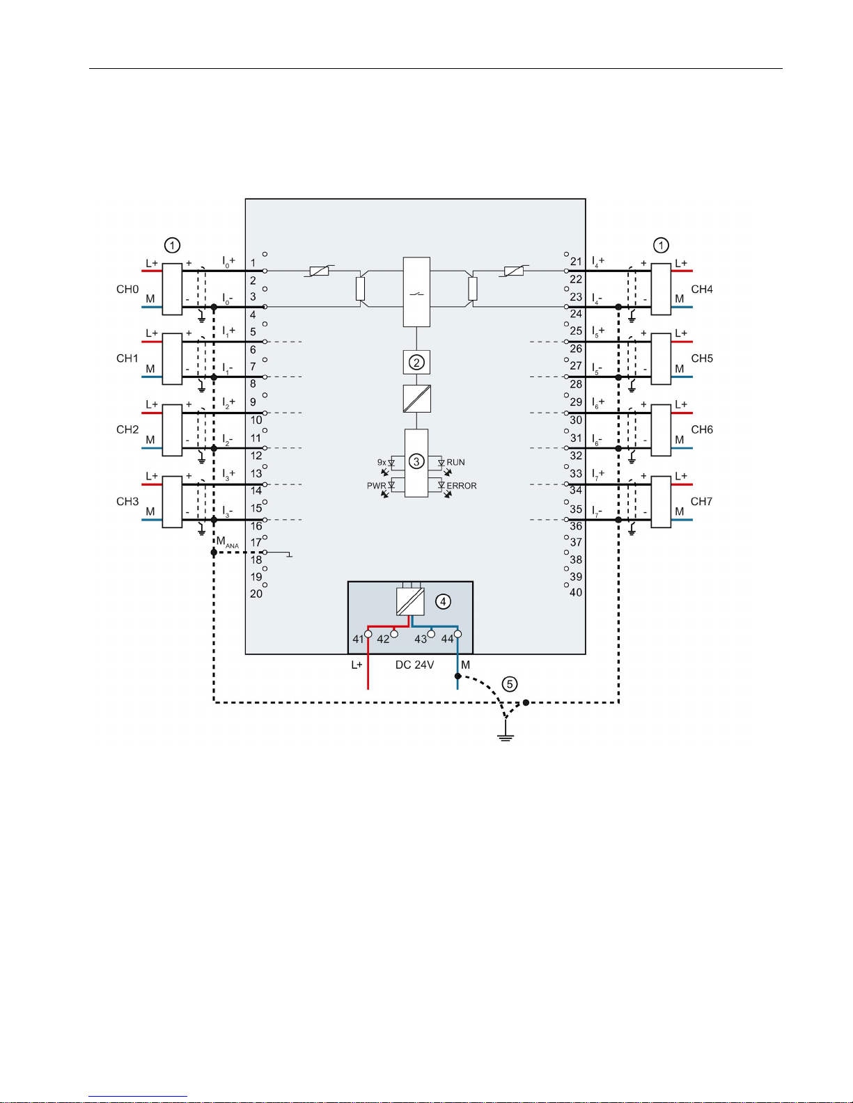
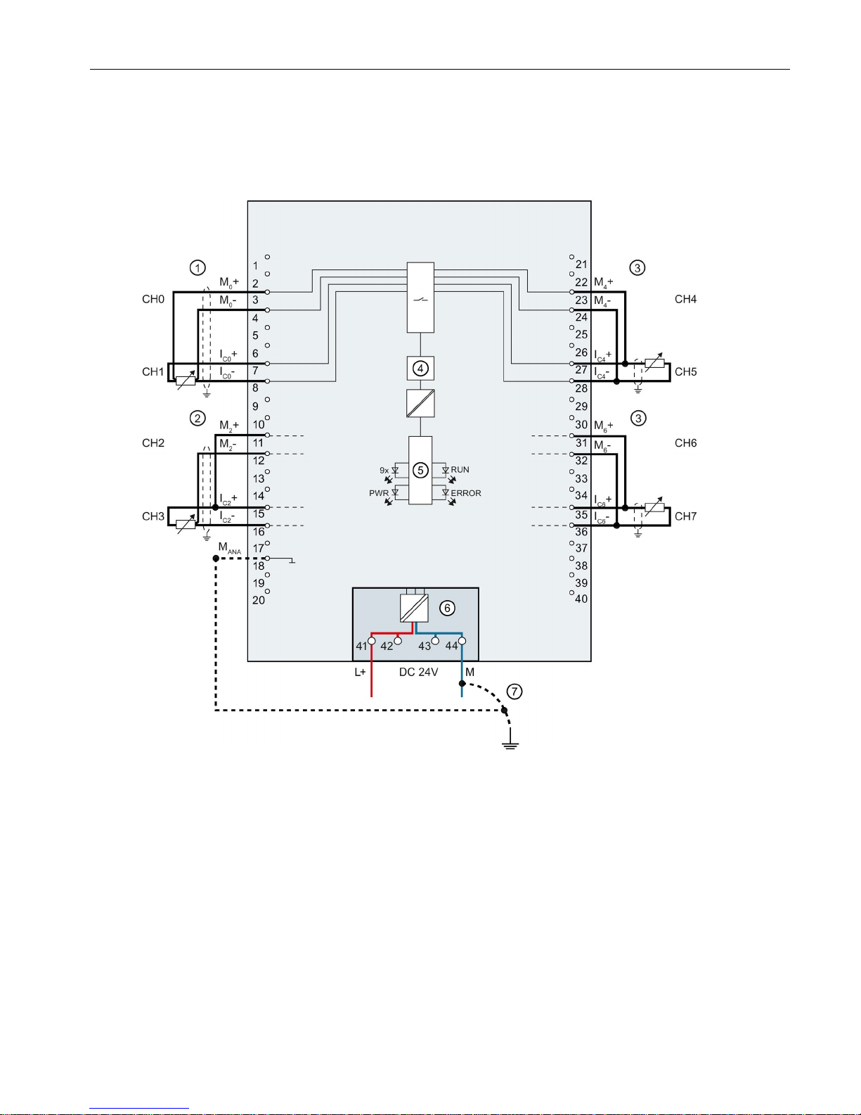
Connection: 4-wire transmitters for current measurement
The example in the following figure shows the pin assignment for current measurement with
4-wire transmitters.
①
Wiring 4-wire transmitter
CHx
Channel or 9 x channel status (green/red)
②
Analog-to-digital converter (ADC)
RUN
Status display LED (green)
③
Backplane bus interface
ERROR
Error display LED (red)
④
Supply voltage via power supply element
PWR
LED for power supply (green)
⑤
Equipotential bonding cable (optional)
Figure 3-3 Block diagram and pin assignment for current measurement
Wiring
Analog input module AI 8xU/I/RTD/TC ST (6ES7531-7KF00-0AB0)
18 Manual, 09/2016, A5E03484864-AD
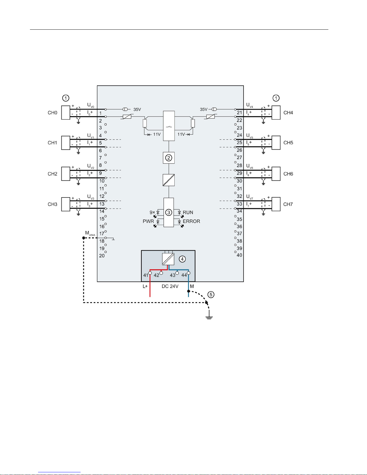
Connection: 2-wire transmitters for current measurement
The example in the following figure shows the pin assignment for current measurement with
2-wire transmitters.
①
Wiring 2-wire transmitter
CHx
Channel or 9 x channel status (green/red)
②
Analog-to-digital converter (ADC)
RUN
Status display LED (green)
③
Backplane bus interface
ERROR
Error display LED (red)
④
Supply voltage via power supply element
PWR
LED for power supply (green)
⑤
Equipotential bonding cable (optional)
Figure 3-4 Block diagram and pin assignment for current measurement
Wiring
Analog input module AI 8xU/I/RTD/TC ST (6ES7531-7KF00-0AB0)
Manual, 09/2016, A5E03484864-AD
19
Connection: 2-, 3- and 4-wire connection of resistance-based sensors or thermal resistors (RTD)
The example in the following figure shows the pin assignment for 2-, 3- and 4-wire
connections of resistance-based sensors or thermal resistors.
①
4-wire connection
CHx
Channel or 9 x channel status (green/red)
②
3-wire connection
RUN
Status display LED (green)
③
2-wire connection
ERROR
Error display LED (red)
④
Analog-to-digital converter (ADC)
PWR
LED for power supply (green)
⑤
Backplane bus interface
⑥
Supply voltage via power supply element
⑦
Equipotential bonding cable (optional)
Figure 3-5 Block diagram and pin assignment for 2-, 3- and 4-wire connections
Wiring
Analog input module AI 8xU/I/RTD/TC ST (6ES7531-7KF00-0AB0)
20 Manual, 09/2016, A5E03484864-AD
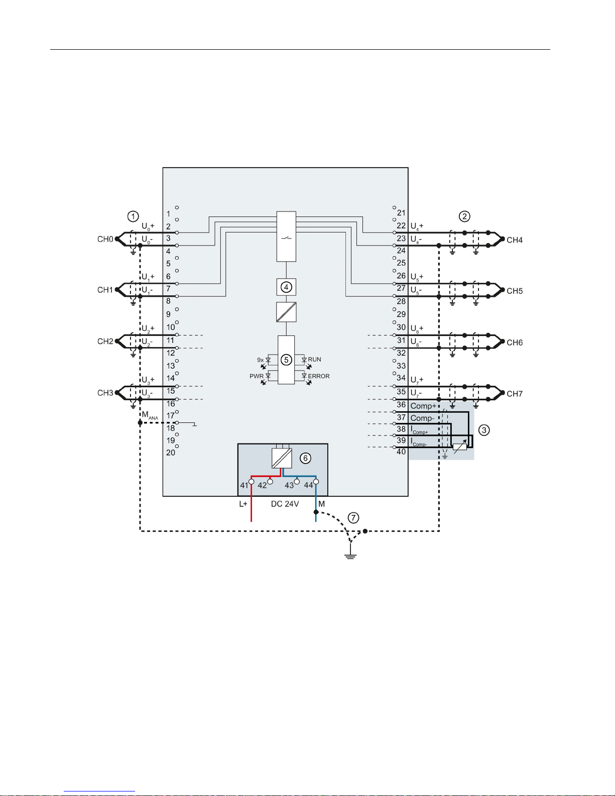
Connection: Non-grounded thermocouples for external/internal compensation and connection of a
resistance thermometer (RTD) at the reference channel
The following figure shows an example of the pin assignment of non-grounded
thermocouples for external/internal compensation and the connection of a resistance
thermometer (RTD) at the reference channel.
①
Wiring of a thermocouple (non-grounded) for internal
compensation
CHx Channel or 9 x channel status (green/red)
②
Wiring of a thermocouple (non-grounded) for external
compensation
RUN Status display LED (green)
③
Wiring of a resistance thermometer (RTD) at the
reference channel
ERROR Error display LED (red)
④
Analog-to-digital converter (ADC)
PWR
LED for power supply (green)
⑤
Backplane bus interface
⑥
Supply voltage via power supply element
⑦
Equipotential bonding cable (optional)
Figure 3-6 Block diagram and pin assignment for non-grounded thermocouples and resistance thermometers
Wiring
Analog input module AI 8xU/I/RTD/TC ST (6ES7531-7KF00-0AB0)
Manual, 09/2016, A5E03484864-AD
21
Connection: Grounded thermocouples for internal compensation
The following figure shows an example of the pin assignment for grounded thermocouples
for internal compensation.
①
Wiring of a thermocouple (grounded) for internal compen-
sation
CHx Channel or 9 x channel status (green/red)
②
Analog-to-digital converter (ADC)
RUN
Status display LED (green)
③
Backplane bus interface
ERROR
Error display LED (red)
④
Supply voltage via power supply element
PWR
LED for power supply (green)
⑤
Equipotential bonding cable (optional)
Figure 3-7 Block diagram and pin assignment for grounded thermocouples

Analog input module AI 8xU/I/RTD/TC ST (6ES7531-7KF00-0AB0)
22 Manual, 09/2016, A5E03484864-AD
4
4.1
Measuring types and ranges
Introduction
The module is set to voltage measurement type with measuring range ±10 V by default. You
need to reassign the module parameters with STEP 7 if you want to use a different
measurement type or range.
Deactivate the input if it is not going to be used. The module cycle time is shortened and the
interference factors that lead to failure of the module (for example, triggering a hardware
interrupt) are avoided.
The following table shows the measurement types and the respective measuring range.
Table 4- 1 Measurement types and measuring ranges
Measurement type
Measuring range
Representation of analog values
Voltage ±50 mV
±80 mV
±250 mV
±500 mV
±1 V
±2.5 V
1 V to 5 V
±5 V
±10 V
See Representation of analog values
in voltage measuring ranges (Page 66)
Current 2WMT
(2-wire transmitter)
4 mA to 20 mA See Representation of analog values
in the current measuring ranges
(Page 67)
Current 4WMT
(4-wire transmitter)
0 mA to 20 mA
4 mA to 20 mA
±20 mA
Resistor
(2-wire connection)
PTC
See Representation of the analog
values of resistance-based sensors/resistance thermometers
(Page 68)
Resistor
(3-wire connection)
(4-wire connection)
150 Ω
300 Ω
600 Ω
6000 Ω
Parameters/address space
4.1 Measuring types and ranges
Analog input module AI 8xU/I/RTD/TC ST (6ES7531-7KF00-0AB0)
Manual, 09/2016, A5E03484864-AD
23
Measurement type
Measuring range
Representation of analog values
Thermal resistor RTD
(3-wire connection)
(4-wire connection)
PT100 Standard/Climate
PT200 Standard/Climate
PT500 Standard/Climate
PT1000 Standard/Climate
Ni100 Standard/Climate
Ni1000 Standard/Climate
LG-Ni1000 Standard/Climatic
Thermocouple (TC) Type B
Type E
Type J
Type K
Type N
Type R
Type S
Type T
See Representation of analog values
for thermocouples (Page 71)
Disabled
-
-
The tables of the input ranges, overflow, underrange, etc. are available in the appendix
Representation of analog values (Page 64).
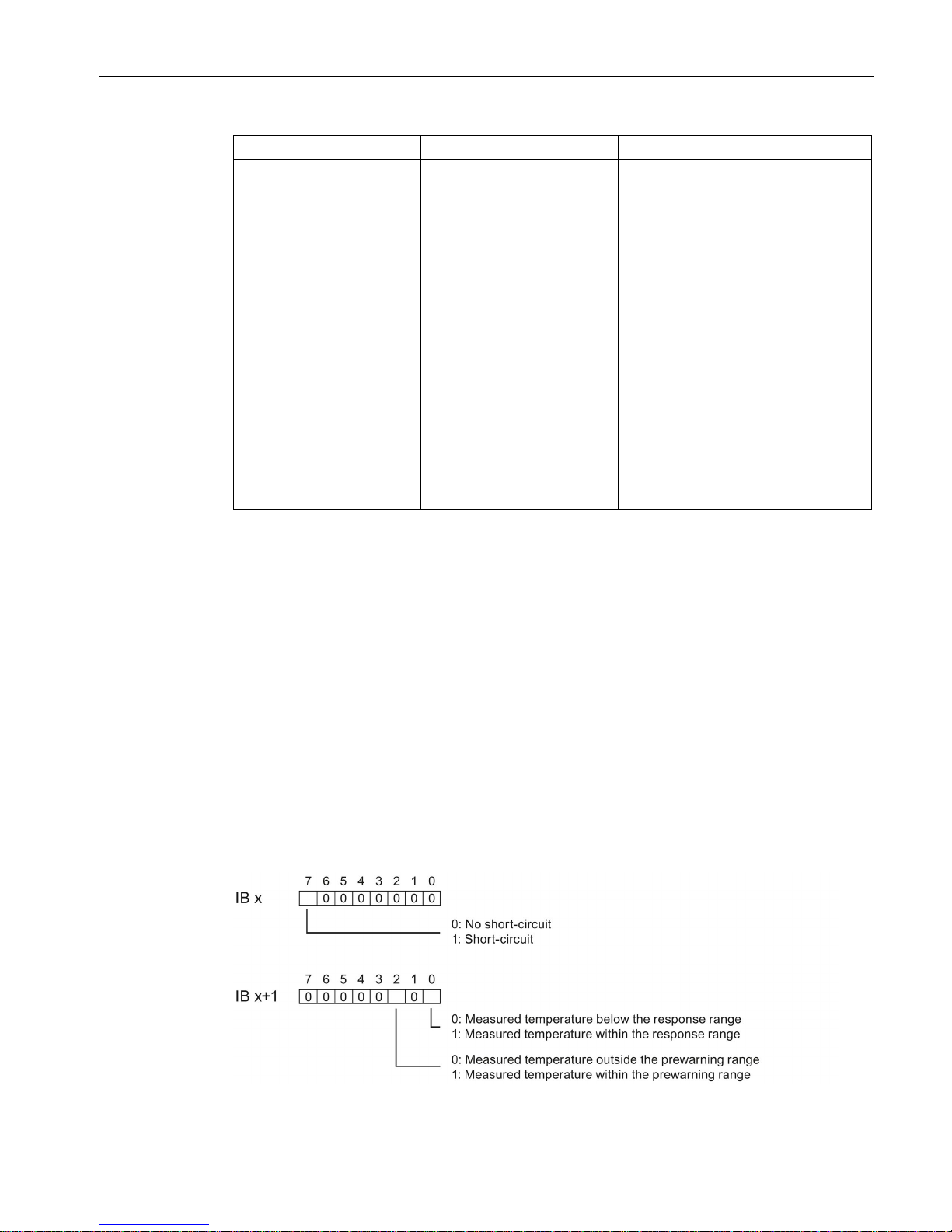
Using PTC resistors
PTC resistors are suitable for temperature monitoring of electrical devices, such as motors,
drives, and transformers.
Use Type A PTC resistors (PTC thermistor) in accordance with DIN/VDE 0660, part 302. In
doing so, follow these steps:
1. Choose "Resistor (2-wire terminal)" and "PTC" in STEP 7.
2. Connect the PTC using 2-wire connection technology.
If you enable the "Underflow" diagnostics in STEP 7, it will be signaled for resistance values
<18 Ω. In this case, this diagnostic signifies "Short-circuit in the wiring".
The following figure shows the address space assignment for the AI 8xU/I/RTD/TC ST
module with PTC resistors.
Figure 4-1 Address space for the AI 8xU/I/RTD/TC ST module with PTC resistors
 Loading...