

Siemens Simatic S7-1500, Simatic S7-1500H, Simatic ET 200pro, Simatic S7-1500R, Simatic ET 200SP Function Manual

___________________
___________________
___________________
___________________
___________________
___________
SIMATIC
S7-1500, S7-1500R/H, ET 200SP,
ET 200pro
Cycle and response times
Function Manual
10/2018
A5E03461504
-AD
Preface
Documentation guide
1
Program execution
2
Cyclic program execution
3
Event-driven program
execution
4
Cycle and response times of
the S7-1500R/H redundant
system
5
Siemens AG
Division Digital Factory
Postfach 48 48
90026 NÜRNBERG
GERMANY
A5E03461504-AD
Ⓟ
09/2018 Subject to change
Copyright © Siemens AG 2013 - 2018.
All rights reserved
Legal information
Warning notice system
This manual contains notices you have to observe in order to ensure your personal safety, as well as to prevent
damage to property. The notices referring to your personal safety are highlighted in the manual by a safety alert
symbol, notices referring only to property damage have no safety alert symbol. These notices shown below are
graded according to the degree of danger.
DANGER
indicates that death or severe personal injury will result if proper precautions are not taken.
WARNING
indicates that death or severe personal injury may result if proper precautions are not taken.
CAUTION
indicates that minor personal injury can result if proper precautions are not taken.
NOTICE
indicates that property damage can result if proper precautions are not taken.
If more than one degree of danger is present, the warning notice representing the highest degree of danger will
be used. A notice warning of injury to persons with a safety alert symbol may also include a warning relating to
property damage.
Qualified Personnel
The product/system described in this documentation may be operated only by
personnel qualified
for the specific
task in accordance with the relevant documentation, in particular its warning notices and safety instructions.
Qualified personnel are those who, based on their training and experience, are capable of identifying risks and
avoiding potential hazards when working with these products/systems.
Proper use of Siemens products
Note the following:
WARNING
Siemens products may only be used for the applications described in the catalog and in the relevant technical
documentation. If products and components from other manufacturers are used, these must be recommended
or approved by Siemens. Proper transport, storage, installation, assembly, commissioning, operation and
maintenance are required to ensure that the products operate safely and without any problems. The permissible
ambient conditions must be complied with. The information in the relevant documentation must be observed.
Trademarks
All names identified by ® are registered trademarks of Siemens AG. The remaining trademarks in this publication
may be trademarks whose use by third parties for their own purposes could violate the rights of the owner.
Disclaimer of Liability
We have reviewed the contents of this publication to ensure consistency with the hardware and software
described. Since variance cannot be precluded entirely, we cannot guarantee full consistency. However, the
information in this publication is reviewed regularly and any necessary corrections are included in subsequent
editions.

Cycle and response times
Function Manual, 10/2018, A5E03461504-AD
3
Preface
Purpose of the documentation
The controller offers various options for program execution with different run priorities.
Cyclic-driven and time-driven program execution have the largest share. The response times
of a controller are therefore significantly determined by the processing cycles.
There is also the possibility of event-driven program execution. The event-driven program
execution is normally limited to a few selected events.
This manual provides information on the following topics:
● Types of program execution
● Run priorities
● Cycle and response times, and the influences to which they are subject
● Configuration options for the optimization of your user program
Basic knowledge required
The following knowledge is required in order to understand the documentation:
● General knowledge of automation technology
● Knowledge of the SIMATIC industrial automation system
● Knowledge of the use of Windows-based computers
● Knowledge of working with STEP 7
Conventions
STEP 7: In this documentation, "STEP 7" is used as a synonym for all versions of the
configuration and programming software "STEP 7 (TIA Portal)".
Please also observe notes marked as follows:
Note
A note contains important information on the product described in the documentation, on the
handling of the product or on the section of the documentation to which particular attention
should be paid.

Preface
Cycle and response times
4 Function Manual, 10/2018, A5E03461504-AD
Scope of the documentation
This documentation mainly covers the description of the CPU components of the cycle and
response times of the following systems:
● S7-1500 automation system
● S7-1500R/H redundant system
● ET 200SP distributed I/O system
● CPU 1516pro-2 PN of the ET 200pro distributed I/O system
You can find links to more information on the ET 200MP, ET 200SP and ET 200pro
distributed I/O systems at the corresponding points in this manual.
What's new in edition 10/2018 as compared to edition 09/2016?
What's new?
What are the customer benefits?
Where can I find information?
Changed
contents
Scope of the function manual expanded to include
CPUs of the S7-1500R/H
redundant system
The determination of the cycle and response times of the S7-1500R/H redundant system follows the same principle as
for the CPUs of the S7-1500 automation
system.
Section Cycle and response
times of the S7-1500R/H redundant system (Page 51)
What's new in the 09/2016 edition compared to the 02/2014 edition?
What's new?
What are the customer benefits?
Where can I find information?
Changed
contents
Scope of the function manual expanded to include the
CPUs of the ET 200SP
distributed I/O system and
CPU 1516pro-2 PN of the
ET 200pro distributed I/O
system
Functions that you will be familiar with
from the SIMATIC S7-1500 CPUs are
implemented in CPUs in other designs
(ET 200SP) and in the CPU 1516pro-2 PN
(degree of protection IP 65, IP 66 and
IP 67)
.
Starting from section Program
execution (Page 13)
Recycling and disposal
For environmentally friendly recycling and disposal of your old equipment, contact a certified
electronic waste disposal company and dispose of the equipment according to the applicable
regulations in your country.

Preface
Cycle and response times
Function Manual, 10/2018, A5E03461504-AD
5
Security information
Siemens provides products and solutions with industrial security functions that support the
secure operation of plants, systems, machines and networks.
In order to protect plants, systems, machines and networks against cyber threats, it is
necessary to implement – and continuously maintain – a holistic, state-of-the-art industrial
security concept. Siemens' products and solutions constitute one element of such a concept.
Customers are responsible for preventing unauthorized access to their plants, systems,
machines and networks. Such systems, machines and components should only be
connected to an enterprise network or the internet if and to the extent such a connection is
necessary and only when appropriate security measures (e.g. firewalls and/or network
segmentation) are in place.
For additional information on industrial security measures that may be implemented, please
visit (https://www.siemens.com/industrialsecurity).
Siemens' products and solutions undergo continuous development to make them more
secure. Siemens strongly recommends that product updates are applied as soon as they are
available and that the latest product versions are used. Use of product versions that are no
longer supported, and failure to apply the latest updates may increase customers' exposure
to cyber threats.
To stay informed about product updates, subscribe to the Siemens Industrial Security RSS
Feed under (https://www.siemens.com/industrialsecurity).
Siemens Industry Online Support
You can find current information on the following topics quickly and easily here:
●
Product support
All the information and extensive know-how on your product, technical specifications,
FAQs, certificates, downloads, and manuals.
●
Application examples
Tools and examples to solve your automation tasks – as well as function blocks,
performance information and videos.
●
Services
Information about Industry Services, Field Services, Technical Support, spare parts and
training offers.
●
Forums
For answers and solutions concerning automation technology.
●
mySupport
Your personal working area in Industry Online Support for messages, support queries,
and configurable documents.
This information is provided by the Siemens Industry Online Support in the Internet
(https://support.industry.siemens.com).

Preface
Cycle and response times
6 Function Manual, 10/2018, A5E03461504-AD
Industry Mall
The Industry Mall is the catalog and order system of Siemens AG for automation and drive
solutions on the basis of Totally Integrated Automation (TIA) and Totally Integrated Power
(TIP).
You can find catalogs for all automation and drive products on the Internet
(https://mall.industry.siemens.com).

Cycle and response times
Function Manual, 10/2018, A5E03461504-AD
7
Table of contents
Preface ................................................................................................................................................... 3
1 Documentation guide .............................................................................................................................. 8
2 Program execution ................................................................................................................................ 13
2.1 Principle of operation .............................................................................................................. 13
2.2 Overload behavior ................................................................................................................... 16
3 Cyclic program execution ...................................................................................................................... 20
3.1 Cycle ....................................................................................................................................... 21
3.2 Cycle time ............................................................................................................................... 24
3.2.1 Different cycle times ................................................................................................................ 24
3.2.2 Influences on the cycle time ................................................................................................... 28
3.2.2.1 Update time for process image partitions ............................................................................... 28
3.2.2.2 User program execution time .................................................................................................. 31
3.2.2.3 Extension of cycle time due to communication load ............................................................... 36
3.2.2.4 Special consideration when PROFINET IO communication is configured on the 2nd
PROFINET interface (X2) ....................................................................................................... 38
3.3 Time-driven program execution in cyclic interrupts ................................................................ 40
3.4 Response time for cyclic and time-driven program execution ................................................ 42
3.5 Summary of response time with cyclic and time-controlled program execution ..................... 45
4 Event-driven program execution ............................................................................................................ 47
4.1 Response time of the CPUs when program execution is event-controlled ............................ 47
4.2 Process response time when program execution is event-driven .......................................... 49
5 Cycle and response times of the S7-1500R/H redundant system ........................................................... 51
5.1 Introduction ............................................................................................................................. 51
5.2 Maximum cycle time and time errors ...................................................................................... 52
5.3 Influences on the cycle time of the S7-1500R/H redundant system ....................................... 54
5.3.1 Influences on the cycle time in RUN-Solo system state ......................................................... 54
5.3.2 Influences on the cycle time in SYNCUP system state .......................................................... 55
5.3.3 Influences on the cycle time in RUN-Redundant system state............................................... 59
5.3.4 Influences on the cycle time when a CPU fails ....................................................................... 63
5.4 Response time of R/H CPUs .................................................................................................. 66
5.5 Timetables for the RUN-Redundant system state .................................................................. 69
Glossary ............................................................................................................................................... 72
Index..................................................................................................................................................... 77
Cycle and response times
8 Function Manual, 10/2018, A5E03461504-AD
1
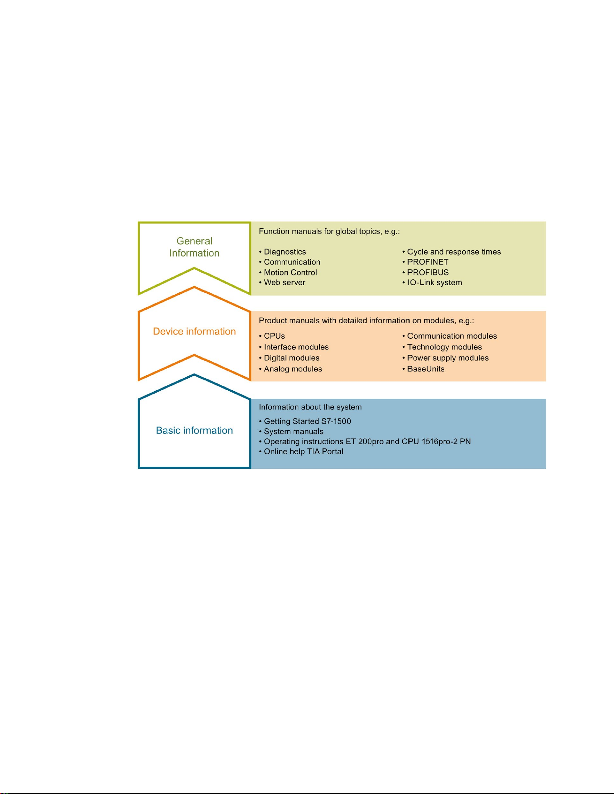
The documentation for the SIMATIC S7-1500 automation system, for CPU 1516pro-2 PN
based on SIMATIC S7-1500, and for the distributed I/O systems SIMATIC ET 200MP,
ET 200SP and ET 200AL is divided into three areas.
This division allows you easier access to the specific information you require.
Basic information
System manuals and Getting Started manuals describe in detail the configuration,
installation, wiring and commissioning of the SIMATIC S7-1500, ET 200MP, ET 200SP and
ET 200AL systems; use the corresponding operating instructions for CPU 1516pro-2 PN.
The STEP 7 online help supports you in configuration and programming.
Device information
Product manuals contain a compact description of the module-specific information, such as
properties, terminal diagrams, characteristics and technical specifications.

Documentation guide
Cycle and response times
Function Manual, 10/2018, A5E03461504-AD
9
General information
The function manuals contain detailed descriptions on general topics such as diagnostics,
communication, Motion Control, Web server, OPC UA.
You can download the documentation free of charge from the Internet
(https://support.industry.siemens.com/cs/ww/en/view/109742705).
Changes and additions to the manuals are documented in product information sheets.
You will find the product information on the Internet:
● S7-1500/ET 200MP (https://support.industry.siemens.com/cs/us/en/view/68052815)
● ET 200SP (https://support.industry.siemens.com/cs/us/en/view/73021864)
● ET 200AL (https://support.industry.siemens.com/cs/us/en/view/99494757)
Manual Collections
The Manual Collections contain the complete documentation of the systems put together in
one file.
You will find the Manual Collections on the Internet:
● S7-1500/ET 200MP (https://support.industry.siemens.com/cs/ww/en/view/86140384)
● ET 200SP (https://support.industry.siemens.com/cs/ww/en/view/84133942)
● ET 200AL (https://support.industry.siemens.com/cs/ww/en/view/95242965)
"mySupport"
With "mySupport", your personal workspace, you make the best out of your Industry Online
Support.
In "mySupport", you can save filters, favorites and tags, request CAx data and compile your
personal library in the Documentation area. In addition, your data is already filled out in
support requests and you can get an overview of your current requests at any time.
You must register once to use the full functionality of "mySupport".
You can find "mySupport" on the Internet (https://support.industry.siemens.com/My/ww/en).
"mySupport" - Documentation
In the Documentation area in "mySupport" you can combine entire manuals or only parts of
these to your own manual.
You can export the manual as PDF file or in a format that can be edited later.
You can find "mySupport" - Documentation on the Internet
(https://support.industry.siemens.com/My/ww/en/documentation).

Documentation guide
Cycle and response times
10 Function Manual, 10/2018, A5E03461504-AD
"mySupport" - CAx data
In the CAx data area in "mySupport", you can access the current product data for your CAx
or CAe system.
You configure your own download package with a few clicks.
In doing so you can select:
● Product images, 2D dimension drawings, 3D models, internal circuit diagrams, EPLAN
macro files
● Manuals, characteristics, operating manuals, certificates
● Product master data
You can find "mySupport" - CAx data on the Internet
(https://support.industry.siemens.com/my/ww/en/CAxOnline).
Application examples
The application examples support you with various tools and examples for solving your
automation tasks. Solutions are shown in interplay with multiple components in the system separated from the focus on individual products.
You will find the application examples on the Internet
(https://support.industry.siemens.com/sc/ww/en/sc/2054).
TIA Selection Tool
With the TIA Selection Tool, you can select, configure and order devices for Totally
Integrated Automation (TIA).
This tool is the successor of the SIMATIC Selection Tool and combines the known
configurators for automation technology into one tool.
With the TIA Selection Tool, you can generate a complete order list from your product
selection or product configuration.
You can find the TIA Selection Tool on the Internet
(https://w3.siemens.com/mcms/topics/en/simatic/tia-selection-tool).

Documentation guide
Cycle and response times
Function Manual, 10/2018, A5E03461504-AD
11
SIMATIC Automation Tool
You can use the SIMATIC Automation Tool to run commissioning and maintenance activities
simultaneously on different SIMATIC S7 stations as a bulk operation, independently of the
TIA Portal.
The SIMATIC automation tool provides a variety of functions:
● Scanning of a PROFINET/Ethernet plant network and identification of all connected CPUs
● Address assignment (IP, subnet, gateway) and station name (PROFINET device) to a
CPU
● Transfer of the date and programming device/PC time converted to UTC time to the
module
● Program download to CPU
● Operating mode switchover RUN/STOP
● CPU localization by means of LED flashing
● Reading out CPU error information
● Reading of CPU diagnostic buffer
● Reset to factory settings
● Updating the firmware of the CPU and connected modules
You can find the SIMATIC Automation Tool on the Internet
(https://support.industry.siemens.com/cs/ww/en/view/98161300).
PRONETA
With SIEMENS PRONETA (PROFINET network analysis), you analyze the plant network
during commissioning. PRONETA features two core functions:
● The topology overview independently scans PROFINET and all connected components.
● The IO check is a fast test of the wiring and the module configuration of a plant.
You can find SIEMENS PRONETA on the Internet
(https://support.industry.siemens.com/cs/ww/en/view/67460624).

Documentation guide
Cycle and response times
12 Function Manual, 10/2018, A5E03461504-AD
SINETPLAN
SINETPLAN, the Siemens Network Planner, supports you in planning automation systems
and networks based on PROFINET. The tool facilitates professional and predictive
dimensioning of your PROFINET installation as early as in the planning stage. In addition,
SINETPLAN supports you during network optimization and helps you to exploit network
resources optimally and to plan reserves. This helps to prevent problems in commissioning
or failures during productive operation even in advance of a planned operation. This
increases the availability of the production plant and helps improve operational safety.
The advantages at a glance
● Network optimization thanks to port-specific calculation of the network load
● Increased production availability thanks to online scan and verification of existing systems
● Transparency before commissioning through importing and simulation of existing STEP 7
projects
● Efficiency through securing existing investments in the long term and optimal exploitation
of resources
You can find SINETPLAN on the Internet (https://www.siemens.com/sinetplan).

Cycle and response times
Function Manual, 10/2018, A5E03461504-AD
13
2
2.1
Principle of operation
Introduction
You often program your user program with a cyclic OB, usually in OB 1. With complex
applications, problems are often encountered in complying with the response times required
by the application. You can often meet the response time requirements by splitting the user
program up into several parts with different response time requirements. The CPU offers a
number of different OB types for this purpose, the properties (priority, frequency, etc.) of
which can be adapted to meet your requirements.
Program organization
You can choose from the following types of program execution for running your user
program:
Program execution in the cyclic program of the CPU:
The CPU executes the user program cyclically. When the execution has reached the end of
a cycle, the program execution starts again in the next cycle. In the simplest case, you
execute the entire user program in the cyclic program of the CPU. All tasks in the user
program are then processed with equal rank. This also results in the same response times
for all tasks.
In addition to program execution in the cyclic program, there is time-driven and event-driven
program execution.
Time-driven execution:
In a complex user program, there are frequently portions with different response time
requirements. You can optimize the response times by taking advantage of these differences
in the requirements. To do so, you can break down the program parts with higher response
time requirements into higher-priority OBs with shorter cycles, for example cyclic interrupt
OBs.
The execution of these parts can thus occur at different frequencies and with different
priorities.
Event-driven execution:
Depending on the I/O modules used, you can configure hardware interrupts for specific
process events (such as an edge change of a digital input) that result in the call of the
assigned hardware interrupt OB. The hardware interrupts have a higher priority and interrupt
the cyclic program of the CPU. You can achieve very short response times in the CPU with
hardware interrupts by directly triggering program execution.
Keep in mind that the time characteristics of your application becomes less predictable with
intense use of hardware interrupts. The reason for this is that the time at which the triggering
events occur can result in drastically different response times.
Tip:
Use hardware interrupts only for a few selected events.
Special consideration for hardware interrupts:
If you have assigned an OB to an event
(hardware interrupt), the OB then has the priority of the event.

Program execution
2.1 Principle of operation
Cycle and response times
14 Function Manual, 10/2018, A5E03461504-AD
Using process image partitions
If you have distributed a program over various OBs, for example, due to different response
time requirements, it is advisable and often necessary to assign the update of the used I/O
data directly to these OBs. You can use process image partitions for this purpose.
You group the input and output data in a process image partition according to their use in the
program and assign the data to the OB.
A process image partition of the inputs (PIPI) permits the associated input data for an OB
program to be updated immediately before the OB program starts.
A process image partition of the outputs (PIPQ) permits the output data associated with an
OB program to become effective on the outputs immediately after the OB program runs.
You have 32 (0 … 31) process image partitions at your disposal. The I/O is assigned to the
process image partition 0 by default (setting: "Automatic update"). Process image partition 0
is permanently assigned to cyclic execution.
You have to configure the "system-side update of process image partitions". You can find
additional information on configuration of process image partitions in the online help for
STEP 7 under the keyword "Assign process image/process image partition".
Interruptibility of program execution
Each organization block is processed according to the priority it has been assigned. You can
adapt the priority according to the response time requirements for most organization blocks.
All cycle OBs always have the lowest priority of 1. The highest priority is 26.
Communication tasks always have priority 15. If necessary, you can change the priority of
your blocks and select a higher priority than the communication.
Organization blocks or system activities with higher priority interrupt organization blocks or
system activities with lower priority. Organization blocks or system activities with higher
priority interrupt thus extend the runtime of the interrupted organization blocks or system
activities. If two pending tasks have the same priority, these tasks are processed in the order
in which the tasks occurred.
Note
Higher priority OBs
Communication functionality is strongly influenced by too many and/
or runtime-
intensive OBs
with a priority
> 15.
When using OBs with a priority
> 15, you should therefore consider the runtime load that
they cause.

Program execution
2.1 Principle of operation
Cycle and response times
Function Manual, 10/2018, A5E03461504-AD
15
Reference
You can find additional information on the subject of "priorities" in the "Events and OBs"
section of the following manuals:
● S7-1500 automation system
(https://support.industry.siemens.com/cs/ww/en/view/59191792) system manual
● S7-1500R/H redundant system
(https://support.industry.siemens.com/cs/ww/en/view/109754833) system manual
● ET 200SP distributed I/O system
(https://support.industry.siemens.com/cs/ww/en/view/58649293) system manual
● CPU 1516pro-2 PN (https://support.industry.siemens.com/cs/ww/en/view/109482416)
operating instructions
You can find additional information on organization blocks and their priorities for Motion
Control in the S7-1500T Motion Control
(https://support.industry.siemens.com/cs/ww/en/view/109481326) function manual.
Program execution
2.2 Overload behavior
Cycle and response times
16 Function Manual, 10/2018, A5E03461504-AD
2.2
Overload behavior
CPU overload behavior
An occurring event triggers the execution of the associated OB. Depending on the OB
priority and the current processor load, a time delay may occur before the OB is executed
when there is an overload. The same event can therefore occur once or several times before
the user program processes the OB belonging to the preceding event. The CPU handles
such a situation as follows: The operating system queues the events in the queue associated
with their priority in the order of their occurrence. The CPU then takes the oldest event for
the highest priority and processes the associated OB. After the OB has been processed, the
CPU processes the OB for the next event.
To control temporary overload situations, you can limit the number of queued events that
originate from the same source. The next event is discarded as soon as the maximum
number of pending triggers of a specific cyclic interrupt OB, for example, is reached.
Overload occurs when similar events occur faster than the CPU can process these events.
Similar events are events from a single source, such as start events for a specific cyclic
interrupt OB.
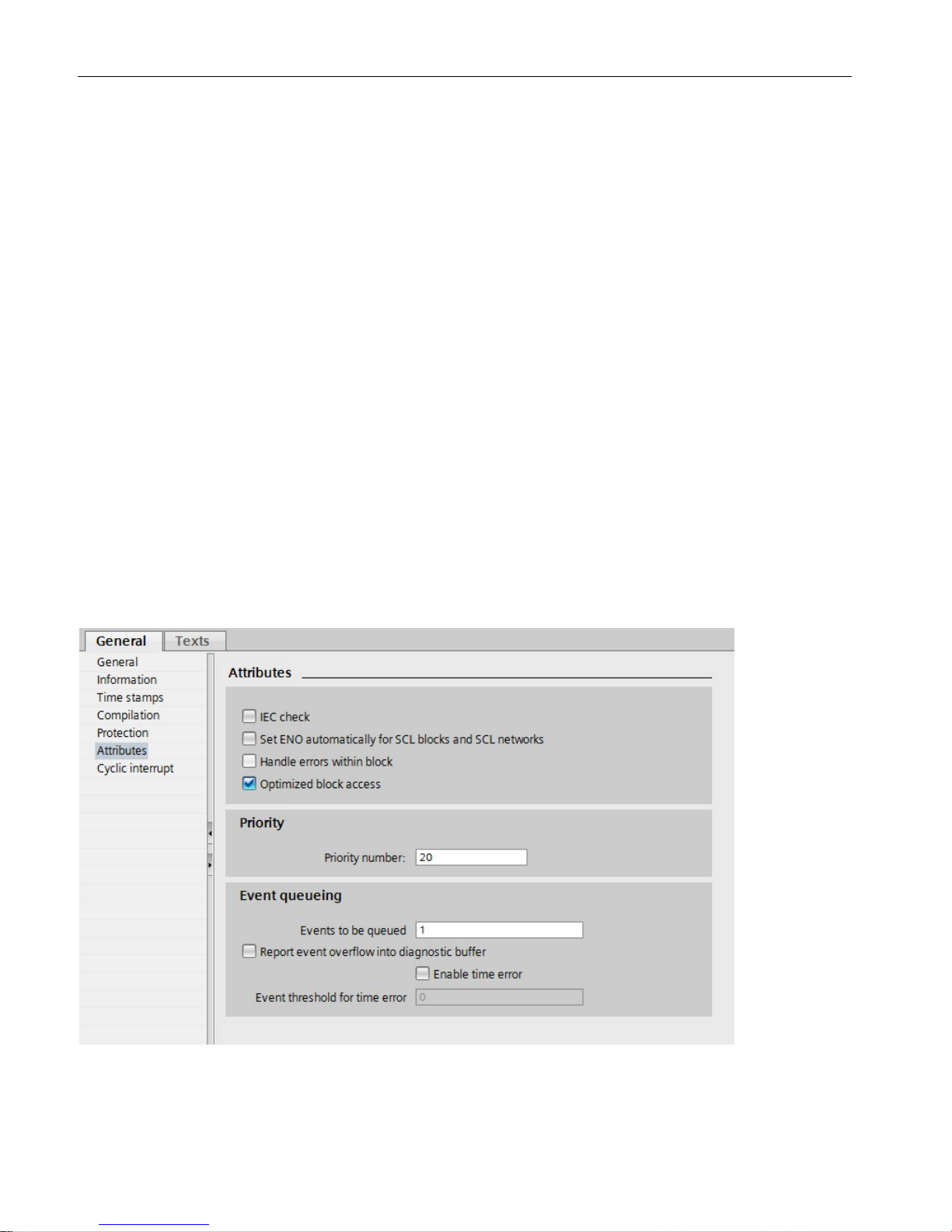
Configuration of the overload response
In the properties of an organization block in which an overload can occur, you can select the
response to the overload response under "Attributes" and "Event queuing".
Figure 2-1 Configuration of the overload response in the block properties

Program execution
2.2 Overload behavior
Cycle and response times
Function Manual, 10/2018, A5E03461504-AD
17
Events to be queued
The OB parameter "Events to be queued" is used to specify how many similar events the
operating system places in the associated queue and therefore post-processes. If this
parameter has the value 1, for example, exactly one event is stored temporarily.
If the maximum number of similar start events is reached in the queue, each additional start
event is only counted and subsequently discarded. During the next scheduled processing of
the event, the CPU provides the number of discarded start events in the "Event_Count" input
parameter (in the start information). You can then react appropriately to the overload
situation. The CPU then resets the counter for lost events to zero.
Note
Post
-processing of cyclic events is often not desirable, as this can lead to an overload with
OBs of the same or lower priorit
y. Therefore, it is generally advantageous to discard similar
events and to react to the overload situation during the next scheduled OB processing. A low
value of the "Events to be queued" parameter mitigates an overload situation.
To ensure that the CPU
processes the OB of at least one queued event, the minimum
number of events to be queued is "1". The maximum number of events that can be queued
is "12".
Report event overflow into diagnostic buffer
If the CPU first discards a start event of a cyclic interrupt OB, for example, its further
behavior depends on the OB parameter "Report event overflow into diagnostic buffer". If you
have selected the check box, the CPU enters the event DW#16#0002:3507 in the diagnostic
buffer for the overload situation at this event source. If an overload situation occurs again
(overflow counter changes from 0 to 1), another diagnostic buffer entry is made at the next
OB end.
Enable time error
The cyclic interrupt OB parameter "Enable time error" is used to specify whether the CPU is
to call a time error OB when a specific overload level is reached for similar events. You use
the OB parameter "Enable time error" to program a reaction to an overload before the limit
for similar events is reached. The reaction occurs before the CPU discards similar events.
By default, the "Enable time error" parameter is not set.
Event threshold for time error
Select the "Enable time error" check box to enable the "Event threshold for time error" OB
parameter. You use the "Event threshold for time error" OB parameter to specify how many
similar events in the queue are permitted before the CPU calls a time error OB.
The following value range applies to the "Event threshold for time error" parameter:
1 ≤ "Event threshold for time error" ≤ "Events to be queued".
Program execution
2.2 Overload behavior
Cycle and response times
18 Function Manual, 10/2018, A5E03461504-AD
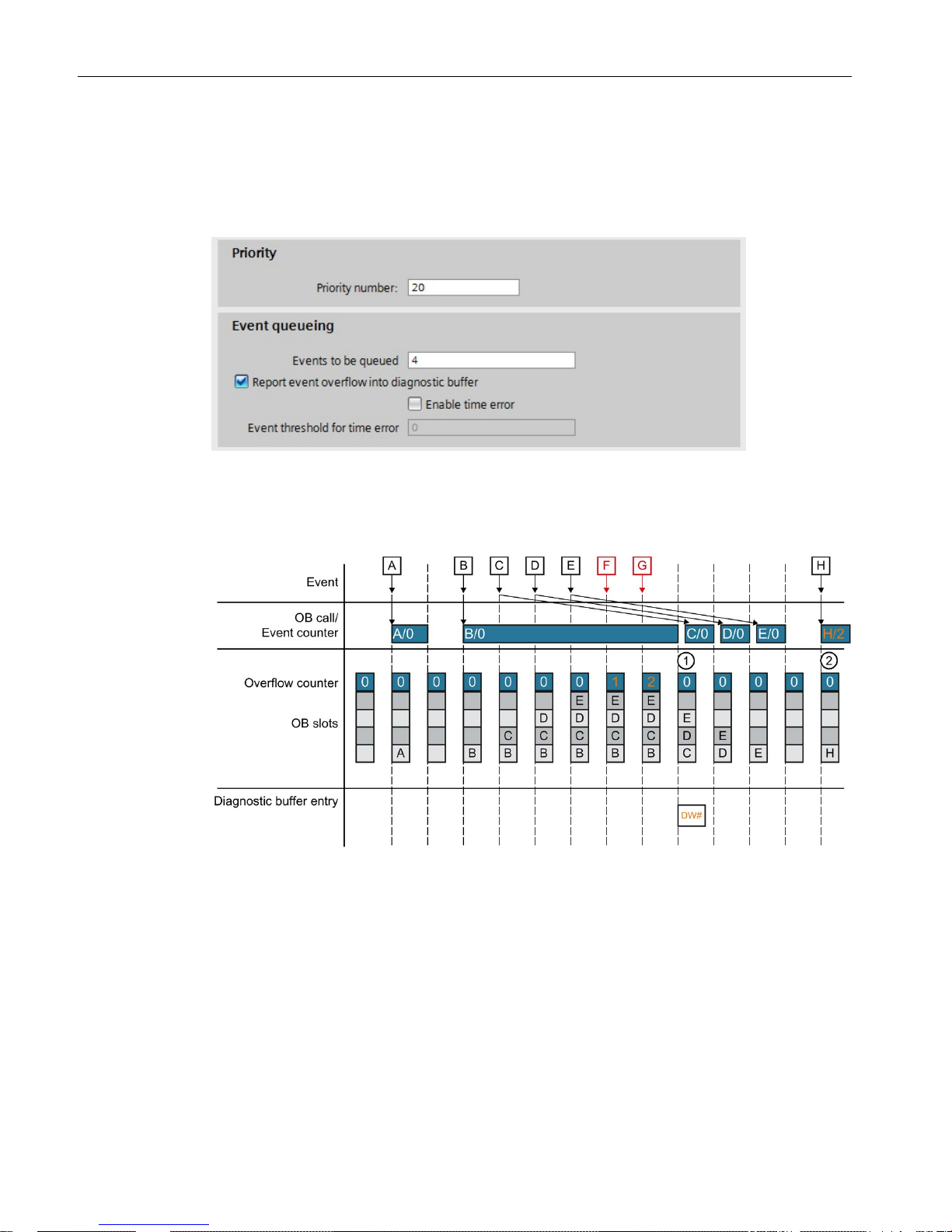
Example 1
The following example shows the response of the CPU when multiple similar events occur
faster than the CPU can process the associated OBs. In example 1, the user selected the
following parameter assignment:
Figure 2-2 Example of parameter assignment for the overload behavior
The figure below shows the processing sequence as soon as an event calls an associated
OB.
Figure 2-3 Example 1
As soon as an occurring event calls an OB, the event occupies a slot of the OB. The
occupied slot is free again as soon as the CPU has processed the event. If the CPU has not
completed processing the OB of an occurring event, additional occurring events each occupy
an additional slot of the OB during this time. As soon as this number exceeds the configured
number of events to be queued, these events are discarded and counted by the overflow
counter. When an OB which takes a long time to run is completed, the CPU creates an entry
in the diagnostic buffer and sets the overflow counter to zero (
①). After the CPU has
processed this long-running OP, the CPU then processes the OBs of the events that are
queued one after the other. At the next new occurring event, the CPU writes the previous
value of the reset overflow counter to the start information of the OB. The CPU then
processes the OB (
②).
Program execution
2.2 Overload behavior
Cycle and response times
Function Manual, 10/2018, A5E03461504-AD
19
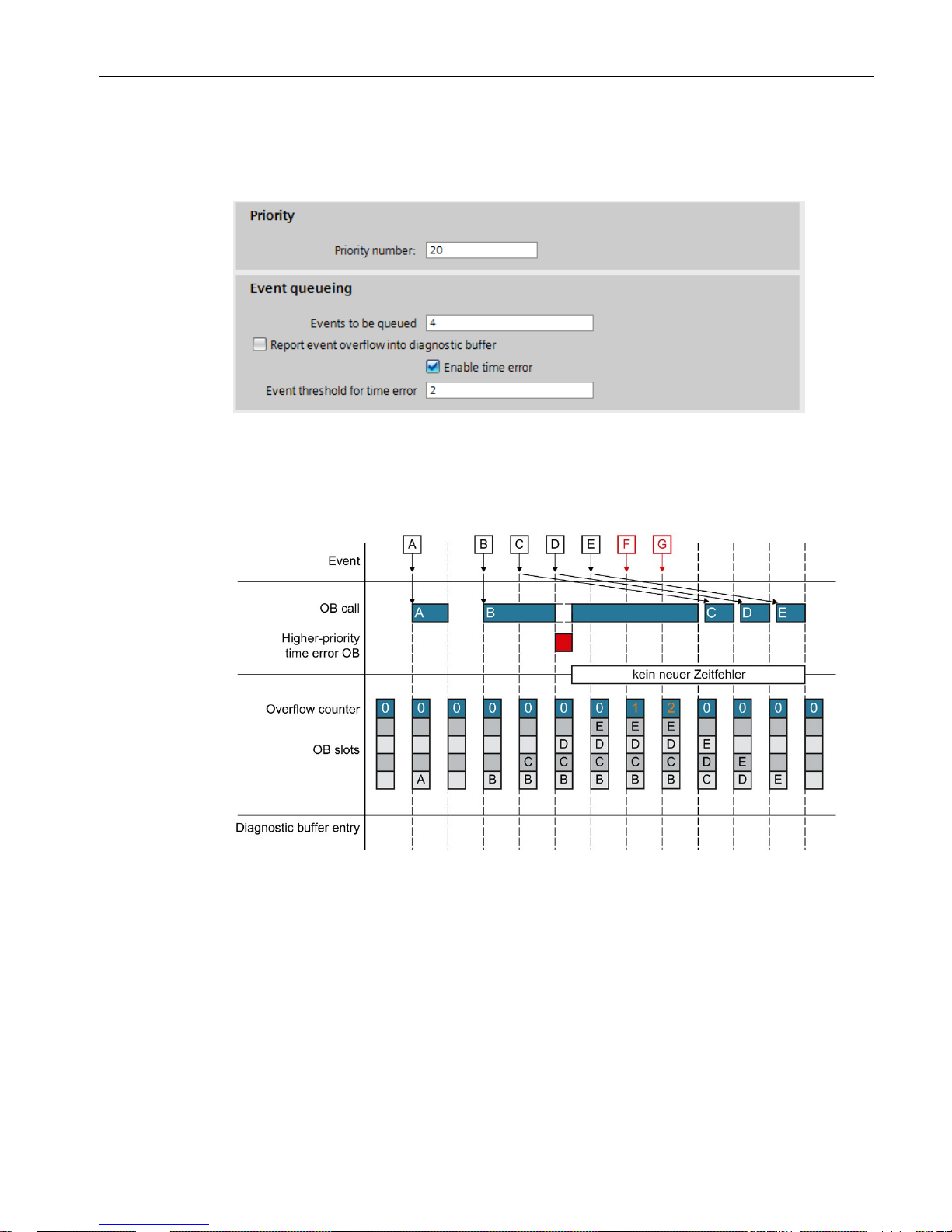
Example 2
In example 2, the user has selected the following parameter assignment:
Figure 2-4 Example of parameter assignment for the overload behavior
Contrary to example 1, the CPU in example 2 requests a time error as soon as the
configured event threshold has been exceeded. An additional time error can then only occur
if all slots of the OB have been free once in the meantime.
Figure 2-5 Example 2

Cycle and response times
20 Function Manual, 10/2018, A5E03461504-AD
3
Validity
The statements of the section "Cyclic program execution" apply to the CPU components of
the following systems:
● S7-1500 automation system
● ET 200MP and ET 200SP distributed I/O systems
● CPU 1516pro-2 PN of the ET 200pro distributed I/O system
● S7-1500R/H redundant system (in RUN-Solo system state)
In RUN-Redundant system state, the statements of section
"
Cycle and response times of
the S7-1500R/H redundant system (Page 51)" apply.
Restrictions
With the S7-1500R/H redundant system, there are restrictions compared to the S7-1500
automation system. The S7-1500R/H redundant system does not support all hardware
properties and firmware functions of the S7-1500 automation system (for example, it does
not support PROFIBUS DP, central I/O, web server, etc.).
The restrictions are described in the S7-1500R/H redundant system
(https://support.industry.siemens.com/cs/ww/en/view/109754833) system manual.
Cyclic program execution
3.1 Cycle
Cycle and response times
Function Manual, 10/2018, A5E03461504-AD
21
3.1
Cycle
Definition of cycle
A cycle includes the following sections:
● Update of process image partition 0 of the outputs (PIPQ 0)
● Automatic update of the process image partition 0 of the inputs (PIPI 0)
● Execution of the cyclic program
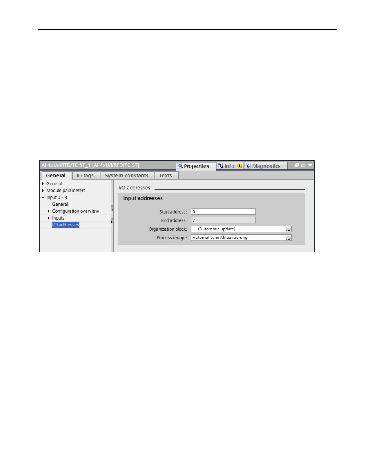
The process image partition 0 is automatically updated in the cycle. You assign the I/O
addresses to these process image partitions (PIPI 0/PIPQ 0) when you configure the I/O
modules via the "Automatic update" setting (default).
Figure 3-1 Assigning I/O addresses to process image partitions

Cyclic program execution
3.1 Cycle
Cycle and response times
22 Function Manual, 10/2018, A5E03461504-AD
The figure below illustrates the phases that are passed through during a cycle. In the
example below the user has configured a minimum cycle time. Updating of the process
image partitions and processing of the cyclic program is completed before the end of the
configured minimum cycle time. Therefore, the CPU waits until the configured minimum
cycle time has expired before the next program cycle starts.
①
The operating system starts measurement of the cycle time.
②
The CPU writes the states from the process image output to the output modules.
③
The CPU reads the status of the inputs at the input modules and writes the input data to the
process image input.
④
The CPU processes the user program and executes the instructions specified in the program.
⑤
The CPU updates the process image partitions and processes the cyclic program.
⑥
Wait phase until end of configured minimum cycle time
⑦
The operating system restarts the monitoring of the maximum cycle time, evaluates the calcu-
lated cycle time, and starts the new measurement.
Figure 3-2 Cycle

Cyclic program execution
3.1 Cycle
Cycle and response times
Function Manual, 10/2018, A5E03461504-AD
23
Cycle control point
When the cycle control point is reached, the CPU has completed the cycle program and is
no longer executing OBs. All user data are consistent at this time. Requirement is that no
communication that modifies user data (such as HMI communication or PUT/GET
communication) is active.
The cycle control point marks:
● The end of a cycle and its cycle time statistics
● The start of the next cycle and its cycle time statistics
● The restart of the monitoring of the configured maximum cycle time
(time-out counter is reset)
The cycle control point is reached depending on which of the following events occurred last:
● End of the last cyclic OB
● Expiry of the minimum cycle time (if configured)
After the cycle control point has been reached, the CPU executes the following steps:
1. Writes the process image outputs to the output modules
2. Reads the state of the inputs into the input modules
3. Executes the first cyclic OB
 Loading...