

Siemens Simatic S7-1500 / ET 200MP, Simatic S7-1500 User Manual

___________________
___________________
___________________
___________________
___________________
___________________
___________________
___________________
___________________
___________________
SIMATIC
S7-1500/ET 200MP
Analog Input Module AI 8xU/I HF
(6ES7531-7NF00-0AB0)
Manual
09/2016
A5E36649087
-AB
Preface
Documentation guide
1
Product overview
2
Wiring
3
Parameters/address space
4
Interrupts/diagnostics alarms
5
Technical specifications
6
Dimensional drawing
A
Parameter data records
B
Representation of analog
values
C
Siemens AG
Division Digital Factory
Postfach 48 48
90026 NÜRNBERG
GERMANY
A5E36649087-AB
Ⓟ
09/2016 Subject to change
Copyright © Siemens AG 2016.
All rights reserved
Legal information
Warning notice system
This manual contains notices you have to observe in order to ensure your personal safety, as well as to prevent
damage to property. The notices referring to your personal safety are highlighted in the manual by a safety alert
symbol, notices referring only to property damage have no safety alert symbol. These notices shown below are
graded according to the degree of danger.
DANGER
indicates that death or severe personal injury will result if proper precautions are not taken.
WARNING
indicates that death or severe personal injury may result if proper precautions are not taken.
CAUTION
indicates that minor personal injury can result if proper precautions are not taken.
NOTICE
indicates that property damage can result if proper precautions are not taken.
If more than one degree of danger is present, the warning notice representing the highest degree of danger will
be used. A notice warning of injury to persons with a safety alert symbol may also include a warning relating to
property damage.
Qualified Personnel
The product/system described in this documentation may be operated only by
personnel qualified
for the specific
task in accordance with the relevant documentation, in particular its warning notices and safety instructions.
Qualified personnel are those who, based on their training and experience, are capable of identifying risks and
avoiding potential hazards when working with these products/systems.
Proper use of Siemens products
Note the following:
WARNING
Siemens products may only be used for the applications described in the catalog and in the relevant technical
documentation. If products and components from other manufacturers are used, these must be recommended
or approved by Siemens. Proper transport, storage, installation, assembly, commissioning, operation and
maintenance are required to ensure that the products operate safely and without any problems. The permissible
ambient conditions must be complied with. The information in the relevant documentation must be observed.
Trademarks
All names identified by ® are registered trademarks of Siemens AG. The remaining trademarks in this publication
may be trademarks whose use by third parties for their own purposes could violate the rights of the owner.
Disclaimer of Liability
We have reviewed the contents of this publication to ensure consistency with the hardware and software
described. Since variance cannot be precluded entirely, we cannot guarantee full consistency. However, the
information in this publication is reviewed regularly and any necessary corrections are included in subsequent
editions.

Analog Input Module AI 8xU/I HF (6ES7531-7NF00-0AB0)
4 Manual, 09/2016, A5E36649087-AB
Preface
Purpose of the documentation
This manual supplements the S7-1500/ET 200MP
(http://support.automation.siemens.com/WW/view/en/59191792) system manual.
Functions that relate in general to the systems are described in these system manuals.
The information provided in this manual and in the system/function manuals supports you in
commissioning the systems.
Changes compared to previous version
Compared to the previous version, this manual contains the following changes:
● As of firmware version V1.1.0, the module supports the following functions:
– Measuring range adjustment
– Scaling of measured values
● Original texts of the license conditions and copyright notes for open-source software are
available on the Internet as of 09/2016.
Conventions
The term "CPU" is used in this manual both for the CPUs of the S7-1500 automation system,
as well as for interface modules of the ET 200MP distributed I/O system.
Please also observe notes marked as follows:
Note
A note contains important information regarding the product described in the documentation
or its handling, or draws special attention to a
section of the documentation.

Preface
Analog Input Module AI 8xU/I HF (6ES7531-7NF00-0AB0)
Manual, 09/2016, A5E36649087-AB
5
Security information
Siemens provides products and solutions with industrial security functions that support the
secure operation of plants, systems, machines and networks.
In order to protect plants, systems, machines and networks against cyber threats, it is
necessary to implement – and continuously maintain – a holistic, state-of-the-art industrial
security concept. Siemens’ products and solutions only form one element of such a concept.
Customer is responsible to prevent unauthorized access to its plants, systems, machines
and networks. Systems, machines and components should only be connected to the
enterprise network or the internet if and to the extent necessary and with appropriate security
measures (e.g. use of firewalls and network segmentation) in place.
Additionally, Siemens’ guidance on appropriate security measures should be taken into
account. For more information about industrial security, please visit
(http://www.siemens.com/industrialsecurity).
Siemens’ products and solutions undergo continuous development to make them more
secure. Siemens strongly recommends to apply product updates as soon as available and to
always use the latest product versions. Use of product versions that are no longer supported,
and failure to apply latest updates may increase customer’s exposure to cyber threats.
To stay informed about product updates, subscribe to the Siemens Industrial Security RSS
Feed under (http://www.siemens.com/industrialsecurity).
Open Source Software
Open-source software is used in the firmware of the I/O modules. Open Source Software is
provided free of charge. We are liable for the product described, including the open-source
software contained in it, pursuant to the conditions applicable to the product. Siemens
accepts no liability for the use of the open source software over and above the intended
program sequence, or for any faults caused by modifications to the software.
For legal reasons, we are obliged to publish the original text of the license conditions and
copyright notices. Please read the information relating to this on the Internet
(https://support.industry.siemens.com/cs/ww/en/view/109739516).

Analog Input Module AI 8xU/I HF (6ES7531-7NF00-0AB0)
6 Manual, 09/2016, A5E36649087-AB
Table of contents
Preface ................................................................................................................................................... 4
1 Documentation guide .............................................................................................................................. 7
2 Product overview .................................................................................................................................. 11
2.1 Properties ............................................................................................................................... 11
2.2 Functions ................................................................................................................................ 14
2.2.1 Measuring range adjustment ................................................................................................. 14
2.2.2 Scaling of measured values ................................................................................................... 17
3 Wiring ................................................................................................................................................... 21
4 Parameters/address space ................................................................................................................... 25
4.1 Measuring types and ranges .................................................................................................. 25
4.2 Parameters ............................................................................................................................. 26
4.3 Declaration of parameters ...................................................................................................... 29
4.4 Address space ....................................................................................................................... 32
5 Interrupts/diagnostics alarms................................................................................................................. 39
5.1 Status and error displays ....................................................................................................... 39
5.2 Interrupts ................................................................................................................................ 41
5.3 Diagnostics alarms ................................................................................................................. 43
6 Technical specifications ........................................................................................................................ 44
A Dimensional drawing ............................................................................................................................. 48
B Parameter data records ........................................................................................................................ 50
B.1 Parameter assignment ........................................................................................................... 50
B.2 Structure of the parameter data records without scaling of measured values ...................... 52
B.3 Structure of the parameter data records with scaling of measured values ........................... 55
B.4 Codes for measurement types/measuring ranges and limits for hardware interrupts ........... 58
C Representation of analog values ........................................................................................................... 60
C.1 Representation of input ranges .............................................................................................. 61
C.2 Representation of analog values in voltage measuring ranges ............................................. 62
C.3 Representation of analog values in the current measuring ranges ....................................... 63
C.4 Measured values for wire break diagnostic ........................................................................... 64
Analog Input Module AI 8xU/I HF (6ES7531-7NF00-0AB0)
Manual, 09/2016, A5E36649087-AB
7
1
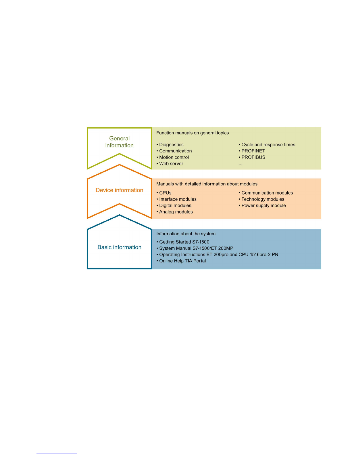
The documentation for the SIMATIC S7-1500 automation system, the CPU 1516pro-2 PN
based on SIMATIC S7-1500 and the SIMATIC ET 200MP distributed I/O system is arranged
into three areas.
This arrangement enables you to access the specific content you require.
Basic information
The System Manual and Getting Started describe in detail the configuration, installation,
wiring and commissioning of the SIMATIC S7-1500 and ET 200MP systems. For
CPU 1516pro-2 PN you use the corresponding operating instructions. The STEP 7 online
help supports you in the configuration and programming.
Device information
Product manuals contain a compact description of the module-specific information, such as
properties, wiring diagrams, characteristics and technical specifications.

Documentation guide
Analog Input Module AI 8xU/I HF (6ES7531-7NF00-0AB0)
8 Manual, 09/2016, A5E36649087-AB
General information
The function manuals contain detailed descriptions on general topics regarding the SIMATIC
S7-1500 and ET 200MP systems, e.g. diagnostics, communication, motion control, Web
server, OPC UA.
You can download the documentation free of charge from the Internet
(http://w3.siemens.com/mcms/industrial-automation-systems-simatic/en/manual-
overview/Pages/Default.aspx).
Changes and supplements to the manuals are documented in a Product Information.
You can download the product information free of charge from the Internet
(https://support.industry.siemens.com/cs/us/en/view/68052815).
Manual Collection S7-1500/ET 200MP
The Manual Collection contains the complete documentation on the SIMATIC S7-1500
automation system and the ET 200MP distributed I/O system gathered together in one file.
You can find the Manual Collection on the Internet
(https://support.industry.siemens.com/cs/ww/en/view/86140384).
SIMATIC S7-1500 comparison list for programming languages
The comparison list contains an overview of which instructions and functions you can use for
which controller families.
You can find the comparison list on the Internet
(https://support.industry.siemens.com/cs/ww/en/view/86630375).
"mySupport"
With "mySupport", your personal workspace, you make the best out of your Industry Online
Support.
In "mySupport", you can save filters, favorites and tags, request CAx data and compile your
personal library in the Documentation area. In addition, your data is already filled out in
support requests and you can get an overview of your current requests at any time.
You must register once to use the full functionality of "mySupport".
You can find "mySupport" on the Internet (https://support.industry.siemens.com/My/ww/en).
"mySupport" - Documentation
In the Documentation area in "mySupport" you can combine entire manuals or only parts of
these to your own manual.
You can export the manual as PDF file or in a format that can be edited later.
You can find "mySupport" - Documentation on the Internet
(http://support.industry.siemens.com/My/ww/en/documentation).

Documentation guide
Analog Input Module AI 8xU/I HF (6ES7531-7NF00-0AB0)
Manual, 09/2016, A5E36649087-AB
9
"mySupport" - CAx data
In the CAx data area in "mySupport", you can access the current product data for your CAx
or CAe system.
You configure your own download package with a few clicks.
In doing so you can select:
● Product images, 2D dimension drawings, 3D models, internal circuit diagrams, EPLAN
macro files
● Manuals, characteristics, operating manuals, certificates
● Product master data
You can find "mySupport" - CAx data on the Internet
(http://support.industry.siemens.com/my/ww/en/CAxOnline).
Application examples
The application examples support you with various tools and examples for solving your
automation tasks. Solutions are shown in interplay with multiple components in the system separated from the focus on individual products.
You will find the application examples on the Internet
(https://support.industry.siemens.com/sc/ww/en/sc/2054).
TIA Selection Tool
With the TIA Selection Tool, you can select, configure and order devices for Totally
Integrated Automation (TIA).
This tool is the successor of the SIMATIC Selection Tool and combines the known
configurators for automation technology into one tool.
With the TIA Selection Tool, you can generate a complete order list from your product
selection or product configuration.
You can find the TIA Selection Tool on the Internet
(http://w3.siemens.com/mcms/topics/en/simatic/tia-selection-tool).

Documentation guide
Analog Input Module AI 8xU/I HF (6ES7531-7NF00-0AB0)
10 Manual, 09/2016, A5E36649087-AB
SIMATIC Automation Tool
You can use the SIMATIC Automation Tool to run commissioning and maintenance activities
simultaneously on various SIMATIC S7 stations as a bulk operation independently of the TIA
Portal.
The SIMATIC Automation Tool provides a multitude of functions:
● Scanning of a PROFINET/Ethernet network and identification of all connected CPUs
● Address assignment (IP, subnet, gateway) and station name (PROFINET device) to a
CPU
● Transfer of the date and the programming device/PC time converted to UTC time to the
module
● Program download to CPU
● Operating mode switchover RUN/STOP
● Localization of the CPU by means of LED flashing
● Reading out CPU error information
● Reading the CPU diagnostic buffer
● Reset to factory settings
● Updating the firmware of the CPU and connected modules
You can find the SIMATIC Automation Tool on the Internet
(https://support.industry.siemens.com/cs/ww/en/view/98161300).
PRONETA
With SIEMENS PRONETA (PROFINET network analysis), you analyze the PROFINET
network during commissioning. PRONETA features two core functions:
● The topology overview independently scans PROFINET and all connected components.
● The IO check is a fast test of the wiring and the module configuration of a system.
You can find SIEMENS PRONETA on the Internet
(https://support.industry.siemens.com/cs/ww/en/view/67460624).
Analog Input Module AI 8xU/I HF (6ES7531-7NF00-0AB0)
Manual, 09/2016, A5E36649087-AB
11
2
2.1
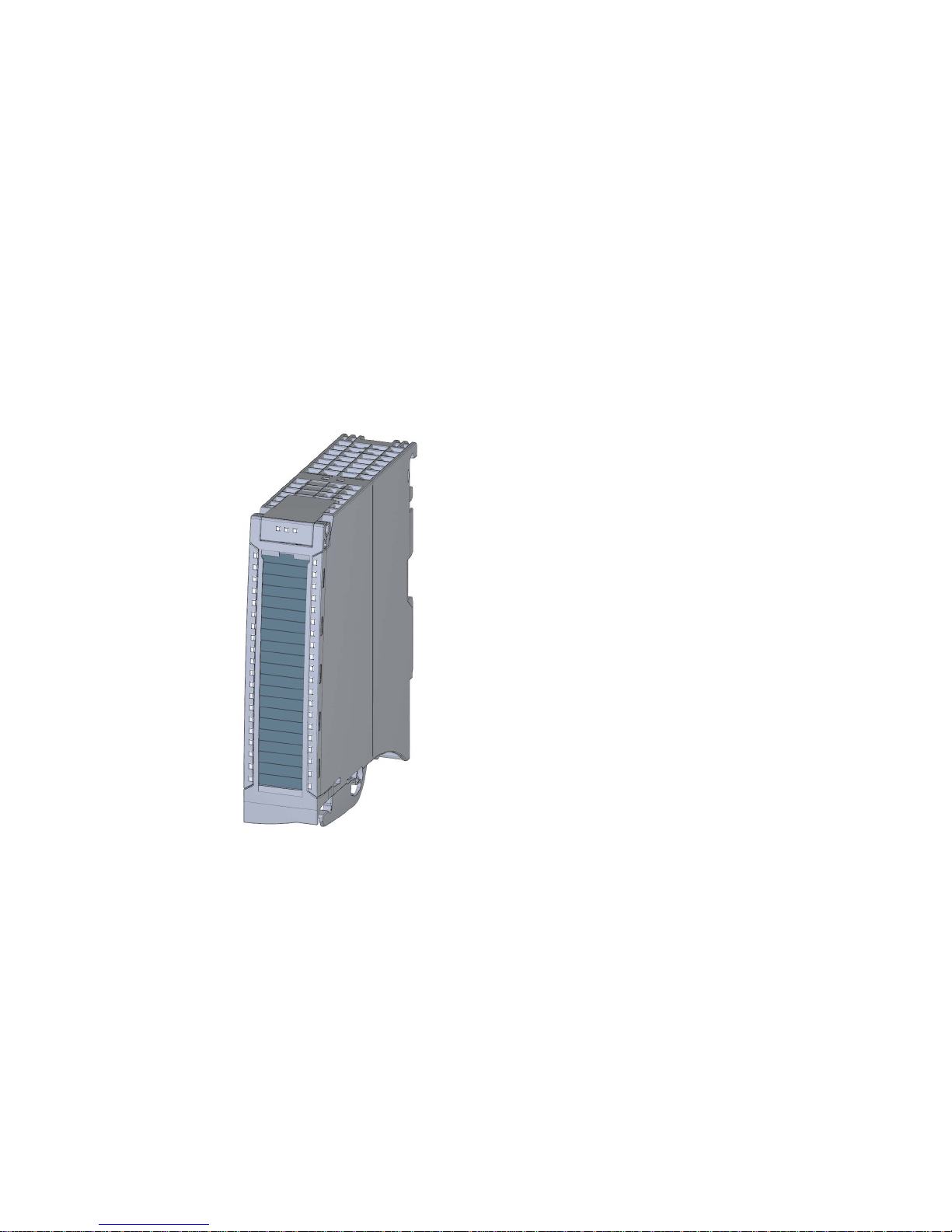
Properties
Article number
6ES7531-7NF00-0AB0
View of the module
Figure 2-1 View of the AI 8xU/I HF module

Product overview
2.1 Properties
Analog Input Module AI 8xU/I HF (6ES7531-7NF00-0AB0)
12 Manual, 09/2016, A5E36649087-AB
Properties
The module has the following technical properties:
● 8 electrically isolated analog inputs
● Voltage measurement type can be set per channel
● Current measurement type can be set per channel
● Two operating modes
– Fast: shortest integration time 2.5 ms
– Standard: shortest integration time 7.5 ms
● Resolution 16 bits including sign
● Configurable diagnostics (per channel)
● Hardware interrupt on limit violation can be set per channel (two low and two high limits
per channel)
The module supports the following functions:
Table 2- 1 Version dependencies of the module functions
Function
Firmware version
of the module
Configuration software
STEP 7
(TIA Portal) as of V13,
SP1 and HSP 0166
GSD file in STEP 7
(TIA Portal) V12 or higher, or
STEP 7 V5.5 SP3 or higher
Firmware update
V1.0.0 or higher
X
--- / X
Identification data I&M0 to I&M3
V1.0.0 or higher X X
Parameter assignment in RUN V1.0.0 or higher X X
Module internal Shared Input (MSI) V1.0.0 or higher X
(PROFINET IO only)
X
(PROFINET IO only)
Configurable submodules / submodules for
Shared Device
V1.0.0 or higher X
(PROFINET IO only)
X
(PROFINET IO only)
Measuring range adjustment
V1.1.0 or higher V14 or higher and HSP
0186
(only PROFINET IO)
X
(PROFINET IO only)
Scaling of measured values
You can configure the module with STEP 7 (TIA Portal) and with a GSD file.

Product overview
2.1 Properties
Analog Input Module AI 8xU/I HF (6ES7531-7NF00-0AB0)
Manual, 09/2016, A5E36649087-AB
13
Accessories
The following accessories are supplied with the module and can also be ordered separately
as spare parts:
● Shield bracket
● Shield terminal
● Power supply element
● Labeling strips
● U connector
● Universal front cover
Other components
The following component can be ordered separately:
Front connectors, including potential jumpers and cable ties
You can find additional information on accessories in the S7-1500/ET 200MP
(http://support.automation.siemens.com/WW/view/en/59191792) system manual.

Product overview
2.2 Functions
Analog Input Module AI 8xU/I HF (6ES7531-7NF00-0AB0)
14 Manual, 09/2016, A5E36649087-AB
2.2
Functions
2.2.1
Measuring range adjustment
Introduction
The measuring range adjustment is available for current and voltage measuring ranges. Live
zero measuring ranges are not supported.
Function
The measuring range adjustment is an adjustment of the measuring range at the sensor.
It allows you to increase the resolution for a configurable part of the measuring range in S7
format.
● You activate the function in STEP 7 (TIA Portal) via the "Measuring range adjustment"
parameter.
● The "Measuring range adjustment high limit" parameter sets the high limit of the
measuring range in mV or μA.
● The "Measuring range adjustment low limit" parameter sets the low limit of the measuring
range in mV or μA.
Note
•
The "Measuring range adjustment" function can be used in combination with the
"Measured value scaling" function, see also Scaling of measured values (Page 17).
•
When the "Measuring range adjustment high limit" and "Measuring range adjustment low
limit" parameters are too close together, resolution may be lost, which means it may no
longer be possible to show every value.
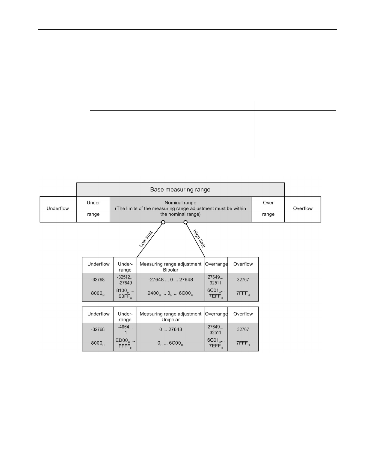
Rules
● The limits of the measuring range adjustment must be selected within the nominal range
of the base measuring range. They are specified in integers.
● The measuring range adjustment is resolved depending on the base measuring range
from 0
H
to 6C00H or 9400H to 6C00H.
● Underranges/overranges apply in accordance with the S7 format and the base measuring
range.
Product overview
2.2 Functions
Analog Input Module AI 8xU/I HF (6ES7531-7NF00-0AB0)
Manual, 09/2016, A5E36649087-AB
15
Example
The following values result, for example:
Table 2- 2 Example of measuring range adjustment
Measuring range adjustment
Measuring range resolution
Bipolar
Unipolar
Base measuring range
±10 V
0 mA to 20 mA
Adjusted measuring range
+2 V to +5 V
+2 mA to +15 mA
Measuring range adjustment high limit 5000 mV
(S7: +27648)
15 mA
(S7: +27648)
Measuring range adjustment low limit 2000 mV
(S7: -27648)
2 mA
(S7: 0)
The following example illustrates the effect of a measuring range adjustment:
Figure 2-2 Example of a measuring range adjustment
Product overview
2.2 Functions
Analog Input Module AI 8xU/I HF (6ES7531-7NF00-0AB0)
16 Manual, 09/2016, A5E36649087-AB
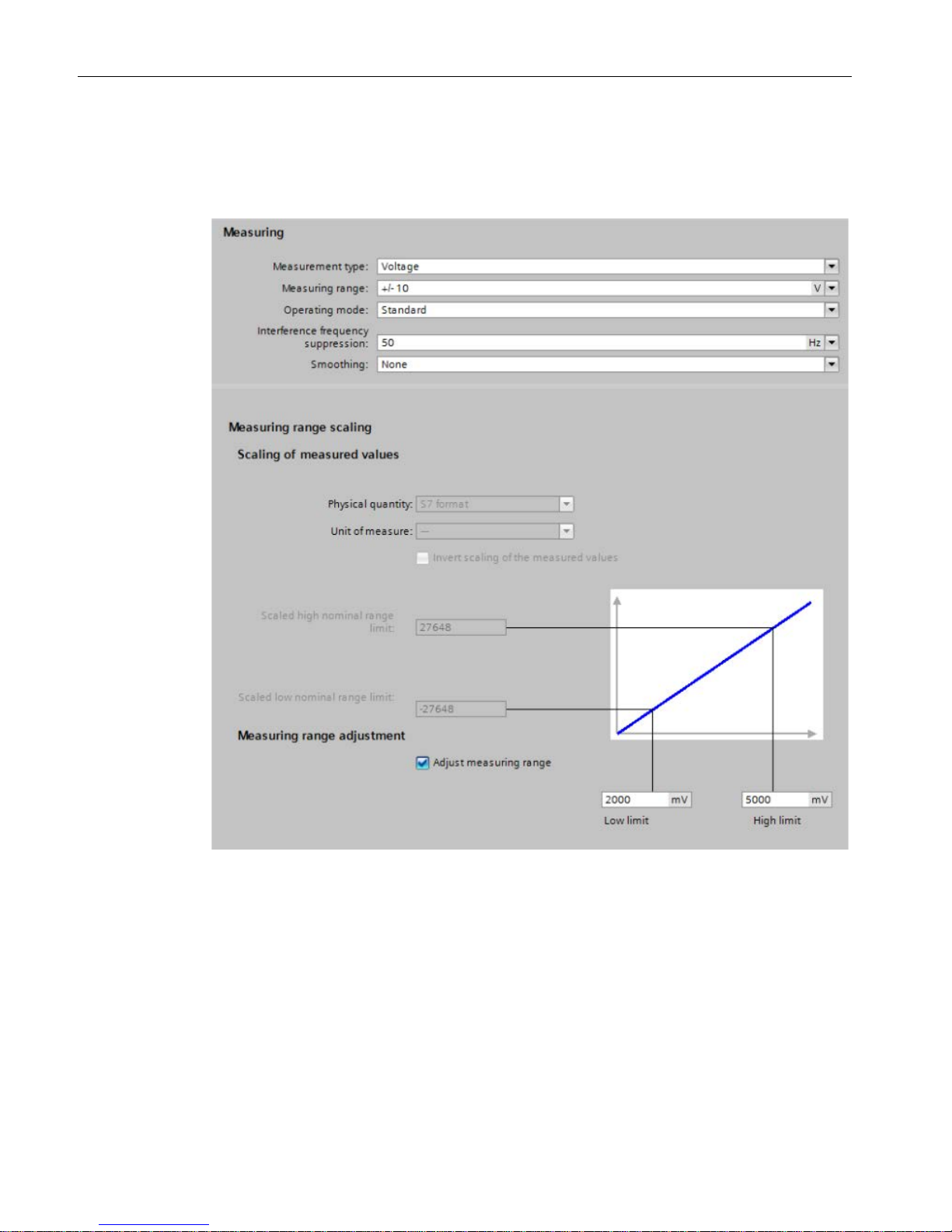
Example of a configuration
The following figure shows an example of a configuration with a measuring range adjustment
of 2000 mV to 5000 mV.
Figure 2-3 Example of a measuring range adjustment in STEP 7 (TIA Portal)

Product overview
2.2 Functions
Analog Input Module AI 8xU/I HF (6ES7531-7NF00-0AB0)
Manual, 09/2016, A5E36649087-AB
17
2.2.2
Scaling of measured values
Introduction
The measured value scaling can be combined with the measuring range adjustment. In this
case, the measuring range is adjusted first and then the representation of the measuring
range is scaled.
Function
With measured value scaling, the user data of the module is displayed in REAL format (32bit floating point) instead of S7 format.
The representation of the measuring range is defined by the following parameters:
● The "Scaled high nominal range limit" parameter sets the desired display value (in REAL
format) for the high nominal range limit of the measuring range.
● The "Scaled low nominal range limit" parameter sets the desired display value (in REAL
format) for the low nominal range limit of the measuring range.
Note
Effects of inversion
•
It is possible to set the "Scaled high nominal range limit" parameter lower than the
"Scaled low nominal range limit" parameter, whereby the representation of the measuring
range will be inverted compared to the terminal value (V, mA).
•
Overflow/underflow and hardware interrupts are always based on representation in
REAL format. A terminal value of > 11.76 V triggered an underflow for an inverted
measured value scaling. Hardware interrupts react similarly.
Substitute value for underflow/overflow
With measured value scaling, the substitute value is minus infinity for underflow (FF80
0000H) and plus infinity for overflow (7F80 0000H).
Resolution at the parameter "Scaled high/low nominal range limit"
Wh
en the Parameter "Scaled high nominal range limit" and "Scaled low nominal range limit"
parameters are too close together, resolution may be lost, which means it may no longer be
possible to show every value.
Product overview
2.2 Functions
Analog Input Module AI 8xU/I HF (6ES7531-7NF00-0AB0)
18 Manual, 09/2016, A5E36649087-AB
Example
The following values result, for example:
Table 2- 3 Example of measured value scaling
Low nominal range limit
High nominal range limit
Base measuring range
-10 V
+10 V
S7 format -27648 +27648
Scaling of measured values
1.00
7.00
As shown in the table, -10 V corresponds to 1.00 and +10 V corresponds to 7.00.
Combination with measuring range adjustment
If the measuring range adjustment is enabled in addition to measured value scaling, first the
measuring range is adjusted and then the representation of the measuring range scaled. The
table below shows an example of the combination of measured value scaling and measuring
range adjustment.
Table 2- 4 Example for a combination of measured value scaling and measuring range adjustment
Low nominal range limit
High nominal range limit
Measuring range adjustment -4000 mV 8000 mV
S7 format
-27648
+27648
Scaling of measured values
1.00
7.00
As shown in the table, -4 V corresponds to 1.00 and +8 V corresponds to 7.00.
Product overview
2.2 Functions
Analog Input Module AI 8xU/I HF (6ES7531-7NF00-0AB0)
Manual, 09/2016, A5E36649087-AB
19
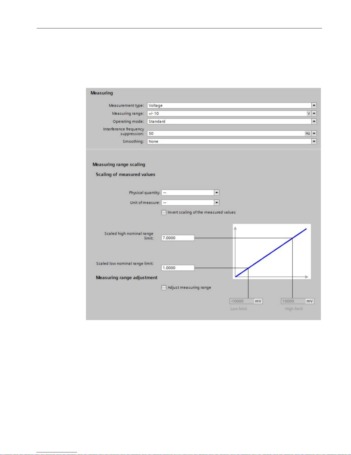
Configuration
The following figures show examples of a configuration in STEP 7 (TIA Portal):
Configuration of measured value scaling
Figure 2-4 Configuration of measured value scaling
Product overview
2.2 Functions
Analog Input Module AI 8xU/I HF (6ES7531-7NF00-0AB0)
20 Manual, 09/2016, A5E36649087-AB
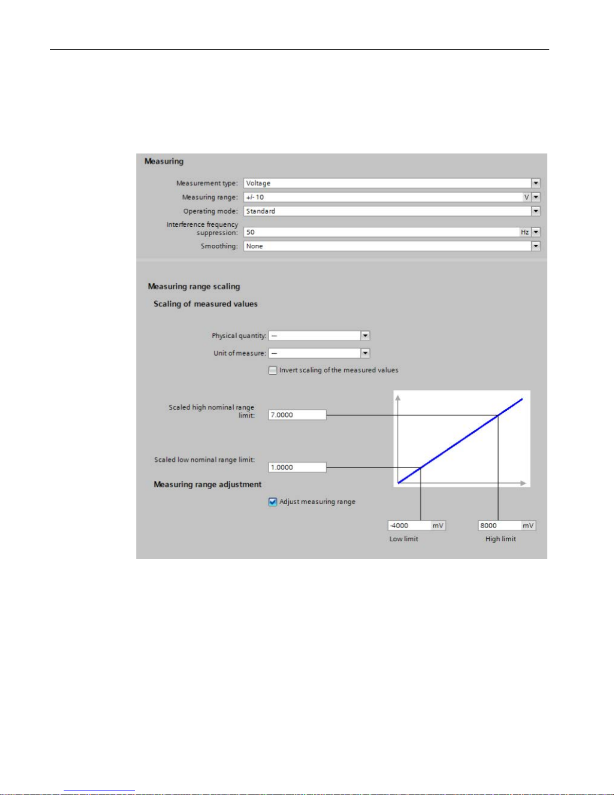
Configuration with measuring range adjustment and measured value scaling
In the configuration example, a measuring range adjustment of -4000 mV to 8000 mV is
displayed and additionally converted to a scaled high and low nominal range limit of 1.00 to
7.00.
Figure 2-5 Configuration with measuring range adjustment and measured value scaling
 Loading...