

Siemens Simatic S7-1500 CPU 1512C-1 PN User Manual

___________________
___________________
___________________
___________________
___________________
___________________
___________________
___________________
___________________
___________________
___________________
SIMATIC
S7-1500
CPU 1512C-1 PN
(6ES7512-1CK01-0AB0)
Manual
12/2017
A5E40898741
Preface
Documentation guide
1
Product overview
2
Technology functions
3
Wiring
4
Parameters/address space
5
Interrupts/diagnostics alarms
6
Technical specifications
7
Dimension drawings
A
Parameter data records
B
Analog value processing
C
-AA

Siemens AG
Division Digital Factory
Po
90026 NÜRNBERG
GERMANY
A5E40898741-AA
Ⓟ
Copyright © Siemens AG 2017.
All rights reserved
Legal information
Warning notice system
DANGER
indicates that death or severe personal injury will result if proper precautions are not taken.
WARNING
indicates that death or severe personal injury may result if proper precautions are not taken.
CAUTION
indicates that minor personal injury can result if proper precautions are not taken.
NOTICE
indicates that property damage can result if proper precautions are not taken.
Qualified Personnel
personnel qualified
Proper use of Siemens products
WARNING
Siemens products may only be used for the applications described in the catalog and in the relevant technical
maintenance are required to ensure that the products operate safely and without any problems. The permissible
ambient conditions must be complied with. The information in the relevant documentation must be observed.
Trademarks
Disclaimer of Liability
This manual contains notices you have to observe in order to ensure your personal safety, as well as to prevent
damage to property. The notices referring to your personal safety are highlighted in the manual by a safety alert
symbol, notices referring only to property damage have no safety alert symbol. These notices shown below are
graded according to the degree of danger.
If more than one degree of danger is present, the warning notice representing the highest degree of danger will
be used. A notice warning of injury to persons with a safety alert symbol may also include a warning relating to
property damage.
The product/system described in this documentation may be operated only by
task in accordance with the relevant documentation, in particular its warning notices and safety instructions.
Qualified personnel are those who, based on their training and experience, are capable of identifying risks and
avoiding potential hazards when working with these products/systems.
Note the following:
documentation. If products and components from other manufacturers are used, these must be recommended
or approved by Siemens. Proper transport, storage, installation, assembly, commissioning, operation and
All names identified by ® are registered trademarks of Siemens AG. The remaining trademarks in this publication
may be trademarks whose use by third parties for their own purposes could violate the rights of the owner.
We have reviewed the contents of this publication to ensure consistency with the hardware and software
described. Since variance cannot be precluded entirely, we cannot guarantee full consistency. However, the
information in this publication is reviewed regularly and any necessary corrections are included in subsequent
editions.
for the specific
stfach 48 48
12/2017 Subject to change

Preface
Purpose of the documentation
Conventions
Note
A note contains important information on the product described in the documentation, on the
handling of the product or on the section of the documentation to
should be paid.
Security information
This manual supplements the system manual of the S7-1500 automation system /
ET 200MP distributed I/O system as well as the function manuals. This manual contains a
description of the module-specific information. The system-related functions are described in
the system manual. Cross-system functions are described in the function manuals.
The information provided in this manual and the system manual enables you to commission
the CPU 1512C-1 PN.
STEP 7: In this documentation, "STEP 7" is used as a synonym for all versions of the
configuration and programming software "STEP 7 (TIA Portal)".
Please also observe notes marked as follows:
Siemens provides products and solutions with industrial security functions that support the
secure operation of plants, systems, machines and networks.
In order to protect plants, systems, machines and networks against cyber threats, it is
necessary to implement – and continuously maintain – a holistic, state-of-the-art industrial
security concept. Siemens’ products and solutions only form one element of such a concept.
Customer is responsible to prevent unauthorized access to its plants, systems, machines
and networks. Systems, machines and components should only be connected to the
enterprise network or the internet if and to the extent necessary and with appropriate security
measures (e.g. use of firewalls and network segmentation) in place.
Additionally, Siemens’ guidance on appropriate security measures should be taken into
account. For more information about industrial security, please visit
(http://www.siemens.com/industrialsecurity).
Siemens’ products and solutions undergo continuous development to make them more
secure. Siemens strongly recommends to apply product updates as soon as available and to
always use the latest product versions. Use of product versions that are no longer supported,
and failure to apply latest updates may increase customer’s exposure to cyber threats.
To stay informed about product updates, subscribe to the Siemens Industrial Security RSS
Feed under (http://www.siemens.com/industrialsecurity).
which particular attention
CPU 1512C-1 PN (6ES7512-1CK01-0AB0)
4 Manual, 12/2017, A5E40898741-AA

Preface
Siemens Industry Online Support
Product support
Application examples
Services
Forums
mySupport
Industry Mall
You can find current information on the following topics quickly and easily here:
●
All the information and extensive know-how on your product, technical specifications,
FAQs, certificates, downloads, and manuals.
●
Tools and examples to solve your automation tasks – as well as function blocks,
performance information and videos.
●
Information about Industry Services, Field Services, Technical Support, spare parts and
training offers.
●
For answers and solutions concerning automation technology.
●
Your personal working area in Industry Online Support for messages, support queries,
and configurable documents.
This information is provided by the Siemens Industry Online Support in the Internet
(https://support.industry.siemens.com).
The Industry Mall is the catalog and order system of Siemens AG for automation and drive
solutions on the basis of Totally Integrated Automation (TIA) and Totally Integrated Power
(TIP).
Catalogs for all the products in automation and drives are available on the Internet
(https://mall.industry.siemens.com).
CPU 1512C-1 PN (6ES7512-1CK01-0AB0)
Manual, 12/2017, A5E40898741-AA
5

Table of contents
Preface ................................................................................................................................................... 4
1 Documentation guide .............................................................................................................................. 9
2 Product overview .................................................................................................................................. 13
3 Technology functions ............................................................................................................................ 42
2.1 Applications of the S7-1500 CPUs......................................................................................... 13
2.2 Hardware properties and firmware functions ......................................................................... 20
2.2.1 Hardware properties of the CPU part .................................................................................... 21
2.2.2 Firmware functions of the CPU part ....................................................................................... 23
2.2.3 Hardware properties of the analog on-board I/O module ...................................................... 27
2.2.4 Firmware functions of the analog on-board I/O module......................................................... 30
2.2.5 Hardware properties of the digital on-board I/O module ........................................................ 31
2.2.6 Firmware functions of the digital on-board I/O module .......................................................... 34
2.3 Operator controls and display elements ................................................................................ 36
2.3.1 Front view with closed front panel.......................................................................................... 36
2.3.2 Front view of the CPU without front panel and view from below ........................................... 38
2.3.3 Rear view ............................................................................................................................... 40
2.4 Operating mode buttons ........................................................................................................ 41
3.1 High-speed counters .............................................................................................................. 42
3.1.1 Functions ................................................................................................................................ 43
3.1.1.1 Counting ................................................................................................................................. 43
3.1.1.2 Measuring .............................................................................................................................. 44
3.1.1.3 Position detection for motion control ...................................................................................... 45
3.1.1.4 Additional functions ................................................................................................................ 46
3.1.2 Configuring the high-speed counters ..................................................................................... 47
3.1.2.1 General .................................................................................................................................. 47
3.1.2.2 Assignment of the control interface of the high-speed counters ............................................ 47
3.1.2.3 Assignment of the feedback interface of the high-speed counters ........................................ 50
3.2 Pulse generators .................................................................................................................... 51
3.2.1 Operating modes.................................................................................................................... 51
3.2.1.1 Operating mode: Pulse-width modulation (PWM) .................................................................. 51
3.2.1.2 Operating mode: Frequency output ....................................................................................... 58
3.2.1.3 Operating mode: PTO ............................................................................................................ 62
3.2.2 Functions ................................................................................................................................ 67
3.2.2.1 Function: High-speed output .................................................................................................. 67
3.2.2.2 Function: Direct control of the pulse output (DQA) ................................................................ 68
3.2.3 Configuring the PWM and frequency output modes .............................................................. 69
3.2.3.1 Assignment of the control interface........................................................................................ 69
3.2.3.2 Handling the SLOT parameter (control interface) .................................................................. 71
3.2.3.3 Assignment of the feedback interface .................................................................................... 75
CPU 1512C-1 PN (6ES7512-1CK01-0AB0)
6 Manual, 12/2017, A5E40898741-AA

Table of contents
4 Wiring ................................................................................................................................................... 77
5 Parameters/address space ................................................................................................................. 114
6 Interrupts/diagnostics alarms ............................................................................................................... 127
7 Technical specifications ...................................................................................................................... 141
A Dimension drawings ............................................................................................................................ 164
4.1 Supply voltage ........................................................................................................................ 77
4.2 PROFINET interfaces ............................................................................................................. 78
4.3 Terminal and block diagrams .................................................................................................. 80
4.3.1 Block diagram of the CPU part ............................................................................................... 80
4.3.2 Terminal and block diagram of the analog on-board I/O ........................................................ 81
4.3.3 Terminal and block diagram of the digital on-board I/O .......................................................... 90
4.3.4 Addresses of the high-speed counters ................................................................................. 104
4.3.5 Addresses of the pulse generators in the Pulse Width Modulation (PWM) and
Frequency Output modes ..................................................................................................... 107
4.3.6 Addresses of pulse generators in the PTO mode ................................................................. 108
4.3.7 Interconnection overview of the inputs ................................................................................. 109
4.3.8 Interconnection overview of outputs ..................................................................................... 111
5.1 Address space of the analog on-board I/O ........................................................................... 114
5.2 Address space of the digital on-board I/O ............................................................................ 116
5.3 Address space of the pulse generators ................................................................................ 119
5.4 Measurement types and measuring ranges of the analog on-board I/O .............................. 120
5.5 Output type and output ranges of the analog on-board I/O .................................................. 121
5.6 Parameters of the analog on-board I/O ................................................................................ 122
5.7 Parameters of the digital on-board I/O .................................................................................. 125
6.1 Status and error displays ...................................................................................................... 127
6.1.1 Status and error displays of the CPU part ............................................................................ 127
6.1.2 Status and error displays of the analog on-board I/O ........................................................... 130
6.1.3 Status and error displays of the digital on-board I/O ............................................................ 132
6.2 Interrupts and diagnostics ..................................................................................................... 134
6.2.1 Interrupts and diagnostics of the CPU part ........................................................................... 134
6.2.2 Interrupts and diagnostics of the analog on-board I/O ......................................................... 135
6.2.3 Interrupts and diagnostics of the digital on-board I/O ........................................................... 138
CPU 1512C-1 PN (6ES7512-1CK01-0AB0)
Manual, 12/2017, A5E40898741-AA
7

Table of contents
B Parameter data records ....................................................................................................................... 166
C Analog value processing ...................................................................................................................... 189
B.1 Parameter assignment and structure of the parameter data records of the analog on-
board I/O .............................................................................................................................. 166
B.2 Structure of a data record for input channels of the analog on-board I/O ........................... 166
B.3 Structure of a data record for output channels of the analog on-board I/O ......................... 172
B.4 Parameter assignment and structure of the parameter data records of the digital on-
board I/O .............................................................................................................................. 175
B.5 Structure of a data record for input channels of the digital on-board I/O ............................. 176
B.6 Structure of a data record for output channels of the digital on-board I/O........................... 178
B.7 Parameter data records of the high-speed counters ........................................................... 180
B.8 Parameter data records (PWM) ........................................................................................... 187
C.1 Conversion method .............................................................................................................. 189
C.2 Representation of analog values ......................................................................................... 196
C.3 Representation of input ranges ............................................................................................ 197
C.3.1 Representation of analog values in voltage measuring ranges ........................................... 198
C.3.2 Representation of analog values in current measuring ranges ........................................... 199
C.3.3 Representation of the analog values of resistance-type sensors/resistance-type
thermometers ....................................................................................................................... 200
C.3.4 Measured values for wire break diagnostics ........................................................................ 202
C.4 Representation of output ranges.......................................................................................... 203
C.4.1 Representation of analog values in the voltage output ranges ............................................ 204
C.4.2 Representation of analog values in the current output ranges ............................................ 205
CPU 1512C-1 PN (6ES7512-1CK01-0AB0)
8 Manual, 12/2017, A5E40898741-AA
1
Basic information
Device information
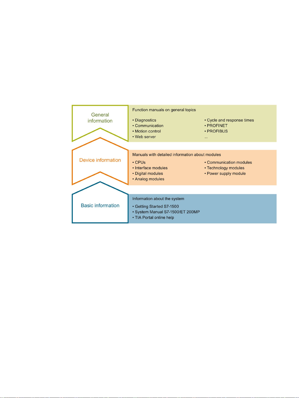
The documentation for the SIMATIC S7-1500 automation system and the SIMATIC
ET 200MP distributed I/O system is arranged into three areas.
This arrangement enables you to access the specific content you require.
The System Manual and Getting Started describe in detail the configuration, installation,
wiring and commissioning of the SIMATIC S7-1500 and ET 200MP systems. The STEP 7
online help supports you in the configuration and programming.
Product manuals contain a compact description of the module-specific information, such as
properties, wiring diagrams, characteristics and technical specifications.
CPU 1512C-1 PN (6ES7512-1CK01-0AB0)
Manual, 12/2017, A5E40898741-AA
9

Documentation guide
General information
Manual Collection S7-1500/ET 200MP
SIMATIC S7-1500 comparison list for programming languages
"mySupport"
"mySupport" - Documentation
The function manuals contain detailed descriptions on general topics regarding the SIMATIC
S7-1500 and ET 200MP systems, e.g. diagnostics, communication, motion control, Web
server, OPC UA.
You can download the documentation free of charge from the Internet
(http://w3.siemens.com/mcms/industrial-automation-systems-simatic/en/manual-
overview/Pages/Default.aspx).
Changes and supplements to the manuals are documented in a Product Information.
You can download the product information free of charge from the Internet
(https://support.industry.siemens.com/cs/us/en/view/68052815).
The Manual Collection contains the complete documentation on the SIMATIC S7-1500
automation system and the ET 200MP distributed I/O system gathered together in one file.
You can find the Manual Collection on the Internet
(https://support.industry.siemens.com/cs/ww/en/view/86140384).
The comparison list contains an overview of which instructions and functions you can use for
which controller families.
You can find the comparison list on the Internet
(https://support.industry.siemens.com/cs/ww/en/view/86630375).
With "mySupport", your personal workspace, you make the best out of your Industry Online
Support.
In "mySupport", you can save filters, favorites and tags, request CAx data and compile your
personal library in the Documentation area. In addition, your data is already filled out in
support requests and you can get an overview of your current requests at any time.
You must register once to use the full functionality of "mySupport".
You can find "mySupport" on the Internet (https://support.industry.siemens.com/My/ww/en).
In the Documentation area in "mySupport" you can combine entire manuals or only parts of
these to your own manual.
You can export the manual as PDF file or in a format that can be edited later.
You can find "mySupport" - Documentation on the Internet
(http://support.industry.siemens.com/My/ww/en/documentation).
CPU 1512C-1 PN (6ES7512-1CK01-0AB0)
10 Manual, 12/2017, A5E40898741-AA

Documentation guide
"mySupport" - CAx data
Application examples
TIA Selection Tool
In the CAx data area in "mySupport", you can access the current product data for your CAx
or CAe system.
You configure your own download package with a few clicks.
In doing so you can select:
● Product images, 2D dimension drawings, 3D models, internal circuit diagrams, EPLAN
macro files
● Manuals, characteristics, operating manuals, certificates
● Product master data
You can find "mySupport" - CAx data on the Internet
(http://support.industry.siemens.com/my/ww/en/CAxOnline).
The application examples support you with various tools and examples for solving your
automation tasks. Solutions are shown in interplay with multiple components in the system separated from the focus on individual products.
You will find the application examples on the Internet
(https://support.industry.siemens.com/sc/ww/en/sc/2054).
With the TIA Selection Tool, you can select, configure and order devices for Totally
Integrated Automation (TIA).
This tool is the successor of the SIMATIC Selection Tool and combines the known
configurators for automation technology into one tool.
With the TIA Selection Tool, you can generate a complete order list from your product
selection or product configuration.
You can find the TIA Selection Tool on the Internet
(http://w3.siemens.com/mcms/topics/en/simatic/tia-selection-tool).
CPU 1512C-1 PN (6ES7512-1CK01-0AB0)
Manual, 12/2017, A5E40898741-AA
11

Documentation guide
SIMATIC Automation Tool
PRONETA
You can use the SIMATIC Automation Tool to perform commissioning and maintenance
activities simultaneously on various SIMATIC S7 stations as a bulk operation independent of
the TIA Portal.
General function overview:
● Network browsing and creation of a table showing the accessible devices in the network.
● Flashing of device LEDs or HMI display to locate a device
● Downloading of addresses (IP, subnet, gateway) to a device
● Downloading the PROFINET name (station name) to a device
● Placing a CPU in RUN or STOP mode
● Setting the time in a CPU to the current time of your PG/PC
● Downloading a new program to a CPU or an HMI device
● Downloading from CPU, downloading to CPU or deleting recipe data from a CPU
● Downloading from CPU or deleting data log data from a CPU
● Backup/restore of data from/to a backup file for CPUs and HMI devices
● Downloading service data from a CPU
● Reading the diagnostics buffer of a CPU
● Performing a CPU memory reset
● Resetting devices to factory settings
● Downloading a firmware update to a device
You can find the SIMATIC Automation Tool on the Internet
(https://support.industry.siemens.com/cs/ww/en/view/98161300).
With SIEMENS PRONETA (PROFINET network analysis), you analyze the PROFINET
network during commissioning. PRONETA features two core functions:
● The topology overview independently scans PROFINET network and all connected
components.
● The IO check is a fast test of the wiring and the module configuration of a system.
You can find SIEMENS PRONETA on the Internet
(https://support.industry.siemens.com/cs/ww/en/view/67460624).
CPU 1512C-1 PN (6ES7512-1CK01-0AB0)
12 Manual, 12/2017, A5E40898741-AA

2
2.1
Applications of the S7-1500 CPUs
Application area
The SIMATIC S7-1500 is the modular control system for numerous automation applications
in discrete automation.
The modular and fanless design, the simple implementation of distributed structures and the
user-friendly handling transform the SIMATIC S7-1500 into a cost-effective and convenient
solution for various tasks.
Areas of application of the SIMATIC S7-1500 are, for example:
● Special-purpose machines
● Textile machinery
● Packaging machines
● General mechanical engineering
● Controller engineering
● Machine tool engineering
● Installation engineering
● Electrical industry and crafts
● Automotive
● Water/waste water
● Food & Beverage
Areas of application of the SIMATIC S7-1500T are, for example:
● Packaging machines
● Converting application
● Assembly automation
Several CPUs with various levels of performance and a comprehensive range of modules
with many convenient features are available. Fail-safe CPUs enable use in fail-safe
applications. The modular design allows you to use only the modules that you need for your
application. The controller can be retrofitted with additional modules at any time to expand its
range of tasks.
The high immunity to noise and high resistance to shock and vibration stress make the
SIMATIC S7-1500 suitable for universal use.
CPU 1512C-1 PN (6ES7512-1CK01-0AB0)
Manual, 12/2017, A5E40898741-AA
13

Product overview
Performance segments of the standard, compact, fail-safe and technology CPUs
CPU
Performance segment
PROFIBUS
interfaces
PROFINET I
O RT/IRT
interface
PROFINET
IO RT inter-
face
PROFINET
basic func-
tionality
Work
memory
Processing
time for bit
operations
medium-sized applications
sized applications
medium-sized applications
cation tasks
cation tasks
reaction times
CPU
Performance segment
PROFIBUS
interfaces
PROFINET
IO RT/IRT
interfaces
PROFINET
IO RT
interface
PROFINET
basic functionality
Work memory
Pro-
cessing
time for bit
operations
medium applications
CPU
Performance segment
PROFIBUS
interfaces
PROFINET
IO RT/IRT
interfaces
PROFINET
IO RT
interface
PROFINET
basic func-
tionality
Work memory
Pro-
cessing
time for bit
operations
tions
applications
2.1 Applications of the S7-1500 CPUs
The CPUs can be used for smaller and medium-sized applications, as well as for the highend range of machine and plant automation.
Table 2- 1 Standard CPUs
CPU 1511-1 PN Standard CPU for small- to
CPU 1513-1 PN Standard CPU for medium-
CPU 1515-2 PN Standard CPU for small- to
CPU 1516-3
PN/DP
CPU 1517-3
PN/DP
CPU 1518-4
PN/DP
CPU 1518-4
PN/DP MFP
Standard CPU for high-end
applications and communi-
Standard CPU for high-end
applications and communi-
Standard CPU for highperformance applications,
demanding communications tasks and very short
Table 2- 2 Compact CPUs
CPU 1511C-1 PN Compact CPU for small to
-- 1 -- -- 1.15 MB 60 ns
-- 1 -- -- 1.8 MB 40 ns
-- 1 1 -- 3.5 MB 30 ns
1 1 1 -- 6 MB 10 ns
1 1 1 -- 10 MB 2 ns
1 1 1 1 24 MB 1 ns
-- 1 -- -- 1.175 MB 60 ns
CPU 1512C-1 PN Compact CPU for medium
Table 2- 3 Fail-safe CPUs
CPU 1511F-1 PN Fail-safe CPU for smaller
CPU 1511TF-1 PN Fail-safe technology CPU
CPU 1512C-1 PN (6ES7512-1CK01-0AB0)
14 Manual, 12/2017, A5E40898741-AA
applications
-- 1 -- -- 1.25 MB 48 ns
-- 1 -- -- 1.225 MB 60 ns
to medium-sized applica-
-- 1 -- -- 1.225 MB 60 ns
for small to mid-range

Product overview
CPU
Performance segment
PROFIBUS
interfaces
PROFINET
IO RT/IRT
interfaces
PROFINET
IO RT
interface
PROFINET
basic func-
tionality
Work memory
Pro-
cessing
time for bit
operations
sized applications
sized to large applications
and communication tasks
munications tasks
and communication tasks
munications tasks
reaction times
CPU
Performance segment
PROFIBUS
interfaces
PROFINET
IO RT/IRT
interfaces
PROFINET
IO RT
interface
PROFINET
basic func-
tionality
Work memory
Pro-
cessing
time for bit
operations
range to large applications
communication tasks
communication tasks
PN/DP
2.1 Applications of the S7-1500 CPUs
CPU 1513F-1 PN Fail-safe CPU for medium-
CPU 1515F-2 PN Fail-safe CPU for medium-
CPU 1515TF-2
PN
CPU 1516F-3
PN/DP
CPU 1516TF-3
PN/DP
CPU 1517F-3
PN/DP
CPU 1517TF-3
PN/DP
CPU 1518F-4
PN/DP
CPU 1518F-4
PN/DP MFP
Fail-safe technology CPU
for demanding applications
Fail-safe CPU for demanding applications and com-
Fail-safe technology CPU
for demanding applications
Fail-safe CPU for demanding applications and com-
Fail-safe technology CPU
for demanding applications
and communication tasks
Fail-safe CPU for highperformance applications,
demanding communications tasks and very short
-- 1 -- -- 1.95 MB 40 ns
-- 1 1 -- 3.75 MB 30 ns
-- 1 1 -- 3.75 MB 30 ns
1 1 1 -- 6.5 MB 10 ns
1 1 1 -- 6.5 MB 10 ns
1 1 1
1 1 1
1 1 1 1 26 MB 1 ns
-- 11 MB
-- 11 MB
2 ns
2 ns
Table 2- 4 Technology CPUs
CPU 1511T-1 PN Technology CPU for small-
CPU 1515T-2 PN Technology CPU for mid-
CPU 1516T-3
PN/DP
CPU 1517T-3
PN/DP
CPU 1511TF-1
PN
CPU 1515TF-2
PN
CPU 1516TF-3
PN/DP
CPU 1517TF-3
to medium-sized applications
Technology CPU for highend applications and
Technology CPU for highend applications and
These CPUs are described in the fail-safe CPUs
-- 1 -- -- 1.225 MB 60 ns
-- 1 1 -- 3.75 MB 30 ns
1 1 1 -- 6.5 MB 10 ns
1 1 1 -- 11 MB 2 ns
Manual, 12/2017, A5E40898741-AA
CPU 1512C-1 PN (6ES7512-1CK01-0AB0)
15

Product overview
Performance segments of compact CPUs
CPU 1511C-1 PN
CPU 1512C-1 PN
Integrated analog inputs/outputs
5 inputs/2 outputs
5 inputs/2 outputs
High-speed counters 6 6
Frequency meter
6 (max. 100 kHz)
6 (max. 100 kHz)
Period duration measurement
6 channels
6 channels
Max. 4 (up to 100 kHz)
Max. 4 (up to 100 kHz)
Pulse Train Output (PTO output)
Max. 4 (up to 100 kHz)
Max. 4 (up to 100 kHz)
Frequency output
Up to 100 kHz
Up to 100 kHz
2.1 Applications of the S7-1500 CPUs
The compact CPUs can be used for smaller to medium-sized applications and have an
integrated analog and digital on-board I/O as well as integrated technology functions. The
following table shows the differences in performance between the two compact CPUs.
Integrated digital inputs/outputs 16 inputs/16 outputs 32 inputs/32 outputs
Pulse width modulation (PWM output)
CPU 1512C-1 PN (6ES7512-1CK01-0AB0)
16 Manual, 12/2017, A5E40898741-AA

Product overview
Integrated Motion Control technology functions
All CPUs of SIMATIC S7-1500
The technology CPUs of the SIMATIC S7-1500
The technology CPUs of the SIMATIC S7-1500
Additional integrated technology functions
2.1 Applications of the S7-1500 CPUs
support Motion Control technology functions. STEP 7 offers
Motion Control instructions standardized according to PLCopen for configuring and
connecting a drive to the CPU.
S7-1500 Motion Control supports the following technology objects:
● Speed-controlled axes
● Positioning axes
● Synchronous axes
● External encoders
● Output cams
● Cam tracks
● Measuring inputs
offer enhanced Motion Control functions:
● Advanced synchronization functions
– Synchronization with specification of the synchronous position
– Actual value coupling
– Shifting of the master value at following axis
– Camming
● Up to 4 encoders or measuring systems as actual position for position control
objects: – Cam – Kinematics
● Cam
● Kinematics
● Controlling of kinematics, such as
– Cartesian portals
– Roller pickers
– Delta pickers
– SCARA
Due to the supported technology functions, the S7-1500T CPUs are suitable for controlling
packaging machines, converting applications, assembly automation, etc.
For effective commissioning, diagnostics and fast optimization of drives and controls, the
SIMATIC S7-1500 controller family offers extensive trace functions for all CPU tags.
In addition to drive integration, the SIMATIC S7-1500 has a PID compact closed-loop
controller; easy-to-configure blocks allow automatic optimization of the controller parameters
for optimized control quality.
additionally support the following technology
CPU 1512C-1 PN (6ES7512-1CK01-0AB0)
Manual, 12/2017, A5E40898741-AA
17

Product overview
Other technology functions
Security Integrated
Safety Integrated
2.1 Applications of the S7-1500 CPUs
Technology modules also implement functions such as high-speed counting, position
detection, measuring functions and pulse generators (PTO, PWM and frequency output). For
compact CPU 1511C-1 PN and CPU 1512C-1 PN CPUs, these functions are already
integrated and can be implemented without additional technology modules.
SIWAREX is a versatile and flexible weighing module which you can use as a static scale for
operation.
In conjunction with STEP 7 (TIA Portal), each CPU offers password-based know-how
protection against unauthorized reading out or modification of the program blocks.
The copy protection provides reliable protection against unauthorized reproduction of
program blocks. With copy protection, individual blocks on the SIMATIC memory card are
linked to its serial number so that the block can only be executed if the configured memory
card is inserted in the CPU.
In addition, four different authorization levels in the CPUs can be used to assign different
access rights to various user groups.
Improved manipulation protection allows the CPUs to detect changed or unauthorized
transfers of the engineering data.
The use of an Ethernet CP (CP 1543-1) provides the user with additional access protection
by means of a firewall and/or the option of secured VPN connections.
The fail-safe CPUs are intended for users who want to implement demanding standard and
fail-safe applications both centrally and distributed.
These fail-safe CPUs allow the processing of standard and safety programs on a single
CPU. This allows fail-safe data to be evaluated in the standard user program. The integration
also provides the system advantages and the extensive functionality of SIMATIC for fail-safe
applications.
The fail-safe CPUs are certified for use in safety mode up to:
● Safety class (Safety Integrity Level) SIL 3 according to IEC 61508:2010
● Performance Level (PL) e and Category 4 according to ISO 13849-1:2006 or according to
EN ISO 13849-1:2008
Additional password protection for F-configuration and F-program is set up for IT security.
CPU 1512C-1 PN (6ES7512-1CK01-0AB0)
18 Manual, 12/2017, A5E40898741-AA

Product overview
Design and handling
System diagnostics and messages
2.1 Applications of the S7-1500 CPUs
All CPUs of the SIMATIC S7-1500 product series feature a display with plain text
information. The display provides the user with information on the order numbers, firmware
version, and serial number of all connected modules. In addition, the IP address of the CPU
and other network settings can be adapted locally without a programming device. Error
messages are immediately shown on the display in plain text. In the case of servicing, plant
downtimes are minimized by quick access to diagnostics alarms. Detailed information about
this and a multitude of other display functions is available in the SIMATIC S7-1500 Display
Simulator (http://www.automation.siemens.com/salesmaterial-as/interactive-manuals/getting-
started_simatic-s7-1500/disp_tool/start_en.html).
Uniform front connectors for all modules and integrated potential jumpers for flexible
formation of potential groups simplifies storage. Additional components such as circuit
breakers, relays, etc., can be installed quickly and easily, since a DIN rail is implemented in
the rail of the S7-1500. The CPUs of the SIMATIC S7-1500 product series can be expanded
centrally and modularly with signal modules. Space-saving expansion enables flexible
adaptation to each application.
The system cabling for digital signal modules enables fast and clear connection to sensors
and actuators from the field (fully modular connection consisting of front connector modules,
connection cables and I/O modules), as well as the easy wiring inside the control cabinet
(flexible connection consisting of front connectors with assembled single conductors).
Integrated system diagnostics is enabled by default for the CPUs. The different types of
diagnostics are configured instead of programmed. System diagnostics information is shown
uniformly and in plain text on the display of the CPU, in STEP 7 (TIA Portal), on the HMI and
on the Web server, even for alarms related to drives. This information is available in RUN
mode, but also in STOP mode of the CPU. The diagnostics information is updated
automatically when you configure new hardware components.
The CPU is available as a central interrupt server in up to three project languages. The HMI
takes over the display in the project languages specified for the CPU. If you require message
texts in additional languages, you can load these via the configured connection to your HMI.
The CPU, STEP 7 and your HMI guarantee data consistency without additional engineering
steps. The maintenance work is easier.
CPU 1512C-1 PN (6ES7512-1CK01-0AB0)
Manual, 12/2017, A5E40898741-AA
19

Product overview
2.2
Hardware properties and firmware functions
properties
functions
Article number
Accessories
2.2 Hardware properties and firmware functions
The CPU 1512C-1 PN consists of a CPU part, an analog on-board I/O module (X10) and a
digital on-board I/O module (X11 and X12). When configured in the TIA Portal, the compact
CPU therefore occupies a single shared slot (slot 1).
The properties and functions of the CPU part and the analog and digital on-board I/O
modules can be found in the subsections below. The
features of the CPU part and the analog and digital on-board I/O modules. The
describe the functions of the firmware of the CPU part and the analog and digital on-board
I/O modules.
describe the hardware
6ES7512-1CK01-0AB0
The following accessories are included in the scope of delivery and can also be ordered
separately as spare parts:
● 3 x front connector (push-in terminals) including cable ties
● 3 x shield clamp
● 3 x shield terminal
● 3 x infeed element (push-in terminals)
● 3 x labeling strip
● 3 x universal front cover
For more information on accessories, refer to the S7-1500, ET 200MP system manual
(http://support.automation.siemens.com/WW/view/en/59191792).
CPU 1512C-1 PN (6ES7512-1CK01-0AB0)
20 Manual, 12/2017, A5E40898741-AA
Product overview
2.2.1
Hardware properties of the CPU part
View of the CPU
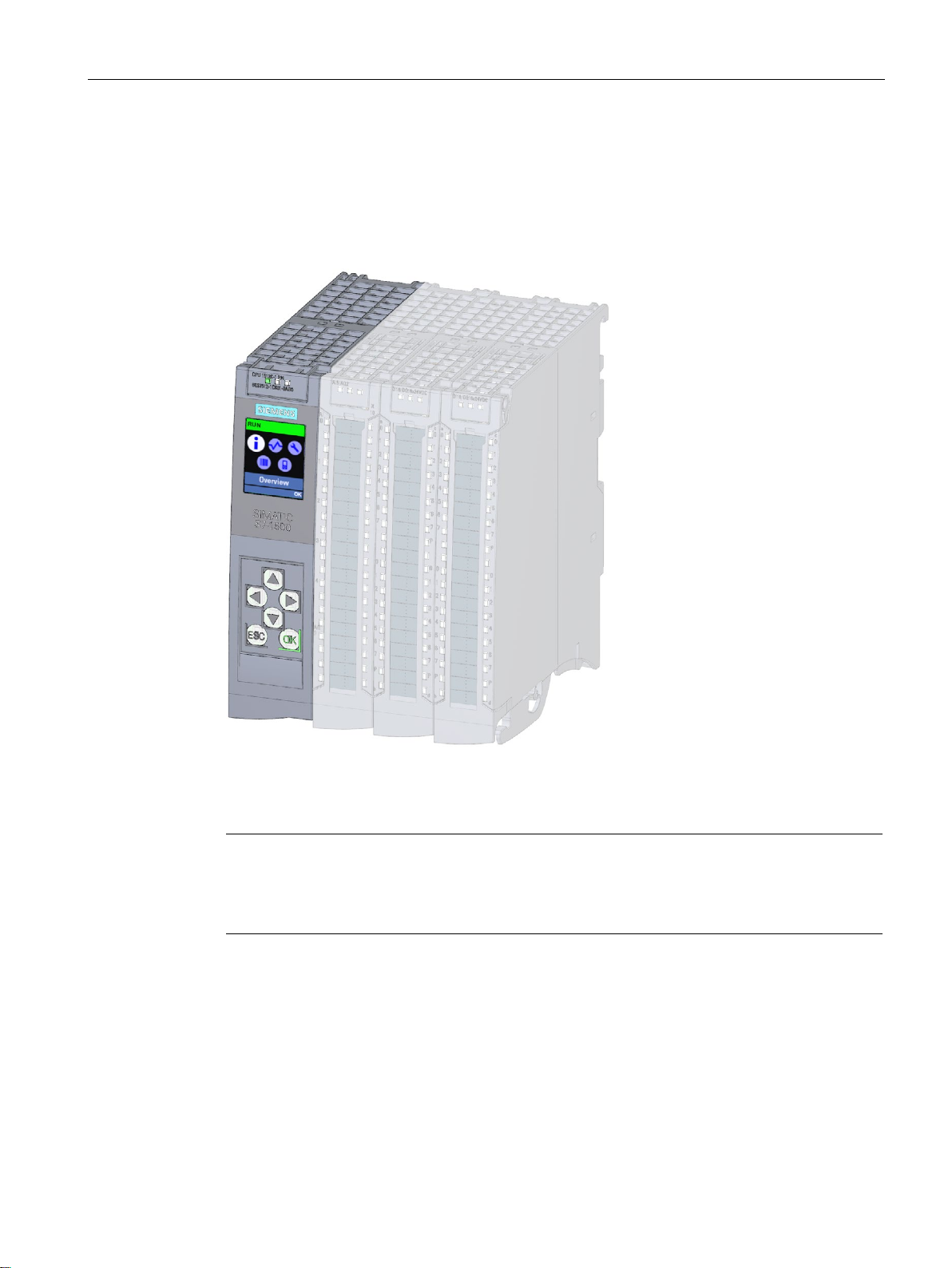
Note
Protective film
Note that a protective film is attached to the display of the CPU when shipped from the
factory. Remove the protective film if necessary.
2.2 Hardware properties and firmware functions
The figure below shows the CPU part of the CPU 1512C-1 PN.
Figure 2-1 CPU 1512C-1 PN
CPU 1512C-1 PN (6ES7512-1CK01-0AB0)
Manual, 12/2017, A5E40898741-AA
21

Product overview
Properties
Property
Description
Additional information
CPU display
Supply voltage
PROFINET IO
Communication with another machine or automation
IO controller:
I-device:
2.2 Hardware properties and firmware functions
The CPU 1512C-1 PN has the following technical properties:
All CPUs of the SIMATIC S7-1500 product series fea-
A 4-pole connection plug that is located at the front of
PROFINET interface (X1
P1 R and X1 P2 R)
Operation of the CPU as
• IO controller
• I-device
ture a display with plain text information. The display
provides information on order numbers, firmware version and serial numbers of all connected modules. In
addition, you can set the IP address of the CPU and
carry out further network settings. The display shows
occurring error messages directly in plain text.
In addition to the functions listed here, a multitude of
other functions that are described in the SIMATIC S71500 Display Simulator are shown on the display.
the CPU supplies the 24 V DC supply voltage.
The X1 interface has two ports (P1 R and P2 R). In
addition to basic PROFINET functionality, its also supports PROFINET IO RT (real time) and IRT (isochronous real time), which means you can configure
PROFINET IO communication or real-time settings on
the interface.
Port 1 and Port 2 can also be used as ring ports for the
configuration of redundant ring structures in Ethernet
(media redundancy).
Basic PROFINET functionality comprises:
• HMI communication
• Communication with the configuration system
• Communication with a higher-level network (back-
bone, router, Internet)
•
cell
•
As an IO controller the CPU addresses the connected IO devices
•
As an I-device (intelligent IO device) the CPU is assigned to a higher-level IO controller and is used in
the process as an intelligent pre-processing unit of
sub-processes
• S7-1500, ET 200MP system
manual
(http://support.automation.sieme
ns.com/WW/view/en/59191792)
• SIMATIC S7-1500 Display Simu-
lator
(http://www.automation.siemens.
com/salesmaterial-as/interactivemanuals/getting-started_simatics7-1500/disp_tool/start_en.html)
• Chapter Wiring (Page 77)
• S7-1500, ET 200MP system
manual
(http://support.automation.sieme
ns.com/WW/view/en/59191792)
PROFINET function manual
(http://support.automation.siemens.c
om/WW/view/en/68039307)
CPU 1512C-1 PN (6ES7512-1CK01-0AB0)
22 Manual, 12/2017, A5E40898741-AA

Product overview
2.2.2
Firmware functions of the CPU part
Functions
Function
Description
Additional information
Integrated system diagnostics
mode.
Integrated Web server
all you need is a Web browser. Make sure that you take
Integrated trace functionality
The device saves the recordings. You can read out and
Web server.
OPC UA
easily into your plants and production processes.
Configuration control
tion variants of a machine with a single project.
2.2 Hardware properties and firmware functions
The CPU 1512C-1 PN supports the following functions:
The system automatically generates the messages for
the system diagnostics and outputs these messages
via a programming device/PC, HMI device, the Web
server or the integrated display. System diagnostics
information is also available when the CPU is in STOP
The Web server lets you access the CPU data by
means of a network. Evaluations, diagnostics, and
modifications are thus possible over long distances.
Monitoring and evaluation is possible without STEP 7;
appropriate measures (e.g. limiting network access,
using firewalls) to protect the CPU from being compromised.
Trace functionality supports you in troubleshooting
and/or optimizing the user program.
You record device tags and evaluate the recordings
with the trace and logic analyzer function. Tags are, for
example, drive parameters or system and user tags of
a CPU.
permanently save the recordings with the configuration
system (ES), if required. The trace and logic analyzer
function is therefore suitable for monitoring highly dynamic processes.
The trace record can also be displayed through the
Diagnostics function manual
(http://support.automation.siemens.c
om/WW/view/en/59192926)
• Web server function manual
(http://support.automation.sieme
ns.com/WW/view/en/59193560)
• Security with SIMATIC S7 con-
trollers system manual
(https://support.industry.siemens.
com/cs/ww/en/view/90885010)
Using the trace and logic analyzer
function function manual
(http://support.automation.siemens.c
om/WW/view/en/64897128)
With OPC UA, data is exchanged via an open and
vendor-neutral communication protocol. The CPU can
act as an OPC UA DA server. The CPU can communicate with OPC UA clients as an OPC UA server.
Through OPC UA Companion Specification, the methods can be specified uniformly and independently of
manufacturers. The specified methods enable you to
integrate devices from various manufacturers more
You can use configuration control to operate different
real hardware configurations with a configured maxi-
CPU 1512C-1 PN (6ES7512-1CK01-0AB0)
Manual, 12/2017, A5E40898741-AA
mum configuration of the hardware. This means that, in
series machine manufacturing in particular, you have
the option of operating/configuring different configura-
Communication function manual
(https://support.industry.siemens.co
m/cs/ww/en/view/59192925)
S7-1500, ET 200MP system manual
(http://support.automation.siemens.c
om/WW/view/en/59191792)
23

Product overview
Function
Description
Additional information
PROFINET IO
transferred via prioritized Ethernet telegrams.
possible with IRT.
machine cycles possible.
ports so that there is no reconfiguration time.
other in one IO device.
2.2 Hardware properties and firmware functions
RT (real time) RT prioritizes PROFINET IO telegrams over standard
telegrams. This ensures the required determinism in
the automation technology. In this process the data is
IRT (isochronous real
time)
Isochronous mode The Isochronous mode system property acquires
MRP (Media Redundancy
Protocol)
MRPD (Media Redundancy with Planned Duplication)
A reserved bandwidth within the send clock is available
for IRT data. The reserved bandwidth ensures that the
IRT data can be transmitted in time-synchronized intervals, unaffected by other high network loading (e.g.
TCP/IP communication or additional real time communication). Update times with maximum determinism can
be realized through IRT. Isochronous applications are
measured values and process data and processes the
signals in a fixed system clock. Isochronous mode thus
contributes to high control quality and hence to greater
manufacturing precision. Isochronous mode reduces
possible fluctuations of the process reaction times to a
minimum. Time-assured processing makes higher
It is possible to establish redundant networks via the
Media Redundancy Protocol. Redundant transmission
links (ring topology) ensure that an alternative communication path is made available if a transmission link
fails. The PROFINET devices that are part of this redundant network form an MRP domain.
RT operation is possible with the use of MRP.
The advantage of the MRP extension MRPD is that, in
the event of a failure of a device or a line in the ring, all
other devices continue to be supplied with IO data
without interruption and with short update times.
MRPD is based on IRT and MRP. To realize media
redundancy with short update times, the PROFINET
devices participating in the ring send their data in both
directions. The devices receive this data at both ring
PROFINET function manual
(http://support.automation.siemens.c
om/WW/view/en/49948856)
Shared device The "Shared device" function allows you to divide the
modules or submodules of an IO device up among
different IO controllers. Numerous IO controllers are
often used in larger or widely distributed systems.
Without the "Shared device" function, each I/O module
of an IO device is assigned to the same IO controller. If
sensors that are physically close to each other must
provide data to different IO controllers, several IO devices are required. The "Shared device" function allows
the modules or submodules of an IO device to be divided up among different IO controllers, thus allowing
flexible automation concepts. You can, for example,
combine I/O modules that are physically close to each
CPU 1512C-1 PN (6ES7512-1CK01-0AB0)
24 Manual, 12/2017, A5E40898741-AA

Product overview
Function
Description
Additional information
few watts of savings potential.
Integrated technology
2.2 Hardware properties and firmware functions
PROFIenergy PROFIenergy is a PROFINET-based data interface for
switching off consumers centrally and with full coordination during pause times regardless of the manufacturer or device type. Through this, the process should
only be provided with the energy that is absolutely
required. The majority of the energy is saved by the
process; the PROFINET device itself only contributes a
Motion Control S7-1500 CPUs support the controlled positioning and
traveling of axes via S7-1500 Motion Control functions
by means of the following technology objects:
Speed-controlled axes, positioning axes, synchronized
axes, external encoders, cams, cam tracks and measuring inputs.
• Speed-controlled axis for controlling a drive with
speed specification
• Positioning axis for position-controlled positioning of
a drive
• Synchronous axis to interconnect with a master
value. The axis is synchronized to the master axis
position.
• External encoder for detecting the actual position of
an encoder and its use as a master value for synchronous operation
• Cams, cam track for position-dependent generation
of switching signals
• Measuring input for fast, accurate and event-
dependent sensing of actual positions
Integrated closed-loop
control functionality
• PID Compact (continuous PID controller)
• PID 3Step (step controller for integrating actuators)
• PID Temp (temperature controller for heating and
cooling with two separate actuators)
• Section Technology functions
(Page 42)
• S7-1500 Motion Control function
manual
(http://support.automation.sieme
ns.com/WW/view/en/109749262)
PID control function manual
(https://support.industry.siemens.co
m/cs/ww/en/view/108210036)
CPU 1512C-1 PN (6ES7512-1CK01-0AB0)
Manual, 12/2017, A5E40898741-AA
25

Product overview
Function
Description
Additional information
Integrated safety
sponding SIMATIC memory card or CPU.
rights to different users.
sage.
2.2 Hardware properties and firmware functions
Know-how protection The know-how protection protects user blocks against
unauthorized access and modifications.
Copy protection Copy protection links user blocks to the serial number
of the SIMATIC memory card or to the serial number of
the CPU. User programs cannot run without the corre-
Access protection You can use authorization levels to assign separate
Integrity protection The CPUs dispose of integrity protection by default.
Integrity protection identifies possible manipulations of
engineering data on the SIMATIC memory card or
during data transfer between TIA Portal and CPU.
Integrity protection also checks the communication
from a SIMATIC HMI system to the CPU for possible
manipulations of engineering data.
If integrity protection identifies the manipulation of engineering data, the user receives a corresponding mes-
Password provider As an alternative to manual password input you can
connect a password provider to STEP 7. A password
provider offers the following advantages:
• Convenient handling of passwords. STEP 7 reads
the password automatically for the blocks. This
saves you time.
• Optimum block protection because the users do not
know the password itself.
S7-1500, ET 200MP system manual
(http://support.automation.siemens.c
om/WW/view/en/59191792)
CPU 1512C-1 PN (6ES7512-1CK01-0AB0)
26 Manual, 12/2017, A5E40898741-AA
Product overview
2.2.3
Hardware properties of the analog on-board I/O module
View
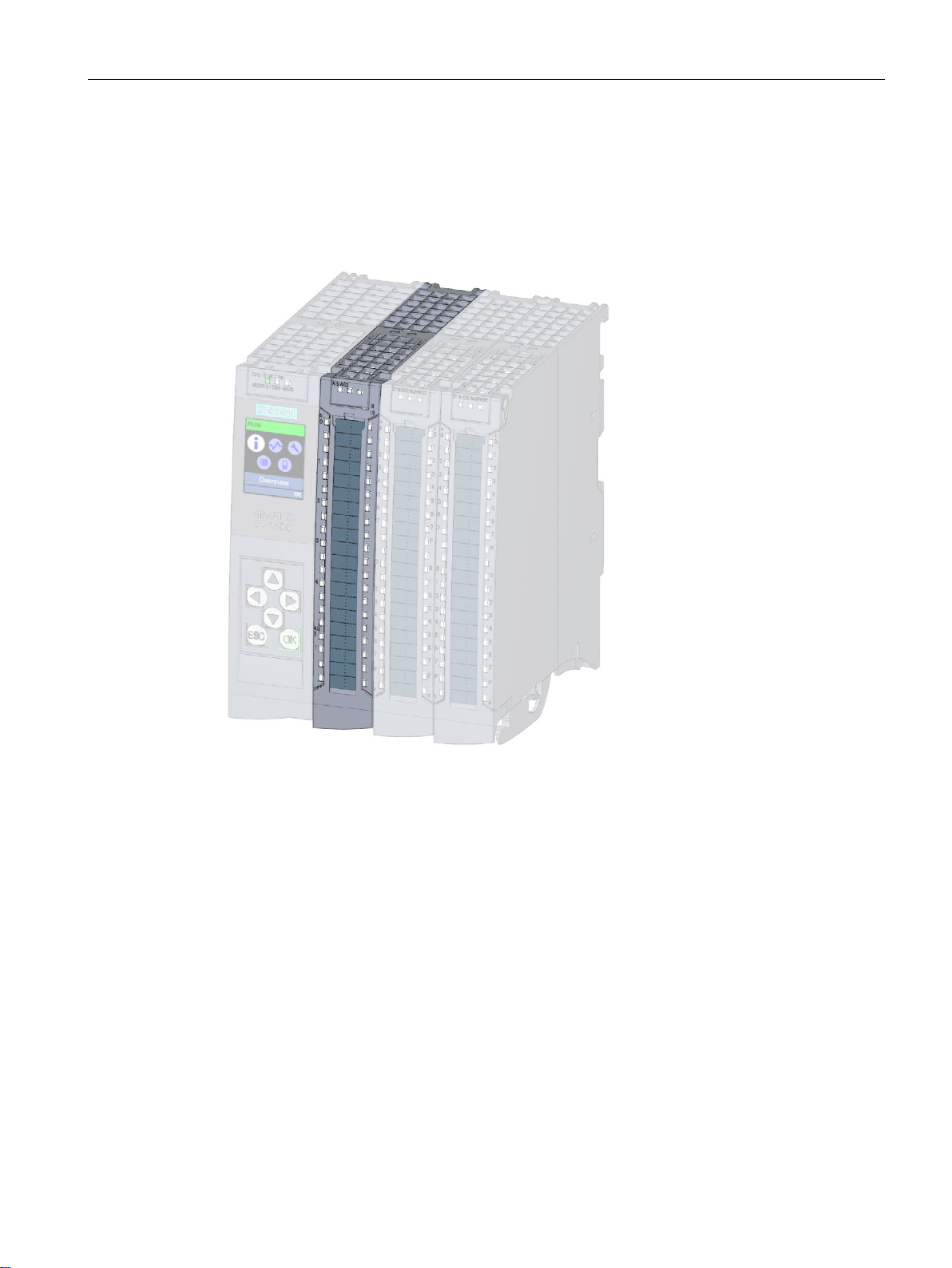
2.2 Hardware properties and firmware functions
The following figure shows the analog on-board I/O (X10) of the CPU 1512C-1 PN.
Figure 2-2 Analog on-board I/O
CPU 1512C-1 PN (6ES7512-1CK01-0AB0)
Manual, 12/2017, A5E40898741-AA
27

Product overview
Properties of the analog inputs
Property
Description
Additional information
Resolution: 16 bits including sign
analog value along this stepped curve here.
Analog value processing function
Integrated types of measuring
Configurable diagnostics
Hardware interrupt
2.2 Hardware properties and firmware functions
The 5 inputs of the analog on-board I/O module have the following properties:
You can react to process events (such as nega-
A CPU processes information exclusively in digital
format. An ADC (analog-to-digital converter) integrated
into the analog on-board I/O module therefore converts
the analog value into a bit pattern. For the CPU, this
conversion always returns a 16-bit word for SIMATIC
products. The ADC used digitalizes the analog signal
and approximates its value with a stepped curve. The
resolution specifies the number of increments of the
Controllers are only capable of processing analog values in the form of bit patterns. For this purpose, transducers which can be connected to the analog module
measure physical variables such as pressure or temperature. This analog value is measured by the analog
input module in the form of the measurement types
current, voltage or resistance. The analog on-board I/O
module supports the following measurement types on
the following channels.
• Voltage measurement type can be set individually
for channel 0 to 3
• Current measurement type can be set individually
for channel 0 to 3
• Resistor measurement type can be set for channel 4
• Thermal resistor measurement type can be set for
channel 4
The analog on-board I/O module can diagnose errors.
The module reports the diagnosed state to the CPU
using a diagnostics error interrupt. Different types of
diagnostics are available that you can parameterize
channel-granularly.
tive/positive exceeding of specific limits) through the
configuration of a hardware interrupt. Hardware interrupts can be parameterized channel-granularly.
• Chapter Analog value pro-
cessing
•
manual
(http://support.automation.sieme
ns.com/WW/view/en/67989094)
Chapter Parameters of the analog
on-board I/O (Page 122)
• Chapter Parameters of the ana-
log on-board I/O (Page 122)
• Chapter Structure of a data rec-
ord for input channels of the analog on-board I/O (Page 166)
• STEP 7 online help
CPU 1512C-1 PN (6ES7512-1CK01-0AB0)
28 Manual, 12/2017, A5E40898741-AA

Product overview
Properties of the analog outputs
Property
Description
Additional information
Resolution: 16 bits including sign
analog actuators.
Analog value processing function
Integrated output types
age". The output can be selected by individual channel.
Configurable diagnostics
channel-granularly.
2.2 Hardware properties and firmware functions
The 2 outputs of the analog on-board I/O module have the following properties:
Once the CPU has processed the digital signal, a DAC
(digital-to-analog converter) integrated in the analog onboard I/O module converts the output signal to an analog current or voltage value. The resulting value of the
output signal corresponds to the output value with
which the analog on-board I/O module controls the
With the selection of the type of output you specify
whether the digital-to-analog converter is to convert the
output signal into the type of output "Current" or "Volt-
The analog on-board I/O module can diagnose errors.
The module reports the diagnosed state to the CPU
using a diagnostics error interrupt. Different types of
diagnostics are available that you can parameterize
• Chapter Analog value pro-
cessing
•
manual
(http://support.automation.sieme
ns.com/WW/view/en/67989094)
Chapter Parameters of the analog
on-board I/O (Page 122)
CPU 1512C-1 PN (6ES7512-1CK01-0AB0)
Manual, 12/2017, A5E40898741-AA
29

Product overview
2.2.4
Firmware functions of the analog on-board I/O module
Functions of the analog inputs
Function
Description
Additional information
Reconfiguration in RUN
You have the option of reassigning parameters for the
Support of the value status
(Quality Information, QI)
Functions of the analog outputs
Function
Description
Additional information
Reconfiguration in RUN
You have the option of reassigning parameters for the
Support of the value status
(Quality Information, QI)
value output at the hardware output is incorrect.
2.2 Hardware properties and firmware functions
The 5 inputs of the analog on-board I/O module have the following functions:
analog on-board I/O module in RUN (for example,
measuring ranges of individual channels can be modified in RUN without affecting the other channels).
Value status = 1 ("Good") indicates that the value of
the assigned input at the terminal is valid.
Value status = 0 ("Bad") indicates that the read value
is not valid.
The 2 outputs of the analog on-board I/O module have the following functions:
analog on-board I/O module in RUN (for example,
output ranges of individual channels can be modified
in RUN without affecting the other channels).
Value status = 1 ("Good") indicates that the process
value specified by the user program is correctly output at the terminal.
Value status = 0 ("Bad") indicates that the process
• Chapter Parameters of the ana-
log on-board I/O (Page 122)
• Chapter Parameter assignment
and structure of the parameter
data records of the analog onboard I/O (Page 166)
Chapter Address space of the analog on-board I/O (Page 114)
• Chapter Parameters of the ana-
log on-board I/O (Page 122)
• Chapter Parameter assignment
and structure of the parameter
data records of the analog onboard I/O (Page 166)
Chapter Address space of the analog on-board I/O (Page 114)
CPU 1512C-1 PN (6ES7512-1CK01-0AB0)
30 Manual, 12/2017, A5E40898741-AA
 Loading...