

Siemens SIMATIC S7-1500, SIMATIC S7-1500R/H, SIMATIC ET 200SP, SIMATIC ET 200pro Function Manual
Page 1
Page 2

___________________
___________________
___________________
___________________
___________________
___________________
___________________
SIMATIC
S7-1500
Isochronous mode
Function Manual
10/2018
A5E43884988
Preface
Documentation guide
1
What is isochronous mode?
2
Use of isochronous mode
3
Time sequence of
synchronization
4
Configuring isochronous
mode
5
Programming isochronous
mode
6
-AA
Page 3

Siemens AG
Division Digital Factory
Postfach 48 48
90026 NÜRNBERG
GERMANY
A5E43884988-AA
Ⓟ
Copyright © Siemens AG 2018.
All rights reserved
Legal information
Warning notice system
DANGER
indicates that death or severe personal injury will result if proper precautions are not taken.
WARNING
indicates that death or severe personal injury may result if proper precautions are not taken.
CAUTION
indicates that minor personal injury can result if proper precautions are not taken.
NOTICE
indicates that property damage can result if proper precautions are not taken.
Qualified Personnel
personnel qualified
Proper use of Siemens products
WARNING
Siemens products may only be used for the applications described in the catalog and in the relevant technical
ambient conditions must be complied with. The information in the relevant documentation must be observed.
Trademarks
Disclaimer of Liability
This manual contains notices you have to observe in order to ensure your personal safety, as well as to prevent
damage to property. The notices referring to your personal safety are highlighted in the manual by a safety alert
symbol, notices referring only to property damage have no safety alert symbol. These notices shown below are
graded according to the degree of danger.
If more than one degree of danger is present, the warning notice representing the highest degree of danger will
be used. A notice warning of injury to persons with a safety alert symbol may also include a warning relating to
property damage.
The product/system described in this documentation may be operated only by
task in accordance with the relevant documentation, in particular its warning notices and safety instructions.
Qualified personnel are those who, based on their training and experience, are capable of identifying risks and
avoiding potential hazards when working with these products/systems.
Note the following:
documentation. If products and components from other manufacturers are used, these must be recommended
or approved by Siemens. Proper transport, storage, installation, assembly, commissioning, operation and
maintenance are required to ensure that the products operate safely and without any problems. The permissible
All names identified by ® are registered trademarks of Siemens AG. The remaining trademarks in this publication
may be trademarks whose use by third parties for their own purposes could violate the rights of the owner.
We have reviewed the contents of this publication to ensure consistency with the hardware and software
described. Since variance cannot be precluded entirely, we cannot guarantee full consistency. However, the
information in this publication is reviewed regularly and any necessary corrections are included in subsequent
editions.
for the specific
09/2018 Subject to change
Page 4

Preface
Purpose of the documentation
Basic knowledge required
Scope
This function manual provides an overview of the isochronous mode function for I/O modules
that you operate isochronously:
● As central I/O in a SIMATIC S7-1500
● In distributed I/O systems on PROFINET IO
● In distributed I/O systems on PROFIBUS DP
● Jointly as central and distributed I/O on PROFINET IO
The documentation supports you in the configuring and programming of isochronous mode.
The following knowledge is required in order to understand the manual:
● General knowledge of automation technology
● Knowledge of the industrial automation system SIMATIC
● Knowledge about the use of Windows-based computers
● Knowledge about how to use STEP 7 (TIA Portal)
This documentation is the basic documentation for the SIMATIC S7-1500 automation system
and all SIMATIC products from the PROFINET and PROFIBUS environments. The product
documentation is based on this documentation.
The manual applies to the SIMATIC S7-1500 automation system with CPUs Firmware
Version V2.6 or higher (except S7-1500 Compact CPUs and S7-1500R/H CPUs). SIMATIC
STEP 7 Professional V15.1 or higher is also required.
Isochronous mode
Function Manual, 10/2018, A5E43884988-AA
3
Page 5

Preface
Conventions
STEP 7:
Note
A note contains important information on the product, on handling of the product and
section of the documentation to which you should pay particular attention.
Security information
programming software "STEP 7 as of V15.1 (TIA Portal)" and subsequent versions.
This documentation contains pictures of the devices described. The figures may differ
slightly from the device supplied.
You should also pay particular attention to notes such as the one shown below:
Siemens provides products and solutions with industrial security functions that support the
secure operation of plants, systems, machines and networks.
In order to protect plants, systems, machines and networks against cyber threats, it is
necessary to implement – and continuously maintain – a holistic, state-of-the-art industrial
security concept. Siemens' products and solutions constitute one element of such a concept.
Customers are responsible for preventing unauthorized access to their plants, systems,
machines and networks. Such systems, machines and components should only be
connected to an enterprise network or the internet if and to the extent such a connection is
necessary and only when appropriate security measures (e.g. firewalls and/or network
segmentation) are in place.
We refer to "STEP 7" in this documentation as a synonym for the configuration and
on the
For additional information on industrial security measures that may be implemented, please
visit (https://www.siemens.com/industrialsecurity).
Siemens' products and solutions undergo continuous development to make them more
secure. Siemens strongly recommends that product updates are applied as soon as they are
available and that the latest product versions are used. Use of product versions that are no
longer supported, and failure to apply the latest updates may increase customers' exposure
to cyber threats.
To stay informed about product updates, subscribe to the Siemens Industrial Security RSS
Feed under (https://www.siemens.com/industrialsecurity).
Isochronous mode
4 Function Manual, 10/2018, A5E43884988-AA
Page 6

Preface
Siemens Industry Online Support
Product support
Application examples
Services
Forums
mySupport
Industry Mall
You can find current information on the following topics quickly and easily here:
●
All the information and extensive know-how on your product, technical specifications,
FAQs, certificates, downloads, and manuals.
●
Tools and examples to solve your automation tasks – as well as function blocks,
performance information and videos.
●
Information about Industry Services, Field Services, Technical Support, spare parts and
training offers.
●
For answers and solutions concerning automation technology.
●
Your personal working area in Industry Online Support for messages, support queries,
and configurable documents.
This information is provided by the Siemens Industry Online Support in the Internet
(https://support.industry.siemens.com).
The Industry Mall is the catalog and order system of Siemens AG for automation and drive
solutions on the basis of Totally Integrated Automation (TIA) and Totally Integrated Power
(TIP).
You can find catalogs for all automation and drive products on the Internet
(https://mall.industry.siemens.com).
Isochronous mode
Function Manual, 10/2018, A5E43884988-AA
5
Page 7

Table of contents
Preface ................................................................................................................................................... 3
1 Documentation guide .............................................................................................................................. 7
2 What is isochronous mode? .................................................................................................................. 12
3 Use of isochronous mode...................................................................................................................... 15
4 Time sequence of synchronization ........................................................................................................ 17
5 Configuring isochronous mode .............................................................................................................. 22
6 Programming isochronous mode ........................................................................................................... 43
Glossary ............................................................................................................................................... 49
Index .................................................................................................................................................... 54
4.1 Time sequence of synchronization on PROFINET IO and PROFIBUS DP........................... 17
4.2 Time sequence of synchronization in the central configuration ............................................. 19
5.1 Configuring isochronous mode for distributed I/O on PROFINET IO .................................... 24
5.2 Configuring isochronous mode for central I/O in S7-1500 ..................................................... 26
5.3 Configuring joint isochronous operation of central and distributed I/O .................................. 30
5.4 Configuring isochronous mode for distributed I/O on PROFIBUS DP ................................... 32
5.5 Configuring isochronous mode for a Motion Control application ........................................... 34
5.6 Setting the application cycle and delay time .......................................................................... 41
6.1 Program execution according to the IPO model .................................................................... 44
6.2 Program execution according to the OIP model .................................................................... 46
6.3 Programming of isochronous mode for Motion Control applications ..................................... 48
Isochronous mode
6 Function Manual, 10/2018, A5E43884988-AA
Page 8
1
Basic information
Device information
The documentation for the SIMATIC S7-1500 automation system, for CPU 1516pro-2 PN
based on SIMATIC S7-1500, and for the distributed I/O systems SIMATIC ET 200MP,
ET 200SP and ET 200AL is divided into three areas.
This division allows you easier access to the specific information you require.
System manuals and Getting Started manuals describe in detail the configuration,
installation, wiring and commissioning of the SIMATIC S7-1500, ET 200MP, ET 200SP and
ET 200AL systems; use the corresponding operating instructions for CPU 1516pro-2 PN.
The STEP 7 online help supports you in configuration and programming.
Product manuals contain a compact description of the module-specific information, such as
properties, terminal diagrams, characteristics and technical specifications.
Isochronous mode
Function Manual, 10/2018, A5E43884988-AA
7
Page 9

Documentation guide
General information
Manual Collections
"mySupport"
"mySupport" - Documentation
The function manuals contain detailed descriptions on general topics such as diagnostics,
communication, Motion Control, Web server, OPC UA.
You can download the documentation free of charge from the Internet
(https://support.industry.siemens.com/cs/ww/en/view/109742705).
Changes and additions to the manuals are documented in product information sheets.
You will find the product information on the Internet:
● S7-1500/ET 200MP (https://support.industry.siemens.com/cs/us/en/view/68052815)
● ET 200SP (https://support.industry.siemens.com/cs/us/en/view/73021864)
● ET 200AL (https://support.industry.siemens.com/cs/us/en/view/99494757)
The Manual Collections contain the complete documentation of the systems put together in
one file.
You will find the Manual Collections on the Internet:
● S7-1500/ET 200MP (https://support.industry.siemens.com/cs/ww/en/view/86140384)
● ET 200SP (https://support.industry.siemens.com/cs/ww/en/view/84133942)
● ET 200AL (https://support.industry.siemens.com/cs/ww/en/view/95242965)
With "mySupport", your personal workspace, you make the best out of your Industry Online
Support.
In "mySupport", you can save filters, favorites and tags, request CAx data and compile your
personal library in the Documentation area. In addition, your data is already filled out in
support requests and you can get an overview of your current requests at any time.
You must register once to use the full functionality of "mySupport".
You can find "mySupport" on the Internet (https://support.industry.siemens.com/My/ww/en).
In the Documentation area in "mySupport" you can combine entire manuals or only parts of
these to your own manual.
You can export the manual as PDF file or in a format that can be edited later.
You can find "mySupport" - Documentation on the Internet
(https://support.industry.siemens.com/My/ww/en/documentation).
Isochronous mode
8 Function Manual, 10/2018, A5E43884988-AA
Page 10

Documentation guide
"mySupport" - CAx data
Application examples
TIA Selection Tool
In the CAx data area in "mySupport", you can access the current product data for your CAx
or CAe system.
You configure your own download package with a few clicks.
In doing so you can select:
● Product images, 2D dimension drawings, 3D models, internal circuit diagrams, EPLAN
macro files
● Manuals, characteristics, operating manuals, certificates
● Product master data
You can find "mySupport" - CAx data on the Internet
(https://support.industry.siemens.com/my/ww/en/CAxOnline).
The application examples support you with various tools and examples for solving your
automation tasks. Solutions are shown in interplay with multiple components in the system separated from the focus on individual products.
You will find the application examples on the Internet
(https://support.industry.siemens.com/sc/ww/en/sc/2054).
With the TIA Selection Tool, you can select, configure and order devices for Totally
Integrated Automation (TIA).
This tool is the successor of the SIMATIC Selection Tool and combines the known
configurators for automation technology into one tool.
With the TIA Selection Tool, you can generate a complete order list from your product
selection or product configuration.
You can find the TIA Selection Tool on the Internet
(https://w3.siemens.com/mcms/topics/en/simatic/tia-selection-tool).
Isochronous mode
Function Manual, 10/2018, A5E43884988-AA
9
Page 11

Documentation guide
SIMATIC Automation Tool
PRONETA
You can use the SIMATIC Automation Tool to run commissioning and maintenance activities
simultaneously on different SIMATIC S7 stations as a bulk operation, independently of the
TIA Portal.
The SIMATIC automation tool provides a variety of functions:
● Scanning of a PROFINET/Ethernet plant network and identification of all connected CPUs
● Address assignment (IP, subnet, gateway) and station name (PROFINET device) to a
CPU
● Transfer of the date and programming device/PC time converted to UTC time to the
module
● Program download to CPU
● Operating mode switchover RUN/STOP
● CPU localization by means of LED flashing
● Reading out CPU error information
● Reading of CPU diagnostic buffer
● Reset to factory settings
● Updating the firmware of the CPU and connected modules
You can find the SIMATIC Automation Tool on the Internet
(https://support.industry.siemens.com/cs/ww/en/view/98161300).
With SIEMENS PRONETA (PROFINET network analysis), you analyze the plant network
during commissioning. PRONETA features two core functions:
● The topology overview independently scans PROFINET and all connected components.
● The IO check is a fast test of the wiring and the module configuration of a plant.
You can find SIEMENS PRONETA on the Internet
(https://support.industry.siemens.com/cs/ww/en/view/67460624).
Isochronous mode
10 Function Manual, 10/2018, A5E43884988-AA
Page 12

Documentation guide
SINETPLAN
SINETPLAN, the Siemens Network Planner, supports you in planning automation systems
and networks based on PROFINET. The tool facilitates professional and predictive
dimensioning of your PROFINET installation as early as in the planning stage. In addition,
SINETPLAN supports you during network optimization and helps you to exploit network
resources optimally and to plan reserves. This helps to prevent problems in commissioning
or failures during productive operation even in advance of a planned operation. This
increases the availability of the production plant and helps improve operational safety.
The advantages at a glance
● Network optimization thanks to port-specific calculation of the network load
● Increased production availability thanks to online scan and verification of existing systems
● Transparency before commissioning through importing and simulation of existing STEP 7
projects
● Efficiency through securing existing investments in the long term and optimal exploitation
of resources
You can find SINETPLAN on the Internet (https://www.siemens.com/sinetplan).
Isochronous mode
Function Manual, 10/2018, A5E43884988-AA
11
Page 13

2
Objectives of isochronous operation
The advantages of the isochronous mode function in automation engineering can be seen in
an example from everyday life.
The transmission of data corresponds to the transport of people on public transport.
Assuming public transport were to operate at maximum speed while reducing stop times at
the passenger terminals to absolute minimum, the last thing many potential passengers
would notice of the departing contraption are its red tail lights. The overall travel time is,
however, decided by the train, bus or underground-railway clock, because well adjusted
timing is essential to a good service. This also applies in automation engineering. Not only
fast cycles but also the coordination and synchronization of the individual cycles result in
optimum throughput.
Isochronous mode
12 Function Manual, 10/2018, A5E43884988-AA
Page 14
What is isochronous mode?
Just-In-Time
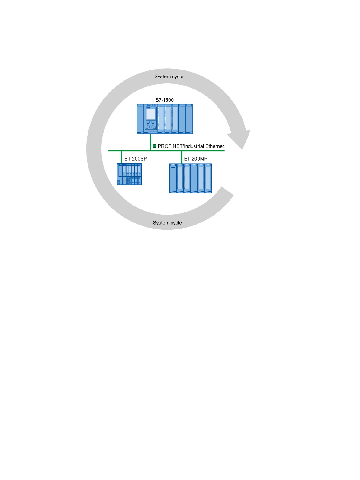
Figure 2-1 System cycle
The fast and reliable reaction time of a system operating in isochronous mode is based on
the fact that all data are provided just-in-time. The basis for this is a constant bus cycle.
The isochronous mode function guarantees synchronization of the following at constant time
intervals:
● Signal acquisition and output by the central and distributed I/O
● Signal transmission via backplane bus, PROFINET IO or PROFIBUS DP
● Program execution in the CPU in local time, in time with the constant bus cycle time
PROFINET IO or PROFIBUS DP
The result is a system that acquires its input signals, processes them and outputs the output
signals at constant time intervals. Isochronous mode guarantees precisely reproducible and
defined process reaction times as well as constant bus cycle and synchronous signal
processing for central and distributed I/O.
Isochronous mode
Function Manual, 10/2018, A5E43884988-AA
13
Page 15

What is isochronous mode?
Advantages of isochronous mode
The use of isochronous mode enables high-precision control loops.
● Optimized control loops through constant, calculable dead times
● Determinism, reliable reproducibility of reaction times
● Consistent (simultaneous) reading in of input data
● Consistent (simultaneous) output of output data
● Oversampling for processing of fast processes thanks to higher sampling rates than the
send clock permits
Isochronous mode
14 Function Manual, 10/2018, A5E43884988-AA
Page 16

3
An isochronous system acquires measured values and process data within a fixed system
cycle, processes the signals and outputs them synchronously to the process. Isochronous
mode contributes to a high control quality and increased production accuracy. With
isochronous mode, the possible fluctuations of process reaction times are drastically
reduced. You make use of the time-assured processing to improve machine cycle times.
Even fast processes can be reliably controlled thanks to the precise time reproducibility of all
sequences. Shorter cycle times increase the processing speed and help to lower production
costs.
In principle, isochronous mode lends itself to being used whenever measured values must
be acquired synchronously, movements must be coordinated, and process responses must
be defined and carried out simultaneously. There are thus numerous applications for
isochronous mode.
Isochronous mode
Function Manual, 10/2018, A5E43884988-AA
15
Page 17

Use of isochronous mode
Example: Measuring at multiple measurement points with isochronous mode
Automation task
Feature
Solution
Advantage and benefits
A camshaft production process requires precise measurement of the camshafts for quality
assurance purposes.
For this purpose, a component is needed that can synchronously measure the positions and
displacements of the cam during a rotation of the camshaft.
Figure 3-1 Measuring of camshafts
With use of isochronous mode, the measured values are simultaneously acquired at the
various measuring points at fixed times. This yields the following sequence of operations:
● Continuously rotate the camshaft
● During the continuous rotation, synchronously measure the positions and cam
displacements
● Process the next cam shaft
Thus, during a single rotation of the camshaft, all the positions of the camshaft and the
associated measured values (red) are measured synchronously. The machine cycle time
improves with the same or better measuring accuracy.
The time required for measurement is reduced.
Isochronous mode
16 Function Manual, 10/2018, A5E43884988-AA
Page 18

4
Introduction
4.1
Time sequence of synchronization on PROFINET IO and PROFIBUS DP
Introduction
The basic time sequence of all components involved in the synchronization is explained in
the following sections: The synchronization is differentiated according to distributed
configuration and central configuration in an S7-1500. You can combine isochronous I/O with
non-isochronous I/O in the configuration.
You can operate I/O modules in distributed I/O systems isochronously on a CPU:
● On PROFINET IO, e.g. in distributed I/O systems ET 200SP, ET 200MP
● On PROFIBUS DP, e.g. in distributed I/O systems ET 200S, ET 200M.
Like the I/O modules, the interface modules of the I/O systems must support isochronous
mode.
Isochronous mode
Function Manual, 10/2018, A5E43884988-AA
17
Page 19

Time sequence of synchronization
From reading-in of input data to outputting of output data
T_DC
Data cycle (Time_DataCycle)
TI
Time for reading in the input data
TO
Time for outputting the output data
TV
Configured delay time
4.1 Time sequence of synchronization on PROFINET IO and PROFIBUS DP
The basic time sequence of all components involved in synchronization is explained in the
following:
① Measured value acquisition in the process
② Isochronous read-in of input data
③ Transport of input data to the IO controller/DP master (CPU) via the subnet
④ Further processing in the isochronous application of the CPU
⑤ Transport of output data to the outputting IO device/DP slave via the subnet
⑥ Isochronous output of output data
Figure 4-1 Time sequence of synchronization on PROFINET IO/PROFIBUS DP
So that all input data is ready for transport via the subnet at the next start of the
PROFINET IO-/PROFIBUS DP cycle, the start of the I/O read-in cycle is advanced by the
amount of lead time T
at this time. T
is necessary in order to compensate for analog-to-digital conversion,
I
backplane bus times and the like. The lead time T
Let the lead time T
ensures that a common, minimum T
Isochronous mode
. TI is the "flashbulb" for the inputs. All synchronized inputs are read in
I
can be configured by STEP 7 or by you.
I
be assigned automatically by STEP 7. With the default setting, STEP 7
I
is set.
I
18 Function Manual, 10/2018, A5E43884988-AA
Page 20

Time sequence of synchronization
4.2
Time sequence of synchronization in the central configuration
Introduction
not
4.2 Time sequence of synchronization in the central configuration
The subnet transports the input data to the IO controller/DP master. The application is
started synchronized to the cycle. That is, the isochronous mode interrupt OB is called after
a configurable delay time T
. The user program in the isochronous mode interrupt OB
V
defines the process response and provides the output data in time for the start of the next
data cycle. The length of the data cycle (send clock/DP cycle time) is always configured by
you.
is the time for the compensation arising from the backplane bus and the digital-to-analog
T
O
is the "flashbulb" for the outputs. The
O
can be configured by STEP 7 or by
O
conversion within the IO device/DP slave. T
synchronized outputs are output at this time. Time T
you. Let time T
common, minimum T
be assigned automatically by STEP 7. STEP 7 automatically calculates a
O
.
O
You can operate I/O modules isochronously downstream of an S7-1500 CPU starting with
Firmware Version 2.6.
Exception: Isochronous operation of I/O modules in the central configuration is generally
possible:
● With compact CPUs of S7-1500
● With CPUs of S7-1500R/H
● With PROFINET IO and PROFIBUS DP systems on centrally configured communications
processors (CPs) or communication modules (CMs)
● With communications processors (CPs) or communication modules (CMs) as I-devices or
I-slaves in the central configuration
When using isochronous I/O in the central configuration, you cannot make use of the
configuration control (option handling) function.
Isochronous mode
Function Manual, 10/2018, A5E43884988-AA
19
Page 21

Time sequence of synchronization
From reading-in of input data to outputting of output data
T_DC
Data cycle (Time_DataCycle)
TI
Time for reading in the input data
TO
Time for outputting the output data
TV
Configured delay time
4.2 Time sequence of synchronization in the central configuration
The basic time sequence of all components involved in synchronization is explained in the
following:
① Measured value acquisition in the process
② Isochronous read-in of input data from the central I/O
③ Transport of input data to the CPU
④ Further processing in the isochronous application of the CPU
⑤ Transport of output data to the central I/O
⑥ Isochronous output of output data
Figure 4-2 Time sequence of synchronization in the central configuration
So that all input data is ready for transport to the CPU at the next start of the cycle, the start
of the I/O read-in cycle is advanced by the amount of lead time T
inputs. After that, all synchronized inputs are read in. T
is necessary in order to compensate
I
for analog-to-digital conversion and the like. The lead time T
or by you. Let the lead time T
STEP 7 ensures that a common, minimum T
Isochronous mode
be assigned automatically by STEP 7. With the default setting,
I
is set.
I
. TI is the "flashbulb" for the
I
can be configured by STEP 7
I
20 Function Manual, 10/2018, A5E43884988-AA
Page 22

Time sequence of synchronization
4.2 Time sequence of synchronization in the central configuration
The backplane bus transports the input data to the CPU. The application is started
synchronized to the cycle. That is, the isochronous mode interrupt OB is called after a
configurable delay time T
. The user program in the isochronous mode interrupt OB defines
V
the process response and provides the output data in time for the start of the next data cycle.
The length of the data cycle (send clock) is always configured by you.
Within time T
, the data is:
O
● Transported to the I/O module over the backplane bus
● Processed in the I/O module, e.g. converted to an analog value
After expiration of time T
Time T
can be configured by STEP 7 or by you. Let time TO be assigned automatically by
O
STEP 7. STEP 7 automatically calculates a common, minimum T
, the data is output to the process.
O
O
.
Isochronous mode
Function Manual, 10/2018, A5E43884988-AA
21
Page 23

5
Configuring at a glance
Setting parameters for isochronous operation of the I/O module
Setting the send clock or DP cycle time
Setting the application cycle
You can operate I/O modules isochronously both as central I/O in SIMATIC S7-1500 and as
distributed I/O in a distributed I/O system.
You can also jointly operate central and distributed I/O on PROFINET IO isochronously.
The following sections describe the procedure for configuring this using examples.
You use the properties of the I/O addresses of the corresponding I/O module to:
● Set isochronous mode for the module
● Assign the inputs and outputs of the module to a process image partition and an
isochronous mode interrupt OB
The data of the process image partition is updated synchronously to the assigned OB.
Isochronous mode interrupts give you the option of starting programs isochronously with
the backplane bus, with the PROFIBUS DP cycle or PROFINET send clock. Isochronous
mode interrupts are processed with high priority.
The send clock/DP cycle time is the shortest possible transmission interval for the data
exchange. In isochronous mode, the send clock/DP cycle time corresponds to data cycle
T_DC.
For distributed I/O in S7-1500, you set the send clock in the properties of the CPU. For
PROFINET IO, you set the send clock in the properties of the PROFINET interface of the
CPU or in the sync domain. For PROFIBUS DP, you set the DP cycle time in the properties
of the DP master system.
The application cycle is a multiple of data cycle T_DC. If the runtime of the isochronous
mode interrupt OB is short, the application cycle can be identical to the data cycle (= send
clock/DP cycle time).
You can reduce the application cycle of the isochronous mode interrupt OB relative to the
send clock of an isochronous system. Set an integer multiple of the send clock as the
reducing factor.
You use the factor to reduce the CPU utilization by executing the isochronous mode interrupt
OB less frequently. You set the application cycle in the properties of the isochronous mode
interrupt OB.
You can find more information in the section Programming isochronous mode (Page 43).
Isochronous mode
22 Function Manual, 10/2018, A5E43884988-AA
Page 24

Configuring isochronous mode
Setting the delay time
Additional configurations for isochronous mode on PROFINET IO:
Setting IRT as the RT class for the interconnected PROFINET interfaces
Configuring the topology of the configuration
Using a sync domain
The delay time is the time between the start of the send clock and the start of the
isochronous mode interrupt OB. During this time, the IO controller/DP master performs the
cyclic data exchange with the IO devices/DP slaves.
STEP 7 sets the default delay time in such a way that the isochronous update of the process
image partition automatically falls within the execution window of the application cycle.
You set the delay time in the properties of the isochronous mode interrupt OB. A shorter
delay time enables you to increase the processing time for your user program in the
isochronous mode interrupt OB.
●
A precondition for isochronous operation on PROFINET IO is IRT communication
(Isochronous Real Time Communication). IRT means synchronized data exchange at
reserved time intervals.
●
A precondition for IRT communication is the topology configuration. In addition to the
reserved bandwidth, the exchange of frames on defined transmission paths is used for
further optimization of data communication. For this, the topological information of the
configuration is used for planning the communication.
●
you assign the IO devices (sync slaves) to an IO controller (sync
master) for the isochronous data exchange.
A precondition for IRT communication is a synchronization cycle for all PROFINET
devices in a sync domain, for distribution of a common time base. With this base
synchronization, a synchronous operation of the transmission cycle of the PROFINET
devices within a sync domain is achieved.
Isochronous mode
Function Manual, 10/2018, A5E43884988-AA
23
Page 25

Configuring isochronous mode
5.1
Configuring isochronous mode for distributed I/O on PROFINET IO
Introduction
Requirements
5.1 Configuring isochronous mode for distributed I/O on PROFINET IO
The configuring of isochronous mode for a module is described in the following for an IO
device based on the ET 200MP distributed I/O system. The procedure described also
applies to other distributed I/O systems (e.g., ET 200S or ET 200SP).
The IO controller is an S7-1500 CPU.
● The network view of STEP 7 is open.
● An S7-1500 CPU has been placed (e.g. CPU 1516-3 PN/DP).
● An IM 155-5 PN HF interface module (ET 200MP) has been placed and networked with
the CPU via PROFINET IO.
● All requirements for an IRT configuration are met:
– The ports of the networked PROFINET interfaces of the CPU and interface module
are interconnected (topology configuration).
– The RT class of the PROFINET interface of the interface module is set to "IRT" (area
"Advanced options > Real time settings > Synchronization").
– The "sync master" and "sync slave" roles are assigned for the PROFINET interfaces
of the CPU and interface module (in the properties of a PROFINET interface: area
"Advanced options" > "Real time settings" > "Synchronization").
Isochronous mode
24 Function Manual, 10/2018, A5E43884988-AA
Page 26

Configuring isochronous mode
Procedure
5.1 Configuring isochronous mode for distributed I/O on PROFINET IO
To create an isochronous connection between the I/O and user program, follow these steps:
1. Select the "IM 155-5 PN HF" in the network view of STEP 7. Change to the device view.
2. Insert an I/O module that can be operated isochronously (e.g. DI 16 x 24VDC HF).
3. Go to the "I/O addresses" area in the Inspector window of the selected I/O module.
Figure 5-1 Configuring isochronous mode on PROFINET IO
4. Make the following settings in the I/O addresses area:
– Select the "Isochronous mode" option.
– Select a process image partition, e.g., process image partition 1.
– Click the "Organization block" drop-down list. Click the "Add" button or select an
already existing OB. A dialog box for selecting organization blocks opens.
– Select the "Synchronous Cycle" OB. Confirm the selection with "OK".
In the case of automatic number assignment, OB 61 will be generated and opened.
In the Inspector window, you can continue directly with the setting of the application
cycle and delay time (Page 41) in the "Isochronous mode" area and start the
programming of the OB in the instruction section.
Isochronous mode
Function Manual, 10/2018, A5E43884988-AA
25
Page 27

Configuring isochronous mode
Reference
5.2
Configuring isochronous mode for central I/O in S7-1500
Introduction
Requirements
5.2 Configuring isochronous mode for central I/O in S7-1500
5. If required, add additional I/O modules in the central configuration and IO devices in the
hardware configuration. Adapt the configuration and the settings for the isochronous
mode.
6. You want to retrieve information about calculated bandwidths or for adapting the send
clock. Select the PROFINET interface in the network view and navigate to the area
"Advanced options" > "Real time settings" > "Synchronization" > "Domain settings".
You can find more information on PROFINET functions, such as IRT, in the PROFINET
(http://support.automation.siemens.com/WW/view/en/49948856) function manual.
You can find examples of parameter assignment and possible settings of isochronous mode
for distributed I/O and drives in STEP 7 as FAQs on the Internet
(https://support.industry.siemens.com/cs/ww/en/view/109480489).
The configuring of isochronous mode for a module is described in the following based on an
analog input module in S7-1500. The procedure is also valid for other I/O modules that
support isochronous mode.
● The network view of STEP 7 is open.
● An S7-1500 CPU has been placed (e.g. CPU 1516-3 PN/DP).
Isochronous mode
26 Function Manual, 10/2018, A5E43884988-AA
Page 28

Configuring isochronous mode
Procedure
5.2 Configuring isochronous mode for central I/O in S7-1500
To create an isochronous connection between the I/O and user program, follow these steps:
1. Select the CPU 1516-3 PN/DP in the network view of STEP 7. Change to the device
view.
2. Insert an I/O module that can be operated isochronously (e.g. AI 8 x U/I HS).
3. Go to the "I/O addresses" area in the Inspector window of the selected I/O module.
Figure 5-2 Configuring isochronous mode centrally on the AI module
Isochronous mode
Function Manual, 10/2018, A5E43884988-AA
27
Page 29

Configuring isochronous mode
5.2 Configuring isochronous mode for central I/O in S7-1500
4. Make the following settings in the I/O addresses area:
– Select the "Isochronous mode" option.
– Select a process image partition, e.g., process image partition 1.
– Click on the "Organization block" drop-down list and click the "Add new" button or
select an already existing OB. A dialog box for selecting organization blocks opens.
– Select the "Synchronous Cycle" OB. Confirm the selection with "OK".
In the case of automatic number assignment, OB 61 will be generated and opened.
The "Isochronous mode" area is selected in the Inspector window, and you can
continue directly with the setting of the application cycle and delay time (Page 41) and
start the programming of the OB in the instruction section.
5. If, due to the utilized modules, the isochronous system only operates with a certain send
clock (e.g. 1 ms) but the process values must be sampled faster, use the oversampling
function. In the example, you minimize the send clock into 4 sub-clocks using the
sampling rate. In this way you sample the process values for the channels of the analog
input module every 250 µs.
In the properties of the analog input module in the "Module parameters" > "AI
configuration" area, set a sampling rate of 4 samples per cycle under "Oversampling".
Figure 5-3 Configuring oversampling on the AI module
6. If required, insert additional I/O modules in the device view. Adapt the configuration and
the settings for isochronous mode.
7. Select the CPU 1516-3 PN/DP in the device view of STEP 7 in order to check the settings
for isochronous mode.
8. Navigate to the "Isochronous mode" area in the Inspector window of the selected CPU
Isochronous mode
28 Function Manual, 10/2018, A5E43884988-AA
Page 30

Configuring isochronous mode
5.2 Configuring isochronous mode for central I/O in S7-1500
9. In the "Isochronous mode for local modules" area, check to determine if:
– Isochronous mode is selected
– "Local send clock" is selected as the synchronization type
If necessary, you can adapt the send clock and times T
for the isochronous read-
i/To
in/output of data.
10.In the "Detail overview" area, you see all modules of the configuration you can operate
isochronously. Select or deselect isochronous mode for the desired modules as
appropriate.
Figure 5-4 Configuring isochronous mode centrally on the CPU
Isochronous mode
Function Manual, 10/2018, A5E43884988-AA
29
Page 31

Configuring isochronous mode
5.3
Configuring joint isochronous operation of central and distributed I/O
Introduction
Setting the same send clock for central and distributed I/O
Requirements
5.3 Configuring joint isochronous operation of central and distributed I/O
You can jointly operate central I/O in S7-1500 and distributed I/O on PROFINET IO
isochronously.
For the coordination and synchronization of the processing cycles of the central and
distributed I/O, you set the same send clock and isochronous mode interrupt OB in STEP 7.
The system clock results from the values for the central and distributed configurations.
Foremost here is the PROFINET send clock to which the central configuration is
synchronized. If necessary, you must set a higher send clock for PROFINET IO, which takes
the overall system into account.
You want to operate modules configured as central I/O in S7-1500 and modules configured
as distributed I/O in ET 200MP isochronously with the same send clock.
● You have connected distributed I/O in an ET 200MP as isochronous I/O to PROFINET IO
(see section Configuring isochronous mode for distributed I/O on PROFINET IO
(Page 24)).
● The IO controller is an S7-1500 CPU.
● You have connected central I/O of the S7-1500 as isochronous I/O (see section
Configuring isochronous mode for central I/O in S7-1500 (Page 26)).
● You have configured the same isochronous mode interrupt OB and the same process
image partition for central and distributed I/O.
Isochronous mode
30 Function Manual, 10/2018, A5E43884988-AA
Page 32

Configuring isochronous mode
Procedure
Result:
Isochronous mode interrupt OB and process image partition
Note
Ensure that you have configured the same isochronous
process image partition for the central and distributed I/O you want to jointly operate
isochronously.
5.3 Configuring joint isochronous operation of central and distributed I/O
1. Navigate to the "Isochronous mode" area in the properties of the CPU.
2. In the "Isochronous mode for local modules" area, use "Use send clock of PROFINET
interface [X1]" in the "Synchronization type" drop-down list.
Figure 5-5 Setting the same send clock for central and distributed I/O
The modules in the central configuration have adopted the send clock and the TI/TO
values from the PROFINET interface X1.
For joint isochronous operation of central and distributed I/O in a project, the following
condition must be met:
mode interrupt OB and the same
Isochronous mode
Function Manual, 10/2018, A5E43884988-AA
31
Page 33

Configuring isochronous mode
5.4
Configuring isochronous mode for distributed I/O on PROFIBUS DP
Introduction
Requirements
5.4 Configuring isochronous mode for distributed I/O on PROFIBUS DP
The configuring of isochronous mode is described in the following for a DP slave based on
the ET 200S distributed I/O system. The procedure described also applies to other
distributed I/O systems, e.g. for ET 200M.
The IO controller is an S7-1500 CPU.
● The network view of STEP 7 is open.
● A CPU has been placed (e.g., CPU 1516-3 PN/DP).
● An interface module which supports isochronous mode has been placed and networked
with the CPU (e.g., IM 151-1 HF).
● I/O modules have been placed (e.g. 2DI x DC24V HF and 2DO x DC24V/0,5A HF).
● Only the constant bus cycle time master is permitted as active station on the isochronous
PROFIBUS DP.
● Assignment of a SYNC/FREEZE group to the DP slave is not permitted.
Isochronous mode
32 Function Manual, 10/2018, A5E43884988-AA
Page 34

Configuring isochronous mode
Procedure for configuring isochronous mode on the DP slave
Procedure for configuring the I/O module
5.4 Configuring isochronous mode for distributed I/O on PROFIBUS DP
1. Select the DP slave in the network view. Navigate to the "Isochronous mode" area in the
Inspector window.
2. Enable the option for synchronization to the DP cycle for the DP slave.
Default: The DP slaves get the Ti/To values from the subnet. Therefore, the values are
automatically the same for all DP slaves of the DP master system.
3. In the "Detail overview", select the "Isochronous mode" option for all I/O modules you
want to operate isochronously.
4. Repeat steps 1 and 3 for all DP slaves that you want to operate in isochronous mode.
Figure 5-6 Configuring isochronous mode on the DP slave
1. Select an I/O module in the device view. Navigate to the "I/O addresses" area in the
Inspector window.
– The option for isochronous mode is selected.
Assign the process image partition and OB to the I/O modules as described in section
Configuring isochronous mode for distributed I/O on PROFINET IO (Page 24).
Isochronous mode
Function Manual, 10/2018, A5E43884988-AA
33
Page 35

Configuring isochronous mode
5.5
Configuring isochronous mode for a Motion Control application
Introduction
Requirements
Procedure for configuring isochronous mode for a drive
5.5 Configuring isochronous mode for a Motion Control application
The configuring of isochronous mode for a Motion Control application with cam output is
described in the following.
You connect a SINAMICS V90 drive with a positioning axis to an S7-1500 CPU as
isochronous distributed I/O.
The drive is controlled using the CPU-internal Motion Control functions.
You connect the cam output to the CPU as an isochronous cam output using technology
module TM Timer DIDQ 16 x 24V.
● The network view of STEP 7 is open.
● An S7-1500 CPU has been placed (e.g. CPU 1516-3 PN/DP).
For isochronous operation of a drive, you configure the drive frame as an isochronous frame.
So that the CPU can control the drive, you then assign the drive to a Motion Control
technology object of the CPU.
Follow these configuration steps:
1. Insert a SINAMICS V90 drive from the hardware catalog in the network view (Additional
Field Devices > PROFINET IO > Drives > SIEMENS AG > SINAMICS > SINAMICS V90
PN).
2. Connect the PROFINET interface of the V90 to the PROFINET interface X1 of the CPU in
the network view.
3. Change to the topology view. Interconnect the corresponding ports of the PROFINET
interfaces of the devices.
4. Select the V90 and change to the device view.
5. In the properties of the V90, navigate via General > PROFINET interface > Advanced
options to the "Isochronous mode" area.
6. Select the "Isochronous mode" option.
Isochronous mode
34 Function Manual, 10/2018, A5E43884988-AA
Page 36

Configuring isochronous mode
5.5 Configuring isochronous mode for a Motion Control application
7. In the hardware catalog, double-click on Standard Frame 3, ...
Figure 5-7 Assigning Standard Frame 3 to the V90
Isochronous mode
Function Manual, 10/2018, A5E43884988-AA
35
Page 37

Configuring isochronous mode
5.5 Configuring isochronous mode for a Motion Control application
8. In the properties of the V90, select the "Isochronous mode" option for Standard Frame 3
in the detail overview.
Figure 5-8 Assigning isochronous mode to Standard Frame 3
Isochronous mode
36 Function Manual, 10/2018, A5E43884988-AA
Page 38

Configuring isochronous mode
5.5 Configuring isochronous mode for a Motion Control application
9. In the project tree, navigate in the folder of the CPU to "Technology objects".
10.Insert a "Positioning axis" technology object.
Figure 5-9 Creating a positioning axis technology object
Isochronous mode
Function Manual, 10/2018, A5E43884988-AA
37
Page 39

Configuring isochronous mode
Results:
5.5 Configuring isochronous mode for a Motion Control application
11.Assign the drive V90 to the positioning axis.
Figure 5-10 Assigning the drive to the positioning axis
– As soon as an axis was created for the CPU, the MC Servo OB is automatically
created and set synchronous to the PROFINET IO.
– The drive is automatically assigned to the MC Servo OB and the TPA OB Servo
process image partition when the axis is created.
– The drive is connected as an isochronous drive.
Isochronous mode
38 Function Manual, 10/2018, A5E43884988-AA
Page 40

Configuring isochronous mode
Procedure for configuring isochronous mode for a cam controller using a Timer technology module
5.5 Configuring isochronous mode for a Motion Control application
For isochronous operation of a cam controller on a CPU, you configure a TM Timer
technology module as an isochronous technology module. So that the CPU can control an
output cam of the axis isochronously, you assign an output cam to the TM Timer technology
module.
Follow these configuration steps:
1. Switch to the device view of the CPU.
2. Select technology module TM Timer DIDQ 16 x 24V from the hardware catalog. Place the
technology module in a slot to the right of the CPU.
3. The channel configuration "0 inputs, 16 outputs" and operating mode "Timer DQ" are
preset in the properties of the technology module for the individual outputs.
4. In the properties of the technology module, "I/O addresses", select the "Isochronous
mode" option.
5. Set the same send clock for central and distributed I/O. You can find more information in
the section Configuring joint isochronous operation of central and distributed I/O
(Page 30).
6. In the project tree for the positioning axis, add a new output cam under "Output cams".
Figure 5-11 Assigning the output cam to the positioning axis
Isochronous mode
Function Manual, 10/2018, A5E43884988-AA
39
Page 41

Configuring isochronous mode
Result
Reference
5.5 Configuring isochronous mode for a Motion Control application
7. In the "Output cam output" area of the configuration, enable output by the technology
module for the output cam. Assign a cam output.
Figure 5-12 Assigning output of the technology module to the output cam
The addresses and TPA OB Servo process image partition are automatically assigned to
the technology module.
: The cam output is configured as isochronous cam output.
You can find information on programming isochronous mode for Motion Control applications
in section Programming isochronous mode.
You can find additional information on the above-mentioned OBs and their use in the
STEP 7 online help.
You can find examples of parameter assignment and possible settings of isochronous mode
for distributed I/O and drives in STEP 7 as FAQs on the Internet
(https://support.industry.siemens.com/cs/ww/en/view/109480489).
Isochronous mode
40 Function Manual, 10/2018, A5E43884988-AA
Page 42

Configuring isochronous mode
5.6
Setting the application cycle and delay time
Requirements
Setting the application cycle
5.6 Setting the application cycle and delay time
● You have created an isochronous mode configuration in STEP 7.
● You have created an isochronous mode interrupt OB Synchronous Cycle (OB 6x).
● The isochronous mode interrupt OB is open.
The application cycle is a multiple of data cycle T_DC (send clock). You use the application
cycle setting to reduce the CPU utilization caused by execution of the isochronous mode
interrupt OB. In the following example, the OB is called only after every 2nd data cycle T_DC
in the CPU.
To set the application cycle for your isochronous mode application, follow these steps:
1. Open the "Properties" dialog of the isochronous mode interrupt OB under consideration.
2. In the area navigation, click the "Isochronous mode" group .
3. Set the application cycle in "Application cycle (ms)". Open the drop-down list box and
select the application cycle. The drop-down list offers multiples of data cycle T_DC as
possible values for the application cycle. Data cycle T_DC is set to 2 ms in the following
figure.
Figure 5-13 Setting the application cycle
Isochronous mode
Function Manual, 10/2018, A5E43884988-AA
41
Page 43

Configuring isochronous mode
Setting the delay time
5.6 Setting the application cycle and delay time
The delay time is the time between the start of the send clock and the start of the
isochronous mode interrupt OB. STEP 7 sets the delay time automatically to the start of the
execution window by default. As a result, the isochronous mode update of the process image
partition automatically falls within the execution window of the application cycle. Note that
you must call the "SYNC_PI" and "SYNC_PO" instructions in the execution window of the
application cycle.
You can also set the delay time manually. A shorter delay time enables you to increase the
processing time for your user program in the isochronous mode interrupt OB.
To set the delay time for your isochronous mode application, follow these steps:
1. Open the "Properties" dialog of the isochronous mode interrupt OB under consideration.
2. In the area navigation, click the "Isochronous mode" group .
3. Clear the "Automatic setting" check box.
4. Enter your desired delay time in "Delay time (ms)".
Figure 5-14 Setting the delay time
Isochronous mode
42 Function Manual, 10/2018, A5E43884988-AA
Page 44

6
Programming in the isochronous mode interrupt OBs
Access to isochronous I/O through call of instructions
Note
Recommendation: To prevent inconsistent data from being returned to OB 6x, do not use the
"DPRD_DAT" and "DPWR_DAT" instructions (direct data access) in the isochronous mode
interrupt OB.
Program execution models
IPO
OIP
You program the isochronous section of the program exclusively in the isochronous mode
interrupt OBs Synchronous Cycle (OB 6x) and, for Motion Control applications, in the
OBs MC-PreServo and MC-PostServo.
The isochronous mode interrupt OBs Synchronous Cycle (OB 6x) apply to the isochronous
operation of modules centrally in S7-1500 and in the assigned distributed I/O systems.
Because the isochronous mode interrupts are processed with high priority, only the timecritical sections of the program should be processed in the isochronous mode interrupt OB.
The isochronous mode interrupt is called with a configured delay time.
You access the isochronous I/O via a process image partition. That is, the addresses of the
isochronous modules must be within one process image partition.
The CPU updates the process image partitions of the isochronous I/O in the central and
distributed configurations by calling the instructions SYNC_PI and SYNC_PO .
These instructions are not necessary for Motion Control applications. OB MC-Servo
automatically updates the process image partitions.
The "SYNC_PI" and "SYNC_PO" instructions update the process image partition only within
the permitted execution window. The execution window stretches from the end of the cyclical
data exchange to the point in time before the end of T_DC at which the outputs can still be
copied in time. The data exchange must be started within this time window. If the execution
window is violated by the processing of the "SYNC_PI" and "SYNC_PO" instructions, the
instructions indicate a corresponding error message.
Depending on your requirements regarding reaction time and execution time of the
isochronous mode interrupt OB, there are two basic models for processing the program:
●
model (read Inputs - Processing - write Outputs)
●
model (write Outputs - read Inputs - Processing)
You implement the respective model through the different call sequence of SYNC_PI and
SYNC_PO in the user program.
Isochronous mode
Function Manual, 10/2018, A5E43884988-AA
43
Page 45

Programming isochronous mode
6.1
Program execution according to the IPO model
Programming according to the IPO model in the isochronous mode interrupt OB
Step
Action
Explanation
partition and provides them to the isochronous mode interrupt OB.
program via the process image partition.
6.1 Program execution according to the IPO model
If the execution time of the isochronous mode interrupt OB is significantly shorter than one
data cycle T_DC, use the IPO model. In the IPO model, you do not reduce the data cycle.
That is, the application cycle of the isochronous mode interrupt OB is equal to data cycle
T_DC.
The IPO model enables the shortest reaction times.
For programming according to the IPO model:
1. Call the SYNC_PI instruction at the start of the isochronous mode interrupt OB.
2. Then, call the actual user program.
3. Call the "SYNC_PO" instruction at the end of the isochronous mode interrupt OB.
Table 6- 1 Sequence according to the IPO model
1 Read in (I) The SYNC_PI instruction reads in the inputs of the process image
2 Process (P) The user program in the isochronous mode interrupt OB is executed.
3 Output (O) The SYNC_PO instruction outputs the data changed by the user
Isochronous mode
44 Function Manual, 10/2018, A5E43884988-AA
Page 46

Programming isochronous mode
Signal sequence in the IPO model
①
Execution of isochronous mode interrupt OB
②
"SYNC_PI" instruction
③
"SYNC_PO" instruction
④
Isochronous read-in of process values on I/O module at time TI
⑤
Isochronous output of process values on I/O module at time TO
6.1 Program execution according to the IPO model
The following figure shows the signal sequence in the IPO model from the acquisition and
the processing in the CPU to the output of the process values:
Figure 6-1 Signal sequence in the IPO model
At time TI the process values are read in isochronously on the I/O. The processing of the
data in the IPO model is completed within one data cycle T_DC. The output data is always
available on the I/O in the next data cycle T_DC at time T
.
O
With the IPO model, there is a constant execution time from the "input terminal" to the
"output terminal" of T
T
+ 2×T_DC + TO can be guaranteed for the process response time for asynchronous
I
+ T_DC + TO.
I
events.
Isochronous mode
Function Manual, 10/2018, A5E43884988-AA
45
Page 47

Programming isochronous mode
6.2
Program execution according to the OIP model
Programming according to the OIP model in the isochronous mode interrupt OB
Step
Action
Explanation
image partition.
nous mode interrupt OB.
3
Process (P)
The user program in the isochronous mode interrupt OB is executed.
6.2 Program execution according to the OIP model
Use the OIP model in the case of execution cycles of the isochronous mode interrupt OB of
different lengths, if the application cycle is greater than data cycle T_DC.
The data exchange with the process is always deterministic also in the OIP model, which
means it takes place at a precisely specified time.
For programming according to the OIP model:
1. Call the SYNC_PO instruction at the start of the isochronous mode interrupt OB.
2. Then call the SYNC_PI instruction:
3. Then, call the actual user program.
Table 6- 2 Sequence according to the OIP model
1 Output (O) The SYNC_PO instruction outputs the data that was changed by the
user program in the previous cycle via the outputs of the process
2 Read in (I) The SYNC_PI instruction reads in the inputs of the process image
partition of the current cycle and provides the inputs to the isochro-
Isochronous mode
46 Function Manual, 10/2018, A5E43884988-AA
Page 48

Programming isochronous mode
Signal sequence in the OIP model
①
Execution of isochronous mode interrupt OB
②
"SYNC_PI" instruction
③
"SYNC_PO" instruction
④
Isochronous read-in of process values on I/O module at time TI
⑤
Isochronous output of process values on I/O module at time TO
6.2 Program execution according to the OIP model
The following figure shows the signal sequence in the OIP model from the acquisition of
process values and the processing in the CPU to the output of the process values: The
application cycle is twice as long as data cycle T_DC in this example.
Figure 6-2 Signal sequence in the OIP model
At time TI the process values are read in isochronously on the I/O. The data is processed
over 2 application cycles in the OIP model. The output data is always available on the I/O in
the following application cycle at time T_DC + T
With the IPO model, there is a constant execution time from the "input terminal" to the
"output terminal" of T
T
+ 2 x application cycle + T_DC + TO can be ensured as the process reaction time.
I
+ application cycle + T_DC + TO.
I
.
O
Isochronous mode
Function Manual, 10/2018, A5E43884988-AA
47
Page 49

Programming isochronous mode
6.3
Programming of isochronous mode for Motion Control applications
MC-Servo, MC-PreServo and MC-PostServo OBs
Note
The reduction ratio of the MC
technology object.
Inte
is set too high.
Reference
6.3 Programming of isochronous mode for Motion Control applications
The CPU-internal Motion Control functions are to control a drive. When an axis is created in
the CPU, the MC Servo OB is automatically created in the user program. This OB contains
an automatic update of the process image partitions.
If user programs are to be processed synchronized to the MC-Servo OB, integrate the user
programs in the MC PreServo or MC PostServo OBs. The SNYC_PI and SYNC_PO
instructions are not necessary.
The process image partitions are always updated as follows:
● The inputs are read prior to processing the MC-PreServo OB.
● The outputs are output after processing the MC-PostServo OB.
The runtime of the MC Servo OB must never be longer than the send clock of the
isochronous PROFINET IO system. When the runtime of the MC-Servo OB reaches the
length of the send clock, you must:
● reduce the application cycle in the properties of the MC-Servo OB
and
● extend the send clock in the properties of the PROFINET interface of the CPU
-Servo OB also influences the axis control of the Axis
rferences at the axis may not be compensated for satisfactorily by a reduction ratio that
You can find additional information on the above-mentioned OBs and their use in the
STEP 7 online help.
You can find examples of parameter assignment and possible settings of isochronous mode
for distributed I/O and drives in STEP 7 as FAQs on the Internet
(https://support.industry.siemens.com/cs/ww/en/view/109480489).
Isochronous mode
48 Function Manual, 10/2018, A5E43884988-AA
Page 50

Glossary
Analog-to-digital conversion
Application, isochronous
Automation system
Backplane bus
Bus
CPU
C
Delay time
Determinism
Conversion of analog input signals into digital signals for processing in the CPU.
User program in the isochronous mode interrupt OB. The user program in the isochronous
mode interrupt OB ensures the isochronous and consistent updating of the assigned process
image participation.
Programmable logic controller for the open-loop and closed-loop control of process chains in
process and production engineering. The automation system consists of different
components and integrated system functions depending on the automation task.
The backplane bus is a serial data bus for module intercommunication and the distribution of
the necessary power to the modules.
A bus is a transmission medium that interconnects several devices. Data transmission can
take place electrically or via optical fiber, both in series and in parallel.
entral Processing Unit - Central module of the S7 automation system with a control and
arithmetic unit, memory, operating system and interface for programming device.
In isochronous mode, the delay time is the time between the send clock and the start of the
isochronous mode interrupt OB. During this time, the IO controller/DP master performs the
cyclic data exchange with the IO devices/DP slaves.
Isochronous mode
Function Manual, 10/2018, A5E43884988-AA
Determinism means that a system responds in a predictable (deterministic) manner.
49
Page 51

Glossary
Direct access, direct data access
Distributed I/O system
DP master
DP slave
Execution window
I/O modules
I-device
Interface module
As an alternative to access via the process image, you also have direct read and write
access to the I/O, if this is necessary for programming reasons. A direct (write) I/O access
also writes to the process image. This prevents a subsequent output of the process image
from overwriting the value written by direct access.
System with I/O modules at a distance from the CPU controlling them.
A master that behaves in accordance with EN 50170, Part 3, is called a DP master.
→ See also Master
A slave operated on PROFIBUS with the PROFIBUS DP protocol and in accordance with
EN 50170, Part 3 is called a DP slave.
→ See also Slave
The "SYNC_PI" and "SYNC_PO" instructions can update the process image partition only
within the permitted execution window in isochronous mode. The execution window refers to
the time period during which a call of the SYNC_PI and SYNC_PO instructions is possible,
i.e. from the end of the cyclic data exchange until the point in time before the end of data
cycle T_DC at which the outputs can still be transferred to the I/O in time. In STEP 7 the
delay time is preset to the start of the execution window. A violation of the execution window
is signaled by an error message at the block call.
All modules that can be operated with a CPU or an interface module.
The "I-device" (intelligent IO device) functionality of a CPU allows it to exchange data with an
IO controller and thus to be used as an intelligent preprocessing unit of sub-processes. In its
role as an IO device, the I-device is connected to a "higher-level" IO controller.
Module in the distributed I/O system. The interface module connects the distributed I/O
system to the CPU (IO controller) via a fieldbus and processes the data for and from I/O
modules.
Isochronous mode
50 Function Manual, 10/2018, A5E43884988-AA
Page 52

Glossary
IO controller, PROFINET IO controller
IO device, PROFINET IO device
IRT
I-slave
Master
Network
Organization block
Parameter
Central device in a PROFINET system, usually a classic programmable logic controller or
PC. The IO controller sets up connections to the IO devices, exchanges data with them and
thus controls and monitors the system.
Distributed I/O device of a PROFINET system that is monitored and controlled by an IO
controller (e.g. distributed inputs/outputs, valve blocks, frequency converters, switches).
IRT is a synchronized transmission method for the cyclic exchange of IRT data between
PROFINET devices. A reserved bandwidth within the send clock is available for the IRT
data. The reserved bandwidth guarantees that the IRT data can be transferred at reserved,
synchronized intervals without being affected by other higher network loads (e.g. TCP/IP
communication or additional real-time communication).
The "I-slave" functionality of a CPU allows it to exchange data with a DP master and thus to
be used, for example, as an intelligent preprocessing unit of sub-processes. In its role as a
DP slave, the I-slave is connected to a "higher-level" DP master.
Higher-level, active device on the communication network/PROFIBUS subnet. It has bus
access rights (token), sends data and requests data.
A network consists of one or more linked subnets with any number of devices. Several
networks can exist alongside each other.
Organization blocks (OBs) form the interface between the operating system of the CPU and
the user program. The organization blocks determine the order in which the user program is
executed.
1. Variable of a STEP 7 code block:
2. Variable for setting the behavior of a module (one or more per module)
In its delivery state, each module has an appropriate basic setting that can be changed by
configuring in STEP 7.
There are static and dynamic parameters
Isochronous mode
Function Manual, 10/2018, A5E43884988-AA
51
Page 53

Glossary
Parameter assignment
Process image (I/O)
Process image partition
PROFIBUS
Pro
Bus
PROFIBUS DP
PROFINET
PROFINET IO
PROFINET IO system
Parameter assignment is the transfer of parameters from the IO controller/DP master to the
IO device/DP slave.
The CPU transfers the values from the input and output modules to this memory area. At the
start of the cyclic program, the CPU transfers the process image output as a signal state to
the output modules. The CPU then reads the signal states of the input modules to the
process image inputs. Next the CPU executes the user program.
In a process image partition, you group input and output data according to its use in the
program and assign the data to an OB.
cess Field
A PROFIBUS with DP protocol that acts in conformance with EN 50170. DP stands for
decentralized peripherals (fast, real-time capable, cyclic data exchange). From the
perspective of the user program, the distributed I/O is addressed in exactly the same way as
the central I/O.
Open component-based industrial communication system based on Ethernet for distributed
automation systems. Communication technology promoted by the PROFIBUS User
Organization.
Communication concept for the realization of modular, decentralized applications within the
scope of PROFINET.
PROFINET IO is based on switched Ethernet with full-duplex operation and a transmission
bandwidth of 100 Mbps.
- European Fieldbus standard.
PROFINET IO controller with assigned PROFINET IO devices.
Isochronous mode
52 Function Manual, 10/2018, A5E43884988-AA
Page 54

Glossary
Reaction time
RT
Send clock
Slave
STEP 7
Subnet
T_DC
User program
The reaction time in the case of cyclic or time-controlled program execution is the time
between the detection of an input signal and the change of a connected output signal.
PROFINET IO with Real Time communication (RT) is the optimal transmission method for
time-critical applications in factory automation. PROFINET IO frames are prioritized over
standard frames in accordance with IEEE802.1Q. This ensures the required determinism in
the automation technology.
Period between two consecutive intervals for IRT or RT communication. The send clock is
the shortest possible transmission interval for the data exchange. If IRT is activated for an IO
device, T_DC is equal to the send clock.
A slave can only exchange data with a master after a request by the master.
→ See also DP slave
STEP 7 is an engineering system and includes programming languages for the creation of
user programs for SIMATIC S7 controllers.
Part of a network whose parameters must be coordinated for the devices (e.g. for
PROFINET). A subnet includes the bus components and all connected devices. Subnets can
be connected, for example, using gateways or routers, to form a network.
→ See Send clock
SIMATIC differentiates between the operating system of the CPU and user programs. The
user program contains all instructions and declarations as well as data for the signal
processing that enable a plant or process to be controlled. The user program is assigned to
a programmable module (e.g. CPU) and can be structured in smaller units.
Isochronous mode
Function Manual, 10/2018, A5E43884988-AA
53
Page 55

A
C
D
E
I
L
M
O
P
R
S
T
Application cycle, 22
Setting, 41
Axis
Isochronous, 39
Cam
Isochronous, 39
Data cycle, 18, 20
Delay time, 22
Setting, 41
DP cycle time, 18, 22
DP slave, 33
Drive
Isochronous, 34
Execution window, 43
Motion Control application, 34
OB MC PostServo, 48
OB MC PreServo, 48
OB MC Servo, 43, 48
OIP model, 43, 46
Oversampling, 27
Process image partition, 31
RT class, 22
Send clock, 18, 20, 22, 30
Sync domain, 22
SYNC_PI, 43, 44, 46
SYNC_PO, 43, 44, 46
Synchronous Cycle, 43
I/O addresses, 22
IO device, 25
IPO model, 43, 44
IRT, 22
Isochronous mode
Configuring, 25, 27, 33
Definition, 12
Example, 16
Time synchronization, 18, 20
Isochronous mode interrupt OB, 18, 20, 22, 31
OB 6x, 43
Lead time, 18, 20
Isochronous mode
54 Function Manual, 10/2018, A5E43884988-AA
T_DC, 18, 20, 22, 45, 47
Ti, 18, 20
To, 18, 20
Topology configuration, 22
 Loading...