

Siemens SIMATIC S7-1200 CP 1242-7 V2, SIMATIC S7-1200 CP 1243-7 LTE, SIMATIC S7-1200 TCSB V3 Application Example
Page 1

https://support.industry.siemens.com/cs/ww/en/view/56720905
Application Example 10/2016
TeleService of a S7-1200 station via mobile network
CP 1242-7 V2, CP 1243-7 LTE, TCSB V3
Page 2

Warranty and Liability
TeleService with TCSB
Entry-ID: 56720905, V1.0, 10/2016
2
Siemens AG 2016 All rights reserved
Note
The Application Examples are not binding and do not claim to be complete with regard to
configuration, equipment or any contingencies. The Application Examples do not
represent customer-specific solutions. They are only intended to provide support for
typical applications. You are responsible for the correct operation of the described
products. These Application Examples do not relieve you of the responsibility of safely
and professionally using, installing, operating and servicing equipment. When using these
Application Examples, you recognize that we cannot be made liable for any
damage/claims beyond the liability clause described. We reserve the right to make
changes to these Application Examples at any time and without prior notice. If there are
any deviations between the recommendations provided in this Application Example and
other Siemens publications – e. g. catalogs – the contents of the other documents shall
have priority.
Security
informa-
tion
Siemens provides products and solutions with Industrial Security functions that support
the secure operation of plants, systems, machines and networks.
In order to secure plants, systems, machines and networks against cyber threats it is
necessary to implement (and to maintain continuously) a holistic, state-of-the-art Industrial
Security concept. With this in mind, Siemens’ products and solutions are only part of such
a concept.
It is the client’s responsibility to prevent unauthorized access to his plants, systems,
machines and networks. Systems, machines and components should only be connected
with the company’s network or the Internet, when and insofar as this is required and the
appropriate protective measures (for example, use of firewalls and network segmentation)
have been taken.
In addition, the recommendations by Siemens regarding the respective protective
measures have to be observed. For more information on Industrial Security, visit
http://www.siemens.com/industrialsecurity.
Siemens’ products and solutions undergo continuous development to make them even
more secure. Siemens explicitly recommends to carry out updates as soon as the
respective updates are available and always only to use the current product versions. Use
of product versions that are no longer supported, and failure to apply latest updates may
increase customer’s exposure to cyber threats.
In order to always be informed about product updates, subscribe to the Siemens Industrial
Security RSS Feed at http://www.siemens.com/industrialsecurity.
Warranty and Liability
We do not accept any liability for the information contained in this document.
Any claims against us – based on whatever legal reason – resulting from the use of
the examples, information, programs, engineering and performance data etc.,
described in this Application Example shall be excluded. Such an exclusion shall
not apply in the case of mandatory liability, e.g. under the German Product Liability
Act (“Produkthaftungsgesetz”), in case of intent, gross negligence, or injury of life,
body or health, guarantee for the quality of a product, fraudulent concealment of a
deficiency or breach of fundamental contractual obligations (“wesentliche
Vertragspflichten”). The compensation for damages due to a breach of a
fundamental contractual obligation is, however, limited to the foreseeable damage,
typical for the type of contract, except in the event of intent or gross negligence or
injury to life, body or health. The above provisions do not imply a change of the
burden of proof to your detriment.
Any form of duplication or distribution of these Application Examples or excerpts
hereof is prohibited without the expressed consent of Siemens AG.
Page 3

Table of Contents
TeleService with TCSB
Entry-ID: 56720905, V1.0, 10/2016
3
Siemens AG 2016 All rights reserved
Table of Contents
Warranty and Liability ................................................................................................. 2
1 Task ..................................................................................................................... 4
2 Solution............................................................................................................... 5
2.1 Overview............................................................................................... 5
2.2 Hardware and software components ................................................... 7
2.2.1 Validity .................................................................................................. 7
2.2.2 Components used ................................................................................ 7
3 Function principle .............................................................................................. 9
3.1 Connection buildup between remote station and central station
via TCSB V3 ......................................................................................... 9
3.2 Teleservice connection between remote station and
engineering station ............................................................................. 11
4 Configuration and Settings............................................................................. 13
4.1 Configuring the remote station ........................................................... 13
4.2 Configuring the TCSB V3 ................................................................... 17
5 Installation and Commissioning .................................................................... 20
5.1 Installing the hardware ....................................................................... 20
5.1.1 Hardware setup of the remote station ................................................ 20
5.1.2 Hardware setup of central station ...................................................... 21
5.1.3 Hardware setup of the engineering station ........................................ 21
5.2 Installing the software ......................................................................... 22
5.3 Installing the example project ............................................................. 23
5.4 Commissioning ................................................................................... 23
5.4.1 Setting the IP addresses .................................................................... 23
5.4.2 Assigning the IP address to the engineering station .......................... 23
5.4.3 Configuring the DSL router................................................................. 24
5.4.4 Inserting a backup copy of the “56720905_S7
1200_TeleService.bak” database into TCSB V3 ............................... 25
5.4.5 Configuring the IP address and ports of TCSB V3 ............................ 28
5.4.6 Loading the remote station ................................................................. 29
6 Operating the Application Example ............................................................... 31
6.1 Polling diagnostic data from the station ............................................. 31
6.2 Downloading project and program data from the STEP 7 project
7 Links & Literature ............................................................................................ 38
8 History............................................................................................................... 38
into the remote station ........................................................................ 35
Page 4
1 Task
TeleService with TCSB
Entry-ID: 56720905, V1.0, 10/2016
4
Siemens AG 2016 All rights reserved
Mobile network
Central Station
Remote Station
TCSB V3
Engineering Station
STEP7
V13 SP1
GPRS
DSL Internet Access*
*Possible Access Methods:
• Access via UMTS (e.g. USB stick)
• Access via DSL (e.g. router with integrated DSL modem)
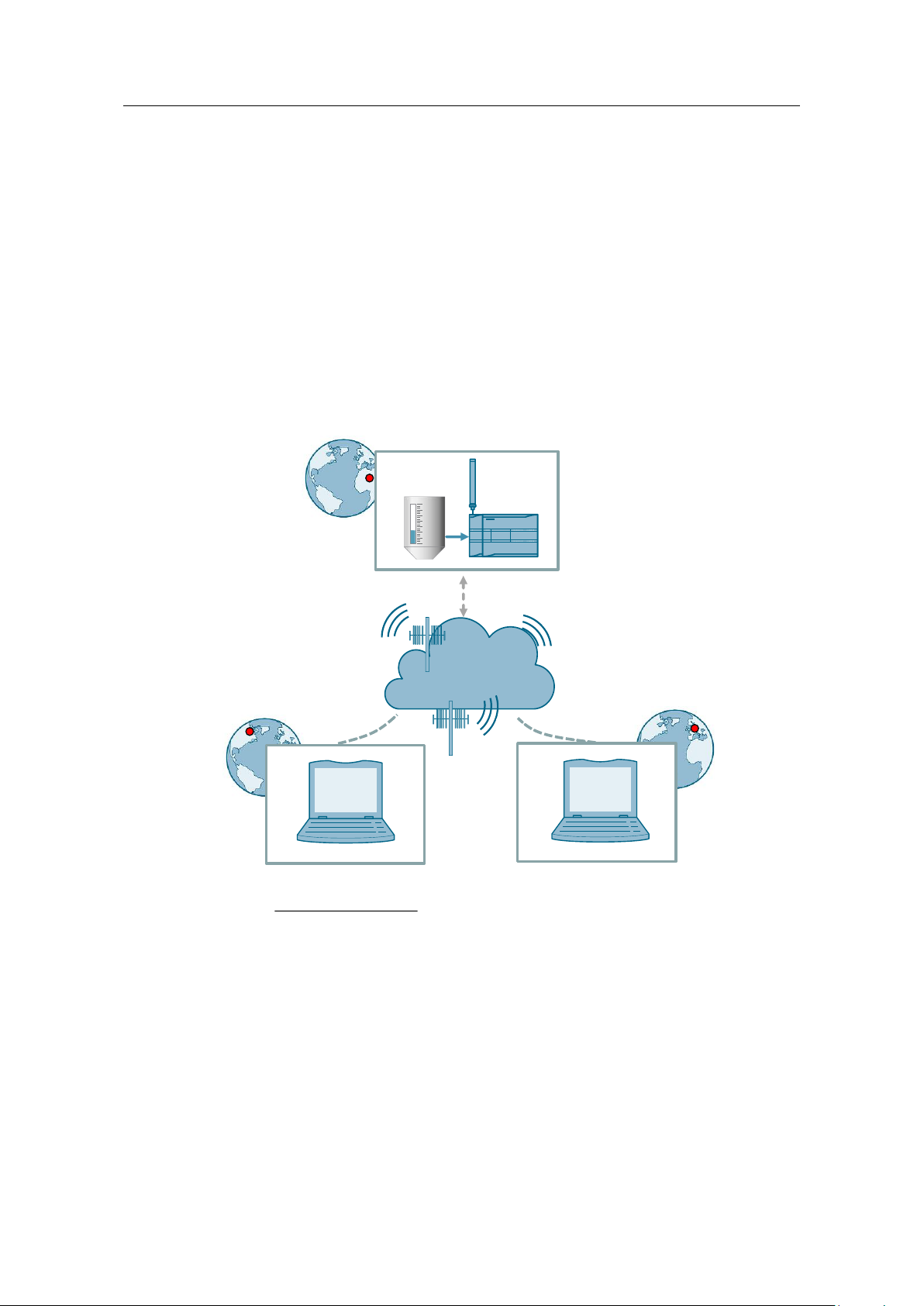
1 Task
Introduction
The infrastructure of a plant contains a SIMATIC S7-1200 sub-station. The substation communicates wirelessly with a central station via the internet. Additionally,
a service operator monitors the sub-station and communicates with it via remote
access.
The communication is realized via the TeleControl Server Basic V3 (TCSB V3)
software installed in the central station.
Overview of the automation task
The following figure provides an overview of the automation task.
Figure 1-1
Requirements
This application example is intended to meet the following requirements:
Via remote access, the service operator monitors the status of the connected
remote stations.
Via remote access, the service operator downloads updated program data and
modifies any parameters.
The remote access is done via the internet and independent from the internet
service provider.
Page 5
2 Solution
2.1 Overview
TeleService with TCSB
Entry-ID: 56720905, V1.0, 10/2016
5
Siemens AG 2016 All rights reserved
S7-1200 with
CP 1242-7 V2
TCSB
Mobile network
Central Station
Remote Station
Programming Unit
Engineering Station
TCSB V3
Teleservice
Process value transmission
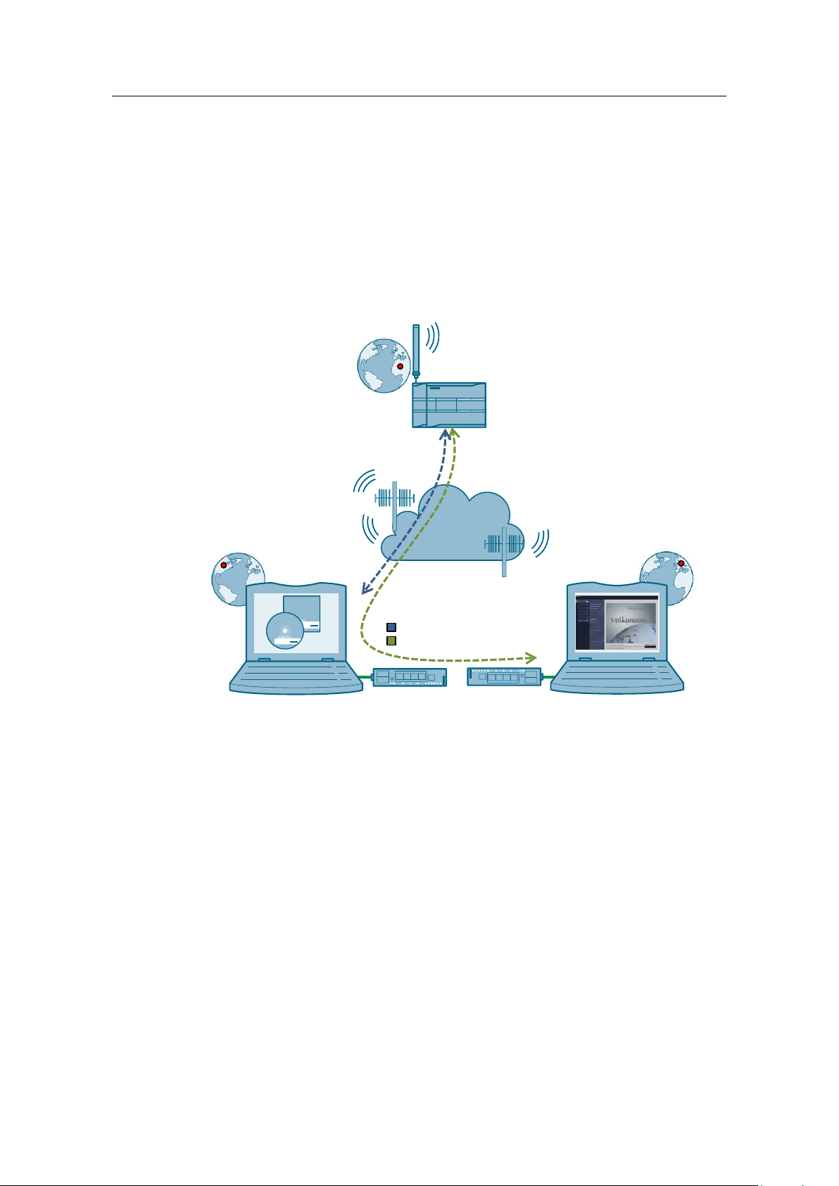
2 Solution
2.1 Overview
Schematic layout
The figure below shows a schematic overview of the most important components of
the solution.
Figure 2-1
Setup
With TCSB V3, the central and the remote station can communicate with each
other via the mobile network. The central station is connected with the internet via
a DSL router.
The remote maintenance (TeleService) requires an uninterrupted data transfer
between the remote station and the engineering station via the GPRS network. The
connection between the engineering station and the GPRS network is established
by TCSB V3.
The engineering station is connected to the internet with the following alternative
technologies:
UMTS (e. g. USB-Stick)
Router (e. g with integrated DSL-modem)
Page 6

2 Solution
2.1 Overview
TeleService with TCSB
Entry-ID: 56720905, V1.0, 10/2016
6
Siemens AG 2016 All rights reserved
Note
The connection between the engineering station and the GPRS network can also
be established via a TeleService gateway.
The TeleService gateway only serves the “TeleService” function via the mobile
network. With the TeleService gateway, no connections to remote stations can
be monitored and no process data can be transferred (see \5\).
The “TS Gateway” software is included in the scope of delivery of the CP 1242-7
GPRS V2.
Note
In this application example, central station and engineering station have been
integrated into one device.
Remote Station
“Remote Station” refers to a spatially removed remote station with a SIMATIC S7-
1200 CPU and a CP 12427 GPRS V2.
Central station
“Central station” refers to a central control unit (PC, IPC or comparable device) with
internet connection, onto which the TCSB V3 software is installed.
Engineering Station
Engineering Station (ES) refers to a programming device, notebook or a
comparable device with software component STEP 7 V13 SP1 and an existing
internet connection.
Advantages
The solution offers you the following advantages:
TCSB V3 enables economic data communication between remote stations and
the central station.
World-wide access to the remote station is possible via the internet.
The application example can also be used for the CP 1243-7 LTE.
The core application areas are industrial applications where the objective is to
send data in a cost-effective way on a wireless basis, for example in water
treatment plants, for water purification or in pumping stations.
Topics not covered by this application
This application example does not contain a description of:
SIMATIC NET TeleControl Server Basic (see also \3\)
LAD/ FBD/ STL/ SCL programming languages
Basic knowledge of these topics is assumed.
Page 7
2 Solution
2.2 Hardware and software components
TeleService with TCSB
Entry-ID: 56720905, V1.0, 10/2016
7
Siemens AG 2016 All rights reserved
Component
Qty
Article number
Note
S7-1200 PM1207
1
6EP1332-1SH71
Power supply
SIMATIC S7-1200
CPU 1217C
DC/DC/DC
1
6ES7217-1AG40-0XB0
Any S7-1200 CPU as of V4.1
can be used.
COMMUNICATION
PROCESSOR
CP 1242-7 V2
1
6GK7242-7KX31-0XE0
Alternatively, a CP 1243-7
LTE can also be used:
CP 1243-7 LTE EU
(6GK7243-7KX30-0XE0)
CP 1243-7 LTE US
(6GK7243-7SX30-0XE0)
Antenna ANT7944MR
1
6NH9860-1AA00
GSM quad-band and UMTS
and LTE (Europe).
SIMATIC memory
card
1
6ES7954-8LF01-0AA0
Memory card for the S7-1200
CPU (optional).
Component
Qty
Article number
Note
SIM card
1
Available from your mobile
communications provider
Activated for data
communication.
DSL router and
modem
2
Specialist retailers
SCALANCE M816
Fixed IP address for
DSL (broadband)
connection
or
DynDNS
2
Available from your provider.
-
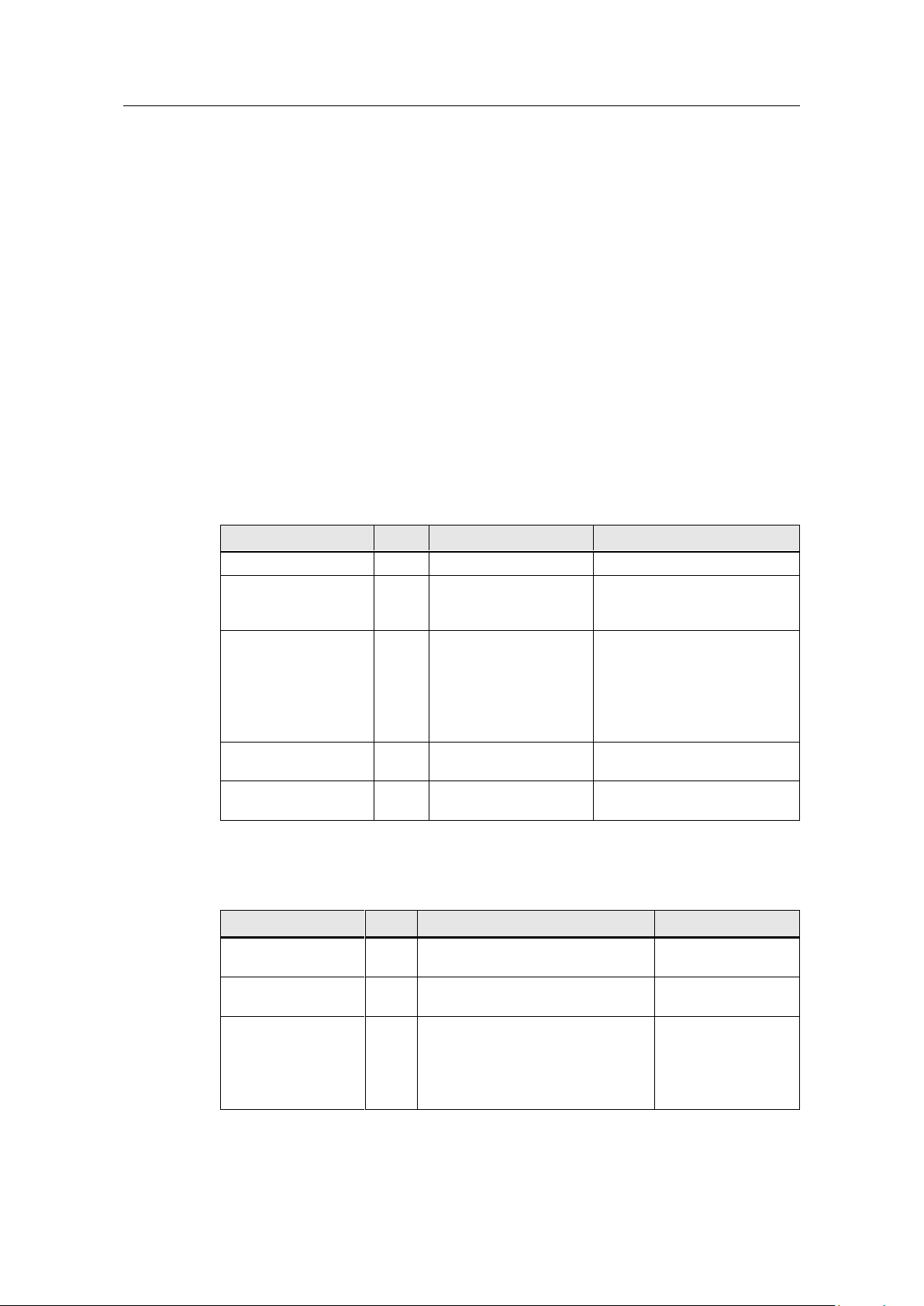
2.2 Hardware and software components
2.2.1 Validity
This application example is valid for the following software versions:
CP 1242-7 V2
CP 1243-7 LTE
STEP 7 V13 SP1
S7-1200 CPU V4.1 or higher
TCSB V3 SP1
2.2.2 Components used
This application example was created with the following components:
Hardware components of station 1
Table 2-1
Accessories
Table 2-2
Page 8
2 Solution
2.2 Hardware and software components
TeleService with TCSB
Entry-ID: 56720905, V1.0, 10/2016
8
Siemens AG 2016 All rights reserved
Component
Qty
Article number
Note
STEP 7 Professional
V13 SP1
1
6ES7822-1AA03-0YA5
STEP 7 Basic can also be
used.
Software TCSB V3
SP1
1
6NH9910-0AA21-0AA0
A maximum of eight
connectable stations.
The product is available in
further stages of
development and licenses,
(see document \3\).
Component
Note
56720905_S7_1200_TeleService_PROJ_V10.zip
This zip file includes:
The STEP 7 V13 project
TCSB project
56720905_S7_1200_TeleService_DOC_V10_de.pdf
This document.
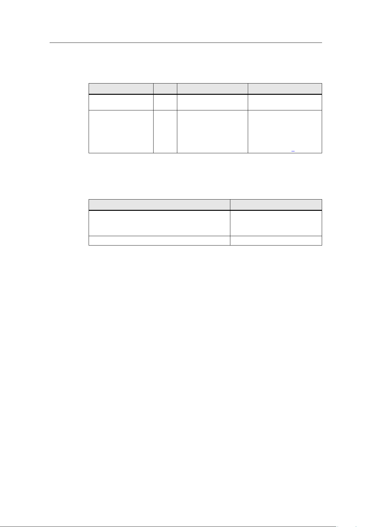
Software components
Table 2-3
Example files and projects
The following table contains all files and projects used in this example.
Table 2-4
Page 9
3 Function principle
3.1 Connection buildup between remote station and central station via TCSB V3
TeleService with TCSB
Entry-ID: 56720905, V1.0, 10/2016
9
Siemens AG 2016 All rights reserved
TCSB V3
4. Port
5. Project number
Station number
TeleControl password
6. IP address of
TCSB
3. Fixed IP address
4. Port
6. IP address of
TCSB
GSM/ GPRS
Central Station
1. PIN
2. APN, APN user,
APN password
3. Fixed IP address
4. Port
5. Project number
Station number
TeleControl password
1. PIN
2. APN
Remote Station
Note
The SIM card’s PIN number must be enabled.
3 Function principle
This application example shows the following core elements:
Configuration of a S7-1200 station with CP 1242-7 V2 for communication with
the central station via mobile communications network and the internet.
Configuration of a S7-1200 station with CP 1242-7 V2 for remote maintenance
(TeleService) of the remote station that is operated by a service operator.
How the remote station can be maintained by a service operator.
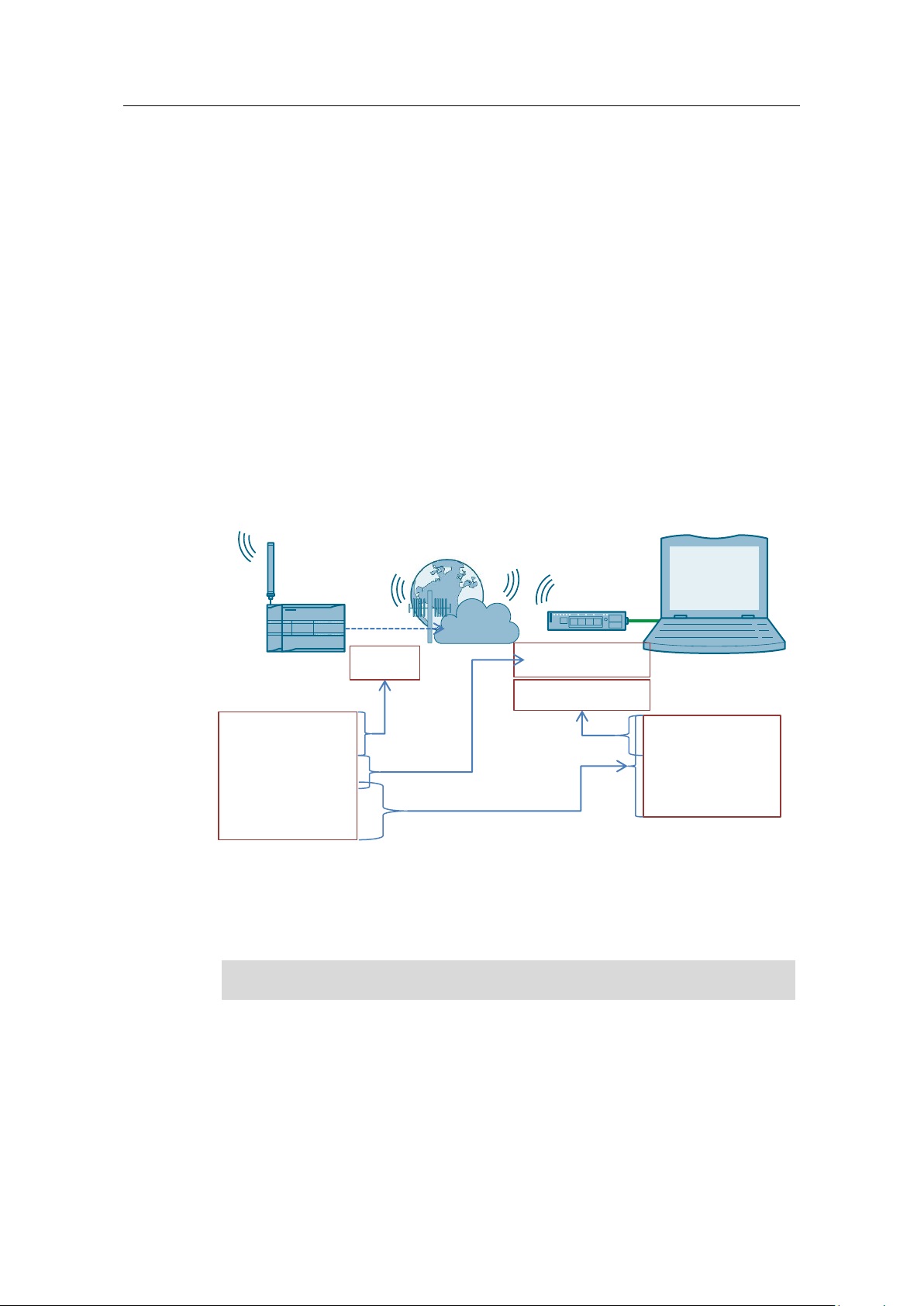
3.1 Connection buildup between remote station and
central station via TCSB V3
The following diagram shows the complete system with all parameters required for
communication between the remote station and the central station. In this
application example, the connection is established via TCSB V3.
Figure 3-1
1. PIN number of the SIM card that is installed into the CP 1242-7 V2.
The CP 1242-7 V2 logs in automatically at the GSM network of the provider,
given that the PIN number of the installed SIM card has been recognized as
valid.
2. APN
The CP 1242-7 V2 logs in at the GPRS access point of the mobile service
provider using the APN address, APN user name and APN user password. An
IP address from the address area of the provider is assigned to the CP 1242-7
V2. It is now accessible via internet and can send IP-based requests to other
participants on the internet.
Page 10

3 Function principle
3.1 Connection buildup between remote station and central station via TCSB V3
TeleService with TCSB
Entry-ID: 56720905, V1.0, 10/2016
10
Siemens AG 2016 All rights reserved
Note
The APN user name and the APN user password are provider-dependent
3. Fixed IP address
The CP 1242-7 V2 sends a connection request to the central station. The static
IP address of the internet connection for accessing the central station is
required.
4. Port
As soon as the connection request has been received by the router of the local
IT network of the central station, it will be forwarded to the central station with
the relevant port number.
5. Project number, station number and TeleControl password
TCSB V3 checks the connections request of the CP 1242-7 V2, using the data
(project number and station number) stored in the configuration.
To authenticate the remote station, an additional password is requested.
If the connection request is evaluated successfully the TCSB V3 updates the
internal routing table entry related to this remote station and the corresponding
current IP address of the CP 1242-7 V2. A connection for the transmission of
TCP/IP packages is established between the CP 1242-7 V2 of the remote
station and the central station.
6. IP address of TCSB V3
Page 11
3 Function principle
3.2 Teleservice connection between remote station and engineering station
TeleService with TCSB
Entry-ID: 56720905, V1.0, 10/2016
11
Siemens AG 2016 All rights reserved
TCSB
Central Station
Remote Station
Engineering Station
TCSB V3
GSM/ GPRS
4. Teleservice user name
Teleservice password
1. IP address of TCSB
2. Port
3. Server password
4. Teleservice user name
Teleservice password
2. Port
3. Server password
2. Port
Teleservice
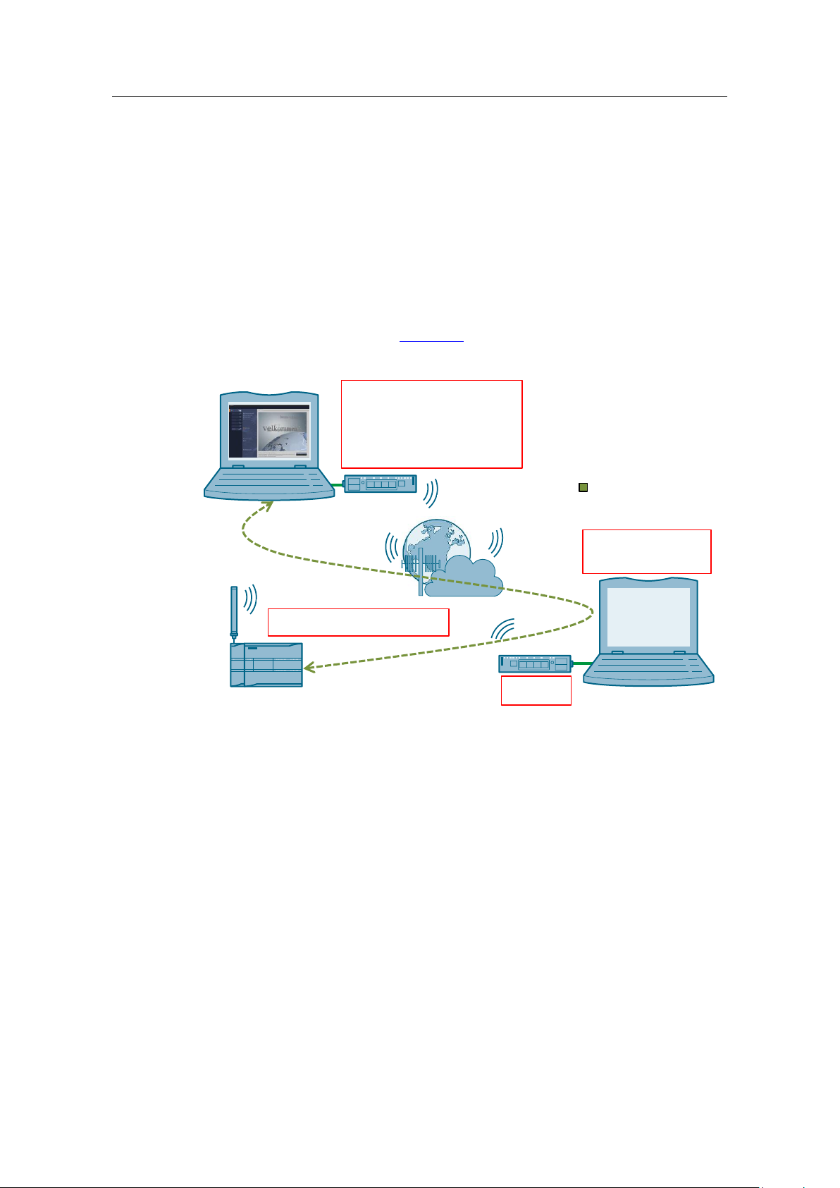
3.2 Teleservice connection between remote station and
engineering station
As engineering station and remote station always communicate via the central
station, the central and the remote station need to be connected via the TCSB V3
in this application example. The TeleService connection for loading project or
program data or querying diagnostic data is directly integrated in the main
connection.
The graphic below shows the complete system with all parameters required for a
teleservice communication between remote station and engineering station in
addition to the parameters from Figure 3-1.
Figure 3-2
1. IP address of TCSB V3
The engineering station sends a connection request to the central station. For
this, the IP address of the TCSB V3 is needed, via which the TeleService
connection between engineering station and remote station is run.
2. Port
As soon as the connection request has been received by the router of the local
IT network of the central station, it will be forwarded to the central station with
the relevant port number.
3. Server password
The TCSB V3 checks the connection request of the engineering station. This
password is used to authenticate the engineering station in the TCSB.
If this remote station is entered in the TCSB V3 and online, the teleservice
request from the engineering station to the remote station is forwarded on the
basis of the existing TCP/IP connection.
Page 12

3 Function principle
3.2 Teleservice connection between remote station and engineering station
TeleService with TCSB
Entry-ID: 56720905, V1.0, 10/2016
12
Siemens AG 2016 All rights reserved
4. TeleService user name and password
For protection against an unauthorized access to the CP 1242-7 V2, the
TeleService user name and password are requested during the start-up of the
TeleService session.
If the teleservice connection request is validated, diagnostic and program data
can then be transferred between the remote station and the engineering
station. The process value communication is not affected by this.
Page 13

4 Configuration and Settings
4.1 Configuring the remote station
TeleService with TCSB
Entry-ID: 56720905, V1.0, 10/2016
13
Siemens AG 2016 All rights reserved
Note
The project included in this application example has already been configured for
you. Chapter 4 explains the implemented work steps again.
No.
Action
1.
Create a STEP 7 V13 project.
2.
Add the S7-1200 CPU (as of V4.1) for the SIMATIC station 1.
3.
Add the CP 1242-7 GPRS V2 to the station.
4 Configuration and Settings
The configuration is done with the following configuration tools:
STEP 7 V13 SP1:
– Configuration of a remote station (S7-1200 CPU with CP 1242-7 GPRS
V2) for data communication with the central station via mobile
communications network and the Internet
– Configuration of a remote station (S7-1200 CPU with CP 1242-7 GPRS
V2) for remote maintenance (TeleService) by a service operator
TCSB V3:
– create and configure a project
– create and configure connections
– configure general parameters
4.1 Configuring the remote station
The table below shows how to configure a S7-1200 station with the
with the CP 1242-7 GPRS V2 for data communication with the central station via
mobile communications network and the Internet and for remote maintenance
(TeleService).
Table 4-1
Page 14

4 Configuration and Settings
4.1 Configuring the remote station
TeleService with TCSB
Entry-ID: 56720905, V1.0, 10/2016
14
Siemens AG 2016 All rights reserved
No.
Action
4.
Activate the following control boxes under Properties of the CP 1242-7 GPRS V2 >
General > Communication types:
“Activate telecontrol communication”
“Activate online functions”
5.
Under “Properties of the CP 1242-7 GPRS V2 > Mobile wireless communications
settings”, make the required mobile communication settings marked in the following
figure.
6.
Enable the security functions. Under “Properties of the CP 1242-7 GPRS V2 >
Security > Security properties”, create a user profile for the security functions.
Page 15

4 Configuration and Settings
4.1 Configuring the remote station
TeleService with TCSB
Entry-ID: 56720905, V1.0, 10/2016
15
Siemens AG 2016 All rights reserved
No.
Action
7.
Under “Properties of the CP 1242-7 GPRS V2 > Partner stations > Connection to
partner”,
configure the CP parameters required to configure the TCSB V3:
Partner IP address (static IP address / provider-dependent)
Partner port
„WAN-IP-ADDRESS“
“Properties > Security > CP identification”
Project number
Station number
Telecontrol password (here “Teleservice”).
The parameters assigned here must be identical to the parameters in TCSB.
Page 16

4 Configuration and Settings
4.1 Configuring the remote station
TeleService with TCSB
Entry-ID: 56720905, V1.0, 10/2016
16
Siemens AG 2016 All rights reserved
No.
Action
8.
Adopt the global security settings that are required or the TeleService access.
Under “Global security settings > User management > Roles”, create a new
user-defined role.
Under “Global security settings > User management > Roles”, create a user
that is allowed to execute the TeleService functions for CP.
User name: “SiemensOS”
Password: “Teleservice”
Role: “teleservice”
Under “Global security settings > User management > Roles > Rights of the
role”, activate the right “Use TeleService”:
9.
Load the project data to the station via your PROFINET interface.
Page 17

4 Configuration and Settings
4.2 Configuring the TCSB V3
TeleService with TCSB
Entry-ID: 56720905, V1.0, 10/2016
17
Siemens AG 2016 All rights reserved
No.
Action
1.
Under “Windows Start menu > All Programs > Siemens Automation > SIMATIC >
TCS Basic > Config and Monitoring Tool”, start the configuration and monitoring
interface of TCSB (CMT).
2.
After the program has started, the login dialog of the CMT appears.
Enter a configured user name or keep the default user name.
Enter the respective password.
Enter the IP address or the TeleControl server name resolved by DNS:
– Computer name
or
– IP address (default IP address: 127.0.0.1)
Default logon data:
User name: administrator
Password: 0000
3.
Create a new project:
In the navigation pane, select the entry "Projects".
In the commands bar, click on the "Add" button.
The new project appears in the navigation pane and in the object area.
4.
Configure the new project:
Select the project in the navigation pane or object area and click on the "Settings"
tab.
4.2 Configuring the TCSB V3
Table 4-2
Page 18

4 Configuration and Settings
4.2 Configuring the TCSB V3
TeleService with TCSB
Entry-ID: 56720905, V1.0, 10/2016
18
Siemens AG 2016 All rights reserved
No.
Action
5.
Fill in the parameters “Project name”, “Project number” and “Server password” of
the project.
Click on “Create”.
Note:
The server password is required for the TeleService access.
In this example, the server password is “Teleservice”.
6.
“Save & activate” the configuration to activate the configuration data for connection
establishment.
7.
Create a new connection for station 1 by following the steps below:
In the navigation pane, select a project for which you want to create a new
connection.
In the command bar, select the required connection type from the “Connection
type” drop-down list.
In the object pane, select the “Add” button from the command bar. Select the
CP 1242-7 V2.
The new connection appears in the object area.
Page 19

4 Configuration and Settings
4.2 Configuring the TCSB V3
TeleService with TCSB
Entry-ID: 56720905, V1.0, 10/2016
19
Siemens AG 2016 All rights reserved
No.
Action
8.
Save the changes and activate the project.
9.
Select the connection and in the object pane, select the “Connections” tab.
In the parameter area, various parameter groups are displayed for this connection.
10.
In the “General” parameter group, enter the parameters for the remote station:
Station name
Station number
Telecontrol password: Teleservice
Note:
The parameters assigned here must be identical with the parameters in the STEP 7
V13 project.
11.
Under “TCSB system > "TCM" tab > General > Address TCM 1”, configure the IP
address and the port of the Telecontrol server.
(„TCSB system > „TCM“ tab > General> Address TCM 1“).
12.
Save the changes and activate the project.
Page 20

5 Installation and Commissioning
5.1 Installing the hardware
TeleService with TCSB
Entry-ID: 56720905, V1.0, 10/2016
20
Siemens AG 2016 All rights reserved
Note
The installation guidelines of all components have to be observed.
NOTICE
Before you switch on the power supply, complete and check the
installation!
Industrial Ethernet
Programming Unit
24 V
CP 1242-7
GPRS V2
CPU 1217C
192.168.0.1
192.168.0.100
No.
Action
1.
Insert your SIM card into the CP 1242-7 GPRS V2.
2.
Connect the individual modules to a suitable module rack.
3.
Connect the CPU with the CP 1242-7 GPRS V2.
4.
Connect the antenna to the CP 1242-7 GPRS V2.
5.
Connect the engineering PG to the PROFINET interface of the S7-CPU.
Note:
This connection is only required while the project data are loaded. Remote
maintenance occurs via the Internet.
6.
Connect the CPU 1217C and the CP 1242-7 GPRS V2 to a 24 V DC power
source.
7.
Connect the DC power source to the power grid
(230 V AC).
5 Installation and Commissioning
5.1 Installing the hardware
The necessary hardware components are listed in Chapter 2.2.
5.1.1 Hardware setup of the remote station
The figure below shows the hardware setup of the remote station with the central
station and the engineering station.
Figure 5-1
Table 5-1
Page 21

5 Installation and Commissioning
5.1 Installing the hardware
TeleService with TCSB
Entry-ID: 56720905, V1.0, 10/2016
21
Siemens AG 2016 All rights reserved
TCSB V3
Central Station
Industrial Ethernet
Internet
(DSL connection)
DSL Router
172.16.0.1
172.16.61.100
Fixed IP address
No.
Action
1.
Connect your PC on which TeleControl Server Basic runs to the router via
Ethernet.
2.
If the DSL (broadband) modem is not integrated in the router, connect the router
to the DSL modem.
Engineering Station
Internet
(DSL connection)
DSL Router
Fixed IP address
Industrial Ethernet
172.16.0.1
172.16.61.100
No.
Action
1.
Establish an internet connection at your engineering station.
Possible access methods:
Access via UMTS (e. g. USB-Stick)
Access via DSL (e. g router with integrated DSL-modem).
5.1.2 Hardware setup of central station
Figure 5-2 below shows the hardware setup of the central station.
Figure 5-2
Table 5-2
5.1.3 Hardware setup of the engineering station
The figure below shows the hardware setup of the engineering station.
Figure 5-3
Table 5-3
Page 22

5 Installation and Commissioning
5.2 Installing the software
TeleService with TCSB
Entry-ID: 56720905, V1.0, 10/2016
22
Siemens AG 2016 All rights reserved
Note
The engineering station and the central station are realized with a single device
in this application example.
No.
Action
Remark
1.
Install STEP 7 V3 SP1.
Follow the instructions of the installation
program.
No.
Action
Remark
1.
Install TeleControl Server Basic
V3 SP1
Follow the instructions of the installation
program.
5.2 Installing the software
Engineering PC/PG
Table 5-4
PC/PG as central station
Table 5-5
Page 23

5 Installation and Commissioning
5.3 Installing the example project
TeleService with TCSB
Entry-ID: 56720905, V1.0, 10/2016
23
Siemens AG 2016 All rights reserved
Module
IP address
Subnet mask
Station 1:
CPU 1217C DC/DC/DC
192.168.0.1
255.255.255.0
Programming unit
192.168.0.100
255.255.255.0
PC/PG central station (TCSB)/
Engineering Station
172.16.61.100
255.255.0.0
LAN IP address of router
172.16.0.1
255.255.0.0
No.
Action
1.
Open the “Internet Protocol (TCP/IP) Properties” via Start > Settings > Network
Connection > Local Connections.
(„Start > Settings > Network Connection >Local Connections”).
2.
In the open window, select the Internet Protocol (TCP/IP) and open Properties.
3.
Fill in the boxes as shown in the figure.
Close the dialog box with “OK”.
5.3 Installing the example project
Unzip the “*zip” file “56720905_S7_1200_TeleService_PROJ_V10”. This folder
contains the following files:
The archived STEP 7 project
“56720905_S7-1200_TeleService_CODE_V10.zip”.
The TCSB configuration file “56720905_S7-1200_TeleService.bak”.
5.4 Commissioning
5.4.1 Setting the IP addresses
The following table shows the configured IP addresses.
Table 5-6
5.4.2 Assigning the IP address to the engineering station
Change the network settings of your engineering station as shown in the following
table.
Table 5-7
Page 24

5 Installation and Commissioning
5.4 Commissioning
TeleService with TCSB
Entry-ID: 56720905, V1.0, 10/2016
24
Siemens AG 2016 All rights reserved
No.
Action
4.
If your PG has an IWLAN interface, disable it.
Note
To configure the router, you have to assign an IP address to your PG/PC that is
in the router’s internal network.
No.
Action
1.
Open the configuration user interface
of the router.
This can be additional software,
“Telnet” or a web page.
2.
Enter the connection data for your
Internet connection.
Login, password, etc. you received
from your provider.
3.
Enter your DNS server.
You will receive the address together
with your access data.
4.
Specify a LAN IP address for the
router.
In this example:
“172.16.0.1”
5.
Forward the partner port.
TCP port 55097 to port 55097 of
172.16.61.100.
5.4.3 Configuring the DSL router
For the configuration, no specific router will be discussed as the screen forms will
differ from router to router.
Table 5-8
Page 25

5 Installation and Commissioning
5.4 Commissioning
TeleService with TCSB
Entry-ID: 56720905, V1.0, 10/2016
25
Siemens AG 2016 All rights reserved
No.
Action
1.
Stop the existing database by stopping the service "TSC Basic Database Service"
by means of the Windows Task Manager in the “Services" tab (as administrator).
2
1
5.4.4 Inserting a backup copy of the “56720905_S7 1200_TeleService.bak” database into TCSB V3
Table 5-9
Page 26

5 Installation and Commissioning
5.4 Commissioning
TeleService with TCSB
Entry-ID: 56720905, V1.0, 10/2016
26
Siemens AG 2016 All rights reserved
No.
Action
2.
As administrator, start the SQL Server Management Studio under “Start > All
Programs > Microsoft SQL Server 2008 R2 > SQL Server Management Studio”.
The "Connect to server" dialog opens with the following settings:
Server type: Database Engine
Server name: <PC name>\TCSB
Authentication: Windows Authentication
3.
Keep all settings and click on "Connect".
SQL Server Management Studio opens with the database’s
object navigation.
4.
Select the “Databases” item.
Page 27

5 Installation and Commissioning
5.4 Commissioning
TeleService with TCSB
Entry-ID: 56720905, V1.0, 10/2016
27
Siemens AG 2016 All rights reserved
No.
Action
5.
Select the context menu (right mouse button) "Restore Database...".
The “Restore Database - TCSB” dialog opens.
6.
In the "Destination for restore" field, select the database ("To database")
"TCSB".
In the "Source for restore" field, activate the option ("From device") and open
the "Specify Backup" dialog via the "..." button.
Select the “56720905_S7-1200_TeleService.bak” backup copy by first opening
the file browser using the “Add” button.
7.
In the "Restore Database - TCSB" dialog, select the selected “backup set” in the
"Restore" column and click on "OK".
8.
Click “OK” to close Management Studio.
9.
Restart the computer.
1
2
3
Page 28

5 Installation and Commissioning
5.4 Commissioning
TeleService with TCSB
Entry-ID: 56720905, V1.0, 10/2016
28
Siemens AG 2016 All rights reserved
No.
Action
1.
Start the configuration and monitoring interface of TCSB (CMT) under “Windows
Start menu > All Programs > Siemens Automation > SIMATIC > TCS Basic >
Config and Monitoring Tool”:
2.
After the program has started, the login dialog of the CMT appears.
User name: “administrator”
Password: “administrator”
Enter the IP address or the TeleControl server name resolved by DNS:
– Computer name
or
– IP address (default IP address: 127.0.0.1)
3.
Configure the IP address and the ports of the TeleControl server:
“TCSB system > "TCM" tab > General > Address TCM 1”
(„TCSB system > "TCM" tab > General > Address TCM 1”).
4.
Save the changes and activate the project.
5.
Restart the computer.
5.4.5 Configuring the IP address and ports of TCSB V3
Table 5-10
Page 29

5 Installation and Commissioning
5.4 Commissioning
TeleService with TCSB
Entry-ID: 56720905, V1.0, 10/2016
29
Siemens AG 2016 All rights reserved
No.
Action
1.
Unzip the project “39863979_S7-1200_TeleService_CODE_V10.zip”.
2.
Open the STEP 7 V13 project “CP1242-7_V2_Teleservice.ap13”.
3.
Activate the security functions of the CP under “CP1242-7_V2_Teleservice > Global
security settings > User login”:
User name: “administrator”
Password: “administrator”
4.
Under
“Properties of the CP 1242-7 GPRS V2
> Mobile wireless communications
settings”, adjust the mobile
communication settings of the CP 12427 GPRS V2:
PIN
APN settings
Teleservice settings
5.4.6 Loading the remote station
Prerequisites
There is an existing connection between your engineering station and the CPU
(e. g. via the PROFINET interface).
The CPU must be in an operation mode that allows loading.
Prior to loading the user program, a general reset of the CPU should be
performed to ensure that none of the "old" blocks still exist on the CPU.
Table 5-11
Page 30

5 Installation and Commissioning
5.4 Commissioning
TeleService with TCSB
Entry-ID: 56720905, V1.0, 10/2016
30
Siemens AG 2016 All rights reserved
No.
Action
5.
Under “Properties of the CP 1242-7 GPRS V2 > Partner stations > Connection to
partner”, adjust the partner IP address (fixed IP address of your DSL router)
required for the connection to the TeleControl server in the central station.
„WAN-IP-ADDRESS“
6.
Select the station “CP1242-7_Teleservice”.
7.
Download the project into the remote station.
Note:
The PN/IE interface is used for loading the project data. The loading occurs via the
PROFINET interface of the station. After loading the project data, the PROFINET
interface is no longer used. Remote maintenance occurs via the internet.
8.
After having loaded the configuration, a connection to the TCSB V3 is established.
Page 31

6 Operating the Application Example
6.1 Polling diagnostic data from the station
TeleService with TCSB
Entry-ID: 56720905, V1.0, 10/2016
31
Siemens AG 2016 All rights reserved
No.
Action
1.
Make sure that the engineering station is connected to the internet.
Note
Check the internet connection at your engineering station with the help of the
internet browser by calling up a random internet page.
2.
Select the station “CP1242-7_V2_Teleservice” and establish the online connection.
3.
As PG/PC interface type, select “TeleService via mobile wireless” and as PG/PC
interface “Mobile wireless TeleService board”.
4.
Establish the TeleService connection between engineering and remote station by
clicking on the mobile phone symbol.
6 Operating the Application Example
The following chapters show how to wirelessly monitor and control the remote
station. An existing connection of the remote station to the central station is
required for this (TCSB V3) (see Table 5-11, step no. 8).
6.1 Polling diagnostic data from the station
Table 6-1
Page 32

6 Operating the Application Example
6.1 Polling diagnostic data from the station
TeleService with TCSB
Entry-ID: 56720905, V1.0, 10/2016
32
Siemens AG 2016 All rights reserved
No.
Action
5.
Enter the following values and then click on “Connect”:
IP address of the server (172.16.61.100)
The server password (Teleservice)
The port (55097)
The TeleService user name (SiemensOS)
The TeleService password (Teleservice)
6.
The TeleService connection has been established.
Page 33

6 Operating the Application Example
6.1 Polling diagnostic data from the station
TeleService with TCSB
Entry-ID: 56720905, V1.0, 10/2016
33
Siemens AG 2016 All rights reserved
No.
Action
7.
Start searching for accessible participants by clicking on “Start search”.
8.
Select the remote station and establish the online connection.
9.
Remote maintenance of the station is now possible.
Page 34

6 Operating the Application Example
6.1 Polling diagnostic data from the station
TeleService with TCSB
Entry-ID: 56720905, V1.0, 10/2016
34
Siemens AG 2016 All rights reserved
No.
Action
10.
Open the device configuration of the station
“CP1242-7_V2_Teleservice”.
11.
Select the CP 1242-7 V2 and open the online diagnostics (right mouse-click).
12.
Now select the respective topic in “Diagnostics” to call up the information of the CP
1242-7.
Page 35

6 Operating the Application Example
6.2 Downloading project and program data from the STEP 7 project into the remote station
TeleService with TCSB
Entry-ID: 56720905, V1.0, 10/2016
35
Siemens AG 2016 All rights reserved
No.
Action
1.
Ensure that the engineering station is connected to the internet.
Note:
Check the internet connection at your engineering station with the help of the
internet browser by calling up a random internet page.
2.
Ensure that STEP 7 V13 on your engineering station is not in online mode.
3.
Select the project content to be transferred to the remote station:
Hardware and software (changes only)
Hardware configuration
Software (changes only)
4.
As PG/PC interface type, select “TeleService via mobile wireless” and as PG/PC
interface “Mobile wireless TeleService board”.
6.2 Downloading project and program data from the STEP
7 project into the remote station
Table 6-2
Page 36

6 Operating the Application Example
6.2 Downloading project and program data from the STEP 7 project into the remote station
TeleService with TCSB
Entry-ID: 56720905, V1.0, 10/2016
36
Siemens AG 2016 All rights reserved
No.
Action
5.
Establish the TeleService connection between engineering and remote station by
clicking on the mobile phone symbol.
6.
Enter the following values and then click on “Connect”:
The IP address of the server (172.16.61.100)
The server password (Teleservice)
The port (55097)
The TeleService user name (SiemensOS)
The TeleService password (Teleservice)
Page 37

6 Operating the Application Example
6.2 Downloading project and program data from the STEP 7 project into the remote station
TeleService with TCSB
Entry-ID: 56720905, V1.0, 10/2016
37
Siemens AG 2016 All rights reserved
No.
Action
7.
The TeleService connection has been established:
8.
Start searching for accessible participants by clicking on “Start search”.
9.
Select the remote station and load the project or program data by clicking on
“Load”.
Page 38

7 Links & Literature
TeleService with TCSB
Entry-ID: 56720905, V1.0, 10/2016
38
Siemens AG 2016 All rights reserved
Topic
\1\
Siemens Industry Online Support
http://support.industry.siemens.com
\2\
Download page of the entry
https://support.industry.siemens.com/cs/ww/en/view/56720905
\3\
SIMATIC NET Industrial Remote Communication -TeleControl
TeleControl Server Basic V3
https://support.industry.siemens.com/cs/ww/en/view/107536367
\4\
SIMATIC NET S7-1200 – TeleControl CP 1242-7 GPRS V2 – Manual
https://support.industry.siemens.com/cs/ww/en/view/109476700
\5\
SIMATIC NET Industrial Remote Communication TeleService TS Gateway Manual
https://support.industry.siemens.com/cs/ww/en/view/107535103
Version
Date
Modifications
V1.0
10/2016
First version
7 Links & Literature
Table 7-1
8 History
Table 8-1
 Loading...