

Siemens SIMATIC S7-1200 CP 1243-8 IRC Operating Instructions Manual

___________________
___________________
___________________
___________________
___________________
___________________
___________________
___________________
___________________
___________________
___________________
___________________
___________________
SIMATIC NET
S7-1200 - TeleControl
CP 1243-8 IRC
Operating Instructions
02/2018
C79000
Preface
Application and functions
1
LEDs and connectors
2
Installation, connecting up,
commissioning
3
Configuration
4
Program blocks
5
Diagnostics and upkeep
6
Technical data
7
Approvals
A
Dimension drawings
B
Accessories
C
STEP 7 V5 configuration of
the proxy
D
Documentation references
E
-G8976-C385-03

Siemens AG
Division Process Industries and Drives
Postfach 48 48
90026 NÜRNBERG
GERMANY
C79000-G8976-C385-03
Ⓟ
Copyright © Siemens AG 2015 - 2018.
All rights reserved
Legal information
Warning notice system
DANGER
indicates that death or severe personal injury will result if proper precautions are not taken.
WARNING
indicates that death or severe personal injury may result if proper precautions are not taken.
CAUTION
indicates that minor personal injury can result if proper precautions are not taken.
NOTICE
indicates that property damage can result if proper precautions are not taken.
Qualified Personnel
personnel qualified
Proper use of Siemens products
WARNING
Siemens products may only be used for the applications described in the catalog and in the relevant technical
maintenance are required to ensure that the products operate safely and without any problems. The permissible
ambient conditions must be complied with. The information in the relevant documentation must be observed.
Trademarks
Disclaimer of Liability
This manual contains notices you have to observe in order to ensure your personal safety, as well as to prevent
damage to property. The notices referring to your personal safety are highlighted in the manual by a safety alert
symbol, notices referring only to property damage have no safety alert symbol. These notices shown below are
graded according to the degree of danger.
If more than one degree of danger is present, the warning notice representing the highest degree of danger will
be used. A notice warning of injury to persons with a safety alert symbol may also include a warning relating to
property damage.
The product/system described in this documentation may be operated only by
task in accordance with the relevant documentation, in particular its warning notices and safety instructions.
Qualified personnel are those who, based on their training and experience, are capable of identifying risks and
avoiding potential hazards when working with these products/systems.
Note the following:
documentation. If products and components from other manufacturers are used, these must be recommended
or approved by Siemens. Proper transport, storage, installation, assembly, commissioning, operation and
All names identified by ® are registered trademarks of Siemens AG. The remaining trademarks in this publication
may be trademarks whose use by third parties for their own purposes could violate the rights of the owner.
We have reviewed the contents of this publication to ensure consistency with the hardware and software
described. Since variance cannot be precluded entirely, we cannot guarantee full consistency. However, the
information in this publication is reviewed regularly and any necessary corrections are included in subsequent
editions.
for the specific
02/2018 Subject to change

Preface
Validity of this manual
CP 1243-8 IRC
Purpose of the manual
This document contains information on the following product:
●
Article number 6GK7 243-8RX30-0XE0
Hardware product version 2
Firmware version V3.1
The CP is the communications processor for connection of the SIMATIC S7-1200 via
public or private infrastructures to a telecontrol master station. For information on the
telecontrol protocols used refer to the section Properties of the CP (Page 11).
With the help of VPN technology and the firewall, the CP allows protected access to the
S7-1200.
The CP can also be used as an additional Ethernet interface of the CPU for S7
communication.
CP 1243-8 IRC
Operating Instructions, 02/2018, C79000-G8976-C385-03
Figure 1 CP 1243-8 IRC
Behind the top hinged cover of the module housing, you will see the hardware product
version to the right of the article number printed as a placeholder "X". If the printed text is, for
example, "X 2 3 4", "X" would be the placeholder for hardware product version 1.
You will find the MAC address under the lower hinged cover of the housing.
This manual describes the properties of this module and supports you when installing and
commissioning it.
The required configuration steps are described as an overview and there are explanations of
the relationship between firmware functions and configuration.
3

Preface
Product names and abbreviations
CP
IRC
STEP 7
Proxy
ST7
New in this issue
Replaced manual issue
Current manual release on the Internet
Required experience
You will also find information about the diagnostics options of the device.
The following short forms are used in this document:
●
The short form is used instead of the full product name "CP 1243-8 IRC".
●
Industrial Remote Communication
●
Short form for the following versions of the configuration tool STEP 7:
– STEP 7 V5
– STEP 7 Basic
The short form "STEP 7" is only used when the product is self-explanatory in the
particular context.
For information on the product versions, refer to the section Requirements for operation
(Page 23).
●
"PROXY CP1243-8 IRC", substitute module for the CP 1243-8 IRC in the catalog of
STEP 7 V5 / HW Config.
●
Short form for the telecontrol protocol "SINAUT ST7"
Connection to SINEMA Remote Connect of the above firmware version
Edition 07/2017
You will also find the current version of this manual on the Internet pages of Siemens
Industry Online Support at the following address:
Link: (https://support.industry.siemens.com/cs/ww/en/ps/21162/man)
To install, commission and operate the CP, you require experience in the following areas:
● Automation engineering
● Setting up the SIMATIC S7-1200 system
● SIMATIC STEP 7 Basic
CP 1243-8 IRC
4 Operating Instructions, 02/2018, C79000-G8976-C385-03

Preface
Requirements for use of the module
Cross references
Sources of information and other documentation
License conditions
Note
Open source software
The product contains open source software. Read the license conditions for open source
software carefully before using the product.
Security information
You will find the requirements for using the module in the section Requirements for operation
(Page 23).
In this manual there are often cross references to other sections.
To be able to return to the initial page after jumping to a cross reference, some PDF readers
support the command <Alt>+<left arrow>.
You will find an overview of further reading and references in the Appendix of this manual.
You will find the license conditions on the supplied data medium:
● OSS_CP1243-8_99.pdf
Siemens provides products and solutions with industrial security functions that support the
secure operation of plants, systems, machines and networks.
In order to protect plants, systems, machines and networks against cyber threats, it is
necessary to implement – and continuously maintain – a holistic, state-of-the-art industrial
security concept. Siemens’ products and solutions constitute one element of such a concept.
Customers are responsible for preventing unauthorized access to their plants, systems,
machines and networks. Such systems, machines and components should only be
connected to an enterprise network or the internet if and to the extent such a connection is
necessary and only when appropriate security measures (e.g. firewalls and/or network
segmentation) are in place.
Additionally, Siemens’ guidance on appropriate security measures should be taken into
account. For additional information on industrial security measures that may be
implemented, please visit
Link: (http://www.siemens.com/industrialsecurity)
Siemens’ products and solutions undergo continuous development to make them more
secure. Siemens strongly recommends that product updates are applied as soon as they are
available and that the latest product versions are used. Use of product versions that are no
longer supported, and failure to apply the latest updates may increase customers’ exposure
to cyber threats.
CP 1243-8 IRC
Operating Instructions, 02/2018, C79000-G8976-C385-03
5

Preface
Firmware
SIMATIC NET glossary
Training, Service & Support
Recycling and disposal
To stay informed about product updates, subscribe to the Siemens Industrial Security RSS
Feed under
Link: (http://www.siemens.com/industrialsecurity)
For the security functions, see also the following section:
Security functions (Page 20)
Security recommendations (Page 55)
Security (Page 104)
The firmware is signed and encrypted. This ensures that only firmware created by Siemens
can be downloaded to the device.
Explanations of many of the specialist terms used in this documentation can be found in the
SIMATIC NET glossary.
You will find the SIMATIC NET glossary here:
● SIMATIC NET Manual Collection or product DVD
The DVD ships with certain SIMATIC NET products.
● On the Internet under the following entry ID:
Link: (https://support.industry.siemens.com/cs/ww/en/view/50305045)
You will find information on Training, Service & Support in the multi--language document
"DC_support_99.pdf" on the data medium supplied with the documentation.
The product is low in pollutants, can be recycled and meets the requirements of the WEEE
directive 2012/19/EU "Waste Electrical and Electronic Equipment".
Do not dispose of the product at public disposal sites. For environmentally friendly recycling
and the disposal of your old device contact a certified disposal company for electronic scrap
or your Siemens contact.
Keep to the local regulations.
You will find information on returning the product on the Internet pages of Siemens Industry
Online Support:
Link: (https://support.industry.siemens.com/cs/ww/en/view/109479891)
CP 1243-8 IRC
6 Operating Instructions, 02/2018, C79000-G8976-C385-03

Table of contents
Preface ................................................................................................................................................... 3
1 Application and functions ...................................................................................................................... 11
2 LEDs and connectors ............................................................................................................................ 39
3 Installation, connecting up, commissioning ............................................................................................ 47
4 Configuration ........................................................................................................................................ 55
1.1 PG routing ............................................................................................................................... 11
1.2 Properties of the CP ................................................................................................................ 11
1.3 Communications services ....................................................................................................... 14
1.4 Connection to SINEMA RC ..................................................................................................... 17
1.5 Other services and properties ................................................................................................. 19
1.6 Security functions .................................................................................................................... 20
1.7 Performance data and configuration limits ............................................................................. 22
1.8 Requirements for operation .................................................................................................... 23
1.9 Configuration examples .......................................................................................................... 25
1.9.1 Configurations with the ST7 protocol ...................................................................................... 25
1.9.2 Configurations with the DNP3 / IEC protocols ........................................................................ 31
1.9.3 Remote maintenance with SINEMA RC ................................................................................. 34
1.10 Expansion of SINAUT projects ............................................................................................... 35
1.10.1 Modules for new SINAUT projects and those to be expanded ............................................... 35
1.10.2 Requirements for the expansion ............................................................................................. 37
2.1 Opening the covers of the housing ......................................................................................... 39
2.2 LEDs ....................................................................................................................................... 40
2.3 Electrical connectors ............................................................................................................... 45
2.3.1 Power supply .......................................................................................................................... 45
2.3.2 Ethernet interface X1P1 .......................................................................................................... 46
2.3.3 Serial connection for TS module ............................................................................................. 46
3.1 Important notes on using the device ....................................................................................... 47
3.1.1 Notices about use in hazardous areas ................................................................................... 47
3.1.2 Notices about use in hazardous areas according to ATEX .................................................... 48
3.1.3 Notices about use in hazardous areas according to UL HazLoc ............................................ 49
3.2 Installing, connecting up and commissioning ......................................................................... 49
3.3 Note on operation ................................................................................................................... 54
4.1 Security recommendations ..................................................................................................... 55
4.2 Required STEP 7 products ..................................................................................................... 58
4.3 Overview: Connection to LAN / WAN ..................................................................................... 59
CP 1243-8 IRC
Operating Instructions, 02/2018, C79000-G8976-C385-03
7

Table of contents
4.4 Basic communication mechanisms ........................................................................................ 61
4.4.1 Addressing, authentication, connections (single / redundant) ............................................... 61
4.4.1.1 ST7 ......................................................................................................................................... 61
4.4.1.2 DNP3 / IEC ............................................................................................................................. 63
4.4.2 Connection establishment ...................................................................................................... 64
4.4.3 Acknowledgment .................................................................................................................... 65
4.5 Configuration in STEP 7 Basic ............................................................................................... 66
4.6 Communication types ............................................................................................................ 67
4.7 Telecontrol via SINEMA RC ................................................................................................... 68
4.8 Ethernet interface ................................................................................................................... 70
4.8.1 WAN settings ......................................................................................................................... 70
4.8.2 CP identification ..................................................................................................................... 71
4.8.3 Time-of-day synchronization .................................................................................................. 72
4.8.4 Ethernet addresses ................................................................................................................ 72
4.8.5 Advanced options .................................................................................................................. 72
4.8.5.1 MSC protocol settings ............................................................................................................ 72
4.8.5.2 TCP connection monitoring .................................................................................................... 74
4.8.5.3 Transmission settings - ST7 .................................................................................................. 75
4.8.5.4 Transmission settings – DNP3 ............................................................................................... 75
4.8.5.5 Transmission settings - IEC ................................................................................................... 77
4.8.6 Access to the Web server ...................................................................................................... 79
4.9 Serial interface ....................................................................................................................... 79
4.9.1 Configuration of the serial interface ....................................................................................... 79
4.9.2 Configuring a TS module ....................................................................................................... 80
4.9.3 WAN settings ......................................................................................................................... 81
4.9.4 WAN parameters (networking the CP)................................................................................... 82
4.9.5 Advanced options .................................................................................................................. 84
4.9.5.1 Dedicated line ........................................................................................................................ 84
4.9.5.2 Dialup network ....................................................................................................................... 86
4.10 Partner stations ...................................................................................................................... 90
4.10.1 Importing configuration data (ST7) ........................................................................................ 90
4.10.2 Partners (DNP3 / IEC) ........................................................................................................... 91
4.11 Communication with the CPU ................................................................................................ 95
4.11.1 Communication with the CPU ................................
................................................................ 95
4.11.2 CP diagnostics ....................................................................................................................... 96
4.11.3 Partner status / path status .................................................................................................... 97
4.12 Time-of-day synchronization ................................................................................................ 100
4.13 SMSC ................................................................................................................................... 103
4.14 Subscriber numbers ............................................................................................................. 103
4.15 SNMP ................................................................................................................................... 104
4.16 Security ................................................................................................................................ 104
4.16.1 Security user ........................................................................................................................ 105
4.16.2 MSC authentication .............................................................................................................. 105
4.16.3 DNP3 security options ......................................................................................................... 106
4.16.4 Firewall ................................................................................................................................. 108
4.16.4.1 Pre-check of messages by the MAC firewall. ...................................................................... 108
CP 1243-8 IRC
8 Operating Instructions, 02/2018, C79000-G8976-C385-03

Table of contents
5 Program blocks ................................................................................................................................... 167
6 Diagnostics and upkeep ...................................................................................................................... 171
4.16.4.2 Firewall settings for configured connection connections via a VPN tunnel .......................... 108
4.16.4.3 Settings for online security diagnostics and downloading to station with the firewall
activated ................................................................................................................................ 109
4.16.4.4 Notation for the source IP address (advanced firewall mode) .............................................. 109
4.16.5 Time-of-day synchronization ................................................................................................. 109
4.16.6 E-mail configuration .............................................................................................................. 110
4.16.7 Log settings - Filtering of the system events ........................................................................ 111
4.16.8 VPN ....................................................................................................................................... 111
4.16.8.1 VPN (Virtual Private Network) .............................................................................................. 111
4.16.8.2 Addressing the CP when using VPN .................................................................................... 112
4.16.8.3 Creating a VPN tunnel for S7 communication between stations .......................................... 113
4.16.8.4 VPN communication with SOFTNET Security Client (PC / engineering station).................. 115
4.16.8.5 CP as passive subscriber of VPN connections .................................................................... 115
4.16.8.6 SYSLOG ............................................................................................................................... 116
4.16.8.7 SINEMA Remote Connect .................................................................................................... 116
4.16.9 SNMP .................................................................................................................................... 118
4.16.10 Certificate manager ............................................................................................................... 120
4.16.11 Handling certificates .............................................................................................................. 120
4.17 Creating telecontrol connections for the ST7 communication .............................................. 122
4.18 Data points ............................................................................................................................ 128
4.18.1 Data point configuration ........................................................................................................ 128
4.18.2 Syntax of the data point names ............................................................................................ 135
4.18.3 Datapoint types ..................................................................................................................... 135
4.18.4 Status IDs of the data points ................................................................................................. 141
4.18.5 "General" tab ......................................................................................................................... 143
4.18.6 Configuration of the data point index .................................................................................... 144
4.18.7 Process image, type of transmission, event classes ............................................................ 144
4.18.8 Read cycle ............................................................................................................................ 147
4.18.9 "Trigger“ tab .......................................................................................................................... 148
4.18.10 Threshold value trigger ......................................................................................................... 150
4.18.11 Analog value preprocessing ................................................................................................. 152
4.18.12 Command output .................................................................................................................. 158
4.18.13 Partner stations ..................................................................................................................... 163
4.18.13.1 Partner configuration for ST7 data points ............................................................................. 163
4.18.13.2 Partner configuration for DNP3 and IEC data points ............................................................ 163
4.19 Messages .............................................................................................................................. 163
4.19.1
Message configuration .......................................................................................................... 163
4.19.2 Character set for messages .................................................................................................. 166
5.1 Program blocks for OUC ....................................................................................................... 167
5.2 Changing the IP address during runtime .............................................................................. 169
6.1 Diagnostics options ............................................................................................................... 171
6.2 Online security diagnostics via port 8448 ............................................................................. 174
6.3 Online functions and TeleService ......................................................................................... 174
6.4 SNMP .................................................................................................................................... 175
CP 1243-8 IRC
Operating Instructions, 02/2018, C79000-G8976-C385-03
9

Table of contents
7 Technical data ..................................................................................................................................... 183
A Approvals ............................................................................................................................................ 187
B Dimension drawings ............................................................................................................................. 191
C Accessories ......................................................................................................................................... 193
D STEP 7 V5 configuration of the proxy ................................................................................................... 215
E Documentation references ................................................................................................................... 225
Index ................................................................................................................................................... 229
6.5 Processing status of messages ........................................................................................... 177
6.6 Downloading firmware ......................................................................................................... 179
6.7 Module replacement ............................................................................................................ 182
7.1 Technical specifications of the CP ....................................................................................... 183
7.2 Pin assignment of the socket for the external power supply ............................................... 184
7.3 Pinout of the Ethernet interface ........................................................................................... 185
C.1 TS modules .......................................................................................................................... 193
C.1.1 The TS modules ................................................................................................................... 193
C.1.2 TS Module Modem ............................................................................................................... 195
C.1.3 TS Module ISDN .................................................................................................................. 197
C.1.4 TS Module RS232 ................................................................................................................ 198
C.1.5 TS Module GSM................................................................................................................... 200
C.2 Modems and routers ............................................................................................................ 202
C.2.1 Dedicated line and dialup network modems ........................................................................ 202
C.2.2 MODEM MD720 ................................................................................................................... 203
C.2.3 Router SCALANCE M .......................................................................................................... 207
C.3 Antennas .............................................................................................................................. 208
C.4 Connecting cables ............................................................................................................... 210
C.4.1 Connecting cables for connecting the CP to Ethernet ......................................................... 210
C.4.2 Connecting cables for connecting the modem of the TS Module RS232 ............................ 210
C.4.3 Connecting cables of the MDx modem ................................................................................ 213
D.1 Configuration in STEP 7 V5 ................................................................................................. 215
D.2 Special features of the PROXY CP1243-8 IRC ................................................................... 216
D.3 SINAUT configuration .......................................................................................................... 220
D.4 Exporting configuration data ................................................................................................ 221
CP 1243-8 IRC
10 Operating Instructions, 02/2018, C79000-G8976-C385-03

1
1.1
PG routing
PG routing between telecontrol modules
Module
Medium (protocol)
TIM 1531 IRC
TIM 4R-IE
TIM 3V-IE / TIM
3V-IE Advanced
CP 1243-8 IRC
CP 1542SP-1 IRC
TIM 1531 IRC
-
-
TIM 4R-IE
-
RS-232
RS-232
- -
TIM 3V-IE
-
RS-232
RS-232
- -
CP 1243-8 IRC
Ethernet (S7) - - - -
CP 1542SP-1 IRC
Ethernet (S7) - - - -
See also
1.2
Properties of the CP
Application, protocols and communications partners
PG routing is supported between the modules listed in the table and via the specified media.
A requirement for the CPs is that the options "S7 communication" and "Online functions" are
enabled in the "Communication types" parameter group.
Ethernet (S7)
Ethernet (MSC)
RS-232
Ethernet (S7)
Ethernet (MSC)
Ethernet (S7)
Ethernet (MSC)
"RS-232" means communication via dedicated line or dialup network.
See the performance data and the configuration limits for the number of supported
connections.
Performance data and configuration limits (Page 22)
Ethernet (S7)
Ethernet (MSC)
Ethernet (S7)
Ethernet (MSC)
Ethernet (S7)
Ethernet (MSC)
Ethernet (S7)
Ethernet (MSC)
Ethernet (S7)
Ethernet (MSC)
Ethernet (S7)
Ethernet (MSC)
Ethernet (S7) Ethernet (S7)
CP 1243-8 IRC
Operating Instructions, 02/2018, C79000-G8976-C385-03
The CP is intended for operation in a SIMATIC S7-1200 automation system. The CP is the
communications processor for connection of the S7-1200 via public or private infrastructures
to a telecontrol master station.
11

Application and functions
Supported telecontrol protocols
Firmware version V2.1
Firmware version V3
Application
SINAUT ST7 system
New ST7 systems
Existing DNP3 or IEC systems
Communications partners
Firmware version V2.1
1.2 Properties of the CP
Depending on the firmware version the CP supports the following protocols.
●
– SINAUT ST7
●
– SINAUT ST7
– DNP3
– IEC 60870-5
You will find the supported transmission protocols and network types in the section
Communications services (Page 14).
The CP can be used in the following systems:
●
In existing SINAUT systems in which the ST7 protocol is used, the CP can be used with
the functions of TIM 3V-IE Advanced.
If used for this purpose note the instructions below on configuration.
●
New systems with S7-1200 stations in which the ST7 protocol is used.
●
In existing systems in which the DNP3 or the IEC protocol is used, the CP can be used
as the communications processor of the SIMATIC S7-1200.
The interfaces of the CP support the network node type "station". A master station can be
connected as the communications partner of the CP. When using the ST7 protocol, a master
station or node station can be connected.
Depending on the firmware version of the CP, a master station with one of the following
applications can be connected.
●
The following master station applications are possible:
– SINAUT ST7cc
– SINAUT ST7sc
– SIMATIC PCS 7 / WinCC TC
– SIMATIC WinCC OA
– A SINAUT master station or node station
CP 1243-8 IRC
12 Operating Instructions, 02/2018, C79000-G8976-C385-03

Application and functions
Firmware version V3
Configuration of the CP
1.3 Communications services
●
When using the "DNP3" protocol:
– DNP3 master
When using the "IEC 60870-5" protocol
– IEC master
When using the "ST7" protocol:
– SINAUT ST7cc
– SINAUT ST7sc
– SIMATIC PCS 7 / WinCC TC
– SIMATIC WinCC OA
– A SINAUT master station or node station
● New ST7 systems, DNP3 systems, IEC systems
To configure the CP in new systems with one of the telecontrol protocols named above
use STEP 7 Basic.
In these systems use a CP with firmware version V3.
● Existing ST7 systems
In existing SINAUT systems with SIMATIC stations of the families S7-300/400 and the
TIM modules for remote transfer, the CP can be used for expansions by S7-1200
stations.
In these systems that were configured with STEP 7 V5, use a CP with firmware version
V2.1.
To configure the CP, you require the two following STEP 7 products:
– STEP 7 V5
and
– STEP 7 Basic
For information on the required STEP 7 versions, see section Requirements for operation
(Page 23).
CP 1243-8 IRC
Operating Instructions, 02/2018, C79000-G8976-C385-03
13

Application and functions
1.3
Communications services
Telecontrol communication
The telecontrol protocol "ST7"
Functions and services of the telecontrol protocol
Communication with the control center
SMS / E-mail
Inter-station communication
Direct communication
1.3 Communications services
The following communications services are supported:
The CP is the communications processor for connection of the SIMATIC S7-1200 via public
or private infrastructures to a telecontrol master station. You will find the possible application
of the telecontrol master station in the section Properties of the CP (Page 11).
For telecontrol communication, the CP uses the ST7 protocol on the application layer (OSI
layer 7) for communication via different telecontrol networks.
●
An S7-1200 station with a CP 1243-8 IRC communicates via LAN/WAN with the master
station.
●
Event-driven, the CP can send SMS messages to mobile telephones and e-mails to PCs
with an Internet connection.
– SMS messages can be sent if the CP is connected to a mobile wireless network via
the RS-232 interface.
– If the CP is connected, e-mails can be sent via the Ethernet interface.
Both types of messages are configured in telecontrol communication in STEP 7 Basic.
The use of program blocks is not necessary here. For information on the configuration,
see section Message configuration (Page 163).
●
In dedicated line networks and with communication via the mobile wireless network and
the Internet (GSM/MSC), the CP supports inter-station communication between S7-1200
stations via the master station.
With inter-station communication, the CP establishes a connection to the master station.
The master station forwards the frames to the destination station.
The partners for inter-station communication must already have been created in the
STEP 7 V5 project.
●
In dial-up networks and Ethernet networks, there is direct communication between the
subscribers.
CP 1243-8 IRC
14 Operating Instructions, 02/2018, C79000-G8976-C385-03

Application and functions
Security protocols
MSC
MSCsec
IPsec (VPN)
DNP3
IEC 60870-5
1.3 Communications services
Simple communication via the mobile wireless network (GSM) and the Internet can be
achieved with the MSC transmission protocol. If the security requirements are higher, the
transmission protocols (OSI layer 3) listed below can be used.
●
Can be used with S7 communication
Simple Internet communication via the Internet (DSL)
The MSC protocol supports authentication of the communications partners and simple
encryption of data. A user name and a password are included in the encryption. An MSC
tunnel is established between the MSC station and MSC master station.
●
Can be used with S7 communication
Secure Internet communication using:
– Internet (DSL)
or
– Mobile wireless network (GSM) + Internet (DSL)
MSCsec supports authentication of the communications partners and data encryption
with a user name and password. In addition to this, the shared automatically generated
key is renewed between the communications partners at configurable intervals.
●
Highly secure communication via mobile wireless and the Internet (DSL).
Communication via a mobile wireless network combined with the Internet is made
possible by the router SCALANCE M. The SCALANCE M product series provides various
VPN routers with IPsec and encryption software and their own firewall.
For a description of the configurable Security functions, refer to the section Security
(Page 104).
You will find an overview of the possible transmission options in the section Overview:
Connection to LAN / WAN (Page 59).
Communication is based on the DNP3 SPECIFICATION Version 2.x (2007/2009).
The CP is a communications processor of the SIMATIC S7-1200 for system connection to
control centers using the DNP3 protocol for telecontrol applications.
An S7-1200 with a CP functions as a DNP3 station (Outstation).
The CP supports implementation level 1 - 4 (DNP3 Application Layer protocol Level). You
will find a description of the other functions in the section Partners (DNP3 / IEC) (Page 91).
The communication is based on the specification IEC 60870-5 Part 1 - 5 (1990 - 1995) and
Part 104 (2000).
CP 1243-8 IRC
Operating Instructions, 02/2018, C79000-G8976-C385-03
15

Application and functions
Communication via SINEMA Remote Connect
Networks and network nodes
Network types
Network node types
1.3 Communications services
The CP is a communications processor of the SIMATIC S7-1200 for system connection to
control centers using the IEC 60870-5 protocol for telecontrol applications.
An S7-1200 with a CP functions as a substation (slave).
Supported as of firmware version V3.1. See section Connection to SINEMA RC (Page 17).
The CP makes telecontrol communication possible via the following network types:
● Industrial Ethernet
● Dedicated line / wireless network
● Analog dial-up network, ISDN network
● Mobile wireless networks
– GSM/GPRS (2G)
With 2.5G router SCALANCE M874-2
– UMTS (3G)
With 3G router SCALANCE M874-3
– LTE
With router SCALANCE M876-4
● IP-based wireless networks
For information on connecting the CP to various network types, refer to the section
Overview: Connection to LAN / WAN (Page 59).
The CP with the firmware version described here (see Preface) and configured in STEP 7
V14.0 SP1 supports the following network node types:
● Station
● Node station
Depending on the transmission protocol being used, one of the following transmission
modes can be configured in STEP 7 V5:
● GPRS station
● MSC station
● Neutral
CP 1243-8 IRC
16 Operating Instructions, 02/2018, C79000-G8976-C385-03

Application and functions
S7 communication and PG/OP communication
PUT/GET
S7 routing
PG functions
Operator control and monitoring functions (HMI)
Communication via Open User Communication (OUC)
1.4
Connection to SINEMA RC
Communication via SINEMA Remote Connect (SINEMA RC)
1.4 Connection to SINEMA RC
Reading / writing data from / to a CPU via the mobile wireless network is possible if S7
communication is enabled in the configuration of the CP.
The CP supports the following functions:
●
The CP supports the function as client (program blocks) and server for data exchange
with remote stations (S7-300/400/1200/1500).
●
Communication between stations via S7 connections
●
●
You will find details on the program blocks in the information system of STEP 7 Basic.
For S7 communication, the CP requires a fixed IP address.
Via the Ethernet interface of the CP and the program blocks of the Open User
Communication on the CPU the CP has the following communication options:
● Communication with SIMATIC stations via S7 connections
● Sending e-mails
In contrast to the corresponding service of telecontrol communication (see above), to
transfer e-mails via OUC, the TMAIL_C program block needs to be used, see section
Program blocks (Page 167).
The "SINEMA RC Server" application provides end-to-end connection management of
distributed networks via the Internet. This also includes secure remote access to lower-level
stations. Communication between SINEMA RC Server and the remote devices takes place
via a VPN tunnel with consideration of the stored access rights.
SINEMA RC uses OpenVPN for encryption of the data. The center of the communication is
SINEMA RC Server via which communication runs between the subscribers and that
manages the configuration of the communications system.
SCALANCE M routers, which you can use for the connection, also support OpenVPN and
connection to SINEMA Remote Connect.
For the CP firmware version required for communication via SINEMA RC see section
Communications services (Page 14).
The CP can also handle telecontrol communication via the SINEMA RC server.
CP 1243-8 IRC
Operating Instructions, 02/2018, C79000-G8976-C385-03
17

Application and functions
Parameter groups
Applications
Use case
Parameter settings
(Parameters abbreviated) *
SRC
TC
TC-SRC
(1)
Off
Off
Off
(2)
On
Off
Off
(4)
On
On
Off
*
SRC
TC
TC-SRC
"Activate telecontrol communication via SINEMA Remote Connect"
1.4 Connection to SINEMA RC
You configure communication via SINEMA RC and telecontrol communication via SINEMA
RC in two parameter groups:
● Communication via SINEMA RC:
> "Security > VPN"
● Telecontrol communication via SINEMA RC:
> "Communication types"
For information on the supported protocols and configuration, see section Telecontrol via
SINEMA RC (Page 68).
The following application options of the CP result from the combination of the parameters for
telecontrol communication and SINEMA RC:
● (1) No telecontrol and no SINEMA RC (CP for network separation only)
● (2) CP only for remote maintenance via SINEMA RC
● (3) CP for telecontrol communication only
● (4) CP uses telecontrol communication, but SINEMA RC only for remote maintenance.
● (5) CP uses SINEMA RC for telecontrol communication and remote maintenance.
The table provides an overview of the applications with the respective parameter settings.
● "On" means that the parameter is activated.
● "Off" means that the parameter is deactivated.
Table 1- 1 Use cases and parameters to be activated
(3) Off On Off
(5) On On On
Explanation of the parameter abbreviations:
- Security > VPN (activated) > "VPN connection type":
"Automatic OpenVPN configuration via SINEMA Remote Connect Server"
- Communication types > Telecontrol communication enabled
- Communication types >
CP 1243-8 IRC
18 Operating Instructions, 02/2018, C79000-G8976-C385-03

Application and functions
1.5
Other services and properties
Other services and properties
Data point configuration
IP configuration
Time-of-day synchronization
Access to the Web server of the CPU
Send buffer
Event-driven transfer of process data
Analog value processing
1.5 Other services and properties
●
Due to the data point configuration in STEP 7 Basic, programming program blocks in
order to transfer the process data is unnecessary. The process data is configured as
individual data points and transferred one-to-1 to the master station.
●
Characteristics of the IP configuration of the Ethernet interface of the CP:
– The CP supports IP addresses according to IPv4.
– Address assignment:
The IP address, the subnet mask and the address of a gateway can be set manually
in the configuration.
As an alternative, the IP address can be obtained from a DHCP server or by other
means outside the configuration.
●
For information on the method and configuration, refer to the section Time-of-day
synchronization (Page 100).
For information on the format of the time stamp of the frames, refer to the section
Datapoint types (Page 135).
●
With the aid of the Web server of the CPU, you can read out module data from the
station.
●
The CP saves the values of data points configured as an event in the send buffer.
The data is not saved retentively. It is lost in case of a power outage.
●
The CP transmits the data from the send buffer individually or bundled to the
communication partner. The transfer can be triggered by various triggers.
●
Analog values can be preprocessed on the CP according to various methods.
CP 1243-8 IRC
Operating Instructions, 02/2018, C79000-G8976-C385-03
19

Application and functions
Online functions
SNMP
1.6
Security functions
Security functions of the telecontrol and transmission protocols
ST7
MSC
MSCsec
DNP3
1.6 Security functions
●
From an engineering station (ES) on which STEP 7 is installed, you can use the online
functions of STEP 7 via the Ethernet interface of the CP to access the S7-1200 CPU if
the station is located in the same IP subnet.
The following online functions are available:
– Downloading project or program data from the STEP 7 project to the station
– Querying diagnostics data on the station
– Downloading firmware files to the CP
For a remote station located in a different IP subnet or that can be reached via the
Internet, these functions can only be used if the ES (with CP 1628 or via SCALANCE S)
is connected to the station via a VPN tunnel.
●
As an SNMP agent, the CP supports data queries using SNMP (Simple Network
Management Protocol).
For more detailed information, refer to section SNMP (Page 175).
With Industrial Ethernet Security, individual devices, automation cells or network segments
of an Ethernet network can be protected.
Read the information in the section Security recommendations (Page 55) for planning and
configuring your networks.
For the telecontrol communication, the following Security functions can be activated:
●
The transmission protocols that can be used by the CP for telecontrol communication via
the ST7 protocol support the following Security functions:
–
The MSC protocol supports authentication of the communications partners and simple
encryption of data. A user name and a password are included in the encryption. An
MSC tunnel is established between the MSC station and MSC master station.
–
MSCsec supports authentication of the communications partners and data encryption
with a user name and password. In addition to this, the shared automatically
generated key is renewed between the communications partners at configurable
intervals.
●
CP 1243-8 IRC
20 Operating Instructions, 02/2018, C79000-G8976-C385-03
The security functions specific to DNP3 can be used.

Application and functions
Further configurable security functions of the CP
Firewall
VPN
Logging
NTP (secure)
STARTTLS / SMTPS
HTTPS
SNMPv3
1.6 Security functions
The following security functions can be used independently of telecontrol communication.
Due to the activation of the security functions of the CP in the configuration, the following
functions are accessible to the S7-1200 station on the interface to the external network:
●
– IP firewall with stateful packet inspection (layer 3 and 4)
– Firewall also for "non-IP" Ethernet frames according to IEEE 802.3 (layer 2)
– Limitation of the transmission speed to restrict flooding and DoS attacks ("Define IP
packet filter rules")
– Global firewall rule sets
The protection provided by the firewall can cover individual devices, several devices or
even entire network segments.
●
The following alternatives can be used:
– Secured communication via IPsec tunnels
VPN communication allows the establishment of secure IPsec tunnels for
communication with one or more security modules. The CP can be grouped together
with other modules to form VPN groups during configuration. IPsec tunnels are
created between all security modules of a VPN group.
– Remote maintenance via SINEMA Remote Connect
It is not necessary and not possible to create a VPN group for communication via a
SINEMA RC server. The SINEMA RC Server manages the communication between
the devices and the security mechanisms (OpenVPN).
●
To allow monitoring, events can be stored in log files that can be read out using the
configuration tool or can be sent automatically to a Syslog server.
●
For secure transfer during time-of-day synchronization (with telecontrol communication
disabled)
●
For secure sending of e-mails
●
For secure access to the Web server of the CPU
●
Foe secure transfer of network diagnostic information
For the range of performance of the security functions refer to the section Performance data
and configuration limits (Page 22).
For a description of the configuration, refer to the section Security (Page 104).
CP 1243-8 IRC
Operating Instructions, 02/2018, C79000-G8976-C385-03
21

Application and functions
1.7
Performance data and configuration limits
Number of CMs/CPs per station
Connection resources
Telecontrol connections
TCP connections
Online functions
S7 connections
S7 routing
PG/OP connections
Number of data points for the data point configuration
Frame memory (send buffer)
1.7 Performance data and configuration limits
You will find further information on the functionality and configuration of the security functions
in the information system of STEP 7 and in the manual /11/ (Page 227).
In each S7-1200 station, up to three CMs/CPs can be plugged in and configured, of which a
maximum of one CP 1243-8 IRC.
●
The CP can establish connections to up to 4 communications partners.
The partners can be linked redundantly.
When using the ST7 protocol, in addition to this, inter-station communication with up to 4
S7 stations can be operated via the master station.
●
The CP can establish connections to up to 4 communications partners (S7 stations).
●
1 connection resource is reserved for online functions.
●
8 connection resources for S7 connections (BSEND/BRCV)
These connections are used for SINAUT ST7 communication.
●
Max. 4 connections at the same time
●
– 2 connection resources for PG connections
– 1 connection resource for OP connections
The maximum number of configurable data points is 200.
The CP has a frame memory (send buffer) for the values of data points configured as an
event.
CP 1243-8 IRC
22 Operating Instructions, 02/2018, C79000-G8976-C385-03

Application and functions
Messages: E-mail / SMS
IPsec tunnel (VPN)
Firewall rules
1.8
Requirements for operation
Hardware
1.8 Requirements for operation
The send buffer has a maximum size of 16000 frames. The size of the frame memory is
divided equally among all configured communications partners. It can be set in STEP 7
Basic, refer to the section Communication with the CPU (Page 95).
You will find details of how the send buffer works (storing and sending events) as well as the
options for transferring data in the section Process image, type of transmission, event
classes (Page 144).
Up to 10 messages can be configured in STEP 7 and sent as e-mails or SMS messages.
● Maximum number of characters that can be transferred per SMS message: 160 ASCII
characters including any value sent at the same time
● Maximum number of characters that can be transferred per e-mail: 256 ASCII characters
including any value sent at the same time
Up to 8 IPsec terminals can be established for secure communication with other security
modules.
The maximum number of firewall rules in advanced firewall mode is limited to 256.
The firewall rules are divided up as follows:
● Maximum 226 rules with individual addresses
● Maximum 30 rules with address ranges or network addresses
(e.g. 140.90.120.1 - 140.90.120.20 or 140.90.120.0/16)
● Maximum 128 rules with limitation of the transmission speed ("Bandwidth limitation")
Apart from the CP, in the remote S7-1200, the following hardware is also required:
● A CPU with firmware version as of V4.1
● For communication via WAN networks (dedicated line, dial-up / GSM / wireless network):
A TS module
You will find the TS modules in the telecontrol accessories program, refer to the appendix
TS modules (Page 193).
A TS basic device (TS Adapter) is not required.
CP 1243-8 IRC
Operating Instructions, 02/2018, C79000-G8976-C385-03
23

Application and functions
Configuration software
Program blocks for Open User Communication and S7 communication
Requirements for using mobile wireless services
1.8 Requirements for operation
● When using the TS Module RS232: The suitable modem
For information on modems, refer also to the appendix Modems and routers (Page 202).
● When using the TS Module GSM: An external antenna for the CP
Only use antennas from the telecontrol accessories program, refer to the appendix
Antennas (Page 208).
To configure the CP completely, you require the following products as configuration tools:
● STEP 7 Basic V15
In addition when using the CP to expand SINAUT projects that were configured in STEP 7
V5:
● STEP 7 V5.5
● SINAUT Engineering Software V5.5
The use of the two STEP 7 products is described in the section Configuration (Page 55).
For Open User Communication and S7 communication, program blocks are required, see
section Program blocks (Page 167).
● A contract with a suitable mobile wireless network provider
The contract must allow the transfer of data.
● IP address:
For communication with the master station, a private (fixed) or public (dynamic) IP
address assigned by the mobile wireless network provider can be used.
● The SIM card and PIN belonging to the mobile wireless contract
The SIM card is inserted in the TS module GSM.
With mobile wireless contracts in which the network provider does not assign a PIN, no
PIN is configured for the CP in STEP 7 V5.
● Local availability of a mobile wireless network in the range of the station.
CP 1243-8 IRC
24 Operating Instructions, 02/2018, C79000-G8976-C385-03
Application and functions
1.9
Configuration examples
1.9.1
Configurations with the ST7 protocol
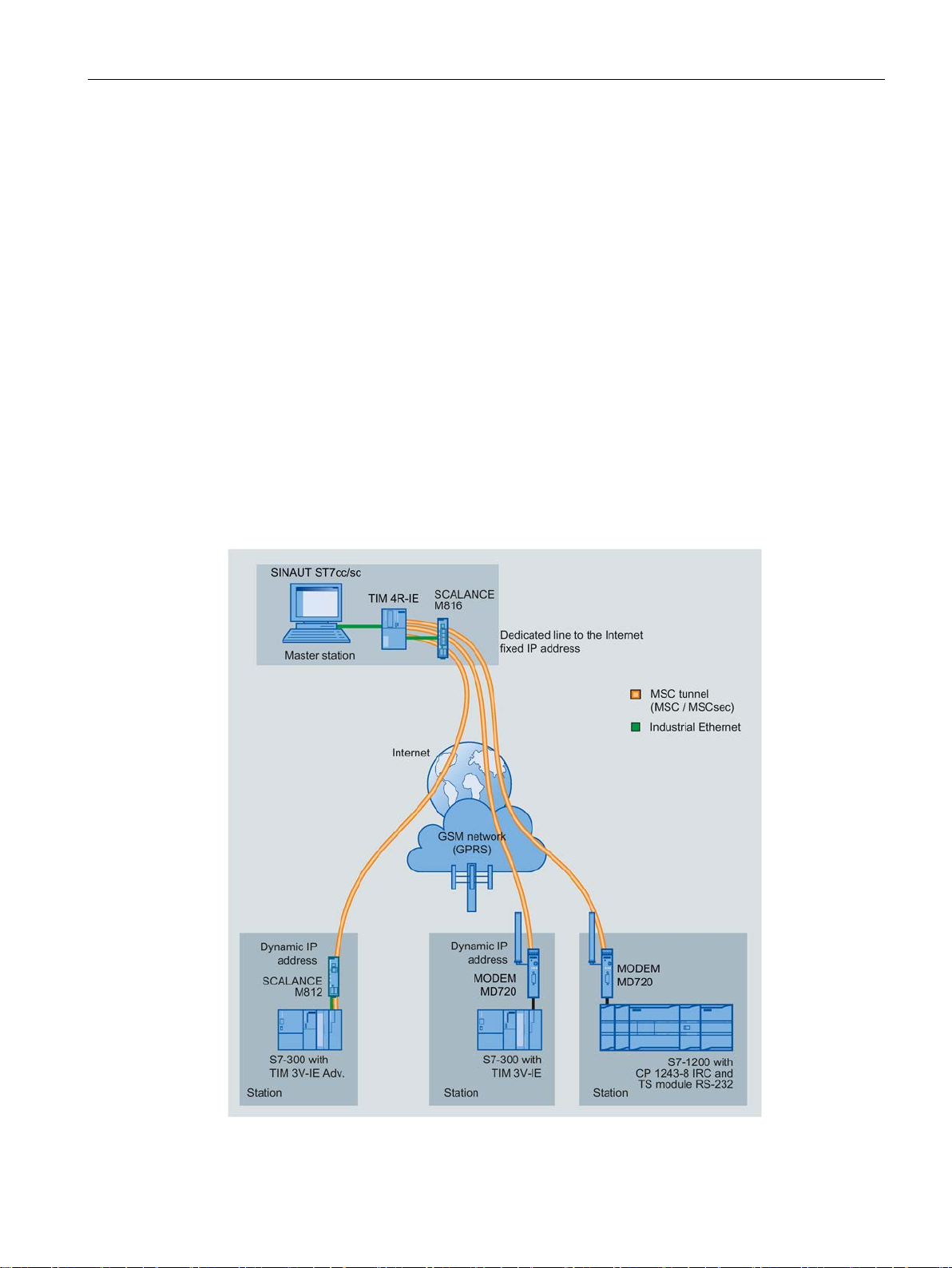
Telecontrol communication - MSC
1.9 Configuration examples
Below, you will find configuration examples for stations with a CP 1243-8 IRC.
In telecontrol communication the station communicates via the CP with a master station.
Communication can take place via various interfaces of the CP and via various network
types.
In the sample configuration shown, stations communicate with a master station TIM that in
turn is connected to a master station of the type SINAUT ST7sc:
● An S7-300 that only communicates via the Internet.
● An S7-300 that communicates via the mobile wireless network and the Internet.
● An S7-1200 with CP 1243-8 IRC that communicates via the mobile wireless network and
the Internet.
All three stations use the transport protocol MSC (or MSCsec).
Figure 1-1 Communication with the MSC protocol via mobile wireless and Internet
CP 1243-8 IRC
Operating Instructions, 02/2018, C79000-G8976-C385-03
25
Application and functions
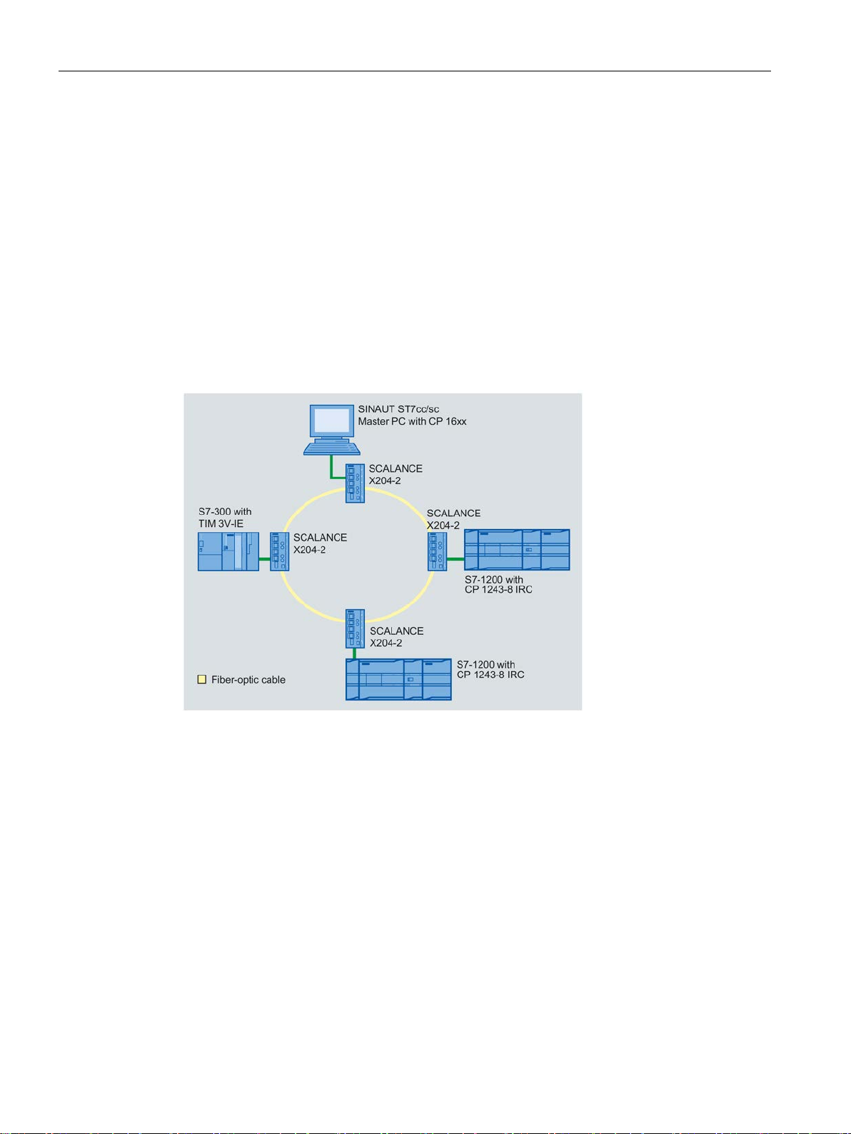
Inter-station communication between stations
Telecontrol communication - Ethernet
1.9 Configuration examples
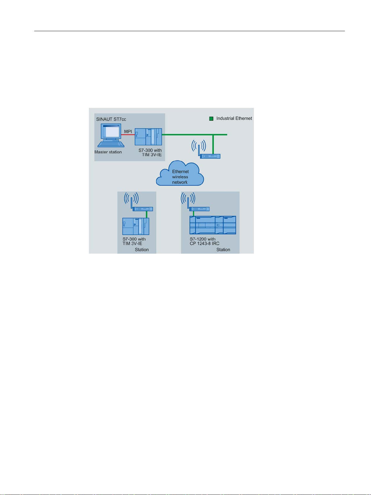
Inter-station communication is possible for stations connected to the same master station.
For the inter-station communication between stations, the master station forwards the
messages of the sending station to the receiving station.
In the sample configuration shown, an S7-300 and two S7-1200 stations communicate with a
master station SINAUT ST7cc/ST7sc.
The CPs are connected via their Ethernet interface.
The connection to the Ethernet network, in this example a fiber-optic cable, is implemented
using SCALANCE X switches. Copper cable is also possible as the medium.
Figure 1-2 Communication via an Ethernet network (optical medium)
CP 1243-8 IRC
26 Operating Instructions, 02/2018, C79000-G8976-C385-03
Application and functions
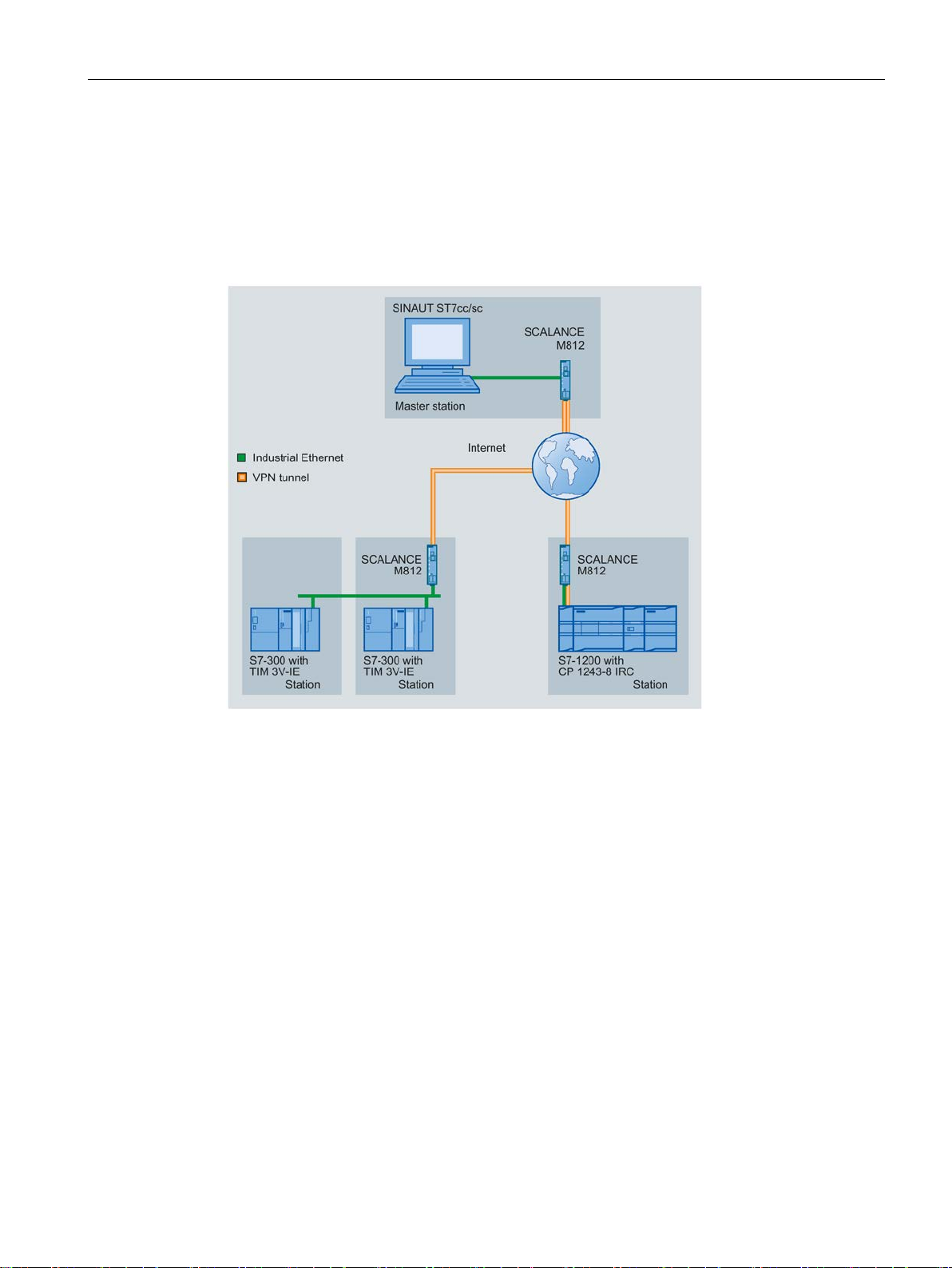
Telecontrol communication - Internet
1.9 Configuration examples
In the sample configuration shown, an S7-300 and two S7-1200 stations communicate with a
master station SINAUT ST7cc/ST7sc via the Internet.
The CPs are connected via their Ethernet interface.
VPN tunnels are established via the ADSL router SCALANCE M812.
Figure 1-3 Communication via the Internet with VPN tunnels
CP 1243-8 IRC
Operating Instructions, 02/2018, C79000-G8976-C385-03
27
Application and functions
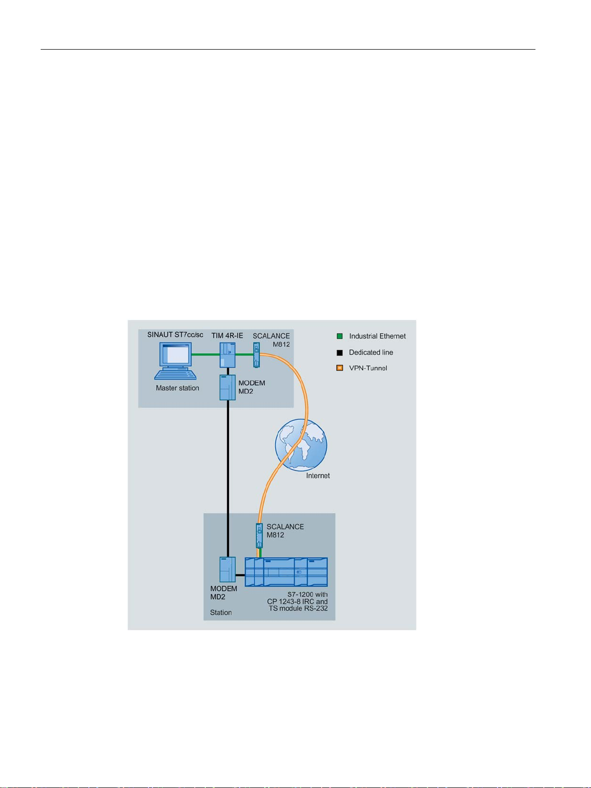
Telecontrol communication - redundant paths
1.9 Configuration examples
In this example an S7-1200 with a CP 1243-8 is connected to the master station via
redundant paths:
● One path via a dedicated line
● One path via the Internet
Other network combinations are possible.
As the master station TIM, a TIM 4R-IE is used here that uses the following interfaces:
● One Ethernet interface for connecting to the master station PC
● One Ethernet interface for connection to the Internet (via a SCALANCE M812 router)
● One serial interface for connection to the dedicated line modem MD2
The CP is connected via both interfaces:
● One Ethernet interface for connection to the Internet (via a SCALANCE M812 router)
● Serial interface with TS modules RS-232 for connection to the dedicated line
Figure 1-4 Communication of an S7-1200 via redundant paths
CP 1243-8 IRC
28 Operating Instructions, 02/2018, C79000-G8976-C385-03
Application and functions
Telecontrol communication - wireless network
1.9 Configuration examples
In this example, the S7 stations communicate with the master station via an IP-based private
wireless network. For this application, suitable IP-based wireless devices must be used.
The CPs are connected via their Ethernet interface. In this configuration as well, an Ethernet
network needs to be configured in STEP 7 V5.
Figure 1-5 Communication via an IP-based private wireless network
Communication via an analog wireless network with communication according to the RS-232
standard is also possible. In this case, the CP 1243-8 would need to be connected to the
wireless device via a TS module RS-232. In this configuration a dedicated line network
would need to be configured in STEP 7 V5.
CP 1243-8 IRC
Operating Instructions, 02/2018, C79000-G8976-C385-03
29
Application and functions
SMS messages and e-mails
SMS
E-mails
1.9 Configuration examples
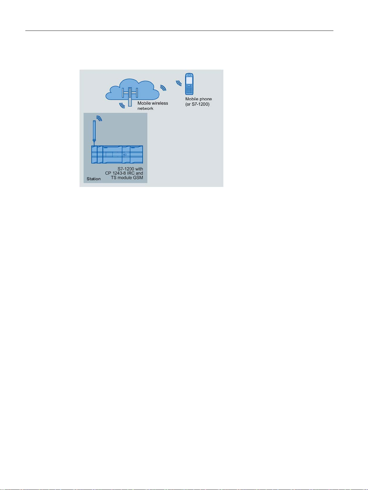
Figure 1-6 Sending messages by SMS from an S7-1200 station
The CP can send SMS messages to a mobile phone. SMS messages are generated and
sent due to events. You will find the description of the configuration in the following sections:
Data point configuration (Page 128)
Message configuration (Page 163)
The CP can send e-mails to a PC with an Internet connection or a mobile phone. The
mechanisms for this are as follows:
● E-mails that are generated by the telecontrol application.
E-mails are generated and sent due to events. You will find the description of the
configuration in the following sections:
Data point configuration (Page 128)
Message configuration (Page 163)
TheE-mail configuration (Page 110)
● E-mails sent as a result of calling the program block TMAIL_C.
You will find information on the blocks in the section Program blocks (Page 167). You will
find the description of the programming in the STEP 7 information system.
CP 1243-8 IRC
30 Operating Instructions, 02/2018, C79000-G8976-C385-03
 Loading...