


___________________
___________________
___________________
___________________
___________________
___________________
___________________
___________________
___________________
___________________
___________________
___________________
___________________
___________________
___________________
___________________
___________________
___________________
___________________
SIMATIC
S7
S7-200 SMART
System Manual
V2.3, 07/2017
A5E03822230
Preface
Product overview
1
Getting started
2
Installation
3
PLC concepts
4
Programming concepts
5
PLC device configuration
6
Program instructions
7
Communication
8
Libraries
9
Debugging and
troubleshooting
10
PID loops and tuning
11
Open loop motion control
12
Technical specifications
A
Calculating a power budget
B
Error codes
C
Special memory (SM) and
system symbol names
D
References
E
Ordering information
F
-AF
Siemens AG
Division Digital Factory
Postfach 48 48
90026 NÜRNBERG
GERMANY
A5E03822230-AF
Ⓟ
Copyright © Siemens AG 2017.
All rights reserved
Legal information
Warning notice system
DANGER
indicates that death or severe personal injury will result if proper precautions are not taken.
WARNING
indicates that death or severe personal injury may result if proper precautions are not taken.
CAUTION
indicates that minor personal injury can result if proper precautions are not taken.
NOTICE
indicates that property damage can result if proper precautions are not taken.
Qualified Personnel
personnel qualified
Proper use of Siemens products
WARNING
Siemens products may only be used for the applications described in the catalog and in the relevant technical
maintenance are required to ensure that the products operate safely and without any problems. The permissible
ambient conditions must be complied with. The information in the relevant documentation must be observed.
Trademarks
Disclaimer of Liability
This manual contains notices you have to observe in order to ensure your personal safety, as well as to prevent
damage to property. The notices referring to your personal safety are highlighted in the manual by a safety alert
symbol, notices referring only to property damage have no safety alert symbol. These notices shown below are
graded according to the degree of danger.
If more than one degree of danger is present, the warning notice representing the highest degree of danger will
be used. A notice warning of injury to persons with a safety alert symbol may also include a warning relating to
property damage.
The product/system described in this documentation may be operated only by
task in accordance with the relevant documentation, in particular its warning notices and safety instructions.
Qualified personnel are those who, based on their training and experience, are capable of identifying risks and
avoiding potential hazards when working with these products/systems.
Note the following:
documentation. If products and components from other manufacturers are used, these must be recommended
or approved by Siemens. Proper transport, storage, installation, assembly, commissioning, operation and
All names identified by ® are registered trademarks of Siemens AG. The remaining trademarks in this publication
may be trademarks whose use by third parties for their own purposes could violate the rights of the owner.
We have reviewed the contents of this publication to ensure consistency with the hardware and software
described. Since variance cannot be precluded entirely, we cannot guarantee full consistency. However, the
information in this publication is reviewed regularly and any necessary corrections are included in subsequent
editions.
for the specific
06/2017 Subject to change

Preface
Purpose of the manual
Required basic knowledge
Scope of the manual
Certification, CE label and other standards
Service and support
The S7-200 SMART series is a line of micro-programmable logic controllers (Micro PLCs)
that can control a variety of automation applications. Compact design, low cost, and a
powerful instruction set make the S7-200 SMART a perfect solution for controlling small
applications. The wide variety of S7-200 SMART models and the Windows-based
programming tool give you the flexibility you need to solve your automation problems.
This manual provides information about installing and programming the S7-200 SMART
CPUs and is designed for engineers, programmers, installers, and electricians who have a
general knowledge of programmable logic controllers.
To understand this manual, it is necessary to have a general knowledge of automation and
programmable logic controllers.
This manual describes the following products:
● STEP 7-Micro/WIN SMART V2.3
● S7-200 SMART CPU firmware release V2.3
For a complete list of the S7-200 SMART products and article numbers described in this
manual, see Technical Specifications (Page 679).
Refer to the technical specifications for more information.
In addition to our documentation, we offer our technical expertise on the Internet on the
customer support web site (http://www.siemens.com/automation/).
Contact your Siemens distributor or sales office for assistance in answering any technical
questions, for training, or for ordering S7 products. Because your sales representatives are
technically trained and have the most specific knowledge about your operations, process
and industry, as well as about the individual Siemens products that you are using, they can
provide the fastest and most efficient answers to any problems you might encounter.
S7-200 SMART
System Manual, V2.3, 07/2017, A5E03822230-AF
3

Preface
Security information
Siemens provides products and solutions with industrial security functions that support the
secure operation of plants, systems, machines and networks.
In order to protect plants, systems, machines and networks against cyber threats, it is
necessary to implement – and continuously maintain – a holistic, state-of-the-art industrial
security concept. Siemens’ products and solutions only form one element of such a concept.
Customer is responsible to prevent unauthorized access to its plants, systems, machines
and networks. Systems, machines and components should only be connected to the
enterprise network or the internet if and to the extent necessary and with appropriate security
measures (e.g. use of firewalls and network segmentation) in place.
Additionally, Siemens’ guidance on appropriate security measures should be taken into
account. For more information about industrial security, please visit
(http://www.siemens.com/industrialsecurity).
Siemens’ products and solutions undergo continuous development to make them more
secure. Siemens strongly recommends to apply product updates as soon as available and to
always use the latest product versions. Use of product versions that are no longer supported,
and failure to apply latest updates may increase customer’s exposure to cyber threats.
To stay informed about product updates, subscribe to the Siemens Industrial Security RSS
Feed under (http://www.siemens.com/industrialsecurity).
S7-200 SMART
4 System Manual, V2.3, 07/2017, A5E03822230-AF

Table of contents
Preface ................................................................................................................................................... 3
1 Product overview .................................................................................................................................. 17
2 Getting started ...................................................................................................................................... 31
3 Installation ............................................................................................................................................ 47
1.1 S7-200 SMART CPU .............................................................................................................. 18
1.2 New features ........................................................................................................................... 21
1.3 CPU feature differences.......................................................................................................... 23
1.4 S7-200 SMART expansion modules ....................................................................................... 26
1.5 HMI devices for S7-200 SMART ............................................................................................. 27
1.6 Communications options ........................................................................................................ 28
1.7 Programming software ............................................................................................................ 29
2.1 Connecting to the CPU ........................................................................................................... 31
2.1.1 Configuring the CPU for communication ................................................................................ 32
2.1.1.1 Overview ................................................................................................................................. 32
2.1.1.2 Establishing the Ethernet hardware communication connection ............................................ 33
2.1.1.3 Setting up Ethernet communication with the CPU .................................................................. 34
2.1.1.4 Establishing the RS485 hardware communication connection............................................... 36
2.1.1.5 Setting up RS485 communication with the CPU .................................................................... 37
2.2 Creating the sample program ................................................................................................. 39
2.2.1 Network 1: Starting the timer .................................................................................................. 40
2.2.2 Network 2: Turning the output on ........................................................................................... 41
2.2.3 Network 3: Resetting the timer ............................................................................................... 42
2.2.4 Setting the CPU type and version for your project ................................................................. 43
2.2.5 Saving the sample project ...................................................................................................... 44
2.3 Downloading the sample program .......................................................................................... 45
2.4 Changing the operating mode of the CPU .............................................................................. 46
3.1 Guidelines for installing S7-200 SMART devices ................................................................... 47
3.2 Power budget .......................................................................................................................... 49
3.3 Installation and removal procedures ....................................................................................... 51
3.3.1 Mounting dimensions for the S7-200 SMART devices ........................................................... 51
3.3.2 Installing and removing the CPU ............................................................................................ 52
3.3.3 Installing and removing a signal board or battery board ......................................................... 55
3.3.4 Removing and reinstalling the terminal block connector ........................................................ 57
3.3.5 Installing and removing an expansion module ....................................................................... 58
3.3.6 Installing and removing the expansion cable .......................................................................... 60
3.4 Wiring guidelines ..................................................................................................................... 62
S7-200 SMART
System Manual, V2.3, 07/2017, A5E03822230-AF
5

Table of contents
4 PLC concepts ....................................................................................................................................... 69
5 Programming concepts ........................................................................................................................ 103
4.1 Execution of the control logic ................................................................................................. 69
4.1.1 Reading the inputs and writing to the outputs ........................................................................ 71
4.1.2 Immediately reading or writing the I/O ................................................................................... 71
4.1.3 Executing the user program ................................................................................................... 72
4.2 Accessing data ....................................................................................................................... 74
4.2.1 Accessing memory areas ....................................................................................................... 75
4.2.2 Format for Real numbers ....................................................................................................... 82
4.2.3 Format for strings ................................................................................................................... 82
4.2.4 Assigning a constant value for instructions ............................................................................ 83
4.2.5 Addressing the local and expansion I/O ................................................................................ 83
4.2.6 Using pointers for indirect addressing.................................................................................... 84
4.2.7 Pointer examples ................................................................................................................... 87
4.3 Saving and restoring data ...................................................................................................... 89
4.3.1 Downloading project components .......................................................................................... 89
4.3.2 Uploading project components .............................................................................................. 92
4.3.3 Types of storage .................................................................................................................... 93
4.3.4 Using a memory card ............................................................................................................. 94
4.3.5 Inserting a memory card in a standard CPU .......................................................................... 96
4.3.6 Transferring your program with a memory card ..................................................................... 97
4.3.7 Restoring data after power on ................................................................................................ 99
4.4 Changing the operating mode of the CPU ........................................................................... 100
4.5 Status LEDs ......................................................................................................................... 101
5.1 Guidelines for designing a PLC system ............................................................................... 103
5.2 Elements of the user program .............................................................................................. 105
5.3 Creating your user program ................................................................................................. 108
5.3.1 Earlier versions of STEP 7-Micro/WIN projects ................................................................... 108
5.3.2 Using STEP 7-Micro/WIN SMART user interface ................................................................ 110
5.3.3 Using STEP 7-Micro/WIN SMART to create your programs ............................................... 111
5.3.4 Using wizards to help you create your control program....................................................... 112
5.3.5 Features of the LAD editor ................................................................................................... 113
5.3.6 Features of the FBD editor ................................................................................................... 114
5.3.7 Features of the STL editor ................................................................................................... 114
5.4 Data block (DB) editor .......................................................................................................... 115
5.5 Symbol table ........................................................................................................................ 118
5.6 Variable table ....................................................................................................................... 121
5.7 PLC error reaction ................................................................................................................ 127
5.7.1 Non-fatal errors and I/O errors ............................................................................................. 128
5.7.2 Fatal errors ........................................................................................................................... 129
5.8 Program edit in RUN mode .................................................................................................. 130
5.9 Features for debugging your program ................................................................................. 132
S7-200 SMART
6 System Manual, V2.3, 07/2017, A5E03822230-AF

Table of contents
6 PLC device configuration .................................................................................................................... 133
7 Program instructions ........................................................................................................................... 169
6.1 Configuring the operation of the PLC system ....................................................................... 133
6.1.1 System block ......................................................................................................................... 133
6.1.2 Configuring communication .................................................................................................. 135
6.1.3 Configuring the digital inputs ................................................................................................ 138
6.1.4 Configuring the digital outputs .............................................................................................. 140
6.1.5 Configuring the retentive ranges ........................................................................................... 141
6.1.6 Configuring system security .................................................................................................. 143
6.1.7 Configuring the startup options ............................................................................................. 147
6.1.8 Configuring the analog inputs ............................................................................................... 148
6.1.9 Reference to the analog inputs technical specifications ....................................................... 150
6.1.10 Configuring the analog outputs ............................................................................................. 151
6.1.11 Reference to the analog outputs technical specifications..................................................... 152
6.1.12 Configuring the RTD analog inputs ....................................................................................... 153
6.1.13 Configuring the TC analog inputs ......................................................................................... 158
6.1.14 Configuring the RS485/RS232 CM01 communications signal board ................................... 162
6.1.15 Configuring the BA01 battery signal board ........................................................................... 163
6.1.16 Clearing PLC memory........................................................................................................... 164
6.1.17 Creating a reset-to-factory-defaults memory card ................................................................ 167
6.2 High-speed I/O ...................................................................................................................... 168
7.1 Bit logic ................................................................................................................................. 169
7.1.1 Standard inputs ..................................................................................................................... 169
7.1.2 Immediate inputs ................................................................................................................... 171
7.1.3 Logic stack overview ............................................................................................................. 172
7.1.4 STL logic stack instructions .................................................................................................. 174
7.1.5 NOT....................................................................................................................................... 176
7.1.6 Positive and negative transition detectors ............................................................................ 177
7.1.7 Coils: output and output immediate instructions ................................................................... 178
7.1.8 Set, reset, set immediate, and reset immediate functions .................................................... 179
7.1.9 Set and reset dominant bistable ........................................................................................... 180
7.1.10 NOP (No operation) instruction ............................................................................................. 181
7.1.11 Bit logic input examples ........................................................................................................ 182
7.1.12 Bit logic output examples ...................................................................................................... 183
7.2 Clock ..................................................................................................................................... 185
7.2.1 Read and set real-time clock ................................................................................................ 185
7.2.2 Read and set real-time clock extended ................................................................................ 187
7.3 Communication ..................................................................................................................... 191
7.3.1 GET and PUT (Ethernet) ...................................................................................................... 191
7.3.2 Transmit and receive (Freeport on RS485/RS232) .............................................................. 199
7.3.3 Get port address and set port address (PPI protocol on RS485/RS232) ............................. 213
7.3.4 Get IP address and set IP address (Ethernet) ...................................................................... 214
7.3.5 Open user communication .................................................................................................... 217
7.3.5.1 OUC instructions ................................................................................................................... 217
7.3.5.2 OUC instruction error codes ................................................................................................. 228
7.4 Compare ............................................................................................................................... 230
7.4.1 Compare number values ...................................................................................................... 230
7.4.2 Compare character strings ................................................................................................... 234
S7-200 SMART
System Manual, V2.3, 07/2017, A5E03822230-AF
7

Table of contents
7.5 Convert ................................................................................................................................. 236
7.5.1 Standard conversion instructions ......................................................................................... 236
7.5.2 ASCII character array conversion ........................................................................................ 240
7.5.3 Number value to ASCII string conversion ............................................................................ 245
7.5.4 ASCII sub-string to number value conversion ..................................................................... 249
7.5.5 Encode and decode ............................................................................................................. 252
7.6 Counters ............................................................................................................................... 253
7.6.1 Counter instructions ............................................................................................................. 253
7.6.2 High-speed counter instructions .......................................................................................... 257
7.6.3 High-speed counter summary .............................................................................................. 260
7.6.4 Noise reduction for high-speed inputs ................................................................................. 261
7.6.5 High-speed counter programming ....................................................................................... 264
7.6.6 Example initialization sequences for high-speed counters .................................................. 277
7.7 Pulse output ......................................................................................................................... 285
7.7.1 Pulse output instruction (PLS) ............................................................................................. 285
7.7.2 Pulse train output (PTO) ...................................................................................................... 287
7.7.3 Pulse width modulation (PWM) ............................................................................................ 289
7.7.4 Using SM locations to configure and control the PTO/PWM operation ............................... 290
7.7.5 Calculating the profile table values ...................................................................................... 294
7.8 Math ..................................................................................................................................... 297
7.8.1 Add, subtract, multiply, and divide ....................................................................................... 297
7.8.2 Multiply integer to double integer and divide integer with remainder................................... 300
7.8.3 Trigonometry, natural logarithm/exponential, and square root ............................................ 302
7.8.4 Increment and decrement .................................................................................................... 305
7.9 PID ....................................................................................................................................... 307
7.9.1 Using the PID wizard ........................................................................................................... 308
7.9.2 PID algorithm ....................................................................................................................... 313
7.9.3 Converting and normalizing the loop inputs ......................................................................... 317
7.9.4 Converting the loop output to a scaled integer value........................................................... 318
7.9.5 Forward- or reverse-acting loops ......................................................................................... 319
7.10 Interrupt ................................................................................................................................ 322
7.10.1 Interrupt instructions ............................................................................................................ 322
7.10.2 Interrupt routine overview and CPU model event support ................................................... 324
7.10.3 Interrupt programming guidelines ........................................................................................ 326
7.10.4 Types of interrupt events that the S7-200 SMART CPU supports ...................................... 328
7.10.5
Interrupt priority, queuing, and example program ................................................................ 330
7.11 Logical operations ................................................................................................................ 335
7.11.1 Invert .................................................................................................................................... 335
7.11.2 AND, OR, and exclusive OR ................................................................................................ 336
7.12 Move .................................................................................................................................... 338
7.12.1 Move byte, word, double word, or real ................................................................................. 338
7.12.2 Block move ........................................................................................................................... 339
7.12.3 Swap bytes ........................................................................................................................... 340
7.12.4 Move byte immediate (read and write) ................................................................................ 341
7.13 Program control.................................................................................................................... 342
7.13.1 FOR-NEXT loop ................................................................................................................... 342
7.13.2 JMP (jump to label) .............................................................................................................. 344
7.13.3 SCR (sequence control relay) .............................................................................................. 345
S7-200 SMART
8 System Manual, V2.3, 07/2017, A5E03822230-AF

Table of contents
8 Communication ................................................................................................................................... 395
7.13.4 END, STOP, and WDR (watchdog timer reset) .................................................................... 354
7.13.5 GET_ERROR (Get non-fatal error code) .............................................................................. 356
7.14 Shift and rotate ...................................................................................................................... 357
7.14.1 Shift and rotate ...................................................................................................................... 357
7.14.2 Shift register bit ..................................................................................................................... 360
7.15 String ..................................................................................................................................... 362
7.15.1 String (Get length, copy, and concatenate) .......................................................................... 362
7.15.2 Copy substring from string .................................................................................................... 364
7.15.3 Find string and first character within string ........................................................................... 365
7.16 Table ..................................................................................................................................... 368
7.16.1 Add to table ........................................................................................................................... 368
7.16.2 First-in-first-out and last-in-first-out ....................................................................................... 370
7.16.3 Memory fill ............................................................................................................................. 372
7.16.4 Table find .............................................................................................................................. 373
7.17 Timer ..................................................................................................................................... 377
7.17.1 Timer instructions .................................................................................................................. 377
7.17.2 Timer programming tips and examples ................................................................................ 380
7.17.3 Interval timers ....................................................................................................................... 386
7.18 Subroutine ............................................................................................................................. 388
7.18.1 CALL (subroutine) and RET (conditional return) .................................................................. 388
8.1 CPU communication connections ......................................................................................... 396
8.2 CPU communication ports .................................................................................................... 397
8.3 HMIs and communication drivers ......................................................................................... 398
8.4 Ethernet ................................................................................................................................ 400
8.4.1 Overview ............................................................................................................................... 400
8.4.2 Local/partner connection ...................................................................................................... 400
8.4.3 Sample Ethernet network configurations .............................................................................. 401
8.4.4 Assigning Internet Protocol (IP) addresses .......................................................................... 402
8.4.4.1 Assigning IP addresses to programming and network devices ............................................ 402
8.4.4.2 Configuring or changing an IP address for a CPU or device in your project ........................ 404
8.4.4.3 Searching for CPUs and devices on your Ethernet network ................................................ 412
8.4.5 Locating the Ethernet (MAC) address on the CPU ............................................................... 413
8.4.6 HMI-to-CPU communication ................................................................................................. 415
8.4.7 Open user communication .................................................................................................... 417
8.4.7.1 Protocols ............................................................................................................................... 417
8.4.7.2 Connections .......................................................................................................................... 418
8.4.7.3 Ports and TSAPs .................................................................................................................. 419
8.5 PROFIBUS ............................................................................................................................ 421
8.5.1 EM DP01 PROFIBUS DP module ........................................................................................ 423
8.5.1.1 Distributed Peripheral (DP) standard communications ......................................................... 423
8.5.1.2 Using the EM DP01 to connect an S7-200 SMART as a DP device .................................... 424
8.5.1.3 Configuring the EM DP01 ..................................................................................................... 426
8.5.1.4 Data consistency ................................................................................................................... 427
8.5.1.5 Supported configurations ...................................................................................................... 428
8.5.1.6 Installing the EM DP01 GSD file ........................................................................................... 429
8.5.1.7 Configuring the EM DP01 I/O ............................................................................................... 431
S7-200 SMART
System Manual, V2.3, 07/2017, A5E03822230-AF
9

Table of contents
9 Libraries ............................................................................................................................................... 471
8.5.1.8 Example of V memory and I/O address area ....................................................................... 433
8.5.1.9 User program considerations ............................................................................................... 435
8.5.1.10 LED status indicators for the EM DP01 PROFIBUS DP ...................................................... 437
8.5.1.11 Using HMIs and S7-CPUs with the EM DP01 ..................................................................... 439
8.5.1.12 Device database file: GSD ................................................................................................... 440
8.5.1.13 PROFIBUS DP communications to a CPU example program ............................................. 444
8.5.1.14 Reference to the EM DP01 PROFIBUS DP module technical specifications ..................... 446
8.6 RS485 .................................................................................................................................. 446
8.6.1 PPI protocol .......................................................................................................................... 447
8.6.2 Baud rate and network address ........................................................................................... 448
8.6.2.1 Definition of baud rate and network address ....................................................................... 448
8.6.2.2 Setting the baud rate and network address for the S7-200 SMART CPU ........................... 449
8.6.3 Sample RS485 network configurations ................................................................................ 451
8.6.3.1 Single-master PPI networks ................................................................................................. 451
8.6.3.2 Multi-master and multi-slave PPI networks .......................................................................... 451
8.6.4 Assigning RS485 addresses ................................................................................................ 452
8.6.4.1 Configuring or changing an RS485 address for a CPU or device in your project ............... 452
8.6.4.2 Searching for CPUs and devices on your RS485 network .................................................. 457
8.6.5 Building your network ........................................................................................................... 458
8.6.5.1 General guidelines ............................................................................................................... 458
8.6.5.2 Determining the distances, transmission rates, and cable lengths for your network ........... 459
8.6.5.3 Repeaters on the network .................................................................................................... 459
8.6.5.4 Specifications for RS485 cable ............................................................................................ 460
8.6.5.5 Connector pin assignments ................................................................................................. 460
8.6.5.6 Biasing and terminating the network cable .......................................................................... 462
8.6.5.7 Biasing and terminating the CM01 signal board .................................................................. 463
8.6.5.8 Using HMI devices on your RS485 network ........................................................................ 464
8.6.6 Freeport mode...................................................................................................................... 465
8.6.6.1 Creating user-defined protocols with Freeport mode........................................................... 465
8.6.6.2 Using the RS232/PPI Multi-Master cable and Freeport mode with RS232 devices ............ 468
8.7 RS232 .................................................................................................................................. 470
9.1 Library types (Siemens and user-defined) ........................................................................... 471
9.2 Overview of Modbus communication ................................................................................... 473
9.2.1 Modbus addressing .............................................................................................................. 473
9.2.2 Modbus read and write functions ......................................................................................... 475
9.3 Modbus RTU library ............................................................................................................. 476
9.3.1 Modbus communication overview ........................................................................................ 476
9.3.1.1 Modbus RTU library features ............................................................................................... 476
9.3.1.2 Requirements for using Modbus instructions ....................................................................... 477
9.3.1.3 Initialization and execution time for Modbus protocol .......................................................... 478
9.3.2 Modbus RTU master ............................................................................................................ 479
9.3.2.1 Using the Modbus RTU master instructions ........................................................................ 479
9.3.2.2 MBUS_CTRL / MB_CTRL2 instruction (initialize master) .................................................... 481
9.3.2.3 MBUS_MSG / MB_MSG2 instruction ................................................................................... 483
9.3.2.4 Modbus RTU master execution error codes ........................................................................ 487
9.3.3 Modbus RTU slave .............................................................................................................. 489
9.3.3.1 Using the Modbus RTU slave instructions ........................................................................... 489
9.3.3.2 MBUS_INIT instruction (initialize slave) ............................................................................... 491
S7-200 SMART
10 System Manual, V2.3, 07/2017, A5E03822230-AF

Table of contents
10 Debugging and troubleshooting ........................................................................................................... 565
9.3.3.3 MBUS_SLAVE instruction ..................................................................................................... 492
9.3.3.4 Modbus RTU slave execution error codes............................................................................ 493
9.3.4 Modbus RTU master example program................................................................................ 494
9.3.5 Modbus RTU advanced user information ............................................................................. 496
9.4 Open user communication library ......................................................................................... 498
9.4.1 Parameters common to the OUC library instructions ........................................................... 499
9.4.2 Open user communication library instructions ...................................................................... 501
9.4.2.1 TCP_CONNECT instruction .................................................................................................. 501
9.4.2.2 ISO_CONNECT instruction ................................................................................................... 504
9.4.2.3 UDP_CONNECT instruction ................................................................................................. 508
9.4.2.4 TCP_SEND instruction.......................................................................................................... 510
9.4.2.5 TCP_RECV instruction.......................................................................................................... 513
9.4.2.6 UDP_SEND instruction ......................................................................................................... 516
9.4.2.7 UDP_RECV instruction ......................................................................................................... 519
9.4.2.8 DISCONNECT instruction ..................................................................................................... 522
9.4.3 Open user communication library instruction error codes .................................................... 524
9.4.4 Open user communication library example .......................................................................... 525
9.4.4.1 Active partner (client) ............................................................................................................ 526
9.4.4.2 CheckErrors subroutine ........................................................................................................ 535
9.4.4.3 Active partner symbol table .................................................................................................. 536
9.4.4.4 Passive partner (server)........................................................................................................ 537
9.4.4.5 CheckErrors subroutine ........................................................................................................ 543
9.4.4.6 Passive partner symbol table ................................................................................................ 544
9.5 USS library ............................................................................................................................ 545
9.5.1 USS communication overview .............................................................................................. 545
9.5.1.1 USS protocol overview.......................................................................................................... 545
9.5.1.2 Requirements for using the USS protocol ............................................................................ 546
9.5.1.3 Calculating the time required for communicating with the drive ........................................... 547
9.5.2 USS program instructions ..................................................................................................... 548
9.5.2.1 Using the USS protocol instructions ..................................................................................... 548
9.5.2.2 USS_INIT instruction ............................................................................................................. 549
9.5.2.3 USS_CTRL instruction .......................................................................................................... 551
9.5.2.4 USS_RPM_x instruction ........................................................................................................ 554
9.5.2.5 USS_WPM_x instruction ....................................................................................................... 557
9.5.2.6 USS protocol execution error codes ..................................................................................... 560
9.5.2.7 USS protocol example program ............................................................................................ 561
9.6 Creating a user-defined library of instructions ................................................................
...... 563
10.1 Debugging your program ...................................................................................................... 565
10.1.1 Bookmark functions .............................................................................................................. 565
10.1.2 Cross reference table............................................................................................................ 566
10.2 Displaying program status .................................................................................................... 568
10.2.1 Displaying status in the program editor ................................................................................ 568
10.2.2 Configuring the STL status options ....................................................................................... 571
10.3 Using a status chart to monitor your program ...................................................................... 572
10.4 Forcing specific values.......................................................................................................... 574
10.5 Writing and forcing outputs in STOP mode .......................................................................... 575
S7-200 SMART
System Manual, V2.3, 07/2017, A5E03822230-AF
11

Table of contents
11 PID loops and tuning ............................................................................................................................ 581
12 Open loop motion control ..................................................................................................................... 595
10.6 How to execute a limited number of scans .......................................................................... 576
10.7 Hardware troubleshooting guide .......................................................................................... 578
11.1 PID loop definition table ....................................................................................................... 582
11.2 Prerequisites ........................................................................................................................ 586
11.3 Auto-hysteresis and auto-deviation...................................................................................... 586
11.4 Auto-tune sequence ............................................................................................................. 587
11.5 Exception conditions ............................................................................................................ 589
11.6 Notes concerning PV out-of-range (result code 3) .............................................................. 590
11.7 PID Tune control panel ........................................................................................................ 590
12.1 Using the PWM output ......................................................................................................... 596
12.1.1 Configuring the PWM output ................................................................................................ 596
12.1.2 PWMx_RUN subroutine ....................................................................................................... 598
12.2 Using motion control ............................................................................................................ 599
12.2.1 Maximum and start/stop speeds .......................................................................................... 599
12.2.2 Entering the acceleration and deceleration times ................................................................ 600
12.2.3 Configuring the motion profiles ............................................................................................ 601
12.3 Features of motion control ................................................................................................... 604
12.4 Programming an Axis of Motion ........................................................................................... 606
12.5 Configuring an Axis of Motion .............................................................................................. 607
12.6 Subroutines created by the Motion wizard for the Axis of Motion ........................................ 620
12.6.1 Guidelines for using the Motion subroutines ........................................................................ 621
12.6.2 AXISx_CTRL subroutine ...................................................................................................... 622
12.6.3 AXISx_MAN subroutine ....................................................................................................... 623
12.6.4 AXISx_GOTO subroutine ..................................................................................................... 625
12.6.5 AXISx_RUN subroutine ........................................................................................................ 626
12.6.6 AXISx_RSEEK subroutine ................................................................................................... 627
12.6.7 AXISx_LDOFF subroutine .................................................................................................... 628
12.6.8 AXISx_LDPOS subroutine ................................................................................................... 629
12.6.9 AXISx_SRATE subroutine ................................................................................................... 630
12.6.10 AXISx_DIS subroutine ......................................................................................................... 631
12.6.11 AXISx_CFG subroutine ........................................................................................................ 632
12.6.12 AXISx_CACHE subroutine ................................................................................................... 633
12.6.13 AXISx_RDPOS subroutine ................................................................................................... 634
12.6.14 AXISx_ABSPOS subroutine ................................................................................................. 635
12.7 Using the AXISx_ABSPOS subroutine to read the absolute position from a SINAMICS
servo drive ............................................................................................................................ 637
12.7.1 AXISx_ABSPOS and AXISx_LDPOS subroutines usage examples ................................... 637
12.7.2 Interconnections ................................................................................................................... 638
12.7.3 Commissioning..................................................................................................................... 639
12.7.3.1 Control mode ........................................................................................................................ 639
12.7.3.2 Setpoint pulse input channel ................................................................................................ 639
12.7.3.3 Setpoint pulse train input format .......................................................................................... 639
S7-200 SMART
12 System Manual, V2.3, 07/2017, A5E03822230-AF

Table of contents
A Technical specifications ...................................................................................................................... 679
12.7.3.4 Common engineering units basis ......................................................................................... 639
12.7.4 Important facts to know ......................................................................................................... 642
12.8 Axis of Motion example programs ........................................................................................ 643
12.8.1 Axis of Motion simple relative move (cut-to-length application) example ............................. 643
12.8.2 Axis of Motion AXISx_CTRL, AXISx_RUN, AXISx_SEEK, and AXISx_MAN example ........ 645
12.9 Monitoring the Axis of Motion ............................................................................................... 649
12.9.1 Displaying and controlling the operation of the Axis of Motion ............................................. 651
12.9.2 Displaying and modifying the configuration of the Axis of Motion ........................................ 656
12.9.3 Displaying the profile configuration for the Axis of Motion .................................................... 656
12.9.4 Error codes for the Axis of Motion (WORD at SMW620, SMW670, or SMW720)................ 658
12.9.5 Error codes for the Motion instruction (seven LS bits of SMB634, SMB684, or
SMB734) ............................................................................................................................... 659
12.10 Advanced topics .................................................................................................................... 661
12.10.1 Understanding the configuration/profile table for the Axis of Motion .................................... 661
12.10.2 Special memory (SM) locations for the Axis of Motion ......................................................... 670
12.11 Understanding the RP Seek modes of the Axis of Motion .................................................... 673
12.11.1 Selecting the work zone location to eliminate backlash ....................................................... 678
A.1 General specifications........................................................................................................... 679
A.1.1 General technical specifications ........................................................................................... 679
A.2 S7-200 SMART CPUs .......................................................................................................... 685
A.2.1 CPU ST20, CPU SR20, and CPU CR20s ............................................................................ 685
A.2.1.1 General specifications and features ..................................................................................... 685
A.2.1.2 Digital inputs and outputs ..................................................................................................... 689
A.2.1.3 Wiring diagrams .................................................................................................................... 692
A.2.2 CPU ST30, CPU SR30, and CPU CR30s ............................................................................ 695
A.2.2.1 General specifications and features ..................................................................................... 695
A.2.2.2 Digital inputs and outputs ..................................................................................................... 698
A.2.2.3 Wiring diagrams .................................................................................................................... 701
A.2.3 CPU ST40, CPU SR40, and CPU CR40s ............................................................................ 704
A.2.3.1 General specifications and features ..................................................................................... 704
A.2.3.2 Digital inputs and outputs ..................................................................................................... 708
A.2.3.3 Wiring diagrams .................................................................................................................... 711
A.2.4 CPU ST60, CPU SR60, and CPU CR60s ............................................................................ 714
A.2.4.1 General specifications and features ..................................................................................... 714
A.2.4.2 Digital inputs and outputs ..................................................................................................... 718
A.2.4.3 Wiring diagrams .................................................................................................................... 721
A.2.5 Wiring diagrams for sink and source input, and relay output................................................ 724
A.3 Digital inputs and outputs expansion modules (EMs) ........................................................... 725
A.3.1 EM DE08 and EM DE16 digital input specifications ............................................................. 725
A.3.2 EM DT08, EM DR08, EM QR16, and EM QT16 digital output specifications ...................... 727
A.3.3 EM DT16, EM DR16, EM DT32, and EM DR32 digital input/output specifications .............. 732
A.4 Analog inputs and outputs expansion modules (EMs) ......................................................... 738
A.4.1 EM AE04 and EM AE08 analog input specifications ............................................................ 738
A.4.2 EM AQ02 and EM AQ04 analog output module specifications ............................................ 741
A.4.3 EM AM03 and EM AM06 analog input/output module specifications ................................... 744
A.4.4 Step response of the analog inputs ...................................................................................... 748
A.4.5 Sample time and update times for the analog inputs ........................................................... 749
S7-200 SMART
System Manual, V2.3, 07/2017, A5E03822230-AF
13

Table of contents
B Calculating a power budget .................................................................................................................. 787
C Error codes .......................................................................................................................................... 791
A.4.6 Measurement ranges of the analog inputs for voltage and current (SB and EM) ............... 749
A.4.7 Measurement ranges of the analog outputs for voltage and current (SB and EM) ............. 750
A.5 Thermocouple and RTD expansion modules (EMs) ............................................................ 752
A.5.1 Thermocouple expansion modules (EMs) ........................................................................... 752
A.5.1.1 EM AT04 thermocouple specifications ................................................................................ 752
A.5.2 RTD expansion modules (EMs) ........................................................................................... 758
A.6 Digital signal boards ............................................................................................................. 763
A.6.1 SB DT04 digital input/output specifications ......................................................................... 763
A.7 Analog signal boards ........................................................................................................... 767
A.7.1 SB AE01 analog input specifications ................................................................................... 767
A.7.2 SB AQ01 analog output specifications ................................................................................ 769
A.8 RS485/RS232 signal boards ................................................................................................ 771
A.8.1 SB RS485/RS232 specifications.......................................................................................... 771
A.9 Battery board signal boards (SBs) ....................................................................................... 773
A.9.1 SB BA01 Battery board ........................................................................................................ 773
A.10 EM DP01 PROFIBUS DP module ....................................................................................... 775
A.10.1 S7-200 SMART CPUs that support the EM DP01 PROFIBUS DP module ........................ 776
A.10.2 Connector pin assignments for EM DP01 ............................................................................ 777
A.10.3 EM DP01 PROFIBUS DP module wiring diagram ............................................................... 778
A.11 S7-200 SMART cables ........................................................................................................ 779
A.11.1 S7-200 SMART I/O expansion cable ................................................................................... 779
A.11.2 RS-232/PPI Multi-Master Cable and USB/PPI Multi-Master Cable ..................................... 780
A.11.2.1 Overview .............................................................................................................................. 780
A.11.2.2 RS-232/PPI Multi-Master Cable ........................................................................................... 781
A.11.2.3 USB/PPI Multi-Master Cable ................................................................................................ 784
B.1 Power budget ....................................................................................................................... 787
B.2 Calculating a sample power requirement ............................................................................ 789
B.3 Calculating your power requirement .................................................................................... 790
C.1 Timestamp mismatch ........................................................................................................... 791
C.2 PLC non-fatal error codes .................................................................................................... 792
C.3 PLC non-fatal error SM flags ............................................................................................... 795
C.4 PLC fatal error codes ........................................................................................................... 796
S7-200 SMART
14 System Manual, V2.3, 07/2017, A5E03822230-AF

Table of contents
D Special memory (SM) and system symbol names................................................................................ 799
D.1 SM (Special Memory) overview ............................................................................................ 799
D.2 SMB0: System status............................................................................................................ 802
D.3 SMB1: Instruction execution status ...................................................................................... 803
D.4 SMB2: Freeport receive character ........................................................................................ 804
D.5 SMB3: Freeport character error ............................................................................................ 804
D.6 SMB4: Interrupt queue overflow, run-time program error, interrupts enabled, freeport
transmitter idle, and value forced .......................................................................................... 805
D.7 SMB5: I/O error status .......................................................................................................... 805
D.8 SMB6-SMB7: CPU ID, error status, and digital I/O points.................................................... 806
D.9 SMB8-SMB19: I/O module ID and errors ............................................................................. 807
D.10 SMW22-SMW26: Scan times ............................................................................................... 808
D.11 SMB28-SMB29: Signal board ID and errors ......................................................................... 808
D.12 SMB30: (Port 0) and SMB130: (Port 1) ................................................................................ 809
D.13 SMB34-SMB35: Time intervals for timed interrupts ............................................................. 809
D.14 SMB36-SMB45 (HSC0), SMB46-SMB55 (HSC1), SMB56-SM65 (HSC2), SMB136-
SMB145 (HSC3), SMB146-SMB155 (HSC4), SMB156-SMB165 (HSC5): high-speed
counters ................................................................................................................................ 810
D.15 SMB66-SMB85 (PTO0/PWM0, PTO1/PWM1), SMB166-SMB169 (PTO0), SMB176-
SMB179 (PTO1), and SMB566-SMB579 (PTO2/PWM2): high-speed outputs .................... 816
D.16 SMB86-SMB94 and SMB186-SMB194: Receive message control ..................................... 819
D.17 SMW98: Expansion I/O bus communication errors .............................................................. 821
D.18 SMW100-SMW114 System alarms ...................................................................................... 822
D.19 SMB130: Freeport control for port 1 (See SMB30) .............................................................. 823
D.20 SMB146-SMB155 (HSC4) and SMB156-SMB165 (HSC5) .................................................. 823
D.21 SMB186-SMB194: Receive message control (See SMB86-SMB94) ................................... 823
D.22 SMB480-SMB515: Data log status ....................................................................................... 823
D.23 SMB600-SMB749: Axis (0, 1, and 2) open loop motion control ........................................... 824
D.24 SMB650-SMB699: Axis 1 open loop motion control (See SMB600-SMB740) ..................... 825
D.25 SMB700-SMB749: Axis 2 open loop motion control (See SMB600-SMB740) ..................... 825
D.26 SMB1000-SMB1049: CPU hardware/firmware ID ................................................................ 826
D.27 SMB1050-SMB1099: SB (signal board) hardware/firmware ID ........................................... 826
D.28 SMB1100-SMB1399: EM (expansion module) hardware/firmware ID ................................. 827
D.29 SMB1400-SMB1699: EM (expansion module) module-specific data ................................... 830
S7-200 SMART
System Manual, V2.3, 07/2017, A5E03822230-AF
15

Table of contents
E References .......................................................................................................................................... 831
F Ordering information ............................................................................................................................ 843
Index ................................................................................................................................................... 849
E.1 Often-used special memory bits .......................................................................................... 831
E.2 Interrupt events in priority order ........................................................................................... 832
E.3 High-speed counter summary .............................................................................................. 833
E.4 STL instructions ................................................................................................................... 834
E.5 Memory ranges and features ............................................................................................... 841
F.1 CPU modules ....................................................................................................................... 843
F.2 Expansion modules (EMs) and signal boards (SBs) ........................................................... 844
F.3 Programming software ......................................................................................................... 844
F.4 Communication .................................................................................................................... 845
F.5 Spare parts and other hardware .......................................................................................... 845
F.6 Human Machine Interface devices....................................................................................... 847
S7-200 SMART
16 System Manual, V2.3, 07/2017, A5E03822230-AF

1
The S7-200 SMART series of micro-programmable logic controllers (Micro PLCs) can control
a wide variety of devices to support your automation needs.
The CPU monitors inputs and changes outputs as controlled by the user program, which can
include Boolean logic, counting, timing, complex math operations, and communications with
other intelligent devices. The compact design, flexible configuration, and powerful instruction
set combine to make the S7-200 SMART a perfect solution for controlling a wide variety of
applications.
S7-200 SMART
System Manual, V2.3, 07/2017, A5E03822230-AF
17
Product overview
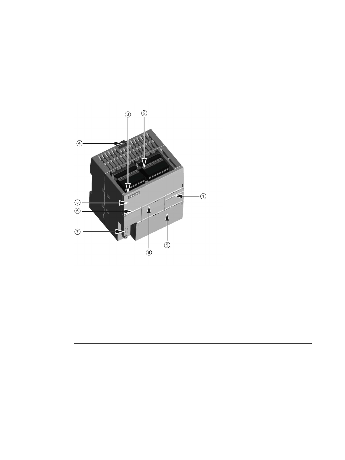
1.1
S7-200 SMART CPU
①
LEDs for the I/O
②
Terminal connectors
③
Ethernet
④
Clip for installation on a
standard (DIN) rail
⑤
Ethernet status LEDs
(under door): LINK, Rx/Tx
⑥
Status LEDs: RUN, STOP and
ERROR
⑦
RS485 Communication port
⑧
Optional signal board
(Standard models only)
⑨
Memory card r
door)
(Standard models only)
Note
CPU CR40 and CPU CR60
S7
CR60 models.
1.1 S7-200 SMART CPU
The CPU combines a microprocessor, an integrated power supply, input circuits, and output
circuits in a compact housing to create a powerful Micro PLC. After you have downloaded
your program, the CPU contains the logic required to monitor and control the input and
output devices in your application.
The CPU provides different models with a diversity of features and capabilities that help you
create effective solutions for your varied applications. The different models of CPUs are
shown below. For detailed information about a specific CPU, see the technical specifications
(Page 685).
communication port
eader (under
S7-200 SMART
18 System Manual, V2.3, 07/2017, A5E03822230-AF
-200 SMART CPU firmware release V2.3 does not apply to the CPU CR40 and CPU

Product overview
SR20
ST20
CR20s
SR30
ST30
CR30s
SR40
ST40
CR40s
SR60
ST60
CR60s
expandable
Relay output
X X X X X X X
X
I/O points (built-in)
20
20
20
30
30
30
40
40
40
60
60
60
Features
CPU CR20s
CPU CR30s
CPU CR40s
CPU CR60s
Dimensions: W x H x D (mm)
90 x 100 x 81
110 x 100 x 81
125 x 100 x 81
175 x 100 x 81
Program
12 Kbytes
12 Kbytes
12 Kbytes
12 Kbytes
User data
8 Kbytes
8 Kbytes
8 Kbytes
8 Kbytes
Retentive
2 Kbytes max.1
2 Kbytes max.1
2 Kbytes max.1
2 Kbytes max.1
Expansion modules
None
None
None
None
Signal board
None
None
None
None
phase
A/B phase
2 at 50 kHz
2 at 50 kHz
2 at 50 kHz
2 at 50 kHz
PID loops
8 8 8
8
back-up
1
ues on retentive timers) to be retentive, up to the specified maximum amount.
1.1 S7-200 SMART CPU
Table 1- 1 S7-200 SMART CPUs
Compact serial, non-
X X X X
Standard, expandable X X X X X X X X
Transistor output (DC) X X X X
Table 1- 2 Compact serial, non-expandable CPUs
User memory
On-board digital I/O
High-speed
• Inputs
• Outputs
Single
• 12 DI
• 8 DQ Relay
• 18 DI
• 12 DQ Relay
• 24 DI
• 16 DQ Relay
4 at 100 kHz 4 at 100 kHz 4 at 100 kHz 4 at 100 kHz
36 DI
24 DQ Relay
counters (4
total)
Real-time clock with 7-day
No No No No
You can configure areas of V memory, M memory, C memory (current values), and portions of T memory (current val-
S7-200 SMART
System Manual, V2.3, 07/2017, A5E03822230-AF
19

Product overview
Features
CPU SR20,
CPU ST20
CPU SR30,
CPU ST30
CPU SR40,
CPU ST40
CPU SR60,
CPU ST60
Dimensions: W x H x D (mm)
90 x 100 x 81
110 x 100 x 81
125 x 100 x 81
175 x 100 x 81
User data
8 Kbytes
12 Kbytes
16 Kbytes
20 Kbytes
Retentive
10 Kbytes max.1
10 Kbytes max.1
10 Kbytes max.1
10 Kbytes max.1
Signal board
1 1 1
1
2 at 30 kHz
1 at 30 kHz
2 at 30 kHz
2 at 30 kHz
2 at 20 kHz
1 at 20 kHz
2 at 20 kHz
2 at 20 kHz
Pulse outputs 2
2 at 100 kHz
3 at 100 kHz
3 at 100 kHz
3 at 100 kHz
PID loops
8 8 8
8
Real-time clock with 7-day back-up
Yes
Yes
Yes
Yes
1
2
The specified maximum pulse frequency is possible only for CPU models with transistor outputs. Pulse output operation
is not recommended for CPU models with relay outputs.
1.1 S7-200 SMART CPU
Table 1- 3 Standard expandable CPUs
User memory Program 12 Kbytes 18 Kbytes 24 Kbytes 30 Kbytes
On-board digital
I/O
• Inputs
• Outputs
• 12 DI
• 8 DQ
• 18 DI
• 12 DQ
• 24 DI
• 16 DQ
• 36 DI
• 24 DQ
Expansion modules 6 max. 6 max. 6 max. 6 max.
High-speed
Single phase 4 at 200 kHz
5 at 200 kHz
4 at 200 kHz
4 at 200 kHz
counters (6
total)
A/B phase 2 at 100 kHz
3 at 100 kHz
2 at 100 kHz
2 at 100 kHz
You can configure areas of V memory, M memory, C memory (current values), and portions of T memory (current val-
ues on retentive timers) to be retentive, up to the specified maximum amount.
Refer to the technical specifications (Page 679) for the power requirements of the CPU and
the expansion modules. Use the worksheets in Appendix B, Calculating a power budget
(Page 790) to calculate your power budget.
S7-200 SMART
20 System Manual, V2.3, 07/2017, A5E03822230-AF

Product overview
1.2
New features
New CPU models
Note
CPU CR40 and CPU CR60
S7
CR60 models.
Status LED states
High Speed Counters (HSC)
USB/PPI serial interface support by STEP 7-Micro/WIN SMART
1.2 New features
STEP 7-Micro/WIN SMART V2.3 and the S7-200 SMART V2.3 CPUs introduce the following
new features:
S7-200 SMART has four new compact serial CPU models:
● CPU CR20s AC/DC/Relay (6ES7288-1CR20-0AA1)
● CPU CR30s AC/DC/Relay (6ES7288-1CR30-0AA1)
● CPU CR40s AC/DC/Relay (6ES7288-1CR40-0AA1)
● CPU CR60s AC/DC/Relay (6ES7288-1CR60-0AA1)
-200 SMART CPU firmware release V2.3 does not apply to the CPU CR40 and CPU
All CPU models now blink the STOP LED at 1 Hz if a value is forced (in RUN or STOP
mode).
New HSC capabilities are as follows:
● The number of HSCs increased from four to six on the SR and ST CPU models. The new
CRs CPUs have four HSCs.
● The SR/ST30 CPUs now utilize the high speed inputs I0.6 and I0.7 for HSC4. This means
that the SR/ST30 CPU has one more 200 kHz counter than the other SR/ST models.
You can now use a USB/PPI Multi-Master cable to program all CPU models through any of
the following serial ports:
● RS485 port
● Signal board port
● DP01 PROFIBUS port
S7-200 SMART
System Manual, V2.3, 07/2017, A5E03822230-AF
21

Product overview
Firmware update with STEP 7-Micro/WIN SMART
See also
1.2 New features
You can now download firmware updates on all CPU models through any of the following
serial ports:
● RS485 port
● Signal board port
● DP01 PROFIBUS port
Creating a user-defined library of instructions (Page 563)
EM DE08 and EM DE16 digital input specifications (Page 725)
EM DT08, EM DR08, EM QR16, and EM QT16 digital output specifications (Page 727)
S7-200 SMART I/O expansion cable (Page 779)
Using STEP 7-Micro/WIN SMART to create your programs (Page 111)
Modbus RTU library (Page 476)
Open user communication library (Page 498)
Open user communication (Page 217)
S7-200 SMART
22 System Manual, V2.3, 07/2017, A5E03822230-AF

Product overview
1.3
CPU feature differences
CRs models
No Ethernet port
1.3 CPU feature differences
The S7-200 SMART V2.3 CPU family includes twelve CPU models, separated into two lines:
the Compact Line and the Standard Line. The first letter of the CPU designator indicates a
line, either Compact (C) or Standard (S). The second letter of the designator indicates AC
power supply / relay outputs (R) or DC power supply / DC transistor (T). The number in the
designator indicates the total onboard digital I/O count. The new compact models are
designated by a lower case "s" character (serial port only) following the I/O count.
The CPU CR20s, CPU CR30s, CPU CR40s, and CPU CR60s models have the following
differences from the standard CPUs:
● No Ethernet port: The RS485 port is now the programming port.
● STEP 7-Micro/WIN SMART uses a USB-PPI cable to program the CPU through the
RS485 port.
● The CPUs reserve one connection for the STEP 7-Micro/WIN SMART programmer
connection.
● No CPU instructions that require an Ethernet port
● No support for data logs
● No real-time clock
● No microSD card reader
● No signal board support
● No signal module support
● No 24 V DC sensor supply
● No motion control
● Support for only PROFIBUS/RS485-capable HMIs
● 12 KB of ladder memory and 8 KB of V memory
● Retentive memory limited to 2 KB
Because the CRs models have no Ethernet port, the RS485 port is the programming port.
STEP 7-Micro/WIN SMART uses the USB-PPI cable to program the CPU. You can now
program any CPU over all serial ports, including the PROFIBUS DP01 modules.
S7-200 SMART
System Manual, V2.3, 07/2017, A5E03822230-AF
23

Product overview
USB-PPI cable
Communication connections
No CPU instructions that require an Ethernet port
LAD instruction
STL instruction
Description
GET
GET
Get data through the Ethernet
GIP_ADDR
GIP
Get Ethernet IP address
SIP_ADDR
SIP
Set Ethernet IP address
TCON
TCON
Open an OUC Ethernet connection
TSEND
TSEND
Send OUC data through the Ethernet
net
tion
No real-time clock
No microSD card reader or any functions related to the use of a microSD card
1.3 CPU feature differences
The CRs models provide the RS485 port as the only programming port for the CPU. Using
STEP 7-Micro/WIN SMART and a USB-PPI cable, you can perform the following tasks:
● Upload and download your program
● Monitor program functions
● Perform firmware updates
If you use Freeport (Page 465) in your program, attaching a USB-PPI cable forces the CPU
to exit Freeport mode and enables PPI mode. PPI mode allows STEP 7-Micro/WIN SMART
to regain control of the CPU.
Since the CRs CPU models support only an RS485 programming port, the CPU always
reserves one connection for the STEP 7-Micro/WIN SMART programmer connection. The
CRs model CPUs still support four connections on the RS485 port for HMIs.
You cannot use the CPU instructions that utilize the Ethernet port on the CRs models. The
instructions that are not available in the CRs models are as follows:
SET SET Write data through the Ethernet
TRECV TRECV Receive OUC data through the Ether-
TDCON TDCON Disconnect an OUC Ethernet connec-
The CRs models do not have a real-time clock; however, the CRs models still support time
instructions. The time resets to the default time (January 1, 2000) on every power cycle. The
CPU maintains time with limited accuracy without the real-time clock.
Because the CRs models do not support a microSD card, you use the Reset to factory
defaults command (Page 164) using the RS485 port in case you forget your password.
S7-200 SMART
24 System Manual, V2.3, 07/2017, A5E03822230-AF

Product overview
HMIs limited to those accessible from PROFIBUS/RS485 networks
1.3 CPU feature differences
The new CRs models only support the following PROFIBUS/RS485-capable HMIs:
● COMFORT HMIs:
– SIMATIC HMI TP700 COMFORT
– SIMATIC HMI TP900 COMFORT
– SIMATIC HMI TP1200 COMFORT
– SIMATIC HMI KP400 COMFORT
– SIMATIC HMI KP700 COMFORT
– SIMATIC HMI KP900 COMFORT
– SIMATIC HMI KP1200 COMFORT
– SIMATIC HMI KTP400 COMFORT
● SMART HMIs:
– SMART 700 IE
– SMART 1000 IE
● BASIC HMIs:
– SIMATIC HMI KTP600 BASIC COLOR DP
– SIMATIC HMI KTP1000 BASIC COLOR DP
● Micro HMIs:
– TD 400C TEXT DISPLAY, 4 LINES
S7-200 SMART
System Manual, V2.3, 07/2017, A5E03822230-AF
25

Product overview
1.4
S7-200 SMART expansion modules
Type
Input only
Output only
Combination In/Out
Other
Module
Type
Description
1.4 S7-200 SMART expansion modules
To better solve your application requirements, the S7-200 SMART family includes a wide
variety of expansion modules, signal boards, and a communications module. You can use
these expansion modules with the standard CPU models (SR20, ST20, SR30, ST30, SR40,
ST40, SR60 or ST60) to add additional functionality to the CPU. The following table provides
a list of the expansion modules that are currently available. For detailed information about a
specific module, see the technical specifications (Page 679).
Table 1- 4 Expansion modules and signal boards
Digital expansion module
Analog expansion modules
Signal boards
• 8 x DC In
• 16 x DC In
• 4 x Analog In
• 8 x Analog In
• 2 x RTD In
• 4 x RTD In
• 4 x TC In
• 1 x Analog In • 1 x Analog Out • 2 x DC In x 2 x DC Out • RS485/RS232
• 8 x DC Out
• 8 x Relay Out
• 16 x Relay Out
• 16 x DC Out
• 2 x Analog Out
• 4 x Analog Out
Table 1- 5 Communication expansion modules
Communication expansion module
(EM)
PROFIBUS DP SMART module EM DP01 PROFIBUS DP
• 8 x DC In / 8 x DC Out
• 8 x DC In / 8 x Relay Out
• 16 x DC In / 16 x DC Out
• 16 x DC In / 16 x Relay Out
• 4 x Analog In / 2 x Analog Out
• 2 x Analog In / 1 x Analog Out
• Battery Board
S7-200 SMART
26 System Manual, V2.3, 07/2017, A5E03822230-AF
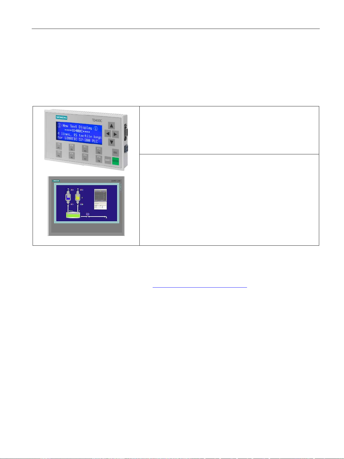
Product overview
1.5
HMI devices for S7-200 SMART
Text Display unit:
to your application.
SMART HMIs:
1.5 HMI devices for S7-200 SMART
The S7-200 SMART supports Comfort HMIs, SMART HMIs, Basic HMIs and Micro HMIs.
The TD400C and the SMART LINE Touch Panel are shown below. Refer to "HMIs and
communication drivers" (Page 398) for a list of supported devices.
Table 1- 6 HMI devices
The TD400C is an RS485-only display device that can be
connected to the CPU. Using the Text Display wizard, you can easily program your CPU to display text messages and other data pertaining to your
application.
The TD400C device provides a low-cost interface to your application by
allowing you to view, monitor, and change the process variables pertaining
The SMART LINE Touch Panel provides operating and
monitoring functions for small-scale machines and plants. Short configuration and commissioning times, their configuration in WinCC flexible (ASIA
version), and a double-port Ethernet/RS485 interface form the highlights of
these HMIs.
The Text Display wizard in STEP 7-Micro/WIN SMART helps you configure Text Display
messages quickly and easily for the TD400C. To start the Text Display wizard, select the
"Text Display" command from the "Tools" menu.
The SIMATIC Text Display (TD) User Manual can be downloaded from the Siemens
customer support web site (http://www.siemens.com/automation/).
S7-200 SMART
System Manual, V2.3, 07/2017, A5E03822230-AF
27

Product overview
1.6
Communications options
Note
The CPU models CPU CR20s, CPU CR30s, CPU CR40s, and CPU CR60s have no
Ethernet port and do not support any functions related to the use of Ethernet
communica
1.6 Communications options
The S7-200 SMART offers several types of communication between CPUs, programming
devices, and HMIs:
● Ethernet:
– Exchange of data from the programming device to the CPU
– Exchange of data between HMIs and the CPU
– S7 peer-to-peer communication with other S7-200 SMART CPUs
– Open User Communication (OUC) with other Ethernet-capable devices
tions.
● PROFIBUS:
– High speed communications for distributed I/O (up to 12 Mbps)
– One bus master connects to many I/O devices (supports 126 addressable devices).
– Exchange of data between the master and I/O devices
– EM DP01 module is a PROFIBUS I/O device.
● RS485:
– Provides a STEP 7-Micro/WIN SMART connection for programming when using a
USB-PPI cable
– Supports a total of 126 addressable devices (32 devices per network segment)
– Supports PPI (point-to-point interface) protocol
– Exchange of data between HMIs and the CPU
– Exchange of data between devices and the CPU using Freeport (XMT/RCV
instructions)
● RS232:
– Supports a point-to-point connection to one device
– Supports PPI protocol
– Exchange of data between HMIs and the CPU
– Exchange of data between devices and the CPU using Freeport (XMT/RCV
instructions)
S7-200 SMART
28 System Manual, V2.3, 07/2017, A5E03822230-AF
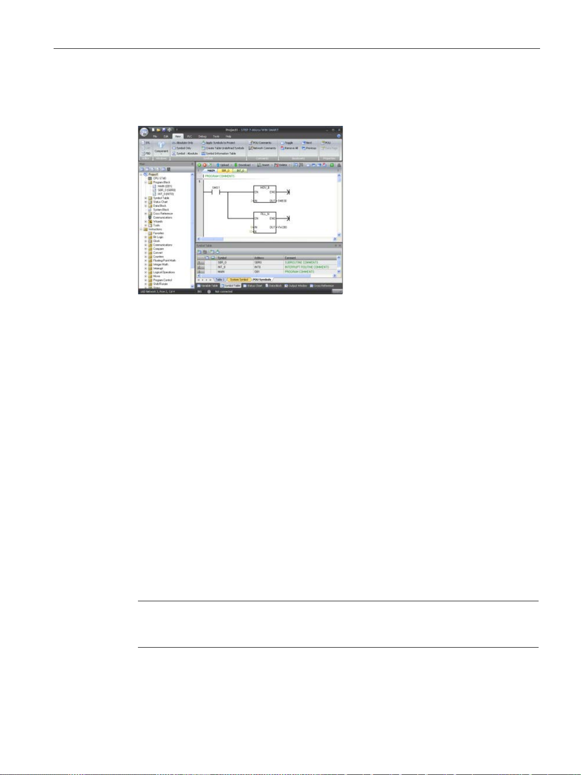
Product overview
1.7
Programming software
STEP7
user
edit, and monitor the logic needed to
control your application.
At the top is a quick access toolbar for
frequent tasks, followed by menus for
all common functions. At the left is the
project tre
easy access to components and i
structions. The program editor and
other components that you open o
cupy the remainder of the user inte
face.
STEP7
three program editors (LAD, FBD, and
STL) for convenience and efficiency in
developing the control program for
your application.
Computer requirements
Installing STEP 7-Micro/WIN SMART
Note
To instal
SMART on a Windows XP or Windows 7 operating system, you
must log in with Administrator privileges.
1.7 Programming software
-Micro/WIN SMART provides a
-friendly environment to develop,
e and navigation bar for
n-
c-
r-
-Micro/WIN SMART provides
To help you find the information you need, STEP7-Micro/WIN SMART provides an extensive
online help system.
STEP 7-Micro/WIN SMART runs on a personal computer. Your computer should meet the
following minimum requirements:
● Operating system: Windows 7 or Windows 10 (both 32 bit and 64 bit versions)
● At least 350M bytes of free hard disk space
● Mouse (recommended)
Insert the STEP 7-Micro/WIN SMART CD into the CD-ROM drive of your computer or
contact your Siemens distributor or sales office to download STEP7-Micro/WIN SMART from
S7-200 SMART
System Manual, V2.3, 07/2017, A5E03822230-AF
the customer support web site (Page 3). Installation starts automatically and prompts you
through the installation process. Refer to the Readme file for more information about
installing STEP 7-Micro/WIN SMART.
l STEP 7-Micro/WIN
29

Product overview
1.7 Programming software
S7-200 SMART
30 System Manual, V2.3, 07/2017, A5E03822230-AF

2
2.1
Connecting to the CPU
Note
The CPU
Ethernet port and no functions related to the use of Ethernet communications.
Connecting power to the CPU
WARNING
Ensure power is off prior to installing, wiring or removing devices
STEP 7-Micro/WIN SMART makes it easy for you to program your CPU. In just a few short
steps using a simple example, you can learn how to create a user program that you can
download and run on your CPU.
All you need for this example is an Ethernet or USB-PPI communication cable, a CPU, and a
programming device running the STEP 7-Micro/WIN SMART programming software.
Connecting your CPU is easy. For this example, you only need to connect power to your
CPU and then connect the Ethernet or USB-PPI communication cable between your
programming device and the CPU.
models CPU CR20s, CPU CR30s, CPU CR40s, and CPU CR60s have no
Before you install or remove any electrical device, ensure that the power to that equipment
has been turned off.
Attempts to install or connect the wiring for the CPU or related equipment with power
applied could cause electric shock or faulty operation of equipment. Failure to disable all
power to the CPU and related equipment during installation or removal procedures could
result in death or serious injury to personnel, and/or damage to equipment.
Always follow appropriate safety precautions and ensure that power to the CPU is disabled
before attempting to install or remove the CPU or related equipment.
S7-200 SMART
System Manual, V2.3, 07/2017, A5E03822230-AF
31

Getting started
DC installation
AC installation
2.1.1
Configuring the CPU for communication
2.1.1.1
Overview
A CPU can communicate with a
STEP
vice on an Ethernet network.
A CPU can co
STEP
vice on an RS485 network.
2.1 Connecting to the CPU
Connect the CPU to a power source. The following figure shows the wiring connections for
either a DC or an AC model of the CPU.
A CPU can communicate with a STEP 7-Micro/WIN SMART programming device on two
types of communications networks:
7-Micro/WIN SMART programming de-
mmunicate with a
7-Micro/WIN SMART programming de-
S7-200 SMART
32 System Manual, V2.3, 07/2017, A5E03822230-AF

Getting started
Note
The CPU models CPU CR20s, CPU CR30s, CPU CR40s, and CPU CR60s have no
Ethernet port and do not support any functions related to the use of Ethernet
communications.
2.1.1.2
Establishing the Ethernet hardware communication connection
①
Ethernet port
2.1 Connecting to the CPU
Consider the following when setting up Ethernet communications between a CPU and a
programming device:
● Configuration/Setup: No hardware configuration is required for a single CPU. If you want
multiple CPU's on the same network, then you must change the default IP addresses to
new, unique IP addresses.
● No Ethernet switch is required for one-to-one communications; an Ethernet switch is
required for more than two devices in a network.
The Ethernet interfaces establish the physical connections between a programming device
and a CPU. Since Auto-Cross-Over functionality is built into the CPU, either a standard or
crossover Ethernet cable can be used for the interface. An Ethernet switch is not required to
connect a programming device directly to a CPU.
Follow the steps below to create the hardware connection between a programming device
and a CPU:
1. Install the CPU.
2. Remove the RJ45 connection cover from the Ethernet port. Retain the cover for reuse.
3. Plug the Ethernet cable into the Ethernet port on the top left of the CPU as shown below.
4. Connect the Ethernet cable to the programming device.
S7-200 SMART
System Manual, V2.3, 07/2017, A5E03822230-AF
33

Getting started
2.1.1.3
Setting up Ethernet communication with the CPU
2.1 Connecting to the CPU
From STEP 7-Micro/WIN SMART, use one of the following methods to display the Ethernet
"Communications" dialog for configuring communication to the CPU.
● From the project tree, double-click the "Communications" node.
● Click the "Communications" button
● Select "Communications" from the "Component" drop-down list in the Windows area of
the "View" menu ribbon strip.
The "Communications" dialog provides two methods of selecting the CPU to be accessed:
● Click the "Find CPUs" button to have STEP 7-Micro/WIN SMART search your local
network for CPUs. The IP address of each CPU found on the network is listed under
"Found CPUs".
● Click the "Add CPU" button to manually enter the access information (IP address and so
forth) for a CPU that you wish to access. The IP address for each CPU, manually added
with this method, is listed under "Added CPUs" and is retained.
from the navigation bar.
S7-200 SMART
34 System Manual, V2.3, 07/2017, A5E03822230-AF

Getting started
Download button from the Transfer area of the File
parameters and repeat these steps.
2.1 Connecting to the CPU
For "Found CPUs" (CPUs located on your local
network), use the "Communications" dialog to
connect with your CPU:
• Select TCP/IP for your Communication Inter-
face.
• Click the "Find CPUs" button to display all
operational CPUs ("Found CPUs") on the local
Ethernet network. All CPUs have a default IP
address. See the Note below.
• Highlight a CPU, and then click "OK".
For "Added CPUs" (CPUs on the local or remote
networks), use the "Communications" dialog to
connect with your CPU:
• Select TCP/IP for your Communication Inter-
face.
• Click the "Add CPU" button to do one of the
following:
– Enter the IP address of a CPU that is ac-
cessible from the programming device, but
is not on the local network.
– Enter the IP address of a CPU directly that
is on the local network.
All CPUs have a default IP address. See the
Note below.
• Highlight a CPU, and then click "OK".
After you have established communication with
the CPU, you are ready to create and download
the example program.
To download all project components, click the
or PLC menu ribbon strip, or alternatively press
the shortcut key combination CTRL+D.
If STEP 7-Micro/WIN SMART does not find your
CPU, check the settings for the communications
S7-200 SMART
System Manual, V2.3, 07/2017, A5E03822230-AF
35

Getting started
Note
The CPU list will show all of the CPUs regardless of Ethernet network class and subnet.
To make a connection to your CPU, your Communication Interface (for Ethernet, a network
interface card (NIC)) and the CPU must be on the same class of network and on the same
subnet. You can either set up your network interface card to match the default IP address of
the CPU, or you can change the IP address of the CPU to match the network c
subnet of your network interface card.
See the "Configuring or changing an IP address for a CPU or device in your project" for
information about how to accomplish this.
2.1.1.4
Establishing the RS485 hardware communication connection
①
RS485 port
2.1 Connecting to the CPU
lass and
The RS485 interfaces establish the physical connections between a programming device
and a CPU.
Follow the steps below to create the hardware connection between a programming device
and a CPU:
1. Install the CPU.
2. Plug the USB/PPI cable into the RS485 port on the bottom left of the CPU as shown
below.
3. Connect the USB/PPI cable to the programming device.
S7-200 SMART
36 System Manual, V2.3, 07/2017, A5E03822230-AF

Getting started
2.1.1.5
Setting up RS485 communication with the CPU
Download button from the Transfer area of the File
parameters and repeat these steps.
2.1 Connecting to the CPU
RS485 network information configuration or changes done in the system block are part of the
project and do not become active until you download your project to the CPU.
To access this dialog, perform one of the following:
● In the "Navigation" bar, click the "System Block" button.
● In the Project tree, select the "System Block" node, then press Enter; or double-click the
"System Block" node.
Enter or change the following access information:
• RS485 port address
• RS485 port baud rate
All CPUs and devices that have valid RS485 port addresses are displayed in the
"Communications" dialog.
In STEP 7-Micro/WIN SMART, you can access CPUs in one of two ways:
● From the project tree, double-click the "Communications" node.
● Click the "Communications" button
● Select "Communications" from the "Component" drop-down list in the Windows area of
the "View" menu ribbon strip.
After you have established communication with
the CPU, you are ready to create and download
the example program.
To download all project components, click the
or PLC menu ribbon strip, or alternatively press
the shortcut key combination CTRL+D.
If STEP 7-Micro/WIN SMART does not find your
CPU, check the settings for the communications
from the navigation bar.
S7-200 SMART
System Manual, V2.3, 07/2017, A5E03822230-AF
37

Getting started
ed.
2.1 Connecting to the CPU
The "Communications" dialog provides two methods of selecting the CPU to be accessed:
● Click the "Find CPUs" button to have STEP 7-Micro/WIN SMART search your local
network for CPUs. The RS485 network address of each CPU found on the network is
listed under "Found CPUs".
● Click the "Add CPU" button to manually enter the access information (RS485 network
address and baud rate) for a CPU that you wish to access. The RS485 network address
for each CPU, manually added with this method, is listed under "Added CPUs" and is
retained.
For "Found CPUs" (CPUs located on the RS485
network), use the "Communications" dialog to
connect with your CPU:
• Select "PC/PPI cable.PPI.1" for your Commu-
nication Interface.
• Click the "Find CPUs" button to display all
operational CPUs ("Found CPUs") on the
RS485 network. All CPUs default their RS485
network settings to address 2 and 9.6 Kbps.
• Highlight a CPU, and then click "OK".
Note: You can open multiple copies of
STEP 7-Micro/WIN SMART on a computer. Be
aware that when you open a second copy of
STEP 7-Micro/WIN SMART or use the "Find
CPUs" button in either copy, the communication
connection to the CPU in your first/other copy of
STEP 7-Micro/WIN SMART might be disconnect-
For "Added CPUs" (CPUs on the RS485 network),
use the "Communications" dialog to connect with
your CPU:
• Select "PC/PPI cable.PPI.1" for your Commu-
nication Interface.
• Click the "Add CPU" button.
• Enter the RS485 network address and baud
rate of a CPU that you wish to access directly
on the RS485 network.
S7-200 SMART
You can add multiple CPUs on the RS485
network. As always, STEP 7-Micro/WIN
SMART communicates with one CPU at a
time. All CPUs default their RS485 network
settings to address 2 and 9.6 Kbps.
• Highlight a CPU, and then click "OK".
38 System Manual, V2.3, 07/2017, A5E03822230-AF

Getting started
2.2
Creating the sample program
LAD/FBD
STL
Description
Network 1
LDN M0.0
TON T33, +100
Network 2
LDW>= T33, +40
= M10.0
Network 3
LD T33
= M0.0
Timing diagram:
2.2 Creating the sample program
Entering this example of a control program will help you understand how easy it is to use
STEP 7-Micro/WIN SMART. This program uses six instructions in three networks to create a
very simple, self-starting timer that resets itself.
For this example, you use the Ladder (LAD) editor to enter the instructions for the program.
The following example shows the complete program in both LAD and Statement List (STL).
The description column explains the logic for each network. The timing diagram shows the
operation of the program. There are no network comments in the STL program.
Table 2- 1 Sample program for getting started with STEP 7-Micro/WIN SMART
10 ms timer T33 times out after (100 x 10 ms = 1 s)
M0.0 pulse is too fast to monitor with Status view.
Comparison becomes true at a rate that is visible
with Status view. Turn on M10.0 after (40 x 10 ms =
0.4 s) for a 40% OFF / 60% ON waveform.
T33 (bit) pulse is too fast to monitor with Status view.
Reset the timer through M0.0 after the (100 x 10 ms
= 1 s) period.
•
•
•
•
•
① T33 (current)
② Current = 100
③ Current = 40
④ T33 (bit) and M0.0
⑤ M10.0
S7-200 SMART
System Manual, V2.3, 07/2017, A5E03822230-AF
39

Getting started
Notice the project tree and the pr
gram editor. You use the project tree
to insert instructions into the networks
of the program editor by dragging and
dropping the instructions from the
"Instructions" portion of the Project
tree to the networks.
The
ject tree contains all of the blocks of
your program.
The program editor toolbar icons pr
vide shortcuts to PLC commands and
programming operation.
2.2.1
Network 1: Starting the timer
Network 1: Starting the timer
When M0.0 is off (0), this contact turns
on and provides power flow to start
the timer.
2.2 Creating the sample program
o-
Program Block folder in the pro-
o-
After you enter and save the program, you can download the program to the CPU.
To enter the contact for M0.0:
1. Either double-click the "Bit Logic" icon or click the plus sign (+) to display the bit logic
instructions.
S7-200 SMART
40 System Manual, V2.3, 07/2017, A5E03822230-AF
2. Select the "Normally Closed" contact.
3. Hold down the left mouse button and drag the contact onto the first network.
4. Enter the following address for the contact: M0.0
5. Press the Return key to enter the address for the contact.

Getting started
2.2.2
Network 2: Turning the output on
Network 2: Turning the output on
When the timer value for T33 is grea
er than or equal to 40 (40 times
10
contact provides power flow to turn on
output M10.0 of the CPU.
2.2 Creating the sample program
To enter the timer instruction for T33:
1. Double-click the "Timers" icon to display the timer instructions.
2. Select the "TON" (on-delay timer) instruction.
3. Hold down the left mouse button and drag the timer onto the first network.
4. Enter the following timer number for the timer: T33
5. Press the Return key to enter the timer number and to move the focus to the preset time
(PT) parameter.
6. Enter the following value for the preset time: +100.
7. Press the Return key to enter the value.
To enter the Compare instruction:
1. Double-click the Compare icon to display the compare instructions. Select the ">=I"
instruction (greater-than-or-equal-to-integer).
2. Hold down the left mouse button and drag the compare instruction onto the second
network.
3. Click "???" above the contact and enter the address for the timer value: T33
4. Press the Return key to enter the timer number and to move the focus to the other value
to be compared with the timer value.
t-
milliseconds, or 0.4 seconds), the
S7-200 SMART
System Manual, V2.3, 07/2017, A5E03822230-AF
5. Enter the following value to be compared with the timer value: +40
6. Press the Return key to enter the value.
41

Getting started
2.2.3
Network 3: Resetting the timer
Network 3: Resetting the timer
When the timer reaches the preset
value (100) and turns the timer bit on,
the contact for T33 turns on. Power
flow from this contact turns on the
M0.0 memory location. Because t
timer is enabled by a Normally Closed
contact for M0.0, changing the state of
M0.0 from off (0) to on (1) resets the
timer.
2.2 Creating the sample program
To enter the instruction for turning on output M10.0:
1. Double-click the Bit Logic icon to display the bit logic instructions and select the output
coil.
2. Hold down the left mouse button and drag the coil onto the second network.
3. Click "???" above the coil and enter the following address: M10.0
4. Press the Return key to enter the address for the coil.
To enter the contact for the timer bit of T33:
1. Select the "Normally Open" contact from the bit logic instructions.
2. Hold down the left mouse button and drag the contact onto the third network.
3. Click "???" above the contact and enter the address of the timer bit: T33
4. Press the Return key to enter the address for the contact.
To enter the coil for turning on M0.0:
1. Select the output coil from the bit logic instructions.
2. Hold down the left mouse button and drag the output coil onto the third network.
3. Click "???" above the coil and enter the following address: M0.0
4. Press the Return key to enter the address for the coil.
S7-200 SMART
42 System Manual, V2.3, 07/2017, A5E03822230-AF
he

Getting started
2.2.4
Setting the CPU type and version for your project
2.2 Creating the sample program
Configure your project for the CPU and version matching your physical CPU. If the project is
not configured for the correct CPU and CPU version, then the download could fail or the
program may not run.
To select your CPU, click the "CPU" field under the "Module" column to display the
dropdown list button, and select your CPU from the dropdown list. Using the same
procedure, select your CPU version in the "Version" column.
S7-200 SMART
System Manual, V2.3, 07/2017, A5E03822230-AF
43

Getting started
2.2.5
Saving the sample project
Saving the sample project
2.2 Creating the sample program
After entering the three networks of instructions, you have finished entering the program.
When you save the program, you create a project that includes the CPU type and other
parameters. To save the project in a file name and location that you specify:
1. Click the down arrow under the Save button from the Operations area of the File menu
ribbon strip to display the Save As button.
2. Click the Save As button and provide a filename for saving your project.
3. Enter a name for the project in the "Save As" dialog.
4. Browse to a location where you want to save your project.
5. Click "Save" to save the project.
After saving the project, you can download the program to the CPU.
S7-200 SMART
44 System Manual, V2.3, 07/2017, A5E03822230-AF

Getting started
2.3
Downloading the sample program
To download all project comp
nents, click the "Download" button
from the "Transfer" area of the
File or PLC menu ribbon strip, or
alternatively press the shortcut
key combination "CTRL+D".
Click the Download dialog "Dow
load" button.
STEP 7
ies the complete program or pr
gram components that you
selected to the CPU.
Note
Each project is associated with a CPU type. If the project type does not match the CPU to
which you are connected, STEP
you to take an a
See also
2.3 Downloading the sample program
First, ensure that your network hardware and PLC connector cable for either Ethernet
(Page 33) (standard CPUs only) or RS485 (Page 36) communications is working, and that
PLC communication is operating properly.
o-
n-
-Micro/WIN SMART copo-
If your CPU is in RUN mode, a dialog prompts you to place the CPU in STOP mode. Clicking
"Yes" sets the CPU to STOP mode.
7-Micro/WIN SMART indicates a mismatch and prompts
ction.
Hardware troubleshooting guide (Page 578)
PLC fatal error codes (Page 796)
Changing the operating mode of the CPU (Page 46)
S7-200 SMART
System Manual, V2.3, 07/2017, A5E03822230-AF
45

Getting started
2.4
Changing the operating mode of the CPU
Placing the CPU in RUN mode
Placing the CPU in STOP mode
2.4 Changing the operating mode of the CPU
The CPU has two modes of operation: STOP mode and RUN mode. The status LEDs on the
front of the CPU indicates the current mode of operation. In STOP mode, the CPU is not
executing the program, and you can download program blocks. In RUN mode, the CPU is
executing the program; however, you can download program blocks.
1. Click the "RUN" button on either the PLC menu ribbon strip or on the program editor
toolbar:
2. When prompted, click "OK" to change the operating mode of the CPU.
You can monitor the program in STEP 7-Micro/WIN SMART by clicking the "Program Status"
button from the "Debug" menu ribbon strip, or from the program editor toolbar.
STEP 7-Micro/WIN SMART displays the values for the instructions.
To stop the program, click the "STOP" button and acknowledge the prompt to place the
CPU in STOP mode. You can also place a STOP instruction in your program logic to put the
CPU in STOP mode.
S7-200 SMART
46 System Manual, V2.3, 07/2017, A5E03822230-AF

3
3.1
Guidelines for installing S7-200 SMART devices
WARNING
Safety requirements for installing S7-200 SMART PLCs
Separate the devices from heat, high voltage, and electrical noise
The S7-200 SMART equipment is designed to be easy to install. You can install the
S7-200 SMART either on a panel or on a standard DIN rail, and you can orient the
S7-200 SMART either horizontally or vertically. The small size of the S7-200 SMART allows
you to make efficient use of space.
S7-200 SMART PLCs are Open Type Controllers. You must install the PLC in a housing,
cabinet, or electric control room. Limit entry to the housing, cabinet, or electric control room
to authorized personnel.
Failure to follow these installation requirements could result in death or serious injury to
personnel, and/or damage to equipment.
Always follow these requirements when installing the PLC.
As a general rule for laying out the devices of your system, always separate the devices that
generate high voltage and high electrical noise from the low-voltage, logic-type devices such
as the PLC.
When configuring the layout of the PLC inside your panel, consider the heat-generating
devices and locate the electronic-type devices in the cooler areas of your cabinet. Reducing
the exposure to a high-temperature environment will extend the operating life of any
electronic device.
Consider also the routing of the wiring for the devices in the panel. Avoid placing low-voltage
signal wires and communications cables in the same tray with AC power wiring and highenergy, rapidly-switched DC wiring.
S7-200 SMART
System Manual, V2.3, 07/2017, A5E03822230-AF
47

Installation
Provide adequate clearance for cooling and wiring
CAUTION
Temperature considerations
①
Side view
③
Vertical installation
②
Horizontal installation
④
Clearance area
3.1 Guidelines for installing S7-200 SMART devices
S7-200 SMART devices are designed for natural convection cooling. For proper cooling, you
must provide a clearance of at least 25 mm above and below the devices. Also, allow at
least 25 mm of depth between the front of the modules and the inside of the enclosure.
Vertical mounting reduces the maximum allowable ambient temperature by 10 degrees C.
Operating outside the maximum temperature range could result in erratic process operation
and could result in minor personal injury.
If your installation includes expansion modules, mount the CPU below them as shown in
the following figure. Follow the prescribed guidelines for mounting modules to ensure
proper cooling.
S7-200 SMART
48 System Manual, V2.3, 07/2017, A5E03822230-AF
When planning your layout for the PLC, allow enough clearance for the wiring and
communications cable connections.

Installation
3.2
Power budget
Note
If the CPU power budget is exceeded, you may not be able to connect the maximum number
of modules allowed for your CPU.
WARNING
Connecting power supplies safely
3.2 Power budget
Your CPU has an internal power supply that provides power for the CPU, the expansion
modules, signal boards, and other 24 V DC user power requirements. Use the following
information as a guide for determining how much power (or current) the CPU can provide for
your configuration. The new compact CPUs (CRs) do not support expansion modules or
signal boards.
Refer to the technical specifications for your particular CPU to determine the 24 V DC sensor
supply power budget, the 5 V DC logic budget supplied by your CPU and the 5 V DC power
requirements of the expansion modules and signal boards. Refer to the Calculating a power
budget (Page 787) to determine how much power (or current) the CPU can provide for your
configuration.
The standard CPU provides the 5 V DC logic power needed for any expansion in your
system. Pay careful attention to your system configuration to ensure that the CPU can
supply the 5 V DC power required by your selected expansion modules. If your configuration
requires more power than the CPU can supply, you must remove a module.
The standard CPU also provides a 24 V DC sensor supply that can supply 24 V DC for input
points, for relay coil power on the expansion modules, or for other requirements. If your
power requirements exceed the budget of the sensor supply, then you must add an external
24 V DC power supply to your system. You must manually connect the 24 V DC supply to
the input points or relay coils.
If you require an external 24 V DC power supply, ensure that the power supply is not
connected in parallel with the sensor supply of the CPU. For improved electrical noise
protection, it is recommended that the commons (M) of the different power supplies be
connected.
Connecting an external 24 V DC power supply in parallel with the 24 V DC sensor supply of
the CPU can result in a conflict between the two supplies as each seeks to establish its
own preferred output voltage level.
The result of this conflict can be shortened lifetime or immediate failure of one or both
power supplies, with consequent unpredictable operation of the PLC system. Unpredictable
operation could result in death or serious injury to personnel, and/or damage to equipment.
The DC sensor supply of the CPU and any external power supply should provide power to
different points. A single connection of the commons is allowed.
S7-200 SMART
System Manual, V2.3, 07/2017, A5E03822230-AF
49

Installation
WARNING
Avoiding unwanted current flow
3.2 Power budget
Some of the 24 V DC power input ports in the S7-200 SMART system are interconnected,
with a common logic circuit connecting multiple M terminals. For example, the following
circuits are interconnected when designated as "not isolated" in the data sheets: the 24 V
DC power supply of the CPU, the power input for the relay coil of an EM, or the power supply
for a non-isolated analog input. All non-isolated M terminals must connect to the same
external reference potential.
Connecting non-isolated M terminals to different reference potentials will cause unintended
current flows that may cause damage or unpredictable operation in the PLC and any
connected equipment.
Failure to comply with these guidelines could cause damage or unpredictable operation
which could result in death or severe personal injury and/or property damage.
Always ensure that all non-isolated M terminals in an S7-200 SMART system are
connected to the same reference potential.
Refer to the technical specifications for your particular CPU to determine the 24 V DC sensor
supply power budget, the 5 V DC logic budget supplied by your CPU and the 5 V DC power
requirements of the expansion modules and signal boards.
S7-200 SMART
50 System Manual, V2.3, 07/2017, A5E03822230-AF

Installation
3.3
Installation and removal procedures
3.3.1
Mounting dimensions for the S7-200 SMART devices
S7-200 SMART module
Width A (mm)
Width B (mm)
CPU SR20, CPU ST20, and CPU CR20s
90
45
CPU SR30, CPU ST30, and CPU CR30s
110
55
CPU SR40, CPU ST40, and CPU CR40s
125
62.5
CPU SR60, CPU ST60, and CPU CR60s1
175
37.51
Transistor
EM 8DI/8DQ and EM 8DI/8DQ RLY
45
22.5
EM 16DI/16DQ and EM 16DI/16DQRLY
70
35
EM 2AI/1AQ and EM 4AI/2AQ
45
22.5
EM 2RTD, EM 4RTD
45
22.5
EM 4TC
45
22.5
EM DP01
70
35
mounting hole to the corresponding edge of the housing.
Note
The compact serial CPUs (CPU SR20s, CPU SR30s, CPU SR40s, and CPU SR60s) do not
support expansion modules or signal boards.
3.3 Installation and removal procedures
The CPU and expansion modules include mounting holes to facilitate installation on panels.
Expansion modules: EM 4AI, EM 8AI, EM 2AQ, EM 4AQ, EM 8DI, EM 16DI, EM
8DQ, and EM 8DQ RLY, EM 16DQ RLY, and EM 16DQ
1
The CPU xx60 models have two sets of mounting holes. The width "B" dimension is measured from the center of each
45 22.5
S7-200 SMART
System Manual, V2.3, 07/2017, A5E03822230-AF
51

Installation
3.3.2
Installing and removing the CPU
①
DIN rail installation
③
Panel installation
②
DIN rail clip in latched position
④
Clip in extended position
WARNING
Remove power to PLC before installing or removing equipment
WARNING
Module replacement
3.3 Installation and removal procedures
The CPU can be easily installed on a standard DIN rail or on a panel. DIN rail clips are
provided to secure the device on the DIN rail. The clips also snap into an extended position
to provide a screw mounting position for panel-mounting the unit.
Figure 3-1 Installation on a DIN rail or on a panel
Before you install or remove any electrical device, ensure that the power to that equipment
has been turned off. Also, ensure that the power to any related equipment has been turned
off.
Attempts to install or remove the PLC or related equipment with the power applied could
cause electric shock or faulty operation of equipment.
Failure to disable all power to the PLC and related equipment during installation or removal
procedures could result in death or serious injury to personnel, and/or damage to
equipment.
Always follow appropriate safety precautions and ensure that power to the PLC is disabled
before attempting to install or remove the CPU or related equipment.
Always ensure that whenever you replace or install a device, you use the correct module or
equivalent device.
If you install an incorrect module, the program in the CPU could function unpredictably.
Failure to replace a device with the same model, orientation, or order could result in death
or serious injury to personnel, and/or damage to equipment.
Replace the device with the same model, and be sure to orient and position it correctly.
S7-200 SMART
52 System Manual, V2.3, 07/2017, A5E03822230-AF

Installation
Note
Install expansion modules separately after the CPU has been installed. The CPU model
CPU CR20s, CPU CR30s, CPU CR40s, and CPU CR60s do not support the use of
expansion modules or signal boards.
Note
The type of screw will be determined by the material upon which it is mounted. You
should apply appropriate torque until the spring washer becomes flat. Av
excessive torque to the mounting screws. Do not use a flat head screw.
3.3 Installation and removal procedures
s
Consider the following when installing the units on the DIN rail or on a panel:
● For DIN rail mounting, make sure the upper DIN rail clip is in the latched (inner) position
and that the lower DIN rail clip is in the extended position for the CPU.
● After installing the devices on the DIN rail, move the lower DIN rail clips to the latched
position to lock the devices on the DIN rail.
● For panel mounting, make sure the DIN rail clips are pushed to the extended position.
To install the CPU on a panel, follow these steps:
1. Locate, drill, and tap the mounting holes (M4 or American Standard number 8), using the
dimensions in the table, Mounting dimensions (mm) (Page 51).
2. Ensure that the CPU and S7-200 SMART equipment are disconnected from electrical
power.
3. Secure the module(s) to the panel, using a Pan Head M4 screw with spring and flat
washer. Do not use a flat head screw.
4. If you are using an expansion module, put it next to the CPU and slide together until the
connectors join securely.
oid applying
S7-200 SMART
System Manual, V2.3, 07/2017, A5E03822230-AF
53

Installation
Task
Procedure
Note
Using DIN rail stops could be helpful if your CPU is in an environment with high vibration
potential or if the CPU has been installed vertically. Use an end bracket (8WA1 808 or 8WA1
805) on the DIN rail to
If your system is in a high
mounting the CPU will provide a
greater level of vibrati
Task
Procedure
3.3 Installation and removal procedures
Table 3- 1 Installing a CPU on a DIN rail
Follow the steps below to install a CPU on a DIN rail.
1. Secure the rail to the mounting panel every 75 mm.
2. Snap open the DIN clip (located on the bottom of the module) and hook the back of
the module onto the DIN rail.
3. Rotate the module down to the DIN rail and snap the clip closed. Carefully check
that the clip has fastened the module securely onto the rail. To avoid damage to the
module, press on the tab of the mounting hole instead of pressing directly on the
front of the module.
on protection.
Table 3- 2 Removing a CPU from a DIN rail
Follow the steps below to remove a CPU from a DIN rail.
1. Remove power from the CPU and any attached I/O modules.
2. Disconnect all the wiring and cabling that is attached to the CPU. The CPU and
most expansion modules have removable connectors to make this job easier.
3. Unscrew the mounting screws or snap open the DIN clip.
4. If you have expansion modules connected, slide the CPU to the left to disengage it
from the expansion module connector. Note: unscrewing or unsnapping the DIN
clips of the expansion modules can make it easier to disengage the CPU.
5. Remove the CPU.
ensure that the modules remain connected.
-vibration environment, then panel-
S7-200 SMART
54 System Manual, V2.3, 07/2017, A5E03822230-AF

Installation
3.3.3
Installing and removing a signal board or battery board
Task
Procedure
Task
Procedure
3.3 Installation and removal procedures
The CPU models CPU CR20s, CPU CR30s, CPU CR40s, and CPU CR60s do not support
the use of expansion modules, signal boards or battery boards.
Table 3- 3 Installing a signal board on a CPU
Follow the steps below to install a signal board or battery board
1. Ensure that the CPU and all S7-200 SMART equipment are disconnected from electrical power.
2. Remove the top and bottom terminal block covers from the CPU.
3. Place a screwdriver into the slot on top of the CPU at the rear of the cover.
4. Gently pry the cover up and remove it from the CPU.
5. Place the signal board or battery board straight down into its mounting position in the
top of the CPU.
6. Firmly press the module into position until it snaps into place.
7. Replace the terminal block covers.
Table 3- 4 Removing a signal board or battery board on a CPU
Follow the steps below to remove a signal board or battery board
1. Ensure that the CPU and all S7-200 SMART equipment are disconnected from electrical power.
2. Remove the top and bottom terminal block covers from the CPU.
3. Place a screwdriver into the slot on top of the module.
4. Gently pry the module up to disengage it from the CPU.
5. Remove the module straight up from its mounting position in the top of the CPU.
6. Replace the cover onto the CPU.
7. Replace the terminal block covers.
S7-200 SMART
System Manual, V2.3, 07/2017, A5E03822230-AF
55

Installation
Note
The CPU models CPU CR20s, CPU CR30s, CPU CR40s, and CPU CR60s do not support
the use of expansion modules or signal boards.
Installing or replacing the battery in the SB BA01 battery board
3.3 Installation and removal procedures
The SB BA01 battery board requires battery type CR1025. The battery is not included with
the SB BA01 and must be purchased.
To install the battery, follow these steps:
1. In the SB BA01, install the new battery with the positive side of the battery on top, and the
negative side next to the printed wiring board.
2. The SB BA01 is now ready to be installed in the CPU. Follow the installation directions
above.
To replace the battery, follow these steps:
1. Remove the SB BA01 from the CPU following the removal directions above.
2. Carefully remove the old battery using a small screwdriver. Push the battery out from
under the clip.
3. Install a new CR1025 replacement battery with the positive side of the battery on top and
the negative side next to the printed wiring board.
4. Re-install the SB BA01 battery board following the installation directions above.
S7-200 SMART
56 System Manual, V2.3, 07/2017, A5E03822230-AF

Installation
3.3.4
Removing and reinstalling the terminal block connector
Task
Procedure
Task
Procedure
3.3 Installation and removal procedures
The S7-200 SMART modules have removable connectors to make connecting the wiring
easy.
Table 3- 5 Removing the connector
Table 3- 6 Installing the connector
Prepare the system for terminal block removal by removing the power from the CPU
and opening the cover above the connector.
1. Ensure that the CPU and all S7-200 SMART equipment are disconnected from
2. Inspect the top of the connector and locate the slot for the tip of the screwdriver.
3. Insert a small screwdriver into the slot.
4. Gently pry the top of the connector away from the CPU. The connector will release
5. Grasp the connector and remove it from the CPU.
electrical power.
with a snap.
S7-200 SMART
System Manual, V2.3, 07/2017, A5E03822230-AF
Prepare the components for terminal block installation by removing power from the
CPU and opening the cover above the connector.
1. Ensure that the CPU and all S7-200 SMART equipment are disconnected from
electrical power.
2. Align the connector with the pins on the unit.
3. Align the wiring edge of the connector inside the rim of the connector base.
4. Press firmly down and rotate the connector until it snaps into place.
Check carefully to ensure that the connector is properly aligned and fully engaged.
57

Installation
3.3.5
Installing and removing an expansion module
Task
Procedure
3.3 Installation and removal procedures
Install expansion modules separately after the CPU has been installed. The CPU models
CPU CR20s, CPU CR30s, CPU CR40s, and CPU CR60s do not support the use of
expansion modules or signal boards.
Table 3- 7 Installing an expansion module
Follow the steps below to install an expansion module:
1. Ensure that the CPU and all S7-200 SMART equipment are disconnected from
electrical power.
2. Remove the cover for the I/O bus connector from the right side of the CPU.
3. Insert a screwdriver into the slot above the cover.
4. Gently pry the cover out at its top and remove the cover. Retain the cover for
reuse.
Connect the expansion module to the CPU.
1. Pull out the bottom DIN rail clip to allow the expansion module to fit over the
rail.
2. Position the expansion module to the right of the CPU.
3. Hook the expansion module over the top of the DIN rail.
4. Slide the expansion module to the left until the I/O connector fully engages the
connector on the right of the CPU and push the bottom clip in to latch the expansion module onto the rail.
S7-200 SMART
58 System Manual, V2.3, 07/2017, A5E03822230-AF

Installation
Task
Procedure
3.3 Installation and removal procedures
Table 3- 8 Removing an expansion module
Follow the steps below to remove an expansion module:
1. Ensure that the CPU and all S7-200 SMART equipment are disconnected from
electrical power.
2. Remove the I/O connectors and wiring from the expansion module. Loosen the
DIN rail clips of all the S7-200 SMART devices.
3. Physically slide the expansion module to the right.
S7-200 SMART
System Manual, V2.3, 07/2017, A5E03822230-AF
59

Installation
3.3.6
Installing and removing the expansion cable
Task
Procedure
3.3 Installation and removal procedures
The S7-200 SMART expansion cable provides additional flexibility in configuring the layout
of your S7-200 SMART system. Only one expansion cable is allowed per CPU system. You
install the expansion cable either between the CPU and the first EM, or between any two
EMs.
Table 3- 9 Installing and removing the male connector of the expansion cable
To install the male connector:
1. Ensure that the CPU and all S7-200 SMART equipment are
disconnected from electrical power.
2. Push the male connector into the bus connector on the right
side of the expansion module or CPU.
3. The male connector is locked in place when it is fully seeded.
To remove the male connector:
1. Ensure that the CPU and all S7-200 SMART equipment are
disconnected from electrical power.
2. Use your thumb to press down the latch on the top of the
male connector to release it from the expansion module or
CPU.
3. Remove the male connector from the expansion module or
CPU by pulling it straight out.
S7-200 SMART
60 System Manual, V2.3, 07/2017, A5E03822230-AF

Installation
Task
Procedure
Remove the female connector from the expansion module by
Note
Installing the expansion cable in a vibration environment
If the expansion cable is connected to modules that move or are not firmly fixed, the
connection on the cable ends can gradually become loose.
Use a cable
relief.
Avoid using excessive force when you pull the cable during installation. Ensure the cable
module connection is in the correct position once installation is complete.
3.3 Installation and removal procedures
Table 3- 10 Installing and removing the female connector of the expansion cable
To install the female connector:
1. Ensure that the CPU and all S7-200 SMART equipment are
disconnected from electrical power.
2. Push the female connector into the bus connector on the left
side of the expansion module.
3. The female connector is locked in place when it is fully seeded.
To remove the female connector:
1. Ensure that the CPU and all S7-200 SMART equipment are
disconnected from electrical power.
2. Use your thumb to press down the latch on the top of the
female connector to release it from the expansion module.
3.
pulling it straight out.
tie to fix the cable ends on the DIN-rail (or other place) to provide extra strain
-
S7-200 SMART
System Manual, V2.3, 07/2017, A5E03822230-AF
61

Installation
3.4
Wiring guidelines
Prerequisites
WARNING
WARNING
3.4 Wiring guidelines
Proper grounding and wiring of all electrical equipment is important to help ensure the
optimum operation of your system and to provide additional electrical noise protection for
your application and the PLC. Refer to the technical specifications (Page 679) for the wiring
diagrams.
Before you ground or install wiring to any electrical device, ensure that the power to that
equipment has been turned off. Also, ensure that the power to any related equipment has
been turned off.
Ensure that you follow all applicable electrical codes when wiring the PLC and related
equipment. Install and operate all equipment according to all applicable national and local
standards. Contact your local authorities to determine which codes and standards apply to
your specific case.
Attempts to install or wire the PLC or related equipment with power applied could cause
electric shock or faulty operation of equipment. Failure to disable all power to the PLC and
related equipment during installation or removal procedures could result in death or serious
injury to personnel, and/or damage to equipment.
Always follow appropriate safety precautions and ensure that power to the PLC is disabled
before attempting to install or remove the PLC or related equipment.
Always take safety into consideration as you design the grounding and wiring of your PLC
system. Electronic control devices, such as the PLC, can fail and can cause unexpected
operation of the equipment that is being controlled or monitored. For this reason, you should
implement safeguards that are independent of the PLC to protect against possible personal
injury or equipment damage.
Control devices can fail in an unsafe condition, resulting in unexpected operation of
controlled equipment. Such unexpected operations could result in death or serious injury to
personnel, and/or damage to equipment.
Use an emergency stop function, electromechanical overrides, or other redundant
safeguards that are independent of the PLC.
S7-200 SMART
62 System Manual, V2.3, 07/2017, A5E03822230-AF

Installation
Isolation guidelines
WARNING
Safe use of power converters
Grounding guidelines
3.4 Wiring guidelines
The AC power supply boundaries and I/O boundaries to AC circuits have been designed and
approved to provide safe separation between AC line voltages and low voltage circuits.
These boundaries include double or reinforced insulation, or basic plus supplementary
insulation, according to various standards. Components which cross these boundaries such
as optical couplers, capacitors, transformers, and relays have been approved as providing
safe separation. Only circuits rated for AC line voltage include safety isolation to other
circuits. Isolation boundaries between 24 V DC circuits are functional only, and you should
not depend on these boundaries for safety.
The sensor supply output, communications circuits, and internal logic circuits of an S7-200
SMART with included AC power supply are sourced as SELV (safety extra-low voltage)
according to EN 61131-2.
To maintain the safe character of the S7-200 SMART low voltage circuits, external
connections to communications ports, analog circuits, and all 24 V DC nominal power supply
and I/O circuits must be powered from approved sources that meet the requirements of
SELV, PELV, Class 2, Limited Voltage, or Limited Power according to various standards.
Use of non-isolated or single insulation supplies to supply low voltage circuits from an AC
line can result in hazardous voltages appearing on circuits that are expected to be touch
safe, such as communications circuits and low voltage sensor wiring.
Such unexpected high voltages could result in death or serious injury to personnel, and/or
damage to equipment.
Use only high-voltage-to-low-voltage power converters that are approved as sources of
touch-safe, limited-voltage circuits.
The best way to ground your application is to ensure that all the common and ground
connections of your PLC and related equipment are grounded to a single point. This single
point should be connected directly to the earth ground for your system.
All ground wires should be as short as possible and should use a large wire size, such as
2 mm
When locating grounds, remember to consider safety grounding requirements and the proper
operation of protective interrupting devices.
2
(14 AWG).
S7-200 SMART
System Manual, V2.3, 07/2017, A5E03822230-AF
63

Installation
Wiring guidelines
3.4 Wiring guidelines
When designing the wiring for your S7-200 SMART CPU, provide a single disconnect switch
that simultaneously removes power from the CPU power supply, from all input circuits, and
from all output circuits. Provide over-current protection, such as a fuse or circuit breaker, to
limit fault currents on supply wiring. Consider providing additional protection by placing a
fuse or other current limit in each output circuit.
Install appropriate surge suppression devices for any wiring that could be subject to lightning
surges.
Avoid placing low-voltage signal wires and communications cables in the same wire tray with
AC wires and high-energy, rapidly switched DC wires. Always route wires in pairs, with the
neutral or common wire paired with the hot or signal-carrying wire.
Use the shortest wire possible and ensure that the wire is sized properly to carry the required
current.
Use wire and cable with a temperature rating 30 °C higher than the ambient temperature
around the S7-200 SMART CPU (for example, a minimum of 85 °C-rated conductors for 55
°C ambient temperature). You should determine other wiring type and material requirements
from the specific electrical circuit ratings and your installation environment.
Use shielded wires for optimum protection against electrical noise. Typically, grounding the
shield at the S7-200 SMART CPU gives the best results. You should ground communication
cable shields to S7-200 SMART CPU communication connector shells using connectors that
engage the cable shield, or by bonding the communication cable shields to a separate
ground. You should ground other cable shields using clamps or copper tape around the
shield to provide a high surface area connection to the grounding point.
When wiring input circuits that are powered by an external power supply, include an
overcurrent protection device in that circuit. External protection is not necessary for circuits
that are powered by the 24 V DC sensor supply from the S7-200 SMART CPU because the
sensor supply is already current-limited.
All S7-200 SMART CPU modules have removable connectors for user wiring. To prevent
loose connections, ensure that the connector is seated securely and that the wire is installed
securely into the connector.
To help prevent unwanted current flows in your installation, the S7-200 SMART CPU
provides isolation boundaries at certain points. When you plan the wiring for your system,
you should consider these isolation boundaries. Refer to the technical specifications
(Page 679) for the amount of isolation provided and the location of the isolation boundaries.
Circuits rated for AC line voltage include safety isolation to other circuits. Isolation
boundaries between 24 V DC circuits are functional only, and you should not depend on
these boundaries for safety.
S7-200 SMART
64 System Manual, V2.3, 07/2017, A5E03822230-AF

Installation
Wiring rules for...
CPU and EM connector
SB connector
sections for standard wires
Wire strip length
6.4 mm
6.3 to 7 mm
Tightening torque* (maximum)
0.56 N-m (5 inch-pounds)
0.33 N-m (3 inch-pounds)
Tool
2.5 to 3.0 mm flathead screwdriver
2.0 to 2.5 mm flathead screwdriver
* To avoid damaging the connector, be careful that you do not over-tighten the screws.
Note
Ferr
short circuits. Ferrules longer than the recommended strip length should include an
insulating collar to prevent shorts due to side movement of conductors. Cross
limits for bare conductors also apply to ferrules.
See also
Guidelines for lamp loads
Guidelines for inductive loads
3.4 Wiring guidelines
A summary of wiring rules for the S7-200 SMART CPUs, EMs, and SBs is shown below:
Table 3- 11 Wiring rules for S7-200 SMART CPUs, EMs, and SBs
Connectible conductor cross-
Number of wires per connection 1 or combination of 2 wires up to 2 mm2
2 mm2 to 0.3 mm2 (14 AWG to 22 AWG) 1.3 mm2 to 0.3 mm2 (16 AWG to 22 AWG)
(total)
ules or end sleeves on stranded conductors reduce the risk of stray strands causing
General technical specifications (Page 679)
1 or combination of 2 wires up to 1.3 mm2
(total)
-sectional area
Lamp loads are damaging to relay contacts because of the high turn-on surge current. This
surge current will nominally be 10 to 15 times the steady state current for a tungsten lamp. A
replaceable interposing relay or surge limiter is recommended for lamp loads that will be
switched a large number of times during the lifetime of the application.
Use suppressor circuits with inductive loads to limit the voltage rise when a control output
turns off. Suppressor circuits protect your outputs from premature failure caused by the high
voltage transient that occurs when current flow through an inductive load is interrupted.
In addition, suppressor circuits limit the electrical noise generated when switching inductive
loads. High frequency noise from poorly suppressed inductive loads can disrupt the
operation of the PLC. Placing an external suppressor circuit so that it is electrically across
the load and physically located near the load is the most effective way to reduce electrical
noise.
S7-200 SMART DC outputs include internal suppressor circuits that are adequate for
inductive loads in most applications. Since S7-200 SMART relay output contacts can be
used to switch either a DC or an AC load, internal protection is not provided.
S7-200 SMART
System Manual, V2.3, 07/2017, A5E03822230-AF
65

Installation
Note
The effectiveness of a suppressor circuit depends on the application and must be verified for
your particular usage. Ensure that all components are correctly rated and use an
oscilloscope to observe the
Typical suppressor circuit for DC or relay outputs that switch DC inductive loads
In most appli
across a DC inductive load is suitable, but if your
application requires faster turn
addition of a zener diode (B) is recommended. Be
sure to size your zener diode properly for the amount
of current
①
1N4001 diode or equivalent
②
8.2 V Zener (DC outputs),
36 V Zener (Relay outputs)
③
Output point
④
M, 24 V reference
3.4 Wiring guidelines
A good suppressor solution is to use contactors and other inductive loads for which the
manufacturer provides suppressor circuits integrated in the load device, or as an optional
accessory. However, some manufacturer provided suppressor circuits may be inadequate
for your application. An additional suppressor circuit may be necessary for optimal noise
reduction and contact life.
For AC loads, a metal oxide varistor (MOV) or other voltage clamping device may be used
with a parallel RC circuit, but is not as effective when used alone. An MOV suppressor with
no parallel RC circuit often results in significant high frequency noise up to the clamp
voltage.
A well-controlled turn-off transient will have a ring frequency of no more than 10 kHz, with
less than 1 kHz preferred. Peak voltage for AC lines should be within +/- 1200 V of ground.
Negative peak voltage for DC loads using the PLC internal suppression will be ~40 V below
the 24 V DC supply voltage. External suppression should limit the transient to within 36 V of
the supply to unload the internal suppression.
turn-off transient.
cations, the addition of a diode (A)
-off times, then the
in your output circuit.
S7-200 SMART
66 System Manual, V2.3, 07/2017, A5E03822230-AF

Installation
Typical suppressor circuit for relay outputs that switch AC inductive loads
Ensure that the working voltage of the metal oxide
varistor (MOV) is at least 20% greater than the nom
nal line voltage.
Choose pulse
ca
cally metal film). Verify the components meet ave
age power, peak power, and peak voltage
requirements.
①
See table for C value
②
See table for R value
③
Output point
Inductive load
Suppressor values
I rms
230 V AC
120 V AC
Resistor
Capacitor
Amps
VA
VA
Ω
W (power rating)
nF
0.02
4.6
2.4
15000
0.1
15
0.05
11.5
6
5600
0.25
470
0.1
23
12
2700
0.5
100
0.2
46
24
1500
1
150
0.5
115
60
560
2.5
470
1
230
120
270
5
1000 2 460
240
150
10
1500
Conditions satisfied by the table values:
Power factor of 0.3 assumed for typical inductive load
3.4 Wiring guidelines
i-
-rated, non-inductive resistors, and
pacitors recommended for pulse applications (typi-
r-
If you design your own suppressor circuit, the following table suggests resistor and capacitor
values for a range of AC loads. These values are based on calculations with ideal
component parameters. I rms in the table refers to the steady-state current of the load when
fully ON.
Table 3- 12 AC suppressor circuit resistor and capacitor values
Maximum turn-off transition step < 500 V
Resistor peak voltage < 500 V
Capacitor peak voltage < 1250 V
Suppressor current < 8% of load current (50 Hz)
Suppressor current < 11% of load current (60 Hz)
Capacitor dV/dt < 2 V/μs
Capacitor pulse dissipation : ∫(dv/dt)
Resonant frequency < 300 Hz
Resistor power for 2 Hz max switching frequency
2
dt < 10000 V2/μs
S7-200 SMART
System Manual, V2.3, 07/2017, A5E03822230-AF
67

Installation
WARNING
Correct placement of external resistor/capacitor noise suppression circuit
3.4 Wiring guidelines
When you use relay expansion modules to switch AC inductive loads, you must place the
external resistor/capacitor noise suppression circuit across the AC load to prevent
unexpected machine or process operation. Unexpected machine or process operation
could result in death or severe personal injury.
Always be sure to follow these guidelines in placing the external resistor/capacitor noise
suppression circuit.
S7-200 SMART
68 System Manual, V2.3, 07/2017, A5E03822230-AF

4
4.1
Execution of the control logic
The figure shows a simple diagram of
how an electrical relay diagram relates
to the CPU. In this example, the state
of the switch for starting the motor is
combined with the states of other i
puts. T
then determine the state for the output
that goes to the actuator which starts
the motor.
The basic function of the CPU is to monitor field inputs and, based on your control logic, turn
on or off field output devices. This chapter explains the concepts used to execute your
program, the various types of memory used, and how that memory is retained.
The CPU continuously cycles through the control logic in your program, reading and writing
data. The basic operation is very simple:
● The CPU reads the status of the inputs.
● The program that is stored in the CPU uses these inputs to evaluate the control logic.
● As the program runs, the CPU updates the data.
● The CPU writes the data to the outputs.
n-
he calculations of these states
S7-200 SMART
System Manual, V2.3, 07/2017, A5E03822230-AF
69

PLC concepts
Tasks in a scan cycle
Scan cycle
Description
cal inputs to the process image input register.
in the various memory areas.
forms any tasks required for communications.
modules are working properly.
4.1 Execution of the control logic
The CPU executes a series of tasks repetitively. This cyclical execution of tasks is called the
scan cycle. The execution of the user program is dependent upon whether the CPU is in
STOP mode or in RUN mode. In RUN mode, your program is executed; in STOP mode, your
program is not executed.
Table 4- 1 Tasks performed by the CPU in a scan cycle
Reading the inputs: The CPU copies the state of the physi-
Executing the control logic in the program: The CPU executes the instructions of the program and stores the values
Processing any communications requests: The CPU per-
Executing the CPU self-test diagnostics: The CPU ensures
that the firmware, the program memory, and any expansion
Writing to the outputs: The values stored in the process
image output register are written to the physical outputs.
S7-200 SMART
70 System Manual, V2.3, 07/2017, A5E03822230-AF

PLC concepts
4.1.1
Reading the inputs and writing to the outputs
Reading the inputs
Writing to the outputs
4.1.2
Immediately reading or writing the I/O
Note
When you read an analog input, the value is read immediately. When you write a value to an
analog output, the ou
4.1 Execution of the control logic
Digital inputs: Each scan cycle begins by reading the current value of the digital inputs and
then writing these values to the process image input register.
Analog inputs:
cycle. Instead, an analog value is read immediately from the device when your program
accesses the analog input.
Digital outputs: At the end of every scan cycle, the CPU writes the values stored in the
process-image output register to the digital outputs.
Analog outputs:
cycle. Instead, the analog outputs are written immediately when your program accesses the
analog output.
The CPU instruction set provides instructions that immediately read from or write to the
physical I/O. These immediate I/O instructions allow direct access to the actual input or
output point, even though the image registers are normally used as either the source or the
destination for I/O accesses. The corresponding process image input register location is not
modified when you use an immediate instruction to access an input point. The corresponding
process image output register location is updated simultaneously when you use an
immediate instruction to access an output point.
The CPU does not read the analog input values as part of the normal scan
The CPU does not write analog output values as part of the normal scan
tput is updated immediately.
It is usually advantageous to use the process image register rather than to directly access
inputs or outputs during the execution of your program. There are three reasons for using the
image registers:
● The sampling of all inputs at the start of the scan synchronizes and freezes the values of
the inputs for the program execution phase of the scan cycle. The outputs are updated
from the image register after the execution of the program is complete. This provides a
stabilizing effect on the system.
● Your program can access the image register much more quickly than it can access I/O
points, allowing faster execution of the program.
● I/O points are bit entities and must be accessed as bits or bytes, but you can access the
image register as bits, bytes, words, or double words. Thus, the image registers provide
additional flexibility.
S7-200 SMART
System Manual, V2.3, 07/2017, A5E03822230-AF
71

PLC concepts
4.1.3
Executing the user program
4.1 Execution of the control logic
During the execution phase of the scan cycle, the CPU executes your main program, starting
with the first instruction and proceeding to the last instruction. The immediate I/O instructions
give you immediate access to inputs and outputs during the execution of either the main
program or an interrupt routine.
If you use subroutines in your program, the subroutines are stored as part of the program.
The subroutines are executed when they are called by the main program, by another
subroutine, or by an interrupt routine. Subroutine nesting depth is 8 levels deep from the
main and 4 levels deep from an interrupt routine.
If you use interrupts in your program, the interrupt routines that are associated with the
interrupt events are stored as part of the program. The interrupt routines are not executed as
part of the normal scan cycle, but are executed when the interrupt event occurs (which could
be at any point in the scan cycle).
Local memory is reserved for each of 14 entities: the main program, eight subroutine nesting
levels when initiated from the main program, one interrupt routine, and four subroutine
nesting levels when initiated from an interrupt routine. Local memory has a local scope in
that it is available only within its associated program entity, and cannot be accessed by the
other program entities. For more information about Local memory, refer to Local Memory
Area: L in this chapter.
S7-200 SMART
72 System Manual, V2.3, 07/2017, A5E03822230-AF

PLC concepts
4.1 Execution of the control logic
The following figure depicts the flow of a typical scan including the Local memory usage and
two interrupt events, one during the program-execution phase and another during the
communications phase of the scan cycle. Subroutines are called by the next higher level,
and are executed when called. Interrupt routines are not called; they are a result of an
occurrence of the associated interrupt event.
Figure 4-1 Typical scan flow
S7-200 SMART
System Manual, V2.3, 07/2017, A5E03822230-AF
73

PLC concepts
4.2
Accessing data
Elements of a bit address
Description
A
Memory area identifier
C
Separator ("byte.bit")
D
Bit location of the byte (bit 4 of 8, bits numbered 7 to 0)
E
Bytes of the memory area
4.2 Accessing data
The CPU stores information in different memory locations that have unique addresses. You
can explicitly identify the memory address that you want to access. This allows your program
to have direct access to the information. To access a bit in a memory area, you specify the
address, which includes the memory area identifier, the byte address, and the bit number
(which is also called "byte.bit" addressing).
Table 4- 2 Bit addressing
B Byte address: byte 3
F Bits of the selected byte
In this example, the memory area and byte address ("M3") designates byte 3 of M memory,
with a period (".") to separate the bit address (bit 4).
You can access data in most memory areas (V, I, Q, M, S, L, and SM) as bytes, words, or
double words by using the byte-address format. To access a byte, word, or double word of
data in the memory, you must specify the address in a way similar to specifying the address
for a bit. This includes an area identifier, data size designation, and the starting byte address
of the byte, word, or double-word value, as shown in the following figure.
S7-200 SMART
74 System Manual, V2.3, 07/2017, A5E03822230-AF

PLC concepts
Representation
Byte (B)
Word (W)
Double Word (D)
16#00 to 16#FF
16#0000 to 16#FFFF
16#00000000 to 16#FFFFFFFF
Point)
4.2.1
Accessing memory areas
I (process-image input)
Bit:
I
[byte address].[bit address]
I0.1
ID20
Q (process-image output)
Bit:
Q
[byte address].[bit address]
Q1.1
QD28
4.2 Accessing data
The following table shows the range of integer values that can be represented by the
different sizes of data.
Table 4- 3 Decimal and hexadecimal ranges for the different sizes of data
Unsigned Integer
Signed Integer -128 to +127
Real (IEEE 32bit Floating
0 to 255
16#80 to 16#7F
Not applicable
Data in other memory areas (such as T, C, HC, and the accumulators) are accessed by
using an address format that includes an area identifier and a device number.
The CPU samples the physical input points at the beginning of each scan cycle and writes
these values to the process image input register. You can access the process image input
register in bits, bytes, words, or double words:
Table 4- 4 Absolute addressing for I memory
0 to 65,535
-32,768 to +32,767
16#8000 to 16#7FFF
Not applicable
+1.175495E-38 to +3.402823E+38 (positive)
0 to 4,294,967,295
-2,147,483,648 to +2,147,483,647
16#8000 0000 to 16#7FFF FFFF
-1.175495E-38 to -3.402823E+38 (negative)
Byte, Word, or Double Word: I
At the end of the scan cycle, the CPU copies the values stored in the process image output
register to the physical output points. You can access the process image output register in
bits, bytes, words, or double words:
Table 4- 5 Absolute addressing for Q memory
Byte, Word, or Double Word: Q
S7-200 SMART
System Manual, V2.3, 07/2017, A5E03822230-AF
[size][starting byte address]
[size][starting byte address]
IB4,
IW7,
QB5, QW14,
75

PLC concepts
V (variable memory)
Bit:
V
[byte address].[bit address]
V10.2
VD2136
M (flag memory)
Bit:
M
[byte address].[bit address]
M26.7
T (timer memory)
4.2 Accessing data
You can use V memory to store intermediate results of operations being performed by the
control logic in your program. You can also use V memory to store other data pertaining to
your process or task. You can access the V memory area in bits, bytes, words, or double
words:
Table 4- 6 Absolute addressing for V memory
Byte, Word, or Double Word: V
[size][starting byte address]
VB16,
VW100,
You can use the flag memory area (M memory) as internal control relays to store the
intermediate status of an operation or other control information. You can access the flag
memory area in bits, bytes, words, or double words:
Table 4- 7 Absolute addressing for M memory
Byte, Word, or Double Word: M
[size][starting byte address]
MB0, MW11,
MD20
The CPU provides timers that count increments of time in resolutions (time-base increments)
of 1 ms, 10 ms, or 100 ms. Two variables are associated with a timer:
● Current value: this 16-bit signed integer stores the amount of time counted by the timer.
● Timer bit: this bit is set or cleared as a result of comparing the current and the preset
value. The preset value is entered as part of the timer instruction.
S7-200 SMART
76 System Manual, V2.3, 07/2017, A5E03822230-AF

PLC concepts
Timer:
T
[timer number]
T24
C (counter memory)
Counter
C
[counter number]
C24
4.2 Accessing data
You access both of these variables by using the timer address (T + timer number). Access to
either the timer bit or the current value is dependent on the instruction used: instructions with
bit operands access the timer bit, while instructions with word operands access the current
value. As shown in the following figure, the Normally Open Contact instruction accesses the
timer bit, while the Move Word instruction accesses the current value of the timer.
Table 4- 8 Absolute addressing for T memory
Figure 4-2 Accessing the timer bit or the current value of a timer
The CPU provides three types of counters that count each low-to-high transition event on the
counter input(s): one type counts up only, one type counts down only, and one type counts
both up and down. Two variables are associated with a counter:
● Current value: this 16-bit signed integer stores the accumulated count.
● Counter bit: this bit is set or cleared as a result of comparing the current and the preset
value. The preset value is entered as part of the counter instruction.
You access both of these variables by using the counter address (C + counter number).
Access to either the counter bit or the current value is dependent on the instruction used:
instructions with bit operands access the counter bit, while instructions with word operands
access the current value. As shown in the following figure, the Normally Open Contact
instruction accesses the counter bit, while the Move Word instruction accesses the current
value of the counter.
Table 4- 9 Absolute addressing of C memory
Figure 4-3 Accessing the counter bit or the current value of a counter
S7-200 SMART
System Manual, V2.3, 07/2017, A5E03822230-AF
77

PLC concepts
HC (high-speed counter)
High-speed counter
HC
[high-speed counter number]
HC1
AC (accumulators)
4.2 Accessing data
The high-speed counters count high-speed events independent of the CPU scan. Highspeed counters have a signed, 32-bit integer counting value (or current value). To access
the count value for the high-speed counter, you specify the address of the high-speed
counter, using the memory type (HC) and the counter number. The current value of the highspeed counter is a read-only value and can be addressed only as a double word (32 bits).
Table 4- 10 Absolute addressing of HC memory
The accumulators are read/write devices that can be used like memory. For example, you
can use accumulators to pass parameters to and from subroutines and to store intermediate
values used in a calculation. The CPU provides four 32-bit accumulators (AC0, AC1, AC2,
and AC3). You can access the data in the accumulators as bytes, words, or double words.
The size of the data being accessed is determined by the instruction that is used to access
the accumulator. As shown in the following figure, you use the least significant 8 or 16 bits of
the value that is stored in the accumulator to access the accumulator as bytes or words. To
access the accumulator as a double word, you use all 32 bits.
For information about how to use the accumulators within interrupt subroutines, refer to the
Interrupt instructions (Page 322).
Table 4- 11 Absolute addressing of AC memory
Accumulator AC
[accumulator number]
AC0
S7-200 SMART
78 System Manual, V2.3, 07/2017, A5E03822230-AF

PLC concepts
SM (special memory)
Bit:
SM
[byte address].[bit address]
SM0.1
SMD1000
4.2 Accessing data
Figure 4-4 Accessing the accumulators
The SM bits provide a means for communicating information between the CPU and your
user program. You can use these bits to select and control some of the special functions of
the CPU, such as: a bit that turns on for the first scan cycle, a bit that toggles at a fixed rate,
or a bit that shows the status of math or operational instructions. You can access the SM bits
as bits, bytes, words, or double words:
Table 4- 12 Absolute addressing of SM memory
Byte, Word, or Double Word: SM
For more information, see the descriptions of the SM bits (Page 799).
[size][starting byte address]
SMB86,
SMW300,
S7-200 SMART
System Manual, V2.3, 07/2017, A5E03822230-AF
79

PLC concepts
L (local memory area)
Bit:
L
[byte address].[bit address]
L0.0
LD20
4.2 Accessing data
The CPU provides 64 L memory bytes for each POU (program organizational unit) in a local
memory stack. A POU's associated L memory addresses are accessible only by the
currently executing POU (main, subroutine, or interrupt routine). When you use interrupt
routines and subroutines, the L memory stack is used to preserve L memory values of a
POU that temporarily suspends execution, so another POU can execute. The suspended
POU can then resume execution with the L memory values that existed prior to giving
execution control to another POU.
L memory stack maximum nesting limits:
● Eight subroutine nesting levels when initiated from the main program
● Four subroutine nesting levels when initiated from an interrupt routine
The nesting limits allow a 14 level execution stack in your program. For example, the main
program (level 1) has eight nested subroutines (levels 2 to 9). During execution of the 9th
level subroutine, an interrupt occurs (level 10). The interrupt routine contains four nested
subroutines (levels 11 to 14).
L memory rules:
● You can use L memory for local scratchpad "TEMP" variables in all POU types (main,
subroutine, and interrupt routines)
● Only subroutines can use L memory for "IN" IN_OUT", and "OUT" variable types that are
passed to or from subroutines.
● If you are programming a subroutine in either LAD or FBD, only 60 bytes are allowed for
TEMP, IN, IN_OUT, and OUT variables. STEP 7-Micro/WIN SMART uses the last four
bytes of local memory
Local memory symbols, variable types, and data types are assigned in the Variable table
that is available when the associated POU is opened in the program editor. Absolute L
memory addresses are automatically assigned when a POU is successfully compiled.
In most cases, use L memory symbol name references in your program logic, because you
cannot know all the absolute L memory addresses until after the complete POU is
successfully compiled. However, you can use absolute L memory addresses as shown in the
following table.
Table 4- 13 Absolute addressing of L memory
Byte, Word, or Double Word: L
[size] [starting byte address]
LB33, LW5,
Local memory and to global V memory use a similar address syntax, but V memory has a
global scope while L memory has a local scope. Global scope means that the same memory
address can be accessed from any POU. Local scope means that the L memory allocation is
associated with a particular POU and cannot be accessed by another program unit.
S7-200 SMART
80 System Manual, V2.3, 07/2017, A5E03822230-AF

PLC concepts
Note
Local memory value assignments are not always preserved for successive executions of a
POU
L memory addresses are reused for the next execution sequence, after the current nested
sequence is completed. Depending on a POU's level in the execution stack and L memory
assignments made since a POU's last execution, a POU's L memory assignments made in a
previous execution may be overwritten with unexpected values.
Remember to reassign the correct values to L memory variables, in your program logic.
Reinitialize all TEMP values before processing them and ensure that any output values
(OUT a
AI (analog input)
Analog input
AIW
[starting byte address]
AIW4
AQ (analog output)
Analog output
AQW
[starting byte address]
AQW4
4.2 Accessing data
The local scope of L memory also affects symbol usage, when a global symbol and a local
symbol use the same name. If your program logic references that symbol name, the CPU
ignores the global symbol and processes the address assigned to the local memory symbol.
nd IN_OUT) are correct.
The CPU converts an analog value (such as temperature or voltage) into a word-length (16bit) digital value. You access these values by the area identifier (AI), size of the data (W),
and the starting byte address. Since analog inputs are words and always start on evennumber bytes (such as 0, 2, or 4), you access them with even-number byte addresses (such
as AIW0, AIW2, or AIW4). Analog input values are read-only values.
Table 4- 14 Absolute addressing of AI memory
The CPU converts a word-length (16-bit) digital value into a current or voltage, proportional
to the digital value (such as for a current or voltage). You write these values by the area
identifier (AQ), size of the data (W), and the starting byte address. Since analog outputs are
words and always start on even-number bytes (such as 0, 2, or 4), you write them with evennumber byte addresses (such as AQW0, AQW2, or AQW4). Analog output values are writeonly values.
Table 4- 15 Absolute addressing of AQ memory
S7-200 SMART
System Manual, V2.3, 07/2017, A5E03822230-AF
81

PLC concepts
S (sequence control relay)
Bit:
S
[byte address].[bit address]
S3.1
SD14
4.2.2
Format for Real numbers
Note
Floating
maximum of 6 decimal places when entering a floating
Calculations that involve a long series of values including very large and very small numbers
can produce inaccurate results. This can occu
where
4.2.3
Format for strings
4.2 Accessing data
S bits are associated with SCRs, which you can use to organize machine or steps into
equivalent program segments. SCRs allow logical segmentation of the control program. You
can access the S memory as bits, bytes, words, or double words.
Table 4- 16 Absolute addressing of S memory
Byte, Word, or Double Word: S
[size][starting byte address]
SB4,
SW7,
Real (or floating-point) numbers are represented as 32-bit, single-precision numbers, whose
format is described in the ANSI/IEEE 754-1985 standard. Real numbers are accessed in
double-word lengths.
Figure 4-5 Format of a Real number
-point numbers are accurate up to 6 decimal places. Therefore, you can specify a
-point constant.
r if the numbers differ by 10 to the power of x,
x
> 6. For example: 100 000 000 + 1 = 100 000 000
A string is a sequence of characters, with each character being stored as a byte. The first
byte of the string defines the length of the string, which is the number of characters. The
following figure shows the format for a string. A string can have a length of 0 to 254
characters, plus the length byte, so the maximum length for a string is 255 bytes. A string
constant is limited to 126 bytes.
Figure 4-6 Format for strings
S7-200 SMART
82 System Manual, V2.3, 07/2017, A5E03822230-AF

PLC concepts
4.2.4
Assigning a constant value for instructions
Representation
Format
Sample
Decimal
[decimal value]
20047
Binary
2#[binary number]
2#1010_0101_1010_0101
ASCII
'[ASCII text]'
'ABCD'
-1.175495E-38 (negative)
String
"[stringtext]"
"ABCDE"
Note
The CPU does not support "data typing" or data checking (su
constant is stored as an integer, a signed integer, or a double integer). For example, an Add
instruction can use the value in VW100 as a signed integer value, while an Exclusive Or
instruction can use the same value in VW100 as a
4.2.5
Addressing the local and expansion I/O
Note
Process image register space for
(one byte). If a module does not provide a physical point for each bit of each reserved byte,
these unused bits cannot be assigned to subsequent modules in the I/O chain. For input
modules, the unu
Analog I/O points are always allocated in increments of two points. If a module does not
provide physical I/O for each of these points, these I/O points are lost and are not available
for assignment to
4.2 Accessing data
You can use a constant value in many of the programming instructions. Constants can be
bytes, words, or double words. The CPU stores all constants as binary numbers, which can
then be represented in decimal, hexadecimal, ASCII, or real number (floating point) formats.
Table 4- 17 Representation of constant values
Hexadecimal 16#[hexadecimal value] 16#4E4F
Real ANSI/IEEE 754-1985 +1.175495E-38 (positive)
ch as specifying that the
n unsigned binary value.
The local I/O provided by the CPU provides a fixed set of I/O addresses. You can add I/O
points by connecting expansion I/O modules to the right side of the CPU or by installing a
signal board. The addresses of the points of the module are determined by the type of I/O
and the position of the module in the chain. For example, an output module does not affect
the addresses of the points on an input module, and vice versa. Likewise, analog modules
do not affect the addressing of digital modules, and vice versa.
digital I/O is always reserved in increments of eight bits
sed bits are set to zero with each input update cycle.
subsequent modules in the I/O chain.
S7-200 SMART
System Manual, V2.3, 07/2017, A5E03822230-AF
83

PLC concepts
CPU
Signal
board
Expansion
module 0
Expansion
module 1
Expansion
module 2
Expansion
module 3
Expansion
module 4
Expansion
module 5
AQ12
AQ16
AQ32
AQ48
AQ64
AQ80
AQ96
Note
The CPU models CPU CR20s, CPU CR30s, CPU CR40s, and CPU CR60s do not support
the use of expansion modules or signal boards.
4.2.6
Using pointers for indirect addressing
4.2 Accessing data
The following table provides an example of the fixed mapping convention (established by
STEP 7 Micro/WIN SMART and downloaded as part of the I/O configuration, in the system
block).
Table 4- 18 CPU mapping convention
Starting
address
I0.0
Q0.0
I7.0
Q7.0
AI12
I8.0
Q8.0
AI16
I12.0
Q12.0
AI32
I16.0
Q16.0
AI48
I20.0
Q20.0
AI64
I24.0
Q24.0
AI80
I28.0
Q28.0
AI96
Indirect addressing uses a pointer to access data in memory. Pointers are double word
memory locations that contain the address of another memory location. You can only use
V memory locations, L memory locations, or accumulator registers (AC1, AC2, AC3) as
pointers. To create a pointer, you must use the Move Double Word instruction to move the
address of the indirectly addressed memory location to the pointer location. Pointers can
also be passed to a subroutine as a parameter.
An S7-200 SMART CPU allows pointers to access the following memory areas: I, Q, V, M, S,
AI, AQ, SM, T (current value only), and C (current value only). You cannot use indirect
addressing to access an individual bit or to access HC, L or accumulator memory areas.
To indirectly access the data in a memory address, you create a pointer to that location by
entering an ampersand character (&) and the first byte of the memory location to be
addressed. The input operand of the instruction must be preceded with an ampersand (&) to
signify that the address of a memory location, instead of its contents, is to be moved into the
location identified in the output operand of the instruction (the pointer).
S7-200 SMART
84 System Manual, V2.3, 07/2017, A5E03822230-AF

PLC concepts
①
Creates the pointer by moving the address of VB200 (initial byte of VW200) to AC1
②
Moves the word value referenced by the pointer in AC1
①
Moves the word value referenced by the pointer in AC1
②
Moves the word value referenced by the pointer in AC1
4.2 Accessing data
Entering an asterisk (*) in front of an operand for an instruction specifies that the operand is
a pointer. As shown in the following figure, entering *AC1 means that AC1 stores a pointer to
the word-length value being referenced by the Move Word (MOVW) instruction. In this
example, the values stored in both VB200 and VB201 are moved to accumulator AC0.
MOVD &VB200, AC1
MOVW *AC1, AC0
Figure 4-7 Creating and using a pointer
As shown in the following figure, you can change the value of a pointer. Since pointers are
32-bit values, use double-word instructions to modify pointer values. Simple mathematical
operations, such as adding or incrementing, can be used to modify pointer values.
MOVD &VB200, AC1
Creates the pointer by moving the address of VB200 (initial byte of VW200) to AC1
MOVW *AC1, AC0
+D +2, AC1
Adds 2 to the accumulator to point to the next word location
MOVW *AC1, AC0
Figure 4-8 Modifying a pointer
S7-200 SMART
System Manual, V2.3, 07/2017, A5E03822230-AF
85

PLC concepts
Note
When modifying the value of a pointer, remember to adjust for the size of the data that you
are accessing: to access a byt
current value for a timer or counter, add or increment the pointer value by 2; and to access a
double word, add or increment the pointer value by 4.
4.2 Accessing data
e, increment the pointer value by 1; to access a word or a
S7-200 SMART
86 System Manual, V2.3, 07/2017, A5E03822230-AF

PLC concepts
4.2.7
Pointer examples
Using a pointer to access data in a table
LAD
STL
4.2 Accessing data
This example uses LD14 as a pointer to a recipe stored in a table of recipes that begins at
VB100. In this example, VW1008 stores the index to a specific recipe in the table. If each
recipe in the table is 50 bytes long, you multiply the index by 50 to obtain the offset for the
starting address of a specific recipe. By adding the offset to the pointer, you can access the
individual recipe from the table. In this example, the recipe is copied to the 50 bytes that start
at VB1500.
Table 4- 19 Example: Using a pointer to access data in a table
To transfer a recipe from a table of
recipes:
• Each recipe is 50 bytes long.
• The index parameter (VW1008)
identifies the recipe to be loaded.
Create a pointer to the starting address
of the recipe table.
Convert the index of the recipe to a
double-word value.
Multiply the offset to accommodate the
size of each recipe.
Add the adjusted offset to the pointer.
Transfer the selected recipe to VB1500
through VB1549
Network 1
LD SM0.0
MOVD &VB100, LD14
ITD VW1008, LD18
*D +50, LD18
+D LD18, LD14
BMB *LD14, VB1500, 50
S7-200 SMART
System Manual, V2.3, 07/2017, A5E03822230-AF
87

PLC concepts
Using an offset to access data
LAD
STL
Network 1
4.2 Accessing data
This example uses LD10 as a pointer to the address VB0. You then increment the pointer by
an offset stored in VD1004. LD10 then points to another address in V memory (VB0 +
offset). The value stored in the V memory address pointed to by LD10 is then copied to
VB1900. By changing the value in VD1004, you can access any V memory location.
Table 4- 20 Example: Using an offset to read the value of any V memory location
Load the starting address of the V
memory to a pointer.
Add the offset value to the pointer.
Copy the value from the V memory
location (offset) to VB1900
LD SM0.0
MOVD &VB0, LD10
+D VD1004, LD10
MOVB *LD10, VB1900
S7-200 SMART
88 System Manual, V2.3, 07/2017, A5E03822230-AF

PLC concepts
4.3
Saving and restoring data
4.3.1
Downloading project components
Note
Downloading a program block, data block, or system block to the CPU completely overwrites
any pre
block before performing a download.
CTRL+D
4.3 Saving and restoring data
-existing contents of that block in the CPU. Be sure that you want to overwrite the
To download project components from STEP 7-Micro/WIN SMART to the CPU, follow these
steps:
1. Ensure that your Communication Interface and PLC connector cable for either Ethernet
(Page 33) (standard CPUs only) or RS485 (Page 36) communications is working, and
that PLC communication is operating properly.
2. Place the CPU in STOP mode (Page 46).
3. To download all project components, click the Download button from the Transfer area of
the File or PLC menu ribbon strip, or alternatively press the shortcut key combination
4. To download selected project components, click the down arrow under the Download
button, and then select the specific project component you want to download (Program
Block, Data Block, or System Block) from the drop-down list.
5. After clicking the Download button, if you see a Communications dialog, select the
Communication Interface and the Ethernet IP address or RS485 network address for the
PLC to which you want to download.
6. From the Download dialog, set the download options for the blocks, and whether you
want to be prompted on CPU transitions from RUN to STOP mode (Page 46) and STOP
to RUN mode (Page 46).
7. Optionally click the "Close dialog on success" check box if you want the dialog to
automatically close after a successful download.
.
S7-200 SMART
System Manual, V2.3, 07/2017, A5E03822230-AF
89

PLC concepts
Note
You can download project components that you originally created for use in an S7
SMART CPU with firmware version V1.x to a CPU with firmware version V2.0 or later.
However, you cannot download project components that you origi
CPU firmware version V2.0 or later to a CPU with firmware version V1.x, especially if the
project components use functionality that firmware version V1.x did not support.
4.3 Saving and restoring data
8. Click the Download button.
STEP 7-Micro/WIN SMART copies the complete program or program components that you
selected to the CPU. The status icon indicates informational messages, or whether potential
problems or errors occurred with the download. The status message provides specific results
of the operation.
-200
nally created for use in a
STEP 7-Micro/WIN SMART also supports program edit and download in RUN mode.
S7-200 SMART
90 System Manual, V2.3, 07/2017, A5E03822230-AF

PLC concepts
What happens when you download
Step
Action
Related topics, additional description
ASCII import file.
operation exits.
PLC connector cable are working.
found.
mode.
formation area of the PLC menu.
See also
See also
4.3 Saving and restoring data
STEP 7-Micro/WIN SMART and the CPU perform the following tasks in sequence on your
project components when you download:
1. Project components in the program
editors serve as input for the download
operation, based on the download
objects you selected. The program
editors can include new program data
that you've entered, a saved and
opened .smart project, or an uploaded
2. STEP 7-Micro/WIN SMART compile
A compile or download command
starts the compiler. If the compile
passes, control passes to the next
step; if not, the compile or download
3. Send blocks to CPU across communication network for PLC compile.
4. PLC compile
If PLC compile succeeds, control
passes to the next step; if not, download exits with error(s).
File open
Range checking
Project file I/O errors
Program editor errors
All STEP 7-Micro/WIN SMART compiler errors
are listed in the Output Window. Double-click
the error and the editor scrolls to the error location. A successful compile shows the resulting
block size of the program and data block.
Communication Errors
To download (Editor to PLC) or upload (PLC to
Editor), PLC communication must be operating
properly. Make sure your network hardware and
The PLC Compiler verifies that the PLC hardware supports all program instructions, ranges,
and structure.
Click the PLC button from the Information area
of the PLC menu to view the first compile error
5. Program is in CPU permanent memory
and ready to be executed in RUN
If the download attempt produces compiler errors or download errors, correct the errors and
reattempt the download.
Uploading project components (Page 92)
Hardware troubleshooting guide (Page 578)
S7-200 SMART
System Manual, V2.3, 07/2017, A5E03822230-AF
Fatal Errors (Page 796) and non-fatal run-time
errors (Page 792) are accessible from the In-
91

PLC concepts
4.3.2
Uploading project components
CTRL+U.
4.3 Saving and restoring data
To upload project components from the PLC to a STEP 7-Micro/WIN SMART program
editor, follow these steps:
1. Ensure that your network hardware and PLC connector cable (Ethernet (Page 33) or
RS485 (Page 36)) are working, and that PLC communication is operating properly
(Page 578).
2. To upload all project components, click the Upload button from the Transfer section of the
File or PLC menu ribbon strip, or press the shortcut key combination
3. To upload selected project components, click the down arrow under the Upload button,
and then select the specific project component you want to upload (Program Block, Data
Block, or System Block).
4. If you see a Communications dialog, select the Communication Interface and the
Ethernet IP address or RS485 network address of the PLC from which you want to
upload.
5. From the Upload dialog, you can change your selection for which blocks to upload if you
choose.
6. Optionally click the "Close dialog on success" check box if you want the dialog to
automatically close after a successful upload
7. Click the "Upload" button to start the upload.
STEP 7-Micro/WIN SMART copies the complete program or program components that you
selected for uploading from the PLC to the currently open project. The status icon indicates
informational messages, or whether potential problems or errors occurred with the upload.
The status message provides specific results of the operation.
S7-200 SMART
92 System Manual, V2.3, 07/2017, A5E03822230-AF

PLC concepts
Note
Uploading into a new project is a risk
and/or data block infor
data. If you want to make use of material from a status chart or symbol table that are in
another project, you can always
copy that information in from the other project file
Uploading into an existing project is useful if you want to overwrite all modifications that have
been made to the program since it was
) to the PLC. Uploading into an
existing project does, however, overwrite any additi
the project. Use this option, only if you want to completely overwrite your
STEP
STEP
with comments open in the program editor, the comments are retained. Take care if
uploading over an existing project and use this method only if the projects are similar.
4.3.3
Types of storage
4.3 Saving and restoring data
If the upload is successful, you can save the uploaded program, or make further changes.
The PLC does not contain symbol or status chart information; hence, you cannot upload a
symbol table or status chart.
-free way to capture the program block, system block,
mation. Since the project is empty, you cannot inadvertently destroy
open a second instance of STEP 7-Micro/WIN SMART and
(Page 111).
downloaded (Page 89
ons or modifications you have made to
7-Micro/WIN SMART project with the project stored in the PLC.
7-Micro/WIN SMART does not upload comments, but if you currently have a program
The CPU provides a variety of features to ensure that your user program and data are
properly retained.
● Retentive memory: selectable areas of memory that remain unchanged over a power
cycle. Retentive memory can be configured in the system data block. V, M, and current
values to timers and counters are the only memory areas that can be configured to be
retentive.
● Permanent memory: memory used to store the program block, data block, system block,
forced values, as well as values configured to be retentive.
● Memory card: removable microSDHC card for standard CPUs that you can use for the
following purposes:
– To store the projects blocks as a program transfer card (Page 97)
– To completely erase the PLC as a restore-to-factory-defaults card (Page 167)
– To update the PLC and expansion module firmware as a firmware update card
(Page 94)
S7-200 SMART
System Manual, V2.3, 07/2017, A5E03822230-AF
93

PLC concepts
4.3.4
Using a memory card
Using a memory card
WARNING
Verify that the CPU is not actively running a process before installing the memory card.
Program transfer card
At the root level of the card
Folder: SIMATIC.S7S
A folder containing user program files to be transferred to the CPU
4.3 Saving and restoring data
The standard S7-200 SMART CPUs support the use of a microSDHC card for:
● User program transfer (Page 97)
● Reset CPU to factory default condition (Page 167)
● Firmware update of the CPU and attached expansion modules as supported
You can use any standard, commercial microSDHC card with a capacity in the range 4GB to
16GB.
The following CPU behaviors are common, regardless of the memory card usage:
1. Inserting a memory card into a CPU in RUN mode causes the CPU to automatically
transition to STOP mode.
2. A CPU cannot advance to RUN mode if a memory card is inserted.
3. Memory card evaluation is performed only after a CPU power-up or warm restart.
Therefore, program transfer and firmware update can only occur after a CPU power-up or
warm restart.
4. The memory card can be used to store files and folders not related to program transfer
and firmware update usage as long as their names do not conflict with the file and folder
names used for program transfer and firmware update usage.
Installing the memory card will cause the CPU to go to STOP mode, which could affect
the operation of an online process or machine. Unexpected operation of a process or
machine could result in death or injury to personnel and/or property damage.
Before inserting the memory card, always ensure that the CPU is offline and in a safe
state.
You can use a memory card to transfer user program content into the CPU permanent
memory, completely or partially replacing content already in the load memory.
To be used for program transfer purposes, the memory card is organized as follows:
Table 4- 21 Memory card used for program transfer card
File: S7_JOB.S7S A text file containing the word TO_ILM
S7-200 SMART
94 System Manual, V2.3, 07/2017, A5E03822230-AF

PLC concepts
Reset to factory defaults card
At the root of the card
File: S7_JOB.S7S
A text file containing the word RESET_TO_FACTORY
Firmware update card
At the root level of the card
File: S7_JOB.S7S
A text file containing the word FWUPDATE
Folder: FWUPDATE.S7S
A folder containing update files (.upd) for each device to be updated
Note
Firmware update from STEP 7-Micro/WIN SMART
You can a
port. Especially for CPU models that do not have a memory card, this method is valuable.
Refer to the PLC menu section of the STEP
instructions.
4.3 Saving and restoring data
You can use a memory card to erase all retained data, putting the CPU back into a factory
default condition.
To be used for reset to factory default (Page 167) purposes, the memory card is organized
as follows:
Table 4- 22 Memory card used to reset to factory defaults
You can use a memory card to update the firmware in a CPU and any connected expansion
modules.
The file and folder organization of a firmware update memory card is as follows:
Table 4- 23 Memory card used for firmware update purposes
After power-up, if the CPU detects the presence of a memory card, it locates and opens the
S7_JOB.SYS file on the card. If the CPU discovers the FWUPDATE string in that file, then
the CPU enters a firmware update sequence.
The CPU examines each update file (.upd) in the FWUPDATE.S7S folder and if the order ID
contained in the update file name matches the order ID (MLFB) of a connected device (CPU,
expansion module or signal board), then the CPU updates the firmware of that device with
the firmware content contained within the update file.
lso perform a firmware update from STEP 7-Micro/WIN SMART using the RS485
7-Micro/WIN SMART online help for
S7-200 SMART
System Manual, V2.3, 07/2017, A5E03822230-AF
95

PLC concepts
4.3.5
Inserting a memory card in a standard CPU
Task
Procedure
4.3 Saving and restoring data
Table 4- 24 Inserting and removing a memory card in a standard CPU
Follow the steps below to insert the microSDHC
memory card into the CPU.
1. Open the bottom terminal block connector
cover.
2. Insert the microSDHC memory card in the
memory card slot (marked X50) located
above the terminal block connectors.
3. Replace the terminal block connector cover
after inserting the card to ensure that the card
is secure.
Follow the steps below to remove the microSDHC memory card from the CPU.
1. Open the bottom terminal block connector
cover.
2. Grasp the microSDHC memory card from the
CPU and pull it out of the card slot (marked
Micro-SD X50).
3. Replace the bottom terminal block cover.
S7-200 SMART
96 System Manual, V2.3, 07/2017, A5E03822230-AF

PLC concepts
4.3.6
Transferring your program with a memory card
WARNING
Verify that the CPU is not running a process before inserting the memory card.
Creating a program transfer memory card
4.3 Saving and restoring data
The standard S7-200 SMART CPU models support standard, commercial microSDHC cards
with a capacity ranging from 4 GB to 16 GB using the FAT32 file system format. You can use
a microSDHC card as a program transfer card for portable storage for your program and
project data.
Inserting a memory card into a CPU in RUN mode causes the CPU to automatically
transition to STOP mode.
Inserting a memory card into a running CPU can cause disruption to process operation,
possibly resulting in death or severe personal injury.
Always ensure that the CPU is in STOP mode (Page 46) prior to inserting a memory card.
To program the memory card as a program transfer card, follow these steps:
1. Ensure that your network hardware and PLC connector cable are working, the CPU is
powered on and in STOP mode, and that PLC communication is operating properly
(Page 34).
2. If not already inserted, insert a microSDHC memory card in the CPU. You can insert or
remove the memory card while the CPU is powered on.
3. Download (Page 45) the program to the PLC, if not already downloaded.
4. Click the Program button from the Memory Card area of the PLC menu ribbon strip.
5. Select which of the following blocks (or all) to store on the memory card:
– Program block
– Data block
– System Block (PLC configuration)
S7-200 SMART
System Manual, V2.3, 07/2017, A5E03822230-AF
97

PLC concepts
Note
STEP
transferring the program to the card. Any other data on the card that you've stored u
a card reader and Windows Explorer is left undisturbed.
Note also that you cannot change the CPU to RUN mode if a memory card is inserted.
Restoring the program from a program transfer memory card
4.3 Saving and restoring data
6. Click the Program button.
7. Enter the password (Page 143) if one is required for programming the memory card.
7-Micro/WIN SMART first erases any SIMATIC content on the card prior to
sing
To copy the contents of the program transfer card to the PLC, you must cycle the power to
the CPU with the program transfer card inserted. The CPU then performs the following tasks:
1. Clears RAM
2. Copies the user program, the system block (PLC configuration), and the data block from
the memory card to CPU permanent memory.
S7-200 SMART
98 System Manual, V2.3, 07/2017, A5E03822230-AF

PLC concepts
Note
Program transfer card compatibility
Restoring a
to the differences in model types. During the restore process, the CPU validates the
following characteristics of the program content stored on the memory card:
•
•
•
•
•
•
•
Note
In addition to using a memory card as a program transfer card,
to
See also
4.3.7
Restoring data after power on
4.4 Changing the operating mode of the CPU
While the copy operation is in progress, the STOP and RUN LEDs on the S7-200 SMART
CPU alternately flash. When the S7-200 SMART CPU completes the copy operation, the
LEDs stop flashing.
program transfer card that you created on a different CPU model might fail due
Size of program block
Size of V memory specified in the data block
Quantity of onboard digital I/O configured in the system block (Page 133)
Each retentive range that is configured in the system block
Expansion module and signal board configurations in the system block
Axis of Motion configurations in the system block
Forced memory locations
Creating a reset-to-factory-defaults memory card (Page 167)
The CPU performs the following actions after a power cycle:
● Restores the program block and the system block from permanent memory
● Restores the retentive memory assignments
● Restores the non-retentive portions of V memory from the contents of the data block in
● Clears the non-retentive portions of other memory areas
you can also create a reset-
-factory-defaults memory card.
permanent memory
S7-200 SMART
System Manual, V2.3, 07/2017, A5E03822230-AF
99

PLC concepts
4.4
Changing the operating mode of the CPU
Placing the CPU in RUN mode
Placing the CPU in STOP mode
4.4 Changing the operating mode of the CPU
The CPU has two modes of operation: STOP mode and RUN mode. The status LEDs on the
front of the CPU indicates the current mode of operation. In STOP mode, the CPU is not
executing the program, and you can download program blocks. In RUN mode, the CPU is
executing the program; however, you can download program blocks.
1. Click the "RUN" button on either the PLC menu ribbon strip or on the program editor
toolbar:
2. When prompted, click "OK" to change the operating mode of the CPU.
You can monitor the program in STEP 7-Micro/WIN SMART by clicking the "Program Status"
button from the "Debug" menu ribbon strip, or from the program editor toolbar.
STEP 7-Micro/WIN SMART displays the values for the instructions.
To stop the program, click the "STOP" button and acknowledge the prompt to place the
CPU in STOP mode. You can also place a STOP instruction (Page 354) in your program
logic to put the CPU in STOP mode.
S7-200 SMART
100 System Manual, V2.3, 07/2017, A5E03822230-AF
 Loading...